

Page 1
BROMIDE
HI 4002
HI 4102
BROMIDE
COMBINATION
Instruction Manual
HI 4002HI 4002
HI 4002
HI 4002HI 4002
HI 4102HI 4102
HI 4102
HI 4102HI 4102
Bromide Ion
Selective Electrode
Half-cell
Combination
1
Page 2

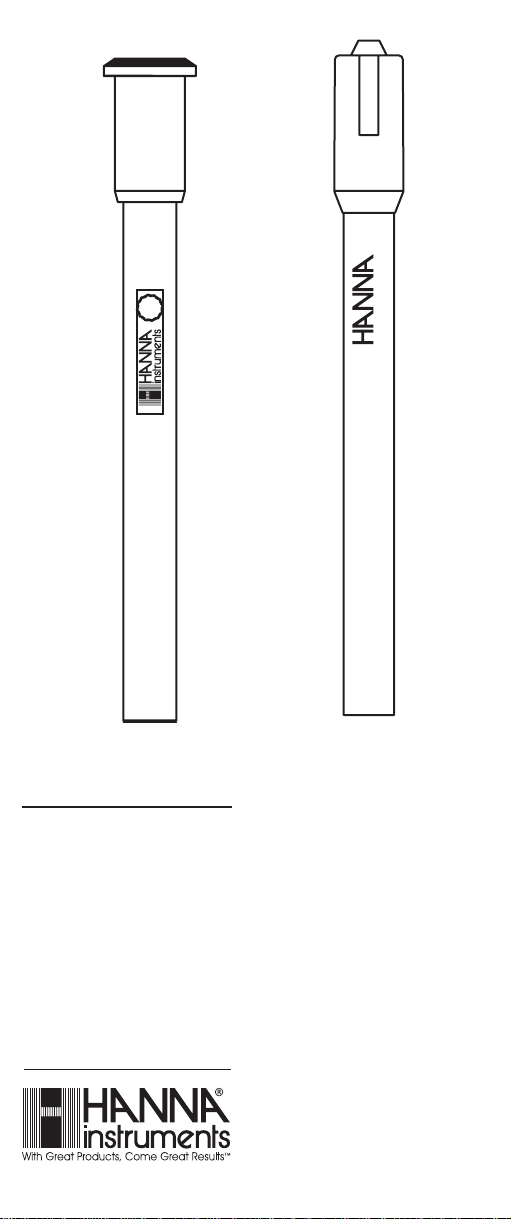
HI 4002 Bromide Half-cellHI 4002 Bromide Half-cell
HI 4002 Bromide Half-cell
HI 4002 Bromide Half-cellHI 4002 Bromide Half-cell
HI 4102 Bromide Combination ElectrodeHI 4102 Bromide Combination Electrode
HI 4102 Bromide Combination Electrode
HI 4102 Bromide Combination ElectrodeHI 4102 Bromide Combination Electrode
I. I.
Introduction:Introduction:
I.
Introduction:
I. I.
Introduction:Introduction:
The Hanna HI 4002and HI 4102 are ion selective electrodes designed for the measurement of Bromide ions in
aqueous solutions. The HI 4002 is a solid state half-cell
sensor that requires a separate reference. The HI 4102 is a
combination ion selective electrode.
IIII
SpecificationsSpecifications
II.
Specifications
IIII
SpecificationsSpecifications
Type: Solid State electrode with
a Silver Bromide pellet.
- -
-
Ion(s) measured: Bromide (Br
- -
)
Measurement range: 1.0 M to 1 X 10
-6
M
79,910 to 0.08 ppm
Interfering ions: Cyanide, and Mercury
must be absent. Ratio of
--
-
interfering ion to Br
--
must
be less than the ratio
indicated below:
0.01 for I
0.01 for CN
50 for Cl
--
-
--
iodide
--
-
--
cyanide
--
-
--
Chloride
Operating Temperature: 0-80°C
Operating pH: 2-12.5 pH
Dimensions: 12 mm (OD) X 120 mm
nominal insertion
(0.47” X 4.72”)
Connection: BNC
2
Page 3

III. III.
Theory of OperationTheory of Operation
III.
Theory of Operation
III. III.
Theory of OperationTheory of Operation
::
:
::
The HI 4002 or HI 4102 Bromide electrodes are potentiometric devices used for the rapid determination of free Bromide ions in food products, beverages, plants, soils and as
an indicator in titrations. The electrode functions as a sensor or ionic conductor. The HI 4002 requires a separate
reference electrode to complete its electrolytic circuit. The
HI 4102 incorporates a reference electrode. The silver Bromide pellet is practically insoluble in the test solutions
being measured and produces a potential change due to
changes in the sample’s ion activity. When the ionic strength
of the sample is fixed by the addition of ISA, the voltage is
proportional to the concentration of bromide ions in solution and the electrode follows the Nernst equation.
E= E
+ 2.3 RT/nF log A
a
ion
E= observed potential
Ea= Reference and fixed internal voltages
R= gas constant (8.314 J/K Mol)
n= Charge on ion (1-)
A i=ion activity in sample
T= absolute temperature in K
F= Faraday constant (9.648 x 10⁴ C/equivalent)
3
Page 4
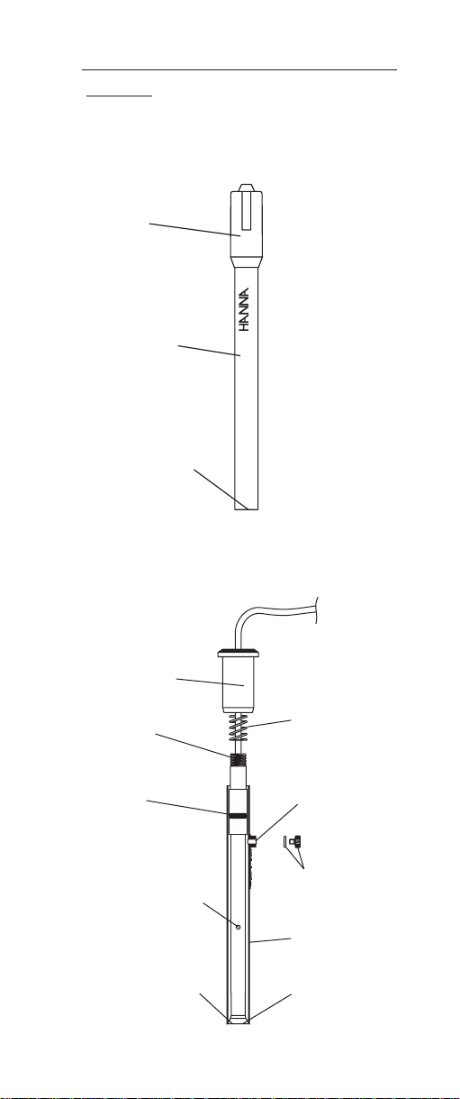
IV. IV.
Design elements of the HI 4002 and HI 4102Design elements of the HI 4002 and HI 4102
IV.
Design elements of the HI 4002 and HI 4102
IV. IV.
Design elements of the HI 4002 and HI 4102Design elements of the HI 4002 and HI 4102
electrodeselectrodes
electrodes
electrodeselectrodes
Cap
HI 4002
IDE
Sensor
M
BRO
Handle
Sensing
Membrane
Upper Cap
Upper
Threads
O-Ring
Ceramic Junction
on Inner Stem
Liquid junction
Spring
Fill Hole
O-Ring and
Plug
Outer Sleeve
Sensing
Membrane
4
Page 5

V. V.
Equipment required:Equipment required:
V.
Equipment required:
V. V.
Equipment required:Equipment required:
• Hanna HI 5315 Double Junction Reference Electrode
with HI 7072 Fill Solution for HI 4002.
• Hanna HI 4222 pH/ISE/mV meter or other suitable
ion or pH/mV meter. (Note: log/linear graph paper is
useful if an ISE (ion) meter is not available).
• Hanna HI 180 Magnetic Stirrer or equivalent with TFE
coated stirring bars (HI 731320). Note: isolate beakers from stirrer motor heat by placing insulating
material such as foam or cork between them.
• Hanna HI 76404 Electrode Holder or equivalent.
• Plastic beakers (HI 740036P) or other suitable mea-
surement vessel.
VI. VI.
Solutions RequiredSolutions Required
VI.
Solutions Required
VI. VI.
Solutions RequiredSolutions Required
for Bromide Measurementsfor Bromide Measurements
for Bromide Measurements
for Bromide Measurementsfor Bromide Measurements
0.1 M Bromide Standard, 500 mL HI 4002-01
ISA, 500 mL HI 4000-00
For Molar solutions:
Using volumetric pipettes and glassware make serial dilutions to approximately bracket the concentration of the
samples. Standards with concentrations < 10
-3
M should
be prepared daily.
Two mL of Hanna ISA for Halide electrodes (HI 4000-00)
should be added to 100 mL of sample or standard.
For ppm solutions:
Prepare 799 ppm bromide standard by diluting HI400201: Pipette 100 mL standard to a 1 liter volumetric flask.
Add deionized water to volume. Using additional volumetric pipettes and glassware make serial dilutions of this 799
ppm standard to approximately bracket the concentration
of the samples. Standards with concentrations < 80 ppm
should be prepared daily.
Two mL of Hanna ISA for Halide electrodes (HI 4000-00)
should be added to 100 mL of sample or standard.
5
Page 6

VIIVII
General GuidelinesGeneral Guidelines
VII.
General Guidelines
VIIVII
General GuidelinesGeneral Guidelines
• Calibration standards and sample solutions should
have the same ionic strength. ISA should be added to
both samples and standards in the same ratio. 1 part
ISA to 50 parts standard is the normal dosing.
• Concentrated samples (>1 M) should be diluted
before measurement. Multiply the final result by the
corresponding dilution factor.
• For high ionic strength samples, prepare standards
with similar ionic strength by increasing the ISA
addiiton.
• Calibration standards and sample solutions should
be at same temperature.
• The magnetic stirrer may generate heat. Thermally
insulate beaker containing standard or sample from
magnetic stirrer by placing cork or other insulative
sheet between beaker and stirrer plate.
• Calibration standards and sample solutions should
be stirred at the same rate using identical sized TFE
coated stir bars.
• Rinse electrode pair with distilled or deionized water
between samples and gently dab dry with soft disposable absorbent toweling. Do not rub electrodes.
• Presoaking bromide sensor in a dilute standard will
optimize response. Use concentrations approximately
10-3M or less.
• A scratched, pitted, or tarnished pellet surface can
cause drift, a loss of low level response, or poor repeatability. Optimum response can be restored by removing the damaged surface with the microabrasive strip
HI 4000-70.
• Avoid large changes in temperature (thermal shock)
as it may damage the sensor.
• Gas bubbles may form from solution out-gassing due
to temperature change. Gently tap body of sensor to
dislodge them from membrane surface.
6
Page 7

HI 4002
• Remove protective cover from sensor tip.
• Prepare HI 5315 reference electrode by filling electro-
lyte reservoir with HI 7072 fill solution.
• Place sensor and reference electrodes into electrode
holder and connect cable connectors to meter.
HI 4102
• Remove the protective plastic wrap that covers the
ceramic junction before assembling sensor for the first
time.
• HI 7072 reference fill solution should be added daily
to electrolyte reservior before electrode use.
• During measurement always operate electrode with
the fill hole open.
• During normal use, fill solution will slowly drain out
of the tapered cone junction at the lower portion of the
electrode. Excessive loss (>4 cm drop within 24 hours)
is not normal. If this occurs verify cap is tightened and
the interface between the internal cone and outer
body is free of debris.
• Add fill solution daily to maintain a good head pressure. For optimum response, this level should be maintained and not be allowed to drop more than 2-3 cm
(1-inch) below fill hole. It must cover the ceramic
found on the inner stem.
• If an erratic measurement occurs, check to see if foreign matter is seen trapped near the internal cone.
Drain and refill with fresh fill solution.
7
Page 8

VIII. VIII.
Electrode PreparationElectrode Preparation
VIII.
Electrode Preparation
VIII. VIII.
Electrode PreparationElectrode Preparation
HI 4002
1. Remove protective cover from sensor tip.
2. Prepare reference electrode by filling outer electrolyte
reservoir with HI 7072.
3. Place sensor and reference electrodes into electrode
holder and connect cable connectors to meter.
HI 4102
1. Unwrap plastic film seal found over ceramic junction
on inner stem and discard. This is only used for shipping and long term storage.
2. Rinse inner stem with deionized water making certain
to wet the o-ring found on the inner stem.
Remove
Water
Deionized
3. Reassemble electrode by gently pushing the inner
assembly into the outer body, sliding spring down
cable, and screwing cap into place.
4. Remove fill hole cover and o-ring on fill hole spout.
5. Using the dropper pipette provided, add a few drops
HI 7072 fill solution to the electrode, wetting the oring and rinsing out the fill solution chamber.
8
Parafilm
Page 9

6. Holding the body of the electrode gently press upper
cap with your thumb. This permits the fill solution to
drain out of the body. Release cap and verify electrode returns to its original position. (You may need to
gently assist for this to occur).
COMBINATION
BROMIDE
HI 4102
7. Tighten the electrode cap onto the body and fill electrode body until fill solution volume is just below fill
hole.
8. Position electrode in a Hanna HI 76404 electrode
holder (or equivalent) and connect plug to meter.
9
Page 10

IX. IX.
Quick Check of Electrode SlopeQuick Check of Electrode Slope
IX.
Quick Check of Electrode Slope
IX. IX.
Quick Check of Electrode SlopeQuick Check of Electrode Slope
• Connect sensors to pH/mV/ISE meter
• Place meter in mV mode.
• Place 100 mL of DIW into a beaker with stir bar.
• Place electrodes into prepared sample.
• Add 1 mL of a standard (0.1 M or 1000 ppm stan-
dard) to beaker. Record the mV value when stable.
• Add an additional 10 mL of standard to the solution.
Record the mV when reading has stabilized. This
value should be less than the previous noted (more
negative).
• Determine the difference between the two mV values.
An acceptable value for this slope is -56 ± 4 mV.
X. X.
Corrective actionCorrective action
X.
Corrective action
X. X.
Corrective actionCorrective action
• Verify protective cap has been removed (HI 4002).
• Verify plastic film has been removed from inner stem
(HI 4102).
• Verify electrodes are connected properly to meter and
meter is powered.
• Verify dilute standards are freshly made and stored.
Remake solutions if appropriate.
• If the sensor slope just misses the suggested slope
window, soaking the sensor in a dilute standard may
solve the problem. (<10
-3
M bromide or <80 ppm
standard).
• A scratched sensing surface can be polished with HI
4000-70 polishing strip. Cut off approximately 1
inch of the micro-abrasive strip. Wet the frosted side
with deionized water and place against damaged
membrane of the electrode. Place your thumb against
the shiny backing and slowly rotate back and forth
while applying gentle pressure. Continue polishing
until you are satisfied with the surface. If dark deposits appear on polishing strip move the paper slightly
and continue polishing.
10
Page 11

• If the membrane is damaged, the response becomes
extremely sluggish, or the slope of the electrode has
decreased significantly, and procedures above have
not helped, the sensor should be replaced.
XI. XI.
Direct Calibration and MeasurementDirect Calibration and Measurement
XI.
Direct Calibration and Measurement
XI. XI.
Direct Calibration and MeasurementDirect Calibration and Measurement
This method is a simple procedure for measuring many
samples. A direct reading ISE meter (HI 4222 or equivalent) determines concentration of the unknown by a direct
reading after calibrating the meter with the standards. The
meter is calibrated with two or more freshly made standards that are in the linear measurement range of the
unknowns. More calibration standards are required in nonlinear regions. Unknowns are read directly. At very low
levels of bromide, special precautions must be employed
for reproducible measurements. Water used for standards
must be bromide free and sensors and glassware must be
rinsed repeatedly with this water to prevent carry over. In
the region where the electrode response appears curved,
more calibration points are needed, and calibration will
need to be repeated more frequently.
A pH/mV meter in mV mode with semi log graph paper
may also be used. Two or more freshly prepared standards
that are in the measurement range of the unknowns are
measured in mV mode on the meter.
These values are plotted on the semi-log paper and the
points are connected to form a straight-line curve. When
samples are measured, their mV values are converted to
concentration by following the mV to the concentration axis
on the semi-log plot.
11
Page 12

Procedure
1) Follow sections VIII and IX to prepare sensors for
measurement.
2) Follow section VI to prepare standards/ solution. Standards should bracket and fall within the range of
interest.
Two mL HI 4000-00 ISA, is added to 100 mL of both
samples and standards Add stir bar and mix before
taking measurements.
3) Follow section VII; General Guidelines to optimize test
set-up.
4) During calibration it is best to start with lower concentration samples first. Wait for a stable measurement
before recording values. Slightly longer equilibrations are required at lower concentrations .
5) To prevent carry over and contamination of samples,
rinse sensors with DIW and dap dry between samples.
Typical Linearity for HI 4002 and HI 4102 Bromi de
-150
-100
-50
0
mV
50
100
150
200
01234567
sensors
-Log of Molar Conc entration
12
Page 13

XII. XII.
Other Measurement TOther Measurement T
XII.
Other Measurement T
XII. XII.
Other Measurement TOther Measurement T
echniquesechniques
echniques
echniquesechniques
Known Addition (for Br-)
An unknown concentration can be determined by adding a
known amount (volume and concentration) of measured
ion to a known volume of the sample. This technique is
called Known Addition. The method can use an ideal
sensor slope, but actual determined slopes at the temperature of measurement should be used if known. The volume
and concentration of the added standard must cause a mV
change of at least 30 mV. This method is preprogrammed
in the Hanna HI 4222 pH/ISE/mV meter, which simplifies
the method greatly.
Example: Bromide ion determination with known addition.
1. A 50 mL sample of unknown (Vsample) is placed in
a clean plastic beaker with a bromide sensor. Add 2
mL of HI 4000-00 ISA (V
), mix well and record the
ISA
stable mV value (mV 1).
2. 5 mL (Vstd) of 10-1M (Cstd) standard is added to the
beaker and the mV value decreases. The unknown
bromide concentration in the original sample
(Csample) can then be determined by the following
equation.
C
=
sample
(V
(V
sample+Vstandard+VISA
(V
sample+VISA
C
standardVstandard
∆E/S
)10
T
)= V
- (VS’)
)= V
S’
V
S’
V
sample
T
3. The procedure can be repeated with a second stan-
dard addition to verify slope and operation of the
method.
13
Page 14

TitrationTitration
Titration
TitrationTitration
A bromide electrode may be used as an indicator to follow
the progress of a bromide tiration with silver nitrate. The
electrode can be used in colored samples where other
indicators suffer from interferences. During the titration the
sensor follows the decrease in bromide concentration while
small additions of silver nitate titrant are added. The silver
reacts with the bromide ions forming a precipitate of silver
bromide. At the stoichiometric end point, a large change
in mV occurs. Measurements may be automated by use of
the Hanna Titrator HI 901 or titrated manually.
XIII.XIII.
pHpH
XIII.
pH
XIII.XIII.
pHpH
The HI 4102 and HI 4002 electrodes may be used in
solutions with pH values between 2 and 12.5. Samples
that fall beyond this range should be adjusted.
XIV. SXIV. S
torage and Care of the HI 4002 andtorage and Care of the HI 4002 and
XIV. S
torage and Care of the HI 4002 and
XIV. SXIV. S
torage and Care of the HI 4002 andtorage and Care of the HI 4002 and
HI 4102 sensorsHI 4102 sensors
HI 4102 sensors
HI 4102 sensorsHI 4102 sensors
The HI 4002 sensor can be stored in very dilute standards
(<10-3M) for short periods of time and should be stored
dry with the protective cap on when not in use.
The model HI 4102 combination electrode can be left in
dilute standards (<10-3 M) for short time periods.
For long term storage, the electrode should be drained and
washed of salts with distilled ot deionized water. Unscrew
the upper cap and move outer sleeve up cable. Wrap the
ceramic junction on the inner stem with Parafilm® or other
sealing wrap. Place the protective cap provided over the
sensor membrane. Store dry disassembled electrode in
storage box provided with electrode.
14
Page 15

XVXV
. .
Conversion TConversion T
XV
.
Conversion T
XVXV
. .
Conversion TConversion T
For BrFor Br
For Br
For BrFor Br
ablesables
ables
ablesables
--
-
--
Multiply byMultiply by
Multiply by
Multiply byMultiply by
Moles/L (M) to ppm (mg/L) 7.99 x 10
ppm (mg/L) to M (moles/L) 1.252 x 10
4
-5
15
Page 16

MAN4102 11/07
WARRANTY WARRANTY
WARRANTY
WARRANTY WARRANTY
Hanna Instruments Ion Selective Electrodes are warranted
to be free of defects in material and workmanship for 6
months from date of purchase when used for their intended
purpose and maintained according to instructions. If they
fail to work when first used contact your dealer immediately.
Damage due to accidents, misuse, misapplication, tampering
or lack of prescribed maintenance is not covered.
Hanna Instruments reserves the right to modify the design,
construction or appearance of its products without advance
notice.
16
 Loading...