

HanleyLED Concorde Cabinet System Installation Manual
GENERAL PURPOSE
RETROFIT SIGN
CONVERSION
FOR USE ONLY IN
ACCORDANCE WITH KIT
INSTRUCTIONS
KIT IS COMPLETE ONLY WHEN ALL PARTS
REQUIRED BY THE INSTRUCTIONS ARE PRESENT
12.18.18
BEFORE YOU BEGIN
Determine your light bar mounting method. Are you using pre-existing sockets to mount?
If so, Retrot Connectors are included. If not, be sure to purchase our Speed Spring Brackets
for fast and secure mounting.
READ THESE INSTRUCTIONS COMPLETELY AND CAREFULLY
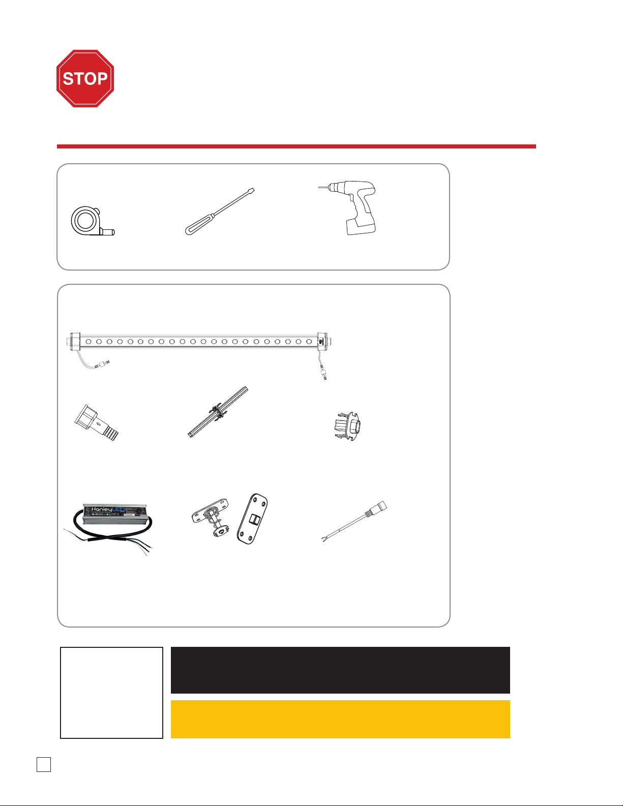
Tools required:
Screwdriver Electric DrillTape Measure
Components:
Concorde Cabinet Bars
24v Power Supply Speed Spring Bracket Set
(Spring and stationary)
Optional
Retrot (RF) ConnectorWatertight End Cap Concorde Joint
Concorde Cable Connectors
Optional
NOTE:
All materials removed
must be disposed of
in accordance with
applicable local, state,
and federal laws.
2
WARNING check polarity: All connections must be WHITE-TO-RED (+) and BLACK-TO-BLACK (-).
Reverse polarity connections may damage the LEDs and will void product warranty.
Caution: Turn o power to sign before inspecting or removing existing light source.
Power must remain o while installing the Concorde Cabinet System.

RETROFIT INSTALLATION GUIDE
Concorde Cabinet System
This guide is designed to aid in the installation of HanleyLED’s Concorde Cabinet System. Skilled trades people that are familiar with
general construction, electrical, and sign installation techniques should do the installation. Licensed electricians should provide all
installation and hook-up of both the primary and secondary input/outputs of the HanleyLED power supply. All installation and hookup should be done in accordance with all National and Local codes and permits. In no way is this document intended to construe
warranty or tness of use of the products described, nor is it intended to provide safety instruction for those installing the product.
THE FIELD INSTALLATION OF THIS RETROFIT SYSTEM INTO A SIGN IS SUBJECT TO THE
ACCECPANCE OF LOCAL INSPECTION AUTHORITY.
CAUTION: TURN OFF POWER TO THE SIGN BEFORE INSPECTING OR REMOVING EXISTING LIGHT
SOURCE. THE POWER MUST REMAIN OFF WHILE INSTALLING THE LED RETROFIT KIT.
Tools Required:
• Wire cutter & strippers
• Measuring tape
• Marking pens
• Drill
• Standard hardware and supplies in addition to the HanleyLED modules
installation guides (UL listing may be required on certain items)
Prepping the Channel Letter or Cabinet
Step 1
Remove existing neon or uorescent bulbs by having a licensed electrician disconnect and remove the neon transformers or
uorescent ballasts. Remove existing neon and standos or uorescent lamps. Leave uorescent sockets in cabinets with leads
disconnected. This should leave an empty channel letter or cabinet.
NOTE: ALL MATERIALS REMOVED MUST BE DISPOSED OF IN ACCORDANCE WITH
APPLICABLE LOCAL, STATE AND FEDERAL LAWS.
Step 2
Using a non- oil based cleaner, clean the back surfaces of the channel letter or cabinet where the LED modules will be mounted.
This is an important step for good adhesion of HanleyLED modules mounting tape.
Step 3
Installer should examine all parts that are not intended to be replaced by the retrot kit for damage and replace any damaged
parts prior to installation of the retrot kit. Do not make or alter any open holes in an enclosure of wiring or electrical
components during kit installation. Any existing holes in the letters or cabinet that will not be used in the installation of HanleyLED
modules should be patched to avoid water damage. Openings smaller than ½” diameter may be sealed with the appropriate
amount of rated caulk or sealant. Openings larger than ½” should be patched using an aluminum or zinc coated steel patch with
rivets and sealant.
Step 4
Proceed with the appropriate HanleyLED module installation guide for your specic product.
Installation Guide | www.hanleyledsolutions.com | 800.542.9941
3
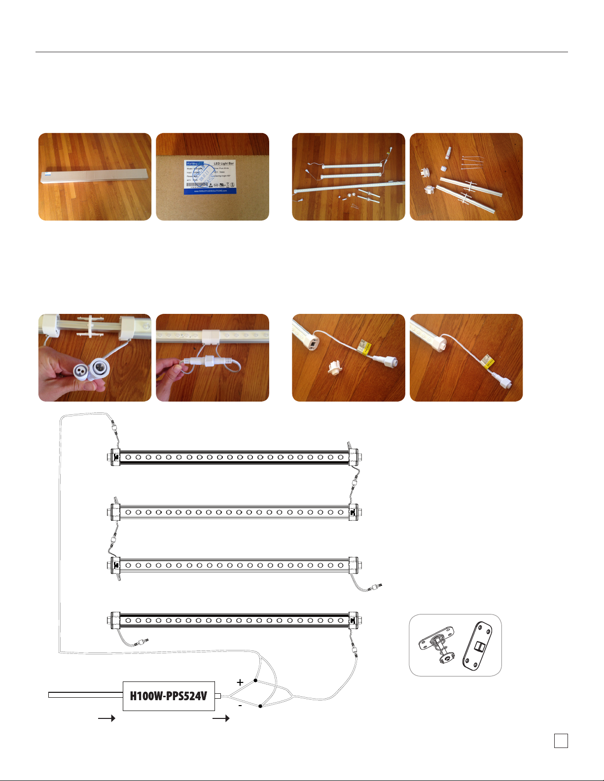
Concorde Cabinet System Quick Assembly
Step 1
Order the size light bar just as you would order your replacement orescent
lamps. Pick the size you want. Ever ything you’ll need to ass emble the bar will be
in the box. This guide shows how to ass emble a 96” Concorde LED Bar System.
Step 3
Connect all your Concorde pie ces by using the Concorde Connec tor Joints.
Tighten the watertight wire ports.
** Pay attention to the male and female ends when assembling.
Step 2
Make sure you have all your pieces for ass embly. Take all the Concorde
components out of the box.
Step 4
Place your Concorde Retrot (RF) Connector s on each side of the bar. The RF Connec tors mount
straight into the HO socket s of your existing cabinet making this an easy retrot install. Screw
in Watertight End Cap to the unused wire por t.
Input
Output
Installation Guide | www.hanleyledsolutions.com | 800.542.9941
For new construction, the Conorde Speed
Spring brackets are available for purchas e
4
Retrot Installation For Use With Existing Fluorescent Box Signs
1. Remove Existing Fluorescent Tubes 2. Connect all light bar pieces, if necessary.
• Make sure power is o. Have a licensed electrician disconnect and remove all ballasts.
• Remove existing uorescent tubes, leaving uorescent lamp holders in place.
• Installers should disconnect lamp holder leads and make new connections from the LED driver directly to the LED
lamps. Lamp holders are to be used only for the purpose of holding the LED lamps in place.
• (Existing Signs Only) If removal of the existing lighting equipment eliminates the disconnect switch, as required by
applicable local, state, or country electrical codes; a new disconnect switch must be installed.
• (Existing Signs Only) Make sure the removal of lighting equipment does not compromise the integrity of the sign body
(i.e. water intrusion). Fill in all holes 0.5 in. (13 mm) or smaller with the appropriate amount of rated caulk or sealant.
For holes greater than 0.5 in. (13 mm), use an aluminum or zinc coated steel patch with rivets and sealant.
Install Retrot Connectors on each side of light bar.
3. Insert Light bars into lamp-sockets
End Cap provided in box, or use another extension cable
to tie the port back to the power supply.
This sign
has been
modied
to operate
LED lamps.
Do not
attempt
to install
or operate
uorescent
lamps in
this sign.
8. This sign has been modied to operate LED lamps. Do not attempt to
install or operate uorescent lamps in this sign. The marking for item
shall have a minimum letter height of 2.4 mm (3/32 in) and shall be in
Universal Bold, Arial Bold, Helvetica Bold, or Zurich BT Bold or equivalent
font. Markings in this image shall be provided verbatim.
4. Connections: Wire the Concorde bars with male and female connectors to make longer
cascade. (see Cascading Information Guidelines on page 7 to see how many bars can
be run in a series)
6. Mount power supply5. Unused wire ports should be capped with Watertight
• Identify input and output secondary wires. Connect the power unit to the supply
in accordance with the applicable local, state, and country electrical codes, and the
instructions found in the power supply installation guide. All power supplies must be
installed in a raceway or suitable electrical enclosure.
• If required, the disconnect switch shall be installed by qualied personnel, in
accordance with applicable local, state, and country electrical codes.
• Spacing between LED power supplies shall be at least 25.4 mm (1 in) from end to end
and 101.6 mm (4 in) from side to side, in accordance with UL 48 Par. 4.2.3.2.3.1
7. Connect to power supply: Connect the white output
wire to the red Concorde cable wire and the black
output wire to the black cable wire. Connect female
cable end to male end coming o of Concorde bar and
tighten collar.
5
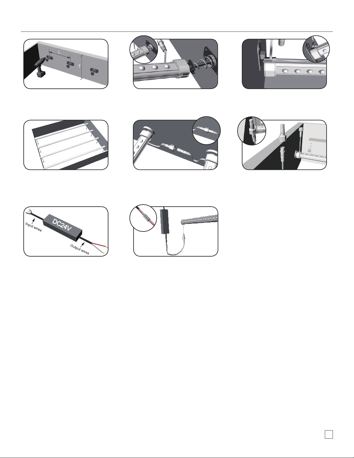
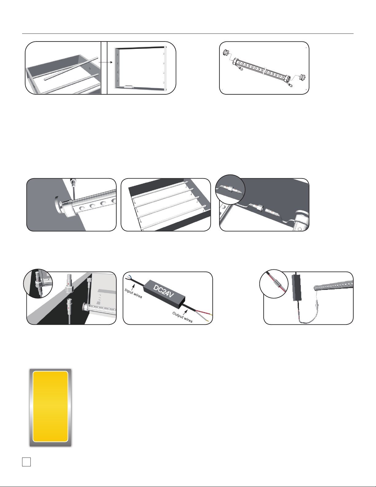
New Construction Installation
1. Mount Speed Spring Brackets and Stationary Brackets to each
side of sign box. (Mount bracket base parrallel to the direction
of your raceway)
4. Verify all LEDs of light bars point to sign face. 5. Connections: Wire the Concorde bars with male and female
2. lnsert Light bars onto Speed Spring Brackets rst. 3. Push the Concorde Bars down onto the Speed Spring Bracket,
connectors to make longer cascade. (see Cascading
Information Guidelines on page 7 to see how many bars can
be run in a series)
then insert other end onto stationary bracket.
6. Unused wire ports should be capped with Watertight End
Cap provided in box, or use another extension cable to tie
the port back to the power supply.
7. Mount power supply
• Identify input and output secondary wires. Connect the
power unit to the supply in accordance with the applicable
local, state, and country electrical codes, and the
instructions found in the power supply installation guide.
All power supplies must be installed in a raceway or suitable
electrical enclosure.
• If required, the disconnect switch shall be installed by
qualied personnel, in accordance with applicable local,
state, and country electrical codes.
• Spacing between LED power supplies shall be at least
25.4 mm (1 in) from end to end and 101.6 mm (4 in) from
side to side, in accordance with UL 48 Par. 4.2.3.2.3.1
8. Connect to power supply: Connect the white output wire to
the red Concorde cable wire and the black output wire to the
black cable wire. Connect female cable end to male end
coming o of Concorde lamp and tighten collar.
9. Make sure all wire connections are ready and correct.
Installation Guide | www.hanleyledsolutions.com | 800.542.9941
6
 Loading...