


3158050 Rev. E 1/08
XX-XXX-X
Internal Use Only
3158050e / 080102
INSTRUCTION MANUAL
HBP SERIES
MODELS
HBP500
HBP600
HBP750
HBP900
HBP1050
HBP1300
HBP1500
HBP1800
HBP2200
HBP2600
HBP3200
HBP3600
HBP4300
RATED
FLOW
500 SCFM
600 SCFM
750 SCFM
900 SCFM
1050 SCFM
1300 SCFM
1500 SCFM
1800 SCFM
2200 SCFM
2600 SCFM
3200 SCFM
3600 SCFM
4300 SCFM
MODEL
REFERENCE
500
600
750
900
1050
1300
1500
1800
2200
2600
3200
3600
4300
Contents
1.0 General Safety Information ........................... 2
2.0 Receiving, Storing, and Moving ..................... 2
3.0 Description .................................................... 3
4.0 Installation ..................................................... 3
5.0 Instrumentation .............................................. 8
6.0 Operation ....................................................... 12
7.0 Maintenance .................................................. 29
8.0 Troubleshooting ............................................. 31
BLOWER PURGE
DESICCANT
COMPRESSED
AIR DRYERS
Drawings
P&ID Schematic Models 500 through 600 ............ 34
P&ID Schematic Models 750 through 4300 .......... 36
Electrical Schematic – 460VAC, 3 phase .............. 38
Electrical Schematic – 575VAC, 3 phase .............. 39
Electrical Schematic – 380VAC, 3 phase .............. 40
Electrical Schematic – 415VAC, 3 phase .............. 41
Electrical Data – Fusing & Wire Sizing .................. 42
WARRANTY .......................................................... 44
SERVICE DEPARTMENT : (724) 746-1100

1.0 General Safety Information
DANGER—Immediate hazard which will result in severe
injury or death.
This equipment is designed and built with safety as a
prime consideration; industry-accepted safety factors
have been used in the design. Each dryer is checked at
the factory for safety and operation. All pressure vessels which fall under the scope of ASME Section VIII,
are hydrostatically tested in accordance with the latest
addenda. A factory-installed safety relief valve is standard
on each dryer.
WARNING — The following safety rules must be
observed to ensure safe dryer operation. Failure to
follow these rules may void the warranty or result in
dryer damage or personal injury.
1. Never install or try to repair any dryer that has been
damaged in shipment. See the Receiving and Inspection instructions in this manual for appropriate
action.
2. This equipment is a pressure-containing device.
Never operate the dryer at pressures or temperatures
above the maximum conditions shown on the data
plate.
Never dismantle or work on any component of the
dryer or compressed air system under pressure.
Vent internal air pressure to the atmosphere before
servicing.
3. This equipment requires electricity to operate. Install
equipment in compliance with national and local electrical codes. Standard equipment is supplied with
NEMA 4, 4X electrical enclosures and is not intended
for installation in hazardous environments.
Never perform electrical service on the dryer unless
the main power supply has been disconnected. Parts
of the control circuit may remain energized when the
power switch is turned off.
WARNING—Hazard or unsafe practice which could
result in severe injury or death.
CAUTION—Hazard or unsafe practice which could result
in minor injury or in product or property damage.
The dryer data plate, attached to the electrical control
box, contains critical safety and identification information. If the data plate is missing or defaced, immediately
contact your local distributor for a replacement.
2.0 Receiving, Storing, and Moving
2.1 Receiving and Inspection
This shipment has been thoroughly checked, packed
and inspected before leaving our plant. It was received
in good condition by the carrier and was so acknowledged.
Immediately upon receipt, thoroughly inspect for visible
loss or damage that may have occurred during shipping.
If this shipment shows evidence of loss or damage at
time of delivery to you, insist that a notation of this loss or
damage be made on the delivery receipt by the carrier’s
agent. Otherwise no claim can be enforced against the
carrier.
Also check for concealed loss or damage. When a shipment has been delivered to you in apparent good order,
but concealed damage is found upon unpacking, notify
the carrier immediately and insist on his agent inspecting
the shipment. The carrier will not consider any claim for
loss or damage unless an inspection has been made. If
you give the carrier a clear receipt for goods that have
been damaged or lost in transit, you do so at your own
risk and expense. Concealed damage claims are not our
responsibility as our terms are F.O.B. point of shipment.
Shipping damage is not covered by the dryer warranty.
4. Air treated by this equipment may not be suitable
for breathing without further purification. Refer to
OSHA standard 1910.134 for the requirements for
breathing quality air.
5. Certain parts of the dryer are not insulated and may
become hot during normal operation of the dryer. Do
not touch any of these areas without first determining
the surface temperature.
6. Use only genuine replacement parts from the manufacturer. The manufacturer bears no responsibility for
hazards caused by the use of unauthorized parts.
Safety instructions in this manual are boldfaced for
emphasis. The signal words DANGER, WARNING and
CAUTION are used to indicate hazard seriousness levels
as follows:
2
2.2 Storing
Store the dryer indoors to prevent damage to any electrical or mechanical components. All packaging material
should be left in place until the dryer is in position.
2.3 Handling
The dryer is designed to be moved by means of the shipping skid or the base channels. The dryer may also have
lifting lugs for use with an overhead crane. Be sure to
attach all of the lift points and use appropriate spreader
bars to prevent damage to the dryer.
CAUTION — Never lift the dryer by attaching hooks
or slings to the piping, or to any part other than the
lifting lugs. Severe structural damage could occur.

3.0 Description
3.1 Function
Blower purge type regenerative dryers are an economical and reliable way to dry compressed air to dew points
below the freezing point of water. Desiccant dryers lower
the dew point of compressed air by adsorbing the water
vapor present in the compressed air onto the surface of
the desiccant. Adsorption continues until equilibrium is
reached between the partial pressure of the water vapor
in the air and that on the surface of the desiccant.
systems supplied by a lubricated air compressor, use a
High Efficiency Oil Removal Filter. A coarser filter will
be required upstream of the Oil Removal Filter if heavy
liquid or solid loads are present.
To ensure downstream air purity (prevent desiccant dust
from traveling downstream) adequate filtration downstream of the dryer is required. A High Temperature
Afterfilter, typically rated at 450°F (232°C) operating
temperature and capable of removing all desiccant
fines 1 micron and larger should be installed at the dryer
outlet.
These dryers continuously dry compressed air by using
two identical towers, each containing a desiccant bed.
While one tower is on-stream drying, the other tower is
off-stream being regenerated (reactivated, i.e. dried out).
The towers are alternated on- and off-stream so that dry
desiccant is always in contact with the wet compressed
air. In this way a continuous supply of dry air downstream
of the dryer is possible. The switching from one tower
to the other is controlled by a solid-state controller on
either a fixed time basis (standard) or a demand basis
(optional).
When a tower is placed off-line, it is slowly depressurized and the desiccant is regenerated. First, a blower
draws in ambient air which is heated. The heated air
flows through the desiccant bed, desorbs the moisture
from the desiccant, and carries the desorbed water out
of the dryer. The blower and heater are turned off when
the desiccant bed is fully heated. When configured for
cooling, a portion of the dry compressed air is diverted
from the main air flow and throttled to near atmospheric
pressure. This extremely dry, low pressure air passes
through the hot off-line tower, partially cooling the desiccant bed and reducing the dew point spike after tower
change over. At the end of the cooling stage, the tower
is repressurized to full line pressure. This prevents desiccant bed movement and downstream pressure loss when
the tower goes back on-line.
4.0 Installation
4.1 System Arrangement
Install the dryer downstream of an aftercooler, separator,
receiver, and high-efficiency oil-removing filter(s) so that
the dryer inlet air is between 40°F (4.4°C) and 120°F
(49°C) and contains no liquid water or oil. Liquid water
and/or inlet air temperatures above 100°F (37.8°C) can
reduce drying capacity. Contact your local distributor
for information on proper dryer sizing at elevated inlet
air temperatures.
Adequate filtration is required upstream of the dryer in
order to protect the desiccant bed from liquid and solid
contamination. Use an Air Line Filter in systems supplied by a non-lubricated (oil-free) air compressor. In
DANGER — This dryer must be fitted with a high
efficiency coalescing filter and liquid drainer that is
maintained properly. Failure to do so could result
in an in-line fire.
WARNING — The afterfilter, if installed, must be rated
for 450°F (232°C).
4.2 Ambient Air Temperature
Locate the dryer under cover in an area where the ambient air temperature will remain between 35°F (2°C) and
120°F (49°C).
NOTE: If dryer is installed in ambients below 35°F
(2°C), low ambient protection requiring heat tracing
and insulation of the prefilter bowls, auto drains and/
or sumps, and lower piping with inlet switching and
purge/repressurization valves is necessary to prevent
condensate from freezing. If installing heat tracing, observe electrical class code requirements for type of duty
specified. Purge mufflers and their relief mechanisms
must be kept clear from snow and ice buildup that could
prevent proper discharge of compressed air.
4.3 Location and Clearance
Install the dryer on a level pad. Ensure the dryer is
level by grouting or shimming as necessary. Holes are
provided in the dryer base members for floor anchors.
Securely anchor the dryer frame to the floor. Allow 24
inches clearance on all sides of the dryer for servicing. Provide adequate clearance for prefilter element,
afterfilter element and heater element replacement.
Provide protection for the dryer if it is installed where
heavy vehicles or similar portable equipment is likely to
cause damage.
4.4 Piping and Connections
All external piping must be supplied by the user unless
otherwise specified. Refer to Figure 2 for connection
sizes. Inlet and outlet isolation valves and a vent valve
are recommended so the dryer can be isolated and
depressurized for servicing. The connections and pipe
fittings must be rated for or exceed the maximum operating pressure given on the dryer nameplate and must
be in accordance with industry-wide codes. Be sure all
3

Compressor Aftercooler Separator Receiver Prefilters Afterfilters ReceiverDesiccant Dryer
Figure 1
Typical System Configuration
piping is supported. Do not allow the weight of any piping to bear on the dryer or filters. Piping should be the
same size as or larger than the dryer connection. Piping
smaller than the dryer connections will cause high pressure drop and reduce drying capacity.
If the purge exhaust piping must be extended outside the
dryer area, choose a combination of diameters, lengths,
and turns that limits the additional pressure drop to 1/4
psid or less. BACK PRESSURE WILL CAUSE DRYER
MALFUNCTION. Consult the factory for piping details
if required.
WARNING — Do not operate dryer without installed
mufflers. Exhausting compressed air directly to
atmosphere will result in noise levels above OSHA
permissible levels and rapidly expanding gas could
potentially cause harm to persons or property.
Dryer bypass piping may be installed to allow uninterrupted airflow during servicing. If the downstream application cannot tolerate unprocessed air for short periods,
install a second dryer in the bypass line.
CAUTION — Do not hydrostatically test the piping
with the dryer in the system. The desiccant will be
damaged if saturated with water.
4.5 Electrical Connections
WARNING — These procedures require entering
gaining access to the dryer’s electrical enclosure(s).
All electrical work must be performed by a qualified
electrical technician.
Connect the proper power supply to the dryer according
to the electrical drawings in the back of this manual. Be
sure to follow all applicable electrical codes.
NOTE: A disconnect switch is not provided as standard
equipment and therefore, must be supplied by the customer.
Dry contacts (voltage free) are provided in the low tension electrical enclosure for a remote alarm. The contact
ratings are shown on the electrical drawing.
Connections to voltage-free common alarm contacts
with a minimum 5-amp rating can be made at terminals
TB4-1 through 3.
• Terminal TB4-3 is the common alarm connection.
• Terminal TB4-1 is the N.O.. (normally open) contact
connection.
• Terminal TB4-2 is the N.C. (normally closed) contact
connection.
• The alarm relay coil is energized when power is
supplied to the controller input terminals and there
is no alarms.
• The coil is de-energized when power is removed or
when an alarm condition exists.
NOTE: Before turning high voltage on to the dryer, an
ohmic test should be performed on the heater elements
to insure they are dry before proceeding with start-up.
This should be done after extended shut downs and long
delays between delivery and start-up. Connect one lead
of a megger to an unpainted surface of the control panel
or dryer frame. Connect the other lead to each phase
on the load side of the contactor. Adjust the megger to
the 1500 volt setting. Perform the ohmic test on each
zone of the heaters. A minimum value of 500k ohms
must be obtained.
CAUTION - Failure to ohmic test heaters after extended periods may cause heater failure.
4.5.1 RS-232 Connections
RS-232 connections can be made at the 3-pin connector
labeled J3 and located at the upper left-handed corner
of the control board. A cable for this connection can be
purchased through your distributor.
4.6 Initial Desiccant Charge
Blower purge type regenerative dryers use activated
alumina as the desiccant in the dryer towers.
Models 500 through 1050 are shipped with activated
alumina (1/8” bead) in the dryer towers. Desiccant is
shipped loose with all other standard models.
4

All desiccant shipped loose must be added to the
dryer chambers before the dryer is put into service
Refer to TABLE 1, DESICCANT REQUIREMENTS for
desiccant type and quantity per tower.
TO ADD DESICCANT
WARNING — The following procedure provides instructions for adding the initial desiccant to the towers. If replacing desiccant, refer to the “Procedure
for Desiccant Charge Replacement” in Section 7.0.
1. Verify pressure gauges of both towers indicate
0 psig. If not, depressurize the towers according to
the shutdown instructions in Section 6.
2. Remove the pipe plug or fill port flange cover (where
applicable) from the desiccant fill port at the top of
each tower. Refer to Figure 3 for the fill port location.
CAUTION – Pouring desiccant creates a fine dust;
safety goggles, gloves and a dust mask should be
worn by personnel installing desiccant. Refer to the
Material Safety Data Sheet that accompanies desiccant shipped loose for more complete information.
CAUTION – Do not tamp the desiccant in the towers.
Tamping damages desiccant and causes dusting.
3. Refer to Table 1 for desiccant quantity per tower.
When using Table 1 you will find the desiccant quan-
tities listed in layers. Each layer will vary in depth
due to the type, quantity and purpose of the desiccant. Layer 1 must be installed first at the bottom of
the vessel followed by layer number 2 etc., until the
complete charge of desiccant has been installed.
TABLE 1
DESICCANT REQUIREMENTS
(Quantity per Tower)
Layer
Model
500
600
750
900
1050
1300
1500
1800
2200
2600
3200
3600
4300
* AA = Activated Alumina
** TS = Tabular Support
1 2 3
354#
1/8” bead AA
453#
1/8” bead AA*
590#
1/8” bead AA
590#
1/8” bead AA*
710#
1/8” bead AA
48#
1/4” bead AA*
92#
1/4” bead AA*
92#
1/4” bead AA*
161#
1/4” bead AA
161#
1/4” bead AA*
258#
1/4” bead AA*
258#
1/4” bead AA*
719#
1/2” bead TS**
1/8” bead AA*
1/8” bead AA*
1/8” bead AA*
1/8” bead AA*
1/8” bead AA*
1/8” bead AA*
1/8” bead AA*
1/4” bead AA*
— —
— —
— —
— —
— —
876#
1167#
1167#
1706#
1706#
2119#
2353#
146#
1/8” bead AA*
—
—
—
—
—
—
—
2679#
4. Utilizing an appropriate sized funnel, fill each desiccant tower as follows:
a. Install the required quantity of tabular support or
activated alumina in layer 1 of each tower.
b. Level layer 1 and each subsequent layer of desic-
cant as added to each chamber.
c. Finish filling each tower with desiccant until all
desiccant has been installed. LIGHT tapping
on the tower sides with a soft-face mallet should
yield additional free space to allow installation of
all desiccant required. DO NOT TAMP OR RAM
DESICCANT.
5. Clean the fill port closure. Replace the fill plug using
Teflon tape or another pipe thread sealant suitable
for compressed air service. Reinstall fill port flange
cover (where applicable) in each desiccant tower.
5
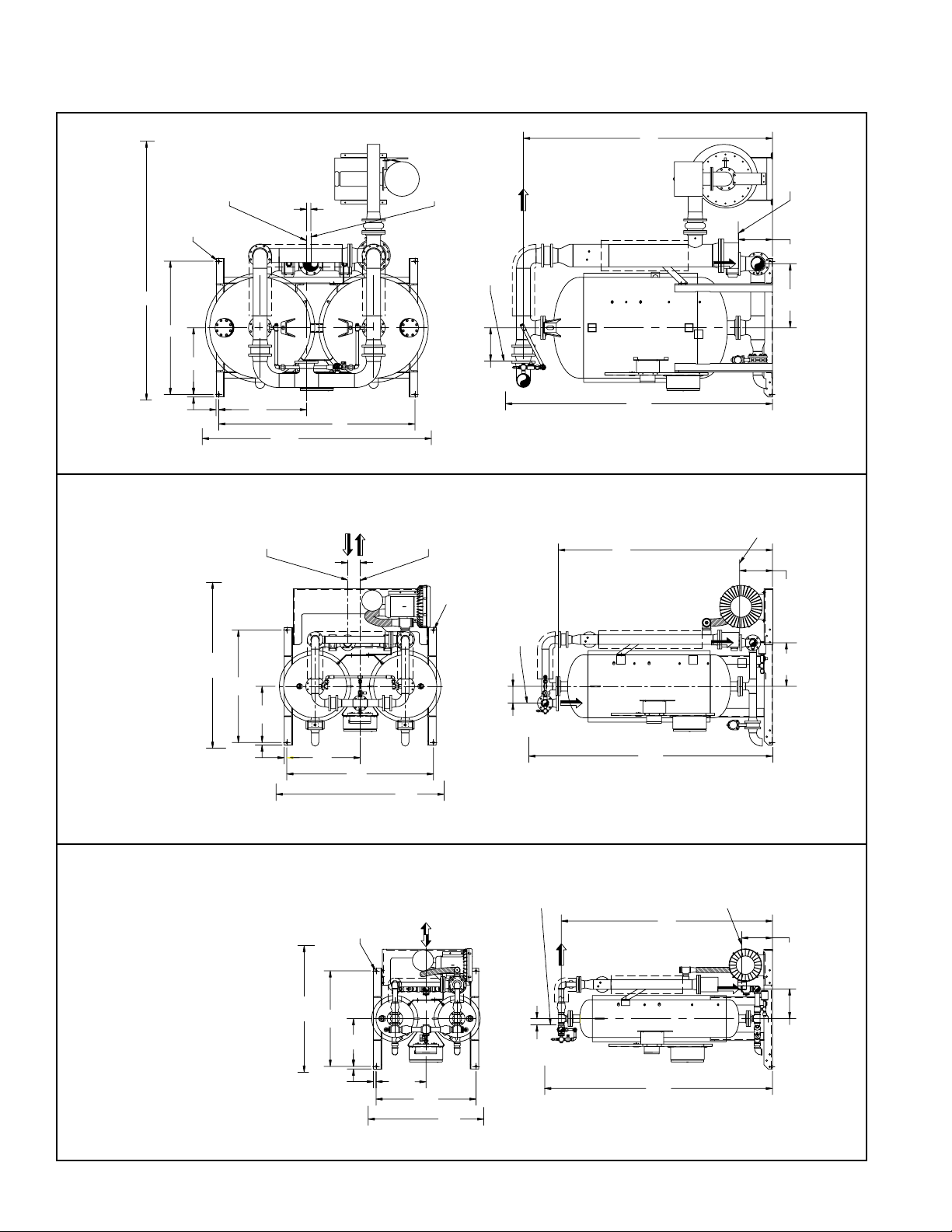
Dimensions and Connections
CENTERLINE OF
CUSTOMER DRY GAS
OUTLET CONNECTIO
N
TOP VIEW
R
SLOT
(TYP 4 PLACES
)
CENTERLINE OF
CUSTOMER WET GA
S
INLET CONNECTION
SIDE VIEW
(RIGHT CHAMBER REMOVED FOR CLARITY)
T
GAS OUTLET
E
(MAX)
F
G
C
D
B
A
(MAX)
H
K
N
(MAX)
P
L
S
GAS INLET
M
FACE OF CUSTOMER
WET GAS INLE
T
CONNECTION
FACE OF CUSTOMER
DRY GAS OUTLET
CONNECTION
R
SLOT
(TYP 4 PLACES)
TOP VIEW
SIDE VIE
W
(RIGHT CHAMBER REMOVED FOR CLARITY)
S
GAS INLET
T
GAS OUTLET
H
E
(MAX)
F
G
C
D
B
A
(MAX)
N
(MAX)
P
L
M
K
E
(MAX)
R SLOTS
(T
YP 4 PLACES)
TOP VIEW
SIDE VIEW
(RIGHT CHAMBER REMOVED FOR CLARITY)
S
AIR INLET
T
AIR OUTLET
F
C
D
B
A
(MAX)
N
(MAX)
M
L
P
K
G
Figure 2 (continued on next page)
(Contact factory to request certified drawings)
VIEW III
3200 through 4300 scfm
VIEW II
6
750 through 2600 scfm
VIEW I
500 — 600 scfm

Dimensions and Connections
Figure 2 (continued from previous page)
DIMENSIONS IN INCHES
A 53 55 60 60 64 66 80 80 85 85 85 85 109
B 46.3/4 47.9/16 52.11/16 52.11/16 56.7/16 57.5/16 69.13/16 69.13/16 73.3/8 73.3/8 82.7/8 82.7/8 93.3/8
MODEL 500 600 750 900 1050 1300 1500 1800 2200 2600 3200 3600 4300
VIEW REF. I I II II II II II II II II III III III
C 1.1/4 1.1/4 1.1/4 1.1/4 1.1/4 1.1/4 1.1/4 1.1/4 1.1/4 1.1/4 1.1/4 1.1/4 1.1/4
E 59 60 68 68 62 73 79 79 86 89 107 116 123
D 23.3/8 23.13/16 26.5/8 26.5/8 29.9/16 30 34.7/8 34.7/8 38.9/16 38.9/16 36.9/16 36.9/16 41.13/16
F 45.1/2 45.1/2 53.1/2 53.1/2 53.1/2 53.1/2 53.1/2 53.1/2 59.1/2 59.1/2 59.1/2 59.1/2 63.1/2
G 22.3/4 22.3/4 26.3/4 26.3/4 26.3/4 26.3/4 26.3/4 26.3/4 29.3/4 29.3/4 29.3/4 29.3/4 31.3/4
DIMENSIONS IN MILLIMETERS
L 12.11/16 13.3/16 13.7/16 13.7/16 13.3/16 13.3/16 15.5/8 15.5/8 17.1/4 17.1/4 14.9/16 16.9/16 16.1/4
H — — 1.1/4 1.1/4 3.1/4 3.1/4 5.15/16 5.15/16 4.3/8 4.3/8 3/4 5 2
K 3 3 8 8 8 8 8 8 7.1/4 7.1/4 15.7/8 15.7/8 15.7/8
M 96.15/16 100.7/16 100.11/16 100.11/16 99.13/16 104.13/16 101.7/8 101.7/8 115.7/8 115.7/8 115.13/16 122.1/16 118.1/2
P 13.3/16 14.3/16 15.3/4 15.3/4 16.3/4 17.3/4 20.3/4 20.3/4 22.1/4 22.1/4 26.1/2 27.1/2 30.1/2
N 105 108 114 114 113 118 116 116 128 128 128 134 130
S 2 NPT 2 NPT 3 FLANGE 3 FLANGE 3 FLANGE 3 FLANGE 3 FLANGE 4 FLANGE 4 FLANGE 4 FLANGE 4 FLANGE 6 FLANGE 6 FLANGE
R 7/8 X 1.1/4 7/8 X 1.1/4 7/8 X 1.1/4 7/8 X 1.1/4 7/8 X 1.1/4 7/8 X 1.1/4 7/8 X 1.1/4 7/8 X 1.1/4 7/8 X 1.1/4 7/8 X 1.1/4 7/8 X 1.1/4 7/8 X 1.1/4 7/8 X 1.1/4
T 2 NPT 2 NPT 3 FLANGE 3 FLANGE 3 FLANGE 3 FLANGE 3 FLANGE 4 FLANGE 4 FLANGE 4 FLANGE 6 FLANGE 6 FLANGE 6 FLANGE
WT/LBS 1,900 2,200 2,500 2,600 3,000 3,600 5,400 5,500 8,100 8,200 9,400 9,900 12,350
MODEL 500 600 750 900 1050 1300 1500 1800 2200 2600 3200 3600 4300
F 1156 1156 1359 1359 1359 1359 1359 1359 1511 1511 1511 1511 1613
A 1346 1397 1524 1524 1626 1676 2032 2032 2159 2159 2159 2159 2769
B 1187 1208 1338 1338 1434 1456 1773 1773 1864 1864 2106 2106 2372
VIEW REF. I I II II II II II II II II III III III
E 1491 1531 1734 1734 1580 1862 2009 2009 2186 2256 2708 2955 3132
C 32 32 32 32 32 32 32 32 32 32 32 32 32
D 594 604 677 677 750 761 886 886 980 980 929 929 1062
G 578 578 679 679 679 679 679 679 756 756 756 756 806
L 322 335 341 341 335 335 397 397 438 438 370 421 413
H — — 32 32 83 83 151 151 111 111 19 127 51
K 76 76 203 203 203 203 203 203 184 184 403 403 403
M 2462 2551 2557 2557 2535 2662 2588 2588 2943 2943 2942 3100 3010
N 2664 2753 2903 2903 2870 2997 2946 2946 3246 3246 3246 3404 3313
P 335 360 400 400 425 451 527 527 565 565 673 699 775
S 2 NPT 2 NPT 3 FLANGE 3 FLANGE 3 FLANGE 3 FLANGE 3 FLANGE 4 FLANGE 4 FLANGE 4 FLANGE 4 FLANGE 6 FLANGE 6 FLANGE
R 22 X 32 22 X 32 22 X 32 22 X 32 22 X 32 22 X 32 22 X 32 22 X 32 22 X 32 22 X 32 22 X 32 22 X 32 22 X 32
T 2 NPT 2 NPT 3 FLANGE 3 FLANGE 3 FLANGE 3 FLANGE 3 FLANGE 4 FLANGE 4 FLANGE 4 FLANGE 6 FLANGE 6 FLANGE 6 FLANGE
WT/KGS 862 998 1,134 1,179 1,361 1,633 2,449 2,495 3,674 3,719 4,264 4,491 5,602
7

5.0 Instrumentation
The following instrumentation helps in monitoring dryer
operation and performance. Instruments which are
available as options are so noted.
Blower Purge Air dryers are rated NEMA 4 and include
the following:
• Solid State Controls
• Chamber Pressure Gauges
• Purge Flow Pressure Gauge
• Energy Management (Option A)
• Energy Management System & Dew Point Transmitter
(Option B)
5.1 Controls
The solid-st ate dr yer co ntro ls are locat ed in a
polycarbonate, NEMA Class 4/4X, IP66 rated electrical
enclosure mounted to a center panel located between
the two desiccant towers. Control features include:
• 15 LED’s to indicate operating status and fault
conditions.
5.5 Dew Point Transmitter
This option monitors and displays outlet pressure dew
points and provides an alarm signal if the dew point
exceeds user-specified set point. Recommen ded
calibration interval is 12 months. Contact the service
department for details.
Operation – The dew point is measured at the dryer
operating pressure and is displayed in the operator
interface. If the dew point is outside of the temperature
range, the display will indicate an over-range (high
dew point) or under-range (low dew point) condition. A
defective sensor assembly or an electronics malfunction
could also cause the transmitter to indicate underrange.
• Two line text display to provide status and diagnostic
messages.
• Upon power loss, dryer “fails safe” (inlet valve
remains in position). On power recovery, controller
resumes where power was lost.
5.2 Chamber Pressure Gauges
A gauge mounted on the gauge panel indicates which
chamber is on-stream and which is regenerating. The
gauge for the onstream tower indicates operating
pressure; the gauge for the regenerating tower indicates
0 psig.
5.3 Purge Flow Pressure Gauge
A gauge mounted on the gauge panel of the dryer
indicates purge air pressure.
5.4 Energy Management System
Th e opt ional Energy Manag ement System (EMS)
automatically adjusts dryer operation to compensate
for changes in operating conditions. Air samples are
continuou sly taken from the on-stream to wer and
passed ov er a moisture probe which sense s both
temperature and relative humidity. The moisture content
of the air within the desiccant bed is then precisely
determined. The on-stream tower will not depressurize
and regenerate until a predetermined set point has been
reached. This elimination of unnecessary regeneration
reduce s energy cons ump tion and e xte nds d ryer
desiccant and component life.
8

RS232
P1
P2
PURGE INLET
CHECK VALVE
TOP VIEW
ASME RELIEF VALVE
OUTLET CHECK VALVE
DESICCANT
FILL PORT
LEFT TOWER
PRESSURE GAUGE
PRESSURE REGULATOR
& PILOT AIR FILTER
DEWPOINTER
(OPTIONAL)
TOWER PURG
E
EXHAUST VALVE
FRONT VIEW
TOWER
DEPRESS VALV
E
DESICCANT
DRAIN POR
T
TO
WER
INSULATION
(OPTIONAL
)
CONTRO
L
ENCLOSURE
HIGH TENSIO
N
ENCLOSURE
RIGHT TOWER
PRESSURE GA
UGE
PURGE
PRESSURE GAUGE
REPRESS VALV
E
HEATER TEMP
THERMOCOUPLE
(CENTER END IN PIPE)
(OPPOSITE SIDE)
HEATER OVERTEMP RTD
PURGE
HEATER WITH
INSULATION
PURGE SUCTION
FILTER SILENCER
PURGE BLOWER
AND MOTOR
REAR VIEW
TOWER INLET
VALV
E
ASME CODE TAG
HOT PIPE INSULATION
P1P
2
P3
P4
TOWER BLOWDOWN VALVE
General Layout Drawing
Figure 3
(Models 500 through 600)
9

LEFT TOWER PURGE
EXHAUST VALVE
DEWPOINTE
R
(OPTIONAL)
PRESSURE REGULATOR
& PILOT AIR FILTER
LEFT TOWER
PRESSURE GAUGE
DESICCANT
FILL PORT
LEFT OUTLET
CHECK VALV
E
PURG
E
PRESSURE GAUGE
RIGHT TOWER
PRESSURE GAUGE
CONTROL ENCLOSURE
HIGH TENSION ENCLOSUR
E
TOWER INSULATION
(OPTIONAL)
DESICCANT
DRAIN PORT
RIGHT TOWE
R
DEPRESS VALV
E
ASME RELIEF VALV
E
REPRESS VALV
E
TOP VIEW
FRONT VIEW
PURGE
HEATER WITH
INSULATIO
N
PURGE SUCTION
FILTER SILENCER
PURGE BLOWER
AND MOTO
R
REAR VIEW
LEFT TOWER
INLET VALV
E
ASME CO
DE TAG
LEFT PURGE INLE
T
CHECK VALV
E
HOT PIPE INSULATION
AIR
OUTLET
AIR
INLET
LEFT TOWER
DEPRESS VALV
E
RIGHT TOWER PURGE
EXHAUST VALV
E
RIGHT OUTLET
CHECK VALV
E
AIR
OUTLET
AIR
INLET
LEFT TOWER
PURGE EXHAUST
VALV
E
PURGE EXHAUST
RIGHT TOWE
R
PURGE EXHAUST
VALV
E
PURGE EXHAUST
TOWER BLOW
-
DOWN VALV
E
HEATER TEMP
THERMOCOUPLE
(CENTER END IN PIPE)
(OPPOSITE SIDE)
HEATER OVERTEMP RT
D
10
General Layout Drawing
(Models 750 through 2600)
Figure 3a

TOP VIEW
OUTLET
CHECK VALV
E
ASME RELIEF VALV
E
DESICCANT
FILL PORT
LEFT TOWER
PRESSURE GAUGE
PRESSURE REGULATOR
& PILOT AIR FILTER
DEWPOINTE
R
(OPTIONAL)
TOWER PURGE
EXHAUST VALV
E
FRONT VIEW
TOWER
DEPRESS VALVE
DESICCANT
DRAIN PORT
TOWER INSULATION
(OPTIONAL)
HIGH TENSION
ENCLOSUR
E
CONTROL
ENCLOSUR
E
RIGHT TOWER
PRESSURE GAUGE
PURGE PRESSUR
E
GAUGE
REPRESS
VALV
E
PURGE BLOWER
AND MOTO
R
PURGE BLOWER
THROTTLING VALV
E
PURGE SUCTION
FILTER SILENCER
PURGE HEATER
WITH INSULATION
HEATER
OVERTEMP RT
D
HOT PIPE
INSULATIO
N
PURGE INLET
CHECK VALV
E
TOWE
R
INLET VALV
E
REAR VIEW
HEATER TEMP
THERMOCOUPLE
(CENTER END IN PIPE
)
(OPPOSITE SIDE
)
CHAMBER
BLOW-DOWN
VALV
E
Figure 3b
General Layout Drawing
(Models 3200 through 4300)
11

6.0 Operation
6.1 Controls
A solid-state controller controls valve and heater operation, monitors all critical operating conditions, and indicates operating status on a 2-line LCD display operator
interface. The controller receives input data from pressure switches, temperature sensors and the operator
interface. The operator interface displays information
about the dryer operating status and is used to change
the dryer operating mode.
6.2 Operating Modes
6.2.1 Automatic and Manual Advance
The drying and regeneration cycles are divided into
discrete steps. The operator selects either one of the
automatic advance modes (Energy Management, Dew
Point Control, or Fixed Cycle) or manual advance mode
(Test Cycle) through the operator interface.
Selecting any of the automatic advance modes enables
a timer in the controller to advance the program step-bystep according to the programmed schedule.
Setting up the controller for manual advance disables the
timer and the operator can advance the program one step
at a time. This mode is used for diagnostic purposes.
6.2.2 Fixed, Energy Management or Dew Point
Control Operation
The operator interface is used to select either Fixed,
Energy Management or Dew Point Control operation. In
Fixed Cycle operation, each tower is on-line (drying) for a
fixed time period regardless of the operating conditions.
In Energy Management or Dew Point Control operation,
a tower remains on-line until the desiccant bed has been
fully utilized. For lower than designed moisture loads,
this results in longer drying cycles, longer time between
regenerations and, therefore lower energy consumption.
Energy Management or Dew Point Control operation
are optional features.
6.3 Operating Sequence Description
1. Left Tower Drying – Right Tower Regenerating
At the start of the Left Tower Drying cycle, Left Inlet
Valve V1 opens, Right Inlet Valve V2 closes to isolate the two towers. Wet, compressed air flows up
through the left tower where it is dried. The dry air
exits the dryer through the Left Outlet Check Valve
V7.
Next, the Right Depressurization Valve V10 is
opened and the right tower is slowly depressurized.
Air exits through exhaust muffler M2.
After the right tower has depressurized, the Right
Purge Valve V4 is opened and the Blower M and
Heater H1 are energized. The heated air flows
through the Right Purge Check Valve V6, down
through the right tower, and exits through the Right
Purge Valve V4. The Blower intake air is filtered
to keep dust and dirt from entering the dryer. The
Blower M and Heater H1 are de-energized when
the temperature at the bottom of the right tower,
as sensed by the Right Tower Temperature Sensor
RTD2, reaches the Heat Termination set point. This
indicates that the bed has been fully heated.
Note: Blower will continue to run briefly at the end
of the Heating Step to sweep residual heat from the
heater.
The Repressurization Valve V11 is opened. A portion
of the dry air from the left tower now flows through
Repressurization Valve V11. This air is throttled to
near atmospheric pressure by Repressurization/
Sweep Orifice O2. The dry, low pressure air flows
down through the right tower cooling the desiccant
bed, and exits through the Right Tower Purge Exhaust Valve V4.
The Cooling Step continues until:
a) the right tower bed temperature falls to 150°F
or,
b) it is time to repressurize the right tower,
whichever occurs first.
Note: In fixed cycle, the bed will normally be partially
cooled because the repressurization step will occur
before the bed temperature can fall to 150°F.
Note: In Energy Management or Dew Point Control,
as the drying time extends beyond 4 hours, additional
cooling time becomes available thus the cooling
step will frequently terminate based on temperature
providing complete bed cooling.
At the end of the Cooling Step, the Right Tower Purge
Exhaust Valve V4 is closed. The right tower slowly
repressurizes to full line pressure and is ready to go
back on-line.
Note: Bed cooling can be disabled by moving JP4
to the “ON” position.
2. Right Tower Drying – Left Tower Regenerating
At the start of the Right Tower Drying cycle, Right
Inlet Valve V2 opens, Left Inlet Valve V1 closes to
isolate the two towers. Wet, compressed air flows
up through the right tower where it is dried. The dry
air exits the dryer through the Right Outlet Check
Valve V8.
Next, the Left Depressurization Valve V9 is opened
and the left tower is slowly depressurized. Air exits
through exhaust muffler M1.
12
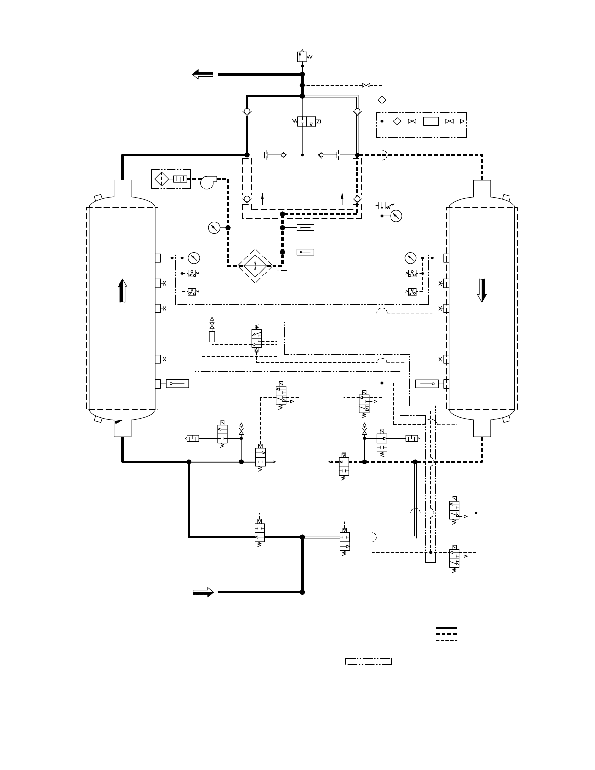
WET GAS
INLET
DRY GA
S
OUTLET
SOL 'D'
V1
SOL 'F'
M1
V9
RTD
1
V3
V4
V2
SOL 'B
'
M2
SOL 'A
'
SOL 'G'
V1
0
RTD
2
V6
1PS
(RTD4/HS1)
ENERGY MGMT OPTION
SET @ 176°F
DRYING
EXH.
3PS
SET
@
5 PSIG
SOL 'C'
2
1
3
LEFT
TOWER
SET
@
45 PSI
G
M
RTD
3
SET @ 650°F
1T
C
SET @ 370°F
V5
2P
S
SET @ 176°F
4P
S
SET
@
5 PSI
G
REGE
N
SET
@
45 PSIG
SET AT
100 PSIG
RIGH
T
TOWE
R
V8
V12 V13
SOL 'E'
V7 V11
RV
1
SET @ 165 PSI
G
DEWPOINTER OPTION
DP
A
SOLENOID VA
LVES 'B', 'D', & 'G' ARE SHOWN ENERGIZED,
SYMBOLS ARE PER ANSI Y32.10 "GRAPHIC SYMBOLS FOR FLUID POWER DIAGRAMS."
SOLENOID VA
LVES 'A', 'C', 'E', & 'F' ARE SHOWN DE-ENERGIZED.
AS SHOWN FLOW DIRECTION IS:
INDICATES OPTION
3.
2.
1.
PILOT GAS LINE
RIGHT CHAMBER REGEN
LEFT CHAMBER DRYING
NOTES
4.
BD2BD1
H1
PI3
PI1
PI2
F1
PR&G
F2
O2
V1
4
O1
Figure 4
Sequence of Operation — Fixed Cycle Operation
Left Chamber Drying – Right Chamber Regenerating (shown)
(continued on next page)
13

After the left tower has depressurized, the Left Purge
P
EM
S
LEFT
TOWER
RIGHT
TOWER
Valve V3 is opened and the Blower M and Heater
H1 are energized. The heated air flows through the
Left Purge Check Valve V5, down through the left
tower, and exits through the Left Purge Valve V3.
The Blower intake air is filtered to keep dust and dirt
from entering the dryer. The Blower M and Heater
H1 are de-energized when the temperature at the
bottom of the left tower, as sensed by the Left Tower
Temperature Sensor RTD1, reaches the Heat Termination set point. This indicates that the bed has
been fully heated.
The Repressurization Valve V11 is opened. A portion
of the dry air from the right tower now flows through
Repressurization Valve V11. This air is throttled to
near atmospheric pressure by Repressurization/
Sweep Orifice O1. The dry, low pressure air flows
down through the left tower cooling the desiccant
bed, and exits through the Left Tower Purge Exhaust
Valve V3.
The Cooling Step continues until:
a) the left tower bed temperature falls to 150°F
or,
b) it is time to repressurize the left tower,
whichever occurs first.
6.3.1 Energy Management Control (optional)
Operation of the Energy Management Control cycle is
identical to the fixed cycle except the cycle is extended
until the desiccant bed in the on-line tower has been fully
utilized. The off-line tower is regenerated and remains
in a stand-by mode after being repressurized.
Figure 5 shows the air sampling system for the Energy
Management System – EMS option. A 3-way pilot valve
directs an air sample from the drying tower to the EMS
sensor. The EMS sensor detects the relative humidity
and temperature of the air sample. The air sample then
exhausts to atmosphere. The drying tower remains online until the moisture front arrives at the sensor.
Note: In fixed cycle, the bed will normally be partially
cooled because the repressurization step will occur
before the bed temperature can fall to 150°F.
Note: In Energy Management or Dew Point Control,
as the drying time extends beyond 4 hours, additional
cooling time becomes available thus the cooling
step will frequently terminate based on temperature
providing complete bed cooling.
At the end of the Cooling Step, the Left Tower Purge
Exhaust Valve V3 is closed. The left tower slowly
repressurizes to full line pressure and is ready to go
back on-line.
Note: Bed cooling can be disabled by moving JP4
to the “ON” position.
Figure 5
Optional Moisture Sensing
Energy Management System (EMS)
14

6.4 Control Board Jumpers
In the upper left hand corner of the control board there
are eight two-pin jumpers labeled JP1 through JP8. Only
five of the eight jumper pairs are utilized. Pairs JP6-JP8
are used for factory settings and testing. NOTE: Do
not install jumpers in the ON position on pairs JP6
through JP8. The jumper is a removable bridge that is
used to make or break continuity between two pins that
form a pair. When installed in the ON position, the jumper
is place on both pins of the pair and continuity between
the pins is established. When installed in the OFF position, the jumper is removed or stored on a single pin and
continuity is broken. Jumper functions are as follows:
1. JP1 – Dryer Type
Jumper JP1 is used to select the dryer type configu-
ration. It is installed in the ON position for Blower
Purge dryer configuration.
2. JP2 – Energy Management
Jumper JP2 is installed in the ON position when an
Energy Management sensor is installed. The jumper
is installed in the OFF position when no Energy
Management sensor is installed.
3. JP3 – Dew Point Transmitter
Jumper JP3 is installed in the ON position when a
Dew Point Transmitter is installed. The jumper is
installed in the OFF position when no Dew Point
Transmitter is installed.
NOTE: “Energy Management” can co-exist with the
dew point transmitter option. Dryer control based
on the ENERGY MANAGEMENT or DEWPOINT
CONTROL is selected on Screen 1 of the Set Up
Mode.
If DEWPOINT CONTROL is not selected then the
dew point signal does not control the dryer cycle but
still serves a monitoring and alarm function.
8. JP8 – Set Up
Jumper JP8 is factory installed in the OFF position
to disable access to “factory” set up screens. The
jumper is installed in the ON position during final
inspection at the factory to set controller to match
customer requirements.
6.5 Operator Interface
Refer to Figure 6 , Front Panel Overlay for information
regarding the location and function of the LEDs, switches,
and text display.
6.5.1 Front Panel LED’s
• Power On - green
• Alarm - red
• Service / Maintenance reminder - amber
• Filters (pre, after, and pilot) service / maintenance
reminders - amber
• Inlet switching and purge / repressurization valve status (On = valve open; Off = valve closed) - green
• Left and right tower status (heating) - amber
• Left and right tower status (drying) - green
• Left and right tower pressure switch status (On =
switch closed; Off = switch open) - green
6.5.2 Front Panel Switches
The front panel contains four momentary-contact pushbutton switches. Refer to Figure 6, Front Panel Overlay
for the appropriate icon associated with each switch.
Pushing on the overlay icon actuates the switch.
Data Display Switch
Th is switch is used to step th rough the display
screens.
Select Switch
This button is located to the left of the text display window.
Refer to the Front Panel Operation Section for additional
information.
4. JP4 – Cooling Cycle
Jumper JP4 is installed in the ON position to disable
the Cooling Cycle. The jumper is installed in the OFF
position to enable a Cooling Cycle.
5. JP5 – Switching Failure
Jumper JP5 is installed in the ON position to enable
Switching Failure. The jumper is installed in the OFF
position if Switching Failure is disabled.
6. JP6 – Not Used
NOTE: Jumpers JP7 and JP8 are used by the factory
during final inspection to download language text and to
enable ‘factory’ set-up screens.
7. JP7 – Download Language Text
Jumper JP7 is factory installed in the OFF position
to disable Language Text download. The jumper is
installed in the ON position to allow for language text
download due to either language corrections or new
language installation.
ENTER Switch
This button is located to the right of the text display
window. Refer to the Front Panel Operation Section for
additional information.
Alarm Reset Switch
This button is normally used to reset an alarm or service
reminder. Refer to the Front Panel Operation Section
for additional information.
15

Left Tower Drying LED
Left Purge Valve LED
On=valve open
Off=valve closed
Left Inlet Valve LED
On=valve open
Off=valve closed
Left Tower
Heating LED
Filter Service /
Maintenance LED
Vacuum Fluorescent
Text Display
Select switch
Power On LED
Data Display Switch
Communications Icon
Filter Service /
Maintenance LED
Filter Service /
Maintenance LED
Right Tower Pressure
Switch LED:
On=Tower pressurized
Right Tower Drying LED
Right Purge Valve LED
On=valve open
Off=valve closed
Right Tower
Heating LED
Right Inlet Valve LED
On=valve open
Off=valve closed
Enter Switch
Maintenance / Service
Reminder LED
Alarm LED
Reset Switch for Alarm
Left Tower Pressure
Switch LED:
On=Tower Pressurized
RS232
6.5.3 Front Panel Operation
1. There are five operating modes for the Heated
Desiccant Dryer Control.
a. Program Mode
b. Setup Mode
c. Alarm & Service Mode
d. Display Mode
e. Test Mode
2. Each Mode is described below.
6.5.4 Program Mode
1. Press and hold and for 3 seconds to enter
Program Mode.
2. Program Mode is comprised of the screens that are
described below.
3. There are three (3) ways to exit Program Mode.
a. Press after making the selection in the final
b. At any screen, press and hold for 3 sec-
c. The controller automatically exits Program Mode
16
screen.
onds.
if no button is pressed within 60 seconds.
Figure 6
Front Panel Overlay
4. Upon exiting Program Mode the controller will switch
Screen 1: Select the Language
1. Press to scroll through the choices: ENGLISH,
2. When finished, press to save the selection and
Screen 2: Select the Service Level
1. Pr ess to toggle bet w een N ORMA L and
to Display Mode.
ENGLISH
FRANCAIS and ESPANOL.
move to next screen.
SERVICE LEVEL
NORMAL
SEVERE.
a. NORMAL Service Intervals are:
i. 4000 hours for filters
ii. 8000 hours for desiccant
iii. 8000 hours for valves

b. SEVERE Service Intervals are:
i. 2000 hours for filters
ii. 4000 hours for desiccant
iii. 4000 hours for valves
2. When finished, press to save the selection and
move to next screen.
Screen 3: Reset the Timer for Filter Service
FILTER SERVICE
RESET? NO
1. Press to toggle between NO and YES.
2. When finished, press to acknowledge the
selection and move to next screen.
Screen 4: Reset the Timer for Desiccant Service
DESICCANT SERVICE
RESET? NO
1. Press to toggle between NO and YES.
2. When finished, press to acknowledge the
selection and move to next screen.
Screen 5: Reset the Timer for Valve Service
VALVE SERVICE
RESET? NO
Screen 7: Set Point for Dew Point Demand Control
(Displayed only when JP3 “on”)
DPNT CNTL SETPT
±XX°C ±XXX°F
1. Press to increment the setting to the desired
value.
a. Standard set point is
-30°C -22°F
.
b. The allowable range of values is from
-80°C -112°F
+10°C +50°F
to
in 5°C/9°F
increments.
Note: Must be set “drier” than Dew Point Sensor
Alarm Set Point (screen 6).
2. When finished, press to acknowledge the
selection and exit the Program Mode.
Screen 8: Set the Heat Termination Set Point
HEAT TERM SET-PT
XX°C XXX°F
1. Press to increment the setting to the desired
temperature value.
a. Refer to P&ID diagrams in the back of this manual
for Heat Termination set points (see set point
values for RTD1 and RTD2).
b. The allowable range of values are:
60° - 160°C 140° - 320°F
in 10°C increments.
1. Press to toggle between NO and YES.
2. When finished, press to acknowledge the selection and move to next screen.
Screen 6: Set Alarm Point for the Dew Point
Sensor (Displayed only when JP3 “on”)
DEWPOINT ALARM
±XX°C ±XXX°F
XX MIN SW DELAY
1. Press to increment the setting to the desired
value.
a. Standard set point is
-20°C -4°F
.
b. Th e a l l o w a b l e r a n g e o f v a l u e s i s f r o m
-80°C -112°F
+10°C +50°F
to
in 5°C/9°F
increments.
2. When finished, press to acknowledge the selection and scroll to the switchover delay set point
screen.
a. Standard set point is
b. The allowable range of values are
60 MIN
.
30 to 120 MIN
in 10 minute increments.
3. When finished, press to acknowledge the selection and move to next screen. Exit Program Mode
when there are no more active screens to display.
2. When finished, press to acknowledge the selection and move to next screen. Exit Program Mode
when there are no more active screens to display.
Screen 9: Set Points for Energy Management
(Displayed only when JP8 “on”)
ENRGY MGMT SETPT
XX%RH
XX MBAR .XXX PSI
1. Press to increment the setting to the desired
maximum RH value.
a. Factory set point is
60%RH
. The factory setting
should not require adjustment.
b. The allowable range of values are
20 to 80%RH
in 5% increments.
2. When finished, press to acknowledge the selection and scroll to the pressure set point screen.
3. Press to increment the setting to the desired
maximum vapor pressure value.
a. Standard set point for a -40°F dew point dryer
16 MBAR (0.232 PSI)
.
is
Note: Standard set point for a -100°F dew point
dryer
b. The allowable range of values
3 to 34 MBAR (0.044 to 0.493 PSI)
4 MBAR (0.058 PSI)
is
.
in
is
1 MBAR
increments.
17

c. This setting may be field adjusted to increase or
decrease the outlet dew point at tower switchover.
4. When finished, press to acknowledge the selection and move to next screen.
Screen 10: Set Points for High Humidity Alarm
(Displayed only when JP8 “on”)
HIGH HUMIDITY
XX%RH
XX MBAR .XXX PSI
XX MIN SW DELAY
1
. Press to increment the setting to the desired
maximum RH value.
a. Factory set point is
75%RH
. The factory setting
should not require adjustment.
b. The allowable range of values are
20 TO 80%RH
in 5% increments.
Note: Value must be set above Energy Manage-
ment Maximum RH Value Set Point (screen 9).
6.5.5 Setup Mode
1. Press and hold for 3 seconds to enter Setup
Mode.
2. Setup Mode is comprised of the screens that are
described below.
3. There are two ways to exit Setup Mode.
a.
Press after making the selection in Screen 1.
b. The controller automatically exits Setup Mode if
no button is pressed with 60 seconds.
4. One of two things will happen upon exiting Setup
Mode.
a. The controller will switch to Display Mode if
ENERGY MANAGEMNT, FIXED CYCLE or
DEWPOINT CONTROL is selected.
b. The controller will switch to Test Mode if TEST
CYCLE is selected.
Screen 1: Select the Cycle Type
CYCLE TYPE
ENERGY MANAGEMNT
2. When finished, press to acknowledge the selection and scroll to the pressure set point screen.
3. Press to increment the setting to the desired
maximum vapor pressure value.
a. Factory set point for a -40°F dew point dryer is
24 MBAR (0.348 PSI)
.
Note: Factory set point for a -100°F dew point
dryer is
5 MBAR (0.073 PSI)
.
b. The allowable range of values is
3 to 34 MBAR (0.044 to 0.493 PSI)
in 1 MBAR incre-
ments.
Note: Value must be set above Energy Man-
agement Maximum Vapor Pressure Set Point
(screen 9).
4. When finished, press to acknowledge the selection and scroll to the switchover delay set point
screen.
a. Factory set point is
b. The allowable range of values are
60 MIN.
.
30 to 120 MIN
in 10 minute increments.
5. When finished, press to acknowledge the selection and move to next screen. Exit Program Mode
when there are no more active screens to display.
1. Press to scroll through the choices:
a. ENERGY MANAGEMNT (displayed only when
JP2 is in the ON position)
b. DEWPOINT CONTROL (displayed only when JP3
is in the ON position)
c. FIXED CYCLE
d. MANUAL CYCLE
2. When finished, press to save the selection and
exit the Setup Mode.
18

6.5.6 Alarm & Service Mode
1. Alarm & Service Mode is active when the controller
is in Display Mode. It is not active in Program Mode,
Setup Mode, or Test Mode.
2. Local alarm consists of a blinking alarm LED and an
alarm message display.
3. Alarm messages have prior ity over Se rvice
messages. Service messages have priority over
Display Messages.
4. After an alarm condition has been corrected, if:
a. Alarm is “self-clearing” then,
i. The alarm LED stops blinking (LED on); the
alarm message continues to be displayed.
ii. The alarm reset button must be depressed to
clear the alarm LED (LED off) and the alarm
message.
b. Alarm must be manually reset, then:
i. The alarm LED continues to blink and the
alarm message continues to be displayed.
ii. The alarm reset button must be depressed
to:
1. Clear the alarm LED (LED off)
2. Clear the alarm message and
3. Restart the dryer cycle.
5. When an alarm condition has not been corrected
and the “alarm reset” button is pressed, the alarm
will not clear except as follows:
a. The alarm conditions will clear for 5 seconds,
then reappear if the alarm condition persists, this
applies to the following alarms:
i. Heater: High Inlet Temperature.
ii. Heater: Low Temperature
iii. Humidity Sensor: High Humidity Alarm
iv. Humidity Sensor: Under-Range or Over-
Range Alarm
v. Dew Point Sensor: High Dew Point Alarm
vi. Dew Point Sensor: Under-Range or Over-
Range Alarm
6. There are three alarms for each tower that are
triggered by the tower pressure switches. These
alarms can occur in any operating mode (Manual,
Fixed, Energy Management, or Dew Point Demand
Cycle).
Following is a brief description of each alarm.
a. Left or Right tower, drying, low pressure
i. Drying tower pressure switch is open during
the drying cycle.
b. Left or Right tower, regenerating, high pressure
i. Regenerating tower pressure switch is closed
while purge valve is open (after an initial time
delay).
c. Left or Right tower, regenerating, low pressure
i. Regenerating tower pressure switch is open
at the end of the regenerating cycle.
d. On alarm condition, the blower and heater are
de-energize, the cycle sequence is stopped, a
local alarm is displayed and the common alarm
relay is de-energized.
e. These alarms are self-clearing.
7. Heater High Inlet Temperature
a. Model sizes 3200, 3600 and 4300 are equipped
with a temperature switch located in the piping
between the blower and heater.
b. If during the Heat Cycle this temperature switch
opens, indicating a rise in temperature above
the factory setting (refer to Electrical Schematic
drawings at the back of this manual for set point),
an alarm is activated.
c. On alarm condition, the blower and heater are
de-energized, the cycle sequence is stopped, a
local alarm is displayed and the common alarm
relay is de-energized.
d. This alarm must be manually reset.
8. The dryer is equipped with RTD temperature sensors.
There are out of range alarms for each.
a. The standard left tower, right tower, and heater
RTDs (RTD1, RTD2, RTD3) are scaled from
-20°F(-28°C) to 890°F (477°C), “Out of Range”
conditions are as follows:
i. Over-range - temperature abov e 850°F
(454°C)
ii. Under-range - temperature below -20°F
(-28°C)
iii. Note: The controller will annunciate a “Heater
Overtemperature” alarm in lieu of an “Over
Range” alarm when the heater sensor is
disconnected.
b. The Energy Management RTD4 is scaled from
-20°F(-28°C) to 429°F(220°C), “Out of Range”
conditions are as follows:
i. Over-range - temperatures above 400°F
(204°C)
ii. Under-range - temperatures below -20°F (-
28°C)
c. On alarm condition, a local alarm is displayed and
the common alarm relay is de-energized.
d. Over-range and Under-range alarms are self-
clearing.
19

ALARM MESSAGES
LEFT TOWER ALARMS RIGHT TOWER ALARMS OTHER ALARMS
ALARM LEFT TOWER
DRYING
LOW PRESSURE
ALARM LEFT TOWER
REGENERATING
HIGH PRESSURE
ALARM LEFT TOWER
REGENERATING
LOW PRESSURE
ALARM LEFT TOWER
TEMP UNDER-RANGE
ALARM LEFT TOWER
TEMP OVER-RANGE
ALARM LEFT TOWER
OUTLET DEW POINT
ALARM RIGHT TWR
DRYING
LOW PRESSURE
ALARM RIGHT TWR
REGENERATING
HIGH PRESSURE
ALARM RIGHT TWR
REGENERATING
LOW PRESSURE
ALARM RIGHT TWR
TEMP UNDER-RANGE
ALARM RIGHT TWR
TEMP OVER-RANGE
ALARM RIGHT TWR
OUTLET DEW POINT
ALARM HEATER
OVER-TEMPERATURE
ALARM HEATER
LOW TEMPERATURE
ALARM ENRGY MGNT
UNDER-RANGE
ALARM ENRGY MGNT
OVER-RANGE
ALARM BLOWER
MOTOR OVERLOAD
ALARM HEATER
HIGH TEMP IN
ALARM LEFT TOWER
HIGH HUMIDITY
ALARM LEFT TOWER
DEW POINT
UNDER-RANGE
ALARM LEFT TOWER
DEW POINT
OVER-RANGE
ALARM RIGHT TWR
HIGH HUMIDITY
ALARM RIGHT TWR
DEW POINT
UNDER-RANGE
ALARM RIGHT TWR
DEW POINT
OVER-RANGE
20

9. Heat Low Temperature
a. RTD3 is used to detect Heater Low Tempera-
ture.
b. Alarm if the heater temperature is less than 250°F
(121°C) within 15 minutes after the Heat Cycle is
initiated (15 minute delay also applies after power
recovery).
c. On alarm condition, display local alarm and de-
energize common alarm relay.
d. This alarm is self-clearing.
10. Heater Over-Temperature
a. RTD3 is used to detect Heater Over-Tempera-
ture.
b. Alarms anytime that the Heater temperature
exceeds 650°F (343°C).
c. On alarm condition, de-energize heat cycle, stop
cycle sequence, display local alarm and de-energize common alarm relay.
d. This alarm must be manually reset.
11. Blower Overload
a. Alarm condition when blower overload contact
closes.
13. Dew Point Sensor
a. High Dewpoint Alarm
i. The user enters an alarm value through the
Program Mode.
ii. If the measured dew point exceeds the alarm
value, the outlet dew point alarm is indicated.
b. Under-range alarm - Dew point below -148°F
(-100°C)
c. Over-range alarm - Dew point greater than
+109°F (+43°C)
d. On alarm condition,
i. Local alarm is displayed and the common
alarm relay is de-energized.
ii. If dryer is set up for Dewpoint Control, the dryer
sequence continues, but bypasses the “HOLD”
step and proceeds to tower switchover after 4
hours of drying.
iii. This alarm is self-clearing, at which time the
alarm LED stops blinking and control switches
back to Dewpoint Control.
b. On alarm condition, de-energize heat cycle, stop
cycle sequence, display local alarm and de-energize common alarm relay.
c. This alarm must be manually reset.
Alarms for Optional Devices
12. Energy Management a. High Humidity Alarm:
i. Measured moisture level exceeds the air alarm
value entered through the Program Mode.
b. Humidity Sensor:
i. Under-range: RH% < -15%
ii. Over-range: RH% > 115%
c. RTD:
i. Over-range: Temperature above 448°F
(231°C)
ii. Under-range: Temperature below -20°F
(-28°C)
d. On alarm condition:
i. Local alarm is displayed and the common
alarm relay is de-energized.
ii. If the dryer is set up for Energy Management
Control, the dryer sequence continues, but
bypasses the “HOLD” step and proceeds to
tower switchover after 4 hours of drying.
iii. This alarm is self-clearing, at which time the
alarm LED stops blinking and control switches
back to Energy Management control.
21

Service Due Messages
14. There are two service levels (normal and severe)
as described in Program Mode. Each service level
has preset time intervals for servicing the filters,
desiccant, and valves. Time continues to accumulate
as long as power is supplied to the controller, whether
the controller is switched on or off.
When a service time interval expires (see also 14.d
below), the controller operates as follows.
a. The service LED blinks and the appropriate
service message is shown on the text display.
i. When the service interval for filters has expired
(see also d below), the three filter LED’s also
blink.
b. The dryer continues to cycle normally. The LED’s
for the valve’s, pressure switches, and desiccant
towers are not used for service indication.
c. Press the Reset button to extinguish the service
LED and to clear the service message from the
text display.
d. If the dryer has 1 or 2 filter monitors, the timer
for filter service is disabled. When the filter
monitor(s) send an alarm signal (change filter)
to the controller, the controller displays the same
LED’s and messages it would if the timer for filter
service had expired.
6.5.7 Display Mode
1. Display Mode is active when the user exits Program
Mode or Setup Mode and no alarms are active
(unless MANUAL CYCLE was selected in Setup
Mode).
2. Display Mode is comprised of dryer status screens
and dryer display screens (described below). The
controller automatically alternates the display
between the Status Screens and selected Display
Screens.
3. The user can override the automatic screen scroll
by pressing to step through each of the Display
Screens shown on the next page. Automatic
scrolling will resume when is pressed or if
not depressed for 60 seconds.
4. The Ene rgy Sa vings and Service Reminders
Display Screens (Filters, Desiccant, and Valves) are
alternated in sequence with the current dryer status
screen.
15. Examples of the text display are shown on page 18
and below for each alarm and service reminder. The
second line of the alarm screens contains up to three
messages which are scrolled through, displaying
each one for 2 seconds.
SERVICE DUE MESSAGES
SERVICE DRYER
FILTERS
SERVICE DRYER
DESICCANT
SERVICE DRYER
VALVES
22
DRYER STATUS SCREENS
LEFT TOWER DRYING
LT DRYING
RT DEPRESSURIZE
LT DRYING
RT HEATING
LT DRYING
RT COOLING
LT DRYING
RT REPRESSURIZE
LT DRYING
RT HOLDING
(Not displayed in FIXED Cycle)
TOWER SWITCHOVER TOWER SWITCHOVER
RIGHT TOWER DRYING
LT DEPRESSURIZE
RT DRYING
LT HEATING
RT DRYING
LT COOLING
RT DRYING
LT REPRESSURIZE
RT DRYING
LT HOLDING
RT DRYING
(Not displayed in FIXED Cycle)
Energy Savings
(Not displayed in FIXED Cycle)
ENERGY SAVINGS
XX%
Note: Energy Savings will appear
after seven days of continuous use.
Service reminder (filters)
HOURS TO SERVICE
FILTERS: XXXX
Service reminder (desiccant)
HOURS TO SERVICE
DESICCANT: XXXX
Service reminder (valves)
HOURS TO SERVICE
VALVES: XXXX
DRYER DISPLAY SCREENS
Outlet Dew Point
(Displayed only if JP3 is ON)
DEW POINT
±XX°C ±XXX°F
Left Tower Temperature
LT TEMP
±XX°C ±XXX°F
Right Tower Temperature
RT TEMP
±XX°C ±XXX°F
Heater Temperature
HEATER TEMP
±XX°C ±XXX°F
Dewpoint Demand SetPoint
(Displayed only if JP3 is ON)
DWPT CNTL SETPT
±XX°C ±XXX°F
Energy Mgmt Signal
(Displayed only if JP2 is ON)
ENERGY MGMT SGNL
XX%RH XXX°F XX°C
XX MBAR X.XX PSI
Energy Mgmt Setpoint
(Displayed only if JP2 is ON)
ENERGY MGMT SET
XX MBAR X.XX PSI
(This is the calculated “hold” set-point,
which is based on the sample air temperature.)
23

6.5.8 Test Mode
1. Test Mode is active when the user exits Program
5. Upon entering Test Mode, the program can be at any
one of the ten steps.
Mode after selecting operation in MANUAL CYCLE.
6. To exit Test Mode:
a. Press and hold for 3 seconds to exit Test
2. Test Mode is comprised of ten (10) screens (screen
descriptions follow the table below on the next page).
Each screen corresponds to one of ten program
steps (described in the table below).
3. Press to advance from one screen (test step) to
the next.
Mode. The display switches to Screen 2 of Setup
Mode.
b. Use to select ENERGY MANAGEMENT,
DEWPOINT CONTROL or FIXED CYCLE.
c. Press and hold for 3 seconds to exit Setup
Mode and activate Display Mode.
d. Dryer operation continues from the last step active
IMPORTANT: Be sure to read and understand all
when exiting the Test Mode.
cautions listed with the screen (program step) descriptions.
4. If the temperature is out of range, the second line of
the display will read “OVER-RANGE” or “UNDERRANGE” instead of the temperature reading. (Refer
to screens 2, 3, 4, 6, 7, and 8.)
Program Step 1 2 3 4 5 6 7 8 9 10
LT status Drying Drying Drying Drying Drying Off Depress Heat Cool Repress
RT status Off Depress Heat Cool Repress Drying Drying Drying Drying Drying
1PS Closed Closed Closed Closed Closed Closed
2PS Closed
3PS Closed Closed Closed Closed Closed Closed
4PS Closed
LT drying solenoid (B) On On On On On Off Off Off Off Off
LT depress solenoid (F) Off Off Off Off Off Off On On On Off
LT purge solenoid (C) Off Off Off Off Off Off Off On On Off
RT drying solenoid (A) Off Off Off Off Off On On On On On
RT depress solenoid (G) Off On On On Off Off Off Off Off Off
RT purge solenoid (D) Off Off On On Off Off Off Off Off Off
LT inlet valve (V1) Open Open Open Open Open Closed Closed Closed Closed Closed
LT depress valve (V9) Closed Closed Closed Closed Closed Closed Open Open Open Closed
LT purge valve (V3) Closed Closed Closed Closed Closed Closed Closed Open Open Closed
RT inlet valve (V2) Closed Closed Closed Closed Closed Open Open Open Open Open
RT depress valve (V10) Closed Open Open Open Closed Closed Closed Closed Closed Closed
RT purge valve (V4) Closed Open Open Open Closed Closed Closed Closed Closed Closed
Repress valve (V11) Open Closed Closed Open Open Open Closed Closed Open Open
Temp display - location Left Right Right Right Right Right Left Left Left Left
Closed
then Open
Closed
then Open
Open Open
Open Open
Open then
Closed
Open then
Closed
Closed Closed Closed Closed Closed
Closed Closed Closed Closed Closed
Closed
then Open
Closed
then Open
Open Open
Open Open
Open then
Closed
Open then
Closed
24
Table 2
Cycle Sequence Steps

TEST MODE SCREENS
Screen 1: Step 1
TEST1: LT DRYING
LT: XX°C XXX°F
Screen 2: Step 2
TEST2: DEPR RT
RT: XX°C XXX°F
Note: Sequence step will not advance to HEAT
until depressurization time has elapsed and
tower has fully depressurized. Exception: If
switching failure is disabled then pressure
condition is ignored.
Screen 3: Step 3
TEST3: HEAT RT
RT: XX°C XXX°F
To prevent bed over-heating in test mode: If the
RT temperature > heat termination set point, then
Screen 3 will display for a maximum of 1 minute
before automatically advancing to next step.
Screen 6: Step 6
TEST6: RT DRYING
RT: XX°C XXX°F
Screen 7: Step 7
TEST7: DEPR LT
LT: XX°C XXX°F
Note: Sequence step will not advance to HEAT
until depressurization time has elapsed and
tower has fully depressurized. Exception:
If switching failure is disabled then pressure
condition is ignored.
Screen 8: Step 8
TEST8: HEAT LT
LT: XX°C XXX°F
To prevent bed over-heating in test mode: If the
LT temperature > heat termination set point, then
Screen 8 will display for a maximum of 1 minute
before automatically advancing to next step.
Screen 4: Step 4
TEST4: COOL RT
LT: XX°C XXX°F
If the RT temperature < cool termination set point,
then Screen 4 will display for a maximum of 1 minute
before automatically advancing to next step.
Screen 5: Step 5
TEST5: REPR RT
LT: XX°C XXX°F
Note: Sequence step will not advance to tower
SWITCHOVER until repressurization time
has elapsed and tower has fully pressurized.
Exception: If switching failure is disabled
then pressure condition is ignored.
Screen 9: Step 9
TEST9: COOL LT
LT: XX°C XXX°F
If the LT temperature < cool termination set point,
then Screen 9 will display for a maximum of 1 minute
before automatically advancing to next step.
Screen 10: Step 10
TEST10: REPR LT
LT: XX°C XXX°F
Note: Sequence step will not advance to tower
SWITCHOVER until repressurization time
has elapsed and tower has fully pressurized.
Exception: If switching failure is disabled
then pressure condition is ignored.
25

6.6 Start-up
6.6.1 Controller Settings
Set or verify settings on Controller. Detailed operational
points are presented in section 6.5.
WARNING - Enclosure may have live electric parts.
De-energize dryer before opening enclosure.
6.6.2 Initial Pressurization
SLOWLY pressurize dryer to full line pressure. (If the
dryer was installed with inlet and outlet isolation valves,
the inlet isolation valve should be slowly opened while
the outlet isolation valve remains closed.)
During initial start-up, check the entire system for leaks.
If necessary, de-pressurize the dryer and correct any
leaks.
NOTE: Read the off-line tower pressure gauge when the
tower is purging (air exhausting from muffler).
6.7.5 Process Valves
Determine if air control valves are operating and
sequencing correctly.
6.7.5.1 Valves – Models 500 and 600
Inlet switching valves are normally open, pneumatically
piston-actuated, Y-angle poppet valves. A yellow indicator
can be seen through a clear window at the top of the actuator housing when the valve is in the open position.
Purge exhaust valves are normally closed, pneumatically piston-actuated, Y-angle poppet valves. A yellow
indicator can be seen through a clear window at the top
of the actuator housing when the valve is in the open
position.
6.6.2.1 Energy Management Sensor (if installed)
Open and adjust the sample exhaust valve until a very
slight, continuous gas bleed is felt exhausting out of the
sample cell.
6.6.2.2 Dew Point Sensor (if installed)
Ensure that the supply air valve is open (one turn).
Open and adjust the sample exhaust valve until a very
slight, continuous gas bleed is felt exhausting out of the
sample cell.
6.6.3 Energizing the Dryer
Energize the dryer controls.
NOTE: The switching failure alarm may be activated if the
unit is energized before it is pressurized. To deactivate
alarm, allow dryer to cycle to next step and press the
reset button.
6.6.4 Bringing the Dryer On-line
Establish a normal flow through the dryer. Slowly open
the outlet isolation valve if present. Close any dryer
bypass valves.
6.7 Operational Check Points
6.7.1 Power to unit
Check periodically that there is power to the unit
(indicating lights illuminated).
6.7.2 Alarms
Periodically check for flashing red alarm LED.
6.7.3 Tower Status LEDs
Illuminated LEDs indicate which tower is on-line drying
or off-line regenerating.
6.7.4 Tower Pressure Gauges
Periodically check tower pressure gauges to verify
that the pressure gauge of the on-line tower reads line
pressure and the pressure gauge of the off-line tower
reads below 2 psig (0.14 kgf/ cm2).
12 volt DC, normally-closed, 3-way pilot solenoid valves
are wired to the controller and are used to direct pilot air
to the actuators of the inlet switching and purge/repressurization valves.
Dryers are equipped with a safety relief valve that has
been sized to provide overpressure protection due to a
fire for both desiccant towers.
6.7.5.2 Valves – Models 750 through 4300
Inlet switching valves are resilient seated butterfly valves
with double acting pneumatic rack and pinion actuators.
A yellow arrow indicator located on the top of the actuator
output shaft points to valve position indicator icons. Pilot
air is directed to actuator ports to open both inlet valves
upon loss of power.
(Model 750 only) Purge exhaust valves are normally
closed, pneumatically piston-actuated, Y-angle poppet
valves. A yellow indicator can be seen through a clear
window at the top of the actuator housing when the valve
is in the open position.
(Models 900 through 4300) Purge exhaust valves are
resilient seated butterfly valves with spring return, fail
closed, pneumatic rack and pinion actuators. A yellow
arrow indicator located on the top of the actuator output
shaft points to valve position indicator icons. Pilot air is
directed to actuator ports to close both purge/repressurization valves upon loss of power.
12 volt DC, single solenoid, 4-way pilot valves are wired
to the controller and are used to direct pilot air to the
actuators of the inlet switching and purge/repressurization valves.
Two mainline outlet and two purge line check valves
are installed in the upper piping to control the flow of
outlet and purge air. Check valve sticking will result in
excessive air discharge through a muffler. Excessive air
discharge through the muffler can be associated with a
leaking outlet check valve on the same side or a purge
check valve of the opposite side tower.
26

Dryers are equipped with a safety relief valve that has
been sized to provide overpressure protection due to a
fire for both desiccant towers.
b. Advances directly to the beginning of whichever
stage of HEAT or COOL it had been at when
power was interrupted.
The tower pressure gauge of the on-line tower should
read line pressure. Air should not be leaking from the
purge-repressurization valve of the on-line tower.
The tower pressure gauge of the off-line tower should
read below 2 psig (0.14 kgf/ cm2) while that tower is
purging. If excessive air is exhausting during the purge
cycle, the inlet-switching valve on the same side may
have failed to close or a check valve may be sticking.
6.8 Dryer Shut Down
1. If the dryer installation is equipped with dryer bypass
and inlet and outlet isolation valves, the bypass valve
should be opened and the inlet and outlet isolation
valves closed.
2. De-energize the dryer’s electrical supply.
3. SLOWLY open the tower blow down valves (refer
to Figure 3 for general location) to vent the dryer
internal pressure.
4. When all dryer pressure gauges indicate zero pres-
sure, close the tower blow down valves. Depressurization is complete.
2. If th e off-li ne tower was at any oth er step
(SWITCHOVER, DEPRESSURIZATION, REPRESSURIZATION or HOLD) when power was lost, then
the sequence simply resumes at that step.
6.10 Operating Parameters
Control valves are designed so that upon loss of power
the air dryer is capable of drying air until the desiccant
exposed to the airflow is saturated.
6.11 Using the RS-232 Port
The RS-232 port is used to monitor dryer operation from
a host computer.
RS-232 connections are made at the 3-pin connector
labeled J3 and located at the upper left-hand corner of
the control board.
Interface to a PC requires a (1 to 1) DB-9 cable.
Cable Pin Out:
- Data transmitted on pin 2
- Data received on pin 3
- Ground is pin 5
- Pins 7 and 8 are jumpered at the dryer
6.9 Loss of Power
Control valves are designed so that upon loss of power
the air dryer is capable of drying air until the desiccant
exposed to the airflow is saturated.
6.9.1 Power Recovery:
6.9.1.1 On loss of electrical power –
All controller outputs turn off causing the dryer operating
valves to react as follows:
1a. For models with poppet style inlet valves (models
500 - 600): both inlet valves will open. Both towers
will repressurize.
1b. For models with butterfly inlet valves (models 750 -
4300): inlet valves will remain in position. Any minor
leakage through the inlet valve or check valve will
slowly repressurize the off-line tower.
2. Purge exhaust valves close.
3. Depressurization solenoid valves close.
4. Repressurization valve closes.
6.9.1.2 On restoration of power –
1. If power is lost when the off-line tower is in either the
HEAT or COOL step, the off-line tower will be either
partially or fully repressurized. On power recovery
the sequence:
a. Resumes at the DEPRESSURIZATION step to
let down the pressure in the off-line tower then,
Operation:
1. Fixed baud rate of 9600
2. Asynchronous format is 8 bit, no parity, 1 stop bit
(“8,N,1”)
3. No check sum or error correction values are provided. If required, request status string two (or more)
times and compare for agreement.
4. Request data by sending ASCII ? character (3FH).
Response may take up to two seconds as certain
processing functions may require completion before
the serial port is acknowledged.
5. The dryer responds with line feed (0AH), carriage
return (0DH), and a character string as follows:
STX Start of text character 0x02
109 Three character ASCII device identifier
, comma character
x ASCII representation of the cycle type
,
xx ASCII representation of the cycle step
,
xxxxx ASCII representation of the current cycle time
in seconds
,
xxx ASCII representation of the inlet temperature
(°F)
27

,
xxx ASCII representation of the heater tempera-
ture (°F)
,
xxx ASCII representation of the left bed tempera-
ture (°F)
,
xxx ASCII representation of the right bed tem-
perature (°F)
,
xxx ASCII representation of the humidity sensor
temperature (°F)
,
xxx ASCII representation of the humidity sensor
relative humidity (%)
,
xxxx ASCII representation of the dew point reading
(°F)
,
xxxx ASCII representation of the filter time to ser-
vice (hours)
,
xxxx ASCII representation of the desiccant time to
service (hours)
,
xxxx ASCII representation of the valve time to
service (hours)
,
x ASCII representation of programming jump-
ers
,
1 or 0 Is the unit alarmed? 1 = alarm
,
1 or 0 Is service required? 1 = service
,
xx ASCII representation of the energy savings
(%)
,
x Reserved for future use, always 1 for now
,
ETX end of text character OxO3
CR carriage return
LF line feed
Determining jumper positions:
Each jumper 8 bits weighted by position
JP Value
8 128
7 64
6 32
5 16
4 8
3 4
2 2
1 1
Example:
If jumper 8, 5, and 1 are installed, a value of 128+16+1
= 145 is returned
To decode, the algorithm:
· If (number >= 128) jumper 8 = on
· number = number - 128
· If (number >= 64) jumper 7 = on
· number = number - 64;
· etc.....
JUMPERS:
The programming jumpers are as follows (0=off,
1=on):
JP Bit
1 0 off = externally heated on = blower dryer
2 1 on = energy management sensor installed
3 2 on = dew point sensor installed
4 3 on = no cooling (blower purge only)
5 4 on = tower pressure switches installed
6 5 on = not used (fast cycle for development,
V3.5 and prior)
7 6 on = to download language text (factory
use)
8 7 on = to enable factory set-up screens
28

7.0 Maintenance
WARNING - This equipment is a pressure-containing
device. Depressurize before servicing.
Note: The Dryer Controller is equipped with Service
Reminder functions for filters, desiccant and valves.
7.1 Desiccant Replacement
NOTE: The use of the correct replacement desiccant
is necessary for proper dryer operation. Never use
hygroscopic sa lts of the type commonly used in
“deliquescent ” type dryers.
1. Frequency Of Desiccant Replacement
Desiccant should be replaced whenever the required
dew point cannot be maintained while the dryer is
being operated within its design conditions and there
are no mechanical malfunctions.
NOTE: Desiccant life is determined by the quality of
the inlet air. Proper filtering of the inlet air will extend
the life of the desiccant. Typically desiccant life is 2
years.
2. Procedure for Desiccant Charge Replacement
a. Depressurize and de-energize the dryer.
b. Remove the fill and drain plugs or flanges (where
applicable) from the desiccant tower and drain the
spent desiccant. Place a container at the base of
the vessel to collect the desiccant. If necessary
tap the sides of the vessels with a rubber mallet
to loosen desiccant.
NOTE: Use extreme care when inserting rods or
other tools through the desiccant fill or drain ports
to loosen packed desiccant. Internal flow diffusers
at the ends of the desiccant beds can be damaged
or punctured by sharp instruments. These diffusers
are necessary to distribute the airflow and keep the
desiccant beads within the tower. Desiccant beads in
exhaust mufflers, afterfilters, or the piping connected
to the desiccant towers may indicate a perforation of
a diffuser.
c. Replace the drain plug using Teflon tape or another
pipe thread sealant suitable for compressed air
service. Reinstall drain port flange cover (where
applicable) in each desiccant tower.
d. Refer to Table 1 (on page 5) for desiccant quan-
tity per tower.
When using Table 1 you will find the desiccant
quantities listed in layers. Each layer will vary in
depth due to the type, quantity and purpose of the
desiccant. Layer 1 must be installed first at the
bottom of the vessel followed by layer number 2
etc., until the complete charge of desiccant has
been installed.
e. Utilizing an appropriate sized funnel, fill each
desiccant tower as follows:
1) Install the required quantity of tabular support
(model 4300 only) or activated alumina in
layer 1 of each tower.
2) Level layer 1 and each subsequent layer of
desiccant as added to each tower.
3) Finish filling each tower with desiccant until
all desiccant has been installed. LIGHT tapping on the tower sides with a soft-face mallet
should yield additional free space to allow
installation of all desiccant required. DO NOT
TAMP OR RAM DESICCANT.
f. Clean the fill port closure. Replace the fill plug
using Teflon tape or another pipe thread sealant
suitable for compressed air service. Reinstall fill
port flange cover (where applicable) in desiccant
tower.
3. Insuring Desiccant Dryness
Replacement desiccant is shipped in airtight
containers. Keep the covers on these containers tightly
closed until use to avoid moisture contamination.
If desiccant is exposed to air it can be heated in
an oven at 400°F (204°C) for four hours before
use. Alternatively, if the dryer is not refilled with
dry desiccant, it may be necessary to operate
the unit with an inlet flow rate of less than 50% of
maximum rated inlet capacity until the desiccant has
regenerated fully.
7.2 Purge Mufflers
Purge mufflers should be checked regularly, changed
annually. Muffler disseminator elements become clogged
with desiccant dust over time, creating back pressure
and restricted purge flow.
7.3 Valves
1. Process and pilot valves should be checked frequently for leaks and proper operation.
2. Purge pressure adjustment valve should be checked
frequently for proper adjustment.
7.4 Pilot Air Filter Element Replacement
1. Frequency of replacement
The pilot air filter contains a filter element that should
be changed yearly. Replacement may be required
sooner if pressure drop across cartridge prevents
valves from actuating properly.
Warning – The pilot air filter housing is a pressurecontaining device, depressurize before servicing.
Slowly open manual drain valve on bottom of filter
bowl by turning clockwise to verify that the housing is
depressurized before removing bowl.
29

2. Procedure for element replacement
a. Isolate dryer from air supply
b. Depressurize dryer by running dryer and allowing
system pressure to purge to atmosphere. Loss
of pilot pressure will eventually prevent purge/
repressurization valves from opening. Remaining
pressure can be vented to atmosphere through
the manual drain on the pilot air filter. The system
must be fully depressurized before removing the
bowl.
c. Remove the filter bowl by pushing up, turn-
ing counterclockwise and then pulling straight
down.
d. Clean the filter bowl.
e. Replace the element.
f. Clean and lubricate o-ring at top of bowl and
reassemble in reverse order.
7.5 Dew Point Analyzer Filter (optional)
Element Replacement
1. Frequency of replacement
The Dew Point Analyzer filter contains a filter element
that should be changed yearly. Replacement may
be required sooner if pressure drop across cartridge
prevents the Dew Point Analyzer from operating
properly.
Warning – The Dew Point Analyzer filter housing is
a pressure-containing device, depressurize before
servicing. Slowly open manual drain valve on bottom of
filter bowl by turning clockwise to verify that the housing
is depressurized before removing bowl.
2. Procedure for element replacement
a. Isolate dryer from air supply
b. Depressurize dryer by running dryer and allowing
system pressure to purge to atmosphere. Loss
of pilot pressure will eventually prevent purge/
repressurization valves from opening. Remaining
pressure can be vented to atmosphere through
the manual drain on the pilot air filter. The system
must be fully depressurized before removing the
bowl.
c. Remove the filter bowl by pushing up, turn-
ing counterclockwise and then pulling straight
down.
d. Clean the filter bowl.
e. Replace the element.
f. Clean and lubricate o-ring at top of bowl and
reassemble in reverse order.
30

8.0 Troubleshooting
WARNING - A POTENTIAL ELECTRICAL SHOCK
HAZARD EXISTS. Some of the troubleshooting
checks may require gaining access to the dryer’s
electrical enclosure(s) while the power supply is
energized and should be performed by a qualified
electrical technician.
WARNING - Before performing any electrical or
mechanical repairs or maintenance, or removing
or disassembling any component, be sure to deenergize and depressurize the dryer.
SYMPTOM POSSIBLE CAUSE(S) CORRECTIVE ACTION
Indicator lights not illuminated 1. No power to unit.
2. Loss of power supply to (or at) dryer’s
electrical disconnect switch or breaker.
(customer supplied)
3. Blown fuse.
4. Board malfunction.
Excessive pressure drop in dryer 1. Inlet/Outlet screens on desiccant tow-
Low Pressure Alarm
Left Tower or Right Tower
Drying
ers are dirty
2. Excessive flow rate
1. Loss of dryer air supply.
2. Excessive air demand.
3. Faulty drying tower pressure switch
4. Drying tower Inlet Valve failed to open
5. Drying tower Purge Exhaust Valve
failed to close.
6. Drying tower Depressurization Valve
failed to close
7. Regenerating tower Outlet Check
Valve failed to close
8. Drying tower Purge Check Valve leaking
1. Check voltage at terminal board.
2. Check disconnect switch or breaker closed. If tripped
breaker or blown fuse is noted, investigate and Remedy
cause.
3. Replace fuse.
4. Replace board.
1. Clean screens; follow desiccant removal instructions in the
Maintenance section.
2. Check flow rate of inlet air. Reduce to design flow rate.
1. Check compressor supplying dryer.
2. Check equipment downstream of dryer.
3. Check pressure switch operation using tower pressure
gauge for comparison. Replace switch if defective.
4a. Check for loss of pilot air - ensure manual drain valve on
bottom of pilot air filter is fully closed, ensure pilot air filter
cartridge is not clogged, ensure pilot air shut-off valve is
open
4b. Check for inlet pilot air solenoid valve failure. Check valve
operation. Repair or replace as necessary.
4c. Check for drying tower Inlet Valve failure - examine valve
and actuator for damage. Repair or replace as necessary.
5a. Check for air flow out of drying tower Purge Valve or ex-
haust piping indicating valve is not completely closed.
5b. Check for loss of pilot air - ensure manual drain valve on
bottom of pilot air filter is fully closed, ensure pilot air filter
cartridge is not clogged, ensure pilot air shut-off valve is
open
5c. Check for purge pilot air solenoid valve failure. Check valve
operation. Repair or replace as necessary.
5d. Check for drying tower Purge Exhaust Valve failure - exam-
ine valve and actuator for damage. Repair or replace as
necessary.
6. Check for air flow out of drying tower Depressurization
Muffler indicating valve is not completely closed. Repair or
replace as necessary.
7. Indicated by excessive flow out of regenerating tower
Purge Valve. Examine valve internals. Repair or replace
as necessary.
8. Indicated by excessive flow out of regenerating tower Purge
Valve or reverse air flow through heater and blower, i.e., out
of the blower intake filter, examine valve internals. Repair
or replace as necessary.
CAUTION: Air flowing backwards through heater and
blower may be very hot.
31

SYMPTOM POSSIBLE CAUSE(S) CORRECTIVE ACTION
High Pressure Alarm
Left Tower or Right Tower Regenerating
Low Pressure Alarm
Left Tower or Right Tower Regenerating
Temperature Under-Range
or
Temperature Over-Range
Alarm
Left Tower or Right Tower
Dew Point Under-Range
or
Dew Point Over-Range Alarm
Left Tower or Right Tower Regenerating
1. Faulty regenerating tower pressure
switch
2. Regenerating tower Depressurization
Muffler clogged.
3. Regenerating tower Depressurization
Valve failed to open.
4. Regenerating tower purge exhaust piping obstructed.
5. Regenerating tower Purge Exhaust
Valve failed to open.
6. Repressurization valve (V11) failed to
close.
1. Faulty left tower pressure switch.
2. Regenerating tower Purge Exhaust
Valve failed to close.
3. Regenerating tower Depressurization
Valve failed to close.
4. Repressurization valve (V11) failed to
open.
5. Repressurization orifices are blocked.
1. Tower temperature sensor failure.
Under-Range Short circuit on sensor
Over-Range Open circuit on sensor
1. Energy Management temperature sensor (RTD4) failure.
1. Check pressure switch operation using tower pressure
gauge for comparison. Replace switch if defective.
2. Examine inner core and clean or replace as necessary.
3. Check valve operation. Repair or replace as possible.
4. Ensure piping is free of obstructions.
5a. Check for loss of pilot air - ensure manual drain valve on
bottom of pilot air filter is fully closed, ensure pilot air filter
cartridge is not clogged, ensure pilot air shut-off valve is
open.
5b. Check for purge pilot air solenoid valve failure. Check valve
operation. Repair or replace as necessary.
5c. Check for regenerating tower Purge Exhaust Valve failure -
examine valve and actuator for damage. Repair or replace
as necessary.
6a. Check for loss of pilot air - ensure manual drain valve on
bottom of pilot air filter is fully closed, ensure pilot air filter
cartridge is not clogged, ensure pilot air shut-off valve is
open.
6b. Check for Repressurization Valve (V11) failure. Check valve
operation. Repair or replace as necessary.
1. Check pressure switch operation using tower pressure
gauge for comparison. Replace switch if defective.
2a. Check for air flow out of regenerating tower Purge Valve or
exhaust piping indicating valve is not completely closed.
2b. Check for loss of pilot air - ensure manual drain valve on
bottom of pilot air filter is fully closed, ensure pilot air filter
cartridge is not clogged, ensure pilot air shut-off valve is
open
2c. Check for purge pilot air solenoid valve failure. Check valve
operation. Repair or replace as necessary.
2d. Check for regenerating tower Purge Exhaust Valve failure -
examine valve and actuator for damage. Repair or replace
as necessary.
3. Check for air flow out of regenerating tower Depressurization Muffler indicating valve is not completely closed.
Repair or replace as necessary.
4a. Check for loss of pilot air - ensure manual drain valve on
bottom of pilot air filter is fully closed, ensure pilot air filter
cartridge is not clogged, ensure pilot air shut-off valve is
open.
4b. Examine repressurization valve (V11) for damage. Repair
or replace as necessary.
5. Check orifices for obstruction and clean as necessary.
1. Check temperature circuit for continuity. Repair or replace
as necessary.
1. Check temperature circuit for continuity. Repair or replace
as necessary.
32

SYMPTOM POSSIBLE CAUSE(S) CORRECTIVE ACTION
Outlet Dew Point Alarm
Left Tower or Right Tower
High Humidity Alarm
Left Tower or Right Tower
Heater Over-Temperature
Alarm
Heater Low-Temperature
Alarm
Energy Management UnderRange Alarm
or
Energy Management OverRange Alarm
Blower Motor Overload Alarm 1. Restricted or blocked purge air flow.
Heater High Inlet Temperature
(models 3200, 3600, & 4300
only)
1. Inlet air flow higher than the sizing
condition.
2. Liquids entering the dryer inlet.
3. Inlet air temperature higher than the
sizing condition.
4. Desiccant dusting.
5. Contaminated desiccant (e.g. with oil).
6. Heater temperature set too low.
7. Heating malfunction due to heater
failure or heater contactor failure.
1. Desiccant bed overloaded.
2. Dew point sensor or monitor damaged
or defective.
3. Loss of desiccant drying capacity
1. Insufficient purge gas flow.
2. Temperature sensor failure.
1. Heating malfunction due to heater
failure or heater contactor failure.
2. Temperature sensor failure.
1. Energy Management sensor failure. 1. Check circuit for continuity. Repair or replace as neces-
2. Line failure
1. On-line tower purge check valve is
leaking.
2. Temperature sensor failure.
1. Reduce inlet flow to sizing condition.
2. Check the inlet air line for liquids. Inspect prefilter and
drain valve. Clean, repair or replace automatic drain valve.
3. Check the compressor aftercooler and cooling system.
Reduce inlet air temperature to sizing condition.
4. Check air pressure, airflow and airflow surges and correct
as necessary. Replace desiccant.
5. Check prefilter and automatic drain valve. Replace prefilter
element. Clean, repair or replace drain valve as necessary.
Consult factory concerning need for desiccant replacement.
6. Adjust controller set point.
7. Replace heater or heater contactor.
1. Check inlet air flow rate, temperature and pressure. Higher
than design flow, and temperature, and lower than design
pressure will result in overloading of the dryer.
2. Examine sensor for physical damage and check monitor/
sensor operation. Replace sensor or monitor as necessary.
3. Inlet air improperly filtered causing desiccant contamination
- examine filter elements and drains. Repair or replace as
necessary. Useful life of desiccant has been exceeded.
1. Check for purge blockage, temperature sensor failure, etc.
2. Repair and replace as required.
1. Replace heater or heater contactor.
2. Repair and replace as required.
sary.
1a. Dirty intake filter on blower - examine filter element and
clean or replace.
1b. Regenerating tower purge exhaust valve failed to open -
1) Check for loss of pilot air - ensure manual drain valve on
bottom of pilot air filter is fully closed, ensure pilot air filter
cartridge is not clogged, ensure pilot air shut-off valve is
open.
2) Check for purge pilot air solenoid valve failure. Check valve
operation. Repair or replace as necessary.
3) Check for regenerating tower Purge Exhaust Valve failure examine valve and actuator for damage. Repair or replace
as necessary.
1c. Purge exhaust piping obstructed - ensure piping is free of
obstructions.
1d. Regenerating tower purge check valve failed to open - ex-
amine valve internals. Repair or replace as necessary.
2. Check voltages and currents in the motor circuit.
1. Examine valve internals. Repair or replace as required.
2. Repair and replace as required.
33

P&ID Schematic
10
WET GAS
INLET
2
1
17
5
19
21
29
19
16
42
43
13
6
23
24
20
DRY GAS
OUTLET
25
28
27
4
54
SOL 'D'
V1
SOL 'F'
EXH.
V9
RTD
1
V3
V4
V2
SOL 'B
'
EXH.
SOL 'A
'
SOL 'G'
V1
0
RTD
2
V6
1PS
(RTD4/HS1)
ENERGY MGMT OPTION
SET @ 176°F
DRYING
EXH.
3PS
SET
@
5 PSIG
SOL 'C'
2
1
3
LEFT
TOWER
SET
@
45 PSI
G
M
RTD 3
SET @ 650°F
1TC
SET @ 370°F
V5
2PS
SET @ 176°F
4PS
SET
@
5 PSIG
18
REGE
N
9
SET
@
45 PSIG
SET AT
100 PSIG
RIGH
T
TOWE
R
12
11
8
7
V8
26
V12 V13
SOL 'E'
V7 V11
SET @ 165 PSI
G
DEWPOINTER OPTION
DP
A
15
3
22
14
13
44
A
SOLENOID VA
LVES 'B'� 'D'� � 'G' ARE SHOWN ENERGI�ED �
SYMBOLS ARE PER ANSI Y32.10 �GRAPHIC SYMBOLS FOR FLUID POWER DIAGRAMS.�
SOLENOID VALVES 'A'� 'C'� 'E'� � 'F' ARE SHOWN DE�ENERGI�ED .
AS SHOWN FLOW DIRECTION IS
�
INDICATES OPTIO
N
3.
2.
1.
PILOT GAS LINE
RIGHT CHAMBER REGEN
LEFT CHAMBER DRYING
NOTES
4.
44
Models 500 through 600 (Contact factory to request certified drawings)
34

LEGEND
LEFT CHAMBER DRYING (RIGHT CHAMBER REGEN)
CLOSED
NO
3 WAY
3 WA
Y
SOLENOID
VALVE 'D'
SOLENOID
VALV
E 'C'
N.O.
VALV
E 'E'
SOLENOID
3 WAY
HEATER
OPEN
CLOSED
OPEN
CLOSED
NO
YES
NO
V4
YES
V3
CLOSED
OPEN
ON
OFF
YES
NO
YES
NO
FIXED CYCLE TIMING
(T
IME IN MINUTES)
ENER
G
IZED
PROCESS
CO
MPONENT
ELECTRIC
AL CO
MPONENT
3 WAY
SOLENOID
VALVE 'A'
SOLENOID
VALV
E 'B'
ST
ATUS
PROCESS
CO
MPONENT
DEPRESSURIZA
TION
HE
ATIN
G
OPEN
CLOSED
OPEN
YES
NO
YES
V2
V1
257178
RIGHT CHAMBER DRYING (LEFT CHAMBER REGEN)
HE
ATIN
G
HOL
D
2ND ST
AG
E RE
GENERA
TION
REPRESSURIZA
TION
DEPRESSURIZA
TION
3 1782
HOL
D
REPRESSURI
ZA
TION
3
57
VALVE 'F'
V9
SOLENOID
VALV
E 'G'
N.C.
N.C.
NO
YES
NO
OPEN
CLOSED
CLOSED
V10
SOLENOID
YES OPEN
MOTOR
OFF
ON
NO
YES
V11
BLOWER
(JUMPE
R
SELECT
AB
LE
)
2ND ST
AG
E REGENERA
TI
ON
(JUMPE
R
SELECT
AB
LE
)
1. INLET VALVE (V1 LEFT, V2 RIGHT)
2. PURGE EXHAUST VALVE (V3 LEFT, V4 RIGHT)
3. PURGE CHECK VALVE (V5 LEFT, V6 RIGHT)
4. OUTLET CHECK VALVE (V7 LEFT, V8 RIGHT)
5. DEPRESS SOLENOID VALVE (V9 LEFT, V10 RIGHT)
6. PURGE HEATER WITH INSULATION
7. HEATER TEMPERATURE THERMOCOUPLE
8. HEATER OVERTEMPERATURE RTD
9. CHAMBER RTD (LEFT & RIGHT)
10. RELIEF VALVE
11. CHAMBER PRESSURE GAUGES (LEFT & RIGHT)
12. CHAMBER PRESSURE SWITCH (LEFT & RIGHT)
13. SERVICE VALVE
14. PILOT AIR FILTER
15. PRESSURE REGULATOR & GAUGE
16. SOLENOID VALVE
17. MUFFLER
18. DESICCANT CHAMBER
19. DESICCANT RETAINING SCREEN (TOP & BOTTOM)
20. DESICCANT FILL PORT
21. DESICCANT DRAIN PORT
22. HOT PIPE INSULATION
23. PURGE PRESSURE GAUGE
24. PURGE BLOWER AND MOTOR
25. PURGE SUCTION FILTER SILENCER
26. REPRESS/SWEEP SOLENOID VALVE (V11)
27. REPRESS/SWEEP CHECK VALVE (V12 LEFT, V13 RIGHT)
28. REPRESS/SWEEP ORIFICE
29. CHAMBER BLOW-DOWN VALVE
ENERGY MANAGEMENT OPTION
42. ENERGY MANAGEMENT PILOT OPERATED VALVE
43. ENERGY MANAGEMENT SENSOR (RTD4/HS1)
DEWPOINTER OPTION
44. DEWPOINT ANALYZER
44A. DEWPOINT ANALYZER FILTER
INSULATION OPTION
54. CHAMBER INSULATION
Sequence of Operation
(Models 500 through 600)
35
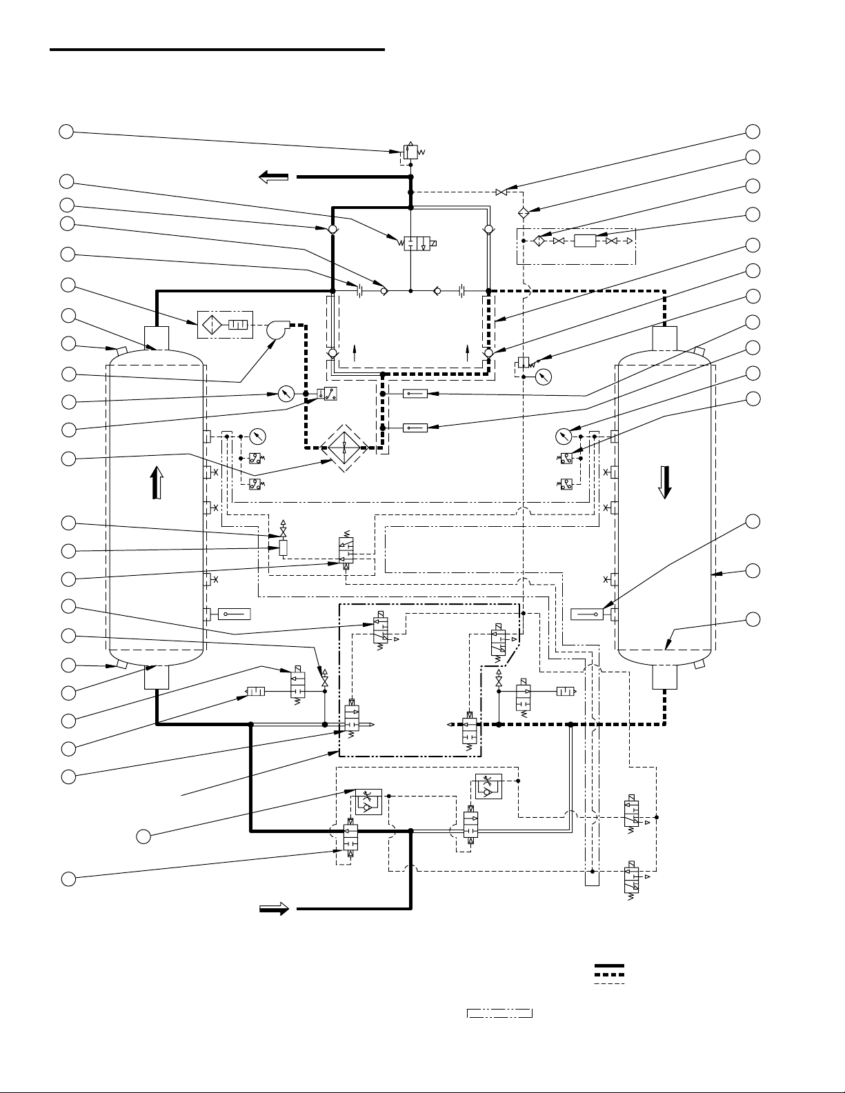
P&ID Schematic
10
WET GAS
INLET
2
1
17
5
19
21
29
19
16
42
43
13
30
6
23
24
20
DRY GAS
OUTLET
25
28
27
4
54
V2
SOL 'D'
1A
V1
SOL 'F'
EXH.
V9
RTD
1
V3
V4
SOL 'B
'
SOL 'A
'
EXH.
SOL 'G
'
V1
0
RTD
2
1PS
(RTD4/HS1)
ENERGY MGMT OPTION
SET @ 176°F
DRYING
EXH.
3PS
SET
@
5 PSIG
SOL 'C'
2
1
3
LEFT
TOWER
SET
@
45 PSI
G
M
1T
S
(225°F)
RTD
3
SET @ 650°F
1TC
SET @ 370°F
V5
V6
2PS
REGE
N
SET @ 176°F
4PS
SET
@
5 PSIG
18
9
RIGH
T
TOWER
SET
@
45 PSIG
SET AT
100 PSIG
12
11
8
7
26
V12 V13
SOL 'E'
V11V7
V8
SET @ 165 PSI
G
DEWPOINTER OPTION
DPA
15
3
22
14
13
44A
MODEL 750 ONLY
(SEE DETAIL 'A
'
FOR 900-4300)
SOLENOID VA
LVES 'B', 'D', & 'G' ARE SHOWN ENERGIZED,
SYMBOLS ARE PER ANSI Y32.10 "GRAPHIC SYMBOLS FOR FLUID POWER DIAGRAMS."
SOLENOID VA
LVES 'A', 'C', 'E', & 'F' ARE SHOWN DE-ENERGIZED.
AS SHOWN FLOW DIRECTION IS:
INDICATES OPTION
3.
2.
1.
PILOT GAS LINE
RIGHT CHAMBER REGEN
LEFT CHAMBER DRYING
NOTES
4.
44
OPEN 5 TURNS
FROM FULL CLOSED
AND LOCK IN PLAC
E
Models 750 through 4300 (Contact factory to request certified drawings)
36

LEGEND
*
= FAILS IN POSITION
LEFT CHAMBER DRYING (RIGHT CHAMBER REGEN)
CLOSEDNO
3 WAY
3 WA
Y
SOLENOID
VALVE 'D'
SOLENOID
VALV
E 'C'
N.O.
VALV
E 'E'
SOLENOID
3 WA
Y
HEATER
OPEN
CLOSED
OPEN
CLOSED
NO
YES
NO
V4
YES
V3
CLOSED
OPEN
ON
OFF
YES
NO
YES
NO
FIXED CYCLE TIMING
(T
IME IN MINUTES)
ENER
G
IZED
PROCESS
CO
MPONENT
ELECTRICAL CO
MPONEN
T
3 WAY
SOLENOID
VALVE 'A'
SOLENOID
VALV
E 'B'
ST
ATUS
PROCESS
CO
MPONENT
DEPRESSURIZ
A
TION
HE
ATIN
G
OPEN
CLOSED
OPEN
YES
NO
YES
V1
V2
257178
*
*
*
*
RIGHT CHAMBER DRYING (LEFT CHAMBER REGEN)
HE
ATIN
G
HOL
D
2ND ST
AG
E REGENE
R
A
TIO
N
REPRESSURI
ZA
TI
ON
DEPRESSURIZ
A
TION
3 1782
HOL
D
LO
SS OF POWER
REPRESSURI
ZA
TION
3
57
VALVE 'F'
V9
SOLENOID
VALV
E 'G'
N.C.
N.C.
NO
YES
NO
OPEN
CLOSED
CLOSED
V10
SOLENOID
YES OPEN
MOTOR
OFF
ON
NO
YES
V11
BLOWER
(JUMPER SE
L
ECTABLE)
2ND ST
AGE RE
GENE
R
AT
IO
N
(JUMPER
SELECT
ABL
E)
DETAIL 'A' (MODELS 900-4300)
V4
SOL 'C'
V3
2
3
4
1
5
2
3
SOL 'D'
4
1
5
1. INLET VALVE (V1 LEFT, V2 RIGHT)
1A. FLOW CONTROL VALVE
2. PURGE EXHAUST VALVE (V3 LEFT, V4 RIGHT)
3. PURGE CHECK VALVE (V5 LEFT, V6 RIGHT) (NO SPRING)
4. OUTLET CHECK VALVE (V7 LEFT, V8 RIGHT)
5. DEPRESS SOLENOID VALVE (V9 LEFT, V10 RIGHT)
6. PURGE HEATER WITH INSULATION
7. HEATER TEMPERATURE THERMOCOUPLE
8. HEATER OVERTEMPERATURE RTD
9. CHAMBER RTD (LEFT & RIGHT)
10. RELIEF VALVE
11. CHAMBER PRESSURE GAUGES (LEFT & RIGHT)
12. CHAMBER PRESSURE SWITCH (LEFT & RIGHT)
13. SERVICE VALVE
14. PILOT AIR FILTER
15. PRESSURE REGULATOR & GAUGE
16. SOLENOID VALVE
17. MUFFLER
18. DESICCANT CHAMBER
19. DESICCANT RETAINING SCREEN (TOP & BOTTOM)
20. DESICCANT FILL PORT
21. DESICCANT DRAIN PORT
22. HOT PIPE INSULATION
23. PURGE PRESSURE GAUGE
24. PURGE BLOWER AND MOTOR
25. PURGE SUCTION FILTER SILENCER
26. REPRESS/SWEEP SOLENOID VALVE (V11)
27. REPRESS/SWEEP CHECK VALVE (V12 LEFT, V13 RIGHT)
28. REPRESS/SWEEP ORIFICE
29. CHAMBER BLOW-DOWN VALVE
30. TEMPERATURE SWITCH (MODELS 3200 - 4300 ONLY)
ENERGY MANAGEMENT OPTION
42. ENERGY MANAGEMENT PILOT OPERATED VALVE
43. ENERGY MANAGEMENT SENSOR (RTD4/HS1)
DEWPOINTER OPTION
44. DEWPOINT ANALYZER
44A. DEWPOINT ANALYZER FILTER
INSULATION OPTION
54. CHAMBER INSULATION
Sequence of Operation
(Model 750 through 4300)
37

Electrical Schematic – 460VAC, 3 phase
LOCATED
EXTERNALLY
HEATER OVERTEMPERATURE
RPS
RPS
IN2
RT
D5-
IN1
LPS
LPS
RT
D3-
RT
D3+
RT
D5+
RT
D4-
RT
D4+
RTD1
RT
D
RTD
RIGHT CHAMBER
LEFT CHAMBER
RT
D
RTD3
RTD2
ANLG2+
ANLG2-
RT
D2-
RTD2+
+5VDC
DC COM
RT
D1-
RT
D1+
ANLG1-
ANLG1+
+12VDC
DC COM
PE
PE
N
L
L
N
SET @ 45 PSIG2PS
PRESSURE SWITCH
RIGHT CHAMBER
SET @ 45 PSIG1PS
PRESSURE SWITCH
LEFT CHAMBER
SENSOR
5VDC
1-5VDC OUT
+
DEWPOINT
TRANSMITTER
1TC
+ -
L1
N
K TYPE
HC
L DRY
ALARM
OUT2
CONTACTS
NO
C
NC
R DRY
OUT1
R DRY
L
DRY
SOLENOID "B"
SOLENOID "A"
L
PURGE
L
PURGE
R PURGE
R PURGE
IN3
2CR
3CR
LOW TENSION
ENCLOSURE
HIGH TENSION
ENCLOSURE
CUSTOMER PROVIDED
460VAC, 3 PHASE
(FOR FUSING AND WIRE
407
40
8
101A
460V
AC
115V
AC
2CR1
3CR1
SOLENOID "F
"
SOLENOID "G
"
1T
2FU
1FU
3FU
L2
L1
L4
L5
L6
HC1
HC2
HC3
404
405
406
+ 4-20MA OUT
ENERGY MGMT
OPTION
RT
D4
+
-
1HTR
102
101
102
102
102
1CR
102
101
101
101
109
111
101
107
SOLENOID "C"
21
LEFT CHAMBER PURGE
EXHAUST
HEAT ENABLE
C NO
101
102
20
21
80
81
70
72
21
10
11
84
85
86
87
88
89
32
33
34
35
50
51
52
53
54
55
56
57
59
20
20
21
TO
TB3
+12VDC
FROM TB6
SOLENOID "E
"
+12VDC
20 21
+
-
-
+
-
+
-
+
4CR
1CR1
104
105
102
+ -
+ -
+ -
+ -
3
G
1
RED
ORANGE
GREEN
BROWN
BLACK
249 OHM
1/8W
EXTERNALLY
LOCATED
OPTION
102
120VAC
TO
TB3
101
102
101
120VAC
FROM TB5
101
11
5
21
109
3PS
110
CLOSES @ 5 PSIG
4CR1
104
101
5CR1
MC-AUX
LEFT CHAMBER DEPRESS
111
4PS
SOLENOID "D
"
21
102
102
11
2
5CR
RIGHT CHAMBER DEPRESS
EXHAUST
RIGHT CHAMBER PURG
E
L3
L2
L1
MC1
MC3
MC2
403
402
401
MOTOR
1M
{
SIZING SEE TABLE 1)
106
20
4CR2
23
20
5CR2
24
~
~
+12VDC
FROM TB6-1 FROM TB6-
2
DC COM
OL-AUX
36
37
H1 H3
X1 X2
OL1
OL2
OL3
H2 H4
21
GREEN
BLACK
RED
SET @ 225°F
1TS
3200, 3600 & 4300
USED ON MODEL
S
38
39
0.5 AM
P
0.5 AM
P
1.25 AMP
TB5
CLOSES @ 5 PSIG
1TR (OFF-DELAY, SET @ 180S)
108
102
15 18
1TR1
A1B1A2
MC
102
102
105
101
OL-AUX
104
11
4
101
NOTE
:
SET 1TR ON MODE "D".
(SIGNAL OFF-DELAY)
G
YELLOW
(Contact factory to request certified drawings)
38

Electrical Schematic – 575VAC, 3 phase
LOCATED
EXTERNALLY
HEATER OVERTEMPERATURE
TB1-12
TB1-11
TB1-13
TB2-1
TB1-16
TB1-15
TB1-14
TB2-2
TB2-6
TB2-5
TB2-4
TB2-7
TB2-8
TB2-3
RPS
RPS
IN2
RTD5
-
IN1
LPS
LPS
RTD3
-
RTD3
+
RTD5
+
RTD4
-
RTD4
+
RT
D1
RT
D
RT
D
RIGHT CHAMBER
LEFT CHAMBER
RT
D
RT
D3
RT
D2
TB5-1
TB5-1
TB5-3
TB5-3
TB5-2
TB5-2
TB6-2
TB1-1
TB1-2
TB1-7
TB1-6
TB1-5
TB1-4
TB1-8
TB1-3
TB6-1
TB1-10
TB1-9
ANLG2+
ANLG2-
RTD2
-
RTD2
+
+5VDC
DC COM
RTD1
-
RTD1
+
ANLG1-
ANLG1+
+12VDC
DC COM
PE
PE
N
L
L
N
SET @ 45 PSIG2PS
PRESSURE SWITCH
RIGHT CHAMBER
SET @ 45 PSIG1PS
PRESSURE SWITCH
LEFT CHAMBER
SENSOR
5VDC
1-5VDC OUT
+
DEWPOINT
TRANSMITTER
1TC
+ -
L1
N
K TYPE
1HC
TB3-5L DRY
TB3-6
TB3-8
TB3-7
TB3-11
TB3-10
TB3-9
TB3-12
TB4-1
TB4-3
TB4-2
ALARM
OUT2
CONTACTS
NO
C
NC
R DRY
OUT1
R DRY
L
DRY
SOLENOID "B"
SOLENOID "A"
TB2-10
TB3-1
TB2-9
TB3-3
TB3-2
TB3-4
L
PURGE
L
PURGE
R PURGE
R PURGE
IN3
2CR
3CR
LOW TENSION
ENCLOSURE
HIGH TENSION
ENCLOSURE
510
51
1
101A
575V
AC
115V
AC
2CR1
3CR1
SOLENOID "F
"
SOLENOID "G
"
1T
2FU
1FU
3FU
L2
L1
L7
L8
L9
2HC1
2HC2
2HC3
507
508
509
+ 4-20MA OUT
ENERGY MGMT
OPTION
RT
D4
+
-
2HTR
102
101
102
102
102
1CR
102
101
101
101
109
11
1
101
107
SOLENOID "C
"
21
LEFT CHAMBER DEPRESS
LEFT CHAMBER PURGE
EXHAUST
HEAT ENABLE
C NO
101
102
20
21
80
81
70
72
21
10
11
84
85
86
87
88
89
32
33
34
35
50
51
52
53
54
55
56
57
59
20
20
21
TO
TB3
+12VDC
FROM TB6
SOLENOID "E"
+12VDC
20 21
+
-
-
+
-
+
-
+
4CR
1CR1
104
105
102
+ -
+ -
+ -
+ -
3
G
1
RED
ORANGE
GREEN
BROWN
BLACK
249 OHM
1/8W
EXTERNALLY
LOCATED
OPTION
102
120VAC
TO
TB3
101
102
101
120VAC
FROM TB5
101
11
0
21
109
3PS
11
0
CLOSES @ 5 PSI
G
4CR1
104
101
5CR1
MC-AUX
LEFT CHAMBER DEPRESS
CLOSES @ 5 PSI
G
111
4PS
SOLENOID "D
"
21
102
102
11
2
5CR
RIGHT CHAMBER DEPRESS
EXHAUST
RIGHT CHAMBER PURGE
RIGHT CHAMBER DEPRESS
L6
L5
L4
106
20
4CR2
23
20
5CR2
24
~ ~
+12VDC
FROM TB6-1 FROM TB6-2
DC COM
OL-AUX
36
37
H1
X1 X3
H5
21
GREEN
BLACK
RED
SET @ 225°F
1TS
3200, 3600 & 4300
USED ON MODELS
OL
2
{
MC2
(FOR FUSING AND WIRE
L3
SIZING SEE TABLE 1)
MC3 OL
3
503
L2
575VAC, 3 PHASE
CUSTOMER PROVIDED
L1
MC1 OL
1
501
502
MOTOR
1M
1HC1
1HC3
1HC2
506
505
504
1HTR
2HC
102
3200, 3600 & 4300
USED ON MODEL
S
3200, 3600 & 4300
USED ON MODEL
S
38
39
101
11
4
101
OL-AUX
105
B1
1TR1
108
15 18
A1 A2
102
102
MC
102
(SIGNAL OFF-DELAY
)
SET 1TR ON MODE "D".
NOTE:
1TR (OFF-DELAY, SET @ 180S
)
0.5 AM
P
0.5 AM
P
1.25 AM
P
YELLOW
G
(Contact factory to request certified drawings)
39

Electrical Schematic – 380VAC, 3 phase
LOCATED
EXTERNALLY
HEATER OVERTEMPERATURE
RPS
RPS
IN2
RT
D5-
IN1
LPS
LPS
RT
D3-
RT
D3+
RTD5+
RT
D4-
RT
D4+
RT
D1
RT
D
RTD
RIGHT CHAMBER
LEFT CHAMBER
RTD
RT
D3
RT
D2
ANLG2+
ANLG2-
RT
D2-
RT
D2+
+5VDC
DC COM
RT
D1-
RT
D1+
ANLG1-
ANLG1+
+12VDC
DC COM
PE
PE
N
L
L
N
SET @ 45 PSIG2PS
PRESSURE SWITCH
RIGHT CHAMBER
SET @ 45 PSIG1PS
PRESSURE SWITCH
LEFT CHAMBER
SENSOR
5VDC
1-5VDC OUT
+
DEWPOINT
TRANSMITTER
1TC
+ -
L1 N
K TYPE
HC
L
DRY
ALARM
OUT2
CONTACTS
NO
C
NC
R DRY
OUT1
R DRY
L
DRY
SOLENOID "B
"
SOLENOID "A"
L
PURGE
L
PURGE
R PURGE
R PURGE
IN3
2CR
3CR
LOW TENSION
ENCLOSURE
HIGH TENSION
ENCLOSURE
CUSTOMER PROVIDED
380VAC, 3 PHASE
(FOR FUSING AND WIRE
307
30
8
101A
380VAC
110V
AC
2CR1
3CR1
SOLENOID "F
"
SOLENOID "G
"
1T
2FU
1FU
3FU
L2
L1
L4
L5
L6
HC1
HC2
HC3
304
305
306
+ 4-20MA OUT
ENERGY MGMT
OPTION
RT
D4
+
-
1HTR
102
101
102
102
102
1CR
102
101
101
101
109
111
101 107
SOLENOID "C"
21
LEFT CHAMBER DEPRESS
LEFT CHAMBER PURGE
EXHAUST
HEAT ENABLE
C NO
101
102
20
21
80
81
70
72
21
10
11
84
85
86
87
88
89
32
33
34
35
50
51
52
53
54
55
56
57
59
20
20
21
TO
TB3
+12VDC
FROM TB6
SOLENOID "E"
+12VDC
20 21
+
-
-
+
-
+
-
+
4CR
1CR1
104
105
102
+ -
+ -
+ -
+ -
3
G
1
RED
ORANGE
GREEN
ORANGE
BLACK
249 OHM
1/8W
EXTERNALLY
LOCATED
OPTION
102
120VAC
TO
TB3
101
102
101
120VAC
FROM TB5
101
11
5
21
109
3PS
110
CLOSES @ 5 PSIG
4CR1
104
101
5CR1
MC-AUX
LEFT CHAMBER DEPRESS
CLOSES @ 5 PSIG
111
4PS
SOLENOID "D
"
21
102
102
11
2
5CR
RIGHT CHAMBER DEPRES
S
EXHAUST
RIGHT CHAMBER PURG
E
RIGHT CHAMBER DEPRES
S
L3
L2
L1
MC1
MC3
MC2
303
302
301
MOTOR
1M
{
SIZING SEE TABLE 1)
106
20
4CR2
23
20
5CR2
24
~
~
+12VDC
FROM TB6-1 FROM TB6-2
DC COM
OL-AUX
36
37
H1 H3
X1 X4
OL1
OL
2
OL
3
BLACK
GREEN
RED
21
1TS
USED ON MODELS
3200, 3600 & 4300
SET @ 225°F
39
38
(.5AMP
)
(.5 AMP
)
(1.25 AMP
)
TB5
104
101
1TR (OFF-DELAY, SET @ 180S
)
OL-AUX
114
1815
1TR1
MC
108
105
101
A1B1A2
102
102
NOTE
:
(SIGNAL OFF-DELAY)
SET 1TR ON MODE "D".
102
YELLOW
G
(Contact factory to request certified drawings)
40

Electrical Schematic – 415VAC, 3 phase
LOCATED
EXTERNALLY
HEATER OVERTEMPERATURE
RPS
RPS
IN2
RT
D5-
IN1
LPS
LPS
RT
D3-
RT
D3+
RT
D5+
RT
D4-
RT
D4+
RT
D1
RT
D
RTD
RIGHT CHAMBER
LEFT CHAMBER
RTD
RT
D3
RT
D2
ANLG2+
ANLG2-
RT
D2-
RT
D2+
+5VDC
DC COM
RT
D1-
RT
D1+
ANLG1-
ANLG1+
+12VDC
DC COM
PE
PE
N
L
L
N
SET @ 45 PSIG2PS
PRESSURE SWITCH
RIGHT CHAMBER
SET @ 45 PSIG1PS
PRESSURE SWITCH
LEFT CHAMBER
SENSOR
5VDC
1-5VDC OUT
+
DEWPOINT
TRANSMITTER
1TC
+ -
L1
N
K TYPE
HC
L
DRY
ALARM
OUT2
CONTACTS
NO
C
NC
R DRY
OUT1
R DRY
L
DRY
SOLENOID "B"
SOLENOID "A"
L
PURGE
L PURGE
R PURGE
R PURGE
IN3
2CR
3CR
LOW TENSION
ENCLOSURE
HIGH TENSION
ENCLOSURE
CUSTOMER PROVIDED
415VAC, 3 PHASE
(FOR FUSING AND WIRE
407
40
8
101A
415VAC
120V
AC
2CR1
3CR1
SOLENOID "F
"
SOLENOID "G
"
1T
2FU
1FU
3FU
L2
L1
L4
L5
L6
HC1
HC2
HC3
404
405
406
+ 4-20MA OUT
ENERGY MGMT
OPTION
RT
D4
+
-
1HTR
102
101
102
102
102
1CR
102
101
101
101
109
111
101 107
SOLENOID "C"
21
LEFT CHAMBER DEPRESS
LEFT CHAMBER PURGE
EXHAUST
HEAT ENABLE
C NO
101
102
20
21
80
81
70
72
21
10
11
84
85
86
87
88
89
32
33
34
35
50
51
52
53
54
55
56
57
59
20
20
21
TO
TB3
+12VDC
FROM TB6
SOLENOID "E"
+12VDC
20 21
+
-
-
+
-
+
-
+
4CR
1CR1
104
105
102
+ -
+ -
+ -
+ -
3
G
1
RED
ORANGE
GREEN
ORANGE
BLACK
249 OHM
1/8W
EXTERNALLY
LOCATED
OPTION
102
120VAC
TO
TB3
101
102
101
120VAC
FROM TB5
101
11
5
21
109
3PS
110
CLOSES @ 5 PSIG
4CR1
104
101
5CR1
MC-AUX
LEFT CHAMBER DEPRESS
CLOSES @ 5 PSIG
111
4PS
SOLENOID "D
"
21
102
102
11
2
5CR
RIGHT CHAMBER DEPRESS
EXHAUST
RIGHT CHAMBER PURG
E
RIGHT CHAMBER DEPRES
S
L3
L2
L1
MC1
MC3
MC2
403
402
401
MOTOR
1M
{
SIZING SEE TABLE 1)
106
20
4CR2
23
20
5CR2
24
~
~
+12VDC
FROM TB6-1 FROM TB6-2
DC COM
OL-AUX
36
37
H1 H3
X2 X4
OL1
OL2
OL3
BLACK
GREEN
RED
21
1TS
USED ON MODELS
3200, 3600 & 4300
SET @ 225°F
39
38
0.5 AM
P
0.5 AM
P
1.25 AMP
TB5
HEATER & MOTOR
FUSES BY
CUSTOMER
101
11
4
101
OL-AUX
105
B1
1TR1
108
15 18
A1 A2
102
102
MC
102
(SIGNAL OFF-DELAY)
SET 1TR ON MODE "D".
NOTE
:
1TR (OFF-DELAY, SET @ 180S
)
YELLOW
G
(Contact factory to request certified drawings)
41

Electrical Data – Fusing & Wire Sizing
Electrical Service: 460VAC, 3 phase
MODEL COMPONENT RATING
HEATER 10 KW 12.6 20 AMPS #12 AWG
500
600
750
900
1050
1300
1500
1800
2200
2600
3200
3600
4300
MOTOR 2.5 HP 4.1 7.5 AMPS #12 AWG
HEATER 12 KW 15.1 20 AMPS #12 AWG
MOTOR 4 HP 6.2 10 AMPS #12 AWG
HEATER 14 KW 17.6 25 AMPS #12 AWG
MOTOR 4 HP 6.2 10 AMPS #12 AWG
HEATER 17 KW 21.3 30 AMPS #10 AWG
MOTOR 4 HP 6.2 10 AMPS #12 AWG
HEATER 19 KW 23.8 30 AMPS #10 AWG
MOTOR 5 HP 7.6 12 AMPS #12 AWG
HEATER 23 KW 28.9 40 AMPS #8 AWG
MOTOR 7.5 HP 11 17.5 AMPS #12 AWG
HEATER 28 KW 35.1 45 AMPS #8 AWG
MOTOR 10 HP 14 20 AMPS #12 AWG
HEATER 33 KW 41.4 60 AMPS #6 AWG
MOTOR 10 HP 14 20 AMPS #12 AWG
HEATER 40 KW 50.2 70 AMPS #4 AWG
MOTOR 10 HP 14 20 AMPS #12 AWG
HEATER 45 KW 56.5 80 AMPS #4 AWG
MOTOR 15 HP 21 30 AMPS #10 AWG
HEATER 54 KW 67.8 90 AMPS #2 AWG
MOTOR 5 HP 7.6 12 AMPS #12 AWG
HEATER 60 KW 75.3 100 AMPS #2 AWG
MOTOR 5 HP 7.6 12 AMPS #12 AWG
HEATER 70 KW 87.9 110 AMPS #2 AWG
MOTOR 7.5 HP 11 17.5 AMPS #12 AWG
F.L.A.
@460VAC
SUGGESTED
FUSING
WIRE SIZE
Electrical Service: 575VAC, 3 phase
MODEL COMPONENT RATING
HEATER 10 KW 10.0 15 AMPS #12 AWG
500
600
750
900
1050
1300
1500
1800
2200
2600
3200*
3600*
4300*
MOTOR 2.5 HP 3.3 6 AMPS #12 AWG
HEATER 12 KW 12.0 20 AMPS #12 AWG
MOTOR 4 HP 5 9 AMPS #12 AWG
HEATER 14 KW 14.1 20 AMPS #12 AWG
MOTOR 4 HP 5 9 AMPS #12 AWG
HEATER 17 KW 17.1 25 AMPS #12 AWG
MOTOR 4 HP 5 9 AMPS #12 AWG
HEATER 19 KW 19.1 25 AMPS #12 AWG
MOTOR 5 HP 6.1 9 AMPS #12 AWG
HEATER 23 KW 23.1 30 AMPS #8 AWG
MOTOR 7.5 HP 9 15 AMPS #12 AWG
HEATER 28 KW 28.1 40 AMPS #8 AWG
MOTOR 10 HP 11 17.5 AMPS #12 AWG
HEATER 33 KW 33.1 50 AMPS #8 AWG
MOTOR 10 HP 11 17.5 AMPS #12 AWG
HEATER 40 KW 40.2 60 AMPS #6 AWG
MOTOR 10 HP 11 17.5 AMPS #12 AWG
HEATER 45 KW 45.2 60 AMPS #6 AWG
MOTOR 15 HP 17 25 AMPS #10 AWG
HEATER 2 – 27 KW 2 – 27.1 2 – 40 AMPS 2 – #8 AWG
MOTOR 5 HP 6.1 9 AMPS #12 AWG
HEATER 2 – 30 KW 2 – 31.1 2 – 40 AMPS 2 – #8 AWG
MOTOR 5 HP 6.1 9 AMPS #12 AWG
HEATER 2 – 35 KW 2 – 35.1 2 – 40 AMPS 2 – #8 AWG
MOTOR 7.5 HP 9 15 AMPS #12 AWG
F.L.A.
@575VAC
* Models 3200, 3600 and 4300 use a two-stage heater circuit with two contactors,
six fuses, and six wires.
SUGGESTED
FUSING
WIRE SIZE
Electrical Service: 380VAC, 3 phase
MODEL COMPONENT RATING
HEATER 10 KW 15.2 25 AMPS #12 AWG
500
600
750
900
1050
1300
1500
1800
2200
2600
3200
3600
4300
MOTOR 3 HP 6 12 AMPS #12 AWG
HEATER 12 KW 18.2 25 AMPS #12 AWG
MOTOR 5 HP 9 17.5 AMPS #12 AWG
HEATER 14 KW 21.3 30 AMPS #10 AWG
MOTOR 3 HP 6 12 AMPS #12 AWG
HEATER 17 KW 25.8 35 AMPS #10 AWG
MOTOR 3 HP 6 12 AMPS #12 AWG
HEATER 19 KW 28.9 40 AMPS #8 AWG
MOTOR 5 HP 9 17.5 AMPS #12 AWG
HEATER 23 KW 34.9 45 AMPS #8 AWG
MOTOR 7.5 HP 13 20 AMPS #12 AWG
HEATER 28 KW 42.5 55 AMPS #6 AWG
MOTOR 10 HP 16 30 AMPS #10 AWG
HEATER 33 KW 50.1 65 AMPS #6 AWG
MOTOR 12.5 HP 23.7 40 AMPS #10 AWG
HEATER 40 KW 60.8 80 AMPS #4 AWG
MOTOR 7.5 HP 13 20 AMPS #12 AWG
HEATER 45 KW 68.4 90 AMPS #2 AWG
MOTOR 15 HP 24 40 AMPS #12 AWG
HEATER 54 KW 82.0 100 AMPS #2 AWG
MOTOR 7.5 HP 13 20 AMPS #12 AWG
HEATER 58 KW 88.1 110 AMPS #2 AWG
MOTOR 7.5 HP 13 20 AMPS #12 AWG
HEATER 70 KW 106.4 150 AMPS #1/0 AWG
MOTOR 7.5 HP 13 20 AMPS #12 AWG
F.L.A.
@380VAC
SUGGESTED
FUSING
WIRE SIZE
Electrical Service: 415VAC, 3 phase
MODEL COMPONENT RATING
HEATER 10 KW 13.9 20 AMPS #12 AWG
500
600
750
900
1050
1300
1500
1800
2200
2600
3200
3600
4300
MOTOR 3 HP 6 10 AMPS #12 AWG
HEATER 12 KW 16.7 25 AMPS #10 AWG
MOTOR 5 HP 8 15 AMPS #12 AWG
HEATER 14 KW 19.5 25 AMPS #10 AWG
MOTOR 3 HP 6 10 AMPS #12 AWG
HEATER 17 KW 23.7 30 AMPS #10 AWG
MOTOR 4.2 HP 5.6 15 AMPS #12 AWG
HEATER 19 KW 26.4 40 AMPS #8 AWG
MOTOR 5 HP 8 15 AMPS #12 AWG
HEATER 23 KW 32.0 40 AMPS #8 AWG
MOTOR 7.5 HP 12 20 AMPS #12 AWG
HEATER 28 KW 39.0 50 AMPS #8 AWG
MOTOR 10 HP 15 25 AMPS #10 AWG
HEATER 33 KW 45.9 60 AMPS #6 AWG
MOTOR 12.5 HP 17 30 AMPS #10 AWG
HEATER 40 KW 55.6 70 AMPS #4 AWG
MOTOR 7.5 HP 12 20 AMPS #12 AWG
HEATER 45 KW 62.6 80 AMPS #4 AWG
MOTOR 15 HP 22 40 AMPS #8 AWG
HEATER 53 KW 73.7 100 AMPS #2 AWG
MOTOR 5 HP 8 15 AMPS #12 AWG
HEATER 58 KW 80.7 110 AMPS #2 AWG
MOTOR 7.5 HP 12 20 AMPS #12 AWG
HEATER 70 KW 97.4 125 AMPS #1 AWG
MOTOR 7.5 HP 12 20 AMPS #12 AWG
F.L.A.
@415VAC
SUGGESTED
FUSING
WIRE SIZE
42

43

WARRANTY
SPX Dehydration & Filtration
1000 Philadelphia Street
Canonsburg, PA 15317-1700 U.S.A.
Phone: 724-745-1555 • Fax: 724-745-6040
Email: hankison.service@dehydration.spx.com
www.hankisonintl.com
© 2008 SPX Dehydration & Filtration. All rights reserved.
The manufacturer warrants the product manufactured by it, when properly installed, operated, applied, and maintained in accordance with the procedures and recommendations outlined in the manufacturer’s instruction manuals, to be free from defects in material
or workmanship for a period of one (1) year from the date of shipment from the manufacturer or the manufacturer’s authorized distributor,
or eighteen months from the date of shipment from the factory, whichever occurs first, provided such defect is discovered and brought to
the manufacturer’s attention the aforesaid warranty period. The manufacturer will repair or replace any product or part determined to be
defective by the manufacturer within the warranty period, provided such defect occurred in normal service and not as the result of misuse,
abuse, neglect, or accident.
The warranty covers parts and labor for the warranty period. Repair or replacement shall be made at the factory or the installation site,
at the sole option of the manufacturer. The manufacturer must first authorize any service performed on the product by anyone other than
the manufacturer. Normal maintenance items requiring routine replacement are not warranted. Unauthorized service voids the warranty
and any resulting charge or subsequent claim will not be paid.
THE FOREGOING WARRANTY IS EXCLUSIVE AND IN LIEU OF ALL OTHER WARRANTIES, WRITTEN, ORAL, OR STATUTORY,
AND IS EXPRESSED IN LIEU OF THE IMPLIED WARRANTY OF MERCHANTABILITY AND THE IMPLIED WARRANTY OF FITNESS
FOR A PARTICULAR PURPOSE. THE MANUFACTURER SHALL NOT BE LIABLE FOR LOSS OR DAMAGE BY REASON OF STRICT
LIABILITY IN TORT OR ITS NEGLIGENCE IN WHATEVER MANNER INCLUDING DESIGN, MANUFACTURE, OR INSPECTION OF
THE EQUIPMENT OR ITS FAILURE TO DISCOVER, REPORT, REPAIR, OR MODIFY LATENT DEFECTS INHERENT THEREIN. THE
MANUFACTURER, HIS REPRESENTATIVE OR DISTRIBUTOR SHALL NOT BE LIABLE FOR LOSS OF USE OF THE PRODUCT OR
OTHER INCIDENTAL OR CONSEQUENTIAL COSTS, EXPENSES, OR DAMAGES INCURRED BY THE BUYER, WHETHER ARISING
FROM BREACH OF WARRANTY, NEGLIGENCE OR STRICT LIABILITY IN TORT.
The manufacturer does not warranty any product, part, material, component, or accessory manufactured by others and sold or supplied in connection with the sale of the manufacturer’s products.
AUTHORIZATION FROM THE SERVICE DEPARTMENT IS NECESSARY BEFORE
MATERIAL IS RETURNED TO THE FACTORY OR IN-WARRANTY REPAIRS ARE MADE.
SERVICE DEPARTMENT : (724) 746-1100
 Loading...