

HANKISON Filter Monitor Instruction Manual

7610.718.14 4/02
INSTRUCTION MANUAL
Introduction
The Filter Monitor continuously monitors the differential
pressure (pressure drop) across a filter and alerts the
operator of the need for element replacement when
any of three operating criteria are met:
1. Maximum elapsed time (service interval) before
change-out - operator alerted when user selected
time period elapses.
2. Maximum allowable differential pressure - operator
alerted when user selected maximum differential
pressure occurs.
3. Intelligence - operator alerted when the optimum time
to replace the element(s) has occurred. The Monitor
calculates this using the element type, the initial characteristic pressure drop and historical pressure drop data.
Recommended Settings for HF Series Filters
1. Maximum time before element replacement: Grades 9, 7, 6, 5, 3, - 12 MONTHS;
Grades 1 - 6 MONTHS;
2. Maximum pressure differential:
HF Series Setting Element
Grade psid kgf/cm
Grade 9 3 0.21 0.20 B
Grade 7 4 0.28 0.28 C
Grade 6 4 0.28 0.28 D
Grade 5 5 0.35 0.34 E
Grade 3 6 0.42 0.41 F
Grade 1 3 0.21 0.20 G
Programming Instructions
(Short version - for complete instructions see page 3)
1. To begin programming, press and hold ENTER button
for 3 seconds.
2. Press and hold the scroll button to input maximum
service interval (1 to 15 months) - press ENTER.
3. Press and hold the scroll button to select pressure unit
of measure (KG/CM
4. Press and hold the scroll button to input maximum
pressure drop (0.01 to 1.00 KG/CM
15 PSI) Use Left Shift and Right Shift buttons to select
advance rate (e.g. by ones, tenths, or hundredths) press ENTER.
5. Press and hold the scroll button to select the element
letter type (see chart above) - press ENTER.
6. Select Initalize or Run mode.
Initalize - Scroll until initial pressure drop and run icons
are displayed. (To be selected during initial installation
and element charge out).
Run -Scroll until run icon only is displayed. (To be
selected if Monitor is reprogrammed without changing
the element).
7. Press ENTER to start program.
2
,PSI, or BAR). - press ENTER.
SHIFT LEFT
BUTTON
SHIFT RIGHT
BUTTON
2
2
or BAR; 0.1 to
bar Letter Type
FILTER
MONITOR
LIQUID
CRYSTAL
DISPLAY
INITIAL P ICON
SCROLL
BUTTON
ENTER
BUTTON
OPERATOR
ALERT LIGHT
(RED LED)
RUN ICON
SERVICE DEPARTMENT: (724) 746-1100
1
1.0 INSTALLATION
1
2
34
5
67
9
101112131415
16
17
8
1.1 Operating conditions
Maximum operating pressure: 250 psig, 17.6 kgf/cm2,
17.2 bar
Maximum compressed air temperature: 180°F, 82 °C
Minimum/maximum ambient temperature: 10/130°F,
-12/54°C
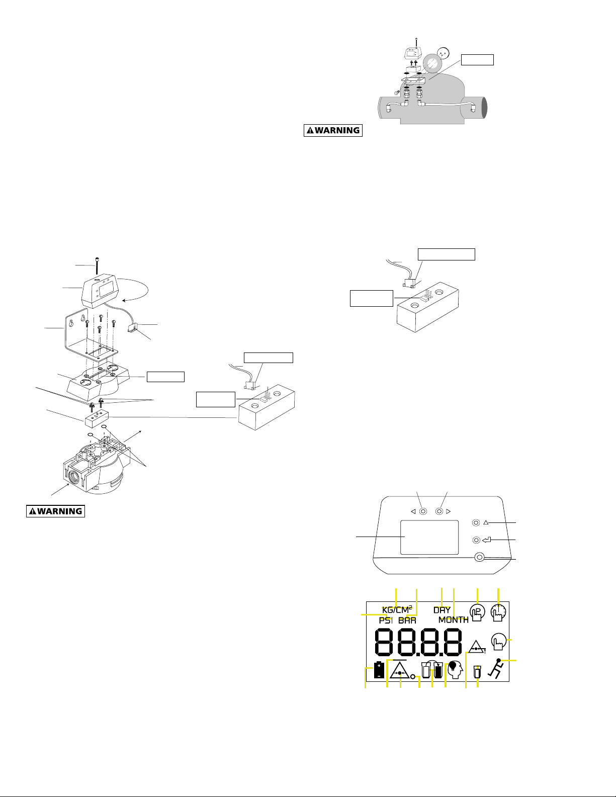
1.2 Mounting
A. Changing orientation on units with Monitor
installed
1. Remove Monitor mounting screw.
2. Lift Monitor and turn 180°.
Note: Make certain that connector to mounting block is
not disconnected.
3. Reinstall Monitor to mounting block with mounting
screw.
B. Retro-fitting bowl/head type housings
MOUNTING SCREW
MONITOR
C. Pressure vessel type housings
MOUNT TO VESSEL
AS SHOWN
OR REMOTELY TO WALL.
IN
OUT
Make certain filter is depressurized before disassembly.
1. If mounting hardware has not been previously
installed, remove inlet/outlet port plugs and install
fittings, tubing, couplings, and brackets using parts
from Mounting Kit.
2. Connect mounting block to couplings using o-rings
and transmission bolts supplied with Monitor.
NOTE: Torque bolts to 30 inch-pounds (3.4 N-m). Do not
over tighten.
MOUNT WITH LEGS FACING
RAISED RECTANGLE
LEAD
LEG
MOUNT WITH
RAISED RECTANGLE
ON INLET SIDE
OPTIONAL
FILTER
BRACKET
GASKETS
MOUNTING
BLOCK
CAP
IN
OUT
O-RINGS
LEAD
LEG
ENLARGE OPENING
IF NECESSARY
TRANSMISSON
BOLTS
MOUNT WITH
RAISED RECTANGLE
ON INLET SIDE
Make certain filter is depressurized before disassembly.
1. Remove existing differential pressure devices or port
plugs if installed.
2. Install mounting block on filter head using o-rings,
gaskets and transmission bolts supplied with Monitor.
NOTE: Torque bolts to 30 inch-pounds (3.4 N-m). Do not
over tighten.
IMPORTANT: Mount block so that raised rectangle is next to
the INLET (high pressure or upstream) side of filter.
Note: Enlarge opening in cap if necessary. A pattern for a
larger cutout is located on underside of cap.
3. Connect lead from Monitor to prongs in mounting
block.
IMPORTANT: Position connector so that legs on connector
are on same side as raised rectangle.
4. Mount Monitor on mounting block using mounting
screw provided.
NOTE: Monitor may be rotated 180° so that it faces forward
with filter flowing from left-to-right or right-to-left.
2
MOUNT WITH LEGS FACING
RAISED RECTANGLE
LEAD
LEG
IMPORTANT: Mount block so that raised rectangle is next to
the INLET (high pressure or upstream side) connection.
3. Connect lead from filter monitor to prongs in
mounting block.
IMPORTANT: Connect so that legs on connector are on same
side as raised rectangle.
4. Mount Monitor on mounting block using mounting
screw provided.
2.0 OPERATION
2.1 Display Legend
SHIFT RIGHT
BUTTON
SCROLL
BUTTON
ENTER
BUTTON
OPERATOR
ALERT LIGHT
(RED LED)
LIQUID
CRYSTAL
DISPLAY
SHIFT LEFT
BUTTON
LED DISPLAY
1. Unit of measure selection - pressure - pounds per
square inch.
2. Unit of measure selection - pressure - kilograms per
square centimeter.
3. Unit of measure selection - pressure - bar.
 Loading...