

Hankinson International DH-25, DH-45, DH-6000, DH-80, DH-115 Instruction Manual
...
7610.479.9 1/22/97
Instruction Manual
DH Series
GENERAL SAFETY
INFORMATION
1. Pressurized devices: This equipment is
a pressure containing device. Do not
exceed maximum operating pressure as
shown on equipment serial number tag.
Make sure equipment is depressurized
before working on or disassembling it
for service.
2. Electrical: This equipment requires
electricity to operate. Install equipment
in compliance with national and local
electrical codes. Standard equipment is
supplied with NEMA 4, 4x electrical
enclosures and is not intended for
installation in hazardous environments.
Disconnect power supply to equipment
when performing any electrical service
work.
3. Breathing Air: Air treated by this
equipment may not be suitable for
breathing without further purification.
Refer to OSHA standard 1910.134 for
the requirements for breathing quality
air.
IMPORTANT:
READ PRIOR TO STARTING THIS
EQUIPMENT
A.
UNPACKING
This shipment has been thoroughly checked,
packed and inspected before leaving our plant.
It was received in good condition by the
carrier and was so acknowledged.
1. Check for Visible Loss or Damage. If this
shipment shows evidence of loss or damage
at time of delivery to you, insist that a notation
of this loss or damage be made on the delivery
receipt by the carrier’s agent.
2. Check for Concealed Loss or Damage. When a
shipment has been delivered to you in
apparent good order, but concealed damage is
found upon unpacking, notify the carrier
immediately and insist on his agent inspecting
the shipment. Fifteen days from receipt of
shipment is the maximum time limit for
requesting such inspection. Concealed
damage claims are not our responsibility as
our terms are F.O.B. point of shipment.
MOVING CAUTION:
B.
Do not lift by piping. Use lifting lugs or fork lift.
®
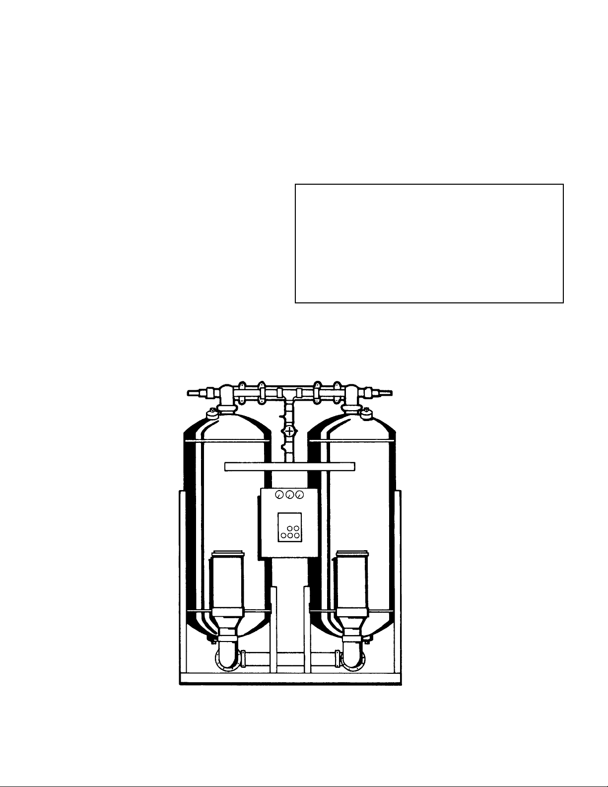
PRESSURE-SWING
DESICCANT TYPE
COMPRESSED
AIR DRYERS
MODEL RATED FLOW DESIGNATED AS MODELS
DH-25 25 SCFM 25
DH-45 45 SCFM 45
DH-6000 60 SCFM 60
DH-80 80 SCFM 80
DH-115 115 SCFM 115
DH-165 165 SCFM 165
DH-260 260 SCFM 260
DH-370 370 SCFM 370
DH-450 450 SCFM 450
DH-590 590 SCFM 590
DH-750 750 SCFM 750
DH-930 930 SCFM 930
DH-1130 1130 SCFM 1130
DH-1350 1350 SCFM 1350
DH-1550 1550 SCFM 1550
DH-2100 2100 SCFM 2100
DH-3000 3000 SCFM 3000
DH-4100 4100 SCFM 4100
DH-5400 5400 SCFM 5400
SERVICE DEPARTMENT (724) 746-1100
1

CONTENTS
1.0 DESCRIPTION ............................................................................................................................ 4
1.1 Function...................................................................................................................................... 4
1.2 Description of Operation.......................................................................................................... 5
2.0 INSTALLATION .......................................................................................................................... 6
2.1 Location in a compressed air system...................................................................................... 6
2.2 Minimum & Maximum Operating Conditions .......................................................................... 6
2.3 Mounting..................................................................................................................................... 6
2.4 Piping.......................................................................................................................................... 6
2.5 Electrical connections..............................................................................................................10
2.6 Provisions for purge exhaust ..................................................................................................10
2.7 Initial Desiccant Charge ...........................................................................................................10
3.0 OPERATION ..............................................................................................................................12
3.1 Start-up ......................................................................................................................................12
3.2 Operational check points.........................................................................................................14
3.3 Shut-down ................................................................................................................................ 15
3.4 Loss of power ...........................................................................................................................15
3.5 Design parameters ..................................................................................................................16
3.6 Determining purge and outlet flows .......................................................................................16
3.7 Outlet dew points vs. inlet temperatures ...............................................................................16
4.0 MAINTENANCE .........................................................................................................................18
4.1 Desiccant replacement.............................................................................................................18
4.2 Pilot air filter cartridge replacement (models 370 & larger only) ........................................18
4.3 Fuse Replacement (automatic purge models only)...............................................................19
4.4 Battery replacement (automatic purge models only)...........................................................19
4.5 Test Mode ..................................................................................................................................19
5.0 TROUBLESHOOTING ...............................................................................................................21
NOTE
Supplemental instructions for units supplied with the
optional Automatic Purge Saving System are shown in italics.
2

MINI INSTRUCTIONS
For complete instructions on installation, operation, and maintenance, consult manual.
I . INSTALLATION
1. Install on level surface.
2. Ambient temperature range: 35 to 120°F (1.7 to 49°C) [ if low ambient package supplied: -10 to 120°F (-23 to 49°C) ]
3. Install purge mufflers if shipped separately.
4. Connect air from compressor to inlet.
• Maximum compressed air temperature: 120°F (49°C)
• Maximum compressed air pressure: Refer to serial number tag.
• Minimum compressed air pressure: See section 2.2.1.2 .
5. Connect outlet to air system.
6. Refer to serial number tag for correct voltage. Make electrical connection to terminal strip in electrical enclosure. Standard units: connect
line to position 5, neutral to position 6 and ground to position 7.
Automatic purge saving system: connect wires to positions 2 and 3; ground to position 1.
7. Set controller for 120V or 240V using selector switch.
I I. START UP
1. Set or verify controller settings. See section 3.1.1.
2. SLOWLY pressurize unit.
3. Energize dryer by turning on/off switch on. ("I" is on; "O" is off)
4. Adjust purge air flow rate. Turn purge rate valve until Purge Pressure Gauge reads as shown in the following table.
NOTE: One tower must be purging when setting purge pressure.
150 psig M.W.P. models
INLET PRESSURE 60-100 110 120 130 140 150
(psig)
CYCLE
TIME
SETTING
10
Min.
4
Min.
45 43 41 39 37 36
70 66 63 60 58 56
250 psig M.W.P. models
INLET PRESSURE 125 130 135 140 145 150 175 200 225 250
(psig)
CYCLE
TIME
SETTING
10
Min.
4
Min.
80 79 78 77 76 75 70 64 60 57
—————132123115108102
III . OPERATIONAL CHECKPOINTS
1. Check that dryer is energized (indicating lights are illuminated)
2. MOISTURE INDICATOR - Indicator should be green (Allow 4 hours after start up for indicator to turn green).
3. TOWER PRESSURE GAUGES -
• Tower on line should read line pressure
• Tower off line should read 2 psig or less while purging. If pressure exceeds 2 psig replace purge muffler elements.
NOTE: An extra set of elements is shipped with dryer.
4. PURGE PRESSURE GAUGE - Verify proper setting.
5. CHECK FOR ALARM CONDITION.
IV . DEPRESSURIZATION
Isolate dryer. Run timer until both tower pressure gauges read 0 psig.
3
1.0 DESCRIPTION
1.1 Function
1.1.1 Dryer Dual tower regenerative desiccant dryers are an economical
and reliable way to dry compressed air to dew points below the freezing
point of water (dew points as low as -150°F [1 ppb @ 100 psig, 7.0 kgf/
2
] are possible) or reduce the moisture content of compressed air when
cm
used in critical process applications.
These dryers continuously dry compressed air by using two identical
towers, each containing a desiccant bed. While one tower is on-stream
drying the compressed air, the other tower is off-stream being regenerated
(reactivated, i.e., dried out). The towers are alternated on- and off-stream
so that dry desiccant is always in contact with the wet compressed air. In
this way a continuous supply of dry air downstream is possible.
Desiccant dryers lower the dew point of compressed air by adsorbing the
water vapor present in the compressed air onto the surface of the
desiccant. Desiccant is a highly porous solid containing extensive surface
area.
Adsorption occurs until the partial pressure of the water vapor in the air
and that on the surface of the desiccant come into equilibrium. As
adsorption occurs, heat is released (referred to as the heat of adsorption)
and is stored in the bed for use during regeneration.
Desiccant is regenerated by driving off (desorbing) the water collected on
its surface. Pressure-swing (also called heatless or heaterless because no
outside heat is added) dryers regenerate by expanding a portion (approximately 14 - 15% at 100 psig, 7 kgf/cm
pressure. This “swing in pressure” causes the expanded air to become
very dry (have a very low vapor pressure). This very dry air (called purge
air) plus the stored heat of adsorption allows the moisture to desorb from
the desiccant. The purge air then carries the desorbed water out of the
dryer.
2
) of the dried air to atmospheric
1.1.2 Optional Automatic Purge Saving System
The Automatic Purge Saving System is designed to save energy (purge
air) when pressure-swing dryers are operated at reduced loads.
The patented Purge Saving System operates by monitoring the changes
in temperature within the desiccant beds. These changes in temperature
are the result of heat (thermal energy) that is released when a bed is online drying (heat of adsorption), and the heat that is used when a bed is
off-line being regenerated (heat of desorption).
The magnitude of these changes in temperature is an indirect measure of
the water vapor content in the air being dried. This information is used to
determine the time a tower stays on line during the drying cycle.
4
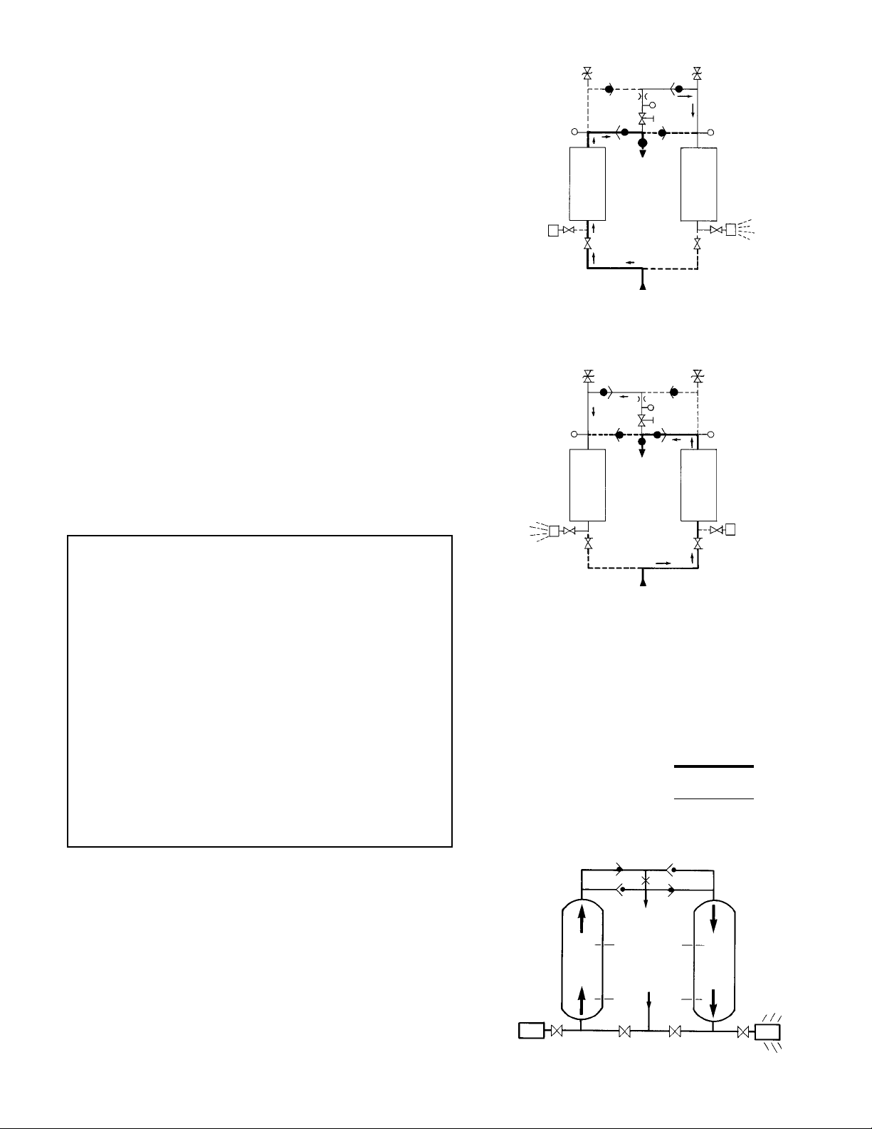
1.2 Description of Operation
1.2.1 Dryer
(4A) where the air is dried. After the air is dried it flows through check
valve (5A) and then to the dryer outlet.
main air stream prior to the outlet. The purge stream flow rate is controlled
by the adjustable purge rate valve (6) and the purge orifice (7).
pressure, is directed through check valve (5D) to tower (4B). As the purge
flow passes over the desiccant in tower (4B), it removes the water vapor
which was deposited there while the tower was on-line drying. The purge
air then passes through purge and repressurization valve (9B) and purge
muffler (10B) to the atmosphere.
allowing tower (4B) to repressurize slowly. Adequate repressurization time
is allowed so that tower 4B is fully repressurized before switchover. After a
controlled time period, air inlet switching valve (3B) opens and inlet
switching valve (3A) closes, purge and repressurization valve (9A) then
opens.
stream while tower (4A) is being regenerated by the purge air stream. The
operation of the inlet switching and purge and repressurization valves is
sequenced by the control system located in the electrical box.
(Refer to Figure 1A.)
Compressed air flows through inlet switching valve (3A) to tower
A portion of the dry air, the purge stream, branches off from the
The purge flow, which has been throttled to near atmospheric
After regeneration, purge and repressurization valve (9B) closes
(Refer to Figure 1B.)
Tower (4B) is now drying the main air
8
5C 5D
7
2
5A
3A
INLET
5C
5A
6
11
OUTLET
FIGURE 1A
7
6
11
OUTLET
2
1
TOWER
4A
10A
9A
TOWER 4A DRYING: TOWER 4B REGENERATING
88
1
TOWER
4A
5B
5D
5B
TOWER
4B
3B
TOWER
4B
8
1
9B
10B
1
1.2.2 Optional Automatic Purge Saving System (Refer to Figure 1C)
Assume Tower A is on-line drying the air while tower B has just
gone off-line to be regenerated. At the beginning of tower B’s regeneration cycle a temperature measurement is made at position B1. After the
tower has been regenerated, another measurement is made at B1. The
drop in temperature sensed during regeneration is an indirect measure
of the water vapor content of the inlet air. The Purge Saving System’s
microprocessor then uses this information to calculate an allowable
temperature rise in the bed during the drying cycle.
When tower B goes back on-line, a temperature probe at
position B2 measures the initial bed temperature at this point and then
monitors the bed until the calculated temperature rise occurs. The
temperature rise occurs as heat of adsorption is released during the
drying process. The time for the temperature rise to occur depends on
flow rate. At 100% flow the temperature rise takes five minutes, at 50%
flow it takes 10 minutes.
When the calculated temperature rise is reached, the towers
switch with tower A now drying and tower B being regenerated. Tower B
regenerates for 3.9 minutes, repressurizes, and remains idle until it is
called upon for the next drying cycle.
9A
10A
TOWER 4B DRYING: TOWER 4A REGENERATING
1. Pressure Gauges
2. Purge Pressure Gauge
3. Inlet Switching Valves
4. Desiccant Drying Towers
5. Check Valves
6. Adjustable Purge Rate Valve
3A
Process Stream
Purge Stream
9B
3B
INLET
FIGURE 1B
7. Purge Orifice
8. Pressure Relief Valves
9. Purge / Repressurization Valves
10. Purge Mufflers
11. Moisture Indicator
LEGEND
OUTLET
10B
TOWER
A
A2
INLET
A1
FIGURE 1C
B2
B1
TOWER
B
5

2.0 INSTALLATION
2.1 Location in the compressed air system.
NOTE
Air Compressor should be adequately sized to handle air system demands
as well as purge loss. Failure to take this into account could result in
overloading air compressors and/or insufficient air supply downstream.
NOTE
It is desirable to install dryer where compressed air is at the lowest
possible temperature (downstream of aftercoolers) and the highest
possible pressure (upstream of pressure reducing valves) without
exceeding the maximum working pressure.
(A) AFTERCOOLER/SEPARATOR - Compressed air entering dryer must be
cooled to at least 120°F (49°C). Use aftercooler and separator if higher
temperatures are present.
NOTE
Installation of a refrigerated dryer ahead of a pressure-swing desiccant
dryer does not increase desiccant dryer capacity or reduce purge flow
requirements. However a cooling unit installed ahead of the desiccant
dryer reduces the inlet air temperature and outlet air dew point.
Separator
(Refer to Figure 2A)
Desiccant
Dryer
2.2 Minimum & Maximum Operating Conditions
The compressed air supply inlet should be checked periodically to ensure
that equipment design specifications are not exceeded. Normally the
compressor installation includes intercoolers, aftercoolers, separators,
receivers, or similar equipment which adequately pretreat the compressed
air supply in order to avoid excessively high air temperatures and liquid
slugging of downstream equipment.
2.2.1 Compressed air conditions
2.2.1.1 Maximum working pressure:
Refer to dryer Serial Number Tag.
Do not operate the dryer at pressures above the maximum
pressure shown on the tag.
2.2.1.2 Minimum working pressures:
150 psig (10.5 kgf/cm
60 psig (4.2 kgf/cm2) for dryers operated on a 10 minute cycle
80 psig (5.6 kgf/cm
250 psig (17.6 kgf/cm
125 psig (8.8 kgf/cm2) for dryers operated on a 10 minute cycle
150 psig (10.5 kgf/cm
If lower inlet pressures are encountered, consult factory.
2.2.1.3 Maximum inlet compressed air temperature:
120°F (49°C)
WARNING
2
) MWP models -
2
) for dryers operated on a 4 minute cycle
2
)MWP models -
2
) for dryers operated on a 4 minute cycle.
Compressor
Aftercooler
Receiver
Prefilter(s)
FIGURE 2A
Afterfilter
(B & C) PREFILTERS - Adequate filtration is required upstream of the
dryer in order to protect the desiccant bed from contamination. The
following filtration are recommended:
B - Particulate/Gross Liquid Removal
- On heavily contaminated systems
use a gross contaminant filter to remove solids and high inlet liquid
concentrations.
C - Oil Aerosol Removal
- On systems with lubricated compressors, use
an oil removal filter to remove oil aerosols and protect desiccant bed from
oil contamination.
(D) DESICCANT DRYER
(E) AFTERFILTER - To ensure downstream air purity (prevent desiccant
dust from traveling downstream) adequate filtration downstream of the
dryer is required. Typically 1 micron filtration is specified although finer
filtration is available.
OR
Oil Vapor Adsorber
- Use as an afterfilter to remove oil vapor and its
subsequent taste and odor and to protect down-stream components from
solid particles 0.01 micron and larger.
NOTE
By-pass lines and isolation valves are recommended so that maintenance
work can be performed without shutting off the air supply.
NOTE
If inlet air is higher than 120°F (49°C) the air must be precooled
with an aftercooler.
2.2.2 Ambient temperatures:
Minimum:
Standard units: 35°F (1.7°C)
Units with optional low ambient package: - 10°F (-23°C)
Maximum: 120°F (49°C)
NOTE
If dryer is installed in ambients below 35°F (1.7°C) heat tracing of
the prefilters and inlet piping and valves is necessary to prevent
condensate from freezing. If installing heat tracing, observe electrical
class code requirements for type of duty specified.
2.3 Mounting
Install dryer on a level pad on floor. Holes are provided in the
floor stand base angles for floor anchors if desired.
NOTE
Floor anchors must be used if area is subject to vibrations.
2.4 Piping
2.4.1 Inlet and Outlet connections
Observe location of inlet and outlet connections as indicated in
Figure 2B, 2C, or 2D and connect inlet and outlet piping.
NOTE
All piping must be supported so as not to bear on the dryers or
filters.
2.4.2 Isolation valves
If isolation valves are installed, it is recommended that gate
valves be used to ensure that dryer is pressurized slowly. This is
particularly true if isolation valves are placed before and after preand afterfilters where rapid pressurization could cause excessive
pressure drop across filter cartridges.
6
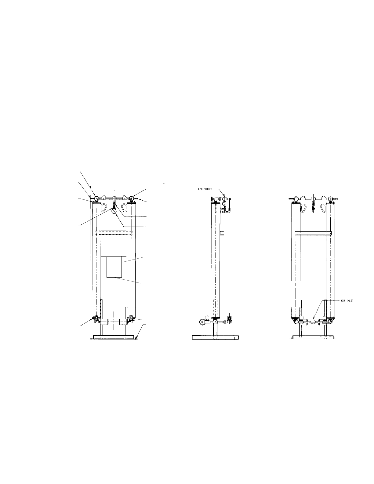
Left Tower Pressure
Gauge
Left Tower Pressure
Relief Valve
Desiccant Fill Port
Purge Pressure
Adjustment Valve
FIGURE 2B Models 25 through 80
Right Tower Pressure
Gauge
Right Tower
Pressure Relief Valve
Moisture
Indicator
Purge Pressure
Gauge
Control Panel
Desiccant Drain Port
Electrical Entry
(7/8")
Purge Muffler
3/4" Dia.
Mounting Holes
FRONT VIEW RIGHT SIDE VIEW REAR VIEW
7
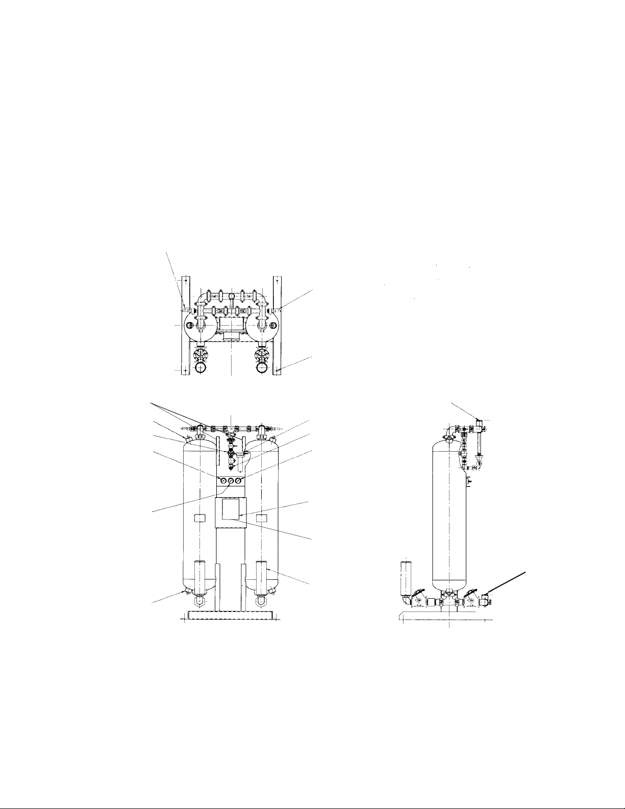
FIGURE 2C Models 115 through 2100
Left Tower Pressure
Relief Valve
C
D
A
B
*
*
L
Right Tower Pressure Relief Valve
3/4" (19mm) Dia. Mounting Holes
2" (51mm)
Lifting Lugs
Desiccant Fill Port
Purge Pressure Adjustment Valve
Left Tower Pressure Gauge
Purge Pressure Gauge
Desiccant Drain Port
E
"G" Air Outlet
Pilot Air Filter (Models 370 & larger)
Moisture Indicator
Right Tower
Pressure Gauge
Control Panel
Electrical Entry
(7/8")
Purge Muffler
*Models 115 through 260 use solenoid valves. Models 370 and larger use air operated butterfly valves.
K
F
"G" Air Inlet
*
*
J
H
8
 Loading...