

Hank HKZW-SCN04 Operating Manual
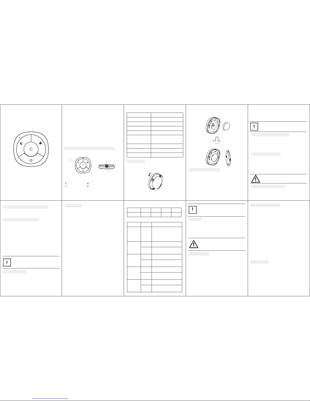
1. Prod uct lay out
OPERATING MANUA L
SCENE CON TR OL LE R
HKZW-SCN0 4- V1 .0
The Scene Controller is a slave product that is wireless, portable and
rechargeable . It can control a Z-Wave device, such as smart plug, smart
dimmer through a Z-Wave gateway. You can also activate a scene like
sleep scene, movie scene and entertainment scene with it.
The features list:
(1) Z-Wave Plus certified for wide compatibility (500 serials product).
(2) Support remote control anywhere and anytime.
(3) Scene Controller is capable of sending four different scene commands
with four buttons.
(4) The battery is rechargeable.
(5) The battery will run for half a year per single charging.
(6) Support low battery alarm with a buzzer.
(7) Support communication failure alarm with a buzzer.
(8) Support firmware OTA.
Ⅰ. GEN ERAL IN FORMATI ON ABOU T SCENE C ONTRO LLER
Radi o protoc ol:
Radi o freque ncy:
868. 42MHz ( EU) 908 .42MH z (US)
921. 42MHz ( AU)
Rang e:
Dime nsion s
50*5 0*16m m
36mA
3uA
Power s upply :
2. Spe cific ations
Sing le LIR2 450 3.6 V Batter y
Stora ge envir onmen t:
Opera tiona l tempe rature :
More t han 100 m outdo ors
Abou t 30m ind oors (d epend ing
on bui lding m ateri als)
Worki ng curre nt:
Stand by curr ent:
-10~ 50℃ 0%~ 85%
0~40 ℃
Z-Wave
LED
LED
Micro USB port
Ⅱ.INS TALLATION
Open the cove r:
Open the cove r, as the figure below shows .
Insert you r battery:
Insert you r battery and clos e the cover, as the figure belo w shows.
Ⅲ. Z-WAV E NETWO RK INCLU SION
Scene Cont roller can be incl uded and operate d in any Z-Wave
network wi th other Z-Wave cert ified device s from other
manufact urers and/or oth er applicati ons. All non-b attery operated
nodes with in the network wi ll act as repeaters rega rdless of vendo r
to increase re liability of t he network.
Include d as a non-secure dev ice
(1) Insert the LI R2450 battery.
(2) Set the Z-Wave net work main contro ller into learn ing mode
(see Z-Wave netw ork controlle r operating manu al).
(3) Triple click th e Z-button.
(4) If the incl usion is succes sful, the LED wil l blink in blue less th an
for 5 seconds and th en keep on for 15 seconds .
TIP:
If you want your Scene Controller to be a security device that
use secure/encrypted message to communicate in a Z-Wave
network, then a security enabled Z-Wave controller is needed.
To remove the Scene Controller from the Z-Wave network:
(1) Insert the LIR2450 battery.
(2) Set the Z-Wave network main controller into learning mode
(see Z-Wave controller operating manual).
(3) Triple click the Z-button, if the exclusion is successful, LED will blink
in orange for less than 5 seconds and then keep on for 3 seconds.
Ⅳ. REMOV ING FRO M Z-WAVE NE TWORK
Ⅴ. RESE T SCENE CO NTROL LER
Reset procedure clears the Scene Controller's memory, including
Z-Wave network information.
To reset Scene Controller:
Pressing and holding the Z-button for 20 seconds. Release the button
after 20 seconds, LED will keep in yellow for 3 seconds. Scene
Controller will be reset to factory defaults if you short press the
button within this 3 seconds.
Ⅵ. LOW BATTE RY ALAR M FUNCT ION
Scene Controller will send battery report to the lifeline group when
Z-Button is triggered during the sleep mode. If the battery level of
the Scene Controller is less than 20%, the Scene Controller will beep
3 times when the button is pressed.
Ⅶ. COM MUNIC ATION FAILU RE ALAR M FUNC TION
The Scene Controller will beep one time when the communication
between the Scene Controller and any one of the controlled device
is failed.
Ⅷ. TES TING Z- WAVE NETWO RK RANG E
Scene Controller's LED indicator can signal its communication quality
with the Z-Wave main controller.
To start testing:
Press and hold the Z-button for 11 to 15 seconds, the LED will keep on
in purple for 3 seconds, it will enter testing mode if you short press the
Z-button during these 3 seconds.
Blink in green –Scene Controller establish a direct communication with
the main controller, and still under checking.
Keep green – The green light should last about 2 seconds, which means
the direct communication is stable.
Blink in orange –Scene Controller can communicate with the main
controller in intermediate radio transmit power level, and still under
checking.
Keep orange – The communication quality is moderate.
Keep Red – The communication is failed.
TIP:
1. Thi s funct ion wor ks only wh en Scen e Contr oller
has be en incl uded in to a Z-Wave n etwor k.
2. Cli ck the Z bu tton to ex it the tes t.
Ⅸ. BATTE RY CHAR GING
Scene Controller has an internal rechargeable battery that will run for
half a year under the normal use condition. If the battery level is less
than 20%, this will activate the low battery level function, this means
you need to charge the battery.
The charger's output should be a micro USB terminal with the
specification of output DC 5V.
The LED nearby the micro USB port will keep on in red during the
changing, and it will turn to green if the charging is finished.
Ⅹ. ASSO CIATION
Association allows the Scene Controller to control another Z-Wave
device directly, such as Smart Switch, Smart Dimmer, etc.
Scene Controller supports nine association groupings, every group
relates to a specific button action. View details in the follow
section of “Ⅻ. BUTTON FUNCTION”.
Group 1 allows Scene Controller sends central scene notification
command and battery report command when any button is triggered.
Details shown as the below diagram 1.
Group 2 allows Scene Controller sends basic set command when the
button 1 is triggered.
Group 3 allows Scene Controller sends switch multilevel set, multilevel
start level change and multilevel stop level change command when the
button 1 is triggered.
Group 4 allows Scene Controller sends basic set command when the
button 2 is triggered.
Group 5 allows Scene Controller sends switch multilevel set, multilevel
start level change and multilevel stop level change command when the
button 2 is triggered.
Group 6 allows Scene Controller sends basic set command when the
button 3 is triggered.
Group 7 allows Scene Controller sends switch multilevel set, multilevel
start level change and multilevel stop level change command when the
button 3 is triggered.
Group 8 allows Scene Controller sends basic set command when the
button 4 is triggered.
Group 9 allows Scene Controller sends switch multilevel set, multilevel
start level change and multilevel stop level change command when the
button 4 is triggered.
Details shown as the below diagram 2
Included as a secure device
(1) Insert the LIR2450 battery.
(2) Set the Z-Wave network main controller into learning mode
(see Z-Wave network controller operating manual).
(3) Pressing and holding the Z-button for 3 seconds.
(4) If the inclusion is successful, the LED will blink in green less than
for 5 seconds and then keep on for 15 seconds.
NOTE:
Use this procedure only in the event that the network
primary controller is missing or otherwise inoperable.
mean s Button 1 m eans Bu tton 2
mean s Button 3 m eans Bu tton 4
Butto n ID
Scen e Numbe r
1122334
4
Butto n ID
Any but ton
Group I D
1
Acti on & noti ficati on
Press: Central scene notification
( Key Attributes=0)
Hold: Central scene notification
( Key Attributes=2)
Release: Central scene notification
( Key Attributes=1)
Diagram 2:
Butto n 1 2 Press: Basic Set Hold: Reserve
Release: Reserve
3
Press: Switch multilevel set
Hold: Multilevel start level change
Release: Multilevel stop level change
Butto n 2 4 Press: Basic Set Hold: Reserve
Release: Reserve
5
Press: Switch multilevel set
Hold: Multilevel start level change
Release: Multilevel stop level change
Butto n 3 6 Press: Basic Set Hold: Reserve
Release: Reserve
7
Press: Switch multilevel set
Hold: Multilevel start level change
Release: Multilevel stop level change
Butto n 4 8 Press: Basic Set Hold: Reserve
Release: Reserve
9
Press: Switch multilevel set
Hold: Multilevel start level change
Release: Multilevel stop level change
TIP:
1. The max number of associated nodes of all these
9 groups is 5.
2. Association allows for direct transmission of control
command between devices and takes place without the
participation of the main controller.
Ⅺ. WAKE UP
Wake up interval:
Available settings: 0
Default setting: 0
Pressing and holding Z-Button for 3 seconds. Led will turn to green,
which means Scene Controller has successfully sent the wake up
notification out.
NOTE:
The interval time must be set to 0. The wake up
notification will not wake the Scene Controller, only the
action of the button can you wake the Scene Controller.
Ⅻ. BUTTON FUNCTION
Scene Controller offers three button action types, including short
press, held down and release.
Short press allows Scene Controller sends:
Central scene notification command to the associated nodes,
Basic set command to the associated nodes.
Switch multilevel set command to the associated nodes.
Held down (more than 1 second less than 20 seconds) allows Scene
Controller sends:
Central scene notification command to the associated nodes,
Multilevel start level change command to the associated nodes.
Release allows Scene Controller sends:
Central scene notification command to the associated nodes,
Multilevel stop level change command to the associated nodes.
XIII. ADVANCED CONFIGURATION
Scene Controller offers a wide variety of advanced configuration
settings. Below parameters can be accessed from main controllers
configuration interface.
Parameter No.254 Enable/disable the configuration command
Lock/unlock all configuration parameters.
0 – Unlock.
1 – Lock.
Default setting: 0
Parameter size: 1[byte]
Parameter No.255 Reset Scene Controller
Reset the sensor or remove from the Z-Wave network
Value: 1431655765
Default: 1
Parameter size: 4[byte]
Reset to factory default settings and removed from the Z-Wave network.
Value: 85
Default: 1
Parameter size: 1[byte]
Reset the values of the configuration command to default setting.
You may need the Over the Air (OTA) feature for the product's
firmware upgrade. Your Scene Controller can not be used after OTA.
In such a case, you need to activate the product by pressing and
holding the Z-Button until the led turns on, this procedure may take
you about 10 seconds. After these your Scene Controller will be usable.
XIV. NOTES FOR OTA
Diagram 1:
 Loading...