


1 Product Overview
Tuya TYZS4 Zigbee Module
Version: 2.0.0
Date: 2019-07-26
No.:
Global Intelligent Platform
TYZS4 is a low-power embedded Zigbee module that Hangzhou Tuya Inc. has developed.
It consists of a highly integrated wireless radio processor chip
(EFR32MG1B232F256GM48-C0) and several peripheral components, with an embedded
802.15.4 PHY/MAC Zigbee network protocol stack and robust library functions. TYZS4 is
embedded with a low-power 32-bit ARM Cortex-M4 core, 256 KB flash memory, and 32
KB random-access memory (RAM), and has extensive peripherals.
TYZS4 is a FreeRTOS platform that integrates all the function libraries of the Zigbee MAC
protocol. You can develop built-in Zigbee products as required.
1.1 Features
Embedded low-power 32-bit ARM Cortex-M4 processor, which provides digital signal
processor (DSP) instructions and floating-point units (FPUs) and also functions as an
application processor
Dominant frequency: 40 MHz
Working voltage: 1.8 V to 3.8 V
Peripherals: four GPIOs and one universal asynchronous receiver/transmitter (UART)
that supports flow control
Zigbee features
Tuya Inc. V2.0.0

802.15.4 MAC/PHY
Working channels 11 to 26 at 2.400 GHz to 2.483 GHz; 250 kbit/s air interface
rate
Embedded DC-DC circuit, maximizing the power efficiency
Maximum output power: +10 dBm; dynamic output power: > 35 dB
Runtime power consumption: 63 µA/MHz; current in sleep mode: 1.4 µA
Proactive network configuration for terminals
Onboard PCB antenna
The module also contains a PCB print antenna with 2.2 dBi gain.
Working temperature: –20°C to +85°C
AES-128/AES-256 hardware encryption
Wireless air interface packet capture
1.2 Applications
Intelligent building
Smart household and home appliances
Intelligent socket and light
Industrial wireless control
Health care and measurement
Asset tracing
Tuya Inc. V2.0.0

Change History
No.
Date
Change Description
Version After Change
1
2019-08-06
Updated the document template.
2.0.0
Tuya Inc. V2.0.0

Contents
1 Product Overview.....................................................................................................................1
1.1 Features.........................................................................................................................1
1.2 Applications...................................................................................................................2
2 Module Interfaces.....................................................................................................................5
2.1 Dimensions and Footprint...........................................................................................5
2.2 Pin Definition.................................................................................................................5
2.3 Test Pin Definition........................................................................................................ 7
3 Electrical Parameters.............................................................................................................. 7
3.1 Absolute Electrical Parameters................................................................................. 7
3.2 Electrical Conditions....................................................................................................8
3.3 Zigbee TX Power Consumption.................................................................................8
3.4 Zigbee RX Power Consumption................................................................................ 9
3.5 Working Current........................................................................................................... 9
4 RF Features.............................................................................................................................. 9
4.1 Basic RF Features.......................................................................................................9
4.2 Zigbee Output Performance.....................................................................................10
4.3 Zigbee RX Sensitivity................................................................................................10
5 Antenna Information.............................................................................................................. 11
5.1 Antenna Type..............................................................................................................11
5.2 Antenna Interference Reduction..............................................................................11
6 Packaging Information and Production Instructions........................................................ 12
6.1 Mechanical Dimensions............................................................................................12
6.2 Recommended PCB Encapsulation.......................................................................13
6.3 Production Instructions............................................................................................. 14
6.4 Recommended Oven Temperature Curve.............................................................15
6.5 Storage Conditions....................................................................................................16
7 Appendix..................................................................................................................................16
Tuya Inc. V2.0.0
2 Module Interfaces
Pin No.
Symbol
I/O Type
Function
1
nRST
I
Hardware reset pin. When the pin is at a low level,
the chip is reset. TYZS4 is reset upon power-on, and
therefore, this pin may not be used.
2
FRC_DCLK
I/O
Packet trace interface (PTI) clock signal.
3
SWDIO
I/O
J-Link SWDIO programming pin. It can be configured
2.1 Dimensions and Footprint
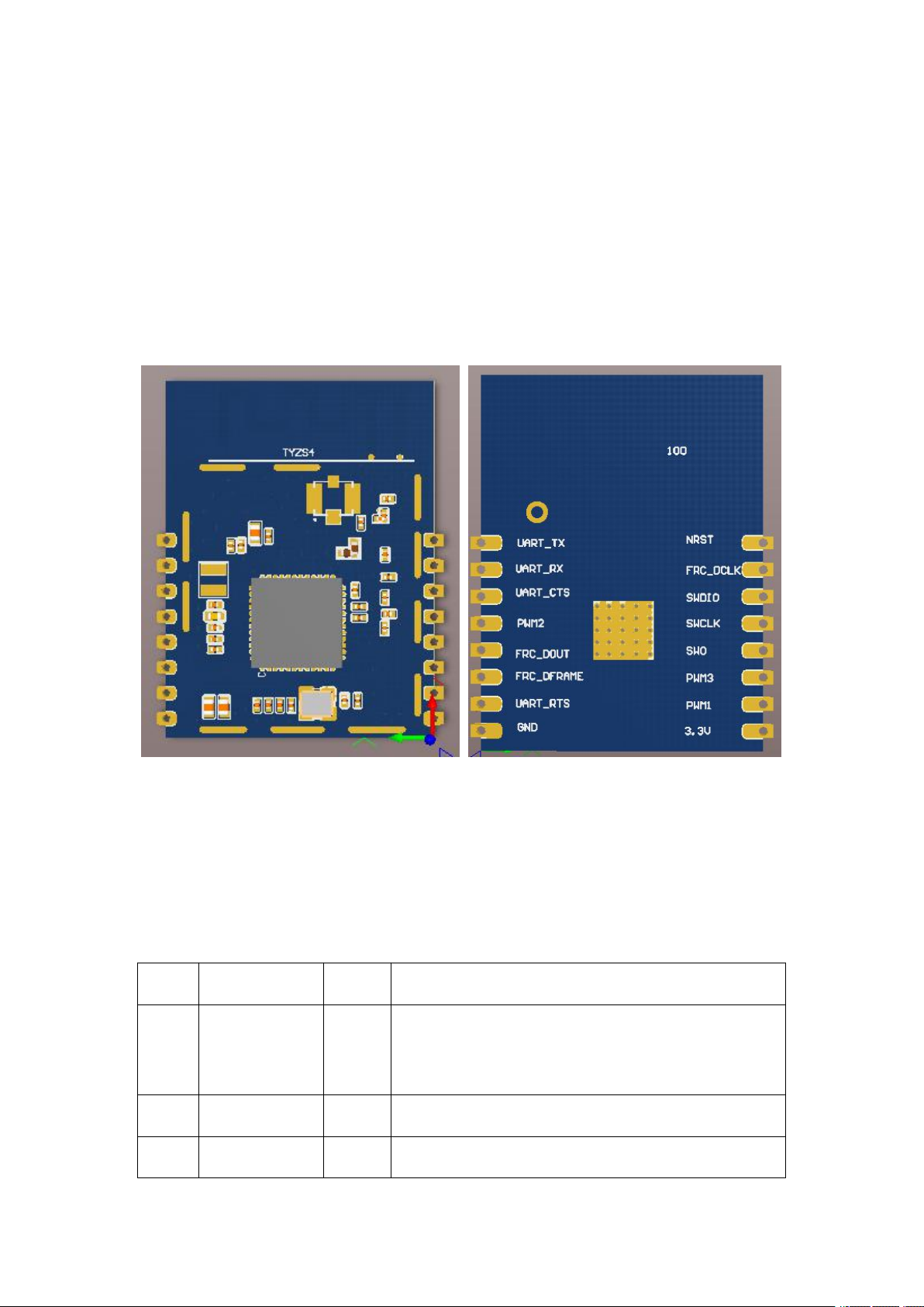
TYZS4 has two rows of pins with a 2 mm pin spacing.
TYZS4 dimensions (H x W x D): 3.5±0.1 mm x 21±0.35 mm x 28±0.35 mm
Figure 2-1 shows the TYZS4 front and rear views.
Figure 2-1 TYZS4 front and rear views
2.2 Pin Definition
Table 2-1 TYZS4 interface pins
Tuya Inc. V2.0.0

Pin No.
Symbol
I/O Type
Function
as a GPIO in actual application programs.
4
SWCLK
I/O
J-Link SWCLK programming pin. It can be configured
as a GPIO in actual application programs.
5
SWO
I/O
Used as an output pin in J-Link debugging
communication state or a GPIO in actual application
programs.
6
PWM3
I/O
Used as a GPIO. It supports Packet Traffic Arbitration
(PTA).
7
PWM1
I/O
Used as a GPIO. It supports PTA.
8
VCC
P
Power supply pin. The typical power supply voltage
is 3.3 V.
9
GND
P
Reference ground pin.
10
UART_RTS
I/O
Reserved serial interface UART RTS signal. This pin
is connected to the external CTS pin on the MCU. It
can also be used as a GPIO in actual application
programs.
11
FRC_DFRAME
I/O
Debugging PTI; frame signal.
12
FRC_DOUT
I/O
Debugging PTI, data signal.
13
PWM2
I/O
Reserved PWM output pin. It supports PTA.
14
UART_CTS
I/O
Reserved serial interface UART CTS signal. This pin
is connected to the external RTS pin on the MCU.
15
RXD
I/O
UART0_RXD, used for receiving over the serial
interface. This pin is connected to UART_TX of the
upper computer.
16
TXD
Output
UART0_TXD, used for sending over the serial
interface. This pin is connected to UART_RX of the
upper computer.
Note:
1. P indicates power supply pins, I/O indicates input/output pins, and AI indicates analog
input pins.
Tuya Inc. V2.0.0

2. nRST is only a hardware reset pin. It cannot clear the Zigbee network configuration
Pin No.
Symbol
I/O Type
Function
N/A
N/AIUsed for the module production test
Parameter
Description
Minimum
Value
Maximum
Value
Unit
Ts
Storage temperature
–50
150
°C
VCC
Power supply voltage
–0.3
3.8
V
Static electricity voltage
(human body model)
Tamb = 25°C
N/A
2.5
kV
Static electricity voltage
(machine model)
Tamb = 25°C
N/A
0.5
kV
information.
3. As shown in Figure 2-1, Pin1 (the nRST pin) and Pin16 (the TXD pin) are respectively
on the upper left and upper right of the module's front side.
2.3 Test Pin Definition
Table 2-2 TYZS4 test pins
Note: It is not recommended that test pins be used.
3 Electrical Parameters
3.1 Absolute Electrical Parameters
Table 3-1 Absolute electrical parameters
Tuya Inc. V2.0.0

3.2 Electrical Conditions
Parameter
Description
Minimum
Value
Typical
Value
Maximum
Value
Unit
Ta
Working temperature
–20
N/A85°C
VCC
Working voltage
1.8
3.3
3.8
V
VILI/O low-level input
–0.3
N/A
VCC x 0.25
V
VIHI/O high-level input
VCC x 0.75
N/A
VCC
V
VOLI/O low-level output
N/A
N/A
VCC x 0.1
V
VOHI/O high-level output
VCC x 0.8
N/A
VCC
V
Imax
I/O drive current
N/A
N/A12mA
Symbol
Parameter
Typical Value
Unit
Rate
TX Power
IRF250 kbit/s
+19 dBm
120
mA
IRF250 kbit/s
+13 dBm
50
mA
IRF250 kbit/s
+10 dBm
32
mA
IRF250 kbit/s
+4 dBm
17
mA
IRF250 kbit/s
+1 dBm
11.8
mA
Table 3-2 Normal electrical conditions
3.3 Zigbee TX Power Consumption
Table 3-3 Power consumption during constant transmission
Note: When the preceding data is being tested, the duty cycle is set to 100%.
Tuya Inc. V2.0.0

3.4 Zigbee RX Power Consumption
Symbol
Rate
Typical Value
Unit
IRF250 kbit/s
8
mA
Working
Mode
Working Status (Ta = 25°C)
Average
Value
Maximum
Value
Unit
EZ
The module is in EZ mode.
1040mA
Connected
The module is connected to the
network.
35mA
Deep sleep
mode
The module is in deep sleep mode,
with 64 KB flash memory.
1.43μA
Parameter
Description
Frequency band
2.400 GHz to 2.484 GHz
Physical-layer standard
IEEE 802.15.4
Data transmission rate
250 kbit/s
Antenna type
Default PCB antenna or external antenna used with
an I-PEX connector
Table 3-4 Power consumption during constant receiving
Note: When the UART is in active state, the receiving current is 14 mA.
3.5 Working Current
Table 3-5 TYZS4 working current
4 RF Features
4.1 Basic RF Features
Table 4-1 Basic RF features
Tuya Inc. V2.0.0

Parameter
Description
Line-of-sight transmission
distance
200 m
4.2 Zigbee Output Performance
Parameter
Minimum
Value
Typical
Value
Maximum
Value
Unit
Maximum output power
N/A
+19
N/A
dBm
Minimum output power
N/A
–30
N/A
dBm
Output power adjustment step
N/A
0.51dB
Frequency error
–15
N/A
+15
ppm
Output spectrum adjacent-channel rejection
ratio
–31
dBc
Parameter
Minimum
Value
Typical
Value
Maximum
Value
Unit
PER < 10%, 250 kbit/s, OQPSK
N/A
–101
N/A
dBm
Table 4-2 Performance during constant transmission
Note: The maximum output power can reach +19 dBm. The output power can be adjusted
under normal use. The high-power output can be used for coverage in extremely complex
conditions, for example, gateway-level indoor or outdoor coverage.
4.3 Zigbee RX Sensitivity
Tuya Inc. V2.0.0
Table 4-3 RX sensitivity

5 Antenna Information
5.1 Antenna Type
By default, TYZS4 uses an onboard PCB antenna.
5.2 Antenna Interference Reduction
To ensure optimal wireless performance when the Zigbee module uses an onboard PCB
antenna, it is recommended that the antenna be at least 15 mm away from other metal
parts and that the antenna location on the PCB be hollowed out.
To prevent adverse impact on the antenna radiation performance, avoid copper or traces
along the antenna area on the PCB, as shown in the following Figure 5-1.
For details about the onboard PCB antenna area on TYZS4, see Figure 6-1.
Figure 5-1 Antenna placement
Tuya Inc. V2.0.0

6 Packaging Information and Production Instructions
6.1 Mechanical Dimensions
Figure 6-1 TYZS4 mechanical dimensions
Tuya Inc. V2.0.0

6.2 Recommended PCB Encapsulation
Figure 6-2 TYZS4 schematic diagram and pin connection
Figure 6-3 shows the connection between TYZS4 as a gateway module and an external
MCU. The PWM1, PWM2, and PWM3 pins are reserved.
Figure 6-3 Connection between TYZS4 as a gateway module and an external MCU
(without PTA)
Tuya Inc. V2.0.0

Figure 6-3 Description of connection between TYZS4 as a gateway module and an
external MCU (with PTA)
The following attachment is an encapsulation dimensions library file.
You can directly reference the encapsulation file in Altium Designer format during
encapsulation design.
6.3 Production Instructions
Storage conditions for a delivered module are as follows:
1. The moisture-proof bag is placed in an environment where the temperature is below
30°C and the relative humidity is lower than 85%.
2. The shelf life of a dry-packaged product is six months from the date when the product
is packaged and sealed.
Precautions:
1. Throughout the production process, each involved operator must wear an ESD wrist
strap and ESD suit.
2. During the operation, strictly protect the module from water and stains.
Tuya Inc. V2.0.0

6.4 Recommended Oven Temperature Curve
Tuya Inc. V2.0.0

6.5 Storage Conditions
7 Appendix
Federal Communications Commission (FCC) Declaration of Conformity
FCC Caution: Any changes or modifications not expressly approved by the party
responsible for compliance could void the user's authority to operate this equipment.
This device complies with Part 15 of the FCC Rules.
Operation is subject to the following two conditions: (1) This device may not cause harmful
interference, and (2) this device must accept any interference received, including
interference that may cause undesired operation.
Tuya Inc. V2.0.0

15.105 Information to the user.
(b) For a Class B digital device or peripheral, the instructions furnished the user shall
include the following or similar statement, placed in a prominent location in the text of the
manual:
Note: This equipment has been tested and found to comply with the limits for a Class B
digital device, pursuant to part 15 of the FCC Rules.
These limits are designed to provide reasonable protection against harmful interference in
a residential installation. This equipment generates, uses and can radiate radio frequency
energy and, if not installed and used in accordance with the instructions, may cause
harmful interference to radio communications. However, there is no guarantee that
interference will not occur in a particular installation. If this equipment does cause harmful
interference to radio or television reception, which can be determined by turning the
equipment off and on, the user is encouraged to try to correct the interference by one or
more of the following measures:
—Reorient or relocate the receiving antenna.
—Increase the separation between the equipment and receiver.
—Connect the equipment into an outlet on a circuit different from that to which the
receiver is connected.
—Consult the dealer or an experienced radio/TV technician for help.
This equipment complies with FCC radiation exposure limits set forth for an uncontrolled
environment. This equipment should be installed and operated with minimum distance 20
cm between the radiator and your body.
Radiation Exposure Statement:
This equipment complies with FCC radiation exposure limits set forth for an uncontrolled
environment.
This transmitter must not be co-located or operating in conjunction with any other antenna
or transmitter.
The availability of some specific channels and/or operational frequency bands is country
dependent and firmware programmed at the factory to match the intended destination.
Tuya Inc. V2.0.0

The firmware setting is not accessible by the end user.
The final end product must be labeled in a visible area with the following:
"Contains Transmitter Module 2ANDL-TYWXXX"
TYZS4 Module FCC ID: 2ANDL-TYZS4
This radio module must not be installed to co-locate and operating simultaneously with
other radios in host system, additional testing and equipment authorization may be
required to operating simultaneously with other radio.
Declaration of Conformity European notice
Hereby, Hangzhou AiXiangJi Technology Co., Ltd declares that this Wi-Fi module product
is in compliance with essential requirements and other relevant provisions of Directive
2014/53/EC. A copy of the Declaration of conformity can be found at http://www.tuya.com.
EN 300 328 V2.1.1
EN 301 489-1 V2.1.1; EN 301 489-17 V3.1.1
EN 62311:2008
EN 60950-1:2006+A11:2009+A1:2010+A12:2011+A2:2013
Tuya Inc. V2.0.0
 Loading...