

TYLC6 Datasheet
Tuya Inc.
V1.0.0
Tuya Smart Wi-Fi Module
1 Product Overview
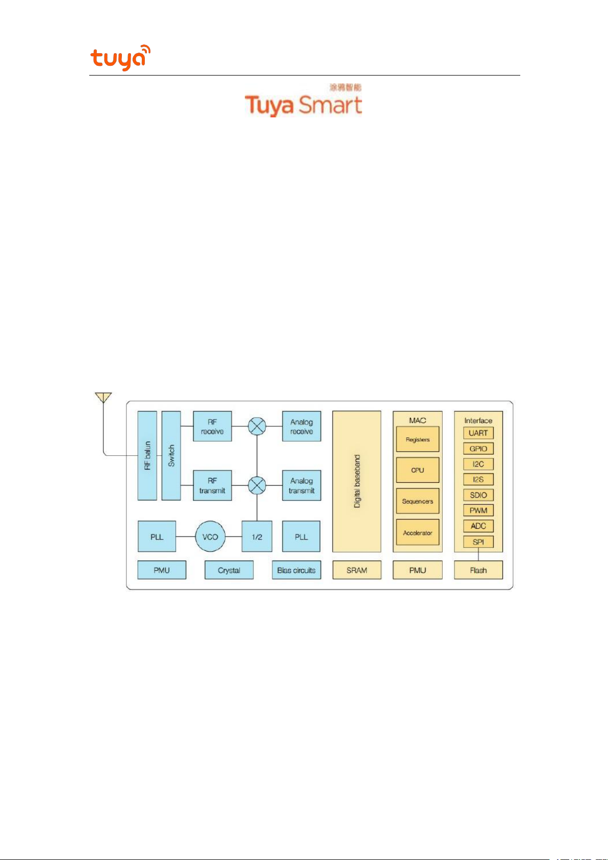
TYLC6 is a low power-consuming built-in Wi-Fi module developed by Hangzhou Tuya Inc. It
consists of a highly integrated RF microchip (ESP8285) and several peripheral components, with a
built-in Wi-Fi network protocol stack and robust library functions. TYLC6 is embedded with a 32-
bit CPU with low power consumption, 1 MB flash memory, 50 KB SRAM, and rich peripheral
resources.
TYLC6 is an RTOS platform that integrates all the function libraries of the Wi-Fi MAC and TCP/IP
protocols. You can develop built-in Wi-Fi products as required.
Figure 1 shows the architecture of TYLC6.
1.1 Features
Built-in low power-consuming 32-bit CPU functioning as an application processor
Working voltage: 3.0 V to 3.6 V
Peripherals: three GPIOs
Wi-Fi connectivity
Figure 1 TYLC6 architecture
Basic frequencies: 80 MHz and 160 MHz
802.11b/g/n

Tuya Inc.
V1.0.0
TYLC6 Datasheet
Channels 1 to 14 at 2.4 GHz
WPA/WPA2 security mode
Up to +20 dBm EIRP output power in 802.11b mode
STA/AP/STA+AP working mode
SmartConfig and AP network configuration modes (for Android and iOS devices)
External welded helical spring antenna
Working temperature: –20°C to +105°C
1.2 Applications
Intelligent building
Smart home and household appliances
Intelligent socket and light
Industrial wireless control
Baby monitor
Network camera
Intelligent bus

Tuya Inc.
V1.0.0
TYLC6 Datasheet
Contents
1 Product Overview......................................................................................................................... 1
1.1 Features...................................................................................................................................1
1.2 Applications............................................................................................................................2
2 Module Interfaces......................................................................................................................... 5
2.1 Dimensions and Footprint...................................................................................................... 5
2.2 Pin Definition..........................................................................................................................5
2.3 Test Pin Definition..................................................................................................................6
3 Electrical Parameters.................................................................................................................... 6
3.1 Absolute Electrical Parameters...............................................................................................6
3.2 Electrical Conditions.............................................................................................................. 6
3.3 Wi-Fi TX Power Consumption...............................................................................................7
3.4 Wi-Fi RX Power Consumption...............................................................................................7
3.5 Working Power Consumption.................................................................................................7
4 RF Features...................................................................................................................................8
4.1 Basic RF Features...................................................................................................................8
4.2 Wi-Fi Output Power................................................................................................................8
4.3 Wi-Fi RX Sensitivity.............................................................................................................. 8
5 Antenna Information.....................................................................................................................9
5.1 Antenna Types.........................................................................................................................9
5.2 Antenna Interference Reduction.............................................................................................9
6 Packaging Information and Production Instructions..................................................................10
6.1 Mechanical Dimensions....................................................................................................... 10
6.2 Recommended PCB Encapsulation......................................................................................10
6.3 Production Instructions.........................................................................................................11
6.4 Recommended Oven Temperature Curve............................................................................. 11

Tuya Inc.
V1.0.0
TYLC6 Datasheet
Figures
Figure 1 TYLC6 architecture........................................................................................................1
Figure 2 TYLC6 dimensions........................................................................................................ 5
Figure 3 Antenna dimensions....................................................................................................... 9
Figure 4 TYLC6 mechanical dimensions (unit: mm).................................................................10
Figure 5 PCB thickness.............................................................................................................. 10
Tables
Table 1 TYLC6 interface pins...................................................................................................... 5
Table 2 TYLC6 test pins...............................................................................................................6
Table 3 Absolute electrical parameters.........................................................................................6
Table 4 Normal electrical conditions............................................................................................6
Table 5 TX power consumption during constant emission.......................................................... 7
Table 6 RX power consumption during constant receiving......................................................... 7
Table 7 TYLC6 operating current.................................................................................................7
Table 8 Basic RF features.............................................................................................................8
Table 9 TX power during constant emission................................................................................ 8
Table 10 RX sensitivity.................................................................................................................8
Tuya Inc.
V1.0.0
TYLC6 Datasheet
2 Module Interfaces
No.
Symbol
I/O Type
Function
1
GPIO14
I/O
GPIO_14
2
VCC
P
Module power supply pin (3.3 V)
3
GPIO12
I/O
GPIO_12
4
GND
P
Power supply reference ground pin
5
GPIO13
I/O
GPIO_13
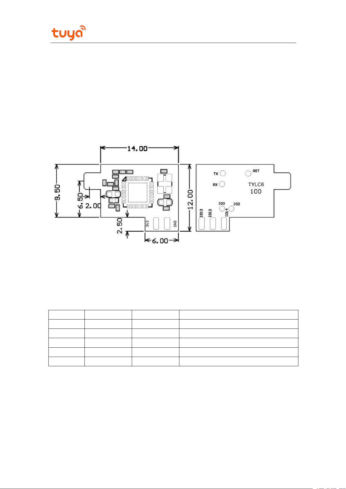
2.1 Dimensions and Footprint
TYLC6 has two rows of pins with a 2 mm pin pitch.
Dimensions (H x W x D) of TYLC6 are as follows: 3 mm x 12 mm x 14 mm. The error tolerance is
±0.3 mm. Figure 2 shows the dimensions of TYLC6.
Figure 2 TYLC6 dimensions
2.2 Pin Definition
Table 1 TYLC6 interface pins
Note: P indicates power-supply pins, and I/O indicates input/output pins.
 Loading...