


TYLC4v1.0.0 User manual
1. Product Overview
TYLC4 is a low-power embedded Wi-Fi module developed by Hangzhou Tuya Information
Technology Co., Ltd., which consists of a highly integrated RF chip ESP8266 and a few
peripheral components with built-in Wi-Fi network protocol stack and abundant library functions.
TYLC4 is embedded with low power 32-bit CPU, 1 Mbyte flash memory and rich peripheral
resources.
TYLC4 is a RTOS platform which integrates all the function libraries of Wi-Fi MAC and
TCP/IP protocol, base on which, users are enabled to develop embedded Wi-Fi products according
to their specific requirements.
1.1 Features
The embedded low-power 32-bit CPU can also be used as application processor
CPU Clock Speed: 80MHz and 160MHz
Working voltage: 3.0V-3.6V
Peripheral: 5×GPIOs, 1×UART
Wi-Fi connectivity
802.11 b/g/n
Channels 1-11@2.4GHz
In support of WPA/WPA2 safe mode
In support of STA/AP/STA+AP operating mode
In support of two distribution networks including SmartConfig and AP(Android and
IOS devices included)
Operating temperature: -20℃ to 125℃
1.2 Main applications
Intelligent building
Smart home/home appliances
Smart power
Industrial wireless control
Baby monitors
Webcams
Intelligent public transportation
plug, intelligent light
TYLC4v1.0.0 User manual
Version1.0.0
4
2. Module Interfaces
2.1 Size Package
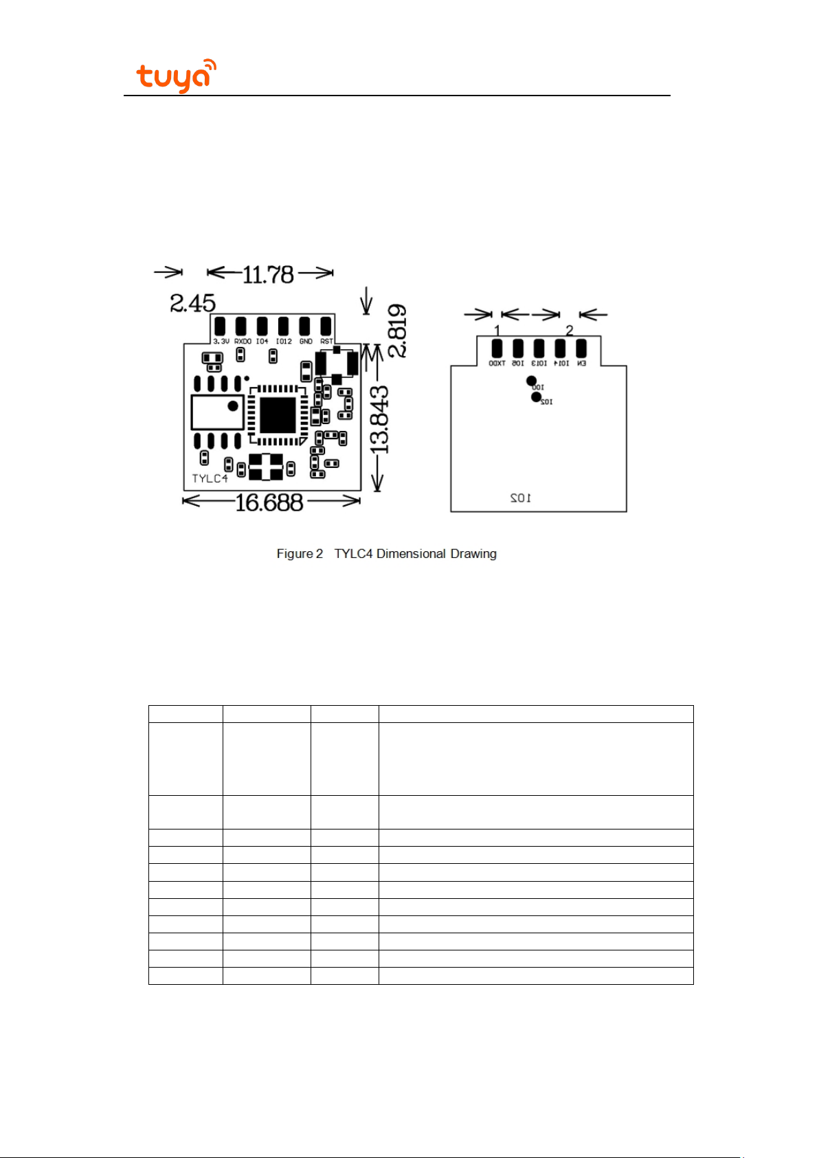
TYLC4 has two rows of pins and the spacing between each two pins is 2mm.
TYLC4 size: 16.69mm (W)×16.66mm (L) ×3.5mm (H). TYLC4 size is shown in figure2:
Figure 2.1, TYLC4 dimensional drawing
2.2 Pin definition
The interface pin definition is shown in Chart 1:
Chart 1 TYLC4 Interface Pin Configuration Instruction
Table 2.1,WR1 pins description
Pin Symbol IOType Function
1 RST I/O
2 EN I
3 GND P Power reference ground
4 GPIO14 I/O GPIO_14
5 GPIO12 I/O GPIO_12
6 GPIO13 I/O GPIO_13
7 GPIO4 I/O GPIO_04
8 GPIO5 I/O GPIO_05
9 RXD0 I/O UART0_RXD 1
10 TXD0 O UART0_TXD 1
11 VCC P Module’s power pin (3.3V)
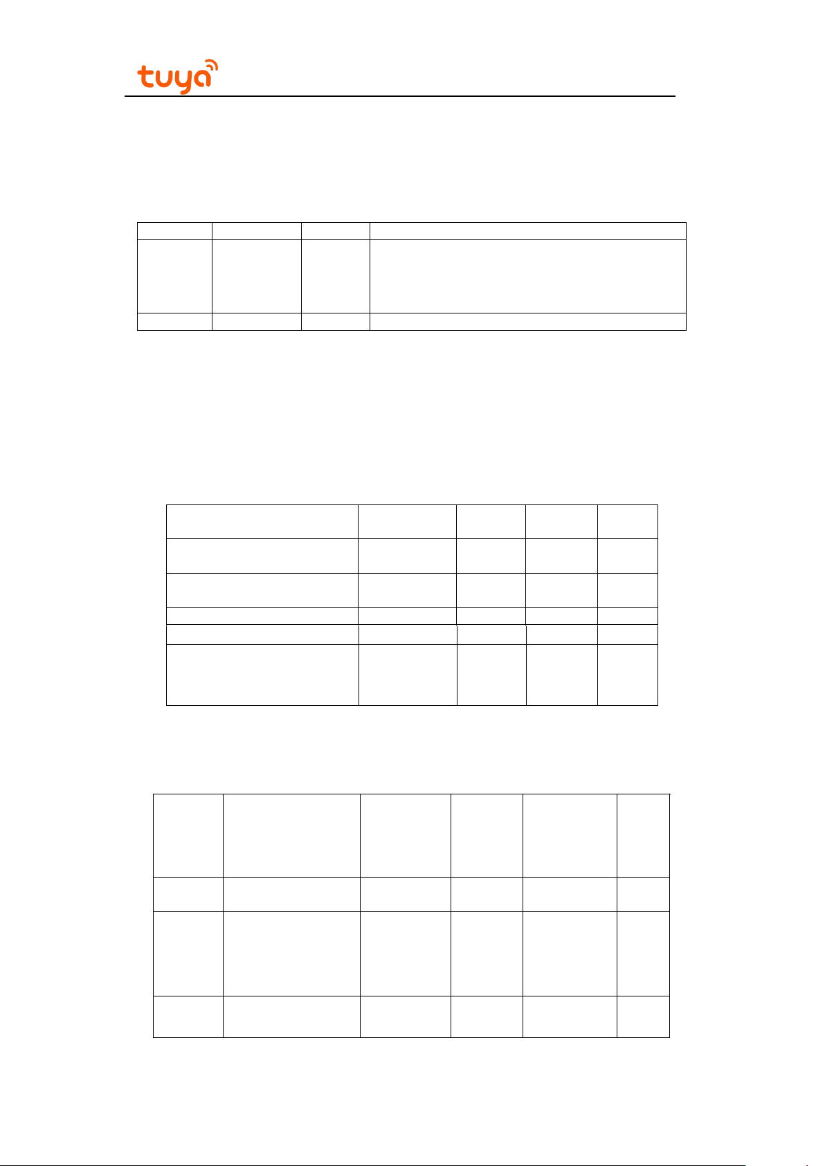
Notes: P stands for power pin, I/O stands for input/output pin.
RST is only the module hardware reset pin, which cannot erase WiFi distribution network
information.
Hardware reset pin (effective at low electrical
level, with pull-up resistor inside)
Module enabling pin needs to receive 3.3V power
supply
TYLC4v1.0.0 User manual
Version1.0.0
5
(1): UART0 is the user
information output and user can ignore it.
serial port; when the module is powered up, the serial port has
2.3 Test Point Definition
The test pin definition is shown in Chart 2:
Chart 2 TYLC4 Test Pin Configuration Instruction
Pin Symbol IOType Function
- TEST1 I/O GPIO2, used for module production test
- TEST2 I/O GPIO0, used for module production test
3. Electrical Parameters
3.1 Absolute electrical parameters
Chart 3 Absolute Parameters
Parameters Description
Ts
VCC
Electrostatic Discharge TAMB-25℃ - 2 KV
Voltage (human
model)
Storage
temperature
Supply
voltage
Minimu
m value
Maximu
m value
-20 85 ℃
-0.3 3.6 V
Unit
Electrostatic Discharge
Voltage (machine model)
3.2 Operating
Paramet
ers
Ta
VCC
Operating voltage 3.0 3.3 3.6
VIL
conditions
IO low electrical
TAMB-25℃ - 0.5 KV
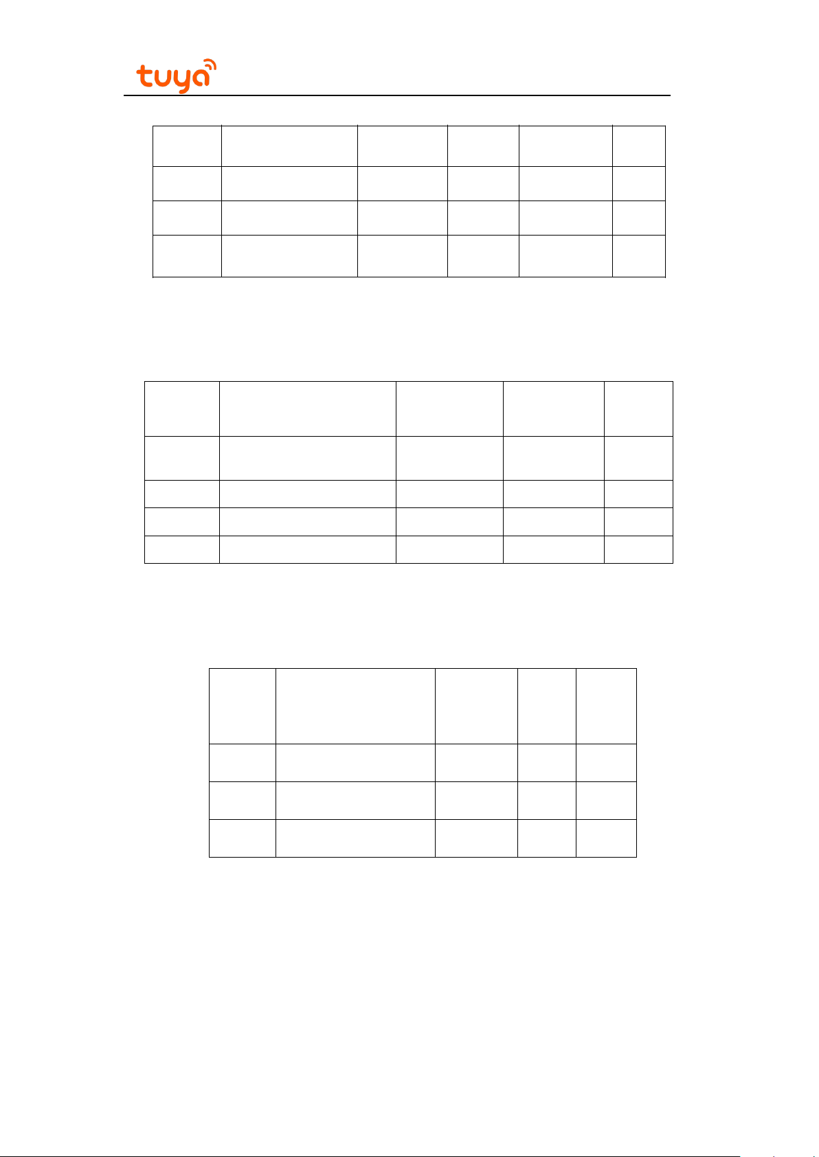
Chart 4 Normal Operating Conditions
Description Min Typ Max Unit
Operating
temperature
level
input
-20 - 125 ℃
-0.3 -
V
VCC*0.25 V
TYLC4v1.0.0 User manual
Version1.0.0
6
VIH
VOL
VoH
Imax IO drive current - - 12 mA
IO high electrical
level input
IO low electrical
level output
IO high electrical
level output
VCC*0.75 - VCC V
- - VCC*0.1 V
VCC*0.8 - VCC V
3.3 Wi-Fi Transmitting Power
Chart 5 TX Continuous Transmitting Power
Symbol Mode Power Typ Unit
Mode Mode Rate
IRF 11b 1Mbps
IRF 11g 6Mbps
Transmitting
Power
+19.40
+21.74
dBm
dBm
IRF 11n MCS0 +21.26 dBm
3.4 Wi-Fi Receiving Power
Chart 6 RX Continuous Receiving
Symbol
IRF 11b 1Mbps 76
IRF 11g 6Mbps 76
IRF 11n
Mode
Rate
MCS0
Typ
76
Unit
mA
mA
mA
3.5 Power in Operating Mode

TYLC4v1.0.0 User manual
Version1.0.0
7
Chart 7 TYLC4 Operating Current
Operation
Mode
Fast connection
distribution
network
Hot spot
distribution
network
Internet
connection
Offline
When the module is in a state of fast connection
distribution network, WiFi indicator light flashes
When the module is in a state of hot spot
distribution network, WiFi indicator light flashes
When the module is with internet connection,
When the module is offline, WiFi indicator light
4. RF Characteristics
Operating condition, TA=25℃ Typ Peak Unit
80 151 mA
quickly
90 451 mA
slowly
WiFi indicator light goes on
goes out
58.5 411 mA
80 430 mA
4.1 Basic RF characteristics
Chart 8 RF Basic Characteristics
Parameter Description
Operating
frequency
Wi-Fi standard IEEE 802.11b/g/n (channel 1-11)
Data transmitting
rate
Antenna type
11b:1,2,5.5, 11 (Mbps) 11g:6,9,12,18,24,36,48,54(Mbps)
One welding monopole antenna for TYLC4, TYLC4-IPEX
has one replaceable IPEX Connector, using monopole antenna
or FPC antenna
2.412~2.462GHz
11n:HT20 MCS0~7

TYLC4v1.0.0 User manual
Version1.0.0
8
4.2 Wi-Fi output power
Chart 9 TX Continuous Transmitting Power
Parameter Min Typ Max Unit
RF average output power, 802.11b CCK Mode 1Mbps - - dBm
RF average output power, 802.11g OFDM Mode 6Mbps
RF average output power, 802.11n OFDM Mode MCS0 - - dBm
Frequency Error - -10 - 10 ppm
4.3 Wi-Fi RX sensitivity
Chart 10 RX Sensitivity
Parameter Min Typ Max Unit
PER<8%,RX sensitivity, 802.11b CCK Mode
PER<10%,RX sensitivity, 802.11g OFDM Mode
PER<10%,RX sensitivity, 802.11n OFDM Mode
1Mbps
6Mbps - -75 - dBm
MCS0 - -72 - dBm
+19.40dBm
-
+21.74dBm
+21.26dBm
- -91 - dBm
- dBm
5. Antenna Information
5.1 Antenna type
TYLC4 has one welding monopole antenna, TYLC4-IPEX has one replaceable IPEX
Connector, using monopole antenna or FPC antenna.
5.2 Reduction of Antenna Interference
When using antenna with IPEX terminals on the Wi-Fi module, to ensure the best Wi-Fi
performance, it is recommended that the distance between the module antenna and other metal
parts should be at least 10mm.
6.Packaging Information and Manufacturing Instructions
6.1 Mechanical dimensions

TYLC4v1.0.0 User manual
Version1.0.0
9
6.2 Recommended furnace temperature curve

TYLC4v1.0.0 User manual
10
6.3 Production guide
The storage conditions of modules after leaving the factory are shown as follows:
1.The moisture barrier bag must be stored in an environment where the temperature is
lower than 30℃ and the humidity is lower than 85%RH.
2.Product in dry package has a guarantee period of 6 month since it is sealed in the
package
Matters needing attention:.
1. During the whole production process, each operator must wear an electrostatic ring.
2.When operating, protect the modules from water or contaminants.
6.4 Recommended furnace temperature curve
Version1.0.0

TYLC4v1.0.0 User manual
Regulatory Module Integration Instructions
2.2 List of applicable FCC rules
This device complies with part 15.247 of the FCC Rules.
2.3 Summarize the specific operational use conditions
This module can be used in household electrical appliances as well as lighting
equipments. The input voltage to the module should be nominally 3.0~3.6 VDC ,typical
value 3.3VDC and the ambient temperature of the module should not exceed 125℃.
TYLC4 has one welding monopole antenna with antenna gain 1dBi, TYLC4-IPEX has
one replaceable IPEX Connector, using monopole antenna with antenna gain 1dBi or
FPC antenna with antenna gain 3dBi.
If the antenna needs to be changed, the certification should be re-applied.
2.4 Limited module procedures
This module can be used in lighting equipment, smart frontpanel, household electrical
appliances. Normally host device should provide a power supply in range 3.0-3.6V,
typically 3.3V for this module. The limited module manufacturer will reviews detailed test
data or host designs prior to giving the host manufacturer approval.
2.5 Trace antenna designs
Not applicable
2.6 RF exposure considerations
This equipment complies with FCC radiation exposure limits set forth for an uncontrolled
environment .This equipment should be installed and operated with minimum distance
20cm between the radiator& your body. If the device built into a host as a portable usage,

TYLC4v1.0.0 User manual
the additional RF exposure evaluation may be required as specified by§ 2.1093.
2.7 Antennas
TYLC4 has one welding monopole antenna, TYLC4-IPEX has one replaceable IPEX
antenna, using monopole antenna or FPC antenna.
2.8 Label and compliance information
The outside of final products that contains this module device must display a label
referring to the enclosed module. This exterior label can use wording such as: “Contains
Transmitter Module FCC ID: 2ANDL-TYLC4 ”,or “Contains FCC ID: 2ANDL-TYLC4”, Any
similar wording that expresses the same meaning may be used.
2.9 Information on test modes and additional testing requirements
a) The modular transmitter has been fully tested by the module grantee on the required
number of channels, modulation types, and modes, it should not be necessary for the
host installer to re-test all the available transmitter modes or settings. It is
recommended that the host product manufacturer, installing the modular transmitter,
perform some investigative measurements to confirm that the resulting composite
system does not exceed the spurious emissions limits or band edge limits (e.g., where a
different antenna may be causing additional emissions).
b) The testing should check for emissions that may occur due to the intermixing of
emissions with the other transmitters, digital circuitry, or due to physical properties of
the host product (enclosure). This investigation is especially important when integrating
multiple modular transmitters where the certification is based on testing each of them in
a stand-alone configuration. It is important to note that host product manufacturers
should not assume that because the modular transmitter is certified that they do not

TYLC4v1.0.0 User manual
have any responsibility for final product compliance.
c) If the investigation indicates a compliance concern the host product manufacturer is
obligated to mitigate the issue. Host products using a modular transmitter are subject to
all the applicable individual technical rules as well as to the general conditions of
operation in Sections 15.5, 15.15, and 15.29 to not cause interference. The operator of
the host product will be obligated to stop operating the device until the interference has
been corrected
Below are steps for TX verification:
tx_contin_en 1 // return:wifi tx continuous test!
wifitxout < parameter 1> < parameter 2> < parameter 3>
< parameter 1>:Send channel option and allowed number is 1~11.
< parameter 2>:Send data rate option, the relationship between input parameters and
rates is shown in table 1.
< parameter 3>:Send power attenuation, which is 8 bits directed number and 0.25 dB
unit.
for,4 equals power decrease 1dB,252 equals power increase 1dB。
Table 1: allowed input for speed of receiving or sending data package
11b mode 11g mode 11n mode
Input Dial Speed Input Dial Speed Input Dial Speed
0x0 1M 0xb 6M 0x10 6.5M / MCS0
0x1 2M 0xf 9M 0x11 13M / MCS1
0x2 5.5M 0xa 12M 0x12 19.5M / MCS2

TYLC4v1.0.0 User manual
0x3 11M 0xe 18M 0x13 26M / MCS3
0x9 24M 0x14 39M / MCS4
0xd 36M 0x15 52M / MCS5
0x8 48M 0x16 58.5M / MCS6
0xc 54M 0x17 65M / MCS7
cmdstop // Stop sending data package command
2.10 Additional testing, Part 15 subpart B disclaimer
The final host / module combination need to be evaluated against the FCC Part 15B
criteria for unintentional radiators in order to be properly authorized for operation as a Part
15 digital device.
The host integrator installing this module into their product must ensure that the final
composite product complies with the FCC requirements by a technical assessment or
evaluation to the FCC rules, including the transmitter operation and should refer to
guidance in KDB 996369.
Frequency spectrum to be investigated
For host products with certified modular transmitter, the frequency range of investigation
of the composite system is specified by rule in Sections 15.33(a)(1) through (a)(3), or the
range applicable to the digital device, as shown in Section 15.33(b)(1), whichever is the
higher frequency range of investigation.

TYLC4v1.0.0 User manual
Operating the host product
When testing the host product, all the transmitters must be operating.The transmitters can
be enabled by using publicly-available drivers and turned on, so the transmitters are
active. In certain conditions it might be appropriate to use a technology-specific call box
(test set) where accessory devices or drivers are not available.
When testing for emissions from the unintentional radiator, the transmitter shall be placed
in the receive mode or idle mode, if possible. If receive mode only is not possible then, the
radio shall be passive (preferred) and/or active scanning. In these cases, this would need
to enable activity on the communication BUS (i.e., PCIe, SDIO, USB) to ensure the
unintentional radiator circuitry is enabled. Testing laboratories may need to add
attenuation or filters depending on the signal strength of any active beacons (if applicable)
from the enabled radio(s). See ANSI C63.4, ANSI C63.10 and ANSI C63.26 for further
general testing details.
The product under test is set into a link/association with a partnering WLAN device, as per
the normal intended use of the product. To ease testing, the product under test is set to
transmit at a high duty cycle, such as by sending a file or streaming some media content.
FCC Statement
Any Changes or modifications not expressly approved by the party responsible for
compliance could void the user’s authority to operate the equipment. This device complies
with part 15 of the FCC Rules. Operation is subject to the following two conditions: (1)
This device may not cause harmful interference, and (2) This device must accept any
interference received, including interference that may cause undesired operation
 Loading...