


1 Product Overview
BT7L-IPEX is an embedded Bluetooth low energy (BLE) module that Tuya has developed.
It consists of a highly integrated Bluetooth chip (TLSR8250F512ET32) and several
peripheral components, with an embedded Bluetooth network protocol stack and robust
library functions. BT7L-IPEX also contains a low-power 32-bit multipoint control unit
(MCU), BLE 5.0 component, 2.4 GHz radio component, 4 MB flash memory, 48 KB static
random-access memory (SRAM), and nine multiplexing I/O interfaces.
1.1 Features
Embedded low-power 32-bit MCU, which can also function as an application
processor
⚫ Dominant frequency: 48 MHz
Working voltage: 1.8 V to 3.6 V (Under 1.8 V to 2.7 V, the module can start but the RF
performance is not guaranteed. Under 2.8 V to 3.6 V, the module performance is
normal.)
Peripherals: nine pulse width modulation (PWM) interfaces
BLE RF features
⚫ Compatible with BLE 5.0
⚫ Up to 1 Mbit/s RF data rate
⚫ TX power: +10 dBm
⚫ RX sensitivity: –94.5 dBm at BLE 1 Mbit/s
⚫ Embedded advanced encryption standard (AES) hardware encryption
⚫ External IPEX antenna with 2.5 dBi gain
⚫ Working temperature: –20°C to +85°C
Version: 1.0.0
Date: 2019-10-14
No.: 0000000001
Tuya BT7L-IPEX BLE Module
Product
Manual
Global Intelligent Platform

BT7L-IPEX Datasheet
2
1.2 Applications
Smart LED lights
Smart households
Smart low-power sensors

BT7L-IPEX Datasheet
3
Change History
No.
Date
Change Description
Version After
Change
1
2019-10-14
This is the first release.
1.0.0

BT7L-IPEX Datasheet
4
Contents
1 Product Overview ............................................................................................................. 1
1.1 Features.................................................................................................................. 1
1.2 Applications ............................................................................................................ 2
Change History .................................................................................................................... 3
2 Module Interfaces ............................................................................................................. 6
2.1 Dimensions and Footprint ...................................................................................... 6
2.2 Interface Pin Definition ........................................................................................... 7
3 Electrical Parameters ........................................................................................................ 9
3.1 Absolute Electrical Parameters .............................................................................. 9
3.2 Electrical Conditions ............................................................................................... 9
3.3 Working Current ................................................................................................... 10
4 RF Features .................................................................................................................... 11
4.1 Basic RF Features ................................................................................................ 11
4.2 RF Output Power .................................................................................................. 11
4.3 RF RX Sensitivity.................................................................................................. 12
5 Antenna Information ........................................................................................................ 12
5.1 Antenna Type ........................................................................................................ 12
5.2 Antenna Interference Reduction ........................................................................... 13
6 Packaging Information and Production Instructions .......................................................... 13
6.1 Mechanical Dimensions ....................................................................................... 13
6.2 Production Instructions ......................................................................................... 14
6.3 Recommended Oven Temperature Curve ........................................................... 15
6.4 Storage Conditions ............................................................................................... 17
7 MOQ and Packing Information ....................................................................................... 18
8 Appendix: Statement ....................................................................................................... 18

BT7L-IPEX Datasheet
5
Figures
Figure 1-1 BT7L-IPEX architecture .................................... Error! Bookmark not defined.
Figure 2-1 BT7L-IPEX pins .................................................................................................. 6
Figure 6-1 BT7L-IPEX mechanical dimensions ................................................................ 13
Figure 6-2 HIC for BT7L-IPEX ........................................................................................... 14
Figure 6-3 Oven temperature curve .................................................................................. 16
Tables
Table 2-1 BT7L-IPEX interface pins .................................................................................... 7
Table 3-1 Absolute electrical parameters ............................................................................ 9
Table 3-2 Normal electrical conditions ................................................................................. 9
Table 3-3 Current during constant transmission and receiving ......................................... 10
Table 4-1 Basic RF features .............................................................................................. 11
Table 4-2 Power during constant transmission ................................................................. 11
Table 4-3 RX sensitivity ..................................................................................................... 12
BT7L-IPEX Datasheet
6
2 Module Interfaces
2.1 Dimensions and Footprint
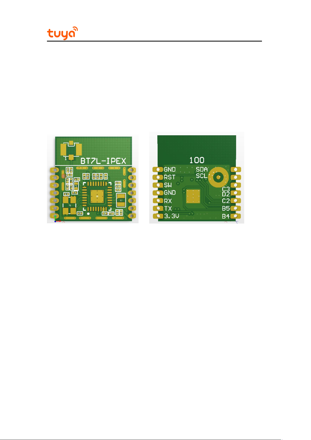
BT7L-IPEX has two rows of pins with a 2 mm pin spacing.
The BT7L-IPEX dimensions are 15mm±0.35 (W)×16.5mm±0.35 (L)×2.85mm(H). The
PCB thickness is 0.8±0.1 mm. Figure 2-1 shows the BT7L-IPEX pins.
Figure 2-1 BT7L-IPEX pins

BT7L-IPEX Datasheet
7
2.2 Interface Pin Definition
Table 2-1 BT7L-IPEX interface pins
Pin
No.
Symbol
I/O
Type
Function
1
SDC
I/O
I2C SDC,can be used as a common I/O
2
SCL
I/O
I2C SCL,can be used as a common I/O
3
C3
I/O
Common I/O, which can be used as a PWM
output of the LED drive and is connected to pin 23
on the IC
4
D2
I/O
Common I/O, which can be used as a PWM
output of the LED drive and is connected to pin 31
on the IC
5
C2
I/O
Common I/O, which can be used as a PWM
output of the LED drive and is connected to pin 22
on the IC
6
B5
I/O
Common I/O, which can be used as a PWM
output of the LED drive and is connected to pin 15
on the IC
7
B4
I/O
Common I/O, which can be used as a PWM
output of the LED drive and is connected to pin 14
on the IC
8
3.3V
P
Power supply pin (3.3 V)
9
TX
I/O
Serial interface transmission pin (UART TX),
which is connected to pin 6 on the IC
10
RX
I/O
Serial interface receiving pin (UART RX), which is
connected to pin 17 on the IC
 Loading...