

Page 1

User Manual of DS-3WF01C-2N
DS-3WF01C-2N
User Manual
Page 2

User Manual of DS-3WF01C-2N
User Manual
COPYRIGHT ©2016 Hangzhou Hikvision Digital Technology Co., Ltd.
ALL RIGHTS RESERVED.
Any and all information, including, among others, wordings, pictures, graphs are the properties of
Hangzhou Hikvision Digital Technology Co., Ltd. or its subsidiaries (hereinafter referred to be
“Hikvision”). This user manual (hereinafter referred to be “the Manual”) cannot be reproduced,
changed, translated, or distributed, partially or wholly, by any means, without the prior written
permission of Hikvision. Unless otherwise stipulated, Hikvision does not make any warranties,
guarantees or representations, express or implied, regarding to the Manual.
About this Manual
This Manual is applicable to DS-C10S-SXXT Series Video Wall Controller.
The Manual includes instructions for using and managing the product. Pictures, charts, images and all
other information hereinafter are for description and explanation only. The information contained in
the Manual is subject to change, without notice, due to firmware updates or other reasons. Please find
the latest version in the company website (http://overseas.hikvision.com/en/).
Please use this user manual under the guidance of professionals.
Trademarks Acknowledgement
and other Hikvision’s trademarks and logos are the properties of Hikvision in various
jurisdictions. Other trademarks and logos mentioned below are the properties of their respective
owners.
Legal Disclaimer
TO THE MAXIMUM EXTENT PERMITTED BY APPLICABLE LAW, THE PRODUCT DESCRIBED, WITH ITS
HARDWARE, SOFTWARE AND FIRMWARE, IS PROVIDED “AS IS”, WITH ALL FAULTS AND ERRORS, AND
HIKVISION MAKES NO WARRANTIES, EXPRESS OR IMPLIED, INCLUDING WITHOUT LIMITATION,
MERCHANTABILITY, SATISFACTORY QUALITY, FITNESS FOR A PARTICULAR PURPOSE, AND NONINFRINGEMENT OF THIRD PARTY. IN NO EVENT WILL HIKVISION, ITS DIRECTORS, OFFICERS, EMPLOYEES,
OR AGENTS BE LIABLE TO YOU FOR ANY SPECIAL, CONSEQUENTIAL, INCIDENTAL, OR INDIRECT
DAMAGES, INCLUDING, AMONG OTHERS, DAMAGES FOR LOSS OF BUSINESS PROFITS, BUSINESS
INTERRUPTION, OR LOSS OF DATA OR DOCUMENTATION, IN CONNECTION WITH THE USE OF THIS
PRODUCT, EVEN IF HIKVISION HAS BEEN ADVISED OF THE POSSIBILITY OF SUCH DAMAGES.
REGARDING TO THE PRODUCT WITH INTERNET ACCESS, THE USE OF PRODUCT SHALL BE WHOLLY AT
YOUR OWN RISKS. HIKVISION SHALL NOT TAKE ANY RESPONSIBILITES FOR ABNORMAL OPERATION,
PRIVACY LEAKAGE OR OTHER DAMAGES RESULTING FROM CYBER ATTACK, HACKER ATTACK, VIRUS
INSPECTION, OR OTHER INTERNET SECURITY RISKS; HOWEVER, HIKVISION WILL PROVIDE TIMELY
TECHNICAL SUPPORT IF REQUIRED.
SURVEILLANCE LAWS VARY BY JURISDICTION. PLEASE CHECK ALL RELEVANT LAWS IN YOUR
JURISDICTION BEFORE USING THIS PRODUCT IN ORDER TO ENSURE THAT YOUR USE CONFORMS THE
APPLICABLE LAW. HIKVISION SHALL NOT BE LIABLE IN THE EVENT THAT THIS PRODUCT IS USED WITH
ILLEGITIMATE PURPOSES.
IN THE EVENT OF ANY CONFLICTS BETWEEN THIS MANUAL AND THE APPLICABLE LAW, THE LATER
PREVAILS.
Page 3

User Manual of DS-3WF01C-2N
Regulatory Information
FCC Information
Please take attention that changes or modification not expressly approved by the party responsible for
compliance could void the user’s authority to operate the equipment.
FCC compliance: This product has been tested and found to comply with the limits for a Class B
digital device, pursuant to Part 15 of the FCC Rules. These limits are designed to provide
reasonable protection against harmful interference in a residential installation. This product
generates, uses, and can radiate radio frequency energy and, if not installed and used in
accordance with the instructions, may cause harmful interference to radio communications.
However, there is no guarantee that interference will not occur in a particular installation. If this
product does cause harmful interference to radio or television reception, which can be determined
by turning the equipment off and on, the user is encouraged to try to correct the interference by
one or more of the following measures:
—Reorient or relocate the receiving antenna.
—Increase the separation between the equipment and receiver.
—Connect the equipment into an outlet on a circuit different from that to which the receiver is
connected.
—Consult the dealer or an experienced radio/TV technician for help.
FCC Conditions
This device complies with part 15 of the FCC Rules. Operation is subject to the following two conditions:
1. This device may not cause harmful interference.
2. This device must accept any interference received, including interference that may cause undesired
operation.
EU Conformity Statement
This product and - if applicable - the supplied accessories too are marked with "CE" and
comply therefore with the applicable harmonized European standards listed under the EMC
Directive 2014/30/EU, the LVD Directive 2014/35/EU, the RoHS Directive 2011/65/EU.
2012/19/EU (WEEE directive): Products marked with this symbol cannot be disposed of as
unsorted municipal waste in the European Union. For proper recycling, return this product to
your local supplier upon the purchase of equivalent new equipment, or dispose of it at
designated collection points. For more information see: www.recyclethis.info
2006/66/EC (battery directive): This product contains a battery that cannot be disposed of as
unsorted municipal waste in the European Union. See the product documentation for
specific battery information. The battery is marked with this symbol, which may include
lettering to indicate cadmium (Cd), lead (Pb), or mercury (Hg). For proper recycling, return
the battery to your supplier or to a designated collection point. For more information see:
www.recyclethis.info
This equipment should be installed and operated with a minimum distance 20cm between the
radiator and your body
Page 4

User Manual of DS-3WF01C-2N
4
Table of Contents
Chapter 1 Product Overview .................................................................................. 5
1.1 Product Advantages ......................................................................................................5
1.2 Electrical Specifications ...............................................................................................6
1.3 Features ........................................................................................................................7
1.4 Using Example .............................................................................................................8
1.5 Hardware Overview......................................................................................................8
1.6 LED Description ..........................................................................................................9
Chapter 2 Installation............................................................................................... 11
2.1 Connections and installation ....................................................................................... 11
2.2 Restore to Factory Settings ......................................................................................... 12
2.3 Default Values ............................................................................................................ 12
Chapter 3 Quick Configuration ............................................................................ 13
3.1 Log in ........................................................................................................................ 13
3.2 Wizard ....................................................................................................................... 16
Chapter 4 Status ...................................................................................................... 19
Chapter 5 System .................................................................................................... 21
5.1 System ....................................................................................................................... 21
5.2 Administration ........................................................................................................... 24
5.3 LED Configuration ..................................................................................................... 25
5.4 Backup / Upgrade ....................................................................................................... 26
5.5 Reboot ....................................................................................................................... 27
Chapter 6 Services .................................................................................................. 28
6.1 CAPWAP ................................................................................................................... 28
6.2 SNMP ........................................................................................................................ 29
Chapter 7 Network ................................................................................................. 33
7.1 Interfaces ................................................................................................................... 33
7.1.1 Common Configuration ............................................................................... 33
7.1.2 DHCP Server ................................................................................................ 36
7.1.3 Add New Interface ....................................................................................... 37
7.1.4 Router Mode ................................................................................................. 39
7.2 Wifi ............................................................................................................................ 42
7.2.1 Device Configuration ................................................................................... 42
7.2.2 Interface Configuration ................................................................................ 50
7.3 Firewall ...................................................................................................................... 52
7.4 VLAN ........................................................................................................................ 54
7.5 Ping Watchdog ........................................................................................................... 57
Chapter 8 Logout .................................................................................................... 59
Chapter 9 FAQ ........................................................................................................ 59
Page 5

User Manual of DS-3WF01C-2N
5
Chapter 1 Product Overview
1.1 Product Advantages
DS-3WF01C-2N is specially designed for elevator wireless video transmission and
customized products; compared with the traditional elevator video transmission
products, it has the following advantages:
1. Good anti - jamming ability
Super low frequency power supply interference, electrical spark interference, inverter
motor interference, control signal interference etc. that below tens of kilohertz are
found in the elevator environment, the use of WIFI high-frequency transmission, can
effectively avoid the interference of elevator environment. At the same time the device
supports extended frequency, can avoid the same frequency interference in the
traditional WIFI.
2. Short construction period
In the absence of a large amount of wiring work, so greatly shorten the construction
period, save a lot of human resources.
3. Embedded XTrans technology
DS-3WF01C-2N devices is embedded with XTrans technology, including TDMA,
20M/40MHz bandwidth, intelligent rate control, Auto ACK Time-out adjust. It makes the
device have longer transmission distance, higher throughput and better point-to-multipoint performance.
4. Embedded hardware watchdog
DS-3WF01C-2N is embedded with hardware watchdog, which is used to monitor the
working status of the device. Once the system is not working properly, the device can be
rebooted to guarantee the stability of the system.
5. More Non-standard channels availability
Currently most of the WIFI devices are working at standard 802.11 2.4GHz frequency.
However, standard 802.11 2.4GHz only provide limited channels, and there is serious
interference if there are a lot of 2.4GHz WIFI devices nearby. DS-3WF01C-2N support
more channels near 2.4GHz band, and spread the band to non-standard frequency part.
The advantage of working at the non-standard band is to avoid the interference in the
standard channels, and the wireless throughput can be improved.
Page 6

User Manual of DS-3WF01C-2N
6
Antenna
Internal, 6dBi, H: 65° V: 60°
Temperature
Humidity
Dimensions:
150*150*31.6mm
Encryption
WPA
-
PSK/WPA2
-
PSK
Network
Router/Bridge
Security
MAC filter
,
SSID hidden
Note: Please confirm whether those non-standard channels are permitted locally before
using them.
1.2 Electrical Specifications
DS-3WF01C-2N electrical specifications as shown below:
Table 1-1 Electrical Specifications
Items Specifications
Standard
Operation
Frequency
Wireless
Receive Sensitivity
Operation
Frequency
IEEE802.11 b/g/n(2T2R 300Mbps)
802.11 b/g/n(HT20): 2412MHz~2462MHz
802.11 n(HT40): 2422MHz~2452MHz
-72dBm@65Mbps, -97dBm@1Mbps
11n:300Mbps(HT40),130(HT20)
11g:54Mbps
Power supply 48V POE+ or 12V DC
Interface
Hardware
Operation
Temperature
Storage
Operation
3×10/100M Base-TX (Cat. 5/5E, RJ-45) ports
-30℃~+65℃
-40℃~+85℃
5%~95%RH
Application
scenarios
Software
Network Protocol TCP/UDP/ARP/ICMP/DHCP/HTTP/NTP
TDMA
Elevator Car / Elevator Room
Supported (Avoid 802.11 hidden-node problems, and
improve the point-to-multi-point performance)
Page 7

User Manual of DS-3WF01C-2N
7
Firmware Update
Supported
supported
Auto ACK timing
Adjust
Management and
Logs
Web based
Configuration
Bandwidth
Supported
NTP, SNMP, Syslog, Telnet, AC
Supported
20M/40MHz
1.3 Features
• High performance 802.11n 2×2 MIMO chip
• It supports four operating modes: Access Point, Client, Access Point (WDS), Client
(WDS)
• Integrated XTrans technology, including TDMA, intelligent rate control, Auto ACK
Time-out adjust
• TDMA solves the problems of hidden-node problem in the 802.11 network, thus
having better long-distance and PTMP performance
• Support point-to-point, point-to-multipoint connection
• Unique antenna, RF amplifier, and low noise receiver to ensure long-distance video
transmission
• Web based working scenario selection makes the installation and setting much
easier
• Multi-network interface design, more conducive to the expansion of a variety of
applications
• Web-based configuration, easy to use
• High temperature flame retardant housing ensure stable operation in harsh
Page 8

User Manual of DS-
3WF01C
Using Example
2N products can be used ins
transmission, while the use of multiple network interfaces equipped with elevator
advertising machine to real
properties or assembling outdoor wireless dev
Hardware Overview
Hardware information of DS
8
ide the elevator shaft to survey the video
time updates. Backhaul data networks can rely on existing
2N is described in the following Table:
-2N
environments
1.4
DS-3WF01C-
-
ice.
1.5
CPU/Baseband Radio
Figure 1-1 DS-3WF01C-2N Using Example
-3WF01C-
Table 1-2 Hardware Information
Hardware Specifications
Atheros QCA9531
Page 9
User Manual of DS-3WF01C-2N
9
Memory 64MB DRAM, 8MB Flash
Physical Interface 3×10/100M Base-TX (Cat. 5/5E, RJ-45) Ports
LED LAN, WLAN, 3×Link Quality
Power Supply POE+, Power Adapter 12V
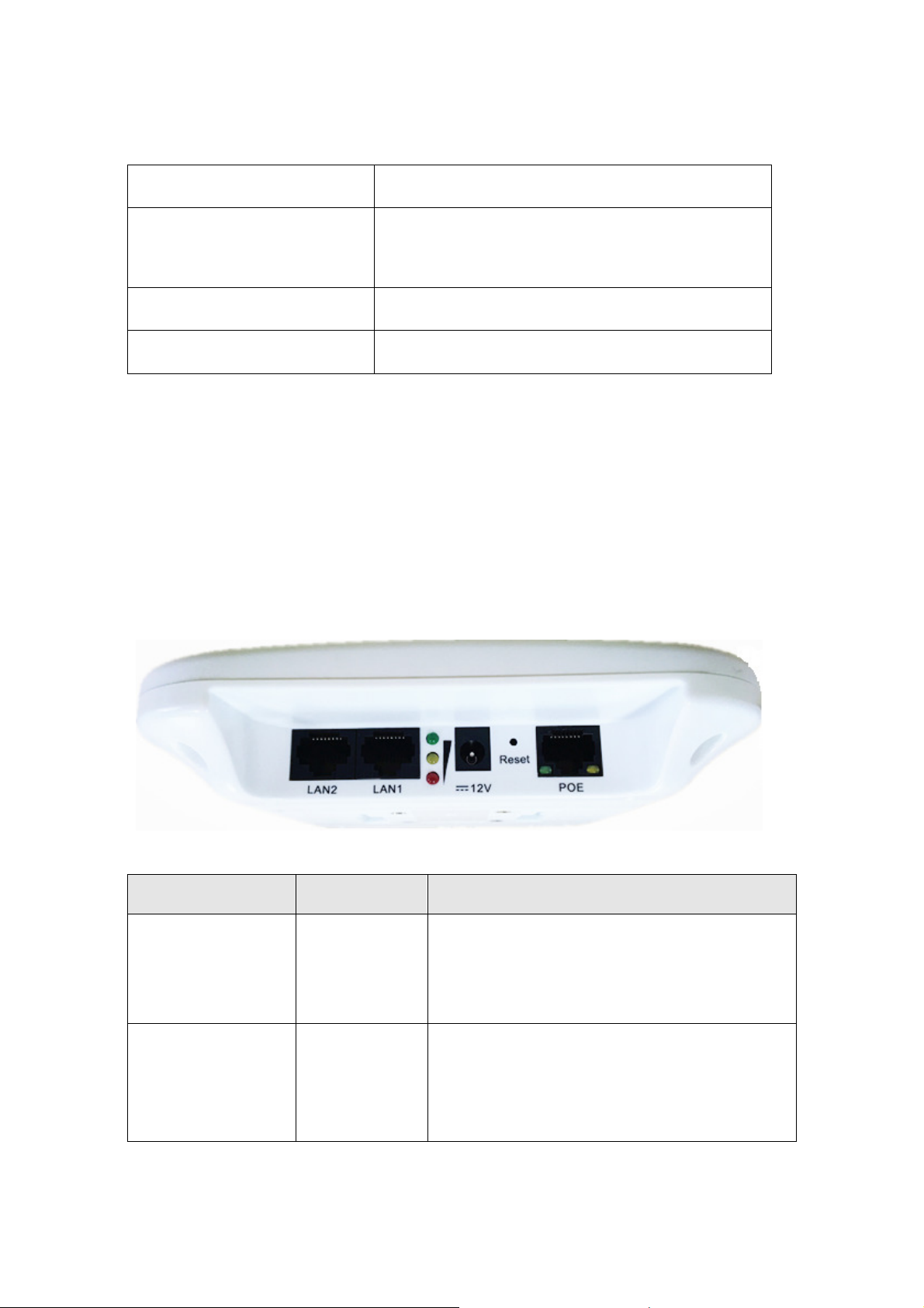
1.6
LED Description
DS-3WF01C-2N use LED to reflect the current status of working and quality of the
connection. LED is mainly divided into two parts, status of the device and the quality of
the connection. As shown on the picture, the first left LED indicator for the LAN, the
second from the left for the WLAN indicator light, the middle three signal strength
indicator, as specified in the following Table:
Figure 1-2 LED
Table 1-3 LED Information
LED Color Status
LAN Yellow The light indicates there is an external
device connects to the LAN port which is the
LAN1 port of DS-3WF01C-2N.
WLAN Green The light indicates that the wireless DS-
3WF01C-2N is enabled.
Blinking means enabled wireless devices,
Page 10

User Manual of DS-3WF01C-2N
10
and is sending the wireless data.
Page 11
User Manual of DS-3WF01C-2N
11
Red The light indicates the signal level
Yellow
Green
Signal Level
Green, yellow and red lights on, indicates
the wireless signal level is high
Yellow and red lights on, indicating signal
level is medium
Only red light on, indicating that the signal
is weak or no signal
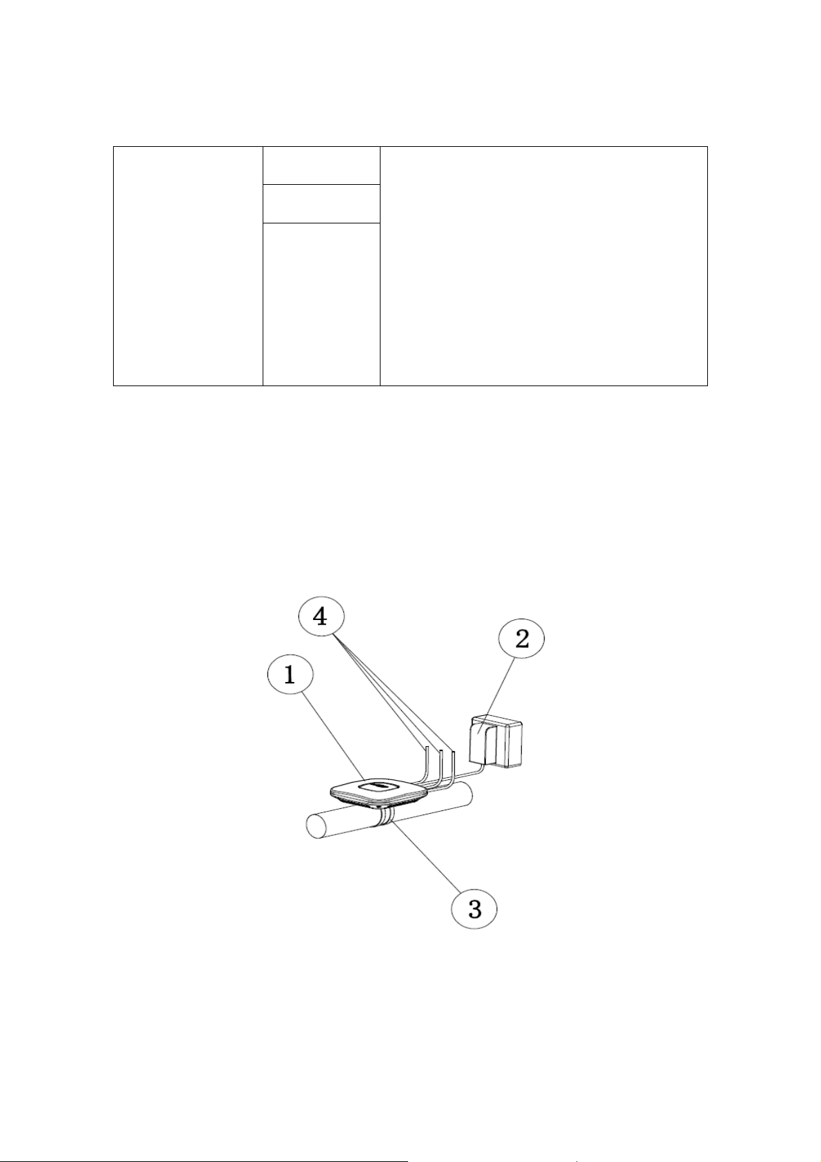
Chapter 2 Installation
2.1
The installation of DS-3WF01C-2N as shown in the following figure:
Connections and installation
1.
DS-3WF01C-2N Device
Figure 2-1 Connections
Page 12
User Manual of DS-3WF01C-2N
12
2.
POE power adaptor
3.
Mount Bracke
4.
Three LAN port on the device can be connected to the camera
There are two devices within a package: DS-3WF01C-2N (T) and DS-3WF01C-2N (R), two
POE power adaptors. The DS-3WF01C-2N (T) should be mounted on top of the elevator
car; it’s normally linked up with network cameras and other network advertising screens
equipment through the network cable. DS-3WF01C-2N (R) should be installed in the
elevator room, for receiving the network signal. The two devices can be fixed by each
hoop.
The LAN port of the POE adaptor can be used for connecting a camera. You can also use
your own DC12V power supply for the device.
t
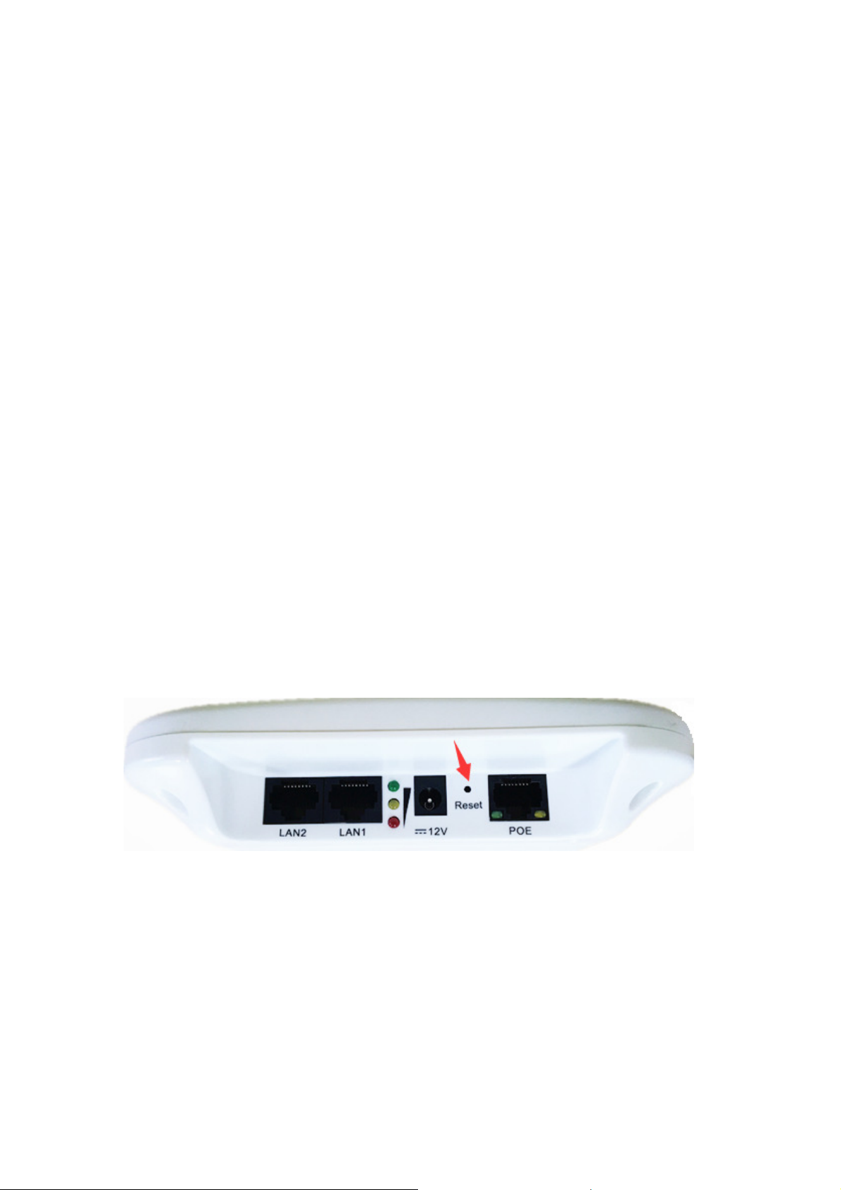
2.2
In some cases, users can restore the device to factory settings. Push the reset button for
5~10 seconds and wait for 2~3 minutes. The device will restore to factory settings.
2.3
Restore to Factory Settings
Figure 2-2 Reset
Default Values
There are two DS-3WF01C-2N devices: DS-3WF01C-2N (T) and DS-3WF01C-2N (R), a
twin pack. They can be used directly without debugging after installation, the main
Page 13

User Manual of DS-3WF01C-2N
13
parameters of the default factory settings as shown below. If you want to change the
default values and other parameters, please read the manual in the following sections.
Table 2-1 Main parameters at the factory settings
Items Elevator Car / DS-3WF01C-
2N(T)
Wireless
mode
IP address 192.168.1.35 192.168.1.36
User name root root
Password admin admin
SSID Wireless-Bridge Wireless-Bridge
Hidden SSID Enable N/A
Channel 6(2.437 GHz) Auto
Encryption WPA2-PSK Key:
Access Point Client
1234567890abc
Elevator Room / DS-3WF01C-
WPA2-PSK Key:
1234567890abc
2N(R)
Network
mode
Bridge Bridge
Chapter 3 Quick Configuration
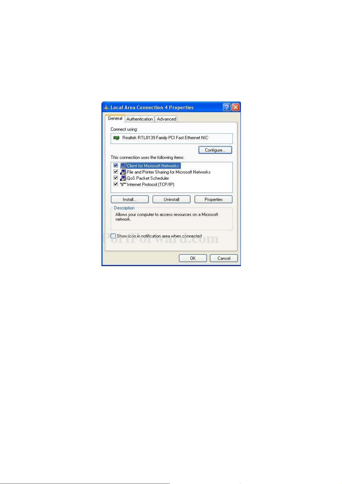
3.1 Log in
To log in the DS-3WF01C-2N device, you need to configure the TCP/IP of your computer
first as the following steps:
Page 14
User Manual of DS-3WF01C-2N
14
1. Right click Local Area Connection icon of your computer and click properties, then
click Continue, the Local Area Connection Properties dialog box appears as shown
below:
Figure 3-1 Local Area Connection Properties
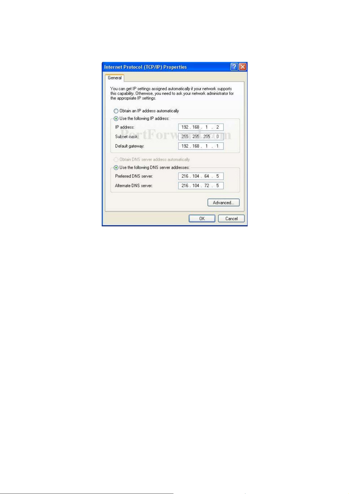
2.
Select Internet Protocol (TCP/IP) and click Properties button, and the following
dialog box appears:
Page 15
User Manual of DS-3WF01C-2N
15
Figure 3-2 IP Settings
3. As shown in the figure above, IP address should be set to 192.168.1.*, but cannot
be the same as DS-3WF01C-2N, here * can be a number between 1-255 (but not 36
or 35) since the DS-3WF01C-2N (T) default IP address is 192.168.1.35, and the DS-
3WF01C-2N(R) default IP address is 192.168.1.36.
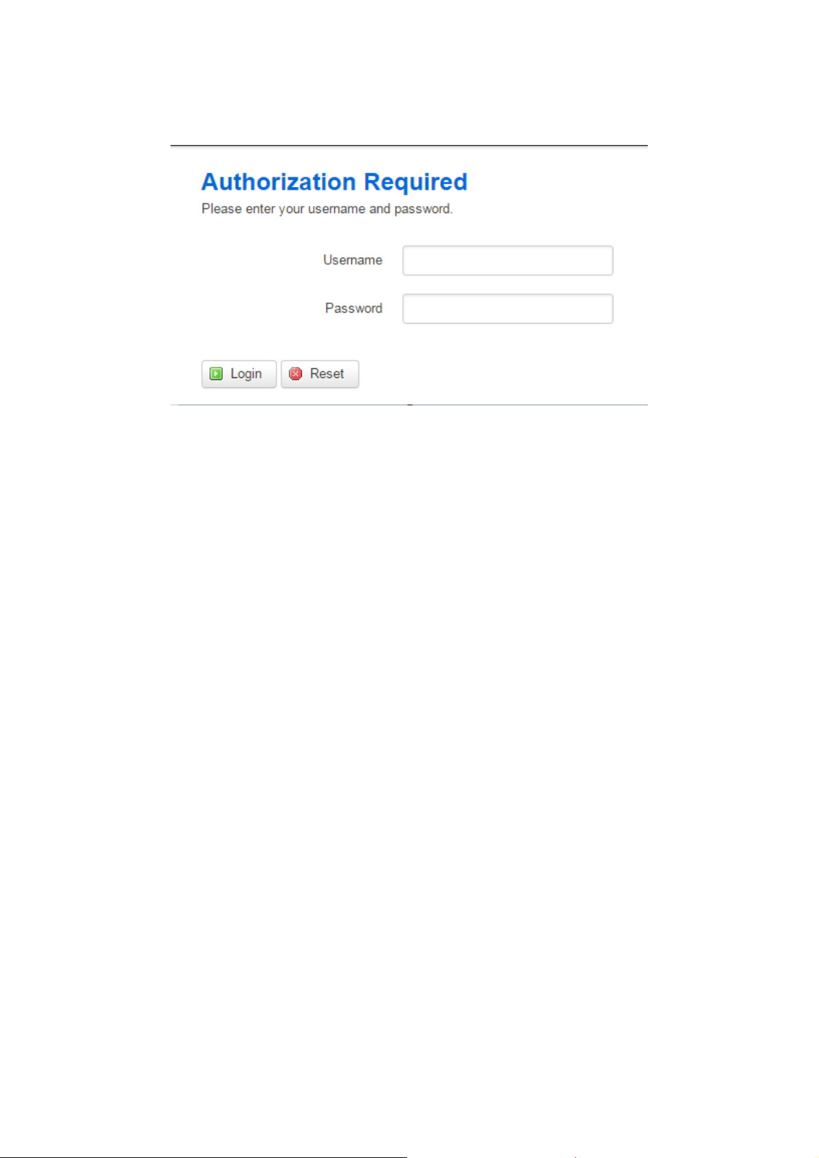
4. Input the default IP 192.168.1.36 or 192.168.1.35 into the address bar of your web
browser, click Enter.
5. Input the user name and password (default is root/admin), the you can log in to the
web configuration menu of the DS-3WF01C-2N device
Page 16
User Manual of DS-3WF01C-2N
16
Figure 3-3 DS-3WF01C-2N Login Page
3.2
Wizard
Users can quickly configure DS-3WF01C-2N according to the following steps through the
wizard in this chapter.
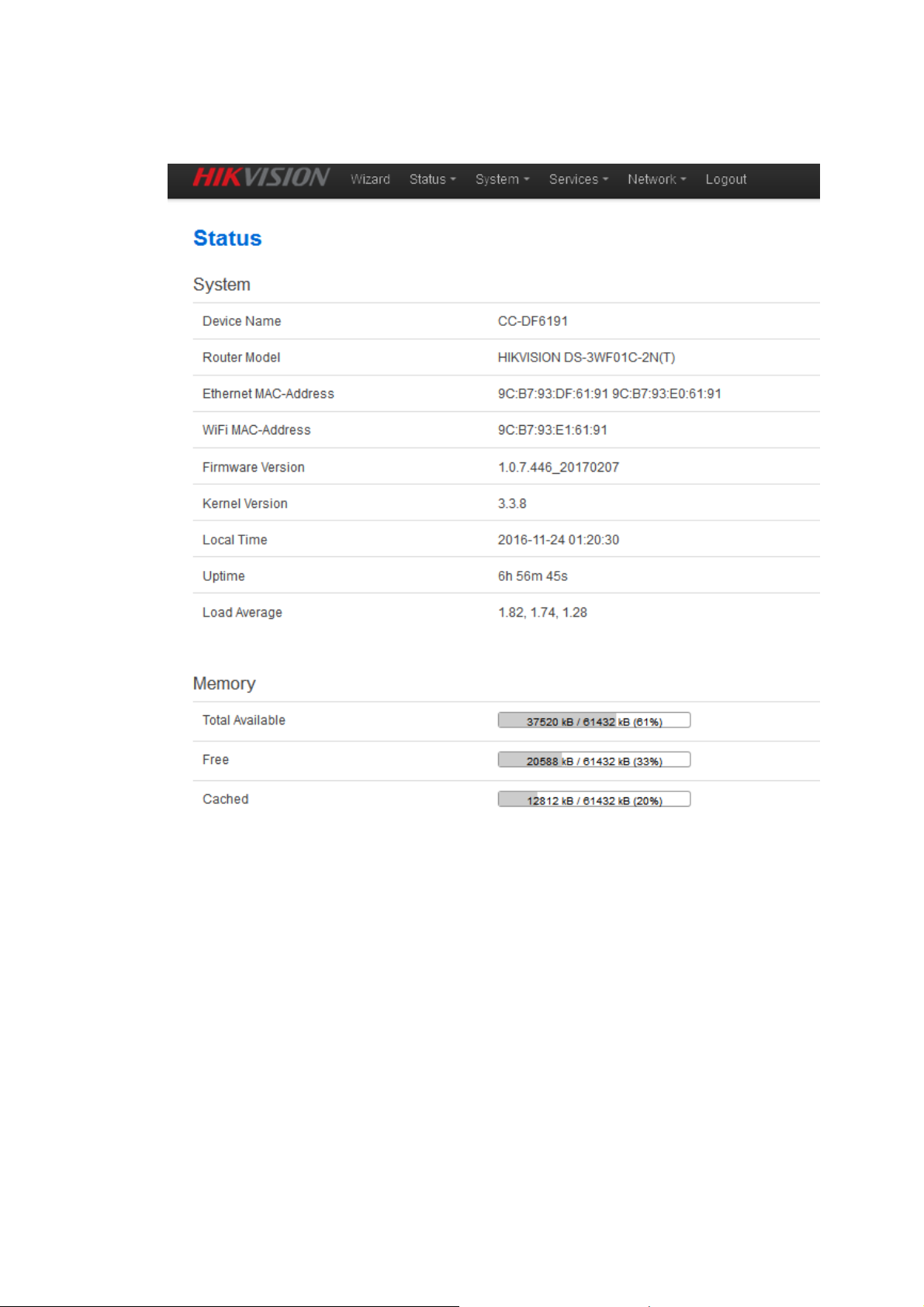
1. The first page shown after log in is the Status page, which indicates the working
status, current setting, software version and other information of the DS-3WF01C-
2N device. User can switch to other pages by clicking the main menus.
Page 17
User Manual of DS-3WF01C-2N
17
Figure 3-4 Status– DS-3WF01C-2N (T)
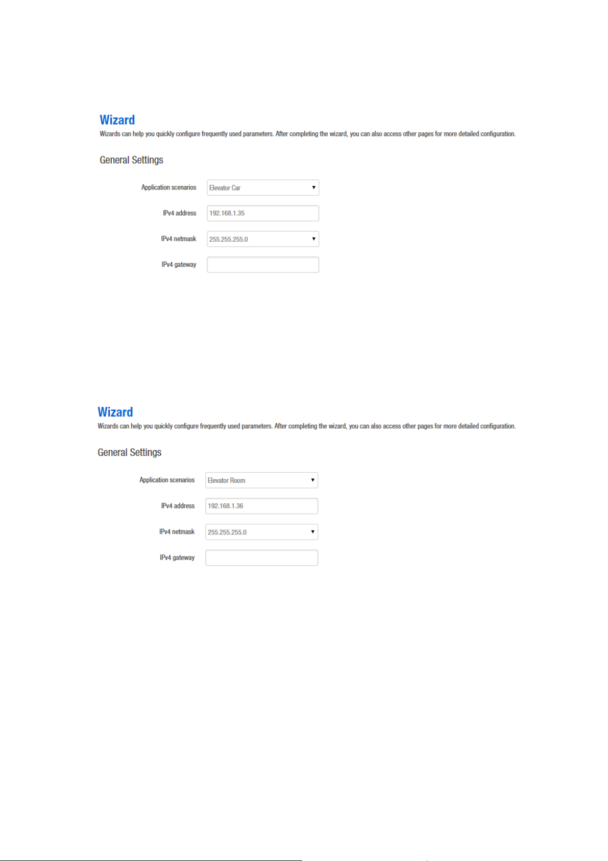
2. Click Wizard. The page goes to Wizard page as shown below, and this page helps to
set the basic network parameters. The default mode is Bridge mode, and the
default LAN IP address of DS-3WF01C-2N (T) is 192.168.1.35, the default LAN IP
address of DS-3WF01C-2N(R) is 192.168.1.36. If the user wants to configure the
device to Router mode, please refer to chapter 7.
Note: If there are several DS-3WF01C-2N devices connected in the Point-to-Point or
Point-to-Multi-Point topologies, they must be configured to different IP address to avoid
conflicts.
Page 18
User Manual of DS-3WF01C-2N
18
Figure 3-5Wizard – DS-3WF01C-2N (T)
Elevator Car: (AP mode), in this scenario mode, DS-3WF01C-2N will be set to AP mode;
it can be connected to a client device. When you close the TDMA function, your phone
or laptop can connect to the DS-3WF01C-2N. If you need other wireless configurations
in detail, please refer to chapter 7.
Figure 3-6 Wizard – DS-3WF01C-2N (R)
Elevator Room: In this scenario mode, DS-3WF01C-2N will be set to client mode; it can
be connected to an access point device.
Notes: The default SSID of DS-3WF01C-2N (T) and DS-3WF01C-2N (R) is Wireless-Bridge,
and they can be directly interconnected and transmit audio and video or data, if there
are other DS-3WF01C-2N equipment within 500 meters, you should change SSID to
different one in order to avoid connection confusion, please refer to chapter 7 to see
how to modify the SSID.
Page 19

User Manual of DS-3WF01C-2N
19
3、Click Save & Apply button, the device will reboot and apply your configuration.
Figure 3-7 Complete wizard settings
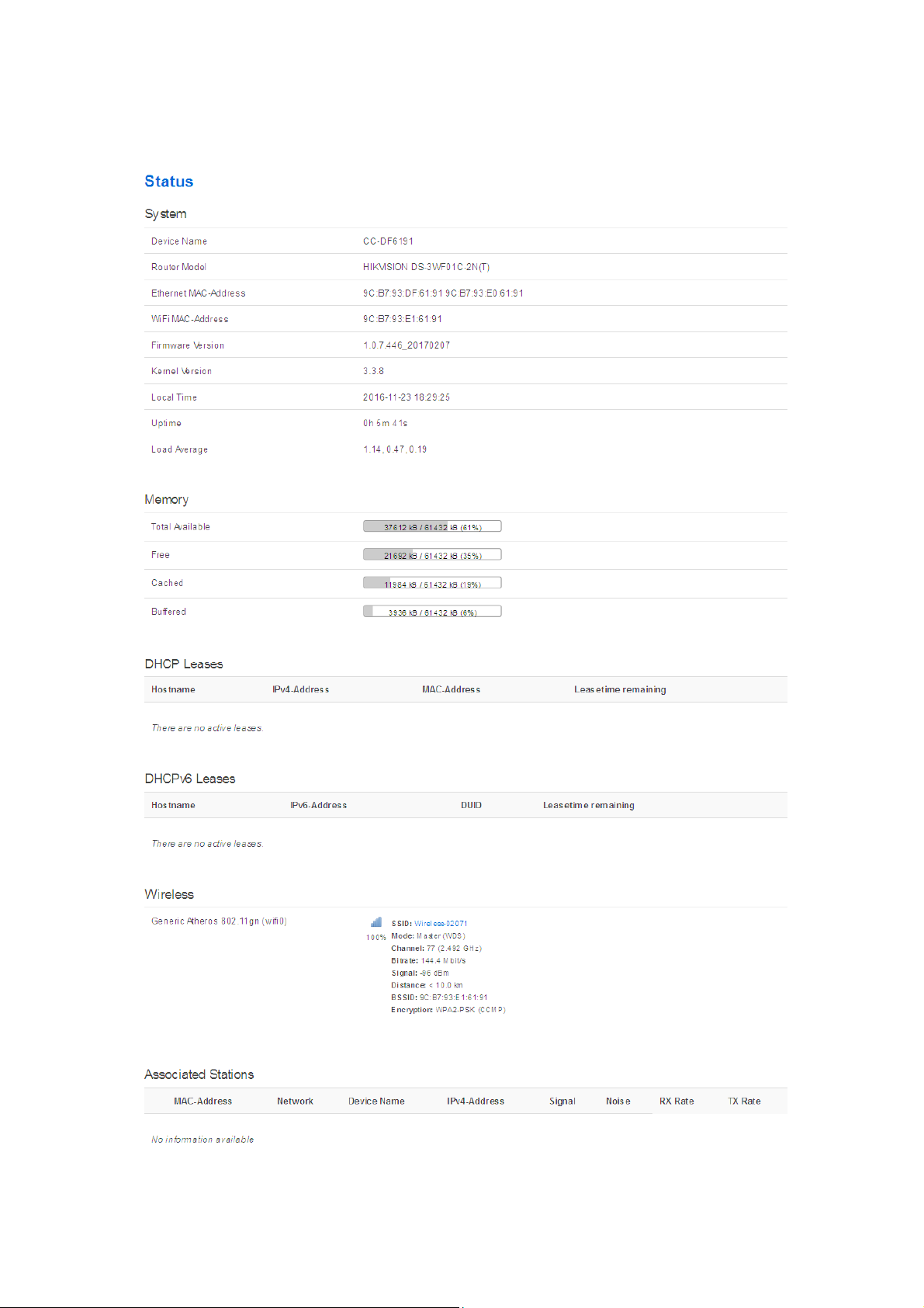
Chapter 4 Status
The status page is the first page after logging in, the page displays the current
configuration and working status of the device. It is the first item in the menu bar, as
shown in figure:
Page 20
User Manual of DS-3WF01C-2N
20
Page 21

User Manual of DS-3WF01C-2N
21
Figure 4-1 Status
Overview: Status->Overview, This page shows the current configuration information of
the system, including the system, memory, network, DHCP leases, wireless, associated
stations, active UPnP redirects.
Firewall: Status - > firewall, showing the device's current IPv4 and IPv6 firewall; please
do not click on the "Reset Counters" and "Restart Firewall" without the guidance
of network manager, so as to avoid unnecessary trouble.
Routes: Status - > Routes, this page display the active routes on the system.
System log: displaying the system log information of the device.
Kernel log: displaying the kernel log information of the device.
Processes: displaying the device system current process and its status information;
please do not click "Hang Up", "Terminate", "Kill" without the guidance of network
manager, so as to avoid unnecessary trouble.
Real time Graphs: display the real-time load, traffic, and link information of the device.
Chapter 5 System
System page includes: System, Administration, Software, Startup, Scheduled Tasks, LED
Configuration, Backup / Flash Firmware and Reboot sub-pages. The following are
descriptions of the system, Administration, backup / upgrade and reboot sub-pages.
5.1 System
Here you can configure the basic aspects of your device like its hostname or the time
zone.
Page 22

User Manual of DS-3WF01C-2N
22
General Settings: some basic information is supported to configure on this page,
including time, log, language and interface style.
Click on the "general settings" page, click on "Sync with browser" to synchronize the
local time to the device, and it will be displayed in the status page too. The time
synchronization can help network administrator check equipment operation status and
log information conveniently, and can also help tracking running status of the device.
Host name is corresponding to the Router Name of the status page; users can change it
according to their own needs as shown in the figure.
Figure 5-1 System Properties – General Settings
Logging:
When Syslog is enabled, and the System Log server’s IP is also set here, the log
information will be output to the Syslog server automatically.
Page 23

User Manual of DS-3WF01C-2N
23
Language and Style:
Figure 5-2 System Properties - Logging
choose the language of the web page you want. You can modify
the Language into English or Chinese. The default Design is bootstrap style, you can also
choose openwrt style based on personal hobby.
Figure 5-3 System Properties – Language and Style
Time Synchronization:
when the device can surf the Internet, you can enable the NTP
client and fill in the NTP server candidates. DS-3WF01C-2N will get time automatically
from the NTP server and displayed in the status page. At this point you can also tick the
Provide NTP server and make the device as a NTP server for other devices connected to
the DS-3WF01C-2N to acquire time.
Page 24

User Manual of DS-3WF01C-2N
24
Figure 5-4 System Properties – Time Synchronization
5.2
Administration
Router Password: Changes the administrator password for accessing the device.
Figure 5-5 Password
SSH Access: Drop bear offers SSH2 network shell access and an integrated SCP server.
Here you can change the default SSH parameters.
Page 25

User Manual of DS-3WF01C-2N
25
Figure 5-6 SSH
Note: after saving the configuration of administration page, the device will
automatically close telnet access, the user can login the device through more secure SSH.
System->Software, Startup and Scheduled Tasks pages: it is not recommended to
operating, just keep the default configuration.
5.3
LED Configuration
Click on System->LED Configuration, in this page you can customize the behavior of the
device LEDs if possible; it defines the value of the signal strength required for the light of
the 3 LEDs, which works only on the client mode device.
Page 26

User Manual of DS-3WF01C-2N
26
Figure 5-7 LED Settings
The red LED intensity value is the smallest of the 3 LEDs (red < yellow < green), the
default range of red LED: -95~-1dBm, yellow: -71~-1dBm, green: -56~-1dBm. When the
signal strength is higher than -95dB and below -71dBm, red light; when the signal
strength is higher than -71dB and below -56dBm, both red and yellow light; when the
signal strength is higher than -56dBm, all the 3 LEDs light.
5.4
Backup / Upgrade
System->Backup / Flash Firmware page is very simple to use. It is divided into the
following 2 parts:
Backup / Restore
Click "Generate archive" to download a tar archive of the current configuration files.
Click "Perform reset" to reset the firmware to its initial state.
To restore configuration files, you can upload a previously generated backup archive.
Page 27

User Manual of DS-3WF01C-2N
27
Figure 5-8 Backup / Restore
Flash new firmware image
Upload a sysupgrade - compatible image here to replace the running firmware. Check
"Keep settings" to retain the current configuration (requires an OpenWrt compatible
firmware image).
Figure 5-9 Flash new firmware image
5.5
Reboot
Click Perform reboot to reboot the operating system of your device.
Figure 5-10 Reboot
Page 28

User Manual of DS-3WF01C-2N
28
Chapter 6 Services
Services page is divided into dynamic DNS, SNMP, CAPWAP, WiFiDog and UPNP, the
following lists only CAPWAP and SNMP instructions.
6.1
CAPWAP:
CAPWAP settings page as shown in figure. Enable this feature; you need to use the AC
management system.
Interface:
to their own interface configuration.
CAPWAP
Control and Provisioning of Wireless Access Points Protocol Specification.
Figure 6-1 CAPWAP
the default option is LAN, the network administrator can choose it according
Location:
your needs.
Discovery mode:
Auto, AC IP can be automatically discovered by the device; when you choose manual,
you need to fill in AC IP address. After CAPWAP feature is enabled, click on the save &
application button, the device will apply AC configuration and restart, then the device
will join the AC.
the location of the device on the AC, it can be modified in the AC according to
choosing how to find the IP address of AC. When you choose
Page 29

User Manual of DS-3WF01C-2N
29
Note:
If you want to set a client mode device to join AC successfully, the client should be
connected to the access point device first, and the access point device has also opened
the CAPWAP function and joined the same AC system.
6.2
Figure 6-2 CAPWAP Settings
SNMP
SNMP: When SNMP is enabled, you can check the working condition and information
of the device by a SNMP tool.
Page 30

User Manual of DS-3WF01C-2N
30
Figure 6-3 SNMP
You can configure the SNMP parameters in Basic Settings part. Check SNMP Enable and
fill in Location, Mail, Group; then you can manage the device through a SNMP tool in
your computer.
Page 31

User Manual of DS-3WF01C-2N
31
Figure 6-4 Basic Settings
The device supports a higher level of SNMP protocol; you can choose to enable SNMPv3,
with the corresponding SNMP management tools to use.
Page 32

User Manual of DS-3WF01C-2N
32
Figure 6-5 SNMPv3 Settings
The device also supports trigger trap information; you can choose to enable Trap, fill in
the trap server IP, then you will receive Trap information through the SNMP
management tool in your computer.
Figure 6-6 Trap Settings
Page 33

User Manual of DS-3WF01C-2N
33
Chapter 7 Network
The network settings page is divided into the Interface, Wifi, DHCP and DNS, Hostnames,
Static Routes, Diagnostics, Firewall, VLAN, Ping Watchdog, QoS. We will focus on the
Interface, wireless, network diagnostics, firewall, Ping, Watchdog. VLAN.
The following will focus on the introduction of the Interface, Wifi, Diagnostics, Firewall,
VLAN, Ping Watchdog.
7.1
Interfaces
7.1.1 Common Configuration
Open the network interface page; you’ll see the overview of the current interface.
Figure 7-1 Interfaces
Click “Edit” button, you will enter the Interfaces-LAN page. On this page you can
configure the network interfaces. You can bridge several interfaces by ticking the
"bridge interfaces" field and enter the names of several network interfaces separated by
spaces. You can also use VLAN notation INTERFACE.VLANNR (e.g.: eth0.1).
Page 34

User Manual of DS-3WF01C-2N
34
Protocol:
Figure 7-2 General Setup
the interface access IP address options, it divided into static address, DHCP
client (to obtain the IP dynamically) and a variety of other ways. If you set a static IP, you
need to set the IP, subnet mask, etc.; when set to DHCP client, the device can obtain IP
from DHCP server automatically.
Page 35

User Manual of DS-3WF01C-2N
35
IPv4 address:
IP address of this interface, you can configure it according to your own
needs, but to ensure that IP cannot be the same as other devices in the same network,
so as not to cause IP address conflict.
IPv4 netmask:
the subnet mask of this interface, you can set it according to your own
needs.
Use custom DNS server: It should be set to the value of the local DNS server.
Click on Physical settings of the “Interface – LAN” page, you can modify the current
interface configuration which contains the wired interface and wireless interface.
Bridge interfaces:
Figure 7-3 Physical Settings
creates a bridge over specified interface(s). unchecking the Bridge
interfaces and you could only choose one interface.
Enable STP:
Interface:
Enables the Spanning Tree Protocol on this bridge
Ethernet adapter "eth0” corresponds to the POE power supply LAN port of
the device, Ethernet adapter “eth1" corresponds to the other two LAN port of the
device.
Page 36

User Manual of DS-3WF01C-2N
36
Click to enter the firewall settings page. Choose the firewall zone you want to assign to
this interface. Select unspecified to remove the interface from the associated zone or fill
out the create field to define a new zone and attach the interface to it. please refer to
the Manual Section 7.3 firewall.
Figure 7-4 Firewall Settings
7.1.2 DHCP Server
Drop down the interface page; you can see the basic settings of the DHCP server.
Page 37

User Manual of DS-3WF01C-2N
37
DHCP:
Figure 7-5 DHCP Server
Assign IP address to client device, such as phones, laptops etc. A device should
enable DHCP client mode to get IP automatically.
7.1.3 Add New Interface
Click on the “Add new interface” button to add a new interface.
Figure 7-6 Add new interface
Page 38

User Manual of DS-3WF01C-2N
38
Fill in the name of the new interface, such as LAN2, select the Ethernet adapter eth1
interface, all of the configuration in this page can be modified again in the subsequent
pages.
Figure 7-7 Create Interface
Click Submit, will enter the new LAN2 interface configuration page. This page can be
configured for all the existing interfaces, as shown below; you can still see the original
LAN interface.
Page 39

User Manual of DS-3WF01C-2N
39
Figure 7-8 Create LAN2 interface
Please refer to chapter 7.1.1 to see how to configure the interface.
7.1.4 Router Mode
Routing mode DS-3WF01C-2N is equivalent to a router, it has a WAN port and LAN port.
You should select an interface which needs to be removed from the default LAN
interface for the WAN interface configuration.
Below we will set eth1 port to WAN as an example, introduces the configuration of the
WAN. Please refer to the manual 7.1.1 Ethernet adapter "eth1" removed from the LAN
interface.
Page 40

User Manual of DS-3WF01C-2N
40
Figure 7-9 Router Interface – WAN Settings
Click the "Add new interface" of the Interfaces page, and fill in the name of the new
interface, such as ETH1, you can choose a static address for the new interface protocol,
all of the current page configuration can be modified in the subsequent page.
Figure 7-10 Router-Interface
Page 41

User Manual of DS-3WF01C-2N
41
Click "submit". Into the newly created interface configuration page, fill in the IPv4
address which should be different with LAN segments, such as 192.168.2.35.
Figure 7-11 Router Interface – General Setup
IPv4 gateway: In general, the IPv4 gateway address and WAN IP address are in the same
network.
In general setup - the firewall settings page, select the default wan firewall-zone, after
saving the application, you will see ETH1 is set to the WAN zone, then routing mode
setup is complete, eth1 port is set for the WAN port. Firewall rules modify please refer
to the chapter 7.3 firewall chapters.
Page 42

User Manual of DS-3WF01C-2N
42
Figure 7-12 Router Interface - Firewall Settings
7.2
Wifi
7.2.1 Device Configuration
The Device Configuration section covers physical settings of the radio hardware such as
channel, transmit power or antenna selection which is shared among all defined
wireless networks (if the radio hardware is multi-SSID capable).
Open the Network -> Wifi page, you will see the current wireless profile and the
information of associated stations.
Figure 7-13 Wireless Overview
The device can scan the SSID nearby; you can connect to the corresponding wireless
network according to your needs.
Page 43

User Manual of DS-3WF01C-2N
43
Figure 7-14 Scanning SSID
Click the SSID you need, here we select the “office-2.4G TB2I” as an example. Click on "
Join Network”, it will appear the following tips as shown below, and if you check
"Replace the wireless configuration", click on the confirmation will cover all current
wireless template settings, please choose carefully.
Figure 7-15 Join Network-1
Here we uncheck the "Replace wireless configuration", click "Submit", it will appear the
following page below.
Page 44

User Manual of DS-3WF01C-2N
44
Figure 7-16 Join Network – 2
Click “Save & Apply”, wait a moment, and then Turn to Network->Wifi page, you will see
the “office-2.4G TB2I” on the Associated Stations list.
Page 45

User Manual of DS-3WF01C-2N
45
Figure 7-17 Join Network - 3
When the device has been added 8 wireless profiles, or there is a client mode wireless
profile in the 8 profiles, click on Join Network will appear as follows.
Figure 7-18 Join Network - 4
Click the Add button to add more wireless profiles, the device can add up to eight
wireless profiles, and the device can only have one client mode profile, you can choose
to enable or disable the added wireless profiles.
Page 46

User Manual of DS-3WF01C-2N
46
Figure 7-19 Add Wireless Profile
Click the Edit button; you can enter the wireless configuration page. The basic settings
page as shown below.
Page 47

User Manual of DS-3WF01C-2N
47
Channel:
Figure 7-20 General Setup
The channel can be modified when the device is configured to Access Point
mode or WDS Access Point mode. The device can only work on one channel at the same
time.
Transmit Power:
The device output power. When the output power is increased, the
signal distance and signal strength will be improved.
Mode:
You can keep the default 802.11g+n mode to guarantee optimal transmission
rate.
Page 48

User Manual of DS-3WF01C-2N
48
HT Mode:
Channel width selection, the device supports 20/40+/40-MHz bandwidth. In
general, the wider the bandwidth is, the greater the data throughput rate.
Max Transmission Rate:
it can be used to limit the max transmission rate of a device.
Click on Device Configuration->Advanced Settings, you can configure the advanced
settings of the device in this section.
Country Code:
Figure 7-21 Advanced Settings
Different countries allows different channels, you can choose the
country code to allow the device works at the channels only permitted in the particular
country. When you set Compliance Test mode, the frequency will extend to 23122732MHz.
Aggregation:
It enables several data frames of 802.11 to be aggregated and transmitted
out, thus improve the throughput. The larger the set value, the higher the throughput.
Page 49

User Manual of DS-3WF01C-2N
49
VAP Isolation: The device supports multiple VAP; if this feature is enabled, and when
the client1 is connected to VAP1, the client1 will not be able to communicate the client2
which is connected to VAP2.
TDMA::::
Currently, most of the outdoor bridge products are developed based on 802.11
protocols, however, it has the limitations of short-distance, hidden node problems, and
poor point-to-multi-point performance.
XTrans technologies developed and patented by HIKVISION, utilizing a series of
advanced technologies such as TDMA, intelligent rate control, Auto ACK Time-out Adjust,
having the advantage of long transmission range, high date rate and robust transmission.
XTrans technology solves the problems of hidden-node problem in the 802.11 network
infra-structure. Intelligent rate control algorithm can be adapted to quick channel
quality variations, while stabilize the wireless throughput, thus suitable for long-distance
transmission. ACK Time-out Auto Adjust can automatically detect the distances of the
devices, and adjust the wireless parameters to achieve the best link quality.
To use the TDMA, the user needs to enable TDMA mode in the AP device, and set a
priority level in the station device. When several stations are connected to one AP,
different clients demand different throughput. If the client demands higher throughput,
its priority level can be set to High, otherwise set to Low. When the client demands the
same throughput, their priority level can be set to the same level.
Note: When using TDMA mode, the TDMA button need to be enabled at AP devices in
the web-based configuration menu. The devices from other vendors cannot be
connected to DS-3WF01C-2N in the TDMA mode. When TDMA is enabled, your phone
or laptop cannot be able to connect to the device.
Auto ACK-Timeout Adjust:It is suggested to enable this function, so that the distance
between 2 devices can be detected and all the related parameters can be optimized to
achieve the best link quality.
Page 50

User Manual of DS-3WF01C-2N
50
7.2.2 Interface Configuration
Per network settings like encryption or operation mode are grouped in the Interface
Configuration.
ESSID:
Figure 7-22 Interface Configuration – General Setup
Name of a wireless. It is used to control the access to the wireless network, only
the same ESSID can communicate with each other to establish a local area network.
Mode:
and Access Point (WDS).
Access Point:
Client:
Client (WDS):
There are totally 4 wireless modes, including: Client, Access Point, Client (WDS)
Access point.
A client device that can connect to an AP.
Use WDS feature to link multiple APs in a network, all associated stations
from any AP can communicate with each other like in ad-hoc mode. Client (WDS) means
this device is a client in WDS mode.
Access Point (WDS)::::
Use WDS feature to link multiple APs in a network, all associated
stations from any AP can communicate with each other like in ad-hoc mode. WDS AP
means this device is an AP in WDS mode.
Network:
Choose the network(s) you want to attach to this wireless interface or fill out
the create field to define a new network.
Page 51

User Manual of DS-3WF01C-2N
51
Hide ESSID:
connected to others. Check this function; others will not be able to search the SSID.
Security:
to hide the broadcast name of the wireless network to avoid being
Figure 7-23 Interface Configuration – Wireless Security
User can set the security based on needs to guarantee the wireless security.
The wireless encryption of the device to be connected to each other must be set to the
same encryption.
Figure 7-24 Interface Configuration – MAC Address
MAC - Address Filter: used to control communication between the device and other
devices.
Allow listed only: only the list of devices that are allowed to connect to the access point
and the other device does not allow access to the access point.
Allow all except listed: allow the device to connect to the access point outside the list,
and the other device does not allow access to the access point.
Page 52

User Manual of DS-3WF01C-2N
52
Station Isolation:
Max Station Limit:
Enable this function, STA can’t communicate with each other.
Figure 7-25 Interface Configuration – Advanced Settings
You can set the number of STA that connect to AP.
7.3
Firewall
The firewall creates zones over your network interfaces to control network traffic flow.
The default settings of firewall zone as shown below.
Page 53

User Manual of DS-3WF01C-2N
53
Figure 7-26 Firewall
Click "modify" or "add" to define the generic properties of the zone. In the port trigger
section, the forwarding rules for the current area and other areas can be modified.
For example, click on Edit button of LAN zone; as shown below, this section defines
common properties of "lan". The input and output options set the default policies for
traffic entering and leaving this zone while the forward option describes the policy for
forwarded traffic between different networks within the zone. A covered network
specifies which available networks are member of this zone.
Page 54

User Manual of DS-3WF01C-2N
54
Figure 7-27 Zone
The options below control the forwarding policies between this zone (lan) and other
zones. Destination zones cover forwarded traffic originating from "lan". Source zones
match forwarded traffic from other zones targeted at "lan". The forwarding rule is
unidirectional, e.g. a forward from lan to wan does not imply a permission to forward
from wan to lan as well.
Figure 7-28 Inter-Zone Forwarding
7.4
VLAN
VLANs are often used to separate different network segments. The VLAN function
allows user to create multiple virtual local area network. As shown in figure, we add a
VLAN on port ath0 (wireless network port). The VLAN ID is 10. The range of VLAN ID is
2~4094. Each VLAN ID represents a different VLAN.
Page 55

User Manual of DS-3WF01C-2N
55
Figure 7-29 VLAN Settings
Bridge function is needed to use together with VLAN. As show below, we add VLAN 10
on port eth0 and ath0, they are eth0.10 and ath0.10
Figure 7-30 Add VLAN ID
Then we create a new interface and put eth0.10 and ath0.10 into the same bridge in
Network->Interfaces page as shown below.
Page 56

User Manual of DS-3WF01C-2N
56
Figure 7-31 Binding VLAN Interfaces
The packets from eth0.10 or ath0.10 will be added a VLAN label which ID is 10. That
requires: the opposite wireless connection side must support VLAN 10, the device which
connects with eth0 is also need to support VLAN 10 (such as a VLAN Switch).
Common connection mode as shown below:
Page 57

User Manual of DS-
3WF01C
Ping Watchdog
The ping watchdog sets the Device to continuously ping a user
defined IP address (for example, it can be the IP addres
connecting to). If it is unable to ping under the user defined constraints, the device
will automatically reboot. It is highly recommended that users enable this feature at
the side of “Station” and disable this feature at the sid
57
s of the AP the Client is
e of “Access Point”.
-2N
Figure 7-32 VLAN Settings
7.5
Ping Watchdog
:
-
Page 58

User Manual of DS-3WF01C-2N
58
Ping IP Address
Figure 7-33 Ping Watchdog
:
Specify an IP address of the target which will be monitored by Ping
Watchdog. If this feature is enabled at the side of “Client”, Ping IP Address should be the
IP address of the AP the Client is connecting to.
Ping Interval:
by the Ping Watchdog
Start-up Delay:
the Ping Watchdog
Ping Failure
Specify time interval (in seconds) between the pings requests are sent
specify initial time delay (in seconds) until first ping request is sent by
:
Specify the number of ping replies. If the specified number of ping replies
is not received continuously, the Ping Watchdog will reboot the device.
Note
:
If users want to modify the parameters of Ping Watchdog, please disable it first
and then apply. When the web page shows that Ping Watchdog is really disabled, users
can now re-enable it with modified parameters.
Page 59

User Manual of DS-3WF01C-2N
59
Chapter 8 Logout
Click the logout button, it will logout the device and return to the login page.
Chapter 9 FAQ
1. The device cannot be started after power on.
① The Ethernet cable between the device and the POE adaptor is more than 40
meters long.
② The Ethernet cable quality is not good enough, and it should be Cat 5e or even Cat
6 cable.
③ The RJ-45 plugs are not well connected.
2. Forgot the IP address of the device.
Please manually push the Reset button for 5~10 seconds and wait 2 or 3 minutes, then the
user can log in the device by typing the default IP address 192.168.1.36/192.168.1.35.
3. How to modify the IP address of the device?
Please open the device page, followed by click Network - > interfaces - > select Edit
button of the LAN interface - >Common Configuration - >General Setup ->IPv4 address;
here you can set the IP address according to your own needs. But you should ensure the
IP you edit is different with other devices, so as to avoid IP address conflict. <Chapter
7.1.1>
4. The signal level or the wireless TX/RX rate is low
① There is a large bunker between Client and access point. Please remove or bypass
the bunker.
Page 60

User Manual of DS-3WF01C-2N
60
② The scale plate of the client is not directed at the access point. Please adjust the
client and access point.
③ Switch to other wireless channel cause there are much interferences in this
channel.
Page 61

User Manual of DS-3WF01C-2N
61
5. Multiple devices are installed at the same area, the packet loss is
serious. Change channel can only improve the situation for a while.
① Multiple devices are installed at the same area, and there is no plan for the
frequency settings which will cause the same frequency interference. It is recommended
to separate the frequency of the devices. If the channel width is 20M, the frequency
difference between two devices should be more than 20MHz. For example, 2412MHz,
2432MHz, 2452MHz etc., or set to non-standard frequency: Click Network - > Wifi - >
select the corresponding wireless network SSID and click Edit > Advanced Settings - >
Country, select Compliance Test - > Click Save & Apply button, then click General Setup ->
modify the basic channel and save the application. Please refer to manual 7.2.1 Device
configuration section.
② Multiple devices IP conflict with each other; you need to modify the IP address
followed by click Network - > Interfaces -> General Setup ->IPv4 address. Please
reference manual 7.1.1 Common Configuration section.
6. Mobile phones and computers cannot connect to AP
TDMA function is not closed, please close the TDMA. Followed by click Network - > Wifi
- > select corresponding SSID and click Edit button > Advanced Settings - > check off
TDMA. For details, please reference manual 7.2.1 Device Configuration section.
7. Clients often dropped, the speed is slow.
④ There are too many clients connect to AP, please limit the number of access users.
⑤ AP signal is weak. Please improve AP transmission power or regulating the AP and
the user's position.
⑥ Check the saturation of users and network bandwidth.
Page 62

User Manual of DS-3WF01C-2N
62
8. I don't want anyone to connect to my device.
① Modify the password of the access point AP. Followed by click Network - > Wifi - >
select corresponding SSID and click Edit - > interface configuration - > Wireless Security.
For details, please reference manual 7.2.2 interface configuration section.
② To hide the ESSID of the AP. Followed by click Network - > Wifi - > select
corresponding SSID and click Edit button - > interface configuration - > General Setup - >
Hide ESSID, to turn off this feature. Please reference manual 7.2.2 interface
configuration section.
Page 63

User Manual of DS-3WF01C-2N
63
Page 64

User Manual of DS-3WF01C-2N
64
 Loading...