

Page 1

See Far,Go Further
DS-3WF02C-5N/O
Quick Start Guide
Page 2

DS-3WF02C-5N/O Quick Start Guide DS-3WF02C-5N/O Quick Start Guide
Quick Start Guide
COPYRIGHT ©2019 Hangzhou Hikvision Digital Technology Co., Ltd.
ALL RIGHTS RESERVED.
Any and all information, including, among others, wordings, pictures, graphs are the properties
of Hangzhou Hikvision Digital Technology Co., Ltd. or its subsidiaries (hereinafter referred to be
“Hikvision”). This user manual (hereinafter referred to be “the Manual”) cannot be
reproduced, changed, translated, or distributed, partially or wholly, by any means, without the
prior written permission of Hikvision. Unless otherwise stipulated, Hikvision does not make any
warranties, guarantees or representations, express or implied, regarding to the Manual.
About this Manual
This Manual is applicable to DS-3WF02C-5N/O (Product Series).
The Manual includes instructions for using and managing the product. Pictures, charts, images
and all other information hereinafter are for description and explanation only. The information
contained in the Manual is subject to change, without notice, due to firmware updates or other
reasons. Please find the latest version in the company website (http://overseas.hikvision.com/en/).
Please use this user manual under the guidance of professionals.
Trademarks Acknowledgement
and other Hikvision’s trademarks and logos are the properties of Hikvision in
various jurisdictions. Other trademarks and logos mentioned below are the properties of their
respective owners.
Legal Disclaimer
TO THE MAXIMUM EXTENT PERMITTED BY APPLICABLE LAW, THE PRODUCT DESCRIBED, WITH
ITS HARDWARE, SOFTWARE AND FIRMWARE, IS PROVIDED “AS IS”, WITH ALL FAULTS AND
ERRORS, AND HIKVISION MAKES NO WARRANTIES, EXPRESS OR IMPLIED, INCLUDING
WITHOUT LIMITATION, MERCHANTABILITY, SATISFACTORY QUALITY, FITNESS FOR A PARTICULAR PURPOSE, AND NON-INFRINGEMENT OF THIRD PARTY. IN NO EVENT WILL HIKVISION, ITS
DIRECTORS, OFFICERS, EMPLOYEES, OR AGENTS BE LIABLE TO YOU FOR ANY SPECIAL,
CONSEQUENTIAL, INCIDENTAL, OR INDIRECT DAMAGES, INCLUDING, AMONG OTHERS,
DAMAGES FOR LOSS OF BUSINESS PROFITS, BUSINESS INTERRUPTION, OR LOSS OF DATA OR
DOCUMENTATION, IN CONNECTION WITH THE USE OF THIS PRODUCT, EVEN IF HIKVISION
HAS BEEN ADVISED OF THE POSSIBILITY OF SUCH DAMAGES.
REGARDING TO THE PRODUCT WITH INTERNET ACCESS, THE USE OF PRODUCT SHALL BE
WHOLLY AT YOUR OWN RISKS. HIKVISION SHALL NOT TAKE ANY RESPONSIBILITES FOR
ABNORMAL OPERATION, PRIVACY LEAKAGE OR OTHER DAMAGES RESULTING FROM CYBER
ATTACK, HACKER ATTACK, VIRUS INSPECTION, OR OTHER INTERNET SECURITY RISKS; HOWEVER, HIKVISION WILL PROVIDE TIMELY TECHNICAL SUPPORT IF REQUIRED.
SURVEILLANCE LAWS VARY BY JURISDICTION. PLEASE CHECK ALL RELEVANT LAWS IN YOUR
JURISDICTION BEFORE USING THIS PRODUCT IN ORDER TO ENSURE THAT YOUR USE
CONFORMS THE APPLICABLE LAW. HIKVISION SHALL NOT BE LIABLE IN THE EVENT THAT THIS
PRODUCT IS USED WITH ILLEGITIMATE PURPOSES.
IN THE EVENT OF ANY CONFLICTS BETWEEN THIS MANUAL AND THE APPLICABLE LAW, THE
LATER PREVAILS.
Regulatory Information
FCC Information
Please take attention that changes or modification not expressly approved by the party responsible
for compliance could void the user’s authority to operate the equipment.
FCC compliance: This equipment has been tested and found to comply with the limits for a Class A
digital device, pursuant to part 15 of the FCC Rules. These limits are designed to provide reasonable
protection against harmful interference when the equipment is operated in a commercial
environment. This equipment generates, uses, and can radiate radio frequency energy and, if not
installed and used in accordance with the instruction manual, may cause harmful interference to
radio communications. Operation of this equipment in a residential area is likely to cause harmful
interference in which case the user will be required to correct the interference at his own expense.
FCC Conditions
This device complies with part 15 of the FCC Rules. Operation is subject to the following two
conditions:
1. This device may not cause harmful interference.
2. This device must accept any interference received, including interference that may cause
undesired operation.
3.This equipment should be installed and operated with minimum distance 20cm between the
radiator & your body.
EU Conformity Statement
This product and - if applicable - the supplied accessories too are marked with "CE" and
comply therefore with the applicable harmonized European standards listed under the
EMC Directive 2014/30/EU, the LVD Directive 2014/35/EU, the RoHS Directive
2011/65/EU.
2012/19/EU (WEEE directive): Products marked with this symbol cannot be disposed of
as unsorted municipal waste in the European Union. For proper recycling, return this
product to your local supplier upon the purchase of equivalent new equipment, or
dispose of it at designated collection points. For more information see: www.recyclethis.info
2006/66/EC (battery directive): This product contains a battery that cannot be disposed
of as unsorted municipal waste in the European Union. See the product documentation
for specific battery information. The battery is marked with this symbol, which may
include lettering to indicate cadmium (Cd), lead (Pb), or mercury (Hg). For proper
recycling, return the battery to your supplier or to a designated collection point. For
more information see: www.recyclethis.info
Industry Canada ICES-003 Compliance
This device meets the CAN ICES-3 (A)/NMB-3(A) standards requirements.
Page 3
DS-3WF02C-5N/O Quick Start Guide DS-3WF02C-5N/O Quick Start Guide
............................................................................................................. 1
Applicable Models
This manual is applicable to switches below: DS-3WF02C-5N/O (product series).
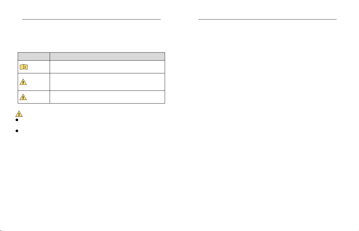
Symbol Conventions
The symbols that may be found in this document are defined as follows.
Symbol Description
NOTE
Provides addional informaon to emphasize or supplement
important points of the main text.
Indicates a potenally hazardous situaon, which if not avoided,
WARNING
DANGER
WARNING
During the installation and utilization of the device, please strictly conform to electrical
safety rules in different nations and regions.
You shall acknowledge that the use of the device with Internet access might be under
network security risks, please strengthen protection for your personal information and data
security. If you find the device might be under network security risks, please contact with us.
could result in equipment damage, data loss, performance
degradaon, or unexpected results.
Indicates a hazard with a high level of risk, which if not avoided, will
result in death or serious injury.
Catalog
Chapter 1 Introducon
1.1 Overview ............................................................................................................................
1.2 Packing List .........................................................................................................................
1.3 Appearance ........................................................................................................................
1.3.1 Front Panel ......................................................................................................................
Chapter 2 Installaon ...............................................................................................................
Chapter 3 Prepare ....................................................................................................................
Chapter 4 Configuraon ..................................................................................................................
1
1
1
1
3
5
7
Page 4

DS-3WF02C-5N/O Quick Start Guide DS-3WF02C-5N/O Quick Start Guide
Indicator
Descripon
Physical Interface
Descripon
Reset
Chapter 1 Introduction
1.1 Overview
DS-3WF02C-5N/O wireless bridge can be applied in industries, such as wireless video
surveillance, railway, transportation, power and other industries, wireless video/data transmission, wireless coverage, carrier wireless backbone network construction, Wi-Fi wireless
coverage, rural information construction, and wireless network coverage. The long-distance
transmission of the device can guarantee multi-channel HD video transmission.
1.2 Packing List
The packing list is shown as below. If any accessories are damaged or lost, keep the package
intact and contact your dealer for replacement.
Name Item Quantity
Device DS-3WF02C-5N/O
PoE Adapter 24 V, 0.5 A 1
Power Cord Power Cord 1
Hoop Hoop for mounng device 1
Quick Start Guide Instrucon manual 1
Table 1-1 Packing List of DS-3WF02C-5N/O
1.3 Appearance
1.3.1 Front Panel
Front panel of DS-3WF02C-5N/O is shown as below.
Front Panel of DS-3WF02C-5N/O
1 2
Figure 1-1 DS-3WF02C-5N/O Front Panel
1
Indicator
Indicators are used to monitor the status of the DS-3WF02C-5N/O. See the following table for
the description of the indicators.
Figure 1-2 Indicators
Power indicator.
If the green light is steady on, it indicates that the power is on.
Network connecon light.
LAN
WLAN
Physical Interface
The hardware interfaces of the DS-3WF02C-5N/O are as follows.
LAN
POE
The light indicates there is one IPC or other network device connects to the LAN port of PoE
adapter.
Blinking means sending data.
Wireless indicator light.
The light indicates that the wireless is enabled.
Blinking means sending data.
Signal strength indicator light.
Red light on, indicang that the signal is weak or no signal.
Yellow and red lights on, indicang signal level is medium.
Green, yellow and red lights on, indicang the wireless signal level is strong
Table 1-2 Indicator Description
Figure 1-3 Physical Interface
The reserved network port can be connected to front-end network devices such as IPC.
Used to restore the default factory sengs.
The network cable is connected to the “POE” on the PoE power module to provide
power and data transmission to the device.
Table 1-3 Physical Interface
Page 5

DS-3WF02C-5N/O Quick Start Guide DS-3WF02C-5N/O Quick Start Guide
Chapter 2 Installation
Step 3 The schematic diagram of the installation of the device is as follows.
Step 1 Select the unobstructed high point around the device to ensure that the devices are
aligned and there is no obstruction in the middle. Fix the device as shown in the figure below.
Attach the back of the device to the pole, use the hoop to pass through the hoop hole on the
back of the device, tighten the hoop, and fix the device on the pole.
PoE
LAN
Figure 2-1 Install host
PoE
LAN
PoE Adapter
Figure 2-3 Finish installation
Step 2 Connect the PoE interface of the device to the PoE interface of the PoE power supply
through the network cable. The LAN interface of the device and the LAN interface of the PoE
power supply can be connected to the front-end network devices such as IPC through the
network cable, as shown in the following figure.
PoE Adapter
LAN
POE
Protective cover
The PoE port of the device is connected to the PoE
port of the PoE adapter through a network cable.
Figure 2-2 Power on the device
3 4
Page 6

DS-3WF02C-5N/O Quick Start Guide DS-3WF02C-5N/O Quick Start Guide
Chapter 3 Prepare
Step 1 Use a network cable to connect the computer to the LAN interface of the device or PoE
power supply to prepare the device. First, you need to configure the computer IP address and
the device's default IP address to be on the same network segment. Take the Windows 7 system
as an example. Click the network logo in the lower right corner of the desktop and click Open
Network & Internet settings-Network and Sharing Center. As shown below.
Network & Internet settings
Change settings,such as makeing a connection metered.
MK-WIFI Airplane mode
Figure 3-1 Network & Internet settings
Step 2 Click “Local Area Connection” on the right and click “Properties”. As shown below.
Mobile
hotspot
ENG
9:43 PM
1/1/2019
Ethernet 2 Properties
Networking
Sharing
Connect using:
ASIX AX88179 USB 3.0 to Gigabit Ethernet Adapter
This connection uses the following items:
Client for Microsoft Networks
File and Printer Sharing for Microsoft Networks
QoS Packet Scheduler
Internet Protocol Version 4(TCP/IPv6)
Microsoft Network Adapter Multiplexor Protocol
Microsoft LLDP Protocol Driver
Internet Protocol Version 6(TCP/IPv6)
Install...
Descripton
Transmission Control Protocol/Internet Protocol. The default
wide area network protocol that provides communication
across diverse interconnected networks.
Configure...
PropertiesUninatall
OK Cancel
Figure 3-3 Internet Protocol Version 4 (TCP/IPv4)
Step 4 Configure the IP address of the computer to be the unused 192.168.1.X address in the
Ethernet 2 Status
General
Connection
IPv4 Connectivity:
IPv6 Connectivity:
Media State:
Duration:
Speed:
Details...
Activity
Sent Received
Bytes:
57,467 117,331
Properties Disable Diagnose
Internet
Internet
Enabled
00:00:35
1.0Gbps
Close
LAN. X is any integer other than 36 in 2 to 253. The subnet mask is 255.255.255.0. Click "OK"
as shown below.
General
You can get IP settings assigned automatically if your network
supports this capablity. Otherwise,you need to ask your network
adminstrator for the appropriate IP settings.
Obtain an IP address automatically
Use the following IP address:
IP address:
Subnet mask:
Default gateway:
Obtian DNS server address automatically
Use the following DNS server addresses:
Preferred DNS server:
Alternate DNS server:
Validate settings upon exit
192 .168 . 1 . 2
255 . 255 . 255 . 0
Advanced...
Figure 3-2 Local Area Connection
Step 3 Double-click Internet Protocol Version 4 (TCP/IPv4). As shown below.
Figure 3-4 Configure the IP
5 6
Page 7

DS-3WF02C-5N/O Quick Start Guide DS-3WF02C-5N/O Quick Start Guide
Chapter 4 Configuration
After the preparation is completed, start the device configuration.
Step 1 Make sure that the IP address of the computer is inconsistent with the default IP address
of the device. On the same network segment, use a browser to log in to the device, open a
browser, and enter the default IP address of the device in the address bar: 192.168.1.36.
NOTE
When you log in to the device for the first time, click Enter, enter the device activate page.
The user name is admin, and the user password is set by the user. You also need to select your
password, country, language and time zone, as shown in Figure 4-1. Check "I agree to these
terms of use" and click "Activate”. Take the AP device as an example.
Username
New Password
Confirm Password
Country/Region
Time Zone
Language
TERMS OF USE
Installer must install this device professionally. It is the installer's responsibility to
follow local country regulations including operation within legal frequency
channels,output power requirements.
I agree to these terms of use
admin
Please set a password
Please confirm the password
Please select country code
Please select time zone
English
This wizard page is only used in bridge mode, helps to set the basic network parameters.
Network
LAN IP:
LAN Netmask:
Gateway IP:
192.168.1.36
255.255.255.0
192.168.1.100
Figure 4-2 Wizard – Network
Step 3 Go to the “Wireless” page. The device can modify the wireless parameters such as
network name, frequency, and key through this page. The default wireless mode of the device is
the WDS Station. The default network name of the device is Wireless_R. When pairing with the
WDS Access Point device, please note that the key and the SSID on the WDS Station side must
be the same as the WDS Access Point. Other configurations are recommended to keep the
default values. Click "Next".
This wizard page helps to set the basic wireless and wireless security,Please click the top”Wireless”menu for
detail setting.
Wireless
Wireless Mode:
IEEE802.11 Mode:
Channel Width:
Wireless Security[?]:
WPA2-PSK Key:
WDS Station
Wireless_R
SSID:
Output Power:
Caution:It is installer`s responsibility to follow local regulations while
adjusting the transmission power
A/N mixed
20 MHz
WPA
Allowing adjusting transmission power
Figure 4-1 login
Step 2 Go to the device page and click the “Wizard” bar at the top of the page to enter the
“Network” page to set the IP address of the device. In the address field of the LAN IP, fill in
Step 4 Go to the Setup “Wizard – Finish” page and click “Change” to save the configuration.
Figure 4-3 Wizard – Wireless
192.168.1.X, X is any integer from 2 to 253, and the address is not used. The subnet mask can be
used by default. Click “Next” when finished.
7 8
Page 8

DS-3WF02C-5N/O Quick Start Guide
Wizard-Finish
You have finished the wizard.
please click ’Change’to save all your settings,and click’Apply’to reboot and make your settings work.
Figure 4-4 Wizard – Finish
Users can also click the “Wireless” bar at the top of the page to enter the “Wireless” page
and modify the network name, frequency, key and other parameters.
WDS Station
Wireless_R
SSID:
Antenna Gain:
Output Power:
Caution:It is installer`s responsibility to follow local regulations while
adjusting the transmission power
A/N mixed
Argentina
Country Code:
20 MHz
MCS 15-130(144)
Lock AP Mac:
Security:
WPA
Mode:
WPA2
Cypher:
CCMP
WPA Key:
Allowing adjusting transmission power
Show
Basic Wireless Settings
Wireless Security Settings
Wireless Mode[?]:
IEEE 802.11 Mode:
Channel Width[?]:
Max TX Rate,Mbps[?]:
Figure 4-5 Wireless
For the WDS Access Point device configuration, please refer to the WDS Station device
configuration.
9
 Loading...