

Page 1

Network PTZ Camera·Quick Start Guide
i
Network PTZ Camera
Quick Start Guide
Page 2

Network PTZ Camera·Quick Start Guide
i
Quick Start Guide
COPYRIGHT ©2018 Hangzhou Hikvision Digital Technology Co., Ltd.
ALL RIGHTS RESERVED.
Any and all information, including, among others, wordings, pictures,
graphs are the prop erties of Hangzhou Hikvision Digital Technology
Co., Ltd. or its sub sidiaries (hereinafter r eferr ed to be “Hikvision”).
This user manual (hereinafter ref erred to be “the Manual”) cannot
be reproduced, cha nged, translated, or distributed, partially or
wholly, by any mean s, without the prior written permission of
Hikvision. Unles s otherwise stipulated, Hikvision does not make any
warranties, guarantees or representations, express or implied,
regarding to the Manual.
About this Manual
This Manual is applicable to Network PTZ Camera.
The Manual includ es instructions for using and managing the
product. Pictures, charts, images and all other information
hereinafter are for description and explanation only. The
information co ntained in the Manual is subject to change, without
notice, d ue to firmware updates or other rea sons. Please find the
latest version in the company website
(http://oversea s.hikvision.com/en/
Please use this user manual under the guidance of prof essionals.
Trademarks Acknowledgement
and other Hikvision’s trademarks and logos are the
properties of Hikvision in various jurisdictions. Othe r trademarks and
logos mentioned below are the propert ies of their respecti ve
owners.
).
Page 3

Network PTZ Camera·Quick Start Guide
ii
Legal Disclaimer
TO THE MAXIMUM EXTENT PERMITTED BY APPLICABLE LAW, THE
PRODUCT DESCRIBED, WITH ITS HAR DWARE, SOFTWARE AND
FIRMWARE, IS PROVIDED “AS IS”, WITH ALL FAULTS AND ERRORS,
AND HIKVISION MAKES NO WARRANTIES, EXPRESS OR IMPLIED,
INCLUDING WITHOUT LIMITATION, MERCHANTABILITY,
SATISFACTORY QUALITY, FITNESS FOR A PARTICULAR PURPOSE, AND
NON-INFRINGEMENT OF THIRD PARTY. IN NO EVENT WILL HIKVIS ION,
ITS DIRECTORS, OF FICERS, EMPLOYEES, OR AGENTS BE LIABLE TO
YOU FOR ANY SPECIAL, CON SEQUENTIAL, INCIDENTAL, OR INDIRECT
DAMAGES, INCLUDING, AMONG OTHERS, DAMAGES FOR LOSS OF
BUSINESS PROFITS, BUSINESS INTERRUPTION, OR LOSS OF D ATA OR
DOCUMENTATION, IN CONNECTION WITH THE USE OF THI S
PR O D UCT, EVEN IF HIKVIS ION HAS BEEN ADVISED OF THE
POSSIBILITY O F SUCH DAMAGES.
REGARDING TO THE PRODUCT WITH INTERNET ACCES S, THE USE OF
PRODUCT SHALL BE WHOLLY AT YOUR OWN RISKS. HIKVISION SHALL
NOT TAKE ANY RESPONSIBILITES FOR ABNORMAL OPERATION,
PRIVACY LEAKAGE OR OTHER DAMAGES RESULTING FROM CYBER
ATTACK, HACKER ATTACK, VIRUS IN SPECTION , OR OTHER INTERNET
SECURITY RISK S; HOWEVER, HIKVISION WILL PROVIDE TIMELY
TECHNICAL SUPPORT IF REQUIRED.
SURVEILLANCE LAWS VARY BY JURISDICTION . PLEASE CHECK ALL
RELEVANT LAWS IN YOUR JURISDICT ION BEFORE USING THIS
PRODUCT IN ORDER TO ENSURE THAT YOUR USE CONFORMS THE
APPLICABL E LAW. HIKVISION SHALL NOT BE LIABLE IN THE EVENT
THAT THIS PRODUCT IS USED WITH ILLEGITIMATE PURPOSES.
Page 4

Network PTZ Camera·Quick Start Guide
iii
IN THE EVENT OF ANY CONFLICTS BETWEEN THIS MANUAL AND THE
APPLICABLE LAW, THE LATER PREVAILS.
0505171080913
Page 5

Network PTZ Camera·Quick Start Guide
Regulatory Information
FCC Information
Please take attention that changes or modification not expressly
approved by the party responsi ble for compliance could void the
user’s authority to operate the equipment.
FCC compliance: This equipment has been tested and found to
comply with the limits for a Class B digital device, pursuant to part 15
of the FCC Rul es. Thes e limits are designed to provide reasonable
protection against harmful interference whe n the equipment is
operated in a commercial environment. This equip ment generates,
uses, and can radiate radio frequency energy and, if not installed and
used in accordance with the instruction manual, may cause harmful
interference to radio communications. Operation of this equipment
in a residential area is likely to cause harmful interference in which
case the user will be required to correct t he interfere nce at his own
expense.
FCC Conditions
This device complies with part 15 of the FCC Rules. Operation is
subject to the following two conditions:
1. This device may not caus e harmful interference.
2. This device must accept any interference received, inclu ding
interference that may cause undesired operation.
This equipment complies with FCC/IC RSS-102 radiation exposure
limits set forth for an uncontrolled environment. This equipment
should be installed and operated with minimum distance 20cm
between the radiator & your body.
iv
Page 6
Network PTZ Camera·Quick Start Guide
v
EU Conformity Statement
This product and - if applicable - the supplied
accessories too are marked with "CE" and comply
therefore with the applicable harmoni zed European
standards listed under the Low Voltage Directive
2015/35/EU, the EMC Directive 2014/30/EU, the RoHS Directive
2011/65/EU.
2012/19/EU (WEEE directive): Products marked
with this symbol cannot be disposed of as unso rted
municipal waste in the European Union. For proper
recycling, return this product to your local supplier
upon the purchase of equivalent new equipment,
or dispose of it at designated collection points. For more information,
please see: www.recyclethis.info.
2006/66/EC (battery directive): This product
contains a battery that cannot be disposed of as
unsorted municipal waste in the European Union.
See the product docu mentat ion for specific battery
information. The battery is marked with this symbol,
which may include lettering to indicate cadmium (Cd), lead (Pb), or
mercury (Hg). For proper recycling, return the battery to your
supplier or to a designated collection point. For more information,
please see: www.recyclethis.info
Industry Canada ICES-003 Compliance
This devic e meets the CAN ICES-3 (A)/NMB-3(A) standards
requirements.
.
Page 7
Network PTZ Camera·Quick Start Guide
vi
Safety Instruction
These instructions are intended to ensure that user can use the
product correctly to avoid danger or property loss.
The precaution measur e is divided into “Warnings” and “Cautions”
Warnings: Serious injury or death may occur if any of the warnings
are neglected.
Cautions: Injury or equip ment damage may occur if any of the
cautions are neglected.
Warnings Fol low these
safeguards to prevent
serious injury or death.
Cautions Follow these
precautions to prevent
potential injury or material
damage.
Warnings
In the use of the product , you must be in strict compliance with
the electrical safety regulations of the nation and region.
Refer to technical specifications for detailed information.
Input voltage should meet both the SELV (Safety Extra Low Voltage)
and the Limited Power Source with 24 VAC or 12 VDC according to
the IEC60950-1 standard. Refer to technical specifications for
detailed information.
Page 8

Network PTZ Camera·Quick Start Guide
vii
Do not connect several devices to one power adapter as adapter
overload may cause over-heating or a fire hazard.
Make sure that the plug is firmly connected to the power socket.
Make sure that the power has been disconnected before you wire,
install or dismantle the PTZ c amera.
When the product is mounted on wall or ceiling, the device shall
be firmly fixed.
If smoke, odor or noise rise from the d evice, turn off the power at
once and unplug the pow er cable, and th en contact the service
center.
If the product does not work properly, contact your dealer or th e
nearest servi ce cente r. Never attempt to disassemble the camera
yourself. (We shall not assume any responsibility for probl ems
caused by unauthori zed repair or maintenance.)
Cautions
If the camera fails to synchroni ze local time with that of the
network, you need to set up camera time manually. Visit the
camera (via web browser or client software) and enter system
settings interface for time settings.
Make sure the power supply voltage is correct before u sing the
camera.
Do not drop the camera or subject it to physical shock, and do not
expose it to high electromagnetism radiation. Avoid installation on
vibrations surface or places subject to shock (ignorance can cause
device da mage).
Page 9

Network PTZ Camera·Quick Start Guide
viii
Do not touch sen or modules with fingers. If cleaning is necessary,
use clean cloth with a bit of ethanol and wipe it gently. If the
camera will not be used for an extended period, replace the lens
cap to protect the sensor from dirt.
Do not aim the camera at the sun or extra bright places. Blooming
or smearing may occur otherwise (which is not a malfunction),
and affect the endurance of sensor at the same time.
The sensor may be burned out by a laser beam, so when a ny laser
equipment is in using, make sure that the surface of sensor will
not be exposed to the laser beam.
Do not place the camera in extremely hot, cold, dusty or damp
locations, and do not expose it to high electromagnetic radiation.
To avoid heat accumulation, good ventilation is required for
operating environment.
Keep the camera away from liquid while in use.
While in delivery, the camera shall be packed in its original packing,
or packing of the same texture.
Improper use or replacement of the battery may result in hazard
of explosion. Replace with the same or equivalent type only.
Dispose of used batteries according to the instructions provided
by the battery manufactur er.
Page 10

Network PTZ Camera·Quick Start Guide
ix
Table of Contents
1 Overview ....................................................................................1
1.1 Introduction ................................................................................... 1
1.2 Cable Descriptions ......................................................................... 1
1.3 Alarm Output ................................................................................. 2
2 Installation .................................................................................4
2.1 Installing the Memory Card .......................................................... 4
2.1.1 DE1Axxx(I) Series PTZ Camera ............................................... 4
2.1.2 DE2Axxx(I) Series PTZ Camera ............................................... 8
2.1.3 DE2xxx(I) Series PTZ Camera ................................................. 8
2.1.4 DE3xxx Series PTZ Camera..................................................... 9
2.1.5 DY3xxx Series PTZ Bullet Camera ........................................ 10
2.1.6 DE4AxxxI Series PTZ Camera ............................................... 10
2.2 Installing DE1Axxx(I) Series PTZ Camera .................................... 12
2.2.1 Ceiling Mounting .................................................................. 14
2.2.2 Wall Mounting...................................................................... 16
2.3 Installing DE2Axxx(I) Series PTZ Camera .................................... 18
2.4 Installing DE2xxx(I) Series PTZ Camera....................................... 18
2.4.1 Wall Mounting...................................................................... 19
2.4.2 Ceiling Mounting .................................................................. 23
2.4.3 Installing with Junction Box ................................................. 28
2.5 Installing DE3xxx Series PTZ Camera .......................................... 31
2.5.1 Ceiling Mounting .................................................................. 31
2.5.2 In-ceiling Mounting .............................................................. 33
2.6 Installing DY3xxx Series PTZ Bullet Camera ............................... 36
2.6.1 Dimension s of DY3xxx Series PTZ Bullet Camera ............... 36
2.6.2 Wall Mounting...................................................................... 38
2.6.3 Base Mounting ..................................................................... 39
Page 11

Network PTZ Camera·Quick Start Guide
x
2.7 Installing DE4AxxxI Series PTZ Camera ....................................... 40
2.7.1 Ceiling Mounting .................................................................. 41
2.7.2 In-ceiling Mounting .............................................................. 41
3 Setting the PTZ Camera over the LAN ........................................ 44
3.1 Wiring ........................................................................................... 54
3.2 Activating the Camera ................................................................. 55
3.2.1 Activation via Web Browser ................................................ 55
3.2.2 Activation via SADP Software .............................................. 57
3.3 Modifying the IP Address ............................................................ 58
4 Accessing via Web Browser ....................................................... 61
5 Operating v ia Hik-Connect App.................................................. 64
5.1 Enable Hik-Connect Se rvice on Camera ..................................... 64
5.1.1 Enable Hik-Connect S ervice via SADP Software ................. 64
5.1.2 Enable Hik-Connect Service via Web Browser ................... 65
5.2 Hik-Connect Setup ....................................................................... 67
5.3 Adding Camera to Hik-Connect .................................................. 67
5.4 Initializing the Memory Card ...................................................... 69
Page 12

Network PTZ Camera·Quick Start Guide
1
1 Overview
1.1 Introduction
The network PTZ camera has the following series:
DE1Axxx(I) Series PTZ Ca mera
DE2Axxx(I) Series PTZ Ca mera
DE2xxx(I) Series PTZ Came ra
DE3xx x Series PTZ Came ra
DY3xxx Series PTZ Bullet Camera
DE4AxxxI Series PTZ Camera
Integra ted with an optical zoom lens, this series of cam eras feature
in the PTZ limits, 3D positioning, Day/Night auto switch, 3D DNR, etc.,
and are widely applied in various kinds of environments.
1.2 Cable Descriptions
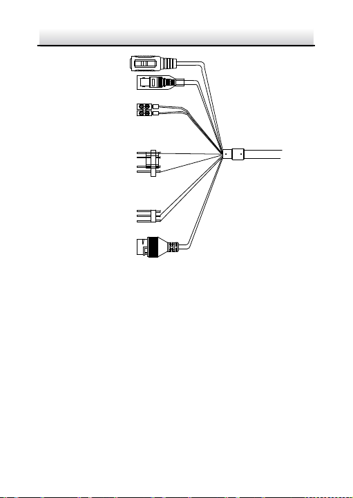
The cable interfaces of network PTZ camera are shown in Figure 1-1.
The cables are distinguished by different colors. Refer t o the labels
attached on the cables for identification.
Notes:
The cables vary depending on different camera models.
Make sure th e camera is power-off before you connect the
cables.
Page 13
Network PTZ Camera·Quick Start Guide
2
Network Cable
Video Cable
Power Cord
.
.
.
DC12
V IN
RS-485
Alarm Cable
Audio Cable
Figure 1-1 Cables of PTZ Camera
Power Cord: Supports 12 VDC power supply.
Video Cable: Connect BNC Cable to test the video output.
Alarm Cable: Connect terminal ALARM-IN with GND interface,
Audio Cable: Connect terminal AUDIO-IN with GND interface.
and connect terminal ALARM-OUT with ALARM-COM i nte rfa ce .
Network Cable: Connect the network interface with network
cable.
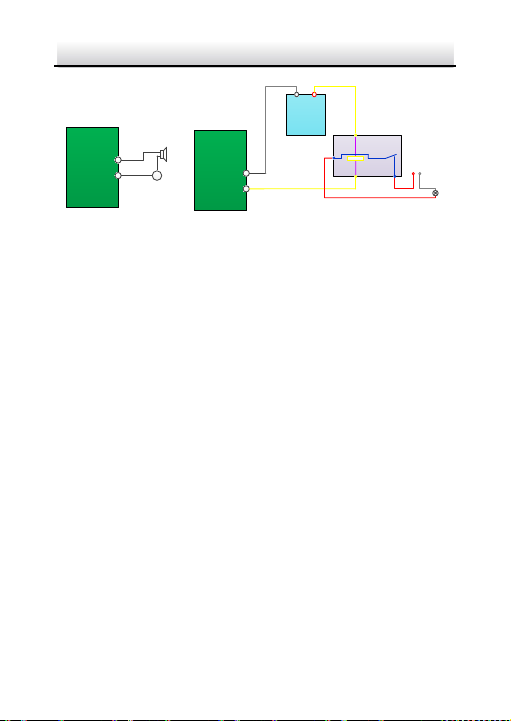
1.3 Alarm Output
Alarm output is shown in Figure 1-2.
Page 14
3
Relay Output
OUT (n)
DC
OUT (n)
Direct load
+
-
Relay Output
OUT (n)
OUT (n)
DC 30V
1A
Power Supply
GND Output
~
220V AC
FireWire
Zero
Line
JQC-3FG
Relay
(10A 250VAC)
Network PTZ Camera·Quick Start Guide
Figure 1-2 Alarm Output
Page 15

Network PTZ Camera·Quick Start Guide
4
2 Installation
Before you start:
Check the package contents and make sure that the device in the
package is in good condition and all the assembly parts are included.
Notes:
Do not drag the PTZ ca mera with its waterproof cables;
otherwise the waterproof performanc e is affected.
Do not touch the bubble directly by hand. The image blurs
otherwise.
Do not power up the camera until the installation is finished. To
ensure the safety of personnel and equipment , all the
installation steps should be done with power supply off.
2.1 Installing the Memory Card
You can install the memory card for local storage.
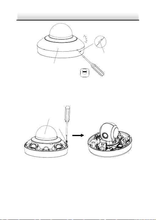
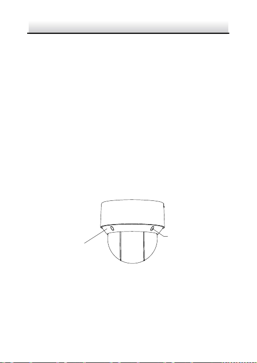
2.1.1 DE1Axxx(I) Series PTZ Camera
Steps:
1. Open the cover with the straight screwdriver from a crack on the
cover, as shown in Figure 2-1.
Page 16
Network PTZ Camera·Quick Start Guide
5
2.0
Cover
Crack
Bubble
Screw
Figure 2-1 Open the Cover
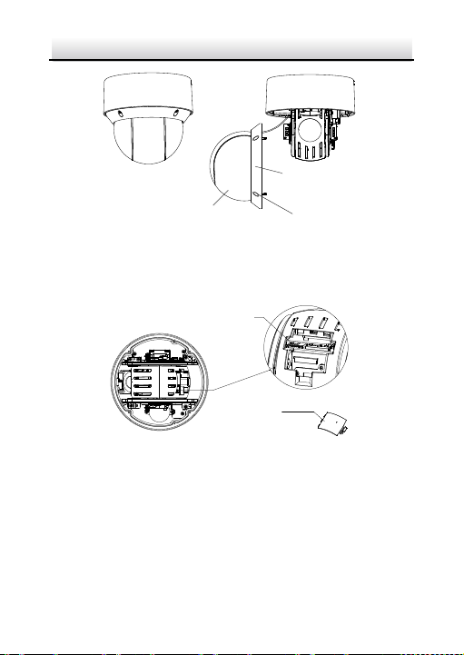
2. Unscrew the screws o n the cam era base with the cross screwdri ver,
and remove the bubble, as shown in Figure 2-2.
Figure 2-2 Remove the Bubble
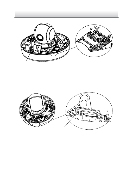
3. The position of memory card are various according to different
camera model .
Type I : open the memory card slot in the camera, and insert the
memory card.
Page 17
Network PTZ Camera·Quick Start Guide
6
Reset
Memory Card Slot
Memo ry Card Slot
Reset
Figure 2-3 Insert the Memory Card
Type II: align the memory card with the memory card slot and
insert it.
Figure 2-4 Insert the Memory Card
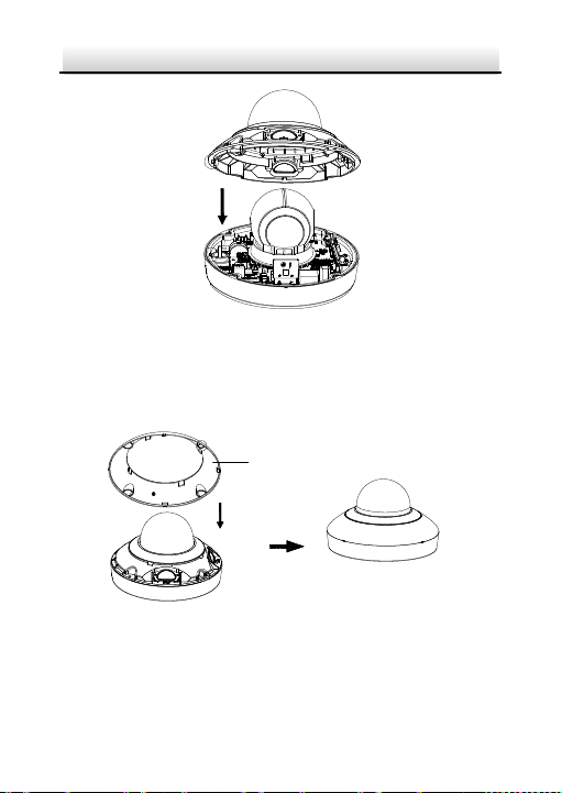
4. Align the bubble with the came ra base, and install the bubble back.
Fix the bubble with four screws, as shown in Figure 2-5.
Page 18
Network PTZ Camera·Quick Start Guide
7
Cover
Figure 2-5 Install the Bubble
5. Align the cover with the camera, and install the cover back, as
shown in Figure 2-6.
Figure 2-6 Install the Cover
Page 19
Network PTZ Camera·Quick Start Guide
8
Memory Card Cover
Memory Card Cover
2.1.2 DE2Axxx(I) Series PTZ Camera
Note:
The installation steps are similar to the installation steps of
DE1Axxx(I) series camera. Refer to section 2.1.1 DE1Axxx(I) Series
PTZ Camera.
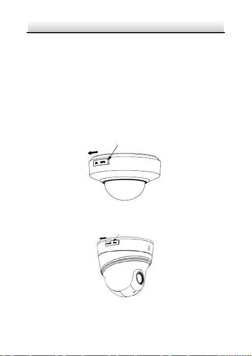
2.1.3 DE2xxx(I) Series PTZ Camera
Steps:
1. Open the memory card cover.
Figure 2-7 DE2xxx Series PTZ Cam era
Figure 2-8 DE2xxxI Series (IR) PTZ Ca mera
Page 20

Network PTZ Camera·Quick Start Guide
9
Reset
Debug Memory Card
2. Rotate the cover to a proper position, align the memory card with
the memory card slot and insert it.
Figure 2-9 Insert the Memory Card
3. Rotate the cover and push it back.
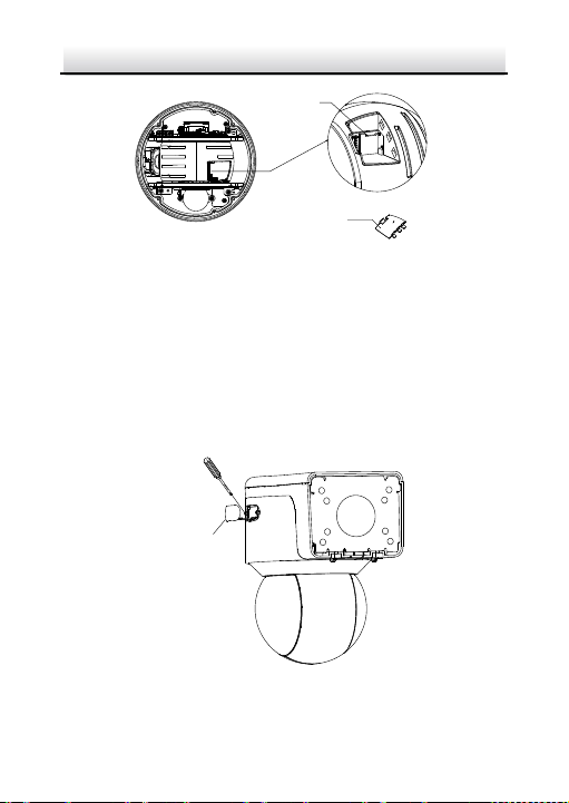
2.1.4 DE3xxx Series PTZ Camera
Steps:
1. Loosen three screws on the bottom of camera to reveal the
memory card slot, as shown in Figure 2-10.
Figure 2-10 DE3xxx Series PTZ Camera
Page 21
Network PTZ Camera·Quick Start Guide
10
Silicone Plug
Decorative Rim
2. Align the memory card with the memory card slot and insert it.
3. Fix the screws and assemble the PTZ camera.
2.1.5 DY3xxx Series PTZ Bullet Camera
For DY3xxx series PTZ bullet camera, the memory card slot is in the
camera module and if you need, the memory card can be installed
before the ca me ra leaves the fa ctor y. In order to prevent damage ,
we highly recommend that you do not disassemble the PTZ bullet
camera by yourself.
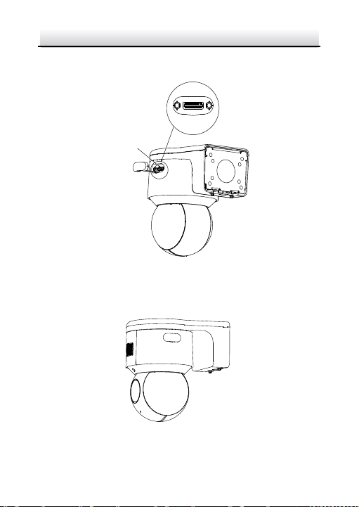
2.1.6 DE4AxxxI Series PTZ Camera
Steps:
1. Remove the four silicone plugs on the decorative rim as shown in
Figure 2-11, and you can see four flange screw s in the deco rative
rim.
Figure 2-11 Remove the Silicone Plugs
2. Loosen four flange screws with a screwdriver. Remove the bubble
and the decorati ve rim as shown in Figure 2-12.
Page 22
Network PTZ Camera·Quick Start Guide
11
Bubble
Flange Srews
Decorative Rim
Memory Card Slot
Memory Card Cover
Figure 2-12 Remove the Bubble and the Deco rative Rim
3. Open the memory card cover and insert the memory card into the
card slot as shown in Figure 2-13 and Figure 2-14.
Figure 2-13 For 20× Camera Module
Page 23
Network PTZ Camera·Quick Start Guide
12
Memory Card Slot
Memory Card Cover
Memory card cover
Figure 2-14 For 4× Camera Module
4. Close the mem ory card cover. Fix the four flange screws and push
four silicone plugs back to assembl e the PTZ camera.
2.1.7 DE3AxxxI Series PTZ Camera
Steps:
1. Pull the decorative cover out and loos en 2 screws on memory card
cover with screwdri ver as shown in Figure 2-15.
Figure 2-15 Open the m emory card cover
Page 24
Network PTZ Camera·Quick Start Guide
13
Memory card
2. Remove the memory card cover, including sealing ring, and insert
the memory card as printed mark.
Figure 2-16 Insert the memory card
3. Screw the memory cover back, making sure the sealing ring is flat,
and then close the d ecorative cover.
Figure 2-17 Complete the memory card installation
Page 25
Network PTZ Camera·Quick Start Guide
14
Installation Plate
OPEN
2.2 Installing DE1Axxx(I) Series PTZ Camera
2.2.1 Ceiling Mounting
Notes:
The thickness of the ceiling shall range from 5 mm to 40 mm.
Make sure the ceiling is strong enough to withstand more than
four times the weight of the PTZ camera and its accessories.
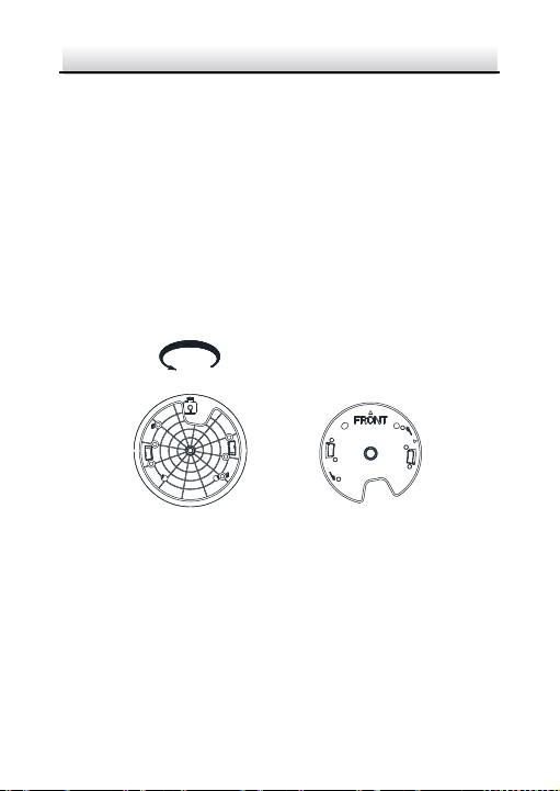
Steps:
1. Rotate the installation plate anticlockwise, and remove the
installation plate, as shown in Figure 2-15.
Figure 2-18 Remove the Installation Plate
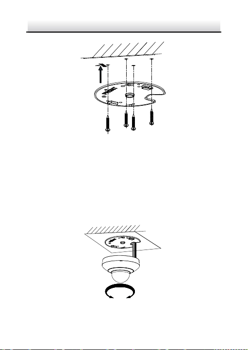
2. Drill four screw holes in the ceiling according to the installation
plate.
3. Align the installation plate with the screw holes, and fix the
installation plate on the ceiling.
Page 26
Network PTZ Camera·Quick Start Guide
15
OPEN
LOCK
Figure 2-19 Fix the Installation Plate
4. Route the cables from the cabl e hole in the installation plate.
Note:
Water-proof treatment is required for cable connectors. Refer to
section 2.9 and 2.10 for details.
5. Align the camera with the installation plate, and rotate the camera
clockwise to fix it, as shown in Figure 2-17.
Figure 2-20 Fix t he Came ra
Page 27

Network PTZ Camera·Quick Start Guide
16
2.2.2 Wall Mounting
Notes:
For cement wall, you need to use the expansion screw to fix the
brac ket. The mounting hole of the expansion pipe on the wall
should align with the mounting hole on the bra cket.
For wooden wall, you can just use the self-tapping screw to fix
the bra cke t.
Make sure that the wall is strong enough to withstand more
than eight times the weight of the PTZ camera and its
accessori es.
Steps:
1. Remove the installation plate, and install it on the wall mounting
bracket (not supplied) with two screws.
Note:
Refer to step 1 in section 2.2.1 Ceiling Mounti ng to remove t he
installation plate.
Figure 2-21 Install the Installation Plate
2. Loosen the fi xing screw on the bracket and rem ove the b racket
base.
Page 28

Network PTZ Camera·Quick Start Guide
17
Fixing Screw
Bracket Base
OPEN
LOCK
Figure 2-22 Remove the Bracket Base
3. Install the bracket base on the wall with four screws.
Figure 2-23 Install the Bracket Base
4. Route the cables. Align the camera with the installation plate on
the wall mounting bracket, and rotate the camera clockwise to fix
it on the bracket.
Figure 2-24 Install the Camera
Page 29

Network PTZ Camera·Quick Start Guide
18
5. Connect the cables. Install the wall mounting bracket to the
bracket base on the wall, and fix it with the supplied sc re w.
Note:
Water-proof treatment is required for cable connectors. Refer to
section 2.9 and 2.10 for details.
Figure 2-25 Fix the Bracket
6. Remove the protective film after installation.
2.3 Installing DE2Axxx(I) Series PTZ Camera
Note:
The installation steps are similar to the installation steps of
DE1Axxx(I) series camera. Refer to section 2.2 Installing DE1Axxx(I)
Series PTZ Camera.
2.4 Installing DE2xxx(I) Series PTZ Camera
DE2xxx series PTZ cam era supports wall mounting, ceiling mounting,
and installing with junction box . DE2xxxI Series (IR) PTZ camera
supports wall mounting and ceiling mounting.
Page 30

Network PTZ Camera·Quick Start Guide
19
Front View of Base Plate
OPEN
Base Plate on the Bottom of the Dome
2.4.1 Wall Mounting
Notes:
For cement wall, you need to use the expansion screw to fix the
brac ket. The mounting hole of the expansion pipe on the wall
should align with the mounting hole on the bra cket.
For wooden wall, you can just use the self-tapping screw to fix
the bra cke t.
Make sure that the wall is strong enough to withstand more
than eight times the weight of the PTZ camera and its
accessori es.
Steps:
1. Rotate the base plate counterclockwise to separate it from the PTZ
camera.
Figure 2-26 Base Plate for DE2xxx Series PTZ Camera
Page 31

Network PTZ Camera·Quick Start Guide
20
Front View of Base PlateBase Plate on the Bottom of the Dome
OPEN
Figure 2-27 Base Plate for DE2xxxI Series (IR) PTZ Camera
2. Align the cable hole on the base plate with the hole on the b racket
for wiring. And install the base plate to the bra cket by fixing three
PM4
×10 screws (supplied) to the holes marked with digit “2” on
the bra cke t.
Figure 2-28 For DE2xxx Series PTZ Camera
Page 32

Network PTZ Camera·Quick Start Guide
21
LOCKOPEN
Figure 2-29 For DE2xxxI Series (IR) PTZ Camera
3. Route the cables through the cabl e hole.
4. Align the PT Z camera with the base plate. Rotate the PTZ c ame ra
clockwise to the bas e plate, and the PTZ camera is secured with
the base plate by three locks on the plate.
Figure 2-30 Secure DE2xxx Series PTZ Camera
Page 33

Network PTZ Camera·Quick Start Guide
22
LOCK
OPEN
Figure 2-31 Secure DE2xxxI Series (IR) PTZ Camera
5. Secure the mounting base to the wall with four PA 4×25 screws
(supplied).
Figure 2-32 Install the Mounting Base
6. Install the PTZ camera to the bracket.
1). Route the cables of the P TZ camera through the wall bra cket .
2). Connect the corresponding cables.
3). Hang the bracket together with the PTZ camera on the
mounting base.
4). Fix the mounting base with a PM4
×10 screw.
Page 34

Network PTZ Camera·Quick Start Guide
23
Figure 2-33 Secure the Mounting Base
Note:
Water-proof treatment is required for cable connectors. Refer to
section 2.9 and 2.10 for details.
2.4.2 Ceiling Mounting
Purpose:
There are t wo ceiling mounting types pr ovided for the cam era, and
we take the mounting without the junction box as the example.
Notes:
The ceiling mounting is applicable to the indoor/outdoor solid
ceiling construction. The followings are the mandatory
precondition for ceiling mounting:
The thickness of the ceiling shall range from 5 mm to 40 mm.
Make sure the ceiling is strong enough to withstand more than
four times the weight of the PTZ camera and its accessories.
Wiring
The cables of PTZ camera can be routed either from the top or the
side of the back box, as shown in Figure 2-31 and Figure 2-32.
Page 35

Network PTZ Camera·Quick Start Guide
24
For the cables routed from the top of the back box, it is required to
drill a cable hole in the ceiling.
Figure 2-34 Cabling for DE2xxx Series PTZ Camera
Figure 2-35 Cabling for DE2xxxI Series (IR) PTZ Camera
Note:
Water-proof treatment is required for cable connectors. Refer to
section 2.9 and 2.10 for details.
Ceiling Mounting without Junction Box
Steps:
1. Rotate the base plate counterclockwise to sepa rate it from the PTZ
camera, as shown in Figure 2-23 and Figure 2-24.
2. Attach the drill template (supplied) to the place where you want
to fix the PTZ camera, and make sure the front arrow appoints to
the monitoring area.
Page 36

Network PTZ Camera·Quick Start Guide
25
Cable Slot Cover
Figure 2-36 Attach the Drill Template
3. Drill a cable hole in the ceiling according to the circle A on the
template if you want to route the cables through the ceiling. Pull
out the cable slot cover if you want to route the cables on the
surface of t he ceiling, as shown in Figure 2-34.
Figure 2-37 For DE2xxx Series PTZ Ca mera
Page 37

Network PTZ Camera·Quick Start Guide
26
Cable Slot C over
Figure 2-38 For DE2xxxI Series (IR) PT Z Ca mera
4. Attach the base plate to the ceiling and secure it with the supplied
three self-tapping screws by aligning with three screw holes in the
ceiling, and the front arrows on the drill template and base plate
should be aligned together as well, as shown in Figure 2-36 and
Figure 2-37.
Figure 2-39 For DE2xxx Series PTZ Ca mera
Page 38

Network PTZ Camera·Quick Start Guide
27
OPEN LOCK
LOCK
OPEN
Figure 2-40 For DE2xxxI Series (IR) PT Z Ca mera
5. Route the cables through the cabl e hole.
6. Align the PT Z camera with the base plate. Rotate the PTZ camera
clockwise into the base plate, and the PTZ came ra is secured with
the base plate by three locks on the plate.
Figure 2-41 Secure the PTZ Camera
Page 39

Network PTZ Camera·Quick Start Guide
28
Front View of Base Plate
OPEN
Base Plate on the Bottom of the Dome
2.4.3 Installing with Junction Box
Notes:
The thickness of the ceiling shall range from 5 mm to 40 mm.
Make sure the ceiling is strong enough to withstand more than
four times the weight of the P TZ camera and its accessories.
Steps:
1. Rotate the base plate counterclockw ise to sepa rate it from the PTZ
camera.
Notes:
The base plate is not required when you install the PTZ
camera with junction box . Keep it properly.
The junction box is the optional accessory. Get it prepared
before installation.
Figure 2-42 For DE2xxx Series PTZ Ca mera
Page 40

Network PTZ Camera·Quick Start Guide
29
Front View of Base PlateBase Plate on the Bottom of the Dome
OPEN
Figure 2-43 For DE2xxxI Series (IR) PT Z Ca mera
2. Attach the drill template (supplied) to the place where you want
to fix the PTZ camera, and make sure the front arrow appoints to
the monitoring area.
3. Insert two PM4
2-41.
4. Attach the junction box to the ceiling and secure it by aligning the
holes with two screws and rotating the junction box according to
the direction as shown in Figure 2-42. Ma ke su re the front arrows
×10 screws into the ceiling, as shown in Figure
Figure 2-44 Attach the Drill Template
Page 41

Network PTZ Camera·Quick Start Guide
30
Cable Outlet
OPEN LOCK
on the drill template and junction box should be aligned together
as well.
Figure 2-45 Fix the Junction Box
5. Connect the cables and route the cables clockwise through the
hooks and fix the camera and the junction box w it h three hooks.
Tighten it clockwise and loosen it anticlockwise.
Figure 2-46 Fi x t he Came ra
Page 42

Network PTZ Camera·Quick Start Guide
31
6. Secure the PTZ camera an d remove th e protective fil m.
2.5 Installing DE3xxx Series PTZ Camera
DE3xxx series PTZ cam era supports ceiling mounting and in-ceiling
mounting.
Note:
Wall mounting, installation with junction box, and installation with
tripod are supported for DE3xxx series PTZ camera. The
corresponding accessories shall be purchased separately.
2.5.1 Ceiling Mounting
Notes:
The thickness of the ceiling shall range from 5 mm to 40 mm.
Make sure the ceiling is strong enough to withstand more than
four times the weight of the PTZ camera and its accessories.
Steps:
1. Attach the drill template (supplied) to the place where you want
to fix the PTZ camera, and make sure the front arrow appoints to
the monitoring area.
2. Drill a cable hole in the ceiling according to the circle A on the
template if you want to route the cables through the ceiling, as
shown in Figure 2-44.
Page 43

Network PTZ Camera·Quick Start Guide
32
Figure 2-47 Attach the Drill Template
3. Insert the expansion screws into the ceiling. (Optional)
4. Insert four PM4
as shown in Figure 2-45. Make sure the FRONT arrow of the base
plate is of the same direction as the arrow of the drill template.
5. Connect the cables and route the cable through the cabl e outlet.
Align the PTZ cam era with the base plate. Rotate the PTZ camera
×10 screws into the ceiling and fix the base plate,
Figure 2-48 Fix the Base Plate
Page 44

Network PTZ Camera·Quick Start Guide
33
①
OPEN LOCK
②
③
clockwise into the base plate, and the PTZ cam era is secured with
the base plate by three locks on the plate.
Note:
Water-proof treatment is required for cable connectors. Refer to
section 2.9 and 2.10 for details.
6. Fix the screws on the side with a screwdriver, as shown in Figure
2-46.
Figure 2-49 Fix the Camera
7. Secure the PTZ camera an d remove th e protective fil m.
2.5.2 In-ceiling Mounting
Notes:
Reserve at l east 250 mm of height for in-ceiling mounting.
The thickness of the ceiling shall range from 5 mm to 40 mm.
Make sure the ceiling is strong enough to withstand more than
four times the weight of the PTZ camera and its accessories.
Steps:
Page 45

Network PTZ Camera·Quick Start Guide
34
1. Attach the drill template (supplied) to the place where you want
to fix the PTZ camera, and drill a hole in the ceiling according to
the template.
Figure 2-50 Drill Template
2. Fix the base plate onto the in-ceiling bracket with the four screws
in the package (supplied). Make sure that the cable holes of the
base plate are aligned to the cable holes of the bracket, as shown
in Figure 2-48.
Figure 2-51 Fix the Base Plate to In-ceiling Bracket
Page 46

Network PTZ Camera·Quick Start Guide
35
①
OPEN LOCK
②
③
3. Connect the cables and route the cable through the cable hole.
Note:
Water-proof treatment is required for cabl e connectors. Refer to
section 2.9 and 2.10 for details.
4. Align the PT Z camera with the base plate. Rotate the PTZ c ame ra
clockwise into the base plate, and the PTZ came ra is secured with
the base plate by three locks on the plate.
5. Fix the screws on the side with a screwdriver, as shown in Figure
2-49.
Figure 2-52 Fi x t he Came ra
6. Fix the decorati ve rim with the bubble and the dec orative rim will
be attached to the in-ceiling bracket automatically, as shown in
Figure 2-50.
Page 47

Network PTZ Camera·Quick Start Guide
36
Figure 2-53 Assemble the Decorative Rim
7. Secure the camera and rem ove the prot ective film.
2.6 Installing DY3xxx Series PTZ Bullet Camera
2.6.1 Dimensions of DY3xxx Series PTZ Bullet Camera
Two structures of DY3xxx Series PTZ bullet cameras are available:
wall-mounted PTZ bullet camera and base-mounted PTZ bullet
camera.
Select the proper PTZ bullet camera and the installation method
according to its working environment.
Dimensions of wall-mounted PTZ bullet camera is shown in
Figure 2-51.
Page 48

Network PTZ Camera·Quick Start Guide
37
367
122
157
(74.2)
(74.2)
4-φ7
φ105
Unit: mm
242
255
129
157
129
100
100
4-φ7
Unit: mm
195
Figure 2-54 Wall -mounted PTZ Bullet Camera
Dimensions of base mounted PTZ bullet camera is shown in
Figure 2-52.
Figure 2-55 Base-mounted PTZ Bullet Came ra
Page 49

Network PTZ Camera·Quick Start Guide
38
2.6.2 Wall Mounting
Before you start:
The wall -mounted PTZ bullet camera can be installed on cement wall
and pole mounting. The installing environment shall meet the
following conditions:
For cement wall, you need to use the expansion screw to fix the
brac ket. The mounting hole of the expansion pipe on the wall
should align with the mounting hole on the bra cket.
For wooden wall, you can just use the self-tapping screw to fix
the bra cke t.
Make sure that the wall is strong enough to withstand more
than eight times the weight of the PTZ camera and its
accessori es.
Steps:
1. Drill screw holes on the wall according to the dimensions of
wall-mounted camera and insert four M6 expansion screws into
the screw holes, as shown in Figure 2-53.
Figure 2-56 Drill Screw Holes
2. Route the cables through the camera bracket and cover the four
hex nuts with flat washers.
Page 50

Network PTZ Camera·Quick Start Guide
39
3. Fix the camera on the wall by knocking the expansion screws into
the wall through the bracket, as shown in Figure 2-54.
Figure 2-57 Install the Wall-mounted PTZ Bullet Camera
Notes:
To install the PTZ bullet camera with the pole, you can use
hexagon socket screws instead of the expansion screws.
Water-proof treatment is required for cable connectors. Refer
to section 2.9 and 2.10 for details.
2.6.3 Base Mounting
Before you start:
Base-mounted PTZ bullet camera can be installed on hard plane
structures such as cement surface.
Note:
Make sure that the plane structure is strong enough to withstand
more than eight times the weight of the PTZ camera and its
accessori es.
Steps:
Page 51

Network PTZ Camera·Quick Start Guide
40
1. Drill screw holes on the plane surface according to the dimensions
of base-mounted camera.
2. Insert four M6 hexagon so cket screws (with length of 30 mm)
through the camera bracket and the plane structure, and then
lock the screw nuts to fix the camera, as shown in Figure 2-55.
Figure 2-58 Install Base-mounted Camera
Note:
Water-proof treatment is required for cable conn ectors. Refer to
section 2.9 and 2.10 for details.
2.7 Installing DE4AxxxI Series PTZ Camera
DE4AxxxI series (IR) PTZ ca mera supports c eiling mounting and
in-ceiling mounting.
Note:
Wall mounting, pendant mounting, and installation with junction b ox
are supported for DE4AxxxI series (IR) PTZ cam era. The
corresponding accessories shall be purc hased separately.
Page 52

Network PTZ Camera·Quick Start Guide
41
Fixing Screw
2.7.1 Ceiling Mounting
Ceiling mounting for DE4AxxxI series (IR) P TZ cam era is similar to
ceiling mounting for DE2xxx series & DE2xxxI series (IR) PTZ camera.
Refer to section 2.4.2 Ceiling Mounti ng for details.
Note:
After DE4AxxxI series (IR) PT Z camera is installed, tighten the fixing
screw with a screwdriver as shown in Figure 2-56.
Figure 2-59 Tighten the Fixing Screw
2.7.2 In-ceiling Mounting
Notes:
Reserve at l east 250 mm of height for in-ceiling mounting.
The thickness of the ceiling shall range from 5 mm to 40 mm.
Make sure the ceiling is strong enough to withstand more than
four times the weight of the PTZ camera and its accessories
Steps:
1. Rotate the base plate counterclockwise to sepa rate it from the PTZ
camera, as shown in Figure 2-57.
Page 53

Network PTZ Camera·Quick Start Guide
42
Rotate C
ounterclockwise
Separate the Base Plate from the
PTZ Camera
212
Ø
Figure 2-60 Separate the Base Plate from the PT Z camera
2. Attach the drill template (supplied) to the place where you want
to fix the PTZ camera, and drill a hole in the ceiling according to
the template.
Figure 2-61 Drill Template
3. Align the cable holes of the base plate to the cable holes of the
in-ceiling bracket and then fix the base plate onto the bracket with
the four screws in the package (supplied), as shown in Figure 2-59.
Page 54

Network PTZ Camera·Quick Start Guide
43
LOCK
OPEN
Fix the Screw
①
②
Figure 2-62 Fix the Base Plate to In-ceiling Bracket
4. Connect the cables and route the cables through the cable hole.
Note:
Water-proof treatment is required for cable connectors. Refer to
section 2.9 and 2.10 for details.
5. Align the PTZ ca mera with the base plate. Rotate the PTZ camera
clockwise into the base plate, and the PTZ came ra is secured with
the base plate by three locks on the plate.
6. Fix the screws on the side with a screwdriver, as shown in Figure
2-60.
Page 55

Network PTZ Camera·Quick Start Guide
44
①
Fix the Screw
②
Fix the Decorative Rim
Figure 2-63 Fix the Camera
7. Place the camera and the bracket into the hole drilled in step 2,
and rotat e the screws clockwise to fix the camera.
8. Fix the deco rative rim with the bubble and the decorative rim will
be attached to the in-ceiling bracket automatically, as shown in
Figure 2-61.
Figure 2-64 Assemble the Decorative Rim
2.8 Installing DE3AxxxI Series PTZ Camera
DE3AxxxI series PTZ cam era only supports wall mounting.
2.8.1 Wall Mounting
Notes:
The camera can be installed on cement wall and wooden wall. The
installing environment shall meet the following conditions:
For cement wall, you need to use the expansion screw to fix the
brac ket. The mounting hole of the expansion pipe on the wall
should align with the mounting hole on the bra cket.
Page 56

Network PTZ Camera·Quick Start Guide
45
Decorative cover
Bracket
For wooden wall, you can just use the self-tapping screw to fix
the bra cke t.
Make sure that the wall is strong enough to withstand more
than eight times the weight of the PTZ camera and its cable
Steps:
1. Pull the bracket out from the side of the camera, and unclench the
decorative cover as shown in Figure 2-65.
Figure 2-65 Open the Decorative cover and pull out bracket
2. The cables
For the cables routed through the wall, it is required to drill a
can be routed either through the wall or on the wall
surfa ce.
cable hole on the wall, aligning it with the hole on the bracket,
Page 57

Network PTZ Camera·Quick Start Guide
46
Cable slot
and connect cables through the wall and the cable hole on the
brac ket.
For the cables routed on the wall surface, you need to route
the cables through the middle slot on the bottom of the back
box, as shown in Figure 2-66.
Figure 2-66 Wiring on the wall
3. Fix the bracket to the target position with four screw s (PA4×25) in
the package (supplied), making sure the direction of the sign ”UP”
is upward as shown in F igure 2-67.
Notes:
For cement wall, you need to use the expansion screw to fix the
brac ket. The mounting hole of the expansion pipe on the wall
should align with the mounting hole on the bra cket.
For wooden wall, you can just use the self-tapping screw to fix
the bra cke t.
Page 58

Network PTZ Camera·Quick Start Guide
47
Figure 2-67 Fix the bracket
4. Fix the camera to the mounting bracket.
a. Route the cables.
b. Align the camera to the wall mounting bracket, and push
camera body until hear a click sound.
c. T ighten the screws under the bracket.
5. Connect all the cables properly.
Note:
Figure 2-68 Fix the ca mera
Page 59

Network PTZ Camera·Quick Start Guide
48
Back bo x
①
②
③
④
⑤
⑥ ⑦
Water-proof treatment is required for cable connectors. Refer to
section 2.9 and 2.10 for details.
6. Put cables in the back b ox, then close the decorati ve cover as
shown in Figure 2-69.
Figure 2-69 Connect the cable s
2.9 Installation of Networ k Cable Water-proof Jacket
Purpose:
If the camera is installed outdoor, you can adapt the water-proof
accessory for the network cable after the camera is secured on t he
installation surface.
Page 60

Network PTZ Camera·Quick Start Guide
49
Figure 2-70 Water-proof Accessory Components
Tab le 2-1 Components
No. Components
1 Camera’s Network Interfac e Socket
2 O-Type Gasket
3 Network Plug
4 Waterproof Endcap
5 Waterproof Rubber Gasket
6 Lock Nut
7 Network Cable from Router/Switch
Steps:
1. Feed the plugless network cable ⑦ through the lock nut ⑥,
waterproof rubber gasket ⑤ (the rubber gasket inset ridge must
face the waterproof endcap), and the waterproof endcap ④ in
or der.
2. Crimp an RJ-45 network plug ③onto the end of the cable, taking
care to insert the tw isted pairs of wires in correct order.
3. Place the O-type gasket ② onto the end of the camera’s network
interface socket ①.
4. Insert the network plug ③ into the camera’s network int erface
socket①.
Page 61

Network PTZ Camera·Quick Start Guide
50
Camera
Switch/Router
Align the snap and notch.
i. Insert ⑤ into ④.
ii. Secure ⑥ with ④.
5. Insert the waterproof rubber gasket ⑤ into the waterproof
endcap ④, and secure lock nut ⑥ with the waterproof endcap
④.
6. Align the snap on the waterproof endcap ④ with the notch on
the camera’s network interface socket ①, and then secure the
waterproof endcap ④ to the camera’s network interface socket
① to finish installation.
Figure 2-71 Water-proof Accessory Installation
Page 62

Network PTZ Camera·Quick Start Guide
51
Stretch
Stretch
Initial Length
Waterproof Tape Length After Stretching
2.10 Installation of Water-proof Tape
Purpose:
If the camera is installed outdoor, you can u se supplied water-proof
tape to protect cable connectors and unused cables after the came ra
is secured on the installation surface.
Steps:
1. Tear off the yellow release paper on the ba ck of the water-proof
tape.
2. Stretch the water-proof tape to reach twice the initial length.
3. Wrap the water-proof tape around the cable connector tightly as
the figure below.
Figure 2-72 Stretch the Water-proof Tape
Page 63

Network PTZ Camera·Quick Start Guide
52
Cable Connector
Press
Press
Press
Press
Figure 2-73 Wrap the Water-proof Tape
Note:
Make sure that all naked wires are all firmly wrapped in the
water-proof tape.
4. Press the tape on both ends of the connector to make sure no
water can get in as the figure below.
Figure 2-74 Press the Water-proof Tape
Page 64

Network PTZ Camera·Quick Start Guide
53
Press
Press
Press
Press
5. Wrap the water-proof tape around the remaining unused cables
tightly as the figure below.
Figure 2-75 Wrap the Unused Cables
Note:
Make sure that all naked wires are all firmly wrapped in the
water-proof tape.
6. Press the tape t o make sure no w ater can get in as t he figure
belo w.
Figure 2-76 Press the Water-proof Tape
Page 65

Network PTZ Camera·Quick Start Guide
54
Network Cable
Network PTZ Camera
Computer
3 Setting the PTZ Camera over the LAN
Notes:
You shall acknowledge that the use of the product with Internet
access might be under network security risks. For avoidance of
any network attacks and information leakage, strengthen your
own protection. If the prod uct does not work properly, contact
with your dealer or the nearest service c enter.
To ensure n etwork security of the network PTZ camera, we
recommen d you to have the ca mera assessed and maintained
te rml y. You ca n contact us if you need such service.
3.1 Wiring
To view and configure the network PTZ camera via LAN (Local Area
Network), you need to connect the network PT Z camera in the same
subnet with your PC. Then, install the SADP or client software to
search and change the IP address of network P TZ camera.
Connect the cam era to network acc ording to the following figures.
Figure 3-1 Connecting Directly
Page 66

Network PTZ Camera·Quick Start Guide
55
Network Cable
Network Cable
or
Network PTZ Camera
Computer
Figure 3-2 Connecting via a Switch or a Router
3.2 Activating the Camera
Purpose:
You are required to activate the camera first by setting a strong
password for it before you can u se the cam era.
Activation via web brows er, activation via SADP, and activation via
client software are supported. We will take activation via SADP
software and activation via web browser as examples to introduce
the camera activation.
Note:
For the details of activation via client software, refer to the user
manual of the network camera.
3.2.1 Activation via Web Browser
Steps:
1. Power on the camera. Conn ect the camera to your computer or
the switch/router which your computer connects to.
2. Input the IP address into the address bar of the web browser, and
enter the activation interface.
Page 67

Network PTZ Camera·Quick Start Guide
56
Notes:
The default IP address of the camera is 192.168.1.64.
The computer and the camera should belong to the same
subnet.
For the camera enables the DHCP by default, you need to use
the SADP software to search the IP address.
Figure 3-3 Activation Interface (Web)
3. Create a password and input the password into the password
field.
STRONG PASSWORD RECOMMENDED– We highly
recommend you create a strong password of your own
choosing (using a minimum of 8 characters, including at
least three of the following categories: upper case letters,
lower case letters, numbers, and special characters) in
order to increase the security of your product. And we
recommend you reset your password regularly, especially
in the high security system, resetting the password
monthly or weekly can better protect your product.
4. Confirm the password.
5. Click OK to activate the camera and enter the live view int erface.
Page 68

Network PTZ Camera·Quick Start Guide
57
Select inactive device.
Input and confirm
password.
3.2.2 Activation via SADP So ftware
SADP software is used for detecting the online device, activating the
device, and resetting the password.
Get the SADP software from the supplied disk or the official website,
and instal l the SADP according to the prompts.
Follow t he steps to activate the camera.
Steps:
1. Run the SADP softw are to search the online devices.
2. Check the device status from the device list, and select an inactive
device.
Figure 3-4 SADP Interface
Note:
The SADP software supports activating the camera in batch. Refer
to the user manual of SADP software for details.
Page 69

Network PTZ Camera·Quick Start Guide
58
3. Create a password and input the password in the password field,
and confirm the password .
STRONG PASSWORD RECOMMENDED– We highly
recommend you create a strong password of your own
choosing (using a minimum of 8 characters, including at
least three of the following categories: upper case letters,
lower case letters, numbers, and special characters) in
order to increase the security of your product. And we
recommend you reset your password regularly, especially
in the high security system, resetting the password
monthly or weekly can better protect your product.
Note:
You can enable the Hik-Connect service for the d evice during
activation. Refer to section 5.1 Enable Hik-Connect S ervice on
Camera.
4. Click Activate to save the password.
Note:
You can check whether the activation is completed on the popup
window. If activation failed, make sure that the password meets
the requirement and try again.
3.3 Modifying the IP Address
Purpose:
To view and configure the camera via LAN (Local Area Network), you
need to connect the network came ra in the same subnet with your
PC.
Page 70

Network PTZ Camera·Quick Start Guide
59
Use the SADP software or client software to search and change the
IP address of the devic e. We take modifying the IP Address via SADP
software as an example to introduce the IP address modification.
Note:
For IP address modification via client software, refer to the user
manual of client software.
Steps:
1. Run the SADP software.
2. Select an active devic e.
3. Change the device IP address to the same subn et with your
computer by either modifying the IP address manually or checking
the Enable DHCP checkbox.
Page 71

Network PTZ Camera·Quick Start Guide
60
Figure 3-5 Modify the IP Address
Note:
You can enable the Hik-Connect service for the d evice during
activation. Refer to section 5.1 Enable Hik-Connect Service o n
Camera.
4. Input the admin password and click Mod ify to activate your IP
address modification. The batch IP address modification is
supported by SADP. Refer to the user manual of SADP for detail s.
Page 72

Network PTZ Camera·Quick Start Guide
61
4 Accessing via Web Browser
System Requiremen t:
Operating System: Microsoft Windows XP SP1 and above
version/Vista/Win7/Server 2003/Server 2008 32bits
CPU: Intel Pentium IV 3.0 GHz or higher
RAM: 1G or higher
Display: 1024 × 768 resolution or hi gher
Web Browser: Internet Explorer 8.0 and above version, Ap ple Safari
5.02 and above version, Mozilla Firefox 5 and above version and
Google Chrome 18 and above version
Steps:
1. Open the web browser.
2. In the browser address bar, input the IP address of the network
PTZ cam era, and enter the login interface.
Note:
The default IP address is 192.168.1.64. You a re recommen ded to
change the IP address to the same subnet with your computer.
3. Input the user name and password.
The admin user should configure the device accounts and
user/operator permission s properl y. Delete the unnecessary
accounts and user/ope rator permi ssions.
Note:
The device IP address gets locked if the admin user performs 7
failed password attempts (5 attempts for the user/operator).
Page 73

Network PTZ Camera·Quick Start Guide
62
4. Click Login.
Figure 4-1 Login Interface
5. Install the plug-in before viewing the live video and managing the
network PTZ cam era . Follow the installation prompts to install the
plug-in.
Note:
You may have to close the web browser to finish the installation of
the plug-in.
Figure 4-2 Download Plug-in
6. Reopen the web browser after the installation of the plug-in and
repeat the above steps 2-4 to login.
Page 74

Network PTZ Camera·Quick Start Guide
63
Note:
For detailed instructions of further configuration, refer to the user
manual of the network camera.
Page 75

Network PTZ Camera·Quick Start Guide
64
5 Operating via Hik-Connect App
Purpose:
Hik-Connect is an application for mobile devices. W ith the App, you
can view live image of the camera, receive alarm notification and so
on.
Note:
Hik-Connect service is not supported by certain camera model s.
5.1 Enable Hik-Connect Service on Camera
Purpose:
Hik-Connect service should be enabled on your camera before using
the service.
You ca n enable the service through SADP software or web browser.
5.1.1 Enable Hik-Connect Service via SADP Software
Steps:
1. Check the Enable Hik-Connect checkbox on:
1). "Activate the Device" page during camera activation, refer to
section 3.2.2 Activation via S ADP Software.
2). Or "Modify Network Parameters" page during modifying IP
address, refer to section 3.3 Modifying the IP Address.
2. Create a verification code or change the veri fication code.
Page 76

Network PTZ Camera·Quick Start Guide
65
Figure 5-1 Verification Code Setting (SADP)
Note:
The verification code is required when you add the cam era to
Hik-Connect app.
3. Click and read "Terms of Service" and "Pri vacy Policy".
4. Confirm the settings.
5.1.2 Enable Hik-Connect Service via Web Browser
Before you start:
You need to activate the camera before enabling the ser vice. Refer to
section 3.2 Activating the Camera.
Page 77

Network PTZ Camera·Quick Start Guide
66
Steps:
1. Access the cam era via web browser. Refer to section 4 Ac cessing
via Web Browser.
2. Enter platform access configuration interface:
Configuration > Network > Advanced Sett ings > Platform Access
Figure 5-2 Platform Access Configuration (Web)
3. Select Platform Access Mode as Hik-Connect.
4. Check the Enable checkbox.
5. Click and read "Terms of Service" and "Pri vacy Policy" in pop-up
window.
6. Create a verification code or change the verification code for the
camera.
Note:
The verification code is required when you add the cam era to
Hik-Connect app.
7. Save the settings.
Page 78

Network PTZ Camera·Quick Start Guide
67
5.2 Hik-Connect Setup
Steps:
1. Download and instal l the Hik-Connect app by searching
“Hik-Connect” in App Store or G oogle Play
2. Launch the app and register for a Hik-Connect user account.
3. Log in Hik-Connect app after registration.
TM
.
5.3 Adding Camera to Hik-Connect
Before you start:
You need to enable the Hik-Connect service on camera before addi ng
it to your Hik-Connect account. Refer to section 5.1 Enable
Hik-Connect S ervice on Camera.
Steps:
1. Use a network cable to connect the camera with a router if the
camera does not support Wi-Fi.
Figure 5-3 Connect a Router
Note:
After the camera conne cts to the network, wait one minute before
any operation on the camera using Hik-Connect app.
2. In the Hik-Connect app, tap “+” on the upper-right corner and
then scan the QR code of the camera to add the camera.
Page 79

Network PTZ Camera·Quick Start Guide
68
You can find the QR code on the camera or on the cover of the
quick start guide of the ca mera in the package.
Figure 5-4 Scan QR Code
Note:
If the QR code is missing or too blur to be recognized, you can also
add the camera by tapping the
camera's serial number.
3. Input the verification code of your camera.
Notes:
The required verification code is the code you create or
change when you enabling Hik-Connect service on camera.
If you forget the verification code, you can check the current
verification code on Platform Access configuration page via
web browser.
4. Follow the prompts to set the network connection and add the
camera to your Hik-Connect account.
Note:
For detailed information, refer to the user manual of the
Hik-Connect app.
icon and inputting the
Page 80

Network PTZ Camera·Quick Start Guide
69
5.4 Initializing the Memory Card
Check the memory card status by tapping on the Storage Status in
the Device S ettings interface.
If the memory card status displays as Uninitialized, tap to initialize it.
The status will then change to Normal. You can then start recording
any event triggered video in the camera such as motion detection.
Page 81

Network PTZ Camera·Quick Start Guide
70
This device complies with Part 15 of the FCC Rules. Operation is
subject to the following two conditions:
(1) This device may not caus e harmful interference, and
(2) This device must accept any interference received, i ncluding
interference that may cause undesired operation.
Note: This product has be en tested and found to comply with the
limits for a Class B digital device, pursuant to Part 15 of the FCC Rules.
These limits are designed to provide reasonable protection against
harmful interference in a residential installation. This product
generates, uses, and can radiate radio frequency energy and, if not
installed and used in accordance with the instructions, may cause
harmful interference to radio communications. However, there is no
guarantee that interference will not occur in a particular installation.
If this product does cause harmful interference to radio or television
reception, which can be determined by tur ning the equipment off
and on, the u ser is encouraged t o try to correct the i nterference by
one or more of the following measures:
—Reorient or relocate the receiving antenna.
—Increase the separation between the equipm ent and receiver.
—Connect the equipment into an outl et on a circuit different from
that to which the receiver is connected.
—Consult the dealer or an experienced radio /TV technician for help.
Page 82

Network PTZ Camera·Quick Start Guide
71
Please take attention that changes or modification not expressly
approved by the party responsible for compliance could void the
user’s authority to operate the equipment.
This equipment complies with FCC/IC RSS-102 radiation exposure
limits set forth for an uncontrolled environment. This equipment
should be installed and operated with minimum distance 20cm
between the radiator & your body.
Page 83

Network PTZ Camera·Quick Start Guide
72
This device complies with Industry Canada licence-exempt RSS
standard(s). Operation is subject to the following two conditions:
(1) this device may not cause i nterference, and
(2) this device must accept any interference, includi ng interference
that may cause undesired operation of the device.
Le présent appareil est conforme aux CNR d'Industrie Canada
applicables aux appareils radioexempts de licence. L'exploitation est
autorisée aux deux conditions suivantes :
(1) l'appareil ne doit pas produire de brouillage, et
(2) l'utilisateur de l'appareil doit accepter tout brouillage
radioélectrique subi, même si le brouillage est susceptible d'en
compromettre le fonctionnem ent.
Under Industry Canada regulations, this radio transmitter may only
operate using an antenna of a type and maximum (or lesser) gain
approved for the transmitter by Indu stry Canada. To reduce potential
radio interference to other users, the antenna type and its gain
should be so chosen that the equivalent isotropically radiated power
(e.i.r.p.) is not more than that necessary for successful
communication.
Conformément à la réglementation d'Industrie Canada, le présent
émetteur radio peut
Page 84

Network PTZ Camera·Quick Start Guide
73
fonctionner avec une antenne d'un type et d'un gain maximal (ou
inférieur) approuvé pour l'émetteur par Industrie Canada. Dans le but
de réduire les risques de brouillage radioélectrique à l'intention des
autres utilisateurs, il faut choisir le type d'antenne et son gain de
sorte que l a puissance isotrope rayonnée équivalente (p.i.r.e.) ne
dépasse pas l'intensité nécessaire à l'établissement d'une
communication satisfaisante.
ce matériel est conform e aux limites de dose d'exposition aux
rayonnements, FCC / CNR-102 énoncée da ns un autre
environnement.cette eqipm ent dev rait être installé et exploité avec
distance minimal e de 20 entre le radiateur et votre corps.
Page 85

Network PTZ Camera·Quick Start Guide
74
UD11955B
 Loading...