

Page 1

H3C S3100-SI Series Ethernet Switches
Quick Start
Hangzhou H3C Technologies Co., Ltd.
http://www.h3c.com
Manual Version: T2-08225G-20070415-C-1.05
Page 2

Copyright © 2006-2007, Hangzhou H3C Technologies Co.,
Ltd. and its licensors
All Rights Reserved
No part of this manual may be reproduced or transmitted in any form
or by any means without prior written consent of Hangzhou H3C
Technologies Co., Ltd.
Trademarks
H3C, , Aolynk, , H3Care,
, TOP G, , IRF,
NetPilot, Neocean, NeoVTL, SecPro, SecPoint, SecEngine, SecPath,
Comware, Secware, Storware, NQA, VVG, V
2
G, VnG, PSPT, XGbus,
N-Bus, TiGem, InnoVision and HUASAN are trademarks of Hangzhou
H3C Technologies Co., Ltd.
All other trademarks that may be mentioned in this manual are the
property of their respective owners.
Notice
The information in this document is subject to change without notice.
Every effort has been made in the preparation of this document to
ensure accuracy of the contents, but all statements, information, and
recommendations in this document do not constitute the warranty of
any kind, express or implied.
To obtain the latest information, please access:
http://www.h3c.com
Technical Support
customer_service@h3c.com
http://www.h3c.com
Page 3

About This Manual
Related Documentation
In addition to this manual, each H3C S3100-SI Series Ethernet
Switches documentation set includes the following:
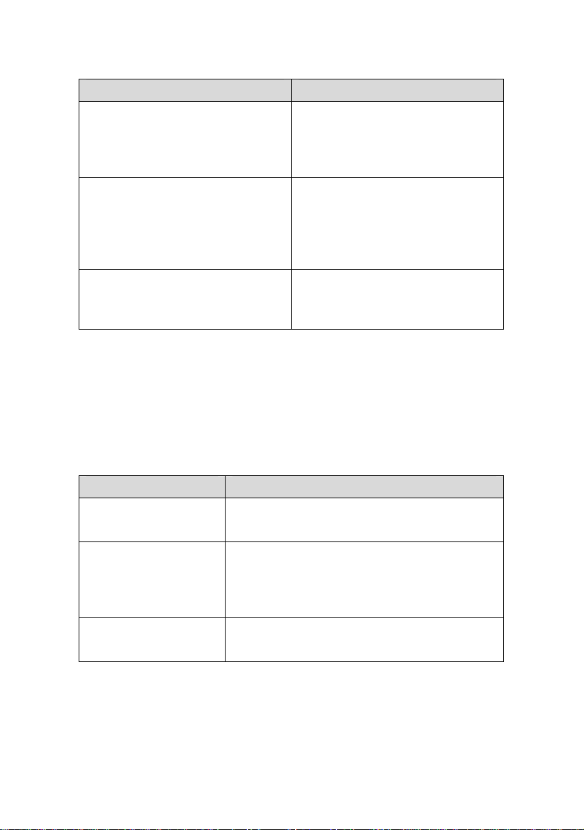
Manual Content
H3C S3100-SI Series Ethernet
Switches Operation Manual
H3C S3100-SI Series Ethernet
Switches Command Manual
H3C S3100-SI Series Ethernet
Switches Installation Manual
It is used for assisting the users
in data configurations and
typical applications.
It is used for assisting the users
in using various commands.
It is used for assisting the users
in switch installation, booting up,
hardware and software
maintenance.
Organization
H3C S3100-SI Series Ethernet Switches Quick Start is organized
as follows:
Chapter Contents
Introduces the characteristics
1 Product Overview
and technical specifications of
S3100-SI Series Ethernet
Switches.
Page 4
Chapter Contents
2 Installation Preparation
3 Installation
Introduces the installation
preparation and precaution of
S3100-SI Series Ethernet
Switches.
Introduces the procedures to
install an S3100-SI Series
Ethernet Switch, including the
setup of the mainframe, cards
and cables.
4 Lightning Protection of the
Switch
Introduces lightning protection
of S3100-SI Series Ethernet
Switches.
Conventions
The manual uses the following conventions:
I.
GUI conventions
Convention Description
< >
[ ]
/
Button names are inside angle brackets.
For example, click <OK>.
Window names, menu items, data table
and field names are inside square
brackets. For example, pop up the [New
User] window.
Multi-level menus are separated by forward
slashes. For example, [File/Create/Folder].
Page 5
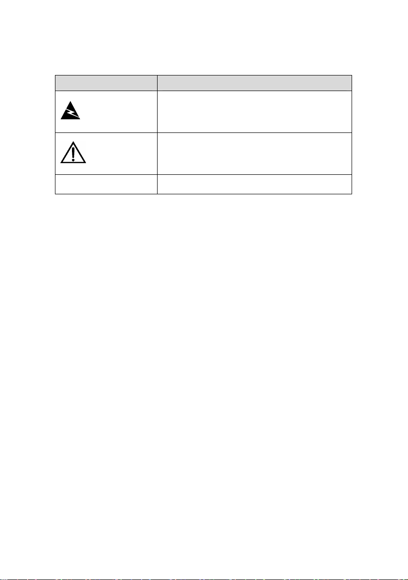
Symbols II.
Convention Description
Means reader be extremely careful.
Warning
Caution
Note Means a complementary description.
Improper operation may cause bodily
injury.
Means reader be careful. Improper
operation may cause data loss or damage
to equipment.
Environmental Protection
This product has been designed to comply with the requirement s
on environmental protection. For the proper storage, use and disposal
of this product, national laws and regulations must be observed.
Page 6

Quick Start
H3C S3100-SI Series Ethernet Switches
Table of Contents
Table of Contents
Chapter 1 Product Overview ........................................................1-1
1.1 S3100-26T-SI Ethernet Switch ..........................................1-1
1.1.1 Appearance .............................................................1-1
1.1.2 Front Panel ..............................................................1-1
1.1.3 Rear Panel...............................................................1-2
1.1.4 Power System .........................................................1-3
1.1.5 Cooling System .......................................................1-3
1.2 S3100-16T-SI Ethernet Switch ..........................................1-3
1.2.1 Appearance .............................................................1-3
1.2.2 Front Panel ..............................................................1-3
1.2.3 Rear Panel...............................................................1-4
1.2.4 Power System .........................................................1-5
1.2.5 Cooling System .......................................................1-5
1.3 S3100-8T-SI Ethernet Switch ............................................1-5
1.3.1 Appearance .............................................................1-5
1.3.2 Front Panel ..............................................................1-5
1.3.3 Rear Panel...............................................................1-6
1.3.4 Power System .........................................................1-7
1.3.5 Cooling System .......................................................1-7
1.4 S3100-26C-SI/S3100-26C-SI-DC Ethernet Switch............1-7
1.4.1 Appearance .............................................................1-7
1.4.2 Front Panel ..............................................................1-7
1.4.3 Rear Panel...............................................................1-8
1.4.4 Power System .........................................................1-9
1.4.5 Cooling System .....................................................1-10
i
Page 7

Quick Start
H3C S3100-SI Series Ethernet Switches
Table of Contents
1.5 S3100-16C-SI/S3100-16C-SI-DC Ethernet Switch..........1-10
1.5.1 Appearance ...........................................................1-10
1.5.2 Front Panel ............................................................1-10
1.5.3 Rear Panel.............................................................1-11
1.5.4 Power System .......................................................1-12
1.5.5 Cooling System .....................................................1-13
1.6 S3100-8C-SI/S3100-8C-SI-DC Ethernet Switch..............1-13
1.6.1 Appearance ...........................................................1-13
1.6.2 Front Panel ............................................................1-13
1.6.3 Rear Panel.............................................................1-14
1.6.4 Power System .......................................................1-15
1.6.5 Cooling System .....................................................1-16
1.7 S3100-SI Series Front Panel LEDs .................................1-16
1.7.1 Power LED ............................................................1-16
1.7.2 Mode LEDs and Port Status LEDs........................1-16
1.7.3 MODE button......................................................... 1-17
1.8 S3100-SI Series Technical Specifications ....................... 1-18
1.8.1 S3100-26T-SI/S3100-16T-SI/S3100-8T-SI Ethernet
Switch Technical Specifications .....................................1-18
1.8.2 S3100-26C-SI/S3100-16C-SI/S3100-8C-SI Ethernet
Switch Technical Specifications .....................................1-20
Chapter 2 Installation Preparation...............................................2-1
2.1 Precautions ........................................................................2-1
2.2 Requirements on Environment ..........................................2-2
2.2.1 Temperature/Humidity Requirements .....................2-2
2.2.2 Cleanness Requirements........................................2-3
2.2.3 Anti-interference Requirements...............................2-4
2.2.4 Laser Usage Security ..............................................2-5
2.3 Installation Tools ................................................................2-5
ii
Page 8

Quick Start
H3C S3100-SI Series Ethernet Switches
Table of Contents
Chapter 3 Installation....................................................................3-1
3.1 Installation of the Switch .................................................... 3-1
3.1.1 Mounting the Switch into a 19-Inch Cabinet............3-1
3.1.2 Mounting the Switch on a Workbench.....................3-3
3.1.3 Wall-Mount ..............................................................3-3
3.2 Installation of Expand Card................................................3-5
3.3 Connection of Power Cord and Grounding Wire ...............3-6
3.3.1 Connecting AC Power Cord ....................................3-6
3.3.2 Connecting DC Power Cord....................................3-7
3.3.3 Connecting Grounding wire..................................... 3-9
3.4 Connecting Optical Fiber .................................................3-13
3.5 Connection of Console Cable ..........................................3-14
3.5.1 Console Cable.......................................................3-14
3.5.2 Connecting Console Cable....................................3-15
3.6 Installation Verification .....................................................3-16
Chapter 4 Lightning Protection of the Switch............................4-1
4.1 Installation of Lightning Arrester for AC Power (Socket Strip
with Lightning Protection).........................................................4-1
4.2 Installation of Lightning Arrester for Network Port .............4-4
iii
Page 9
Quick Start
w
H3C S3100-SI Series Ethernet Switches
Chapter 1 Product Overvie
Chapter 1 Product Overview
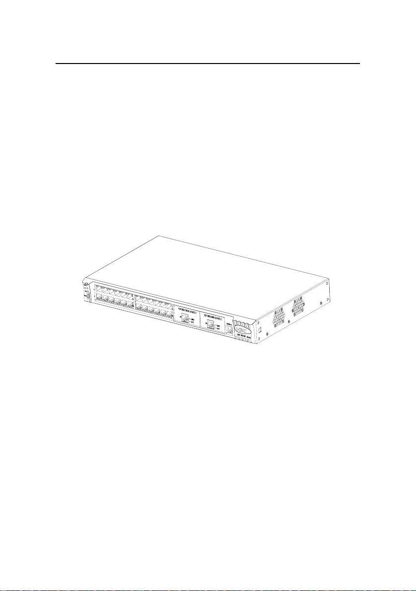
1.1 S3100-26T-SI Ethernet Switch
1.1.1 Appearance
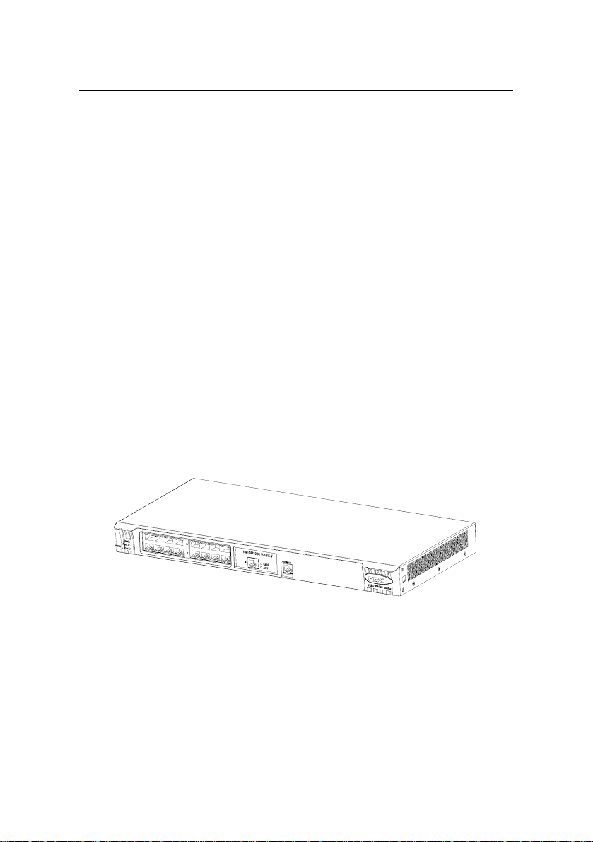
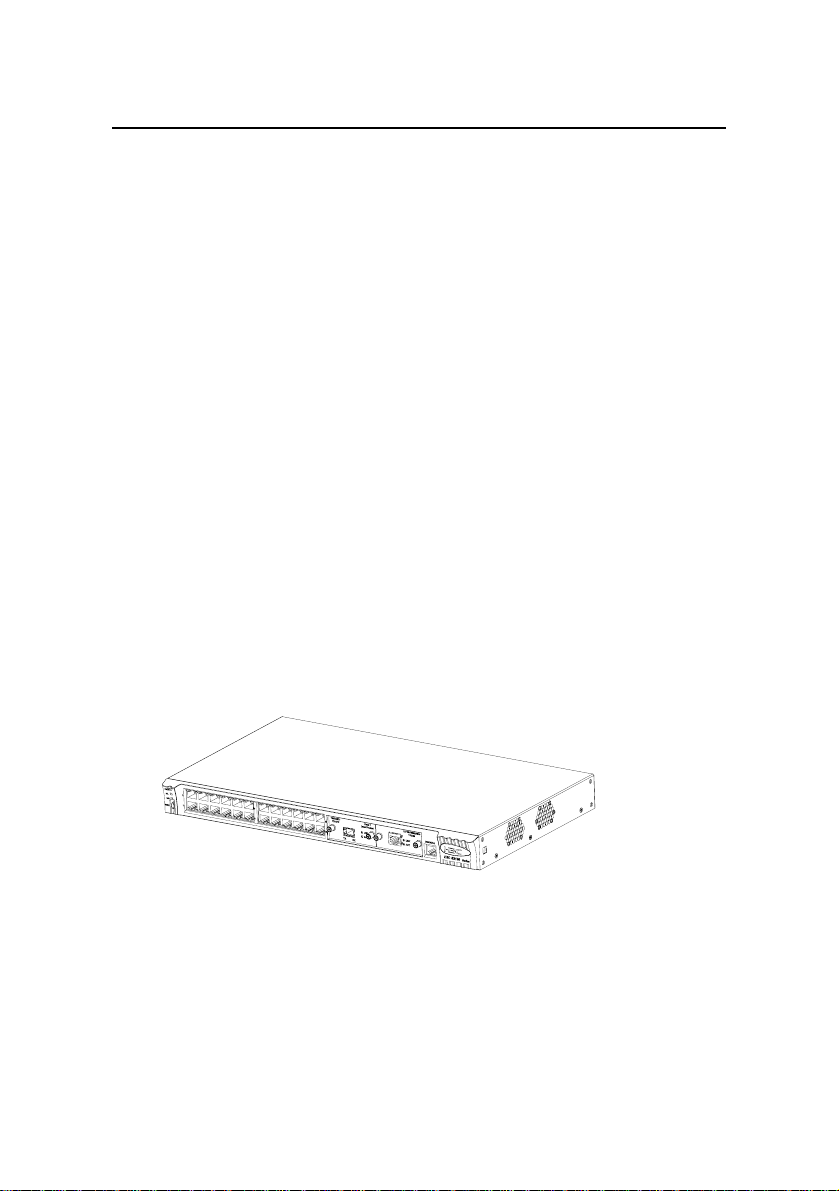
As shown in the following figure, the S3100-26T-SI Ethernet
Switch provides 24 x 10/100Base-TX Ethernet ports, two
10/100/1000Base-T Ethernet ports, and one Console port.
Figure 1-1 S3100-26T-SI Ethernet Switch
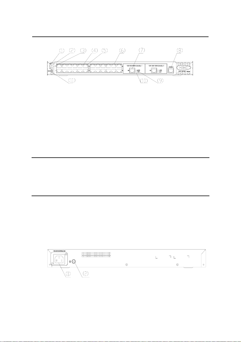
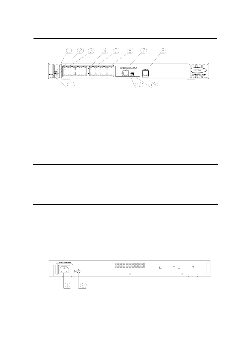
1.1.2 Front Panel
The following figure shows the front panel of the S3100-26T-SI
Ethernet Switch.
1-1
Page 10
Quick Start
w
Chapt
H3C S3100-SI Series Ethernet Switches
er 1 Product Overvie
(1) Power LED (2) A/L mode LED
(3) D/S mode LED (4) Port left LED (yellow)
(5) Port right LED (green) (6) 10/100 Base-TX port
(7) 10/100/1000 Base-T port (8) Console port
(9) Link LED (green) (10) Active LED (yellow)
(11) Mode switch button
Figure 1-2 Front panel of the S3100-26T-SI Ethernet Switch
Note:
For details about the LEDs on the front panel, refer to section 1.7
S3100-SI Series Front Panel LEDs.
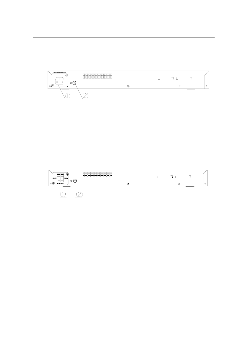
1.1.3 Rear Panel
The following figure shows the rear panel of the S3100-26T-SI
Ethernet Switch.
(1) AC power socket (2) Grounding screw
Figure 1-3 Rear panel of the S3100-26T-SI Ethernet Switch
1-2
Page 11
Quick Start
w
H3C S3100-SI Series Ethernet Switches
Chapter 1 Product Overvie
1.1.4 Power System
The S3100-26T-SI Ethernet Switch supports AC input power
module.
z Rated voltage range: 100 VAC to 240 VAC, 50/60 Hz
z Max voltage range: 90 VAC to 264 VAC, 47 Hz to 63 Hz
1.1.5 Cooling System
The S3100-SI Series Ethernet Switches (hereinafter referred to
as S3100-SI series) cool off in nature way.
1.2 S3100-16T-SI Ethernet Switch
1.2.1 Appearance
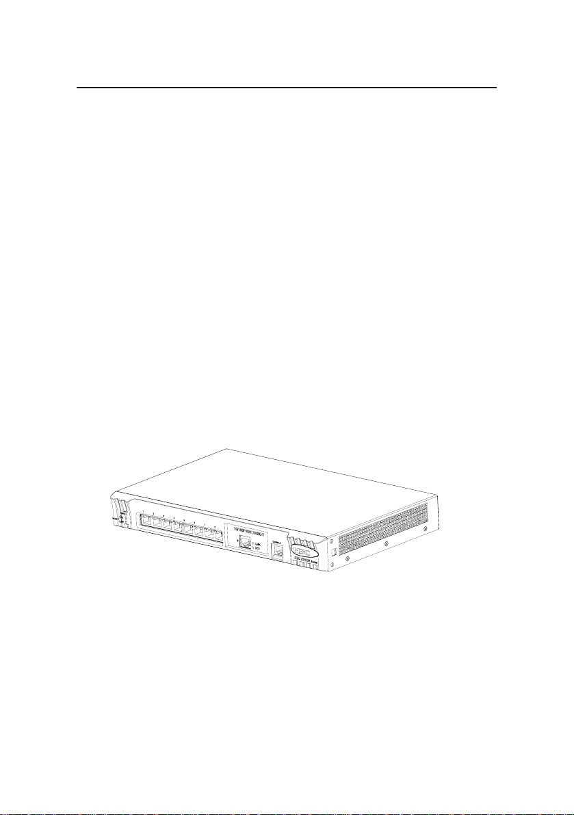
As shown in the following figure, the S3100-16T-SI Ethernet
Switch provides 16 x 10/100Base-TX Ethernet ports, one
10/100/1000Base-T Ethernet port, and one Console port.
Figure 1-4 S3100-16T-SI Ethernet Switch
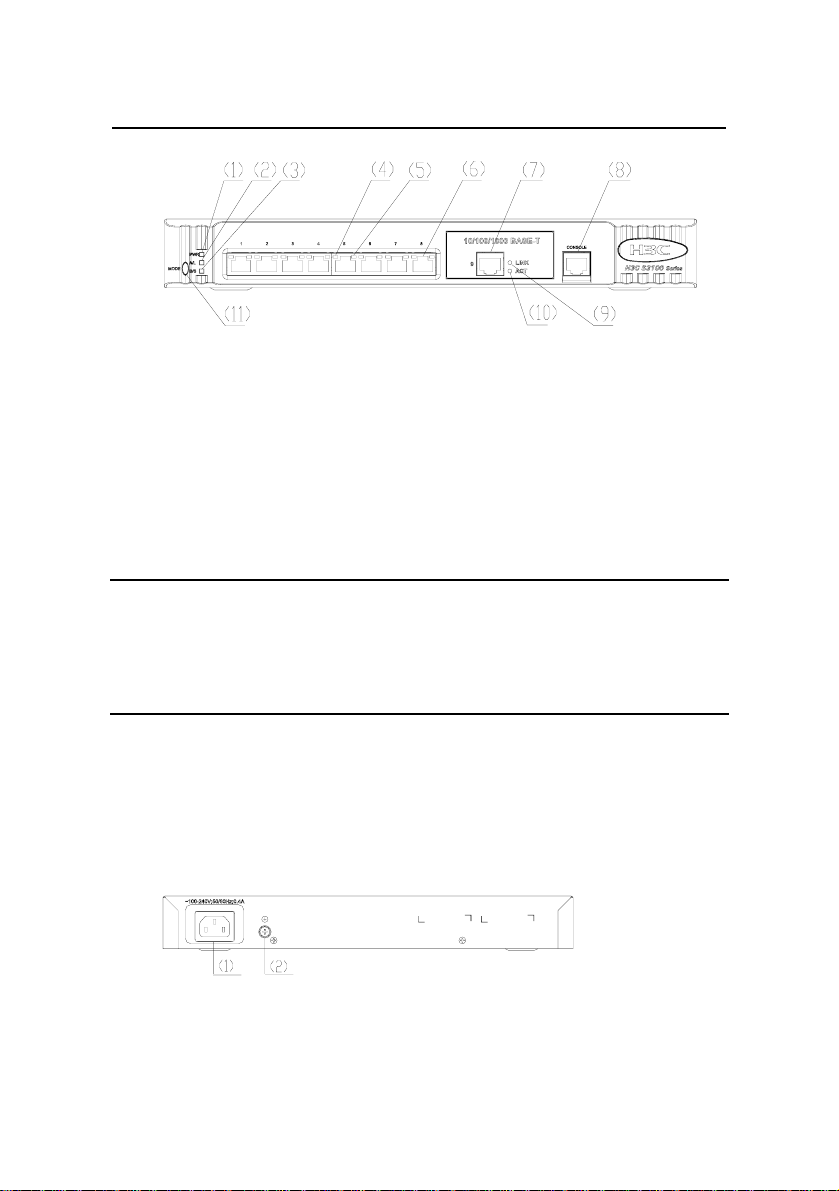
1.2.2 Front Panel
The following figure shows the front panel of the S3100-16T-SI
Ethernet Switch.
1-3
Page 12
Quick Start
w
Chapt
H3C S3100-SI Series Ethernet Switches
er 1 Product Overvie
(1) Power LED (2) A/L mode LED
(3) D/S mode LED (4) Port left LED (yellow)
(5) Port right LED (green) (6) 10/100 Base-TX port
(7) 10/100/1000 Base-T port (8) Console port
(9) Link LED (green) (10) Active LED (yellow)
(11) Mode switch button
Figure 1-5 Front panel of the S3100-16T-SI Ethernet Switch
Note:
For details about the LEDs on the front panel, refer to section 1.7
S3100-SI Series Front Panel LEDs.
1.2.3 Rear Panel
The following figure shows the rear panel of the S3100-16T-SI
Ethernet Switch.
(1) AC power socket (2) Grounding screw
Figure 1-6 Rear panel of the S3100-16T-SI Ethernet Switch
1-4
Page 13
Quick Start
w
H3C S3100-SI Series Ethernet Switches
Chapter 1 Product Overvie
1.2.4 Power System
The S3100-16T-SI Ethernet Switch supports AC input power
module.
z Rated voltage range: 100 VAC to 240 VAC, 50/60 Hz
z Max voltage range: 90 VAC to 264 VAC, 47 Hz to 63 Hz
1.2.5 Cooling System
The S3100-SI series cool off in nature way.
1.3 S3100-8T-SI Ethernet Switch
1.3.1 Appearance
As shown in the following figure, the S3100-8T-SI Ethernet
Switch provides 8 x 10/100Base-TX Ethernet ports, one
10/100/1000Base-T Ethernet port, and one Console port.
Figure 1-7 S3100-8T-SI Ethernet Switch
1.3.2 Front Panel
The following figure shows the front panel of the S3100-8T-SI
Ethernet Switch.
1-5
Page 14
Quick Start
w
Chapt
H3C S3100-SI Series Ethernet Switches
er 1 Product Overvie
(1) Power LED (2) A/L mode LED
(3) D/S mode LED (4) Port left LED (yellow)
(5) Port right LED (green) (6) 10/100 Base-TX port
(7) 10/100/1000 Base-T port (8) Console port
(9) Link LED (green) (10) Active LED (yellow)
(11) Mode switch button
Figure 1-8 Front panel of the S3100-8T-SI Ethernet Switch
Note:
For details about the LEDs on the front panel, refer to section 1.7
S3100-SI Series Front Panel LEDs.
1.3.3 Rear Panel
The following figure shows the rear panel of the S3100-8T-SI
Ethernet Switch.
(1) AC power socket (2) Grounding screw
Figure 1-9 Rear panel of the S3100-8T-SI Ethernet Switch
1-6
Page 15
Quick Start
w
H3C S3100-SI Series Ethernet Switches
Chapter 1 Product Overvie
1.3.4 Power System
The S3100-8T-SI Ethernet Switch supports AC input power
module.
z Rated voltage range: 100 VAC to 240 VAC, 50/60 Hz
z Max voltage range: 90 VAC to 264 VAC, 47 Hz to 63 Hz
1.3.5 Cooling System
The S3100-SI series cool off in nature way.
1.4 S3100-26C-SI/S3100-26C-SI-DC Ethernet Switch
1.4.1 Appearance
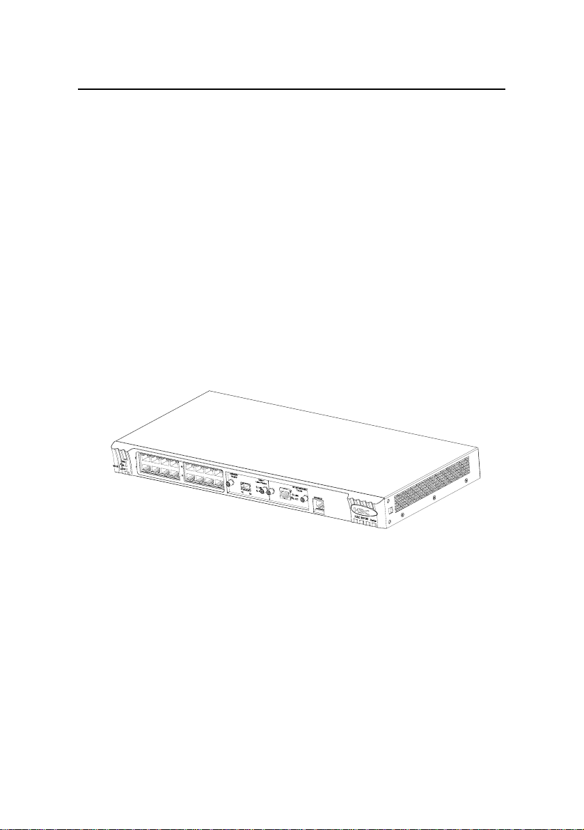
As shown in the following figure, the
S3100-26C-SI/S3100-26C-SI-DC Ethernet Switch provides 24 x
10/100Base-TX Ethernet ports, two expansion slots, and one Console
port.
Figure 1-10 S3100-26C-SI/S3100-26C-SI-DC Ethernet Switch
1.4.2 Front Panel
S3100-26C-SI and S3100-26C-SI-DC Ethernet Switch have the
same front panel,show as
Figure 1-11.
1-7
Page 16

Quick Start
w
H3C S3100-SI Series Ethernet Switches
(1) Power LED (2) A/L mode LED
(3) D/S mode LED (4) Port left LED (yellow)
(5) Port right LED (green) (6) 10/100 BASE-TX port
(7) Expansion slot (8) Console port
(9) Mode switch button
Chapter 1 Product Overvie
Figure 1-11 Front panel of the S3100-26C-SI/S3100-26C-SI-D
C
Ethernet Switch
Note:
For details about the LEDs on the front panel, refer to section 1.7
S3100-SI Series Front Panel LEDs.
1.4.3 Rear Panel
The S3100-26C-SI Ethernet Switch has two models: one
supports AC input, and another supports DC input.
1-8
Page 17
Quick Start
w
H3C S3100-SI Series Ethernet Switches
Chapter 1 Product Overvie
I. Rear panel of the S3100-26C-SI model supporting AC input:
(1) AC power socket (2) Grounding screw
Figure 1-12 Rear panel of the S3100-26C-SI model supporting
AC inp
ut
II. Rear panel of the S3100-26C-SI model supporting DC input:
(1) DC power socket (2) Grounding screw
Figure 1-13 Rear panel of the S3100-26C-SI-DC model
supporting
DC input
1.4.4 Power System
I. AC input:
z Rated voltage range: 100 VAC to 240 VAC, 50/60 Hz
z Max voltage range: 90 VAC to 264 VAC, 47 Hz to 63 Hz
II. DC input:
z Rated voltage range: –48 VDC to –60 VDC
1-9
Page 18
Quick Start
w
H3C S3100-SI Series Ethernet Switches
z Max voltage range: –36 VDC to –72 VDC
Chapter 1 Product Overvie
1.4.5 Cooling System
The S3100-SI series cool off in nature way.
1.5 S3100-16C-SI/S3100-16C-SI-DC Ethernet Switch
1.5.1 Appearance
As shown in the following figure, the
S3100-16C-SI/S3100-16C-SI-DC Ethernet Switch provides 16 x
10/100Base-TX Ethernet ports, two expansion slots, and one Console
port.
Figure 1-14 S3100-16C-SI/S3100-16C-SI-DC Ethernet Switch
1.5.2 Front Panel
S3100-16C-SI and S3100-16C-SI-DC Ethernet Switch have the
same front panel,show as
Figure 1-15.
1-10
Page 19

Quick Start
w
Chapt
H3C S3100-SI Series Ethernet Switches
er 1 Product Overvie
(1) Power LED (2) A/L mode LED
(3) D/S mode LED (4) Port left LED (yellow)
(5) Port right LED (green) (6) 10/100 BASE-TX port
(7) Expansion slot (8) Console port
(9) Mode switch button
Figure 1-15 Front panel of the S3100-16C-SI Ethernet Switch
Note:
z When a PoE card is inserted in one of the expansion slots of the
S3100-16C-SI Ethernet Switch, the switch becomes a powered
device. In this case, the other expansion slot cannot be used.
z For details about the LEDs on the front panel, refer to section 1.7
S3100-SI Series Front Panel LEDs.
1.5.3 Rear Panel
The S3100-16C-SI Ethernet Switch has two models: one
supports AC input, and another supports DC input.
1-11
Page 20

Quick Start
w
H3C S3100-SI Series Ethernet Switches
Chapter 1 Product Overvie
I. Rear panel of the S3100-16C-SI model supporting AC input:
(1) AC power socket (2) Grounding screw
Figure 1-16 Rear panel of the S3100-16C-SI model supporting
AC inp
ut
II. Rear panel of the S3100-16C-SI model supporting DC input:
(1) DC power socket (2) Grounding screw
Figure 1-17 Rear panel of the S3100-16C-SI-DC model
supporting
DC input
1.5.4 Power System
I. AC input:
z Rated voltage range: 100 VAC to 240 VAC, 50/60 Hz
z Max voltage range: 90 VAC to 264 VAC, 47 Hz to 63 Hz
II. DC input:
z Rated voltage range: –48 VDC to –60 VDC
z Max voltage range: –36 VDC to –72 VDC
1-12
Page 21

Quick Start
w
H3C S3100-SI Series Ethernet Switches
Chapter 1 Product Overvie
1.5.5 Cooling System
The S3100-SI series cool off in nature way.
1.6 S3100-8C-SI/S3100-8C-SI-DC Ethernet Switch
1.6.1 Appearance
As shown in the following figure, the S3100-8C-SI/S3100-8C-SI
-DC Ethernet Switch provides 8 x 10/100Base-TX Ethernet ports, one
expansion slot, and one Console port.
Figure 1-18 S3100-8C-SI/S3100-8C-SI-DC Ethernet Switch
1.6.2 Front Panel
S3100-8C-SI and S3100-8C-SI-DC Ethernet Switch have the
same front panel,show as
Figure 1-19.
1-13
Page 22

Quick Start
w
Chapt
H3C S3100-SI Series Ethernet Switches
er 1 Product Overvie
(1) Power LED (2) A/L mode LED
(3) D/S mode LED (4) Port left LED (yellow)
(5) Port right LED (green) (6) 10/100 BASE-TX port
(7) Expansion slot (8) Console port
(9) Mode switch button
Figure 1-19 Front panel of the S3100-8C-SI Ethernet Switch
Note:
For details about the LEDs on the front panel, refer to section 1.7
S3100-SI Series Front Panel LEDs.
1.6.3 Rear Panel
The S3100-8C-SI Ethernet Switch has two models: one supports
AC input, and another supports DC input.
1-14
Page 23

Quick Start
w
H3C S3100-SI Series Ethernet Switches
Chapter 1 Product Overvie
I. Rear panel of the S3100-8C-SI model supporting AC input:
(1) AC power socket (2) Grounding screw
Figure 1-20 Rear panel of the S3100-8C-SI model supporting
AC inp
ut
II. Rear panel of the S3100-8C-SI model supporting DC input:
(1) DC power socket (2) Grounding screw
Figure 1-21 Rear panel of the S3100-8C-SI model supporting
DC input
1.6.4 Power System
I. AC input:
z Rated voltage range: 100 VAC to 240 VAC, 50/60 Hz
z Max voltage range: 90 VAC to 264 VAC, 47 Hz to 63 Hz
II. DC input:
z Rated voltage range: –48 VDC to –60 VDC
z Max voltage range: –36 VDC to –72 VDC
1-15
Page 24

Quick Start
w
H3C S3100-SI Series Ethernet Switches
Chapter 1 Product Overvie
1.6.5 Cooling System
The S3100-SI series cool off in nature way.
1.7 S3100-SI Series Front Panel LEDs
1.7.1 Power LED
Table 1-1 Description of the power LED on S3100-SI series
LED Mark on the panel Status Description
ON
Power LED PWR
OFF
The switch is
powered on.
The switch is
powered off.
1.7.2 Mode LEDs and Port Status LEDs
The A/L mode LED and the D/S mode LED are used to indicate
the mode of the port status LEDs. Only one of the two mode LEDs is
on at one time. When the A/L mode LED is on, it implies that the port
status LEDs are indicating the Active and Link status of the
corresponding ports. When the D/S mode LED is on, it implies that the
port status LEDs are indicating the Duplex and Speed status of the
corresponding ports.
1-16
Page 25

Quick Start
w
H3C S3100-SI Series Ethernet Switches
Chapter 1 Product Overvie
Table 1-2 Description of the port status LEDs on the S3100-SI
series
Mode LED
status
A/L mode
LED is on
D/L mode
LED is on
Port status LEDs and
their status
Flashing
Yellow LED
(left)
OFF
ON
Green LED
(right)
OFF
ON
Yellow LED
(left)
OFF
ON
Green LED
(right)
OFF
Description
Data is passing through
the port.
No data is passing
through the port.
The port is connected
properly
The port is not
connected or wrongly
connected.
The port operates in full
duplex mode.
The port operates in
half duplex mode.
The port operates at
100 Mbps.
The port operates at 10
Mbps.
1.7.3 MODE button
The MODE button is a mode switch button for the status LEDs of
100 Mbps Ethernet ports. You can toggle between the A/L LED and
the D/S LED by pressing this button.
1-17
Page 26

Quick Start
w
H3C S3100-SI Series Ethernet Switches
After the switch is powered on, the A/L LED lights up initially. If
you press the MODE button, the D/S LED lights up. After that, if you
press the MODE button again within 45 seconds, the A/L LED lights up
again, or else the A/L LED automatically lights up after 45 seconds.
The MODE button is convenient for you to check the current
status of the ports as required. For example, if you want to learn the
Duplex and the Speed status of a port, you can first press the MODE
button to switch to the D/S LED, then observe the status (OFF, ON, or
flashing) of the two LEDs beside the port, and finally determine the
current status of the port according to the above table.
Chapter 1 Product Overvie
1.8 S3100-SI Series Technical Specifications
1.8.1 S3100-26T-SI/S3100-16T-SI/S3100-8T-SI Ethernet Switch Technical Specifications
Table 1-3 S3100-26T-SI/S3100-16T-SI/S3100-8T-SI Ethernet
Switch technical specifications
Item
Physical
dimensions (H x
W x D)
Weight ≤ 3.2 kg (7.1 lb)
S3100-26T-
SI
42 x 436 x
240 mm (1.7
x 17.2 x 9.4
in)
1-18
S3100-16T-SI S3100-8T-SI
42 x 436 x 200
mm (1.7 x
17.2 x 7.9 in)
42 x 326 x
200 mm (1.7
x 12.8 x 7.9
in)
Page 27

Quick Start
w
H3C S3100-SI Series Ethernet Switches
Item
S3100-26T-
SI
Chapter 1 Product Overvie
S3100-16T-SI S3100-8T-SI
Number of fixed
ports
24 x
10/100BaseTX
auto-sensing
ports
2 x
10/100/1000
Base-T ports
16 x
10/100Base-T
X
auto-sensing
ports
1 x
10/100/1000B
ase-T port
8 x
10/100BaseTX
auto-sensing
ports
1 x
10/100/1000
Base-T port
Management port One Console port
Only AC input is supported.
Rated voltage range: 100 VAC to 240 VAC,
Power supply
50/60 Hz
Max voltage range: 90 VAC to 264 VAC, 47 Hz
to 63 Hz
PoE (as powered
device)
Not
supported
Not supported
Not
supported
System power
consumption (full
20 W 12 W 10 W
load)
Fan None None None
Operating
temperature
Relative humidity
(noncondensing)
0°C to 45°C
10% to 90%
1-19
Page 28

Quick Start
w
H3C S3100-SI Series Ethernet Switches
Chapter 1 Product Overvie
1.8.2 S3100-26C-SI/S3100-16C-SI/S3100-8C-SI Ethernet Switch Technical Specifications
Table 1-4 S3100-26C-SI/S3100-16C-SI/S3100-8C-SI Ethernet
Switch technical specifications
Item S3100-26C-SI S3100-16C-SI S3100-8C-SI
Physical
dimension
(H x W x D)
42 x 436 x 240
mm (1.7 x 17.2
x 9.4 in)
Weight ≤ 3.2 kg (7.1 lb)
24 x
Number of
fixed ports
10/100Base-T
X auto-sensing
ports
Number of
expansion
2 2 1
slots
42 x 436 x 200
mm (1.7 x 17.2
x 7.9 in)
16 x
10/100Base-T
X auto-sensing
ports
42 x 326 x 200
mm (1.7 x 12.8
x 7.9 in)
8 x
10/100Base-T
X auto-sensing
ports
1-20
Page 29

Quick Start
w
H3C S3100-SI Series Ethernet Switches
Chapter 1 Product Overvie
Item S3100-26C-SI S3100-16C-SI S3100-8C-SI
10/100/1000BASE-T interface module with max
transmission distance of 100 m (328.1 feet)
100BASE-SX (SC, 2 km (1.2 mi))
100BASE-LX (SC, 15 km (9.3 mi))
100BASE-LH40 (SC, 40 km (24.9 mi))
1000BASE-SX (SC, 0.5 km (0.3 mi))
1000BASE-LX (SC, 10 km (6.2 mi))
Supported
expansion
interface
module type
1000BASE-LH40 (LC, 40 km (24.9 mi))
1000BASE-LH70 (LC, 70 km (43.5 mi))
1000BASE-STACK (not supported by
S3100-8C-SI)
100BASE-TX PD (powered device) interface
module (not supported by S3100-26C-SI)
1000Base-PX10 (SC connector, 10 km (6.2 mi))
1000Base-PX20 (SC connector, 20 km (12.4 mi))
100Base-LX-SM1310-BIDI (SC, 15 km (9.3 mi))
100Base-LX-SM1550-BIDI (SC, 15 km (9.3 mi))
Managemen
t port
Power
supply
One Console port
Both AC input switch model and DC input switch
model are available.
AC input:
Rated voltage range: 100 VAC to 240 VAC,
50/60Hz
Max voltage range: 90 VAC to 264 VAC, 47 Hz to 63
Hz
DC input:
Rated voltage range: –48 VDC to –60 VDC
Max voltage range: –36 VDC to –72 VDC
1-21
Page 30

Quick Start
w
H3C S3100-SI Series Ethernet Switches
Chapter 1 Product Overvie
Item S3100-26C-SI S3100-16C-SI S3100-8C-SI
PoE (as
powered
Not supported Supported Supported
device)
System
power
consumption
20 W 12 W 10 W
(full load)
Fan None None None
Operating
temperature
0°C to 45°C
Relative
humidity
(nonconden
10% to 90%
sing)
Note:
z Only S3100-16C-SI or S3100-8C-SI switch supports 100BASE-TX
PD interface module.
z The PoE configuration is on the remote power source device, on
the powered device (S3100-16C-SI or S3100-8C-SI), you only
need to insert the cable into the interface of 100BASE-TX PD.
z BIDI interface card must be used in couple, i.e., if the local end
uses 100Base-LX-SM1310-BIDI, the remote end needs to use
100Base-LX-SM1550-BIDI.
z An S3116C or S3126C switch can accommodate only one ONU
card (000Base-PX10/20)
1-22
Page 31

Quick Start
H3C S3100-SI Series Ethernet Switches
Chapter 2 Installation
Preparation
Chapter 2 Installation Preparation
2.1 Precautions
To avoid any device impairment and bodily injury because of
improper use, please take the following precautions:
z Before cleaning the switch, pull out the power plug of the
switch. Do not clean the switch with wet cloth or liquid.
z Do not place the switch near water or in a damp area.
Prevent water or moisture from entering the switch chassis.
z Do not place the switch on an unstable case or desk,
because the switch might be damaged severely in case of a
fall.
z Keep the switch room drafty and the switch ventilation hole
free of obstruction.
z The switch can operate normally only under correct voltage
input. Make sure that the operating voltage is consistent with
that labeled on the switch.
z To prevent electric shock, do not open the chassis while the
switch is operating, and do not open the chassis arbitrarily
even when the switch is powered off.
z Before changing interface board, wear ESD-preventive wrist
strap to prevent the board from being damaged by
electrostatic discharge.
2-1
Page 32

Quick Start
H3C S3100-SI Series Ethernet Switches
Chapter 2 Installation
Preparation
2.2 Requirements on Environment
S3100-SI series must be used indoors. When you install your
switch in a cabinet or install it directly on a workbench, you must
ensure:
z Enough space is left near the air-intake hole and the
ventilation hole of the switch for the heat dissipation of the
switch chassis.
z The cabinet or the workbench takes good ventilation and
heat dissipation system.
z The cabinet or the workbench is solid enough to bear the
weight of the switch and the accessories.
z The cabinet or the workbench is well grounded.
To ensure normal operation and to prolong the life span of the
switch, the following requirements on the installation site must also be
satisfied.
2.2.1 Temperature/Humidity Requirements
You should keep your equipment room within the proper
temperature and humidity ranges to ensure the normal operation and
working life of your switch. If the humidity in the equipment room is too
high for a long time, it may decrease the insulation attribute of
insulating material or even cause electric leakage of insulating
material, and, sometimes, may change the mechanical performance
of material and cause the rustiness and corrosion of metal parts. If the
relative humidity is too low, the captive screws may become loose due
to the shrinking of insulation washers; in addition, electrostatic is more
likely to be produced in a dry environment, which may damage the
circuit of the switch. High temperature may cause even greater
2-2
Page 33

Quick Start
H3C S3100-SI Series Ethernet Switches
Chapter 2 Installation
Preparation
damage to the switch. High temperature for a long time will speed up
the aging of insulation material, greatly lower the reliability of the
switch and greatly reduce the life span of the switch.
2.2.2 Cleanness Requirements
Dust is a potential hazard to the safe operation of the switch.
Falling on the equipment, it may cause electrostatic adsorption, and
hence result in poor contact of the metal connectors or connection
points. This is more likely to happen when the indoor relative humidity
is low; in this case, it may not only shorten the device’s working life,
but also incur communication failure. The requirements on dust
content and particle diameter in the equipment room are shown in the
following table:
Table 2-1 Requirements on dust content in the equipment room
Physical active
substance
Dust particle particle/m³
Unit Content
≤ 3 x 10
4
(No visible dust
on desk in three days)
Note: Dust particle diameter ≥ 5µm
Besides the requirements on dust, rigorous requirements are
also set on the content of chloride, acid, and sulfide in the air of the
equipment room. These kinds of harmful gas will accelerate metal
corrosion and aging of certain parts. The equipment room should be
protected from the intrusion of harmful gases such as SO
and Cl
. The limits of these kinds of harmful gas are shown in the
2
, H2S, NH3
2
following Table.
2-3
Page 34

Quick Start
H3C S3100-SI Series Ethernet Switches
Table 2-2 Limits on harmful gas in the equipment room
Gas Max content (mg/m³)
Chapter 2 Installation
Preparation
SO
H2S
NH
Cl
2
2
3
0.2
0.006
0.05
0.01
2.2.3 Anti-interference Requirements
A switch in use may be affected by the interference from outside
the system by way of capacitance coupling, inductance coupling,
electromagnetic radiation, public impedance (including the grounding
system) coupling or conducting line (power line, signaling line and
transmission line etc.). Therefore, you should pay attention to the
following:
z If AC supply system is TN system, AC power socket should
be a single-phase three-line power socket with Protection
Earth (PE) so that the filter circuit on the equipment can
effectively filter out the interference coming from the power
supply system.
z Keep the switch far away from high-power radio transmitters,
radars, and high-frequency heavy-current devices.
z Adopt electromagnetic shielding measure if necessary. For
example, you can adopt shielded interface cable.
z Wire interface cables indoors. Do not wire cables outdoors
in case that overvoltage and overcurrent damage the
device.
2-4
Page 35

Quick Start
H3C S3100-SI Series Ethernet Switches
Chapter 2 Installation
Preparation
2.2.4 Laser Usage Security
S3100-SI series are category-1 laser equipment.
When an optional optical interface card of the S3100-SI series is
operating, it is prohibited to stare into the optical interface because the
laser beam emitted from the optical fiber takes high energy and may
hurt your retina.
Caution:
Staring at the laser beam inside the fiber could hurt your eyes.
2.3 Installation Tools
z Phillips screwdriver
z Flat-blade screwdriver
z ESD-preventive wrist strap
Caution:
These installation tools are not shipped with S3100-SI series. You will
have to prepare them beforehand.
2-5
Page 36

Quick Start
H3C S3100-SI Series Ethernet Switches
Chapter 3 Installation
Chapter 3 Installation
Caution:
On a mounting screw of the chassis of any H3C Series Switches,
there is a seal which must be kept intact before the agent maintains
the switch for you. You must get the permission of your local agent
before you can open the chassis. Otherwise, you will be responsible
for irreversible damages caused by your operations.
3.1 Installation of the Switch
3.1.1 Mounting the Switch into a 19-Inch Cabinet
Follow these steps to mount your switch into a 19-inch standard
cabinet:
Step 1: Check the grounding and stability of the cabinet. Install a
mount ear on each side of the front panel of the switch with screws.
Caution:
Use long mount ears when installing the S3100-8T-SI or S3100-8C-SI
Ethernet Switch. (The long mount ears are optional components).
3-1
Page 37

Quick Start
H3C S3100-SI Series Ethernet Switches
Chapter 3 Installation
Step 2: Place the switch on a shelf of the cabinet, and slide the
switch into the cabinet along the guides in the cabinet to an
appropriate position.
Step 3: Insert screws through the mount ears into the front
mounting posts of the cabinet and tighten them, ensuring the switch is
fixed steadily in the cabinet.
Figure 3-1 Mounting the switch into a 19-inch cabinet
Note:
The mount ears are used for fixing instead of weight bearing. In a
19-inch standard cabinet, the switch is supported by the shelf beneath
it.
3-2
Page 38

Quick Start
H3C S3100-SI Series Ethernet Switches
Chapter 3 Installation
3.1.2 Mounting the Switch on a Workbench
When a 19-inch standard cabinet is not available, you can simply
place the switch on a clean workbench. When doing so, you should
ensure:
z The workbench is stable and well grounded.
z A clearance of about 10 cm is reserved around the switch for
heat dissipation.
z No heavy object is placed on the switch.
z The S3100-SI series are designed with no fan. Therefore,
you should install them in a drafty environment, and keep at
least 1.5 cm vertical distances between the neighboring
devices if you need to stack the switches one upon another.
3.1.3 Wall-Mount
You can hang the S3100-8T-SI and S3100-8C-SI Ethernet
Switches against walls.
The wall can be made of cement, wood, or drywall.
Figure 3-2 and Figure 3-3 shows the recommended sizes (in mm)
of the screws and anchor kits used for mounting:
Figure 3-2 Screw
3-3
Page 39

Quick Start
H3C S3100-SI Series Ethernet Switches
Figure 3-3 Anchor kit illustration
Chapt
er 3 Installation
The wall-mount procedure is as follows (see
Figure 3-4):
1) Drill two holes in the wall on the same horizontal line, with a
distance of 169 mm.
2) Insert anchor kits into the holes.
3) Drive the screws into the anchor kits, keeping the screws 1.5
mm out of the wall.
Figure 3-4 Wall-mount illustration
4) Aiming at the two screws, hook the two mounting holes of
the switch on the screws.
3-4
Page 40

Quick Start
H3C S3100-SI Series Ethernet Switches
Chapter 3 Installation
Caution:
When mounting the switch, keep the Ethernet ports of the switch
facing downwards and the two sides with ventilation holes vertical to
the ground.
3.2 Installation of Expand Card
Note:
The following section describes the procedures to install an ONU card.
The procedures also apply to the installation of other cards.
I. Appearance
Figure 3-5 An ONU card
Captive screwCaptive screw
3-5
Page 41

Quick Start
H3C S3100-SI Series Ethernet Switches
II. Installation of an ONU subcard
Step 1: Dismount the dummy panel of an expansion slot of the
switch.
Step 2: Insert the ONU card into the expansion slot to the place.
Step 3: Fix the ONU card firmly with captive screws.
Chapter 3 Installation
3.3 Connection of Power Cord and Grounding Wire
3.3.1 Connecting AC Power Cord
I. AC power socket (recommended)
You are recommended to use a mono-phase three-wire power
socket with a neutral point or a multi-function power socket for
computers. The neutral point of the power in your building must be
well grounded. Normally, the neutral point of the power supply system
in your building has already been grounded during the construction
and wiring; but you should make sure this is the fact.
Neutral point
Neutral point
Live line
Zero line
Zero line
Figure 3-6 Recommended AC power socke
Live line
3-6
t
Page 42

Quick Start
H3C S3100-SI Series Ethernet Switches
Chapter 3 Installation
II. Connecting AC power cord
Step 1: Connect one end of the chassis grounding wire (coming
with the switch) to the grounding screw on the rear of the chassis and
the other end to the ground nearby.
Step 2: Connect one end of the power cord to the power socket
on the rear panel of the chassis and the other end to an outside AC
power socket.
Step 3: Check whether the PWR LED on the front panel of the
switch is ON. If the LED is ON, it shows the power cord is properly
connected.
Caution:
Before powering on the switch, you should properly connect the
grounding wire.
3.3.2 Connecting DC Power Cord
(1) DC power input. NEG (-): –48V; RTN (+): –48V working ground
(2) Grounding screw
Figure 3-7 DC power socket
3-7
Page 43

Quick Start
H3C S3100-SI Series Ethernet Switches
Chapter 3 Installation
Step 1: Connect one end of the chassis grounding wire (coming
with the switch) to the grounding screw on the rear of the chassis and
the other end to the ground nearby.
Step 2: Connect the DC power terminals of the switch to –48 VDC
power supply through DC power cords, with NEG (-) connected to the
–48V output and RTN (+) connected to the working ground of the –48
VDC power supply.
Note:
To connect the power cord to the DC power terminals on the chassis,
loosen the screws on the terminals first, insert the connectors of the
power cord into the terminals, and tighten the screws.
Step 3: Check whether the PWR LED on the front panel of the
switch is ON. If the LED is ON, it shows the power cord is properly
connected.
Caution:
Before powering on the switch, you should properly connect the
grounding wire.
3-8
Page 44

Quick Start
H3C S3100-SI Series Ethernet Switches
Chapter 3 Installation
3.3.3 Connecting Grounding wire
Caution:
You should properly connect the switch grounding wire since it is
crucial to the lightning protection and electromagnetic shield (EMS) of
your switch.
The power input end of the switch is connected with a noise filter,
whose central ground is directly connected to the chassis, forming the
so-called chassis ground (commonly known as PGND). This chassis
ground must be securely connected to the earth so that the faradism
and leakage electricity can be safely released to the earth, enhancing
the EMS capability of the switch.
Ground your switch as follows:
z When a grounding strip is available at the installation site,
attach one end of the yellow-green grounding wire of the
switch to the grounding screw on the grounding strip and
fasten the captive nut. (Note that the fire main and lightning
rod of your building are not suitable for grounding the switch.
The grounding wire of the switch should be connected to the
construction engineering ground of the equipment room.)
3-9
Page 45

Quick Start
H3C S3100-SI Series Ethernet Switches
Chapter 3 Installation
(2 )
(2 )
(3)
(3)
(3)
(3)
(1 )
(1 )
(1 )
(1 )
(1 )
(1 )
(1 )
(1 )
(4)
(4)
(4)
(4)
(4)
(4)
(4)
(4)
(1) Power input (2) Grounding screw
(3) Grounding wire (4) Grounding strip
Figure 3-8 Grounding the switch through a grounding strip
z When there is no grounding strip but there is cement floor
nearby where a grounding body is allowed to be buried,
hammer an angle steel/steel pipe no shorter than 0.5 m into
the earth, with the yellow-green grounding wire of the switch
welded onto the angle steel/steel pipe and the jointing point
being processed against erosion.
(2)
(2)
(2)
(2)
(3 )
(3 )
(3 )
(3 )
(1)
(1)
(1)
(1)
(5 )
(5 )
(5 )
(5 )
(4 )
(4 )
(4 )
(4 )
(1) Power input (2) Grounding screw
(3) Grounding wire (4) Earth
(5) Angle steel
3-10
Page 46

Quick Start
H3C S3100-SI Series Ethernet Switches
Chapter 3 Installation
into the earth
z For an AC-powered switch, if none of the above two
conditions is available, ground it through the PE wire of the
AC power supply. In this case, make sure this PE wire is well
connected to the ground at the power distribution room or
AC transformer.
(1)
(1)
(3)
(3)
(3)
(3)
(2)
(2)
(2)
(2)
(6)
()
(6)
()
(5)
(5)
(5)
(4)
(4)
(4)
(4)
(1) AC power input (2) Grounding screw
(3) Power transformer (4) PE wire
(5) 3-wire cable for AC power input (6) Ethernet switch
(5)
y Figure 3-9 Grounding the switch by burying the grounding bod
Figure 3-10 Grounding the switch through AC PE wire
z For a DC-powered switch (–48 VDC), if none of the first two
conditions is available, ground it through the return wire
(RTN) of the DC power supply. In this case, make sure this
RTN wire is well connected to the ground at the DC output of
the DC power cabinet.
3-11
Page 47

Quick Start
Chapt
H3C S3100-SI Series Ethernet Switches
er 3 Installation
(1)
(1)
(1)
(1)
(11)
(11)
(11)
(11)
(2)
(2)
(2)
(2)
(4)
(4)
(4)
(4)
(6)
(6)
(6)
(6)
(3)
(3)
(3)
(3)
(5)
(5)
(5)
(5)
(7)
(7)
(7)
(7)
(8)
(8)(8)
(8)
(8)(8)
(9)
(9)
(10)
(10)
(1)AC/DC power cabinet (2) –48V strip (3) –48V
(4) RTN strip (5) RTN (6) PGND strip
(7) Grounding to the earth (8) Grounding wire (9) screw
(10) Ethernet switch (11) DC power input
Figure 3-11 Grounding the switch through the PGND of the
power ca
binet
3-12
Page 48

Quick Start
H3C S3100-SI Series Ethernet Switches
Chapter 3 Installation
3.4 Connecting Optical Fiber
Caution:
z After a switch starts, the PON interface may emit invisible radial
when there is no optical connector connected to it and the
protective cap is removed from it. Therefore, do not stare into the
optical interface.
z Be sure to cover the protective cap within 10 seconds if an optical
connector is not in use to keep the optical connector clean.
z Be sure to cover the protective cap if a PON interface has no
optical connector attached.
z Place the protective caps in a safe place when a PON interface has
fiber connected to prepare for the cases the fiber is pulled out.
Note:
The following section describes the procedures to connect optical fiber
to an ONU card. The procedures also apply to other subcards.
Step 1: Remove the protective cap from the optical connector of
the fiber.
Step 2: Remove the protective cap from the PON interface of the
ONU card.
3-13
Page 49

Quick Start
H3C S3100-SI Series Ethernet Switches
Step 3: Plug the optical connector into the PON interface of the
ONU subcard.
Chapter 3 Installation
3.5 Connection of Console Cable
3.5.1 Console Cable
Console cable is an 8-core shielded cable. At one end of the
cable is a crimped RJ45 connector to be connected to the Console
port of the switch; at the other end of the cable is a DB-9 (female)
connector to be connected to the 9-core (pin) serial port on the
Console terminal. See the following figure.
Figure 3-12 Console cable
Table 3-1 Console cable connector pinouts and mapping relation
RJ-45 Signal Direction DB-9
1 RTS ← 7
2 DTR ← 4
3 TXD ← 3
4 CD → 1
5 GND - 5
6 RXD → 2
3-14
Page 50

Quick Start
H3C S3100-SI Series Ethernet Switches
Chapter 3 Installation
RJ-45 Signal Direction DB-9
7 DSR → 6
8 CTS → 8
3.5.2 Connecting Console Cable
Follow these steps to connect a terminal device, a PC for
example, to the switch:
Step 1: Connect the DB-9 female connector of the Console cable
to the serial port of the PC or the terminal device used to configure the
switch.
Step 2: Connect the RJ-45 connector of the Console cable to the
Console port of the switch.
Caution:
Identify the label of the port before connecting a connector.
3-15
Page 51

Quick Start
H3C S3100-SI Series Ethernet Switches
Chapter 3 Installation
Note:
When connecting a PC to a powered-on switch, you are
recommended to connect the DB-9 connector of the Console cable to
the PC before connecting the RJ45 connector to the switch. When
disconnecting a PC from a powered-on switch, you are recommended
to disconnect the DB-9 connector of the Console cable from the PC
after disconnecting the RJ45 connector from the switch.
3.6 Installation Verification
After completing the installation, check that:
z The correct power is used.
z The grounding wire is connected.
z Both Console cable and power cord are properly connected.
z All the interface cables are wired indoors. If there is any
cable wired outdoors, verify that socket strip with lightning
protection and lightning arresters for network ports have
been properly connected.
3-16
Page 52

Quick Start
H3C S3100-SI Series Ethernet Switches
Chapter 4 Lightning Protection
of the Switch
Chapter 4 Lightning Protection of the
Switch
4.1 Installation of Lightning Arrester for AC Power (Socket Strip with Lightning Protection)
Caution:
Lightning arrester will not be shipped with the switch. You should
purchase it by yourself if needed.
If an outdoor AC power cord should be directly led to the switch,
please serially connect the lightning arrester for AC power (Socket
Strip with Lightning Protection) before you plug AC power cord into the
switch, thus to prevent the possible damage to the switch due to
lightning strike. You can use cable clips and screws to fasten the
lightning arrester for AC power on the cabinet, workbench or the wall
of equipment room.
4-1
Page 53

Quick Start Chapter 4 Lightning Protection
H3C S3100-SI Series Ethernet Switches
of the Switch
Grounding and polarity indicator (red) :
On m eans that the lines are wrongly connected
(either the ground wire is not well connected, or the live and zero lines are wrongly connected).
Please check the power supply circuit.
r switch
Powe
Norm al operation indicator (green):
On m eans that the arrester works normally. Otherwise, it
means that the protection circuit has been dam aged.
Pow er socket (complied w
connected to the power
through power cord
Mainboard
ith IEC standard),
supply of the equipment room
Mu ltipurpose power socket, connected to the device
protected by the arrester
Figure 4-1 Diagram of lightning arrester
4-2
Overload auto pr
which can be ma
otector,
nually reset.
Page 54

Quick Start
H3C S3100-SI Series Ethernet Switches
Chapter 4 Lightning Protection
of the Switch
Caution:
z Make sure that the arrester is well grounded before using the
lightning arrester for power.
z After inserting AC power cord plug of switch into the socket of
lightning arrester, if the green LED is on and the red LED does not
alarm, it means that the lightning arrester of power is running and
the function of lightning protection has taken effect.
z Pay adequate attention if the red LED is on. You should correctly
locate the problem, whether it is caused because the ground wire
of the arrester is not well grounded or because the live and zero
wires are connected in reverse direction. You may check that in the
following way. When the red LED is on, use a multimeter to
examine polarity at the power socket of the arrester. If it is same to
that of the power socket in the equipment room, it means that
arrester is not well grounded. If it is adverse to that of the power
socket in the equipment room, it means that the power socket of
the arrester is set to the reverse polarity. In this case, you should
open the power socket of arrester to correct polarity. After that, if
the red LED still alarms, it means that the arrester is not well
grounded yet.
4-3
Page 55

Quick Start
H3C S3100-SI Series Ethernet Switches
Chapter 4 Lightning Protection
of the Switch
4.2 Installation of Lightning Arrester for Network Port
Note:
Lightning arrester for network port is specially designed for the
Ethernet port of 10/100M electrical interface (RJ-45 connector is
adopted in this case).
Caution:
Lightning arrester for network port will not be provided along with the
switch, and you should purchase it by yourself if needed.
If an outdoor network cable should be led to the switch, please
serially connect the lightning arrester for network port before you plug
this cable into the interface on the switch, in case of the possibility that
the switch may be damaged due to lightning strike.
I. Required tools
z Phillips screwdriver or Flat-blade screwdriver
z Multimeter
z Tilted wire cutter
4-4
Page 56

Quick Start
H3C S3100-SI Series Ethernet Switches
Chapter 4 Lightning Protection
of the Switch
II. Installation procedure
Step 1: Tear the protection paper at one side of the double faced
adhesive tape apart from the tape, and stick the tape on the surface of
the arrester. Tear the protection paper at another side apart from the
tape, and stick the arrester onto the chassis of the switch. The arrester
should be attached on the chassis as close to the grounding screw as
possible.
Step 2: According to the distance to the grounding screw of the
switch, cut the ground wire of the arrester, and securely tightening its
ground wire to the grounding screw of the switch.
Step 3: Use the multimeter to measure whether the ground wire
of the arrester contacts well with the grounding screw of chassis.
Step 4: According to the instruction of arrester for network port,
connect the arrester with switch by the cables (be carefully with the
cable direction. Outdoor network cable should be inserted into the
arrester‘s IN end, and the cable connected to the switch should be
inserted into the arrester’s OUT end). When you do that, observe
whether the arrester indicators normally display.
Note:
The instruction of lightning arrester for network port contains the
technical specifications, installation and maintenance guide of the
arrester. Please carefully read it before installing the arrester.
Step 5: Use the nylon ties to bundle the cables neatly.
4-5
Page 57

Quick Start Chapter 4 Lightning Protection
H3C S3100-SI Series Ethernet Switches
of the Switch
Network cable indoors
Switch
Power input
Network cable led i
Lightning arrester f
(attached onto th
Ground wire of light
Grounding screw
Metal cabinet th
nto from outdoor
or network port
e chassis)
ning arrester
of switch
at contains the switch
Figure 4-2 Installation diagram of lightning arrester for network
port
III. Installation precautions
Fully consider the following items in the installation process,
otherwise, the pe
will be aff
ected:
Lightning arrester for network port is installed in reverse
z
rformance of the lightning arrester for network port
direction. In practice, the “IN” end should be connected to
the outdoor network
cable and the “OUT” end to the network
port on the switch.
z
Lightning arrester for the network port is not well grounded.
The ground wire for the arrester should be as short as
possible, so to ensure its good contact with the grounding
screw of the switch.
After the connection, use the multimeter
to confirm that.
z
The lightning arrester for the network port is not installed
completely. If the switch has more than one network ports to
4-6
Page 58

Quick Start
H3C S3100-SI Series Ethernet Switches
interconnect with other devices via cables outdoor, you
should install lig
htning arresters for all these network ports
for protection.
Chapter 4 Lightning Protection
of the Switch
4-7
 Loading...