

Hangzhou Grow GM65-S User Manual
GM65-S Bar Code Reader Module
User Manual
Hangzhou Grow Technology Co., Ltd.
V1.2 Dec. 2019

Catalog
1. Introduction of Module.............................................................................................................................................3
1.1 Introduction.....................................................................................................................................................3
1.2 Technical Specification...................................................................................................................................3
1.3 Dimension(mm).............................................................................................................................................. 1
1.4 Data Interface..................................................................................................................................................3
1.5 Setup Code......................................................................................................................................................5
1.6 Save and Cancel..............................................................................................................................................5
1.7 Reset................................................................................................................................................................5
2 Communication interface...........................................................................................................................................6
2.1 Series Communication Interface.................................................................................................................... 6
2.2 USB Interface..................................................................................................................................................7
2.3 USB Virtual Serial Port...................................................................................................................................8
3 Read Mode.................................................................................................................................................................9
3.1 Continuous Mode............................................................................................................................................9
3.2 Induction Mode.............................................................................................................................................10
3.3 Manual Mode................................................................................................................................................12
3.4 Command Triggered Mode...........................................................................................................................13
4 Read Area.................................................................................................................................................................15
4.1 Full Width Area.............................................................................................................................................15
4.2 Central Area only..........................................................................................................................................15
5 Lighting and Collimate............................................................................................................................................ 17
5.1 Lighting.........................................................................................................................................................17
5.2 Collimation................................................................................................................................................... 17
6 Prompts.................................................................................................................................................................... 18
6.1 Prompts Tone................................................................................................................................................ 18
6.2 Read code successfully tone.........................................................................................................................19
6.3 Decoding Prompt.......................................................................................................................................... 19
6.4 Data Code Format.........................................................................................................................................19
6.5 Keyboard Settlement.................................................................................................................................... 20
6.6 Image Flip.....................................................................................................................................................21
6.7 Image Flip.....................................................................................................................................................21
7 Data Edition............................................................................................................................................................. 22
7.1 Prefix.............................................................................................................................................................22
7.2 Suffix.............................................................................................................................................................23
7.3 CODE ID...................................................................................................................................................... 23
7.4 Tail.................................................................................................................................................................26
7.5 Cut out Data..................................................................................................................................................26
7.6 RF Information............................................................................................................................................. 28
7.7 Output Protocol.............................................................................................................................................29
8 Bar code type enables/disable configuration...........................................................................................................30
8.1 All types of bar code can be decoded........................................................................................................... 30
8.2 Bar code rotate..............................................................................................................................................30
1

8.3 EAN13.......................................................................................................................................................... 30
8.4 EAN8............................................................................................................................................................ 31
8.5 UPCA............................................................................................................................................................31
8.6 UPCE0.......................................................................................................................................................... 32
8.7 UPCE1.......................................................................................................................................................... 32
8.8 Code128........................................................................................................................................................ 33
8.9 Code39.......................................................................................................................................................... 33
8.10 Code93........................................................................................................................................................ 34
8.11 CodeBar...................................................................................................................................................... 35
8.12 QR...............................................................................................................................................................35
8.13 Interleaved 2 of 5........................................................................................................................................ 35
8.14 Industrial 25................................................................................................................................................ 36
8.15 Matrix 2 of 5............................................................................................................................................... 37
8.16 Code11........................................................................................................................................................ 37
8.17 MSI............................................................................................................................................................. 38
8.18 RSS............................................................................................................................................................. 39
8.19 DM.............................................................................................................................................................. 39
8.20 PDF417....................................................................................................................................................... 40
9 Serial Port Instruction.............................................................................................................................................. 41
9.1 CRC Algorithm.............................................................................................................................................41
9.2Read Zone Bit................................................................................................................................................ 42
9.3Write Zone Bit............................................................................................................................................... 43
9.4Save zone bit to EEPROM Command...........................................................................................................45
9.5Zone Bit Reset To Defaults............................................................................................................................46
9.6Program Erasure Operation........................................................................................................................... 46
9.7List of zone bit............................................................................................................................................... 48
10 Appendix A:Common serial port instruction......................................................................................................63
11 Appendix B:Code ID List................................................................................................................................... 64
12 Appendix C:ASCII..............................................................................................................................................65
13 Appendix D:Data code........................................................................................................................................70
14 Appendix E:Save or Cancel................................................................................................................................ 72
2
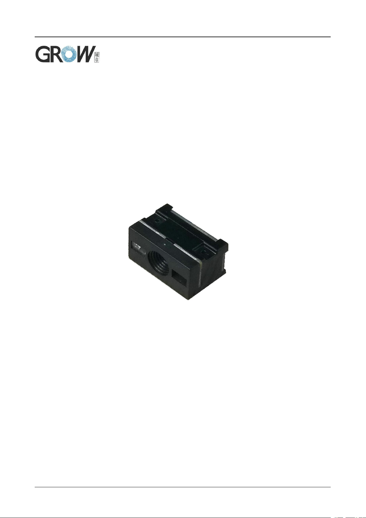
1. Introduction of Module
MG65-S Bar code reader module is a high performance
scanner, can read 1D bar code easily and read 2D bar code
with high speed. It also wins high scan speed for linear code,
even for bar code on paper or screen.
MG65-S bar code reader module is an advanced bar
code decoding algorithm which developed on image
recognition algorithm, can easily and accurately read bar
code, simplify secondary development.
MG65-S works stable in dark and large temperature
Default scan mode
Continuous scan
Read code time for once
3s
Parameter:0.1-25.5s; step-size: 0.1s; 0
means no time limited
Reading interval
1S
Parameter:0.1-25.5s; step-size: 0.1s; 0
means no time limited
Output
GBK
GBK、UNICODE、 BIG5
Interface
USB
USB 、UART、USB VCom
Interface
( TTL-232)
Serial Baud Rate
9600
adjustable,details at 2.1
Verification
N
Data bit
8
Stop bit
1
CTSRTS
No
serial mode
Read code time
for once
5s
Parameter:0.1-25.5s; step-size: 0.1s; 0
means no time limited
1.1 Introduction
range.
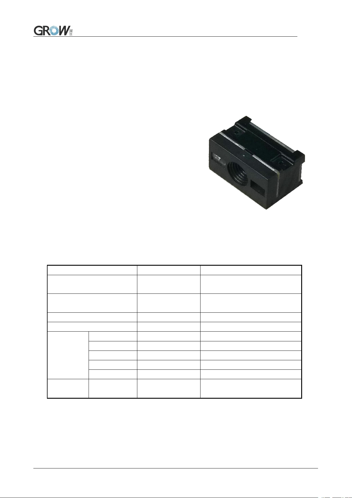
1.2 Technical Specification
3

Electrical specification:
1
Operating Voltage
DC 4.2 - 6.0V
2
Standby Current
30mA
3
Operating Current
160mA
4
Sleep Current
3mA
1
Light
White light
2
Capture light
Red
3
Scan Angle
Roll:0-360°, Pitch:±65°, Yaw:±60°
4
Resolution
648x 488
5
Scanning angle
35°(Inclination), 28°(Elevation)
1
Weight
7g
2
Size
21.4*13.5*11.8mm
Running characteristic
Physics specification:
1.3 Dimension(mm)
1
Scan Area (testing in office (250 lux)
Type of Bar
Code
Density
Min.
distance
Max. distance
Code 39
0.125 mm
(5 mils)
4.0 cm
9.0 cm
0.375 mm
(15 mils)
4.0 cm
25.0cm
UPC/EAN
0.375 mm
(15 mils)
4.0 cm
25.0cm
Code93
0.254 mm
(10 mils)
4.0 cm
21.0cm
2
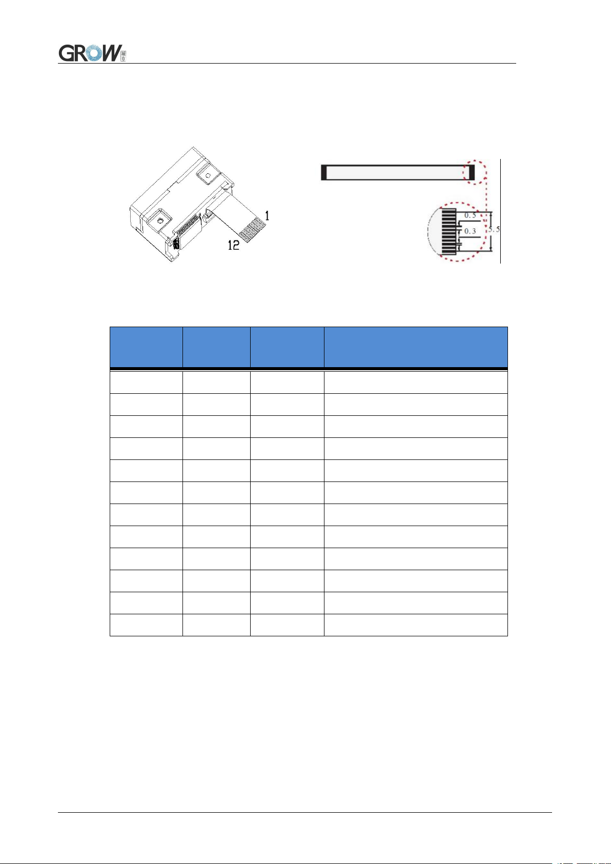
1.4 Data Interface
PIN
Input/Out
put
Definition
Remark
PIN 1
-
NC
/
PIN 2
Power
VCC
DC3.3V
PIN 3
GND
GND
PIN 4
IN
RX
PIN 5
OUT
TX
PIN 6IND-
PIN 7
OUT
D+
PIN 8
-
NC
PIN 9
OUT
BEEPER
Connected to passive buzzer
PIN10
OUT
DLED
Indicator for decoding successfully
PIN11
-
NC
PIN12
IN
TRIG
Low level triggers decoding
3
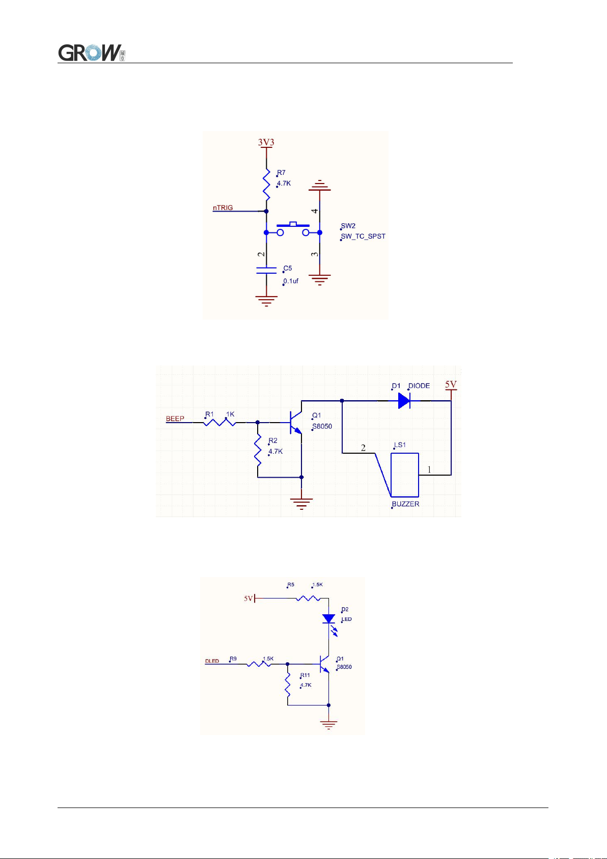
Ref. circuit diagrams:
Circuit diagram for triggering PIN 12:
Circuit diagram for pin 9(passive buzzer):
Circuit diagram for PIN 10(DLED):
4

1.5 Setup Code
Customer can set module by scan setup code.
Default: setup code on Off
Output details in setup code
Default: Not output Output
1.6 Save and Cancel
Scan cancel code to cancel wrong read date.
Save Cancel last byte
Cancel all read bytes Cancel changes
1.7 Reset
Back to Factory Setting by scan follow code.
Reset
5
2 Communication interface
Parameters
Default
Series communication interface
Standard TTL-232
Baud rate
9600
Verification
N
Data bit
8
Stop bit
1
CTSRTS
N
GM65-S can receive database, control module and set functional parameter by TTL - 232.
2.1 Series Communication Interface
It’s default and common to connect module and mainframe(such as PC, POS) by series
communication interface. Make sure communication parameter for module and mainframe are same,
then it will communicate smooth and correctly.
Series Output
TTL-232 is used for series interface which suitable for most system. Required change-over circuit
for RS-232.
Default Parameter as formForm 2- 1. Only Baud Rate can be changed.
Form 2- 1 Default Parameters
Baud Rate Settlement
1200bps 4800bps 9600bps(Default)
14400bps 19200bps
6
38400bps 57600bps 115200bps
2.2 USB Interface
Scan the following code to become standard keyboard input pattern when module connects PC by
USB.
USB PC Keyboard
Scan the following code to modify the PC access cycle for HID devices.
*1ms 3ms
5ms 10ms
Modify the interval between the device from a valid message to a released message by scanning
the following setup code.
*0ms 1ms 5ms
7
10ms 15ms
Modify the interval between the device from releasing message to the next valid message by
scanning the following setup code.
*0ms 1ms 5ms
10ms 15ms
Modify the state of the CapsLock when it prints by scanning the following setup code.
*Off On
2.3 USB Virtual Serial Port
Scan the following code to become virtual serial port output pattern when module connects PC by
USB.
USB Virtual serial port
8
3 Read Mode
3.1 Continuous Mode
On this mode, reading module read code continuous and automatic.
Break after reading one code, break time is changeable.
Click the toggle key to pause. Then click to continuous cyclic read code.
Default Continuous Mode
Time settlement for single read
The longest time before first successful reading. After this time, module will be into no read time.
Single Read time: 0.1~25.5 s, step-size: 0.1s;
0 means infinite time interval.
Default time: 5s
1000ms default 3000ms
5000ms infinite time interval
Break time settlement
Time between two read. Can be settled from 1 to 25.5 s, step-size: 0.1s; default 1.0s
No break 500ms default 1000ms
9
1500ms 2000ms
Same barcode reading delay
The same barcode reading delay refers to that after the module reads the same bar code, it will be
compared with the last reading time,when the interval is longer than the reading delay, the same
barcode is allowed to be read, otherwise the output is not allowed.
Same barcode reading delay *Same bar code reading without delay
Same barcode reading delay time
When the same barcode reading delay is enabled,scan the following code to set same barcode
reading delay time.
Infinite delay 500ms 1000ms
3000ms 5000m
3.2 Induction Mode
After setting, module begins to monitor brightness immediately. When scene changed, module will
begin to read until time of image stabilization over.
After first successful reading or single reading time out, module will monitor brightness again after
some time (changeable)
Module will cycle working as above when follow happen: module can’t find code between single
read time, then it will stop reading and jump to monitor brightness.
10
On induction mode, module can begin reading code by click, and it will begin to monitor brightness
when release toggle key or successfully output information.
Induction Mode
Time settlement for single read
The longest time read before first successful reading. After this time, module will be into no read
time.
Single Read time: 0.1~25.5 s, step-size: 0.1s;
0 means infinite time interval.
Default time: 5s
1000ms 3000ms
Default 5000ms infinite time interval
Break time settlement
After one successful output or time out for single read. Module will be into monitor after some time.
Time from 0 to 25.5 s, step-size: 0.1s; default 1.0s
No Break 500ms Default 1000ms
1500ms 2000ms
11
Image stabilization time
Image stabilization time: the time cost after module find scene change then waiting for the scene
stable. Time from 0s to 25.5s, step size 0.1s. Default 0.4s.
100ms Default 400ms
1000ms 2000ms
Sensitivity
Detect the degree of change in the scene in inductive reading mode.When the reading module
judges that the scene change degree meets the requirements, it will switch from the monitoring state to
the reading state.
*Ordinary sensitivity Low sensitivity
High sensitivity Extra high sensitivity
Same barcode reading delay
The setup code is the same as in Continuous Mode.
3.3 Manual Mode
Manual mode is default mode. Click toggle key begin to read, stop when output or release toggle
key
12
Manual Mode
Into sleep mode after not work for a while, can be settled by following code.
Sleep mode on Sleep mode off
Default: come into sleep mode. Wake up by key. Module will restart after dropping out sleep mode.
When deep sleep is not enabled, you can set the idle time for light sleep by scanning the following
Settings.
0ms *500ms
3000ms 5000ms
3.4 Command Triggered Mode
Module begins to read when receive scan command from mainframe( bit0 of zone bit 0x0002
writes”1”) , and stop at output or read timeout.
Command triggered mode
Under command triggered mode, command for serial port trigger is 7E 00 08 01 00 02 01 AB CD;
After receiving command, model will output “ 02 00 00 01 00 33 31” and start scan.
Time settlement for single read
Read and Scan time before output. From 0.1s to 25.5s, step size 0.1s. 0 : infinite time interval;
Default: 5s
13

1000ms 3000ms
Default 5000ms infinite time interval
14
4 Read Area
4.1 Full Width Area
When the read area is a full-width area, the module will scan the barcode around with the center as
the priority, and the barcode can be located at any position of the screen.
*Full Width Area
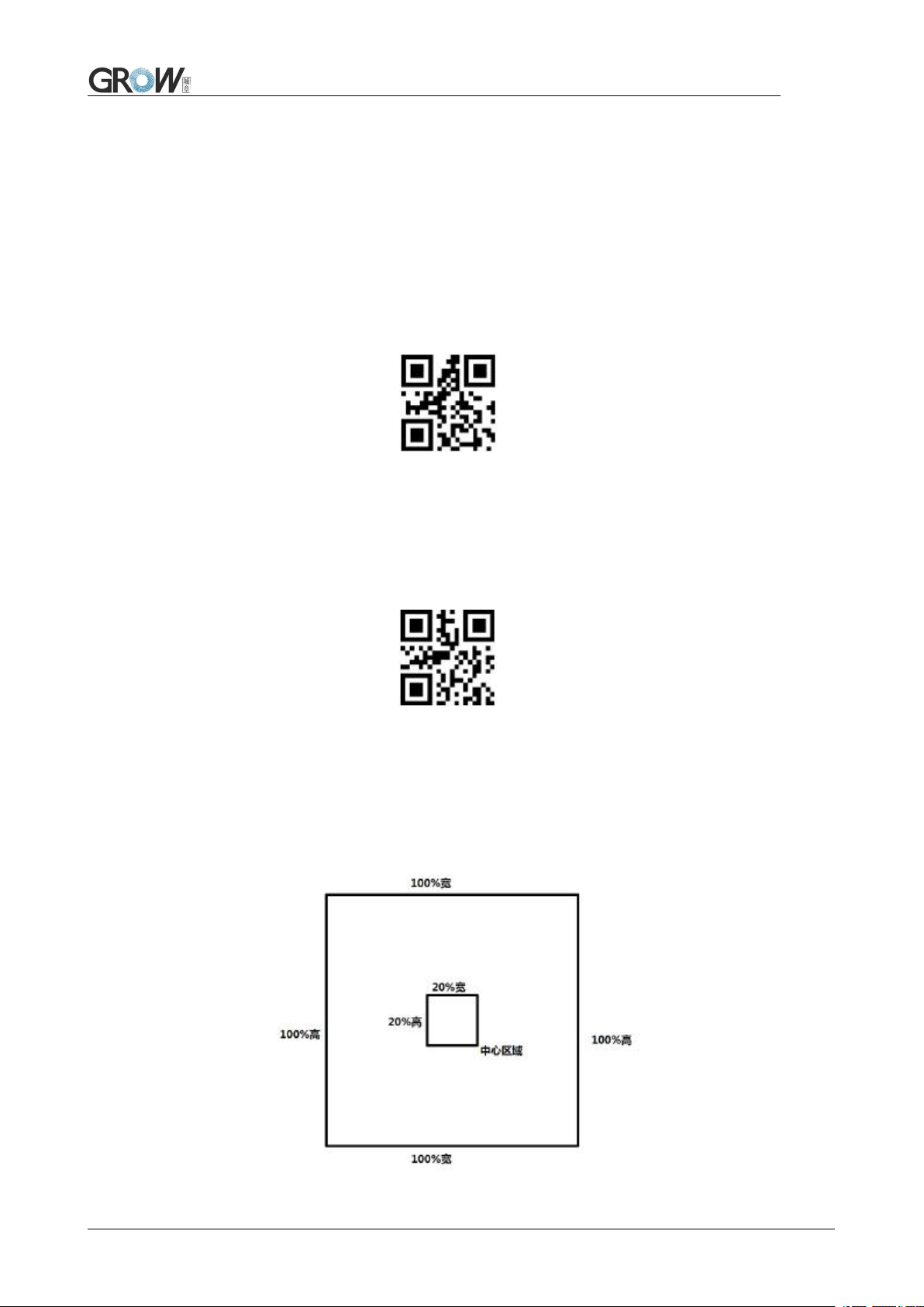
4.2 Central Area only
When the reading area is the central area, the central position of the barcode must be in the central
area set. Bar codes are not within the scope of the region are not identified and output.
Central Area only
Set the size of the central area:
The central area is an area with the center of the whole image as the central point. The size of this
area is set in proportion to the width or height of the whole image, and the value range is 1-100.If set to
20, it is located in an area 20% of the width * 20% of the height of the center.
15

Modify the central area size
The common central area size can be set by scanning the following code:
central area size
-20%
central area size
-40% central area size-60%
When the common central area size does not meet the needs, users can also scan the "modify the
central area size" setting code to customize the configuration.
modify the central area size
Example: change the center area size to 50%
1. Check the character table to get the hexadecimal value of "50" characters: "32"
2. Confirm whether the setting code is on or not. If it is off, please scan the "open setting code"
setting code (see section 1.4).
3. Scan the setting code of "modify the size of central area"
4. Scan data setting codes "3" and "2" successively (see appendix D)
5. Scan "save" setting code (see appendix E)
16
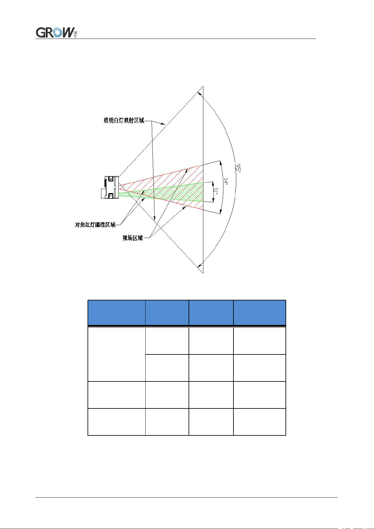
5 Lighting and Collimate
5.1 Lighting
Head lamp is used to additional lighting when read.
Normal(default): Head lamp will be on when read, others off.
Normally on: always on after boot.
OFF: head lamp is always off
*Normal Normally on Off
5.2 Collimation
There will be a pointing light beam which can help user to find best distance.
Normal(default): pointing light beam shows when read
Normally on: pointing light beam shows after power on until power off
No Collimation: no pointing light beam
Normal(default) Normally on No Collimation
17
6 Prompts
6.1 Prompts Tone
Read "buzzer drive frequency", the buzzer can be set to active/passive buzzer, the drive frequency
of the passive buzzer can also be set.
Buzzer drive frequency-passive low frequency *Buzzer drive frequency-passive medium
frequency
Buzzer drive frequency-passive high frequency Buzzer drive frequency - active drive
In the active buzzer mode, scan "Buzzer working level - high" can be set to low level when free, high
level when busy; scan "Buzzer working level - low" can be set to high level when free, low level when
busy.
*Buzzer working level - high Buzzer working level - low
Silence:Close all prompt tones
Silence on Silence off
18
6.2 Read code successfully tone
Default on Close read code successfully tone
Duration time setting. Default: 60ms
30ms 60ms
90ms 120ms
6.3 Decoding Prompt
Output Decoding Prompt: F- read unsuccessfully; S- successful
Default no decoding prompt output Output
6.4 Data Code Format
Read following to enable the reading module to read the Chinese barcode of various encoding
format.
Input Data code format GBK Input Data code format UTF8
19
 Loading...