


WiFi Module BL3353-P Product
Manual v1.1
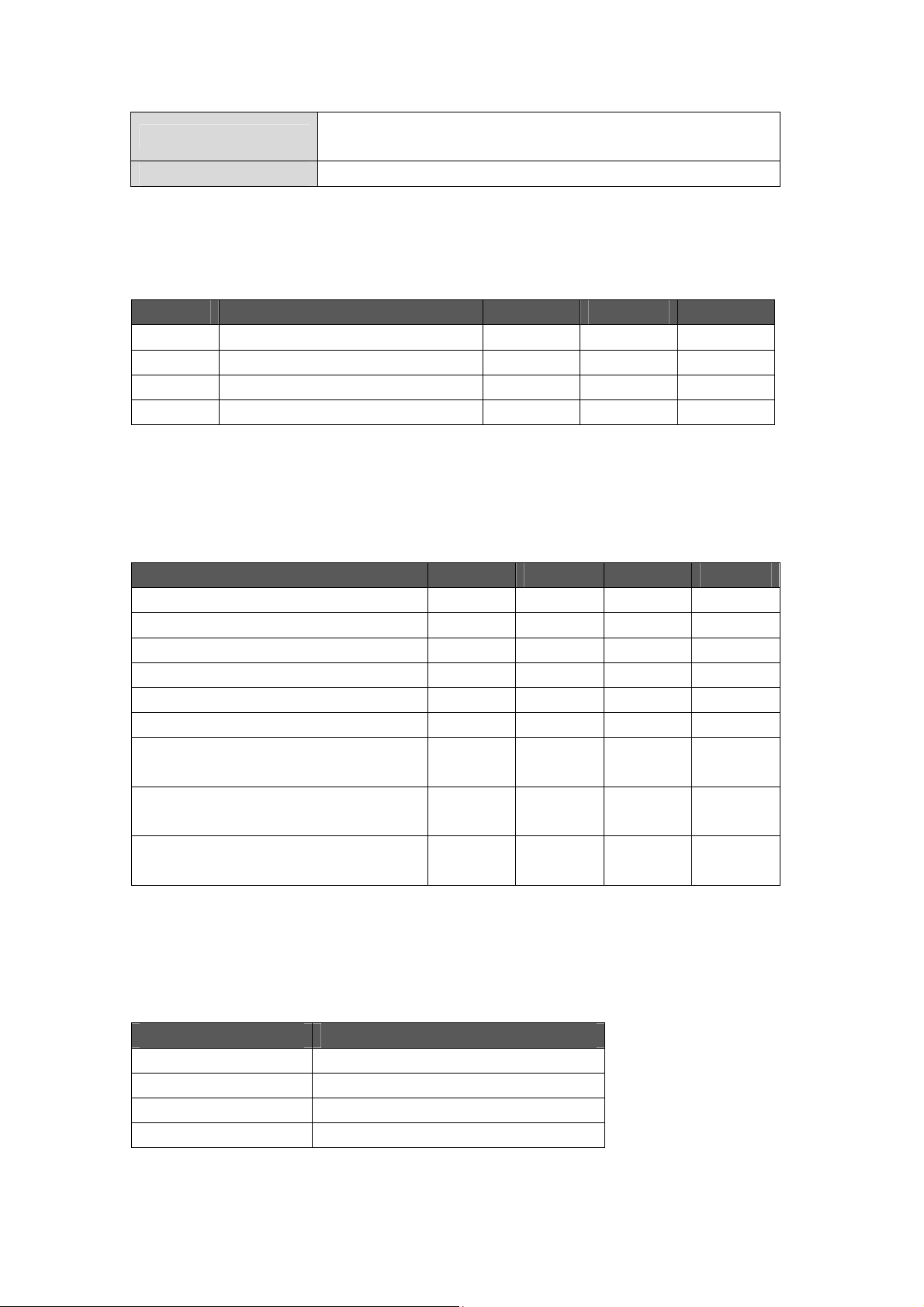
Version Date Note
1.0 Jul 15, 2018 Preliminary version
1.1 Apr 19, 2019 Added some data

Features
a. Support IEEE802.11 b/g/n standards
b. Support WEP, WPA and WPA2 encryption
c. Support UART/PWM/ADC/GPIO/I2C interfaces
d. Support STA/AP/AP+STA modes
e. Support SmartConfig
f. Support TLS/SSL/mDNS protocols
g. Support PCB antenna
h. 3.3V power supply
i. Dimensions (17.7±0.2) mm * (30±0.2) mm * (3.6±0.2) mm (with shielding case)
1. Overview
BL3353-P is an embedded Wi-Fi module designed by BroadLink, which supports
802.11 b/g/n standards and UART communication with other devices. The module
integrates radio transceiver, MAC, baseband, all Wi-Fi protocols, configurations and
network stack. It can be widely used in applications like smart home devices, remote
monitoring devices and medical care instruments.
The module integrates an ARM Cortex-M4 processor speed up to 125MHz and 256KB
SRAM with external 1MB flash.
1.1 Basic Specification
1.1.1 WLAN Parameter
Radio range
Wireless standards
Radio output
Antenna type PCB antenna
Receiving sensitivity
Stack
Data rate (max)
2.412 GHz - 2.462 GHz
IEEE 802.11 b/g/n
802.11b :16.5dBm ± 1.5dBm
802.11g :14dBm ± 1.5dBm
802.11n:13.5dBm±1.5dBm
802.11b<-83dBm@11Mbps
802.11g<-72dBm@54Mbps
802.11n<-71dBm@MCS7
IPv4, TCP/UDP/FTP/HTTP/HTTPS/TLS/mDNS
11M@802.11b, 54M@802.11g, MCS7@802.11n
Security
Network types
Encryption standard: Open/WEP-Open/WPA/WPA2
Encryption algorithm: WEP64/WEP128/TKIP/AES
STA/AP/STA+AP/WIFI Direct
1.1.2 Absolute Maximum Ratings
Symbol Description Min. Max. Units
Ts Storage temperature -40 125 °C
TA Ambient operating temperature -10 80 °C
Vdd Supply voltage 3.0 3.6 V
Vio Voltage on IO pin 0 3.3 V
1.1.3 DC Voltage and Current
Specifications Min. Typ. Max. Units
VDD 3 3.3 3.6 V
VIL (input low voltage) 0 0.8 V
VIH (input high voltage) 2 3.6 V
VOL (output low voltage) 0 0.4 V
VOH (output high voltage) 2.4 3.6 V
RX 135 mA
pulse current @TX
11b @17dBm 11Mbps
pulse current @TX
11g @14dBm 54Mbps
pulse current @TX
11n @14dBm 65Mbps
335 mA
335 mA
340 mA
1.1.4 IEEE802.11b mode
ITEM Specification
Modulation Type DSSS / CCK
Frequency range 2412MHz~2462MHz
Channel CH1 to CH11
Data rate 1, 2, 5.5, 11Mbps
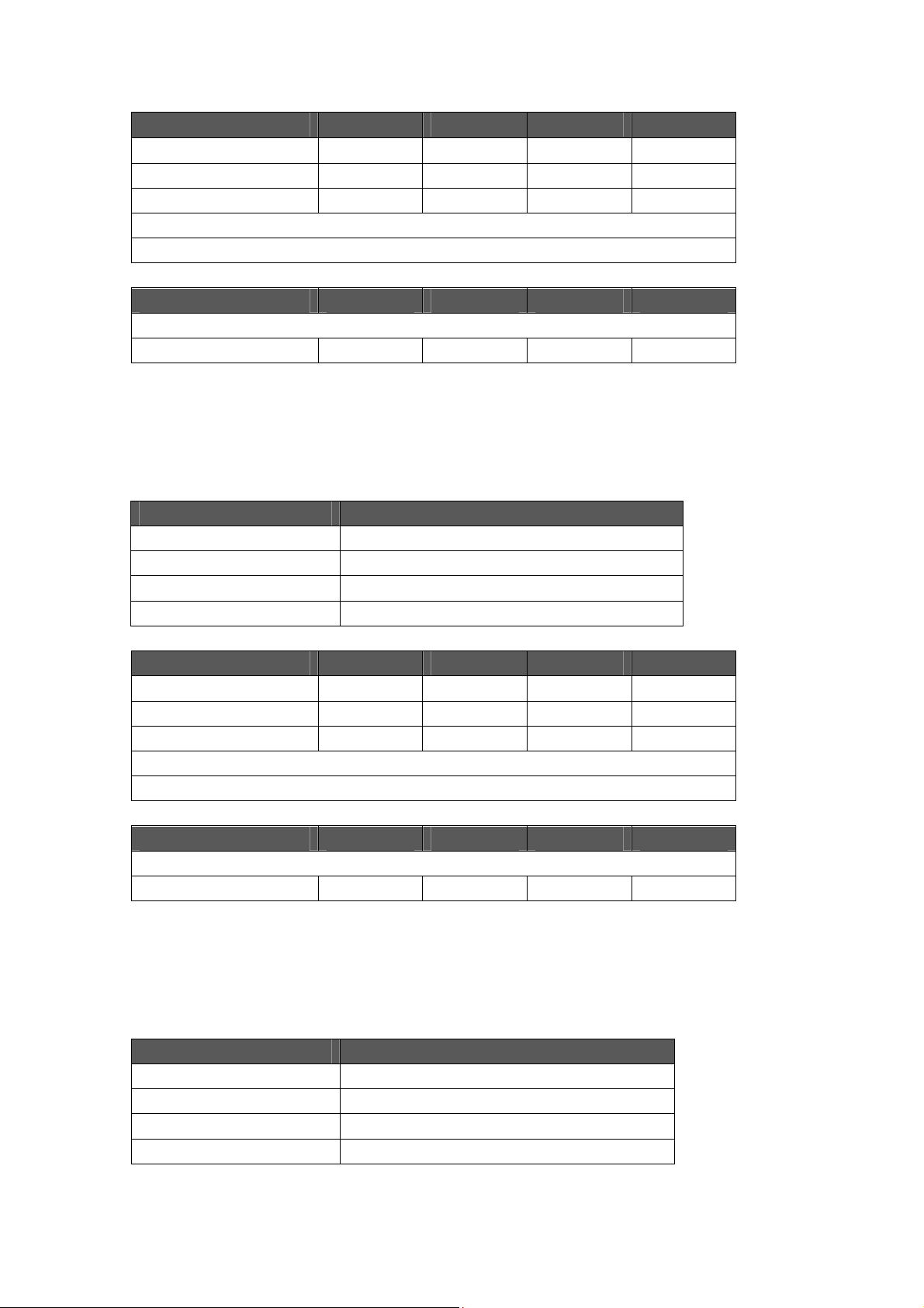
TX Characteristics Min. Typical Max. Unit
Power@11Mbps 16.5 dBm
Frequency Error -10 +10 ppm
EVM@11Mbps -20 dB
Transmit spectrum mask
Pass
RX Characteristics Min. Typical Max. Unit
Minimum Input Level Sensitivity
11Mbps (FER≦8%)
-86 dBm
1.1.5 IEEE802.11g mode
ITEM Specification
Modulation Type OFDM
Frequency range 2412MHz~2462MHz
Channel CH1 to CH11
Data rate 6, 9, 12, 18, 24, 36, 48, 54Mbps
TX Characteristics Min. Typical Max. Unit
Power@54Mbps 14 dBm
Frequency Error -10 +10 ppm
EVM@54Mbps -30 dB
Transmit spectrum mask
Pass
RX Characteristics Min. Typical Max. Unit
Minimum Input Level Sensitivity
54Mbps -74 dBm
1.1.6 IEEE802.11n 20MHz bandwidth mode
ITEM Specification
Modulation Type OFDM
Frequency range 2412MHz~2462MHz
Channel CH1 to CH11
Data rate MCS0/1/2/3/4/5/6/7
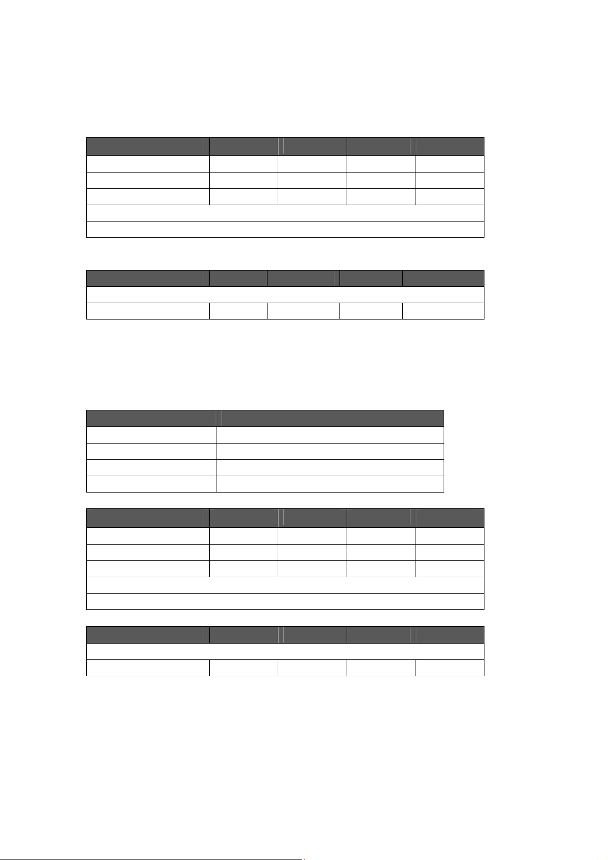
TX Characteristics Min. Typical Max. Unit
Power@HT20, MCS7 13.5 dBm
Frequency Error -10 +10 ppm
EVM@HT20, MCS7 -30 dB
Transmit spectrum mask
Pass
RX Characteristics Min. Typical Max. Unit
Minimum Input Level Sensitivity
MCS7 -71 dBm
1.1.7 IEEE802.11n 40MHz bandwidth mode
ITEM Specification
Modulation Type OFDM
Frequency range 2412MHz~2452MHz
Channel CH1 to CH9
Data rate MCS0/1/2/3/4/5/6/7
TX Characteristics Min. Typical Max. Unit
Power@HT40, MCS7 13 dBm
Frequency Error -10 +10 ppm
EVM@HT40, MCS7 -30 dB
Transmit spectrum mask
Pass
RX Characteristics Min. Typical Max. Unit
Minimum Input Level Sensitivity
MCS7 -66 dBm

1.
2
d
i
n
t
N
D
R
X
P
P
e
o
X
a
P
E
E
Har
ware
1.2.1
1.2.2
Mechan
Pin Defi
cal Dim
itions
nsions
Pin In
1 G
2 V
3 N
4
erface
D
D
ST
0
T
S
I_MOSI
G
IOA23
Descripti
GND
3.3V
HW reset
UART0 T
SPI interf
Support
n
ce
WM0
Type
POW
POW
I
O
I/O
R
R

Note:
RX0 UART0 RX I
SPI_CLK SPI interface
5
GPIOA18 I/O
TX2 UART2 TX O
GPIOA30 Support PWM3 I/O
6
I2C0_SDA I2C interface
RX2 UART2 RX I
GPIO29 Support PWM4 I/O
7
I2C_SCL I2C interface
I2C0_SDA I2C interface
GPIO19 I/O
8
SPI_CS SPI interface
I2C0_SCL I2C interface
GPIOA22 I/O
9
SPI_MISO SPI interface
10 GPIOA5 Support PWM4 I/O
GPIOA14 Support PWM0 I/O
11
SWD_CLK I
GPIOA15 Support PWM1 I/O
12
SWD_DATA
13 VDD 3.3V POWER
14 GND GND POWER
1. In default, UART0 is used for bypass communication and UART2 is used for
output of debugging information. Please refer to the description in DC
Characteristics for UART output current level.
2. RESET is hardware reset pin and will be effective with VIL. Configuration
information will be remained after module reset. The module is already
designed with RC reset upon power-on.
3. TX and RX in UART0 are used for communication with external MCU
powered by 3V. Please refer to the description in 3.3. DC Characteristics for
UART output current level.

1.
2
o
B
p
c
t
m
t
e
a
n
s
n
e
W
o
a
n
e
i
t
u
o
c
,
,
n
a
e
r
m
e
n
C
a
b
a
d
b
g
r
g
.3 PCB
The
gain of PC
bel
w.
Antenn
antenna o
this modu
le is approx
mate 1.2dB
as shown i
the figure
Simulate
The
following
Do not pla
and it’s be
It is reco
module an
area.
Do not us
Keep the a
PCB to ens
recautions
e any elect
ter to leave
mended to
enna and
the modul
ntenna of
ure better p
hould be c
rical compo
this area bl
not place
ot design a
inside any
i-Fi modul
erformance
d radiation pat
nsidered d
nents or gr
nk on PCB.
any electri
y circuit or
metal case
next to th
of antenna
ern of antenna
ring desig
unding in
al compon
bond copp
r containe
e edge of
as illustrat
gain
ing with P
ntenna are
nts within
r on main
s with met
ain board
d below.
B antenna:
on main
30mm ran
oard unde
l painting.
uring desi
oard
e of
this
n of

1.
3
d
o
i
o
e
h
p
s
w
D
e
n
b
o
d
D
o
u
a
o
c
t
T
t
h
o
c
o
u
Ref
rence
esign
For
devices wit
mo
ule UART
If y
ur device i
des
gn your o
acc
rding to ac
1.3.1
UART In
3.3V pow
ort accordi
powered
n circuit f
tual circuit
erface
r supply, y
g to the ill
y 5V, you c
r power c
esign.
esign
u can dire
stration.
n refer to
onversion.
tly connec
he circuit s
he value
the device
own in the
f resistor
UART port
figure bel
an be adj
with
w or
sted

1.
3
4
M
2
e
o
n
e
t
0
a
7
y
o
d
d
t
e
r
l
e
u
.
u
w
C
2
t
u
d
g
w
r
o
a
0
d
e
n
n
.2 Pow
If an LDO
considered
capacitor c
It is recom
enough p
The modul
or both pi
1.
Oth
Inte
gration ins
OE
Manual v
2.
List of
r Suppl
is used t
to be use
an be consi
mended to
wer supply
e is design
s.
r
ructions fo
1
pplicab
Requir
supply th
with 10u-
ered to be
supply the
o the mod
d with 2x 3
host prod
e FCC r
ement
module
22u; If a D
used with
module wi
le and avoi
3V pins. Yo
uct manufa
les
ith 3.3V p
DC is use
2uF
h power hi
d power do
can powe
cturers acc
wer, C1 c
to supply
her than 4
n during
the modul
rding to K
pacitor ca
3.3V powe
00mA to e
ata
e with eithe
DB 996369
be
r, C1
sure
r pin
D03
FCC
Part 15.24

2.3 Specific operational use conditions
product is a Single-modular transmitter policies independent of any host. not applicable.
2.4 Limited module procedures
product is a Single-modular transmitter. it is not a limited module. not applicable.
2.5 Trace antenna designs
prodcut with a PCB antenna. not applicable.
2.6 RF exposure considerations
20 cm from a person’s body
2.7 Antennas
prodcut with a PCB antenna. not applicable.
2.8 Label and compliance information
Remind end customers to add "Contain FCC ID:2ATEV-BL3353-P"
2.9 Information on test modes and additional testing
requirements
product is a Single-modular transmitter.Test stand alone. not applicable.
2.10 Additional testing, Part 15 Subpart B disclaimer
Part 15B required for the entire device even though module is 15C certified.

FCC Warning
This device complies with Part 15 of the FCC Rules. Operation is subject to the following two
conditions:
(1) This device may not cause harmful interference, and (2) this device must accept any
interference received, including interference that may cause undesired operation.
NOTE 1: Any changes or modifications to this unit not expressly approved by the party
responsible for compliance could void the user's authority to operate the equipment.

FCC Radiation Exposure Statement:
This equipment complies with FCC radiation exposure limits set forth for an uncontrolled
environment. End users must follow the specific operating instructions for satisfying RF exposure
compliance.
Note 1: This module certified that complies with RF exposure requirement under mobile or fixed
condition, this module is to be installed only in mobile or fixed applications.
A mobile device is defined as a transmitting device designed to be used in other than fixed
locations and to generally be used in such a way that a separation distance of at least 20
centimeters is normally maintained between the transmitter's radiating structure(s) and the body of
the user or nearby persons. Transmitting devices designed to be used by consumers or workers that
can be easily re-located, such as wireless devices associated with a personal computer, are
considered to be mobile devices if they meet the 20 centimeter separation requirement.
A fixed device is defined as a device is physically secured at one location and is not able to be
easily moved to another location.
Note 2: Any modifications made to the module will void the Grant of Certificatio n, t his module is
limited to OEM installation only and must not be sold to end-users, end-user has no manual
instructions to remove or install the device, only software or operating procedure shall be placed
in the end-user operating manual of final products.
Note 3: Additional testing and certification may be necessary when multiple modules are used.
Note 4: The module may be operated only with the antenna with which it is authorized. Any
antenna that is of the same type and of equal or less directional gain a s an antenna t hat is
authorized with the intentional radiator may be marketed with, and used with, that intentional
radiator.
Note 5: To ensure compliance with all non-transmitter functions the host manufacturer is
responsible for ensuring compliance with the module(s) installed and fully operational. For
example, if a host was previously authorized as an unintentional radiator under the Supplier’s
Declaration of Conformity procedure without a transmitter certified module and a module is added,
the host manufacturer is responsible for ensuring that the after the module is installed and
operational the host continues to be compliant with the Part 15B unintentional radiator
requirements. Since this may depend on the details of how the module is integrated with the host,
Hangzhou BroadLink Technology Co., Ltd.shall provide guidance to the host manufacturer for
compliance with the Part 15B requirements.
Note 6: FCC ID label on the final system must be labeled with “Contains FCC ID:
2ATEV-BL3353-P” or “Contains transmitter module FCC ID: 2ATEV-BL3353-P”.

IC WARNING
This device contains licence-exempt transmitter(s) that comply with Innovation, Science and
Economic Development Canada’s licence-exempt RSS(s). Operation is subject to the following
two conditions:
(1) This device may not cause interference.
(2) This device must accept any interference, including interference th at may cause undesired
operation of the device.
L’émetteur/récepteur exempt de licence conten u dans le présent appareil est conforme aux CNR
d’Innovation, Sciences et Développement économique Canada applicables aux appareils radio
exempts de licence. L’exploitation est autorisée aux deux conditions suivantes:
1. L’appareil ne doit pas produire de brouillage;
2. L’appareil doit accepter tout brouillage radioélectrique subi, même si le brouillage est
susceptible d’en compromettre le fonctionnement.
IC Radiation Exposure Statement:
This device and its antenna(s) must not be co-located with any other transmitters except in
accordance with IC multi-transmitter product procedures. Referring to the multi-transmitter policy,
multiple-transmitter(s) and module(s) can be operated simultaneously without reassessment
permissive change.
Cet appareil et son antenne (s) ne doit pas être co-localisés ou fonctionnement en association avec
une autre antenne ou transmetteur.
This equipment complies with IC RSS-102 radiation exposure limits set forth for an uncontrolled
environment. This equipment should be installed and operated with minimum distance 20cm
between the radiator & your body.
Cet équipement est conforme aux limites d'exposition aux rayonnements IC établies pour un
environnement non contrôlé. Cet équipement doit être installé et utilisé avec un minimum de
20cm de distance entre la source de rayonnement et votre corps.
This module is limited to OEM installation only and must not be sold to end-users, end-user has
no manual instructions to remove or install the device, only software or operating procedure shall
be placed in the end-user operating manual of final products. Additional testing and certification
may be necessary when multiple modules are used.
Any changes or modifications not expressly approved by the manufacturer could void the user's
authority to operate this equipment.
The final end product must be labeled in a visible area with the following " Contains IC:
25062-BL3353P ".
 Loading...