

Page 1

X tra
TM
IN STRUCTION MAN UAL Ver. 1.0
TM
TM
• Ready-to-fly in less than one hour
• Comes with engine, radio,and control linkages installed.
• N o glue required for assembly (no smell,no mess)
• Pre-covered and trimmed in genuine UltraCote
• Three fun options available:Sailplane Launch,Photo O P, Drop Box
(Action figure and camera not included)
Additional items required to get the X tra Easy into the air:
• Hangar 9 Field Kit, which includes glow plugs, fuel pump,
4-way wrench, glow plug igniter with charger,
Start Stick and tote box (Part H AN START)
• Glow Fuel (10% or 15% nitro content recommended)
(H AN 3109–3115)
Specifications:
• W ingspan: .......................................................................................... 69"
• Length: ............................................................................................... 55"
• W ing Area: Standar d: .......................................................... 793 sq. in.
• W eight ( Approximat e): ...................................................... 6
• Engine Supplied: ........................................ MD S .40 2-Cycle Engine
®
1
/4–7 lbs.
Page 2

A.Assemble W ing
Tape Strip
C. Mount Main Landing Gear
2
Short Screws
Page 3
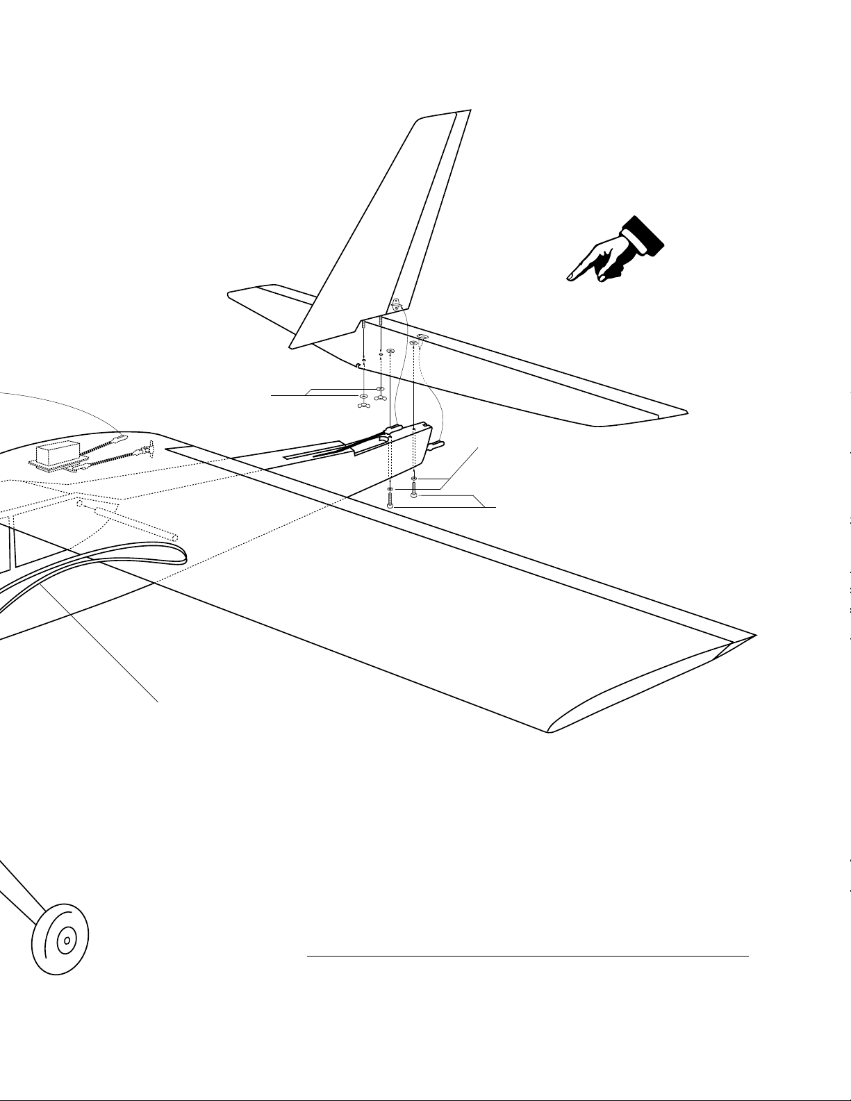
Large Washers
B. Bolt on Tail
aSmall Washers
Long Screws
Rubber Bands (5 per side) to hold wing
Assembly Diagram
For reference only. Please carefully read
the manual for detailed instructions.
3
Page 4
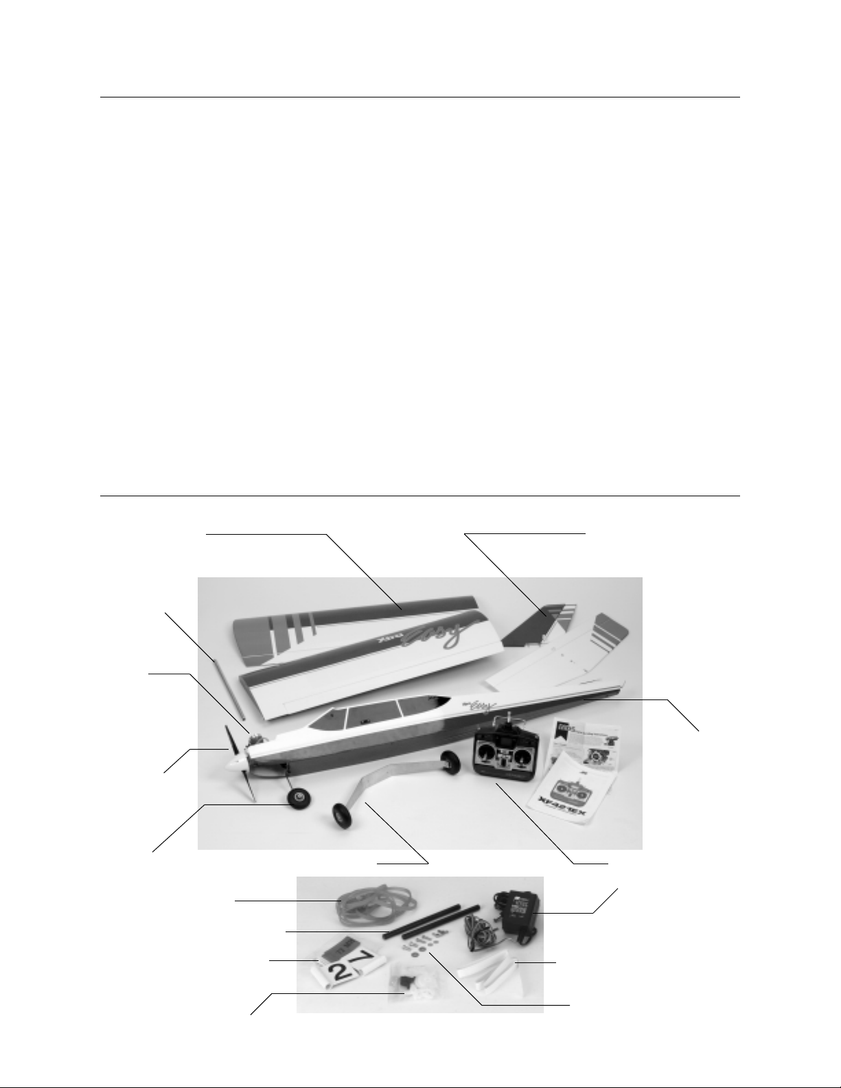
Table of Contents
Major Parts Layout . . . . . . . . . . . . . . . . . . . . . . . . . . . . . . . . . . . . . . . . . . . . . . . . . . . . . . . . . . . . . . . . . . . . . . . . . . . . . . . . . . . . . . . 4
Stap A: Assembly of the Wing . . . . . . . . . . . . . . . . . . . . . . . . . . . . . . . . . . . . . . . . . . . . . . . . . . . . . . . . . . . . . . . . . . . . . . . . . . . . . . 5
Step B: Installing the Tail Assembly . . . . . . . . . . . . . . . . . . . . . . . . . . . . . . . . . . . . . . . . . . . . . . . . . . . . . . . . . . . . . . . . . . . . . . . . . . 6
Step C: Installing the Main Landing Gear/Wing Hold Down Dowels . . . . . . . . . . . . . . . . . . . . . . . . . . . . . . . . . . . . . . . . . . . . . . . . . 7
Final Assembly . . . . . . . . . . . . . . . . . . . . . . . . . . . . . . . . . . . . . . . . . . . . . . . . . . . . . . . . . . . . . . . . . . . . . . . . . . . . . . . . . . . . . . . . . . 8
Pre-flight Checks . . . . . . . . . . . . . . . . . . . . . . . . . . . . . . . . . . . . . . . . . . . . . . . . . . . . . . . . . . . . . . . . . . . . . . . . . . . . . . . . . . . . . . . . 8
Xtra Easy Control Throw Specifications . . . . . . . . . . . . . . . . . . . . . . . . . . . . . . . . . . . . . . . . . . . . . . . . . . . . . . . . . . . . . . . . . . . . . . . 9
Pre-flight Checks at the Flying Field . . . . . . . . . . . . . . . . . . . . . . . . . . . . . . . . . . . . . . . . . . . . . . . . . . . . . . . . . . . . . . . . . . . . . . . . . 10
Flight Instructions . . . . . . . . . . . . . . . . . . . . . . . . . . . . . . . . . . . . . . . . . . . . . . . . . . . . . . . . . . . . . . . . . . . . . . . . . . . . . . . . . . . . . . . 10
Propeller Safety Instructi ons . . . . . . . . . . . . . . . . . . . . . . . . . . . . . . . . . . . . . . . . . . . . . . . . . . . . . . . . . . . . . . . . . . . . . . . . . . . . . . . 11
AMA Safety Code . . . . . . . . . . . . . . . . . . . . . . . . . . . . . . . . . . . . . . . . . . . . . . . . . . . . . . . . . . . . . . . . . . . . . . . . . . . . . . . . . . . . . . . 12
Grossary of Terms . . . . . . . . . . . . . . . . . . . . . . . . . . . . . . . . . . . . . . . . . . . . . . . . . . . . . . . . . . . . . . . . . . . . . . . . . . . . . . . . . . . . . . . 13
Fun Options . . . . . . . . . . . . . . . . . . . . . . . . . . . . . . . . . . . . . . . . . . . . . . . . . . . . . . . . . . . . . . . . . . . . . . . . . . . . . . . . . . . . . . . . . . . 14
Major Parts Layout
Wings (HAN1302)
Note: The replacement parts consist of wi ngs only;
servo/linkages not included.
Wing Tube
(HAN1303)
Engine
MDS FS Pro . 40
(M DSE04001)
w/muffler
Propeller
(M AS1060)
10" x 6"
Nose Gear
(HAN1306)
Main Landing Gear (HAN1305)
w/wheels
#64 Rubber Bands
Tail Assembly (HAN1304)
Horizontal Stabilizer w/elevator
Vertical Stabil izer w/rudder
Fuselage
(HAN1301)
Replacement does
not include motor
or radio.
Transmitter (JR 421EX)
Tx/Rx Charger
Wing Dowels
Radio Frequency Identifi ers
Servo accessories
Misc. Package
Central Wing Tape
Tail & Landing Gear Hardware
4
Page 5
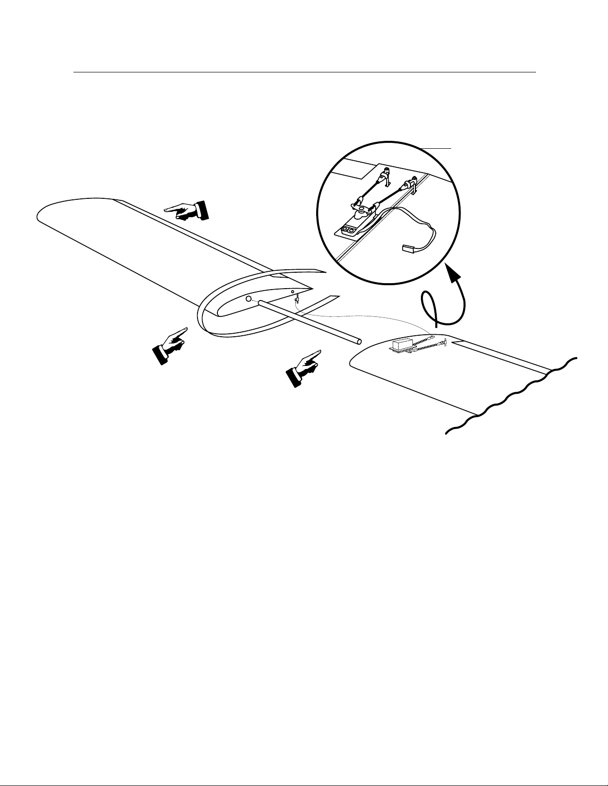
Step A: Assembly of the Wing
Remove shipping tape.
(Step A-1)
Bottom view of wing
Attach clevis.
(Step A-4)
Wrap supplied
clear tape around
the center joint.
(Step A-3)
Carefully remove the contents from the box. It’s recommended
that you charge the transmitter and receiver batteries for 16 hours,
as per the instruction included with the radio.
Step A-1
To assemble the wing, first remove the wings from their protective
plastic bag. Remove the pieces of tape holding each aileron in
place. The hinges of the ailerons have already been glued in place.
Flex the ailerons back and forth to make sure movement is free.
Step A-2
Locate the aluminum tube and carefully slide it into one of the
holes in either of the wing halves. The fit may be snug, so use a
gentle twisting motion. One wing has a short metal pin projecting
from the area near the trailing edge. This is used to key the wings
together. Slide the other wing half onto the aluminum tube until
the wing is joi ned. Be sure the metal pin fi ts i nto the hole in the
other wing half.
Slide the metal rod in one panel.
Then, attach the other panel.
(Step A-2)
Step A-3
Locate the clear tape and apply to the center joint of the wing,
around the top and bottom.
Step A-4
The aileron servo lead has been tied around the aileron li nkages
to keep them from moving during shipment. There is a tag identifying the lead as the aileron lead. Untie the lead so it is free and
the aileron li nkages are free. One of the aileron linkages has
already been attached. A small piece of tubing (cl evis keeper) is
used to hold the clevis closed. This is done to prevent accidental
opening of the clevis in fl ight.
Connect the other aileron linkage being sure the clevis is securely
snapped. Position the small piece of tubing to hold the clevis closed.
Congratulations! You have just completed assembly of the wing.
5
Page 6
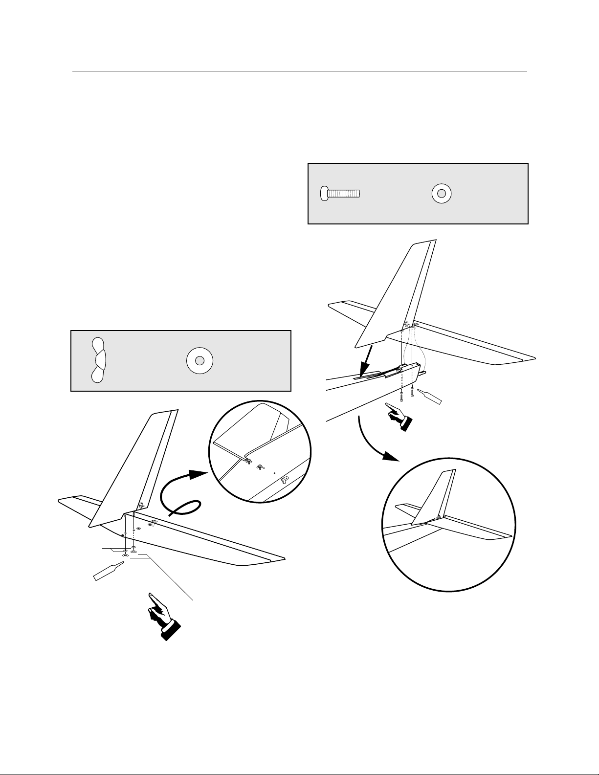
Step B: Installing the Tail Assembly
Locktite
Locktite
Locate the horizontal stabilizer and the vertical stabilizer. The
rudder and elevator are al ready attached and hi nged. The control
horns are also attached.
Remove any shipping tape that might be holding the rudder and
elevator in place. Check to make sure these control surfaces
move freely.
Step B-1
Begin by installi ng the vertical stabilizer onto the horizontal stabilizer. Insert the threaded rods in the vertical stabilizer through the
holes in the horizontal stabil izer.
Locate the two large washers and the two wi ng nuts. Use them to
secure the horizontal stabilizer to the vertical stabilizer.
Be sure to apply a small drop of Locktite (included) to the threaded rods before tightening the wing nuts.
Wing Nut
Large Washer
Step B-2
Slide the tail assembly into the groove on the rear fuselage
top. Lift the rudder pushrod so it passes on top of the
horizontal stabilizer.
Long Screw
Small Washer
Step B-2
Step B-1
Large
Washer
Apply Locktite to
the threaded rods
before installing
wing nuts.
Apply Locktite to the screws
before installing.
Slide tail assembly into slot
at fuselage rear.
Wing Nut
Attach the vertical stabilizer to the horizontal
stabilizer using washer and wing nut.
6
Page 7
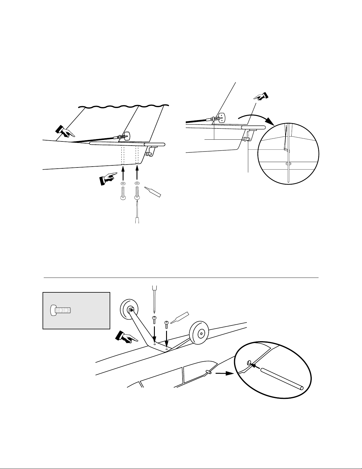
Step B-3
Loc
ktite
Locktite
Install a small washer on each of the two small screws. Appl y
Locktite (included) to the small screws. Then, place the screw on
a standard Phillips screwdriver. Hint: It is helpful to use a
good #2 magnetic screwdriver. Insert through the holes in
the bottom of fuselage and into the mounting holes into the hori zontal stabil izer. Securely tighten, then check that the stabilizer is
firmly fixed to the fuselage.
Step B-4
Connect the rudder and elevator pushrod clevises to the rudder
and elevator control horns at the outer most hole. See illustration
below.
Be sure to check to make sure the clevis keepers are over each
clevis. This prevents the clevis from coming open accidentally
during flight.
Step B-3
Note: The rudder pushrod is positioned
above
horizontal
stabilizer.
Place the screw with washer
on the Phillips screwdriver
and insert into the hole in
bottom of the fuselage.
Apply a small drop of Locktite
to screw when mounting the
tail assembly to fuselage.
Step B-4
Clevis
Keeper
Clevis attached to
outer most hole
Connect clevis to outer most
hole of control horn.
Secure the rudder
and elevator clevis.
Step C: Installing the Main Landing Gear/
Wing Hold Down Dowels
Short Screw
Step C-1
Mount landing gear to
fuselage with the two
screws provided.
Step C-1
Locate the aluminum main l anding gear. The wheels have already
been attached. You should have two screws remaining from the
hardware package. Apply a drop of Locktite to each screw. Then,
insert them through the holes in the landing gear and attach the
landing gear to the fuselage.
Apply Locktite to threads of the screws
prior mounting to landing gear.
Step C-2
Step C-2
Locate the two wing hol d- down dowels and insert one into each
of the two holes located in the fuselage, using a careful twisting
motion to install. The dowels should be positioned so an equal
amount is projecting from either side of the fuselage.
7
Page 8
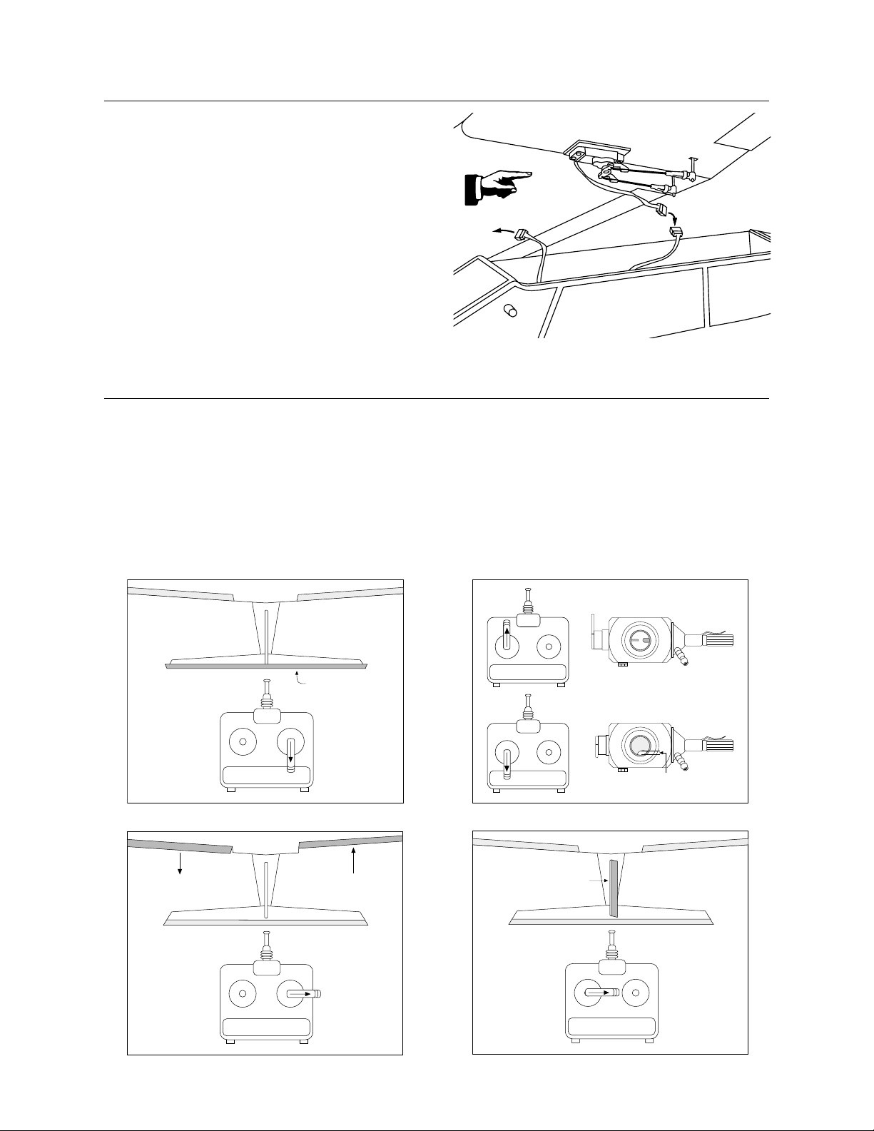
Final Assembly
ELEVATOR
ELEVATOR
Plug the aileron servo connector into the connector marked
“aileron” located in the fuselage. This will connect the aileron
servo in the wing to the aileron channel of your receiver.
Temporarily attach the wing to the fuselage by stretching a rubber
band from wing hold- down dowels starting at the leading edge of
the wing back to the trailing edge of the wing. For now, use just
two rubber bands to mount the wing in posi tion.
Pre-flight Checks
The correct servo directions are pre-adjusted, but it’s a good idea
to confirm the correct direction. After charging the transmitter and
receiver batteries per the instruction included with the radio, turn
on the transmitter and airplane and check that the controls are
moving i n the correct direction, as per the illustration below.
Moving the right stick down should cause the elevator to move
upward. M oving the right sti ck to the right should move the right
Charger
Aileron
aileron up (looking from the back of the airplane). M oving the left
stick to the right should move the rudder to the right. Now, check
the throttle. Look into the carburetor. With the throttle (left stick)
in the upper position, the carburetor should be fully open.
If any of the above controls are working in the wrong direction,
consul t the 421EX radio manual on servo reversing.
8
AILERON
AILERON
AILERON
CARBURETOR
1/16”
THROTTLE
RUDDER
RUDDER
Page 9
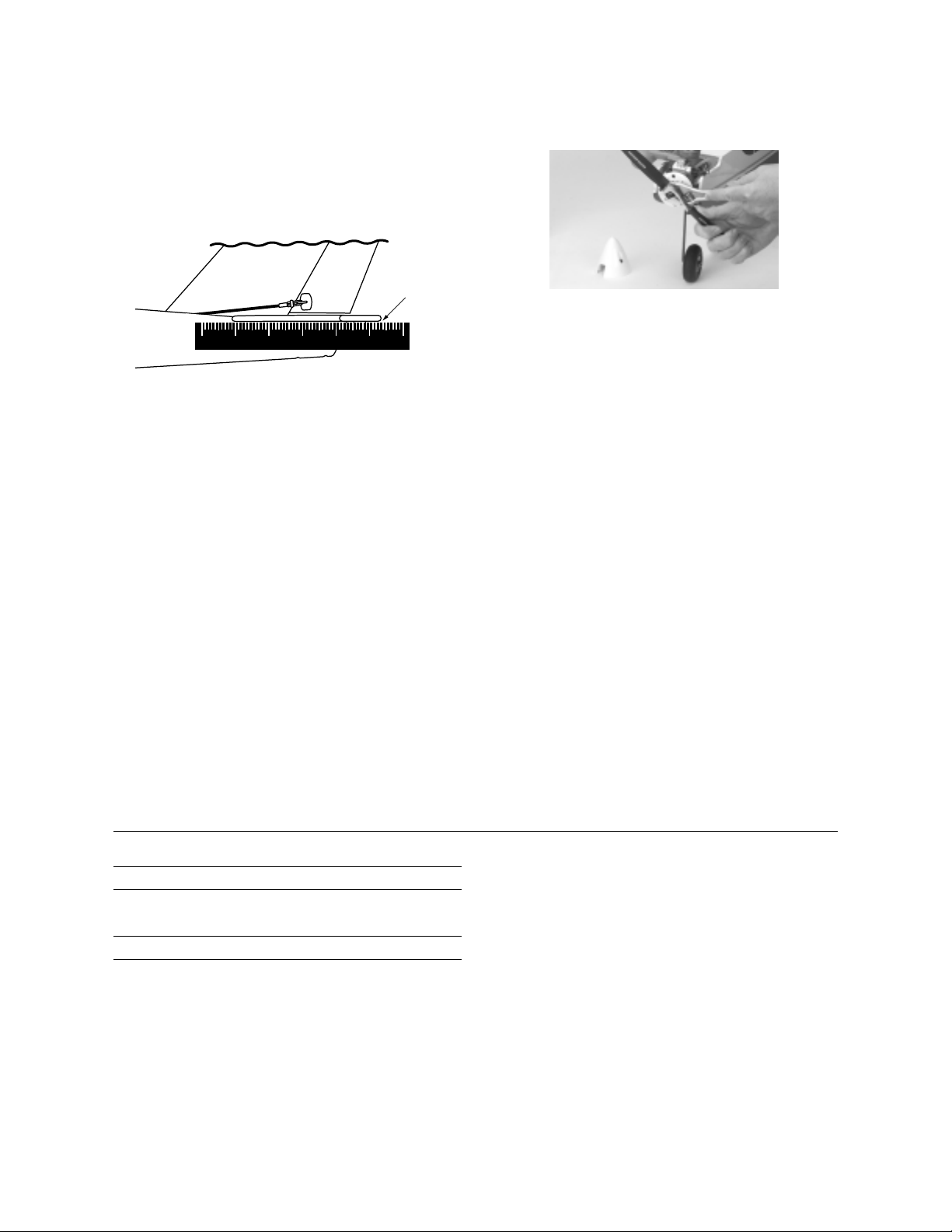
It is very important that you make sure the control surfaces (rudder, elevator and ailerons) are at 0 degrees when the transmitter
control sticks and trim switches are centered. Turn on your transmitter and receiver. Make sure the rudder, elevator and aileron
sticks are centered and the trim switches are centered. M ake sure
the throttle, aileron, rudder and elevator travel adjusts are set at
100% . Use a ruler to place against the control surfaces to see if
there are any deflections from the center (0 degrees).
0°
Adjustments to the control surfaces can be made by threading the
clevis in or out on the control rod. Threading in causes the surface to move toward the rod. Threading out causes the surface to
move away from the rod. Set the control surfaces (except throttle)
to 0 degrees.
Before each fli ght, check the screws and nuts that secure the
metal plate holding the motor in place on the metal motor mount.
Make sure the prop nut is tight by first removing the screws holding the front of the spinner. Once the spinner is removed, use
your prop wrench to make sure the prop nut is tight against the
propeller and washer on the crankshaft of the engine.
The motor high speed and low speed needle valves have been
pre-set at the factory. Refer to the motor operating instructions on
how to fine-tune the carburetor. Make any adjustments to the
high-speed needle valve in small increments (one or two “cli cks”
at a time). You should be able to easily start the engine with the
present carburetor settings. Read through the engine operating
instructions prior to starting your engine.
The Xtra Easy has been balanced at the factory. If for some reason
changes are made in battery location or a different engine is
installed, you will need to make sure the balance of the aircraft is
correct before attempting to fly it. The balance point (or center of
gravity) of the Xtra Easy is a range of 3 1/8 " to 3 5/8 " from the leading edge of the wing. If you have to add weight to the nose or tail,
use the stick-on variety sold at your local hobby shop.
Make sure the clevises are connected to the outer hole of the
control horn of the rudder and elevator control horns and that the
clevis keepers are in place.
Xtra Easy Control Throw Specifications
Elevator
Rudder
Ailerons
3
/8 " up
3
/4 " right
(Measured at the bottom of the rudder)
1
/4 " up
To achieve these throws with 100% travel adjust in the transmitter,
the linkages need to be hooked up in the foll owing manner:
• Elevator: At the control surface, use the outermost hole on the
control horn. At the servo, use the hole 8mm out from the center at the servo arm. This is the innermost hole on the “X” arm.
3
/8 " down
3
/4 " left
1
/4 " down
• Rudder/Nose wheel: At the control surface, use the outer-
most hole on the control horn. At the servo, use the 8mm hole
out from the center of the servo arm. This is the innermost hole
in the “X” arm. The nose wheel i s located 11mm out from the
center on the servo arm and at the outermost hole on the nose
wheel steering arm.
• Ailerons: At the torque rod, the nylon horn bracket needs to
be screwed on the torque rod such that it is 17mm from the surface of the wing. At the servo, use the hole 8mm out from the
center at the servo arm. This is the innermost hole on the “X”
arm. This gives the exact throw given above.
• Throttle: At the carburetor, use the innermost hole. At the
servo, a location of 12mm from center should be used.
9
Page 10

Pre-Flight Checks at the Flying Field
Important: Be sure your batteries are fully charged, per the
instructions incl uded with your radio system.
Perform a ground range check before each day’s flying. Proceed
as follows:
• Do not extend the transmitter antenna. Turn the transmitter
“ON.”
• Turn the model “ON.”
• Slowly walk away from the model while moving the control surfaces. The aircraft should function properly at a
distance of 75–100 feet.
• Make sure all trim levers on the transmitter are in the
proper position.
• Check to be sure all servo and swi tch harness plugs are
secure in the receiver.
Starting the Engine: General procedures (refer to engine oper-
ating i nstructions)
• Fill the tank with fuel.
• Open the throttle (turn ON the transmitter and receiver;
move the throttle stick to center position).
• Choke the engine (place thumb over carburetor and rotate
prop several ti mes).
• Reduce throttle to an idle position.
• Connect the glow-plug ignitor.
• Use a “Chicken Stick” or an electric starter to turn engine
over.
• To stop the engine after it starts, simply pinch the fuel line
until the engine stops due to lack of fuel.
• Refer again to the operating instructions on how to adjust
the high-speed needle valve.
Flight Instructions
For first- time pilots, the thought of flying their Xtra Easy through
loops, rolls, and perfect three-point landings can be thrilling.
Learning to fly, however, takes time, patience, and most importantly, a good i nstructor. If you’re a first- ti me pilot, don’t try to fly
the Xtra Easy alone. Seek an experienced instructor. Your local
hobby shop can put you in touch with an instructor in your area
who can fly and trim your Xtra Easy, and then give you your first
chance on the “sticks” with very little risk of damage to the airplane. We cannot overemphasize the importance of having a
qualified instructor to help you through your first flight. Don’t try
it alone!
The JR 421EX system has a built-in trainer system or “ buddy
box” option. The transmitter can be used with any JR transmitter
and a trainer cord (JRPA130). Use of the “buddy box” for the first
few flights is highly recommended.
10
Experienced pilots will find the Xtra Easy to be a confidence
inspiring airplane. Super stable and slow flight characteristics
make pinpoint landings a breeze. At full throttl e, the Xtra Easy is
more than capable of most sport aerobatic maneuvers. The selfrighting stabili ty of the Xtra Easy helps to make it one of the easiest airplanes you’ll ever fly.
Repair Information
In the misfortune of a crash or broken part, see your l ocal hobby
dealer for replacement parts.
Page 11

Propeller Safety Instructions
IMPORTANT!
1. Before using, remove any flash along the edges of the propeller by scraping it with a sharp knife.
2. Only use a “Chicken Stick” or electric starter to start the
engine, then make adjustments to the carburetor from behind
the engine.
3. Keep spectators at least 20 feet away and out of the path of a
rotating propeller.
WARNING
A rotating propeller can cause serious personal injury.
Follow these instructions carefully!
4. Wear safety glasses and hand protection when operating
model engines. Do not permit any objects to touch a turning
propeller. Remain clear of the propeller arc.
5. To stop the engine, cut off the fuel supply in accordance with
the manufacturer’s instructions. In any case, DO NOT stop the
propeller with your hand or other object.
6. Inspect the propeller after each flight. Discard any propeller
that has nicks, scratches, or any other visible defect. DO NOT
repair, alter, or in any way modify a propeller.
11
Page 12

AM A Safety Code
Official AMA National M odel Aircraft Safety Code
Effective January 1, 1999
Model flying MUST be in accordance with this Code in
order for AMA Liability Protection to Apply
General
1. I will not fly my model aircraft in sanctioned events, air
shows, or model flying demonstrations until it has been
proven airworthy by having been previously, successfully
fli ght tested.
2. I will not fly my model higher than approximately 400 feet
within 3 miles of an airport without notifying the airport operator. I will give right- of-way and avoid flying in the proximity
of ful l-scale aircraft. Where necessary, an observer shall be
utilized to supervise flying to avoid having models fly i n the
proxi mity of full- scale aircraft.
3. Where established, I will abide by the safety rules for the flying site I use, and I wil l not wi llfully and deliberately fly my
models in a careless, reckless and/or dangerous manner.
4. At all flyi ng sites, a straight or curved line(s) must be established in front of which all flying takes place with the other
side for spectators. Only personnel involved with flying the
aircraft are allowed in front of the flight line. Flying over the
spectator side of the li ne is prohibited, unless beyond the
control of the pilot(s). In any case, the maximum permissible
takeoff weight of the mode is 55 pounds.
5. At air shows or model flying demonstrations, a single straight
line must be established — one side which is for flying, with
the other side for spectators. Only those persons accredited
by the contest director or other appropriate official as necessary for flight operations or as having duties or functions
relating to the conduct of the show or demonstration are to be
permitted on the flying side of the line. The only exceptions
which may be permitted to the single straight line requirements, under special circumstances involving consideration
of side conditions and model si ze, weight, speed, and power,
must be jointly approved by the AMA President and the
Executive Director.
6. Under all circumstances, if my model weights over 20 pounds,
I will fly it in accordance with paragraph 5 of this section of
the AMA Safety Code.
7. I will not fly my model unless it is i dentified with my name
and address or AM A number, on or in the model. Note: This
does not appl y to models flown indoors.
8. I will not operate models with metal- bl aded propellers or with
gaseous boosts, in which gases other than air enter their
internal combustion engine(s); nor will I operate models with
extremely hazardous fuels, such as those containing tetranitromethane or hydrazine.
9. I will not operate models with pyrotechnics (any device that
explodes, burns, or propels a projectile of any kind) including, but not limited to, rockets, explosive bombs dropped
from models, smoke bombs, all explosive gases (such as
hydrogen-filled balloons), ground mounted devices launching a projectile. The only exceptions permi tted are rockets
flown in accordance with the National Model Rocketry Safety
Code or those permanently attached (as per JATO use); also
those items authorized for Air Show Team use as defined by
AST Advisory Committee (document available from AMA HQ).
In any case, models using rocket motors as primary means of
propulsi on, are limited to a maximum weight of 3.3 pounds
and a G series motor. Note: A model aircraft is an aircraft,
with or without an engine, not able to carry a human being.
10. I will not operate any turbo jet engine (axial or centrifugal
flow) unl ess I have obtained a special waiver for such specific
operations from the AMA President and Executive Director
and I will abide by any restriction(s) imposed for such operation by them. (Note: This does not apply to ducted fan models
using piston engines or electric motors.)
11. I will not consume alcoholic beverages prior to, nor during,
participation in any model operations.
Radio Control
1. I will have completed a successful radio equipment ground
range check before the first flight of a new or repaired model.
2. I will not fly my model aircraft in the presence of spectators
until I become a qualified flier, unless assisted by an experienced helper.
3. I will perform my i nitial turn after takeoff away from the pit or
spectator areas, and I will not thereafter fly over pit or spectator areas, unless beyond by control.
4. I will operate my model using only radio control frequencies
currently allowed by the Federal Communications
Commission. (Only properly licensed Amateurs are authorized to operate equipment on Amateur Band frequencies.)
5. I will not knowingly operate an R/ C system within 3 miles of a
pre-existing model club- flying site without a frequency sharing agreement with that club.
6. I will not fly my model aircraft in any racing competition,
which allows models over 20 pounds, unless that competition event is AM A sanctioned. (Competition is defined as any
situation where a winner is determined.)
7. Every organization racing event requires that all officials,
callers, and contestants must properly wear helmets, which
are OSHA, DOT, ANSL, SNELL, NOCSAE or comparable standard while on the racecourse. In addition, all officials occupying safety cages must wear protective eyewear.
12
Page 13

Glossary of Terms
• Ailerons: Each side of this airplane has a hinged control sur-
face, called an aileron, located on the trailing edge of the wing.
Move the aileron stick on the transmitter left, the left aileron
moves up and the right aileron moves down. M oving the left
aileron up causes more drag and less lift causing the wing to
drop down. When the right aileron moves down, more lift i s
created, causing the wing to rise. This interaction causes the
airplane turn or roll to the left. Perform the opposite actions,
and the airplane will roll to the right. This is how you control
the airplane’s direction in fl ight.
• Carburetor: By adjusting the needle valve in the carburetor,
you control the engine’s lean/rich fuel mixture and determine
the airplane’s speed.
• Charger: This is the device used to charge/recharge batteries.
If NiCad batteries are provided with the radio, a charger is usually provided as well.
• Clevis: The Clevis connects the wire end of the pushrod to the
control horn of the control surface. A small clip, the clevis has
fine threads so that you can adjust the length of the pushrod.
• Clunk: Located in the fuel tank, a clunk i s weighted and
ensures that the intake li ne has a steady supply of fuel.
• Computer Radio: By using advanced programming functions
of the transmitter, you can adjust the airplane without changi ng
any mechanical structures.
• Control Horn: This arm connects the control surface to the
clevis and pushrod.
• Control Surfaces: The moveable part of the wing and tail
that causes the aircraft to roll (aileron), pitch (elevator), or
yaw (rudder).
• Dead Stick: When the airplane is i n fl ight gliding, without the
engine running, it is called “dead stick” .
• Dihedral: The degree of angle (V-shaped bend) at which the
wings intersect the plane is called dihedral. More dihedral gi ves
an airplane more aerodynamic stability. Some sailplanes and
trainer planes with large dihedral dispense with ailerons and
use only the rudder to control the roll and yaw.
• Electric Starter: This is the small motor commonly used to
start the airplane’s engine.
• Elevator: The hinged control surface functions as an elevator,
which you adjust to control the airplane’s pitch axis. Pulling the
transmitter’s control stick toward the bottom of the transmitter
adjusts the elevator upward, and the airplane begins to climb.
Push the control stick forward, and the airplane begins to dive.
• Expanded Scale Voltmeter (ESV): This device is used to
check the voltage of the battery pack.
• Flight Box: The box in which you store and transport your fly-
ing equipment is called a flight box.
• Flight Pack or Airborne Pack: These interchangeable terms
describe the radio equipment that is install ed on the airplane.
• Fuel Overflow Line (Vent): This line pressures the fuel tank
and provides an even fuel flow to the engine. It also functions
as an overflow l ine when the fuel tank is full.
• Fuel Pickup Line: This line connects the fuel tank to the car-
buretor, usuall y with a clunk on the tank end to keep the fuel
flowing while the aircraft is in flight.
• Fuselage: The main body of an airplane.
• Glow Plug Clip/Battery: A 1.2-Volt battery with a clip which
is connected to your engine’s glow plug and is used to start the
engine. You remove it once the engine is running smoothl y.
• High Wing: The term describes an airpl ane that has its wings
mounted on the top of the fuselage.
• Hinge: The hinges are the moving blades on the control sur-
face that al low you to control the airplane’s movement. All
hinges must be glued properly and securely to prevent the airplane from crashing. (This has already been done for you on the
Extra Easy.)
• Horizontal Stabilizer: The horizontal surface of the tail gives
the airplane stability while in fl ight.
• Leading Edge: The front of a flying surface.
• Main Landing Gear: The wheel and gear assembly the air-
plane uses to land. It is attached to the bottom of the fuselage.
• Muffler: This device muffles engine noise and increases the
back pressure from the engine’s exhaust stack, which can
improve the airplane’s performance at low speeds. Mufflers are
usually required by R/C Clubs.
• Needle Valve: This mechanism within the carburetor adjusts
the fuel mixture and throttle. Refer to your engine’s manufacturer
instructions for di rections on how to adjust the needle valve.
• NiCad: This abbreviation stands for Nickel Cadmium, the
chemical compound used in rechargeable batteries.
• Nitro: Short for nitromethane, a fuel additive that improves an
airplane’s high-speed performance. Check your engine’s
instructions to determine the ideal nitro content for your engine.
• Nose Gear: The part of the landing gear that is attached to the
nose of the fuselage. The nose gear is usually connected to the
rudder servo to help you steer the airplane on the ground.
• Pitch Axis: The horizontal plane on which the airplane’s nose
is raised or l owered. By adjusting the elevator, you can raise the
airplane’s nose above the pitch axis (climb) or lower it below the
pitch axis (dive).
13
Page 14

• Pushrod: The rigid mechanism that transfers movement from
the servo to the control surface.
• Receiver (Rx): The receiver unit in the airpl ane receives your
signals from the ground transmitter and passes the instructions
along to the airplane’s servos.
• Roll Axis: The horizontal plane on which the airplane’s wings
are raised or lowered. By adjusting the ailerons, you can drop a
wing tip below the roll axis and cause the airplane to bank or roll.
• Rudder: The hinged control surface on the vertical stabilizer
that controls the airplane’s yaw. Moving the rudder to the left
causes the airplane to yaw left; moving the rudder to the right
causes it to yaw right.
• Servo: The servo transforms your ground commands into
physical adjustments of the airplane while it’s in the air.
• Servo Output Arm: A removable arm or wheel that connects
the servo to the pushrod — also called servo horn.
• Spinner: Term describing the nose cone that covers the pro-
peller hub.
• Switch Harness: This switch is commonly located on the
fuselage and governs the ON/OFF mechanism for the flight pack.
• Tachometer: A device that measures the engine’s rpm (rota-
tion per mi nute) by counting li ght impulses that pass through
the spinning propeller.
• Torque Rods: Inserted into the ailerons, these rigid wire rods
run along the wing’s trailing edge, then bend downward and
connect to the pushrods.
• Trainer Airplane: Designed to fly with high stability at low
speeds, a trainer model airplane allows new users some extra
reaction ti me as they learn to control the airplane’s movements.
• Transmitter (Tx): The device used on the ground to transmit
instructions to the airplane. Three transmitter modes are used in
model airplanes. The most common is M ode II, where the left
stick controls the throttle and rudder, and the right stick controls
the elevator and ailerons.
• Vertical Stabilizer: The vertical surface of the tail gives the
airplane stability while in flight.
• Wheel Collar: The round retaining pi ece that anchors wheels
in place on the wheel axle.
• Wing: Because wings provide the primary lift force on an air-
plane, adjustments to the wings affect the airplane’s movements
while in flight.
• Yaw Axis: The vertical plane through which the airplane’s nose
passes as it yaws to the left or to the right. The rudder controls
the yaw axis.
• Z-Bend: The wire ends of pushrods have Z-shaped bends,
which attach to the servo.
• Thread Locker: A liquid that solidifies; used to prevent
screws from loosening due to vi bration.
Fun Options
Hangar 9’s “Fun Options” bolt directly on the Xtra Easy. The Xtra
Easy comes with “pre-installed” blind nuts that allow you to easily bolt on the Drop Box and Photo OP.
Sailplane Launch
Now you can take a friend’s 2-meter (or smaller) sailplane, such
as Hangar 9’s Aspire, up to amazing altitudes in no time. Great
team act that makes sailplane flying fun at powered fields.
HAN1325
(Available separately)
Drop Box
With a youngster’s parachute-equipped action figure placed in the
drop box, the game is to see if you can judge the wind dri ft accurately enough to catch the figure — before it hits the ground! Or,
drop paintballs, candy, ping pong balls, streamers —
whatever’s fun and safe.
HAN1326
Photo OP
With an inexpensive camera like the Kodak®MAX or FujiFilm
Quick Snap™, you can take aerial pictures of your flying site —
you won’t believe what things look like from a bird’s-eye view!
HAN 1327
®
14
Page 15

Page 16

© Copyright 2000, Horizon Hobby, Inc. 877-504- 0233
www.horizonhobby.com
 Loading...