

Hangar 9 Twist Plug-N-Play Assembly Manual

Twist
™
Plug-N-Play
ASSEMBLY MANUAL
™
Specifications
Wingspan: ............... 47.75 in (1212.85mm)
Length: .................... 48. 38 in (1228.73mm)
Wing Area: .............. 747.37 sq in (48.2 sq dm)
Weight: ................... 5.0–6.0 lb (2.27 kg–2.72 kg)
Radio: ..................... 4-channel w/5 servos
Engine: .................... Evolution™ .46 NT

Table of Contents
Covering Colors . . . . . . . . . . . . . . . . . . . . . . . . . . . . . . . . . . . . . . . . . . . . . . . . . . . . . . . . . . . . . . . . . . .2
Additional Required Tools and Adhesives. . . . . . . . . . . . . . . . . . . . . . . . . . . . . . . . . . . . . . . . . . . . . . . .2
Contents of Kit . . . . . . . . . . . . . . . . . . . . . . . . . . . . . . . . . . . . . . . . . . . . . . . . . . . . . . . . . . . . . . . . . . . .3
Field Equipment Required. . . . . . . . . . . . . . . . . . . . . . . . . . . . . . . . . . . . . . . . . . . . . . . . . . . . . . . . . . . .3
Optional Field Equipment . . . . . . . . . . . . . . . . . . . . . . . . . . . . . . . . . . . . . . . . . . . . . . . . . . . . . . . . . . . .
Warning . . . . . . . . . . . . . . . . . . . . . . . . . . . . . . . . . . . . . . . . . . . . . . . . . . . . . . . . . . . . . . . . . . . . . . . . .3
Before Starting Assembly . . . . . . . . . . . . . . . . . . . . . . . . . . . . . . . . . . . . . . . . . . . . . . . . . . . . . . . . . . . .
Using the Manual . . . . . . . . . . . . . . . . . . . . . . . . . . . . . . . . . . . . . . . . . . . . . . . . . . . . . . . . . . . . . . . . . .4
Warranty Information . . . . . . . . . . . . . . . . . . . . . . . . . . . . . . . . . . . . . . . . . . . . . . . . . . . . . . . . . . . . . . .4
Section 1: Installing the Tail Section. . . . . . . . . . . . . . . . . . . . . . . . . . . . . . . . . . . . . . . . . . . . . . . . . . . .5
Section 2: Landing Gear Installation
Section 3: Propeller and Spinner . . . . . . . . . . . . . . . . . . . . . . . . . . . . . . . . . . . . . . . . . . . . . . . . . . . . . .7
Section 4: Radio Installation . . . . . . . . . . . . . . . . . . . . . . . . . . . . . . . . . . . . . . . . . . . . . . . . . . . . . . . . . .8
Section 5: Linkage Installation . . . . . . . . . . . . . . . . . . . . . . . . . . . . . . . . . . . . . . . . . . . . . . . . . . . . . . . .
Section 6: Attaching the Wing to the Fuselage . . . . . . . . . . . . . . . . . . . . . . . . . . . . . . . . . . . . . . . . . . .10
Adjusting the Engine. . . . . . . . . . . . . . . . . . . . . . . . . . . . . . . . . . . . . . . . . . . . . . . . . . . . . . . . . . . . . . .10
Control Throws
Recommended CG . . . . . . . . . . . . . . . . . . . . . . . . . . . . . . . . . . . . . . . . . . . . . . . . . . . . . . . . . . . . . . . .11
Preflight . . . . . . . . . . . . . . . . . . . . . . . . . . . . . . . . . . . . . . . . . . . . . . . . . . . . . . . . . . . . . . . . . . . . . . . .12
Range Testing the Radio . . . . . . . . . . . . . . . . . . . . . . . . . . . . . . . . . . . . . . . . . . . . . . . . . . . . . . . . . . . .
Notes . . . . . . . . . . . . . . . . . . . . . . . . . . . . . . . . . . . . . . . . . . . . . . . . . . . . . . . . . . . . . . . . . . . . . . . . . .13
. . . . . . . . . . . . . . . . . . . . . . . . . . . . . . . . . . . . . . . . . . . . . . . . . . . . . . . . . . . . . . . . . . .11
. . . . . . . . . . . . . . . . . . . . . . . . . . . . . . . . . . . . . . . . . . . . . . . . . . . .6
12
3
4
9
2005 Official AMA National Model Aircraft Safety Code . . . . . . . . . . . . . . . . . . . . . . . . . . . . . . . . . . . .14
Covering Colors
• White HANU870
• Pearl Purple HANU847
• Pearl Green HANU844
• Transparent Violet HANU955
Additional Required Tools and Adhesives
• Flat blade screwdriver
• Phillips screwdriver (small)
• Pliers
• Ruler
• Threadlock
2
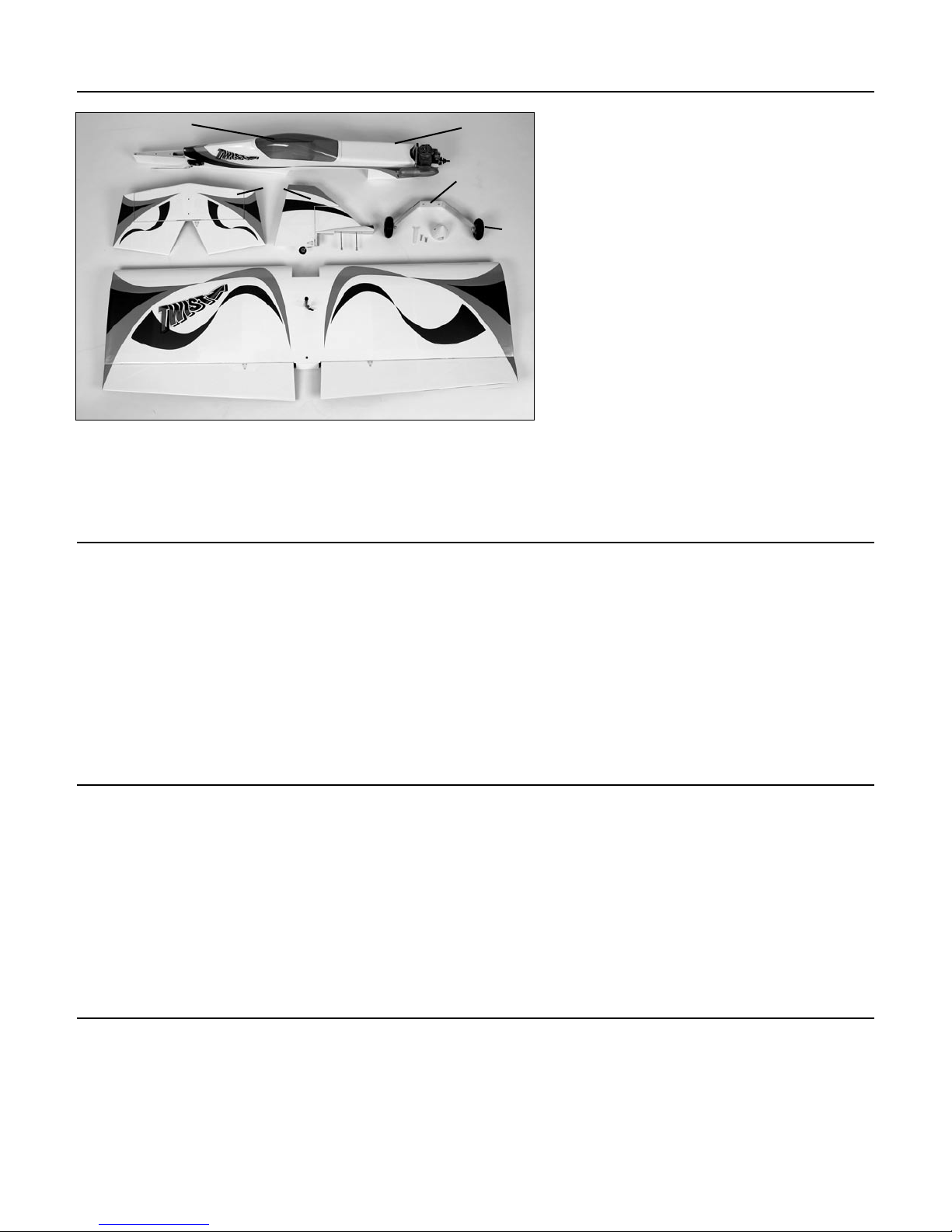
Contents of Kit
E
C
A
Field Equipment Required
B
D
Replacement Parts
A. Wing w/Aileron HAN2877
B. Fuselage HAN2876
C. Tail Set HAN2878
F
D. Landing Gear HAN2654
E. Canopy HAN2879
F. 2
Items Not Shown
Fuel Tank HAN2479
Engine Mount HAN40M
Decal Set HAN2880
3
/4" Wheels HAN305
• Propeller (APC 11x6)
• Fuel (10%–15% nitro content)
• Glow Plug Wrench (HAN2510)
• Glow Plug Igniter with Charger (HAN7101)
Optional Field Equipment
• 4-Way Wrench (DUB701)
• Fieldmate (HAN117)
• Cleaner & towels
• Extra Glow Plugs (HAN3001/3006)
Warning
• Glow Plug (HAN3001/3006)
• Manual Fuel Pump (HAN118)
• Start-Up Field Pack (HANSTART)
• Blue Block After Run Oil (EVOX1000)
• Power Panel (HAN106)
• 12V 7Ah Sealed Battery (HAN102)
• PowerPro 12V Starter (HAN161)
An RC aircraft is not a toy! If misused, it can cause serious bodily harm and damage to property. Fly only in open areas,
preferably at AMA (Academy of Model Aeronautics) approved flying sites, following all instructions included with your
radio and engine.
3
Before Starting Assembly
Before beginning the assembly of your Twist™ Plug-N-Play™, remove each part from its bag for inspection. Closely
inspect the fuselage, wing panels, rudder and stabilizer for damage. If you find any damaged or missing parts,
contact the place of purchase.
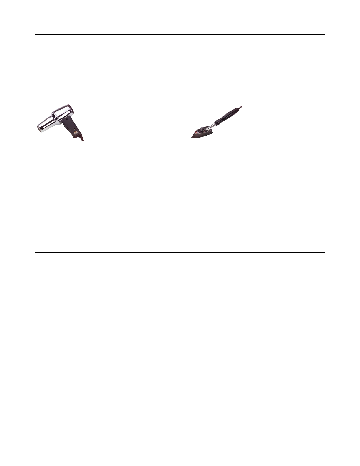
If you find any wrinkles in the covering, use a heat gun or covering iron to remove them. Use caution while working
around areas where the colors overlap to prevent separating the colors.
HAN100 – Heat Gun
HAN150 – Covering Glove
HAN101 – Covering Iron
HAN141 – Sealing Iron
Sock
Using the Manual
This manual is divided into sections to help make assembly easier to understand, and to provide breaks between
each major section. Remember to take your time and follow the directions.
Warranty Information
Horizon Hobby, Inc. guarantees this kit to be free from defects in both material and workmanship at the date of
purchase. This warranty does not cover any parts damaged by use or modification. In no case shall Horizon Hobby’s
liability exceed the original cost of the purchased kit. Further, Horizon Hobby reserves the right to change or modify
this warranty without notice.
In that Horizon Hobby has no control over the final assembly or material used for the final assembly, no liability
shall be assumed nor accepted for any damage of the final user-assembled product. By the act of using the product,
the user accepts all resulting liability.
Once assembly of the model has been started, you must contact Horizon Hobby, Inc. directly regarding any warranty
question that you have. Please do not contact your local hobby shop regarding warranty issues, even if that is where
you purchased it. This will enable Horizon to better answer your questions and provide service in the event that you
may need any assistance.
If the buyer is not prepared to accept the liability associated with the use of this product, the buyer is advised to
return this kit immediately in new and unused condition to the place of purchase.
4 4
Horizon Hobby Service Department
4105 Fieldstone Road
Champaign, Illinois 61822
(217) 355-9511
horizonhobby.com
Section 1: Installing the Tail Section
Required Parts
• Stabilizer assembly • Fuselage
• Rudder assembly
Required Tools and Adhesives
• Crescent wrench • Threadlock
• 4-40 lock nut (2) • #4 washer (2)
Step 1
Loosen the nuts on the bottom of the fuselage that are
holding the rudder/fin assembly onto the fuselage. Pull
the rudder/fin assembly straight up to remove from the
fuselage. Use care not to damage the lower portion of the
fin or the fuselage fairing.
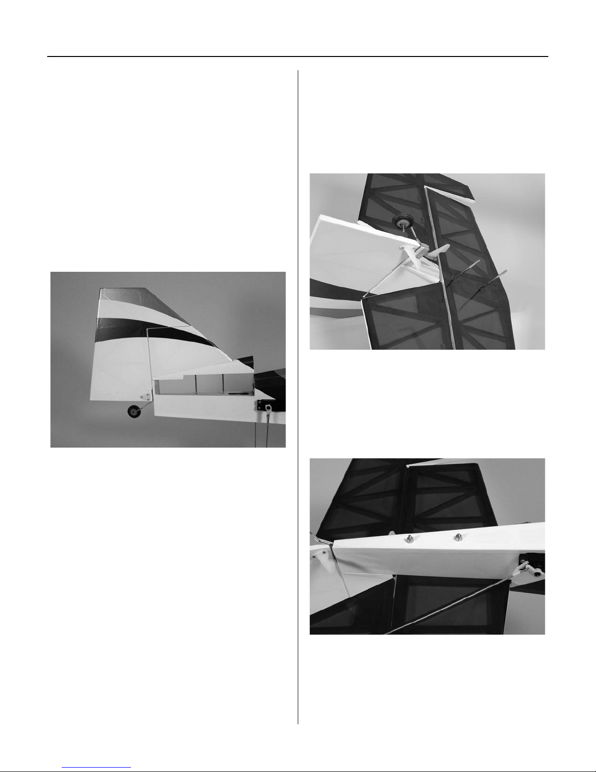
Step 2
Locate the stabilizer/elevator assembly. Position the
stabilizer/elevator assembly so the control horn will face
down, away from the fin. The threaded rods from the
rudder/fin assembly will slide into the two holes in the
stabilizer. The fuselage fairing has been slid into position
on the fin in the photograph.
Step 3
Slide the rudder/stabilizer assembly onto the fuselage.
Slide the #4 washers onto the threaded rods. Apply a drop
or two of threadlock to the exposed threads of the threaded
rods. Thread the nuts onto the rod, tightening them snugly
against the bottom of the fuselage.
5
 Loading...