

Hangar 9 toledo special 40 Assembly Manual

Specications
Wingspan: ........................................................69.5 in (1765.3mm)
Length: ...........................................................50.8 in (1290.75mm)
Wing Area: ...............................................702.8 sq in (45.3 sq dm)
Weight: .................................................. 5.5–6.25 lb (2.49–2.83 kg)
Radio: .......................................................4-channel w/4–5 servos
Engine: ..................... .40–52 2-stroke; .56–82 4-stroke; Power 46
Toledo Special 40
Assembly Manual
2 Hangar 9 Toledo Special Assembly Manual
Table of Contents
Contents of Kit and Parts Layout ......................................2
Included Hardware ............................................................3
Using the Manual ..............................................................3
UltraCote Covering Colors ................................................3
Before Starting Assembly .................................................3
Radio Systems Requirements ...........................................4
Recommended Setup–2-Stroke Glow ...............................4
Recommended Setup–4-Stroke Glow ...............................4
Recommended Setup–Electric Power (EP) .......................4
Field Equipment Required .................................................4
Optional Field Equipment ..................................................4
Additional Required Tools .................................................4
Additional Required Adhesives .........................................4
FS One ..............................................................................4
Important Information Regarding
Warranty Information ..................................................4
Landing Gear Installation ..................................................5
Tail Installation ..................................................................7
Radio Installation ..............................................................8
Linkage Installation .........................................................10
2-Stroke Engine Installation ............................................12
4-Stroke Engine Installation ............................................15
Fuel Tank Installation ......................................................18
Electric Motor Installation ...............................................20
Cowling Installation ........................................................23
Window Installation ........................................................25
Aileron Servo Installation ................................................26
Wing Installation .............................................................29
Center of Gravity .............................................................30
Control Throws ...............................................................30
Flight Preparations ..........................................................31
Maintaining Your Model ..................................................31
Safety Do’s and Don’ts for Pilots ....................................32
Daily Flight Checks ..........................................................32
Age requirements ............................................................33
Safety, Precautions and Warnings ..................................33
Warranty Information ......................................................33
CE Compliance Information for the European Union ......34
2009 Official Academy of
Model Aeronautics Safety Code ................................35
Replacement Parts
1. HAN4861 Fuselage
2. HAN4862 Right Wing Panel with Aileron
3. HAN4863 Left Wing Panel with Aileron
4. HAN4864 Tail Set
5. HAN4865 Painted Cowling with Template Cowling
6. HAN4866 Anodized Aluminum Wing Tube Set
7. HAN4867 Aluminum Landing Gear
8. HAN4868 Wheel Pants
9. HAN4869 Window Set
10. HAN4870 Pushrod Set
11. HAN1985 Engine Mount with Hardware
12. HAN1986 Fuel Tank, 11oz
13. HAN305 Pro-Lite Wheels, 2
3
/4-inch(2)
14. HAN4872 Blue Plastic Spinner, 21/4-inch
Items not Shown
HAN3610 2-56 Nylon Clevis (2)
HAN3611 Nylon Control Horn (2)
HAN320 Nylon Wing Bolt, 21/2-inch*
HAN4743 48mm EP Engine Standoff
HAN4871 Decal sheet
* Will need to be cut down to 1-inch (25mm) for use with
this model
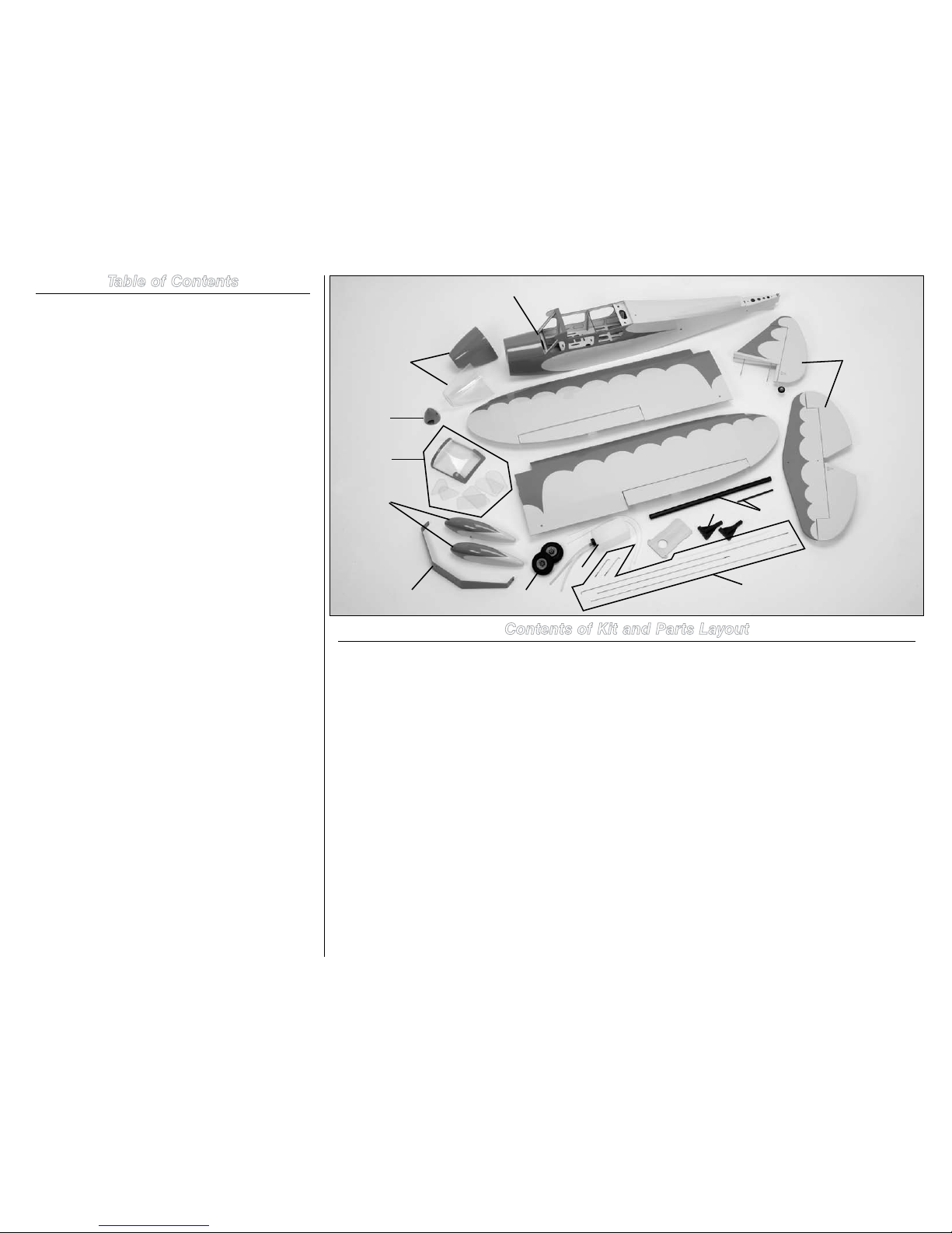
Contents of Kit and Parts Layout
1
2
3
4
5
6
7
8
9
14
10
11
12
13

3Hangar 9 Toledo Special Assembly Manual
Included Parts Listing
Fuselage (1)
Right wing with control horn (1)
Left wing with control horn (1)
Horizontal stabilizer with control horn (1)
Vertical fin with control horn (1)
Cowl with clear cowl template (1)
Aluminum landing gear (1)
Wheel pants (left and right) (2)
Front windshield (1)
Center window set (2)
Front window set (right and left) (2)
Rear window set (right and left) (2)
16
3
/8 x 5/8-inch anodized aluminum wing tube (1)
5 x 1/4-inch andozed aluminum anti-rotation tube (1)
FUSELAGE
4-40 x 3/8-inch socket head cap screw (3)
#4 flat fender washer (3)
Nylon clevis (1)
Pushrod keeper (1)
Clevis retainer (1)
Plywood throttle pushrod support (2)
MOTOR MOUNT
Small nylon motor mount (2)
48mm EP standoff (4)
8-32 x 2
1
/4-inch machine screw (EP) (4)
8-32 x 3/4-inch machine screw (4)
8-32 x 1-inch machine screw (4)
8-32 nylon lock nut (4)
#8 flat washer (8)
WING
20mm x 15mm x 8mm hardwood block (4)
#4 x 1/2-inch self-tapping washer head screw (8)
Nylon 1/4-20 x 1
1
/2-inch nylon wing bolt (2)
Nylon clevis (2)
Clevis retainer (2)
Pushrod keeper (2)
Wing bolt plate (1)
RUDDER
Nylon clevis (1)
Clevis retainer (1)
Pushrod keeper (1)
PUSHRODS
2
7
/8-inch pushrod (aileron) (2)
25
1
/2-inch pushrod (elevator) (1)
26-inch pushrod (rudder) (1)
16
1
/2-inch pushrod (throttle) (1)
12-inch nylon pushrod housing (throttle) (1)
LANDING GEAR
5/32 x 1
3
/8-inch axle with nut (2)
5/32 wheel collar (4)
3mm x 5mm machine screw (for wheel collar) (4)
4-40 x 3/8-inch socket head cap screw (2)
8-32 x 3/4-inch machine screw (3)
#4 flat washer (2)
#8 flat washer (3)
2
3
/4-inch rubber wheels (2)
COWL
2
1
/4-inch nylon spinner, blue (1)
#4 sheet metal screw (spinner screw) (2)
4-40 x 1/2-inch socket head cap screw (4)
#4 washer (4)
1/4-inch (6mm) fuel tubing (4)
ELEVATOR
4-40 nylon lock nut (2)
#4 flat fender washer (2)
Nylon clevis (1)
Clevis retainer (1)
Pushrod keeper (1)
MISCELLANEOUS
EP plywood battery tray (1)
Fuel tank assembly, 11 oz (1)
Nylon tie-wrap (2)
Velcro strap (2)
1.5mm hex wrench (1)
Using the Manual
This manual is divided into sections to help make assembly
easier to understand, and to provide breaks between each
major section. In addition, check boxes have been placed
next to each step to keep track of each step completed.
Steps with a single box () are performed once, while steps
with two boxes () indicate that the step will require
repeating, such as for a right or left wing panel, two servos,
etc. Remember to take your time and follow the directions.
UltraCote® Covering Colors
• Cream HANU878
• Sky Blue HANU875
Before Starting Assembly
Before beginning the assembly of your model, remove
each part from its bag for inspection. Closely inspect the
fuselage, wing panels, rudder and stabilizer for damage. If
you find any damaged or missing parts, contact the place of
purchase.
If you find any wrinkles in the covering, use a heat gun or
covering iron to remove them. Use caution while working
around areas where the colors overlap to prevent separating
the colors.
HAN100 – Heat Gun
HAN150 – Covering Glove
HAN101 – Sealing Iron
HAN141 – Sealing Iron Sock
The Spektrum trademark is used with permission
of Bachmann Industries, Inc.
4 Hangar 9 Toledo Special Assembly Manual
Radio Systems Requirements
Spektrum Radio System
• DX6i 6-channel radio or greater with receiver
(SPM6600)
• JRPS821 DS821 Digital Sport Servo (5)
(4 required for EP version)
• JSP98110 6-inch Servo Extension (2)
• JSP98020 Y-Harness or JSP98110 6-inch Servo
Extension (2) for receiver to aileron servos
• JR Switch, Chargeswitch (JRPA004)
• Receiver battery, 2700mAh
Optional
• JSP98020 Y-Harness or JSP98110 6-inch
Servo Extension to connect the float rudder
servo to the receiver.
Recommended Setup–2-Stroke Glow
• Evolution® .46NX with Muffler (EVOE0461)
• Evolution Propeller 11 x 5 (EVO11050) to
11 x 6 (EVO11060)
Recommended Setup–4-Stroke Glow
• Saito™ .82 AAC w/Muffler (SAIE082AGK or SAIE082A)
• Evolution Propeller 13 x 8 (EVO13080) or
14 x 6 (EVO14060)
Recommended Setup–
Electric Power (EP)
• E-flite® Power 46 BL Outrunner Motor (EFLM4046A)
• 60-Amp Pro Switch-Mode BEC Brushless ESC
(EFLA1060)
• Thunder Power 4S 3850–4500mAh LiPo Battery Pack
• APC Propeller 13x6.5-inch (APC13065E) to
14x7 (APC14070E)
Field Equipment Required
• Fuel (15% recommended)
• Propeller
• Long Reach Glow Plug Wrench (HAN2510)
• Metered Glow Driver w/Ni-Cd & Charger (HAN7101)
• 2-Cycle Sport Plug (EVOGP1)
• Manual Fuel Pump (HAN118)
Optional Field Equipment
• Self-stick weights, 6 oz (HAN3626)
• PowerPro 12V Starter (HAN161)
• 12V 7Ah Sealed Battery (HAN102)
• Power Panel (HAN106)
• Blue Block After Run Oil (EVOX1000)
• Cleaner and towels
Additional Required Tools
Drill File
Pin drill Pliers
Ruler Scissors
Side cutters Flat blade screwdriver
Hobby knife with #11 blade Small clamps
Medium grit sandpaper Z-bend Pliers (HAN119)
Phillips screwdriver: #1, #2 Hook and loop tape
Low-Tack Tape (MMM209034)
Box wrench to fit propeller nut
Box end or open end wrench: 1/4-inch, 7/16-inch,
1/2-inch
Hex wrench or ball driver: 3/32-inch
Drill bit: 5/64-inch (2mm), 5/32-inch (4mm)
Additional Required Adhesives
Canopy Glue (PAAPT56)
Medium CA (PAAPT02)
Thin CA (PAAPT08)
Threadlock (PAAPT42)
30-Minute Epoxy, 8 oz (PAAPT39)
FS One®
With FS One (HANS2000) you get more than photorealistic
fields, gorgeous skies and realistic-looking aircraft. You get
incredibly advanced aerodynamic modeling that simulates
every possible aspect of real-world flight.
The first Hangar Pack
®
(HANS4010) will add even more
aircraft to FS One. This latest edition includes ten new planes
and helis from your favorite brands, including Hangar 9,
E-flite and Align. You’ll be able to fly aircraft that are only
available on FS One such as the T-REX, Blade CX2, Blade CP
Pro, Hangar 9 P-51 and F-22 PTS. And as always, with the
Hangar Pack, you still get all the same great features that
you did with the original aircraft.
HANS2008 HANS4010
Important Information
Regarding Warranty Information
Please read our Warranty and Liability Limitations section on
Page 33 before building this product. If you as the purchaser
or user are not prepared to accept the liability associated
with the use of this Product, you are advised to return this
Product immediately in new and unused condition to the
place of purchase.
5Hangar 9 Toledo Special Assembly Manual
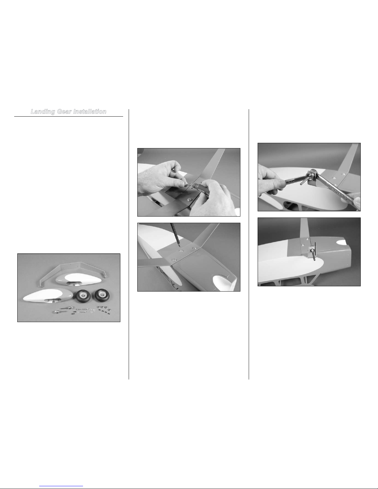
Landing Gear Installation
Required Parts
Fuselage assembly #4 washer (2)
#8 washer (3) Main landing gear
Wheel axle with nut (2) 5/32-inch wheel collar (4)
Wheel pant (right and left)
Wheel, 2
3
/4-inch (70mm) (2)
3mm x 5mm machine screw (4)
8-32 x 3/4-inch machine screw (3)
4-40 x 3/8-inch socket head screw (2)
Tools and Adhesives
Phillips screwdriver: #1, #2 Threadlock
Flat file
Box wrench: 7/16-inch, 1/2-inch
Hex wrench or ball driver: 3/32-inch
Step 1
Locate the main landing gear, wheels, wheel pants and the
bag marked landing gear. Open all the part bags and set the
parts where they can be easily accessed.
Step 2
The main landing gear is mounted to the bottom of the
fuselage using three 8-32 x 3/4-inch machine screws and
three #8 washers. Apply a drop of threadlock on each of the
screws. Use a #2 Phillips screwdriver to tighten the screws
to secure the landing gear to the bottom of the fuselage.
Step 3
Attach the wheel axle to the landing gear using a 7/16-inch
box wrench (axle) and 1/2-inch box wrench (nut). Make
sure the nut on the axle side aligns with the landing gear as
shown in the photo so the wheel pant can be installed.
6 Hangar 9 Toledo Special Assembly Manual
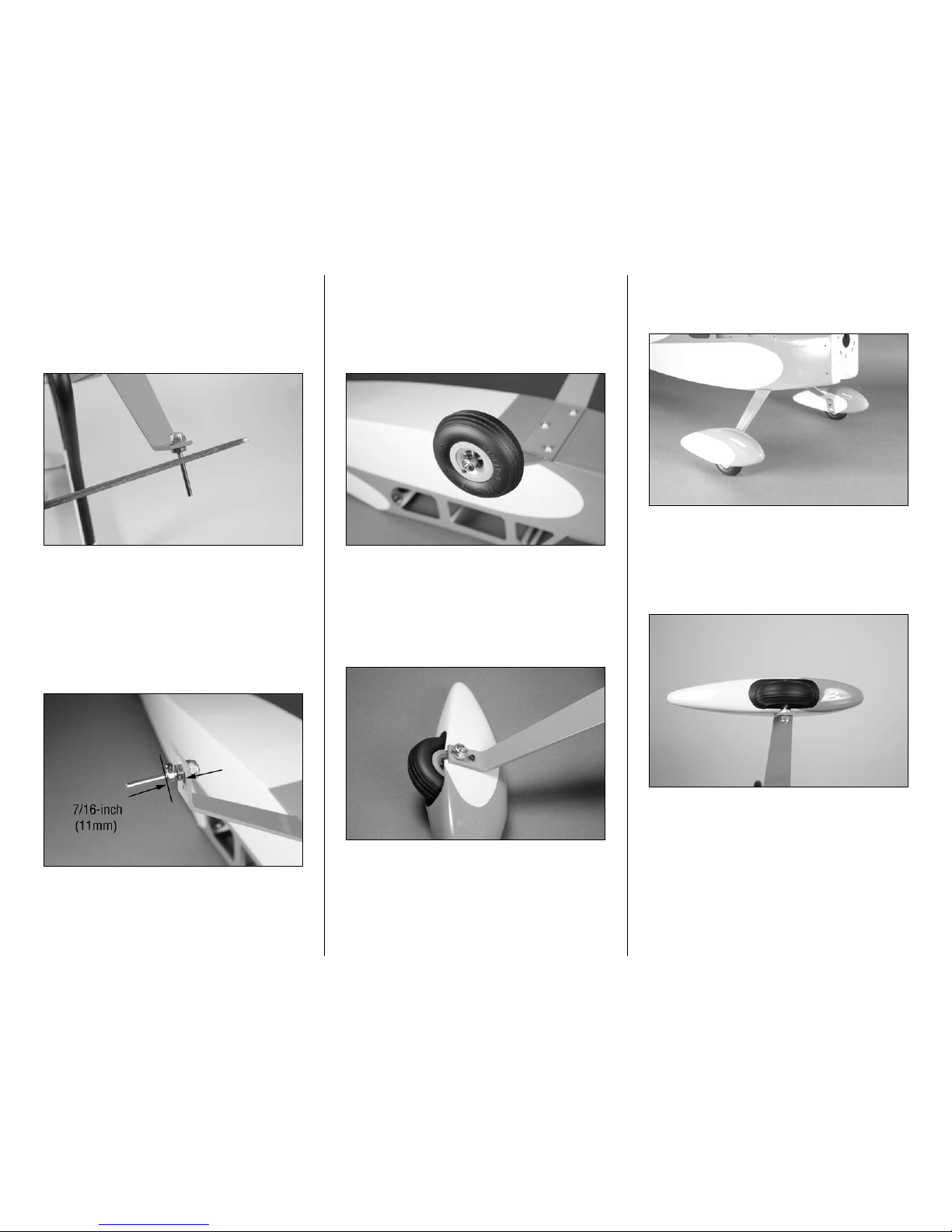
Step 4
Use the narrow edge of a flat file to make two flat spots on
the wheel axle that faces the bottom of the fuselage. These
will be the areas that the screws for the wheel collars will
tighten into. The flat areas will keep the wheel collars more
secure than if the axle were round.
Step 5
Attach a 5/32-inch wheel collar to the axle using a 3mm x
5mm machine screw. Make sure to apply threadlock to the
screw so it will not vibrate loose. Position the collar so it is
7/16-inch (11mm) from the landing gear as shown and use
a #2 Phillips screwdriver to tighten the screw on the flat area
of the axle. The position of the wheel may need to be be finetuned in the last step of this section.
Step 6
Slide the wheel on the axle. Use a 5/32-inch wheel collar and
a 3mm x 5mm machine screw to secure the collar. Make
sure to position the collar so the wheel can rotate freely on
the axle. Use a #2 Phillips screwdriver to tighten the screw
on the flat area of the axle.
Step 7
Slip the wheel pant over the wheel. The wheel pant is
secured to the landing gear using a 4-40 x 3/8-inch socket
head screw and #4 washer. Apply a drop of threadlock on the
screw before using a 3/32-inch hex wrench or ball driver to
tighten the screw.
Step 8
Repeat Steps 3 through 7 to install the remaining wheel and
wheel pant.
Step 9
Position the wheels so they are centered side to side
inside the wheel pant. You will need to loosen the wheel
collars to do so. Also make sure the wheel can rotate
freely without binding.
Hint: Apply a small drop of lightweight oil to help the
wheels to roll smoothly.
7Hangar 9 Toledo Special Assembly Manual
Tail Installation
Required Parts
Fuselage assembly Horizontal fin assembly
Vertical fin assembly #4 fender washer (2)
4-40 lock nut (2)
Tools and Adhesives
Nut driver or box wrench: 1/4-inch
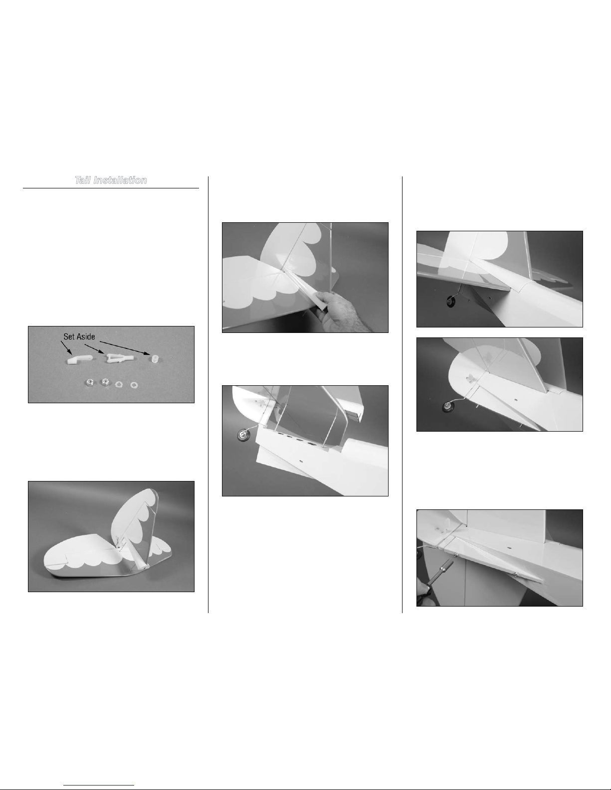
Step 1
Open the bag marked elevator. Set aside the clevis, clevis
retainer and pushrod keeper for installation in the next
section of the manual.
Step 2
Locate the vertical and horizontal stabilizers. Slide the
threaded rods from the vertical stabilizer through the holes
in the horizontal stabilizer. Make sure the blue trim on the
horizontal stabilizer faces up toward the vertical stabilizer as
shown in the photo below.
Step 3
Slide the horizontal and vertical stabilizers tightly together
as shown. You will need to deflect the rudder to allow the
rudder control horn to pass by the elevator.
Step 4
Slide the threaded rods into the holes in the aft end of the
fuselage as shown.
Step 5
Slide the tail assembly tightly against the fuselage. Make
sure to guide the portion of the vertical stabilizer with the tail
wheel carefully into the slot at the rear of the fuselage so the
fuselage is not damaged by side loads.
Step 6
Secure the tail assembly to the fuselage using two #4 fender
washers and two 4-40 lock nuts. Use a 1/4-inch nut driver
or box wrench to tighten the nuts. Make sure not to overtighten the nuts and accidentally damage the sub-fin or
fuselage.
8 Hangar 9 Toledo Special Assembly Manual
Radio Installation
Required Parts
Fuselage assembly Receiver
Receiver battery Switch harness
Hook and loop strap Radio foam
Y-harness (1) or 6-inch (152mm) servo extension (2)
Servo with hardware (3)
(2 if constructing the EP version)
Tools and Adhesives
Phillips screwdriver: #1 Thin CA
Hobby knife with #11 blade Hook and loop tape
Scissors
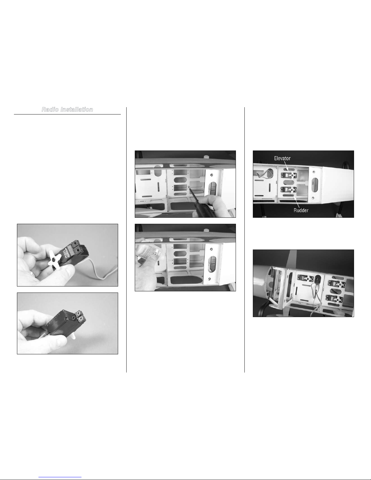
Step 1
Install the grommets and brass eyelets in three servos for
the elevator, rudder and throttle.
Note: If you are building the EP version, you only need to
prepare two servos for rudder and elevator at this time.
Step 2
Use a #1 Phillips screwdriver to thread a servo mounting
screw into the holes in the radio tray for mounting the
servos. Apply a drop or two of thin CA into each hole to
harden the threads made by the screw. This will provide a
much more secure mounting of the servos than if this step
were skipped.
Step 3
Use the hardware to mount the rudder and elevator servos in
the servo tray. Make sure the output of the servos face to the
rear of the fuselage. Tighten the screws using a #1 Phillips
screwdriver. Make sure to guide the leads from the servos
through the hole behind the opening for the throttle servo
when placing the servos in the radio tray.
Step 4
Mount the throttle servo in the radio tray as shown using a #1
Phillips screwdriver and the screws provided with the servo.
Note: If you are building the EP version you will not
need to install the throttle servo.
9Hangar 9 Toledo Special Assembly Manual
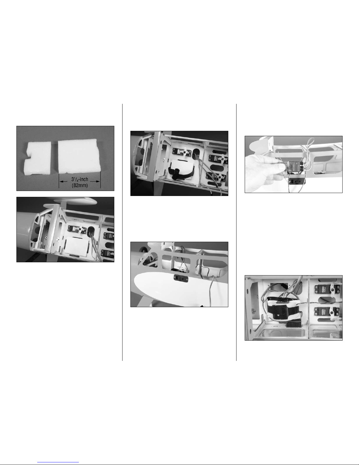
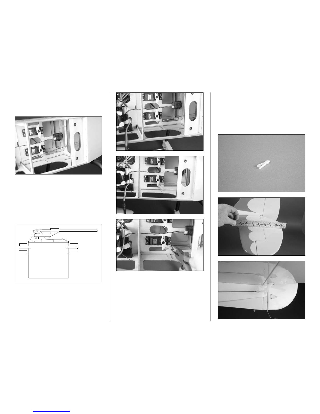
Step 5
Measure and cut a 31/4-inch piece of foam from the supplied
foam blocks using scissors.
Note: Use only a few drops of CA so the foam can be
removed if it ever needs to be replaced.
Step 6
Open the bag marked Misc and remove one of the hook and
loop straps. Insert the strap through the slots as shown in
the photo.
Step 7
There are two different holes in the side of the fuselage that
should match your particular switch. Use a hobby knife to
remove the covering from the appropriate hole. Mount the
switch harness in the side of the fuselage using the hardware
provided with your switch.
Note: Do not cut any switch locations if you are
building the airplane and installing an electric motor.
This will be covered in the Electric Motor Installation
starting on Page 20.
Step 8
Plug the rudder, elevator and throttle servos into the receiver.
The lead from the switch should also be plugged in at this
time. Finally, plug the Y-harness or 6-inch (152mm) servos
extensions for the aileron servos into the receiver.
Note: When using two 6-inch (152mm) extensions,
you will need to use a computer radio with dual aileron
mixing or programmable mixing. Plug the extensions
into the aileron channal and the AUX channel that
corresponds to the opposite aileron channel.
Step 9
Connect the receiver battery to the switch harness. Place
the battery on the foam, then place a piece of foam on the
battery. The receiver mounts on the battery with a piece of
foam between the receiver and hook and loop strap, and
everything is secured by the hook and loop strap installed
in Step 6.
Note: EP version shown without throttle servo
installed. Glow receiver installation is identical.
10 Hangar 9 Toledo Special Assembly Manual
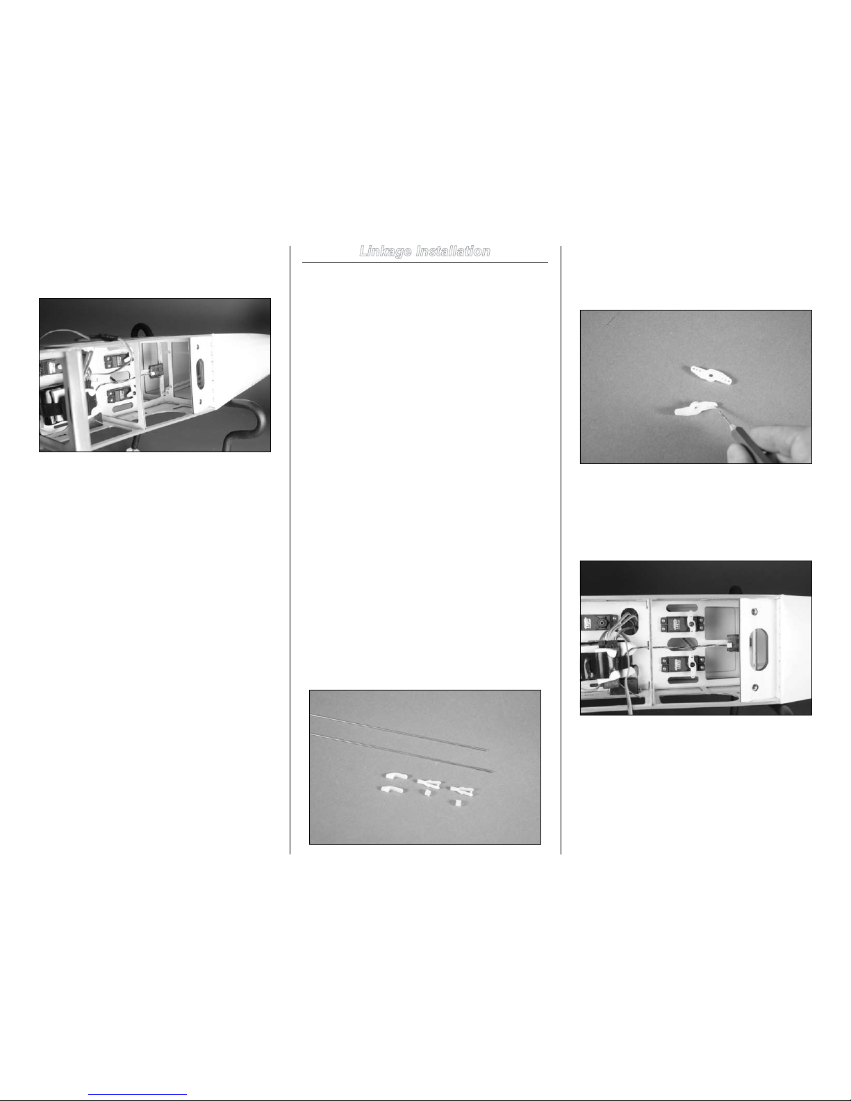
Step 10
Use a piece of hook and loop tape (not included) to mount
the remote receiver at the rear of the servo tray as shown.
Linkage Installation
Required Parts
Fuselage assembly Transmitter
Clevis (2) Clevis retainer (2)
Pushrod keeper (2) 26-inch pushrod (rudder)
25
1
/2-inch pushrod (elevator)
180-degree servo horn (2)
Tools and Adhesives
Phillips screwdriver: #1 Pin drill
Drill bit: 5/64-inch (2mm) Ruler
Pliers
Step 1
Start with a new model if you are using a computer radio,
Make sure the trims and sub trims are set to 0 and there
are no mixing options turned on as well. Check the radio
system by turning on the receiver and transmitter. It may
be necessary to bind the transmitter and receiver if you are
using a new receiver. Follow the instructions provided with
your radio system regarding binding if necessary. Remove
the horns from the servos inside the fuselage at this time
using a #1 Phillips screwdriver.
Step 2
Open the bag marked rudder and remove the clevis, clevis
retainer and pushrod keeper. You will also need these three
items that were in the bag marked elevator. You will also
need to remove the 251/2-inch elevator pushrod and 26-inch
rudder pushrod from the bag marked pushrod set for this
section of the manual.
Step 3
Locate two 180-degree servo horns. Enlarge the holes that
are 9/16-inch (14mm) from the center of the horn as shown
using a pin drill and 5/64-inch (2mm) drill bit.
Step 4
With the radio system on and the trims (and sticks)
centered, attach the servo horns to the rudder and elevator
servos. Use the screws from the servo and a #1 Phillips
screwdriver to secure the horn.
Hint: Most servos have an odd number of splines. If
the horn is not aligned correctly as shown, you can
rotate it 180 degrees to bring it into alignment.
11Hangar 9 Toledo Special Assembly Manual
Step 5
Slide the 26-inch rudder pushrod into the tube in the
fuselage. Make sure to use the upper tube, as the tube below
it is for use to route the antenna for a 72MHz receiver.
Step 6
Insert the bend on the pushrod wire through the hole in the
servo horn that was enlarged in Step 3. Slide the pushrod
keeper onto the portion of the wire below the servo horn.
The keeper is then rotated and snapped on the pushrod to
secure the connection between the servo horn and pushrod.
You may need to use pliers to snap the connector in
position.
Step 7
Repeat Steps 5 and 6 to install the 251/2-inch elevator
pushrod and secure it to the elevator servo horn.
Hint: If you have larger hands, you can always remove
the servo horns to make the connections outside the
fuselage. Just remember to orient the servo horns the
same as they are inside the fuselage so they remain
aligned when reinstalled on the servos.
Step 8
Slide a clevis retainer on one clevis. Thread the clevis on the
elevator pushrod wire. With the radio system on, connect
the clevis to the center hole of the elevator control horn.
Use a ruler to check that the elevator and stabilizer are in
alignment. If not, you will need to thread the clevis in or out
so when the elevator servo is centered, the elevator is in
alignment at the same time.
 Loading...