

Hangar 9 Taylorcraft 20cc ARF Assembly Manual

Taylorcraft 20cc ARF
Assembly Manual
Specifications
Wingspan: ..........................................................................................80.5 in (2045.5mm)
Length: ..................................................................................................63.7 in (1618mm)
Wing Area: ............................................................................1152.73 sq in (74.4 sq dm)
Weight: .....................................................................................13-14.5 lb (5.90-6.58 kg)
Radio: ..........................................................................................4-channel w/6 servos
Engine: ....................1.00–1.60 2-stroke; 1.20–1.80 4-stroke; 20–26cc gas; Power110
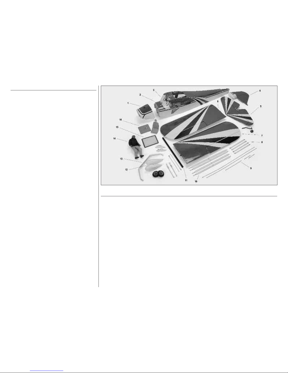
Table of Contents
Contents of Kit and Parts Layout............................................2
Included Hardware.................................................................3
Using the Manual....................................................................4
UltraCote Covering Colors......................................................4
Before Starting Assembly........................................................4
Workspace Preparation..........................................................4
Radio SystemRequirements..................................................4
Recommended Power Setups................................................4
Important Information Regarding Warranty.........................4
Required Tools and Equipment......................................5
RequiredAdhesives................................................................5
Other Required Items.............................................................5
Product Registration...............................................................5
Rudder and Elevator Servo Installation..................................6
Tail Installation........................................................................7
Elevator Pushrod and Rudder Pull-Pull Cable Installation....9
Tailwheel Installation.............................................................14
Tail Brace Installation............................................................16
Landing Gear Installation......................................................19
Gas Engine Installation.........................................................21
Ignition and Engine Installation.............................................25
Throttle Servo, Linkage & Carburetor Installation................27
Cowling Installation...............................................................30
Fuel System Connections.....................................................33
Aileron Servo Installation......................................................34
Wing Strut Assembly.............................................................38
Radio Installation..................................................................41
IgnitionBattery Installation....................................................43
Windshield and Landing Gear Cuff Installation....................44
FinalAssembly......................................................................45
Center of Gravity...................................................................48
Control Throws.....................................................................49
Flight Preparations................................................................49
Maintaining Your Model........................................................50
Safety Do’s and Don’ts for Pilots..........................................51
Dual Rate..............................................................................51
Age Requirements................................................................51
Daily Flight Checks...............................................................51
Safety, Precautions and Warnings.......................................52
Warranty Information............................................................52
2009 Official Academy of
ModelAeronautics Safety Code............................55
2
Hangar 9 Taylorcraft 20cc Assembly Manual
Contents of Kit and Parts Layout
Replacement Parts
1. HAN4907 Cowl
2. HAN4901 Fuselage with Top Hatch
3. HAN4906 Windshield
4. HAN4913 Fin and Rudder
5. HAN4905 Stabilizer
6. HAN4903 Left Wing Panel
7. HAN4904 Right Wing panel
8. HAN4909 Stabilizer Strut Parts
9. HAN4917 Pushrods
10. HAN4911 Wing Strut Assembly LR
11. HAN4910 Wing Tube
12. HAN4912 Wheel Pants
13. HAN4908 Landing Gear
14. HAN4566 Pilot
15. HAN4902 Top Window
16. HAN4915 Seat and Mounting Panel
Not Illustrated
HAN4914 Engine Standoffs for G20EI
HAN4916 Small Parts Bag

3
Hangar 9 Taylorcraft 20cc Assembly Manual
Included Hardware
Packaged in Kit
Fuselage (1)
Right Wing with aileron & control horn (1)
Left Wing with aileron & control horn (1)
Fin with rudder & control horn (1)
Stabilizer with elevators & control horns (1)
Cowling (1)
Windshield (1)
Wheel pants (pair) (1)
Landing gear (1)
3-inch Pro-Lite wheel (2)
Window and Seat Bag
Top window (1)
#4 x 1/4-inch screw (12)
Seat (1)
Radio compartment cover (1)
22-inch hook & loop strap (1)
Landing Gear Bag
Simulated springs (2)
Landing gear cuffs (2)
6-32 x 3/4-inch button head hex screw (6)
6-32 x 1/2-inch button head hex screw (4)
#6 steel washers (12)
6-32 nylon lock nut (2)
5/16-inch wheel collars (2)
3mm x 6mm socket head cap screws (4)
7/64-inch Allen wrench (1)
4-40 x 1/2-inch socket head cap screw (4)
#4 steel washers (4)
1 3/4-inch axle with nut (2)
Aileron Bag
#2 x 1/4-inch self-tapping screws (8)
20mmx 20mm x 10mm hardwood block (4)
Fuel Tank Bag
17oz assembled fuel tank (1)
#64 rubber band (2)
Aluminum fuel line stopper (1)
Engine Mount Bag
28mm Aluminum standoff (4)
8-32 x 1 1/2-inch button head Allen screw (4)
8-32 x 1 1/4-inch machine screw (4)
8-32 x 3/4-inch button head Allen screw (4)
8-32 blind nut (4)
8-32 nylon lock nut (4)
#8 steel washers (8)
Aluminum engine mount (2)
4-40 x 1/2-inch button head Allen screw (4)
#4 steel washer (4)
Tailwheel Bag
Tailwheel assembly with wheel (1)
Springs (2)
Tiller arm (1)
#2 x 5/8-inch self-tapping screws (2)
#4 x 3/4-inch socket head wood screws
(2)
#4 steel washers (2)
Tail Flying Wire Bag
Bottom strut supports (4)
Top flying wire (2)
4-40 steel rod end (2)
4-40 hex nut (2)
4-40 x 1/4-inch button head Allen screw (4)
4-40 x 5/8-inch button head Allen screw (5)
#4 steel washers (6)
Brass tab (2)
Aluminum tab (1)
Control Hardware Bag
89-inch coated control cable (1)
4-40 steel clevis (6)
4-40 rigging coupler (4)
4-40 hex nut (6)
6-32 x 1-inch button head Allen screw (4)
#6 steel washer (4)
Copper crimp (4)
Nylon clevis (1)
Snap link (1)
2-56 ball link with hardware (1)
4-40 ball link with hardware (6)
1/4-20 x 1 1/2-inch nylon bolt (2)
Silicone clevis keepers (10)
Strut Hardware Bag
4-40 x 3/8-inch button head Allen screw (4)
4-40 x 1/2-inch button head Allen screw (4)
4-40 x 5/8-inch socket head cap screw (4)
4-40 nylon lock nut (8)
#4 steel washer (4)
5mm hex nut (4)
Silicone pin spacer (4)
Strut pin & keeper (4)
Strut end (4)
Strut bracket (fuselage) (2)
Strut bracket (wing) (4)
Jury strut fitting (4)
Jury strut (6)
Forward strut (2)
Rear strut (2)
Pushrod Bag
4-40 x 32 1/4-inch pushrod (2)
4-40 x 4 5/16-inch pushrod (2)
2-56 x 13-inch pushrod (1)
8-inch nylon pushrod housing (1)
21 3/4 x 3/4-inch aluminum wing tube (1)

4
Hangar 9 Taylorcraft 20cc Assembly Manual
Using the Manual
This manual is divided into sections to help make
assembly easier to understand, and to provide breaks
between each major section. In addition, check boxes
have been placed next to each step to keep track of
completed sections. Steps with a single box () are
performed once, steps with two boxes () indicate
that the step needs to be repeated, such as for left
and right wing panel, or two servos etc.
Before beginning it is a good idea to read through the
manual completely to familiarize yourself with the
assembly process. Remember to take your time and
follow the directions.
UltraCote®Covering Colors
● White HANU870
● Black HANU874
● True Red HANU866
● 2-inch squares, Red/White HANU944
Before Starting Assembly
Before beginning the assembly of your model, remove
each part from its bag for inspection. Closely inspect
the fuselage, wing panels and tail section for
condition. If you find any damaged or missing parts
contact the place of purchase.
Any wrinkles in the covering can be removed with a
heat gun or covering iron. Use caution while working
around edges and areas where colors overlap to
prevent separating the covering.
Workspace Preparation
During the course of building your Taylorcraft we
suggest that you use a soft base on the building
surface. Such things as a foam stand, large piece of
bedding foam or a thick bath towel will work well and
help protect the model from damage during assembly.
A flat area measuring at least 24 x 72-inches is
required to work on the model sub-assemblies
comfortably. The completed and assembled model
requires a space of 72 x 90-inches. Ensure you have
adequate lighting, and a place to set aside parts that
have been completed.
Radio System Requirements
Spektrum Radio System
● DX7 7-channel radio with receiver (SPM2710)
● JRPS821 DS821 Digital Sport servo (5)
● JRPS537 Standard servo for throttle
(not required for EP version)
● JRPA098 12-inch servo extension (4)
● JRPA004 Deluxe Chargeswitch
● JRPB5008 2700mAh receiver battery
Optional Item
● 2-1/2" Aluminum Spinner (TRU2502B120)
Recommended Setup–Gas
● Zenoah G20EI (ZENE20EI)
● Evolution propeller 16x6 (EVO16060)
● Deluxe Chargeswitch (JRPA004)
● Ignition Battery 4500mAh (JRPB5004)
● Gas fuel tubing (DUB799)
Recommended Setup–Electric
● E-flite Power 110 (EFLM4110A)
● Phoenix HV-85 ESC (CSEPHX85HV)
● Thunder Power 4S 5000mAh Li-Po (2)
● APC Propeller 18x8E (APC18080E)
Recommended Setup–2-stroke Glow
● Evolution 1.20NX with muffler (EVOE1200)
● Evolution propeller 16x6 (EVO16060)
Recommended Setup–4-stroke Glow
● Saito FA-125A (SAIE125A)
● Evolution propeller 16x6 (EVO16060)
Important Warranty Information
Please read our Warranty and Liability Limitations section
on Page 52 before assembling this product. If you as the
purchaser are not prepared to accept the liability
associated with the use of this Product, you are advised
to return this Product immediately in new and unused
condition to the place of purchase.
5
Hangar 9 Taylorcraft 20cc Assembly Manual
Required Tools and Equipment
Drill Pin vise
Low-tack tape Pliers
Ruler Sidecutters
File Felt-tipped pen
Pencil Medium grit sandpaper
Tapered reamer Hobby knife (#11 blade)
Dental floss Manila card stock
Alcohol Paper towels
Crimping pliers Double-sided adhesive tape
Mixing sticks Mixing cups
Needle nose pliers Scissors
Rotary tool with sanding drum
Cable ties: small (4-inch), medium (7-inch)
Phillips screwdriver: #0, #1
Hex wrench or balldriver: 5/64, 3/32, 1/8-inch
: 1.5, 2.5, 3, 4mm
open-end wrench: 3/16, 1/4, 9/32, 5/16-inch
: 10, 13mm
Drill bit: 1/32, 11/64, 3/32, 11/64, 3/16, 13/64,1/4-inch
Required Adhesives
Thin CA (PAAPT08)
Medium CA (PAAPT02)
12-minute epoxy (HAN8001)
Threadlock (PAAPT42)
Canopy glue (PAAPT56)
Other Required Items
12-inch extension leads (JRPA098) (4)
Fuel dot filler (HAN115)
Heavy-duty servo arms (JRPA215)
1/4-inch foam rubber (DUB513)
Product Registration
Horizon Hobby wants to ensure that you get
maximum enjoyment from your Hangar 9 products.
We strongly encourage you to register your product
using the online Product Registration tool so we can
notify you when there are service bulletins, new option
parts or accessories, or updates available for your
product.
Register your product today at:
http://www.hangar-9.com/Register/
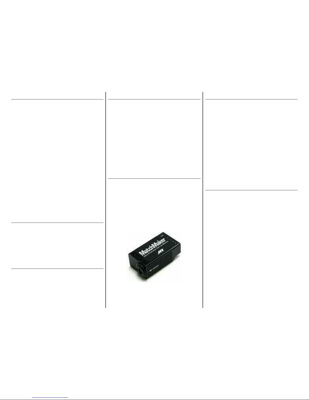
Optional Accessory
Setting up servos is a whole lot easier with a JR
®
MatchMaker™. It lets you accurately center servos,
evaluate endpoints, and cycle servos at varying
speeds, without ever having to switch on a transmitter.
It allows the precise digital centering of up to 2 servos
at a time to help with setup on the building bench.
Work Area Cleanliness
It is a good practice to maintain a clean work area,
both to prevent damage to your model and to keep
track of parts and hardware. Put away any tools not
being used, and set aside parts of the model that are
not being worked on.
Of special importance is keeping debris out of
sensitive components such as the radio and engine or
motor. Tape over engine intake and exhaust ports
when drilling or cutting the firewall and cowling to
prevent causing damage to the internal components.
Hardware Practices
When installing hardware that consists of a button
head machine screw, washer and nut, use an openended or box wrench to tighten the nut while holding
the fastener with a hex wrench. The washer provides
a bearing surface for the nut while it is being turned,
holding the screw with a wrench prevents damage to
the part, particularly on painted components.
6
Hangar 9 Taylorcraft 20cc Assembly Manual
Rudder and Elevator Servo
Installation
Required Parts
Fuselage Servos with hardware (3)
Required Tools
Thin CA #1 Phillips screwdriver
Step 1
Open the cockpit door by pulling on the handle. The
door is held closed with magnets, the handle does not
need to be turned.
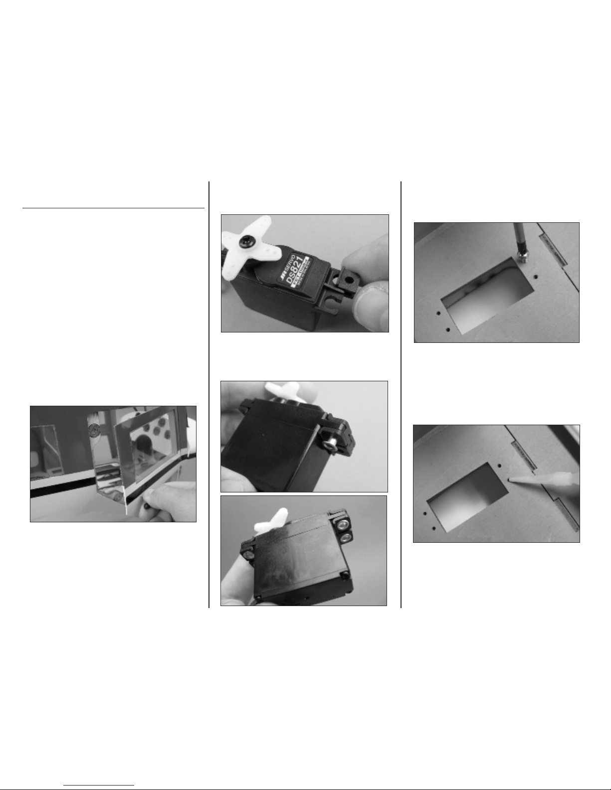
Step 2
Insert the rubber grommets into the servos.
Step 3
Insert the brass bushings in the servos. Note that the
flange is located on the lower side of the servo.
Step 4
Use a #1 Phillips screwdriver to install a servo screw
in each of the pre-drilled holes in the servo tray.
Step 5
Remove the servo screw and apply a drop of thin CA
in each hole to strengthen the wood.
7
Hangar 9 Taylorcraft 20cc Assembly Manual
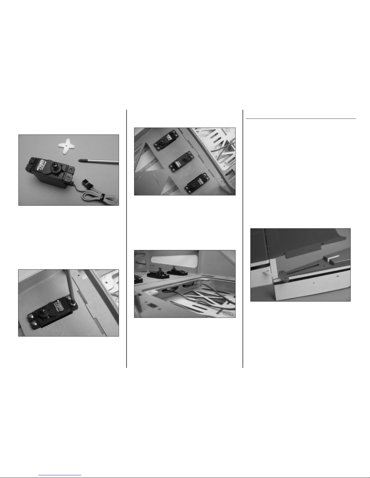
Step 6
Use a #1 Phillips screwdriver to remove the stock
servo arms from the servos. Replace the servo screw.
Step 7
Use a #1 Phillips screwdriver to install the rudder and
elevator servos. The elevator servos (outer locations)
have the output shaft towards the tail, the rudder servo
mounts in the center with the output shaft forward.
Step 7
This shows the rudder and elevator servos installed.
Step 8
Route the servo leads forward into the radio
compartment through the holes in the bulkhead.
Tail Installation
Required Parts
Fuselage Fin with rudder
Stabilizer with elevators
Required Tools
Threadlock 3/32-inch hex wrench
Step 1
Engage the fin post in the slot in the rear of the
fuselage behind the hold-down plate.
8
Hangar 9 Taylorcraft 20cc Assembly Manual
Step 2
Slide the fin down until it is fully engaged in the
fuselage slots.
Step 3
Separate the stabilizer halves from each other.
Step 4
Slide the stabilizer joiner rods through the holes in the
base of the fin and slide the stabilizer halves against
each side of the fin.
Step 5
Locate the four 6-32 x 1-inch button head hex bolts.
Place a drop of threadlock on the end of the threads.
Step 6
Use a 3/32-inch hex wrench to install the four
stabilizer bolts. Use care to not tighten the bolts
excessively and crush the stabilizer structure.
9
Hangar 9 Taylorcraft 20cc Assembly Manual
Elevator Pushrod and Rudder
Pull-Pull Cable Installation
Required Parts
Fuselage Elevator pushrods (2)
4-40 hex nut (6) Pull-pull cable
4-40 clevis (6) 4-40 ball link (6)
Copper crimp (4) 4-40 rigging coupler (4)
HD servo arm 180-degree servo arm (2)
Required Tools
Pin vise 3/32-inch drill bit
1/4-inch wrench 5/64-inch hex wrench
Threadlock Pliers
Sidecutters Crimping pliers
3/16-inch wrench
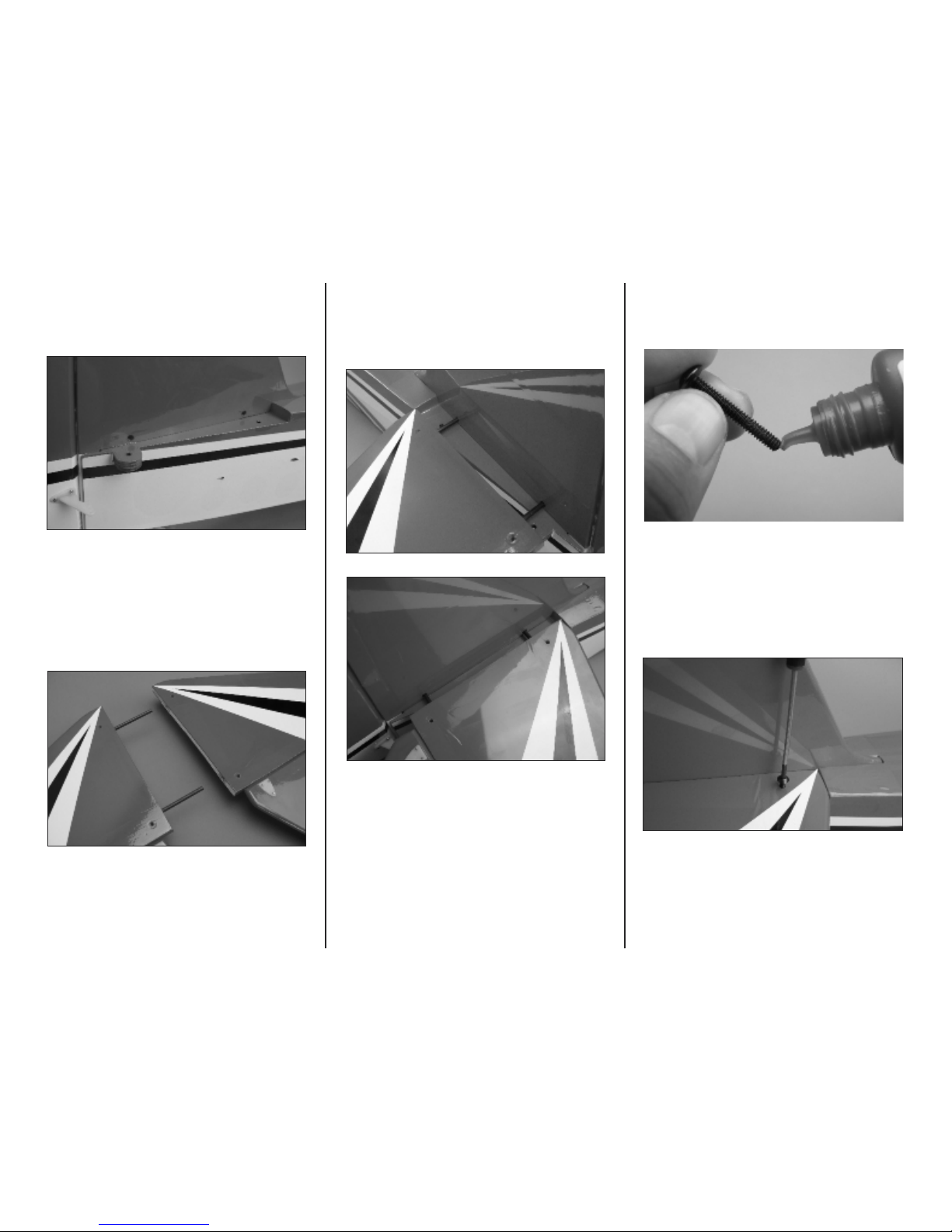
Step 1
Prepare the elevator pushrods by threading a 4-40
hex nut and 4-40 clevis onto one end.
Step 2
Insert the elevator pushrod into the pushrod housing
opening in the rear of the fuselage side.
Step 3
Use a 3/32-inch drill bit in a pin vise to enlarge the
outer hole in a standard 180 degree servo arm.
Step 4
Use a 5/64-inch hex driver and 1/4-inch wrench to
install a 4-40 ball link onto the servo arm.
Step 5
Thread the ball link and servo arm onto the servo end
of the elevator pushrod until approximately 3/8-inch of
thread remains exposed.
10
Hangar 9 Taylorcraft 20cc Assembly Manual
Step 6
Use your radio or a JR MatchMaker to center the
elevator servo and install the servo arm using a #1
Phillips screwdriver.
Step 7
Adjust the clevis so that the elevator is centered when
connected to the center hole in the elevator horn.
Step 8
Use a ruler to check the alignment of the elevator with
the stabilizer as the clevis is being adjusted.
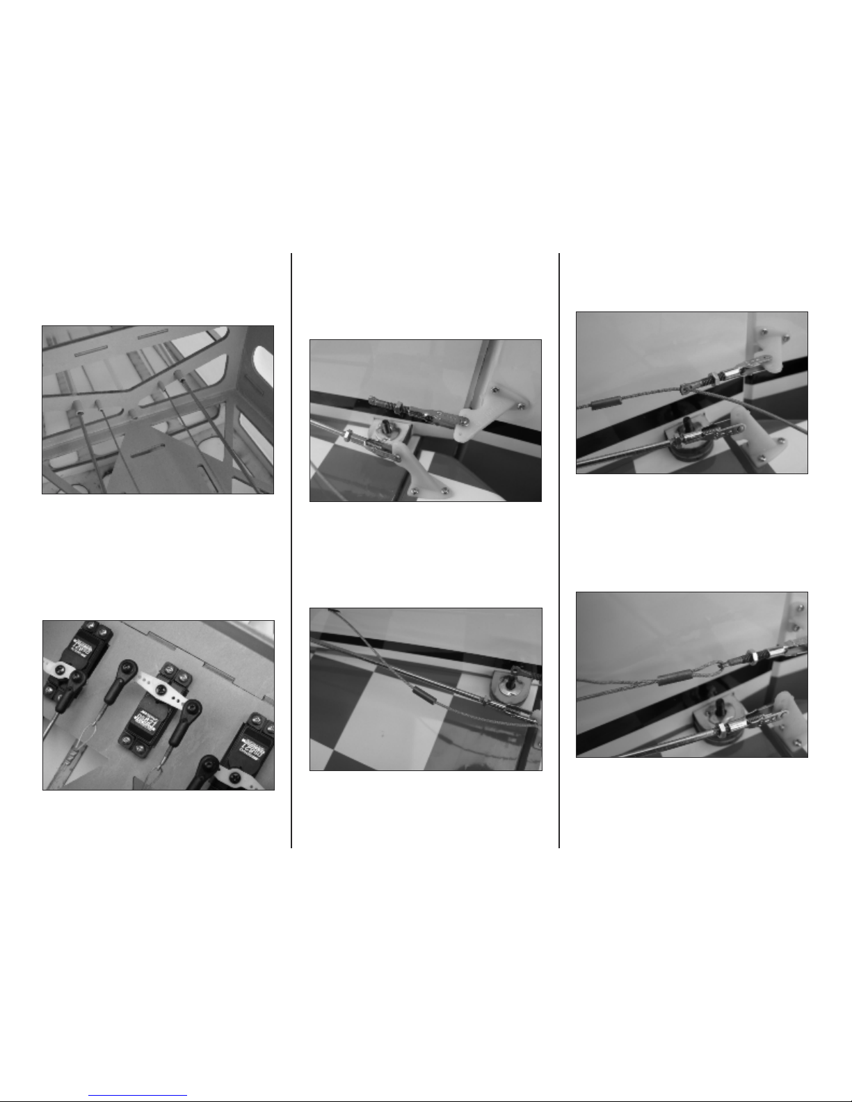
Step 9
Locate the coil of coated steel pull-pull cable. Uncoil
the cable and fold it against itself to find the center.
Use sidecutters to cut the cable into two equal lengths.
Step 10
Use a hobby knife with a #11 blade to debur the inside
of each end of the copper crimp. This will make it easier
to double the cable through the crimp.
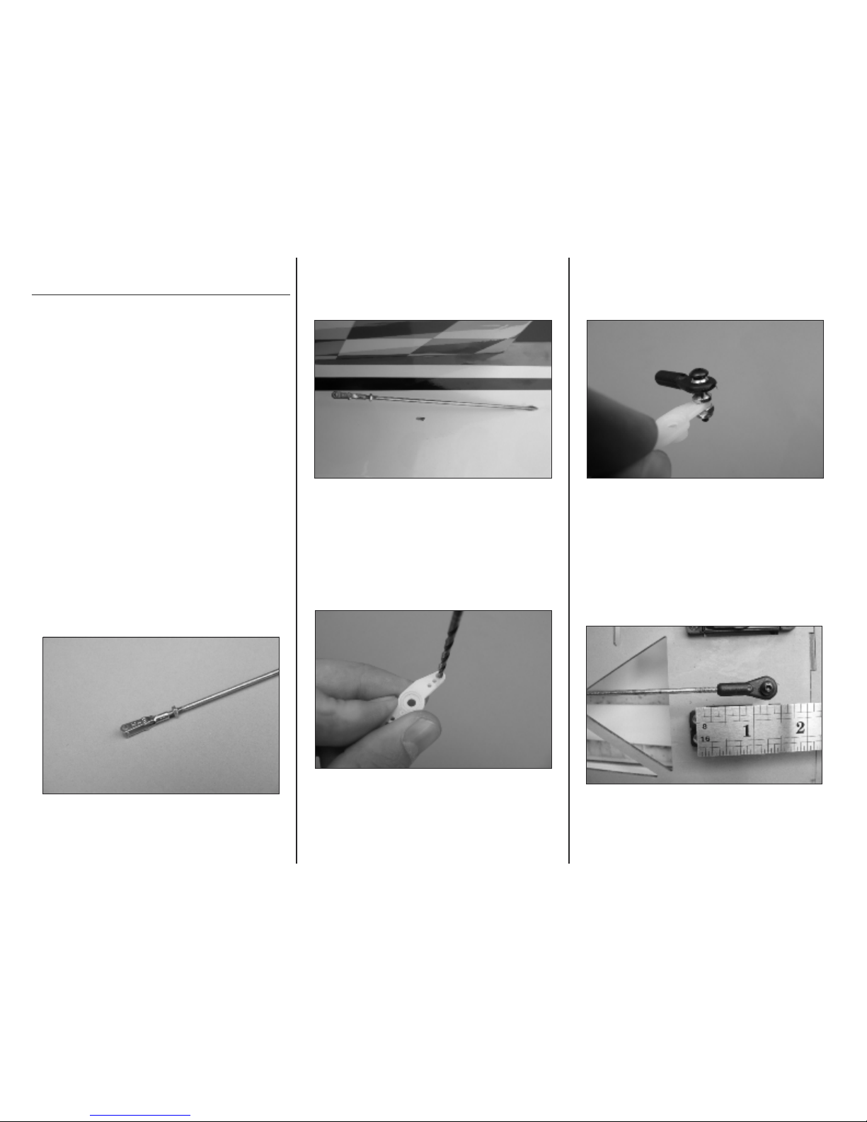
Step 11
Slide a copper crimp onto the end of the pull-pull
cable.
11
Hangar 9 Taylorcraft 20cc Assembly Manual
Step 12
Slide a 4-40 rigging coupler onto the cable next to the
copper crimp.
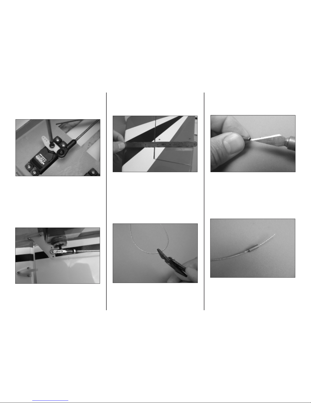
Step 13
Fold the cable back on itself and insert the free end
through the copper crimp. Form a loop approximately
5/8-inch long containing the rigging coupler, and leave
about 3/16-inch protruding from the crimp.
Step 14
Use crimping pliers or sidecutters on the copper crimp
to secure the cable end. Use care not to cut
completely through the cable.
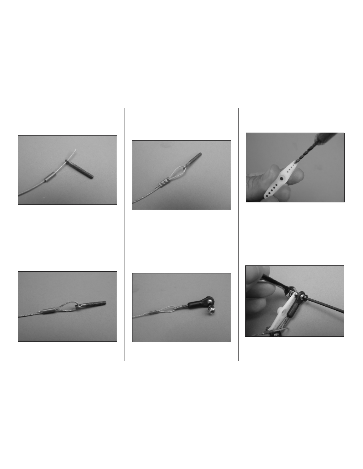
Step 15
Thread a 4-40 ball link assembly onto the rigging
coupler. Use pliers to grip the coupler while threading
the ball link on.
Step 16
Use a 3/32-inch drill bit in a pin vise to enlarge the
outer hole in each end of a JR heavy-duty servo arm.
Step 17
Use a 5/64-inch hex wrench and 1/4-inch open-end
wrench to install the ball link and cable assemblies
onto the servo arm.
12
Hangar 9 Taylorcraft 20cc Assembly Manual
Step 18
Feed the free end of each rudder pull-pull cable into
the guide tubes inside the fuselage. The tubes are
located in the first bulkhead behind the servo tray.
Step 19
Use your radio or JR Matchmaker to center the rudder
servo, and use a #1 Phillips screwdriver to secure the
arm to the servo.
Step 20
Invert the fuselage on the work table. Install a 4-40
hex nut and clevis on a rigging coupler so that about
three threads protrude from the barrel of the clevis.
Attach the clevis to the middle hole in the rudder horn.
Step 21
Slide a copper crimp onto the pull-pull cable.
Step 22
Insert the free end of the pull-pull cable through the
hole in the end of the rigging coupler.
Step 23
Insert the free end of the pull-pull cable through the
copper crimp.
13
Hangar 9 Taylorcraft 20cc Assembly Manual
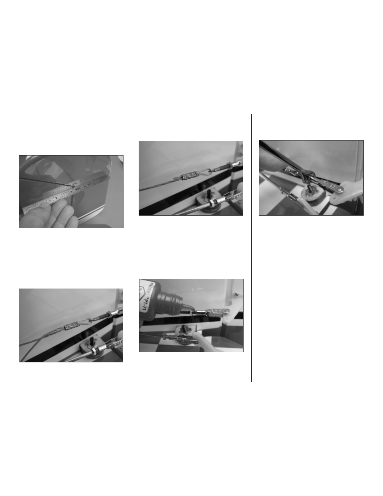
Step 24
Adjust the pull-pull cables in the rigging couplers to
center the rudder and remove slack from the cables.
Use a ruler to check the alignment of the rudder to the
fin while making the adjustments.
Step 25
Check that the rudder servo arm and rudder are
centered then use crimping pliers or sidecutters to
secure the copper crimp to the pull-pull cables.
Step 26
Use sidecutters to trim the excess cable protruding
from the crimp.
Step 26
Place a drop of threadlock on the threads of the
rigging coupler between the clevis and the hex nut.
Step 27
Use a 3/16-inch open-end wrench to tighten the hex
nut against the clevis.
Step 28
Repeat steps 26 and 27 to secure the hex nuts
against the elevator clevises.
14
Hangar 9 Taylorcraft 20cc Assembly Manual
Tailwheel Installation
Required Parts
Fuselage Tailwheel assembly
Tiller arm Springs
#4 washer (2)
#4 x 3/4-inch socket head cap screw
#2 x 5/8-inch self-tapping screws
Aluminum tab from tail brace parts bag
Required Tools
Pin vise 1/32-inch drill bit
Felt-tipped pen Thin CA
2.5mm hex wrench Needle nose pliers
3/32-in hex wrench #1 Phillips screwdriver
Step 1
Invert the fuselage on the work table. Place the tiller
arm on the bottom of the rudder with its edge aligned
with the forward edge of the rudder. Mark the
mounting holes with a felt-tipped pen.
Step 2
Use a 1/32-inch drill in a pin vise to drill the mounting
holes for the tiller arm screws.
Step 3
Place 3–4 drops of thin CA in each of the holes to
strengthen the wood around the holes. Do not use
accelerator as the CA needs to fully penetrate the wood.
Step 4
Use a #1 Phillips screwdriver to install the tiller arm
with two #2 x 5/8-inch self-tapping screws.
Step 5
Apply a 1–2 drops of thin CA to each of the tailwheel
mounting holes. Do not use accelerator as the CA
needs to fully penetrate the wood.
15
Hangar 9 Taylorcraft 20cc Assembly Manual
Step 6
Place the tailwheel assembly over the mounting holes
on the rear fuselage. Use a 3/32-in hex wrench to
install a #4 x 3/4-in socket head wood screw and #4
steel washer in the forward mounting hole.
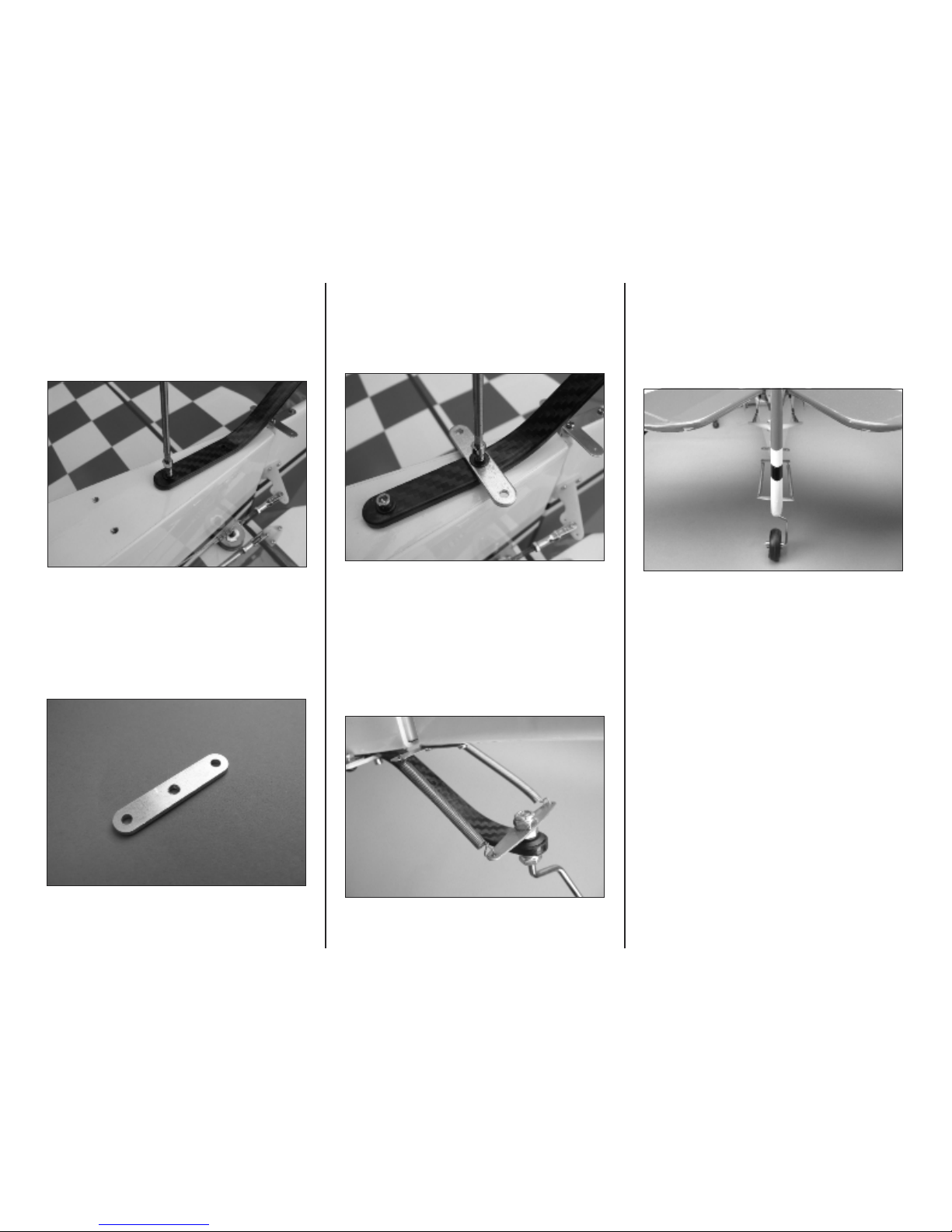
Step 7
Locate the aluminum mounting tab from the tail brace
parts bag.
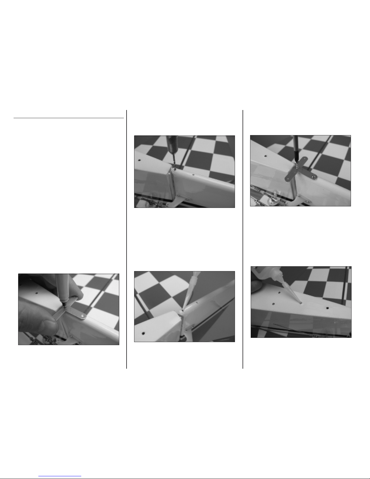
Step 8
Place the aluminum tab on the tailwheel assembly
over the rear hole. Use a 3/32-in hex wrench to install
the second mounting screw and washer.
Step 9
Use needle nose pliers to bend a loop in each end of
the tailwheel steering springs and attach them to each
end of the steering tiller on the rudder and tailwheel
assembly.
Step 10
The springs should be under slight tension when
installed. Form the springs to approximately equal
lengths and adjust as necessary to align the tailwheel
with the rudder.

17
Hangar 9 Taylorcraft 20cc Assembly Manual
Step 6
Locate the 10 1/4-inch lower rear stabilizer strut.
Install it on the lower surface of the stabilizer over the
screw inserted in Step 5 and thread on a 4-40 nylon
lock nut.
Step 7
Use a 5/64-inch hex wrench and 1/4-inch open-end
wrench to tighten the brass strap and rear strut to the
stabilizer.
Step 8
Attach the inboard end of the rear strut to the top of
the aluminum tab with a 4-40 x 1/4-inch button head
machine screw and 4-40 nylon locknut.
Step 9
Use a 5/64-inch hex wrench and 1/4-inch open-end
wrench to tighten the rear strut to the aluminum tab.
Step 10
Thread a 4-40 rod end onto the threaded section of
the upper brace wire and adjust it until the hole is
aligned with the hole in the brass tab.
Step 11
Place a small amount of threadlock on a 4-40 x 1/4inch button head machine screw and install it with a
5/64-inch hex wrench.

16
Hangar 9 Taylorcraft 20cc Assembly Manual
Tail Brace Installation
Parts Required
Fuselage Lower strut (4)
Brass tab (2) Upper brace wire (2)
4-40 rod end (2) 4-40 hex nut (2)
#4 washer (6) 4-40 nylon lock nut (6)
4-40 x 5/8-inch button head machine screw (5)
4-40 x 1/4-inch button head machine screw (4)
Tools Required
5/64-in hex wrench Threadlock
Needle nose pliers 1/4-inch open-end wrench
Step 1
Insert a #4 washer and 4-40 x 5/8-inch button head
machine screw through the mounting tab of the upper
wire brace and into the rear hole in the fin. Whether
the bolt head is on the left or right side is not critical.
Step 2
On the opposite side of the fin, place the other wire
brace over the protruding screw, then a #4 washer
and 4-40 nylon lock nut.
Step 3.
Use a 5/64-inch hex wrench and 1/4-inch open-end
wrench to tighten the upper brace wires against the
fin. Only a snug fit is necessary so as not to crush the
structure.
Step 4
Use a pair of needle nose pliers to form a bend in the
center of each of the brass tabs.
Step 5
Install the brass tab to the rear hole on the upper
surface of the stabilizer with a #4 washer and 4-40 x
5/8-in button head hex screw.
 Loading...