

Page 1
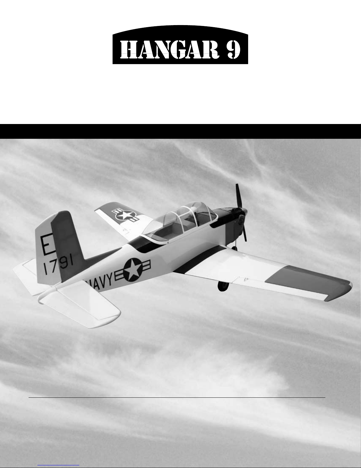
T-34 Mentor 40 ARF
®
Assembly mAnuAl
Specifications
Wingspan .................................. 57.75 in (1454mm)
Wing Area
Length ............................................ 45 in (1146mm)
........................... 555 sq in (35.8 sq dm)
Weight ................................. 6–7 lb (2.7 kg–3.2 kg)
Radio................................. 4-Channel w/5–7 servos
Engines ............ .40–.52 2-stroke, .56–.72 4-stroke
Page 2

Table of Contents
Contents of Kit . . . . . . . . . . . . . . . . . . . . . . . . . . . . . . . . . . . . . . . . . . . . . . . . . . . . . . . . . . . . . . . . . . . .3
UltraCote Covering Colors
Radio and Power Systems Requirements
Field Equipment Required
Optional Field Equipment
Required Tools and Adhesives
Other Items Needed (not included in the kit)
Limited Warranty Period
Limited Warranty & Limits of Liability
Safety Precautions
Questions, Assistance, and Repairs
Questions or Assistance
Inspection or Repairs
Warranty Inspection and Repairs
Non-Warranty Repairs
Safety, Precautions, and Warnings
Before Starting Assembly
Using the Manual
Section 1: Joining the Wing Halves
Section 2: Installing the Horizontal Stabilizer . . . . . . . . . . . . . . . . . . . . . . . . . . . . . . . . . . . . . . . . . . . .
Section 3: Installing the Vertical Stabilizer
Section 4: Installing the Ailerons
Section 5: Installing the Elevators
Section 6: Installing the Rudder
Section 7: Fixed Gear Installation
Section 8: Retract Installation
Section 9: Retract Linkage Installation
Section 10: Engine Installation
Section 11: Throttle Pushrod Installation
Section 12: Fuel Tank Installation
Section 13: Electric Motor Installation
Section 14: Radio Installation
Section 15: Linkage Installation
Section 16: Cowling Installation
Section 17: Canopy and Decal Installation
Recommended CG Location
Recommended Control Throws
Adjusting the Engine
Pre-Flight . . . . . . . . . . . . . . . . . . . . . . . . . . . . . . . . . . . . . . . . . . . . . . . . . . . . . . . . . . . . . . . . . . . . . . .57
Range Test Your Radio
2006 Official AMA National Model Aircraft Safety Code
. . . . . . . . . . . . . . . . . . . . . . . . . . . . . . . . . . . . . . . . . . . . . . . . . . . . . . . . . . . . . . . . .6
. . . . . . . . . . . . . . . . . . . . . . . . . . . . . . . . . . . . . . . . . . . . . . . . . . . . . . . . . . . . . . . . . .8
. . . . . . . . . . . . . . . . . . . . . . . . . . . . . . . . . . . . . . . . . . . . . . . . . . . . . . . . . . .4
. . . . . . . . . . . . . . . . . . . . . . . . . . . . . . . . . . . . . . . . . . . . . . . .4
. . . . . . . . . . . . . . . . . . . . . . . . . . . . . . . . . . . . . . . . . . . . . . . . . . . . . . . . . . . .4
. . . . . . . . . . . . . . . . . . . . . . . . . . . . . . . . . . . . . . . . . . . . . . . . . . . . . . . . . . . .4
. . . . . . . . . . . . . . . . . . . . . . . . . . . . . . . . . . . . . . . . . . . . . . . . . . . . . . . .5
. . . . . . . . . . . . . . . . . . . . . . . . . . . . . . . . . . . . . . . . . . . . . .5
. . . . . . . . . . . . . . . . . . . . . . . . . . . . . . . . . . . . . . . . . . . . . . . . . . . . . . . . . . . . .6
. . . . . . . . . . . . . . . . . . . . . . . . . . . . . . . . . . . . . . . . . . . . . . . . . .6
. . . . . . . . . . . . . . . . . . . . . . . . . . . . . . . . . . . . . . . . . . . . . . . . . . . .6
. . . . . . . . . . . . . . . . . . . . . . . . . . . . . . . . . . . . . . . . . . . . . . . . . . . . . . . . . . . . .6
. . . . . . . . . . . . . . . . . . . . . . . . . . . . . . . . . . . . . . . . . . . . . . . . . . . . . . . . . . . . . . .7
. . . . . . . . . . . . . . . . . . . . . . . . . . . . . . . . . . . . . . . . . . . . . . . . . . . . . . .7
. . . . . . . . . . . . . . . . . . . . . . . . . . . . . . . . . . . . . . . . . . . . . . . . . . . . . . . . . . . . . . .7
. . . . . . . . . . . . . . . . . . . . . . . . . . . . . . . . . . . . . . . . . . . . . . . . . . . . .8
. . . . . . . . . . . . . . . . . . . . . . . . . . . . . . . . . . . . . . . . . . . . . . . . . . . . . . . . . . . .8
. . . . . . . . . . . . . . . . . . . . . . . . . . . . . . . . . . . . . . . . . . . . . . . . . . . .9
11
. . . . . . . . . . . . . . . . . . . . . . . . . . . . . . . . . . . . . . . . . . . . . .14
. . . . . . . . . . . . . . . . . . . . . . . . . . . . . . . . . . . . . . . . . . . . . . . . . . . . .16
. . . . . . . . . . . . . . . . . . . . . . . . . . . . . . . . . . . . . . . . . . . . . . . . . . . . .18
. . . . . . . . . . . . . . . . . . . . . . . . . . . . . . . . . . . . . . . . . . . . . . . . . . . . . .20
. . . . . . . . . . . . . . . . . . . . . . . . . . . . . . . . . . . . . . . . . . . . . . . . . . . . .21
. . . . . . . . . . . . . . . . . . . . . . . . . . . . . . . . . . . . . . . . . . . . . . . . . . . . . . . .26
. . . . . . . . . . . . . . . . . . . . . . . . . . . . . . . . . . . . . . . . . . . . . . . . .31
. . . . . . . . . . . . . . . . . . . . . . . . . . . . . . . . . . . . . . . . . . . . . . . . . . . . . . .36
. . . . . . . . . . . . . . . . . . . . . . . . . . . . . . . . . . . . . . . . . . . . . . .38
. . . . . . . . . . . . . . . . . . . . . . . . . . . . . . . . . . . . . . . . . . . . . . . . . . . . .39
. . . . . . . . . . . . . . . . . . . . . . . . . . . . . . . . . . . . . . . . . . . . . . . . .40
. . . . . . . . . . . . . . . . . . . . . . . . . . . . . . . . . . . . . . . . . . . . . . . . . . . . . . . .43
. . . . . . . . . . . . . . . . . . . . . . . . . . . . . . . . . . . . . . . . . . . . . . . . . . . . . .47
. . . . . . . . . . . . . . . . . . . . . . . . . . . . . . . . . . . . . . . . . . . . . . . . . . . . . .53
. . . . . . . . . . . . . . . . . . . . . . . . . . . . . . . . . . . . . . . . . . . . . .55
. . . . . . . . . . . . . . . . . . . . . . . . . . . . . . . . . . . . . . . . . . . . . . . . . . . . . . . . .56
. . . . . . . . . . . . . . . . . . . . . . . . . . . . . . . . . . . . . . . . . . . . . . . . . . . . . . .56
. . . . . . . . . . . . . . . . . . . . . . . . . . . . . . . . . . . . . . . . . . . . . . . . . . . . . . . . . . . . . . .57
. . . . . . . . . . . . . . . . . . . . . . . . . . . . . . . . . . . . . . . . . . . . . . . . . . . . . . . . . . . . .57
. . . . . . . . . . . . . . . . . . . . . . . . . . . . . . . . . . . .58
2
Page 3
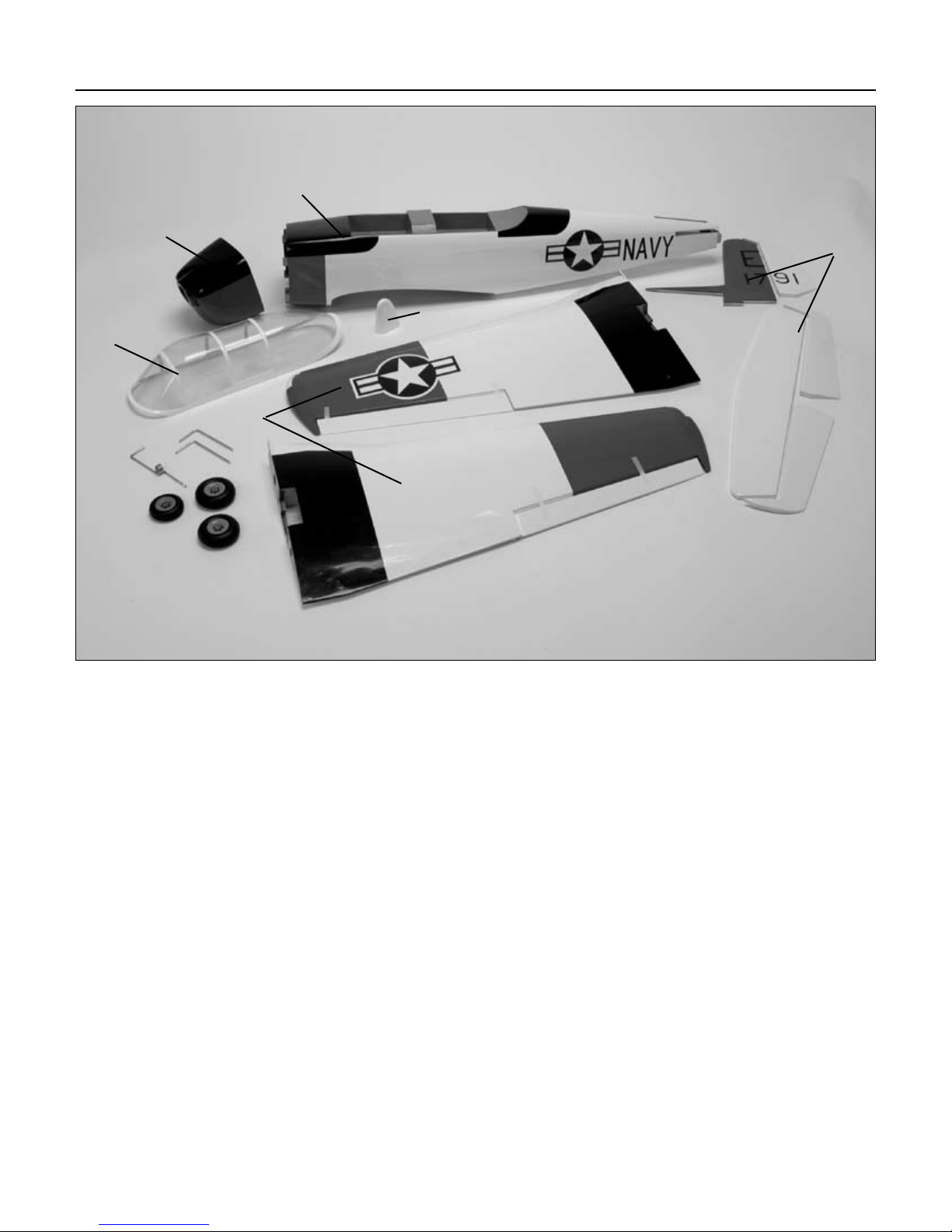
Contents of Kit
E
D
B
A
C
F
Replacement Parts
Large Parts
A. Fuselage HAN4326
B. Wing Set w/Joiner and Ailerons HAN4327
C. Tail Set HAN4328
D. Canopy HAN4330
E. Painted Cowl HAN4331
F. Tail Cone HAN4329
Items Not Shown
Fixed Landing Gear Set HAN2432
Decal Set HAN2433
3
Page 4
UltraCote® Covering Colors
• White HANU870 • True Red HANU866
• Black HANU874
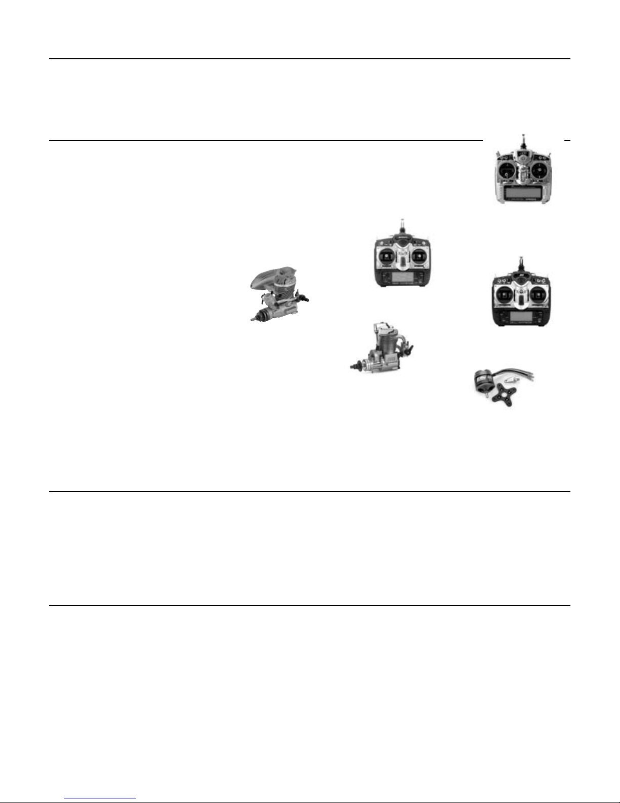
Radio and Power Systems Requirements
Radio Equipment
• 4-channel radio system (minimum)
(5 if using retracts)
• 5 standard servos (JRPS821, JSPST47BB recommended or equivalent)
(2 retract servos required if using retracts)
Recommended JR® or JR SPORT™ Systems
• XP9303
• XP7202
• XP6102
• XP662
• SX600
• S400
Recommended Power Systems
• .40–.52 2-stroke
• .56–.82 4-stroke
• Power 46 Brushless Outrunner
• EP Motor Mount (HAN4245) for electric motor installation
Evolution .46NT
EVOE0460
JR XP6102
Saito .82 AAC
SAIE082A
JR XP9303
JR XP7202
Power 46 Brushless
Outrunner Motor, 670KV
EFLM4046A
Field Equipment Required
• Propeller • Fuel
• Long Reach Glow Plug Wrench (HAN2510) • Metered Glow Driver w/Ni-Cd & Charger (HAN7101)
• 2-Cycle Sport Plug (HAN3001) • 2-Cycle Super Plug (HAN3006)
• 4-Cycle Super Plug (HAN3011) • Manual Fuel Pump (HAN118)
Optional Field Equipment
• 12V 7Ah Sealed Battery (HAN102) • PowerPro™ 12V Starter (HAN161)
4
Page 5

Required Tools and Adhesives
Tools
• Canopy Scissors • Drill
• Square • Flat blade screwdriver
• Foam: 1/2" (6mm) • Hobby knife
• Masking tape • Phillips screwdriver (large)
• Phillips screwdriver (small) • Pliers
• Ruler • Sandpaper
• Drill Bit: 1/16" (1.5mm), 3/32" (2.5mm), 1/8" (3mm), 7/32" (5.5mm), 1/4" (6mm)
Adhesives
• 6-minute epoxy • 30-minute epoxy
• Thin CA (cyanoacrylate) glue • Thick CA (cyanoacrylate) glue
• CA remover/debonder • Pacer Z-42 Threadlock
• Canopy glue (RC-56) • Masking tape (3M blue recommended)
Other Required Items
• Epoxy brushes • Felt-tipped pen or pencil
• File • Measuring device (e.g. ruler, tape measure)
• Mixing sticks for epoxy • Paper towels
• Petroleum jelly • Rubbing alcohol
• Sanding bar • Sandpaper (medium)
• String • T-pins
• Wax paper
Other Items Needed (not included in the kit)
• Propeller (consult engine instructions) • JRPS821, JSPST47BB or equivalent recommended
• 9" Servo Lead Extension (JRPA097) (2) • Mechanical Retracts, Tricycle (HAN157)
• JRPS791 Hi-Torque Low profile Retract Servo,
JSP RT-88 low profile retract servo, or equivalent
is recommended
5
Page 6

Limited Warranty Period
Horizon Hobby, Inc. guarantees this product to be free from defects in both material and workmanship at the date
of purchase.
Limited Warranty & Limits of Liability
Pursuant to this Limited Warranty, Horizon Hobby, Inc. will, at its option, (i) repair or (ii) replace, any product determined
by Horizon Hobby, Inc. to be defective. In the event of a defect, these are your exclusive remedies.
This warranty does not cover cosmetic damage or damage due to acts of God, accident, misuse, abuse, negligence,
commercial use, or modification of or to any part of the product. This warranty does not cover damage due to improper
installation, operation, maintenance, or attempted repair by anyone other than an authorized Horizon Hobby, Inc. service
center. This warranty is limited to the original purchaser and is not transferable. In no case shall Horizon Hobby’s
liability exceed the original cost of the purchased product and will not cover consequential, incidental or collateral
damage. Horizon Hobby, Inc. reserves the right to inspect any and all equipment involved in a warranty claim. Repair
or replacement decisions are at the sole discretion of Horizon Hobby, Inc. Further, Horizon Hobby reserves the right to
change or modify this warranty without notice.
REPAIR OR REPLACEMENT AS PROVIDED UNDER THIS WARRANTY IS THE EXCLUSIVE REMEDY OF THE CONSUMER.
HORIZON HOBBY, INC. SHALL NOT BE LIABLE FOR ANY INCIDENTAL OR CONSEQUENTIAL DAMAGES.
As Horizon Hobby, Inc. has no control over use, setup, final assembly, modification or misuse, no liability shall be
assumed nor accepted for any resulting damage or injury. By the act of use, setup or assembly, the user accepts all
resulting liability.
If you as the purchaser or user are not prepared to accept the liability associated with the use of this product, you are
advised to return this product immediately in new and unused condition to the place of purchase.
Safety Precautions
This is a sophisticated hobby product and not a toy. It must be operated with caution and common sense and requires
some basic mechanical ability. Failure to operate this product in a safe and responsible manner could result in injury or
damage to the product or other property. This product is not intended for use by children without direct adult supervision.
The product manual contains instructions for safety, operation and maintenance. It is essential to read and follow all the
instructions and warnings in the manual, prior to assembly, setup or use, in order to operate correctly and avoid damage
or injury.
Questions, Assistance, and Repairs
Your local hobby store and/or place of purchase cannot provide warranty support or repair. Once assembly, setup or use
of the product has been started, you must contact Horizon Hobby, Inc. directly. This will enable Horizon to better answer
your questions and service you in the event that you may need any assistance.
Questions or Assistance
For questions or assistance, please direct your email to productsupport@horizonhobby.com, or call 877.504.0233 toll
free to speak to a service technician.
6
Page 7

Inspection or Repairs
If your product needs to be inspected or repaired, please call for a Return Merchandise Authorization (RMA). Pack the
product securely using a shipping carton. Please note that original boxes may be included, but are not designed to
withstand the rigors of shipping without additional protection. Ship via a carrier that provides tracking and insurance for
lost or damaged parcels, as Horizon Hobby, Inc. is not responsible for merchandise until it arrives and is accepted at
our facility. Include your complete name, address, phone number where you can be reached during business days, RMA
number, and a brief summary of the problem. Be sure your name, address, and RMA number are clearly written on the
shipping carton.
Warranty Inspection and Repairs
To receive warranty service, you must include your original sales receipt verifying the proof-of-purchase date. Providing
warranty conditions have been met, your product will be repaired or replaced free of charge. Repair or replacement
decisions are at the sole discretion of Horizon Hobby.
Non-Warranty Repairs
Should your repair not be covered by warranty and the expense exceeds 50% of the retail purchase cost, you will be
provided with an estimate advising you of your options. You will be billed for any return freight for non-warranty repairs.
Please advise us of your preferred method of payment. Horizon Hobby accepts money orders and cashiers checks, as
well as Visa, MasterCard, American Express, and Discover cards. If you choose to pay by credit card, please include your
credit card number and expiration date. Any repair left unpaid or unclaimed after 90 days will be considered abandoned
and will be disposed of accordingly.
Electronics and engines requiring inspection or repair should be shipped to the following address (freight prepaid):
Horizon Service Center
4105 Fieldstone Road
Champaign, Illinois 61822
All other products requiring inspection or repair should be shipped to the following address (freight prepaid):
Horizon Product Support
4105 Fieldstone Road
Champaign, Illinois 61822
7
Page 8
Safety, Precautions, and Warnings
As the user of this product, you are solely responsible for operating it in manner that does not endanger yourself and
others or result in damage to the product or the property of others.
Carefully follow the directions and warnings for this and any optional support equipment (chargers, rechargeable battery
packs, etc.) that you use.
This model is controlled by a radio signal that is subject to interference from many sources outside your control. This
interference can cause momentary loss of control so it is necessary to always keep a safe distance in all directions around
your model, as this margin will help to avoid collisions or injury.
• Always operate your model in an open area away from cars, traffic, or people.
• Avoid operating your model in the street where injury or damage can occur.
• Never operate the model out into the street or populated areas for any reason.
• Never operate your model with low transmitter batteries.
• Carefully follow the directions and warnings for this and any optional support equipment (chargers, rechargeable
battery packs, etc.) that you use.
• Keep all chemicals, small parts and anything electrical out of the reach of children.
• Moisture causes damage to electronics. Avoid water exposure to all equipment not specifically designed and protected
for this purpose.
Before Starting Assembly
Before beginning the assembly of the Sopwith Camel, remove each part from its bag for inspection. Closely inspect the
fuselage, wing panels, rudder, and stabilizer for damage. If you find any damaged or missing parts, contact the place of
purchase.
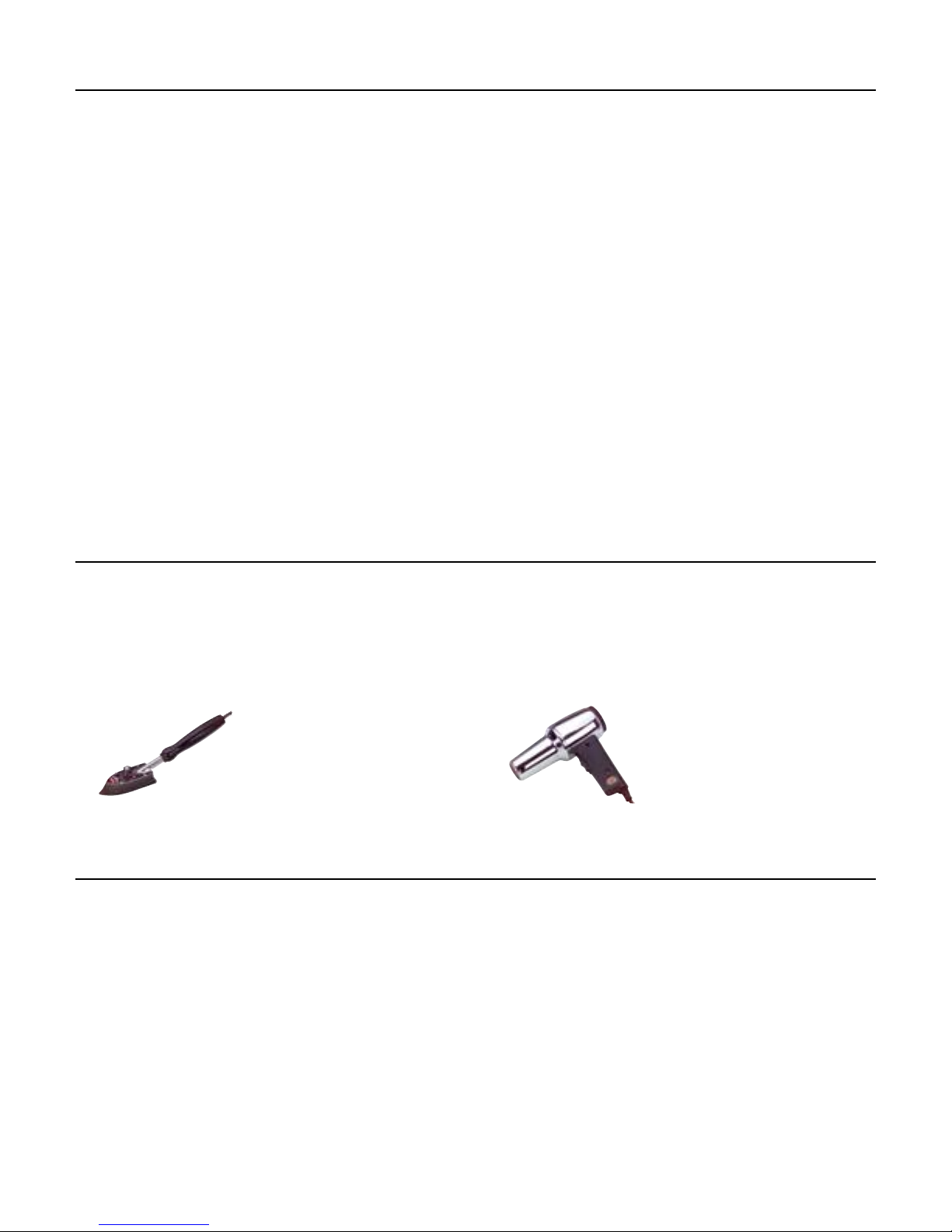
If you find any wrinkles in the covering, use a heat gun or sealing iron to remove them. Use caution while working around
areas where the colors overlap to prevent separating the colors.
HAN101 – Sealing Iron
HAN141 – Sealing Iron
Sock
HAN100 – Heat Gun
HAN150 – Covering Glove
Using the Manual
This manual is divided into sections to help make assembly easier to understand, and to provide breaks between each
major section. In addition, check boxes have been placed next to each step to keep track of each step completed. Steps
with a single box (
repeating, such as for a right or left wing panel, two servos, etc. Remember to take your time and follow the directions.
) are performed once, while steps with two boxes ( ) indicate that the step will require
8
Page 9
Section 1: Joining the Wing Halves
Required Parts
• Left and right wing panels
• Wing joiner (large & small)
• Wing dowels (2)
Required Tools and Adhesives
• Ruler • Masking tape
• 30-minute epoxy • Epoxy brush
• Mixing stick • Rubbing alcohol
• Paper towels
Step 1
Test the fit of the wing joiners into the right and left wing
panels. The joiners should slide into the panels with little
resistance. The larger joiner is located in the slot towards
the leading edge of the wing. Lightly sand the joiners if
they are a tight fit.
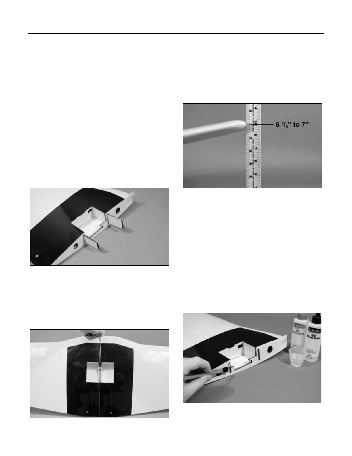
Step 3
With the wing panels together, check for correct dihedral.
Place the wing on a large flat surface with one panel
resting flat on the surface. The center of the opposite
wing tip should be 6
work surface. Once satisfied with the fit, separate the wing
panels and remove the wing joiner.
Note: Read through the remaining steps
of this section before mixing any epoxy.
7
/8" to 7" (175mm–178mm) from the
Step 2
Without using any glue, test fit the wing panels together
using the wing joiners. The panels must fit together
without any gaps top or bottom. If any gaps do exist, use
a sanding bar to lightly sand the root ribs of both panels
until the panels fit together perfectly.
Hint: It is extremely important to use
plenty of epoxy when joining the wing
panels. It will also be helpful to use
wax paper under the wing joint to avoid
gluing the wing to your work surface.
Step 4
Mix approximately 1 ounce of 30-minute epoxy. Using
an epoxy brush, apply a generous amount of epoxy to the
wing joiner cavities of one wing panel.
9
Page 10

Section 1: Joining the Wing Halves
Step 5
Completely coat one half of the each wing joiner with
epoxy. Be sure to apply epoxy to the top and bottom of the
joiner also. Insert the epoxy-coated side of the joiner into
the wing joiner cavity up to the mark on the joiner. If you
have used enough epoxy, it will ooze out of the cavity as
the joiner is installed. Remove any excess epoxy using a
paper towel and rubbing alcohol.
Step 6
Apply a generous amount of epoxy to the joiner cavity of
the opposite wing panel.
Step 7
Apply epoxy to the exposed portion of the wing joiner.
Step 9
Carefully slide the wing panels together. Apply enough
pressure to firmly seat the two wing panels together,
causing any excess epoxy to ooze out from between the
panels. Use rubbing alcohol and a paper towel to remove
the excess epoxy. Check to make sure there are no visible
gaps between the panels.
Step 10
Use masking tape to securely hold the wing panels
together. Place the wing assembly back onto the work
surface (covered with wax paper) and check the dihedral
angle. Allow the epoxy to fully cure before continuing to
the next section.
Step 8
Apply epoxy to root wing rib of both panels.
10
Page 11
Section 2: Installing the Horizontal Stabilizer
Required Parts
• Assembled wing • Fuselage
• Stabilizer
• 1/4-20 x 2" nylon bolts (2)
Required Tools and Adhesives
• Screwdriver (slotted) • Hobby knife
• Felt-tipped pen • Drill
• Drill bit: 1/4" (6mm) • Square
Step 1
Place the wing onto the fuselage and check the fit. Make
any adjustments necessary to the wing bolt holes and
attach the wing using the two 1/4-20 x 2" nylon bolts.
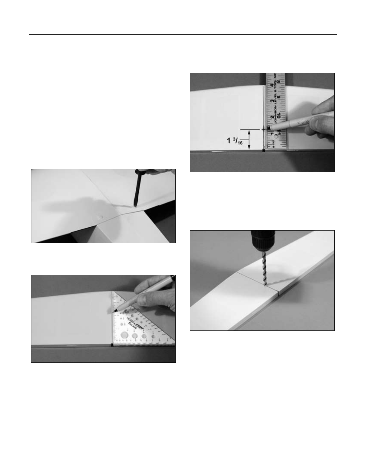
Step 3
Measure from the trailing edge of the stabilizer 1
(30mm). Use a felt-tipped pen to mark this location.
3
/16"
Step 4
Drill a hole at the location marked in the previous step
using a 1/4" (6mm) drill bit. It is highly suggested to use
a drill press to make sure the hole is perpendicular to the
stabilizer.
Step 2
Measure and mark a centerline on the stabilizer.
11
Page 12
A
A
A=A
A A
A=A
A A
A=A
Section 2: Installing the Horizontal Stabilizer
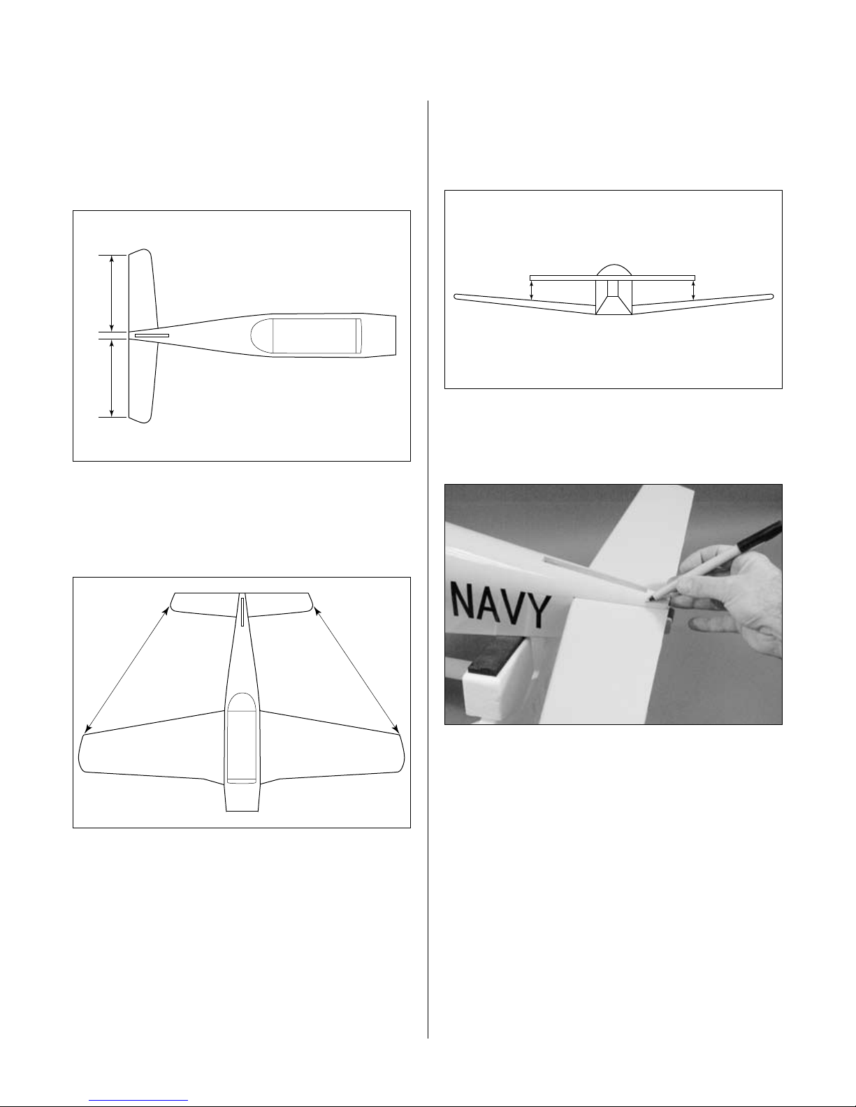
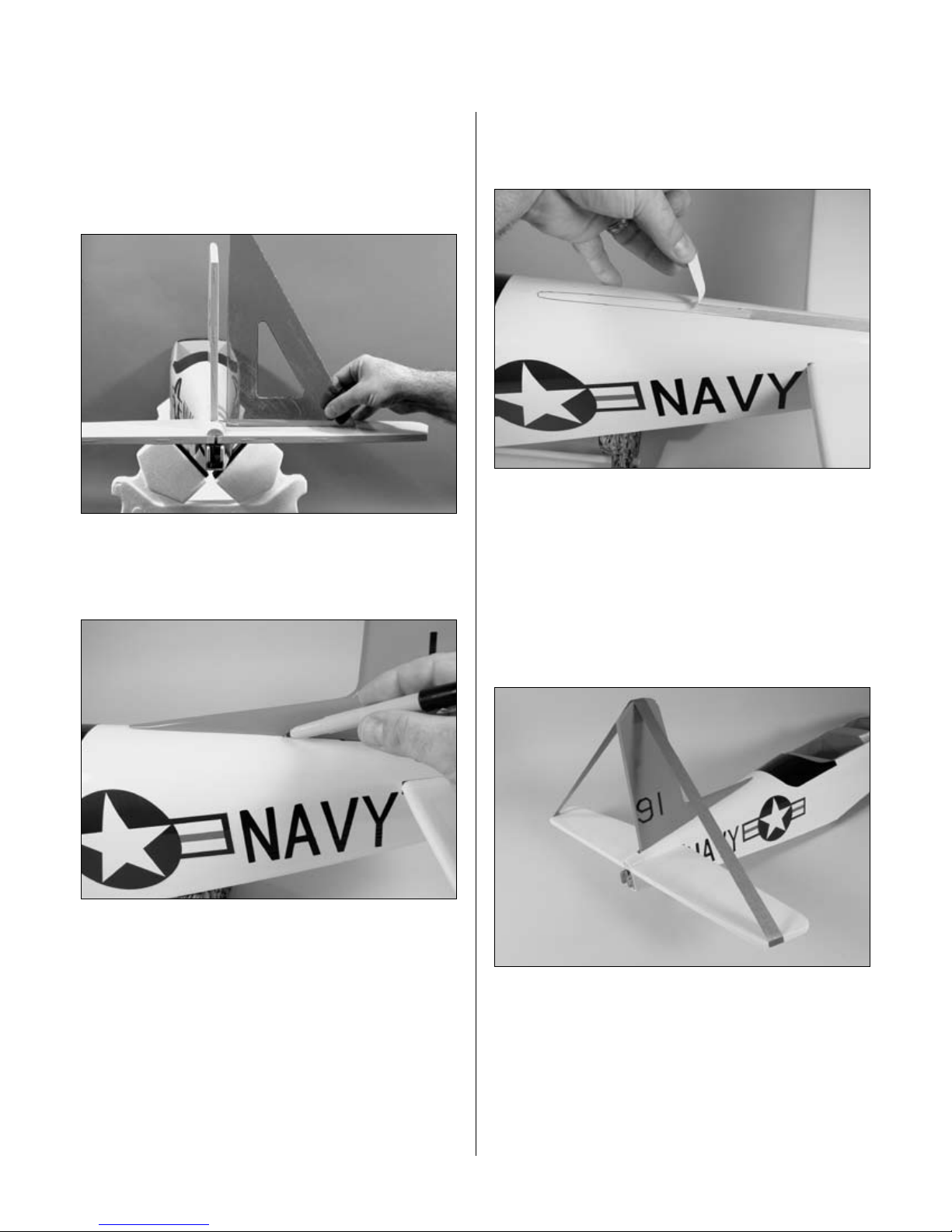
Step 5
Slide the stab into the fuselage. Center the stab in the
opening by measuring the distance from the fuselage to
each tip. The stab is aligned when both measurements are
identical.
Step 6
Step 7
Check to make sure the wing and stabilizer are parallel. If
they are not, lightly sand the opening in the fuselage for
the stab until the stab is parallel to the wing.
Step 8
Use a felt-tipped pen to trace the outline of the fuselage on
the stab.
Check the distance from each stab tip to each wing tip.
These measurements must be equal for the stab to be
aligned.
12
Page 13

Section 2: Installing the Horizontal Stabilizer
Step 9
Remove the stab and use a hobby knife with a brand new
blade to remove the covering 1/16" (1.5mm) inside the
lines just drawn. Use rubbing alcohol and a paper towel to
remove the lines once they are no longer needed.
Step 10
Mix 1/2 ounce (15ml) of 30-minute epoxy. Apply epoxy to
the top and bottom of the exposed wood of the stabilizer.
Apply epoxy to the corresponding surfaces of the slot in
the fuselage for the stabilizer. Slide the stabilizer into the
slot in the fuselage. Double-check the alignment to verify
it’s correct. Remove any excess epoxy using a paper towel
and rubbing alcohol.
Note: Use care not to cut into the underlying
wood and weaken the structure. Doing
so could cause the stab to fail in flight,
resulting in the loss of your airplane.
13
Page 14
Section 3: Installing the Vertical Stabilizer
Required Parts
• Fuselage assembly • Fin
• Rudder control rod
Required Tools and Adhesives
• 30-minute epoxy • Square
• Drill • Drill bit: 1/4" (6mm)
Step 1
Locate the rudder control rod. Insert the threaded end of
the control rod through the hole drilled in the stabilizer.
It may be necessary to slightly enlarge the hole in the
stabilizer and fuselage slightly to make the installation
easier.
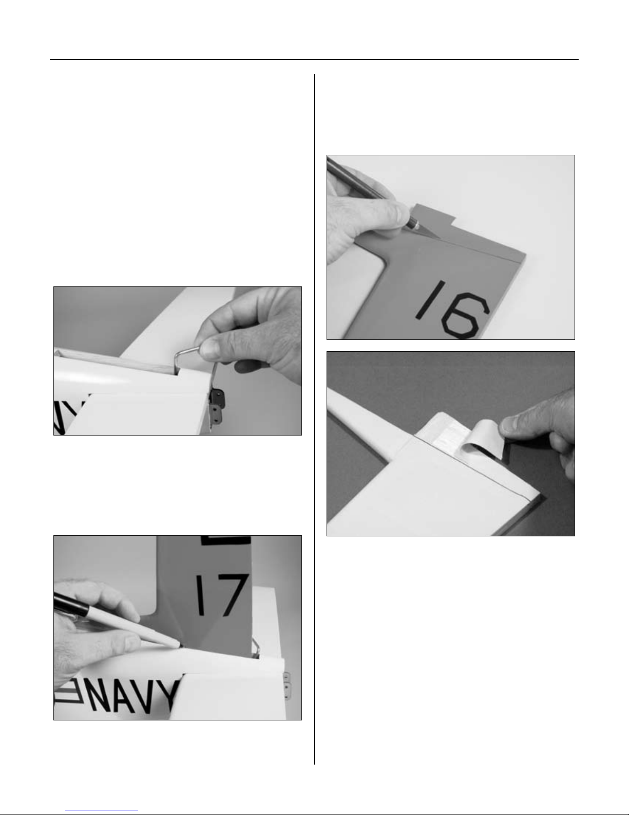
Step 3
Remove the fin and use a hobby knife with a brand new
blade to remove the covering 1/16" (1.5mm) below the
lines just drawn. Use rubbing alcohol and a paper towel to
remove the lines once they are no longer needed.
Step 2
Test fit the fin to the fuselage. Slide the fin as far forward
in the slot as possible to provide clearance for the rudder
control rod. Trace the outline of the fuselage onto the fin
using a felt-tipped pen.
Note: Use care not to cut into the underlying
wood and weaken the structure. Doing
so could cause the fin to fail in flight,
resulting in the loss of your airplane.
14
Page 15
Section 3: Installing the Vertical Stabilizer
Step 4
Check the alignment of the fin to the stabilizer using a
square. The fin must be 90 degrees to the stabilizer when
properly aligned. If not, carefully sand the bottom of the
fin to provide the clearance to align the fin.
Step 5
Trace the outline of the fin extension onto the fuselage
using a felt-tipped pen.
Step 6
Remove the covering 1/16" (1.5mm) inside the lines
drawn on the fuselage using a sharp hobby knife.
Step 7
Mix 1/2 (15ml) ounce of 30-minute epoxy. Apply the
epoxy to both the exposed wood on the fin and the slot
in the fuselage. Also apply epoxy to the exposed wood
on the top of the fuselage where the fin extension will be
glued. Use care not to get epoxy on the rudder control
rod. Insert the fin and use tape to hold the fin in position
until the epoxy fully cures.
Note: Check the alignment of the
fin periodically to make sure it isn’t
moving while the epoxy cures.
15
Page 16
Section 4: Installing the Ailerons
Required Parts
• Wing • Aileron (left and right)
• CA hinges (6)
Required Tools and Adhesives
• Thin CA • T-pins
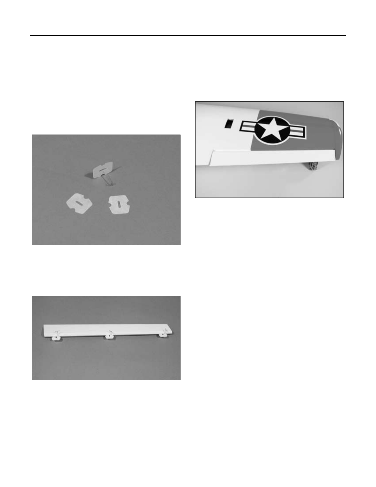
Step 1
Locate six of the CA hinges. Place a T-pin in the center of
three of the hinges.
Step 3
Slide the aileron and wing together. The gap between
the leading edge of the aileron and wing should be a
maximum of approximately 1/64" (.5mm). Check to make
sure the gap at both ends of the aileron are equal and it
can move without rubbing on the wing.
Note: Do not use CA accelerator during
the hinging process. The CA must be
allowed to soak into the hinge to provide
the best bond. Using accelerator will not
provide enough time for this process.
Step 2
Place the hinges in the precut slots in the aileron. The
T-pin will rest against the leading edge of the aileron when
installed correctly.
16
Page 17
Section 4: Installing the Ailerons
Step 4
Remove the T-pins and move the aileron to provide the
best access to the hinge. Apply thin CA to each hinge.
Make sure the hinge is fully saturated with CA. Use a
paper towel and CA remover/debonder to clean up any
excess CA from the wing and/or aileron.
Step 5
Firmly grasp the wing and aileron and gently pull on the
aileron to ensure the hinges are secure and cannot be
pulled apart. Use caution when gripping the wing and
aileron to avoid crushing the structure.
Step 6
Work the aileron up and down several times to work in the
hinges and check for proper movement.
Step 7
Repeat Steps 1 through 6 for the remaining aileron.
17
Page 18

Section 5: Installing the Elevators
Required Parts
• Fuselage assembly
• Elevator joiner wire • CA hinge (6)
• Elevator (left and right)
Required Tools and Adhesives
• Thin CA • T-pins
• 30-minute epoxy • Sandpaper (medium)
Step 1
Locate the elevator joiner wire. Use medium sandpaper to
roughen the portion of the wire that will be inserted in the
elevators.
Step 4
Place the hinges into the elevator halves.
Step 5
Slide the elevator and stab together. The horn on the
elevator joiner wire will face towards the bottom of the
fuselage.
Step 2
Insert the joiner into each of the elevator halves as shown.
Step 3
Locate six of the CA hinges. Place a T-pin in the center of
the hinges.
18
Page 19

Section 5: Installing the Elevators
Step 6
Check the movement of the elevators and make sure there
is plenty of clearance for the elevator control horn. It may
be necessary to trim the stabilizer and fuselage as shown
to allow for clearance of the horn.
Step 7
Step 8
Check to make sure both elevators move freely. They
should not rub against the stabilizer at the tips. Apply thin
CA to both sides of the hinge. Make sure to saturate the
hinge; don’t use accelerator.
Step 9
Once the CA and epoxy have fully cured, gently pull on
the elevator and stab to make sure the hinges are well
glued. Flex the elevators a few times to break in the
hinges.
Remove the elevators from the stabilizer. Mix 1/2 ounce
(15ml) of 30-minute epoxy and apply it to the groove and
hole in the elevator halves. Insert the elevator joiner wire.
Remove any excess epoxy using rubbing alcohol and a
paper towel.
Note: You can combine the previous step with
the following step if you like. This will hold
the elevator in position while the epoxy cures.
19
Page 20

Section 6: Installing the Rudder
Required Parts
• Fuselage assembly • Rudder
• CA hinge (3)
Required Tools and Adhesives
• Thin CA • T-pins
• 30-minute epoxy • Sandpaper (medium)
Step 1
Use medium sandpaper to roughen the portion of the
rudder control wire that will be inserted in the rudder.
Step 4
Check the movement of the rudder to make sure it clears
the fin and that the rudder control rod is not binding on
the fuselage.
Step 5
Remove the rudder from the fin. Mix 1/2 ounce (15ml)
of 30-minute epoxy and apply it to the groove and hole
in the rudder. Insert the rudder control rod. Remove any
excess epoxy using rubbing alcohol and a paper towel.
Step 2
Locate three CA hinges and place a T-pin in the center of
each hinge. Place the hinges into the rudder.
Step 3
Test fit the rudder to the fin and rudder control rod. The
control rod should face out through the opening in the
fuselage below the stabilizer. The gap between the rudder
and fin should be a maximum of approximately 1/64"
(.5mm).
Note: You can combine the previous step with
the following step if you like. This will hold
the rudder in position while the epoxy cures.
Step 6
Check to make sure the rudder moves freely. It should not
rub against the tip of the fin. Apply thin CA to both sides
of the hinge. Make sure to saturate the hinge and don’t
use accelerator.
Step 7
Once the CA and epoxy have fully cured, gently pull on
the fin and rudder to make sure the hinges are well glued.
Flex the rudder a few times to break in the hinges.
20
Page 21

Section 7: Fixed Gear Installation
Required Parts
1
• 2
/2" (63.5mm) main wheel (2)
• 2" (51mm) nose wheel
• Main gear wire (2) • Nose gear wire
• Main gear mount (2) • Nose gear mount
• 4mm wheel collar (6)
• 4mm brass wheel collar
• 3mm setscrew
• 3mm x 6mm machine screws (6)
• Steering arm • M3x8 machine screw
• 3mm x 12mm machine screw (2)
• 3mm x 12mm sheet metal screw (12)
• 3/8" x 5/8" x 6
(9.5mm x 16mm x 175mm) nose gear rail (2)
Required Tools and Adhesives
• Phillips screwdriver • File
• Drill
• Drill bit: 3/32" (2.5mm)
• 30-minute epoxy • Felt-tipped pen
• Hobby knife
• Threadlocking compound
Step 1
Locate the 3/8" x 5/8" x 6
nose gear rails. Slide the rails into the fuselage through
the openings in the firewall. The ends of the rails will rest
flush with second former. Mix 1 ounce of 30-minute epoxy
and glue the rails to the firewall and former 2.
7
/8"
7
/8" (9.5mm x 16mm x 175mm)
Step 2
Fuel-proof the firewall, nose gear rails, fuel tank area,
cowl mounting blocks and any other wood that may come
in contact with fuel of exhaust. Brush a light coating of
30-minute epoxy thinned with rubbing alcohol onto any
exposed wood. Doing so will extend the life of your model
by preventing damage to wood caused by contact with
fuel.
Step 3
Position the nose gear mount at the front edge of the rails.
Mark the location for the four screws using a felt-tipped
pen.
21
Page 22

Section 7: Fixed Gear Installation
Step 4
Drill the locations marked in the previous step using a
3/32" (2.5mm) drill bit.
Note: It may be necessary to lightly
sand the nose gear wire so it can move
freely in the nose gear mount.
Step 5
Attach the nose gear mount using four 3mm x 12mm
sheet metal screws.
Step 7
Slide the steering arm onto the nose gear wire, but do not
tighten the screw. Slide the nose gear wire into the nose
gear mount.
Step 8
Slide the 4mm brass wheel collar onto the nose gear wire.
Temporarily secure the collar to the nose gear wire using
a 3mm setscrew. Adjust the position of the wheel collar
until the nose gear is positioned 5
nose gear mount as shown.
1
/4" (134mm) from the
22
Page 23

Section 7: Fixed Gear Installation
Step 9
Slide the nose gear wire towards the bottom of the
fuselage. Slide the steering arm up against the nose
gear mount and secure the steering arm using a
3mm x 10mm machine screw.
Step 10
Install the nose wheel using two 4mm wheel collars and
two 3mm x 6mm machine screws. It is highly suggested
to apply threadlocking compound to the screws to prevent
them from loosening during flight.
Step 11
Use a sharp hobby knife to remove the covering from the
wing for the main gear. Use a covering iron to seal the
edges of the covering to the opening.
Step 12
Position the main gear mount in the wing. The location
for the screw will face towards the wing tip. Mark the
locations for the screws using a felt-tipped pen.
Note: It may be necessary to sand the
edges of the mount so it fits into position.
23
Page 24

Section 7: Fixed Gear Installation
Step 13
Drill the locations marked in the previous step using a
3/32" (2.5mm) drill bit. Work slowly as to avoid drilling
through the top of the wing.
Step 14
Attach the main gear mount using four 3mm x 12mm
sheet metal screws.
Step 15
Insert the main gear wire into the mount. Adjust the height
of the wire to 3" (76mm) as shown.
Note: It may be necessary to lightly
sand the main gear wire so it can be
inserted into the main gear mount.
Step 16
Rotate the main gear wire parallel to the centerline of
the wing. The goal is to have both main wheels pointing
straight forward when installed.
Hint: You can also use the mounting
screws as a reference.
24
Page 25

Step 19
Install the main gear wire and secure its location using
an 3mm x 12mm machine screw. Remember to check the
height of the gear as described in Step 15.
Section 7: Fixed Gear Installation
Step 20
Install the main wheel using two 4mm wheel collars and
two 3mm x 6mm machine screws. It is highly suggested
to apply threadlocking compound to the screws to prevent
them from loosening during flight.
Step 21
Repeat Steps 11 though 20 for the remaining main gear.
25
Page 26

Section 8: Retract Installation
Required Parts
• 2 1/2" (63.5mm) main wheel (2)
• 2" (51mm) nose wheel
• 4mm wheel collar (6)
• 3mm x 6mm machine screws (6)
• 3mm x 12mm sheet metal screw (12)
• 3/8" x 5/8" x 6
(9.5mm x 16mm x 175mm) nose gear rail (2)
Required Tools and Adhesives
• Drill
• Drill bit: 3/32" (2.5mm) , 1/4" (6mm)
• 30-minute epoxy • Felt-tipped pen
• Hobby knife • File
• Phillips screwdriver
• Threadlocking compound
• Rotary tool and cut-off wheel
Step 1
Locate the 3/8" x 5/8" x 6
nose gear rails. Slide the rails into the fuselage through
the openings in the firewall. The ends of the rails will rest
flush with second former. Once satisfied with the fit, mix 1
ounce of 30-minute epoxy and glue the rails to the firewall
and former 2.
7
/8"
7
/8" (9.5mm x 16mm x 175mm)
Step 2
Fuel-proof the firewall, nose gear rails, fuel tank area,
cowl mounting blocks and any other wood that may come
in contact with fuel of exhaust. Brush a light coating of
30-minute epoxy thinned with rubbing alcohol onto any
exposed wood. Doing so will extend the life of your model
by preventing damage to wood caused by fuel contact.
Step 3
Use a sharp hobby knife to remove the covering from the
fuselage for the nose gear. Use a covering iron to seal the
edge of the covering into the opening. See photo in Step 1
for details.
26
Step 4
Position the nose gear at the front edge of the
rails. Mark the location for the four screws using
a felt-tipped pen.
Page 27

Section 8: Retract Installation
Step 5
Drill the locations marked in the previous step using a
3/32" (2.5mm) drill bit.
Step 6
Mark the location on the firewall for the retract actuator
lever.
Step 8
Attach the nose gear using four 3mm x 12mm sheet metal
screws.
Step 9
Slide the axle supplied with the retracts onto the nose
gear wire. Temporarily secure the axle using the supplied
screws. Adjust the position of the axle until the nose gear
is positioned 5
shown. Tighten the screw to secure the axle to the nose
gear wire. Use a rotary tool and cut-off wheel to remove
the excess nose gear wire.
1
/4" (134mm) from the nose gear mount as
Step 7
Drill the location marked in the previous step using a 1/4"
(6mm) drill bit.
27
Page 28

Section 8: Retract Installation
Step 10
Install the nose wheel using two 4mm wheel collars and
two 3mm x 6mm machine screws. Apply threadlocking
compound to the screws to prevent them from loosening
during flight.
Step 11
Use a sharp hobby knife to remove the covering from the
wing for the main gear. Use a covering iron to seal the
edge of the covering into the opening.
Step 12
Position the main gear retract in the wing. The coil in the
wire will face towards the trailing edge of the wing. Mark
the locations for the mounting screws using a felt-tipped
pen.
Note: It may be necessary to sand the
edges of the mount so it fits into position.
Step 13
Drill the locations marked in the previous step using a
3/32" (2.5mm) drill bit. Work slowly to avoid drilling
through the top of the wing.
28
Page 29

Section 8: Retract Installation
Step 14
Attach the main gear mount using four 3mm x 12mm
sheet metal screws.
Step 15
Slide the axle supplied with the retracts onto the
main gear wire. Temporarily secure the axle using
the screw supplied with the retracts. Adjust the position
of the axle so it is 3" (76mm) from the face of the retract
mount.
Step 16
Rotate the axle parallel to the centerline of the wing. The
goal is to have both main wheels pointing straight forward
when installed.
Hint: You can also use the mounting
screws as a reference.
Step 17
Temporarily tighten the axle screw. This will leave a mark
on the wire for use in the next step.
Step 18
Remove the screw and axle. Make a flat spot on the wire
using a file at the location the screw contacted the wire.
This will prevent the axle from rotating on those less-thanperfect landings.
29
Page 30

Section 8: Retract Installation
Step 19
Install the axle and secure its location using the screw
supplied with the retracts. Remember to check the height
of the gear as described in Step 14. Remove the excess
wire that extends past the axle using a rotary tool and cutoff wheel.
Step 20
Install the main wheel using two 4mm wheel collars and
two 3mm x 6mm machine screws. Apply threadlocking
compound to the screws to prevent them from loosening
during flight.
Step 21
Repeat Steps 11 though 20 for the remaining
main gear.
30
Page 31

Section 9: Retract Linkage Installation
Required Parts
• Large quick connector (3) • Metal clevis (3)
• Clevis retainer (3) • 4-40 x 1/4" screw (3)
• 4-40 x 7" threaded rod (2) • 4-40 x 9
• Wing retract servo tray
• Fuselage retract servo tray
• Quick connector retainer (3)
Required Tools and Adhesives
• 6-minute epoxy • 3/32" hex wrench
• Drill • Thick CA
• Drill bit: 1/16" (1.5mm), 3/32" (2.5mm), 1/4" (6mm)
• Retract Servo (JRPS703)
• Retract Servo (JRPS513)
1
/4" rod
Step 1
Locate the wing retract servo tray. Use 6-minute epoxy to
glue the servo tray into position. The wide edge of the tray
will be positioned towards the leading edge of the wing.
Step 2
Install a low-profile retract servo in the wing retract servo
tray using the hardware provided with the servo. Prevent
splitting the servo tray by drilling 1/16” (1.5mm) holes for
the servo mounting screws.
Step 3
Slide a clevis retainer onto a clevis. Attach the clevis to a
4-40 x 7" threaded pushrod.
31
Page 32

Section 9: Retract Linkage Installation
Step 4
Install the linkage into the wing. Attach the clevis to the
retract actuator.
Note: Make a bend in the pushrod so the
pushrod will be positioned as close to the top
of the wing sheeting as possible to provide
clearance for the wheel when retracted.
Step 6
Use a 3/32" (2.5mm) drill bit to drill the appropriate holes
in the arm.
Step 7
Attach a large quick connector (not included) to the servo
arm using a quick connector retainer.
Step 5
Select a servo arm from those included with your servo
that has a distance of approximately 7/8" (22mm) between
equally spaced holes as shown.
32
Page 33

Section 9: Retract Linkage Installation
Step 8
Connect the retract servo to your radio system
and electronically move the servo to the retracted position.
Slide the retract control wire through the easy connector
as shown and secure the servo arm to the retract servo.
Step 9
With the retract servo in the retracted position, push the
retract linkage to manually retract the landing gear. Install
a 4-40 x 1/4" screw into the easy connector and tighten it
to secure the retract linkage.
Step 10
Repeat Steps 3 through 9 for the remaining main
gear retract.
Step 11
Slide a clevis retainer onto a clevis. Attach the clevis to a
4-40 x 9
1
/4" threaded pushrod.
Step 12
Drill a 1/4" (6mm) hole in former 2 centered between the
nose gear rails. The center of the hole will be 3/4" (19mm)
below the edge of the former as shown.
33
Page 34

Section 9: Retract Linkage Installation
Step 13
Slide the pushrod through the holes in the firewall and
former 2. Connect the clevis to the retract actuating lever.
Step 14
Apply a bead of thick CA to the corners of the fuselage
retract servo tray.
Step 15
Position the servo tray so the edge is in alignment with
the center opening of the servo tray. Use 6-minute epoxy
to glue the tray into position.
Step 16
Install a retract servo in the servo tray using the hardware
provided with the servo. Prevent splitting the servo tray
by drilling 1/16" (1.5mm) holes for the servo mounting
screws.
34
Page 35

Section 9: Retract Linkage Installation
Step 17
Select a servo arm from those included with your servo
that has a distance of 1/2" (13mm) from the center of
the arm. Use a 3/32" (2.5mm) drill bit to drill the
appropriate holes in the arm. Attach a large quick
connector (not included) to the servo arm using a
quick connector retainer.
Step 18
Connect the retract servo to your radio system and
electronically move the servo to the retracted position.
Slide the retract control wire through the easy connector
as shown and secure the servo wheel to the retract servo.
With the retract servo in the retracted position, push the
retract linkage to manually retract the landing gear. Install
a 4-40 x 1/4" screw into the easy connector and tighten it
to secure the retract linkage.
Step 19
Cycle the retract system several times to make sure there
is no binding. Also check to verify the gear locks in both
the extended and retracted positions. Make any necessary
adjustments to be sure the retracts are working and
locking correctly.
35
Page 36

Section 10: Engine Installation
Required Parts
• Engine mount (2) • 6-32 blind nut (4)
• 6-32 x 1" machine screw (4)
• #6 x 5/8" sheet metal screw (4)
Required Tools and Adhesives
• Drill
• Drill bit: 3/32" (2.5mm) , 7/32" 5.5mm)
• Clamps • Felt-tipped pen
Step 1
Position the engine on the engine mounts. Measure the
distance from the work surface to the drive washer. Adjust
the mounts so the distance is 4
to hold the mounts to the engine.
5
/8" (118mm). Use clamps
Step 3
Use a 3/32" (2.5mm) drill bit to mark the locations for the
engine mounting bolts.
Step 4
Remove the engine and drill the locations marked in the
previous step using a 3/32" (2.5mm) drill bit.
Step 2
Use a square to make sure the engine is perpendicular to
the work surface.
36
Note: Use a drill press for the best
results. This makes holes perfectly
perpendicular (square) to the mount.
Page 37

Step 6
Attach the engine using four #6 x 5/8" socket head sheet
metal screws.
Hint: Apply bar soap to the threads
of the screws to make them thread
more easily into the mount.
Section 10: Engine Installation
Step 8
Drill the locations marked in the previous step using a
7/32" (5.5mm) drill.
Step 7
Position the engine on the firewall so the tick marks on
the mount align with the vertical centerline. Position the
engine horizontally so it is centered on the horizontal
centerline. Mark the location of the mounting holes for the
engine mount onto the firewall.
Step 9
Mount the engine to the firewall by installing the 6-32
blind nuts into the backside of the firewall and securing
the mount with the 6-32 x 1" machine screws.
37
Page 38

Section 11: Throttle Pushrod Installation
Required Parts
• Clevis retainer • Clevis
• 2-56 x 14
5
/8" pushrod
Required Tools and Adhesives
• Drill
• Drill bit: 3/32" (2.5mm)
• Pliers
Step 1
Drill a 3/32" (2.5mm) hole in the firewall and former 2 as
shown. The position is not critical as long as they align
parallel to the nose gear rail.
Step 3
Slide the pushrod into the fuselage from the front. Make
any necessary bends in the pushrod wire to attach it to the
throttle arm of the engine. Make sure it will not interfere
with the muffler when installed.
Step 2
Slide a clevis retainer onto a clevis. Attach the clevis to
the 2-56 x 14
38
5
/8" threaded pushrod.
Page 39

Section 12: Fuel Tank Installation
Required Parts
• Fuselage assembly • Fuel tank assembly
• Fuel tubing (red and green)
Required Tools and Adhesives
• Foam: 1/2" (13mm) • Masking tape
When installing the fuel tank, make sure to
have a piece of foam at any point that contacts
any structure inside the fuselage. Without
the foam, vibrations will be transmitted
to the fuel tank, which could cause the
fuel to foam. In turn, you will not get the
optimum performance from your engine.
Step 1
Wrap the fuel tank in 1/2" (13mm) foam as shown.
Note: Make sure that any support
braces installed will not interfere with the
installation of the wing or linkages.
Step 3
Remove the covering from the fuse bottom to expose the
opening for the exhaust if using a 2-stroke engine. Install
the muffler. There should be an even amount of clearance
between the muffler and firewall. Sand the opening in the
firewall if this is not the case. Install a muffler extension to
route the exhaust out of the fuselage.
Note: Connect the red tube to the vent
and the green tube to the pickup.
Step 2
Install the fuel tank into the fuselage. Make any necessary
supports to keep the tank from moving during flight.
Step 4
Make the proper connections to the engine, using the
engine manufacturer’s instructions.
39
Page 40

Section 13: Electric Motor Installation
Required Parts
• Fuselage
• 8-32 x 1/2" screw (4) • 8-32 blind nut (4)
Required Tools and Adhesives
• Phillips screwdriver • Threadlock
• Drill • Solder
• Male Deans connector (3) • Soldering iron
• Drill bit: 9/64" (3.5mm), 7/32" (5.5mm)
• Female Deans connector w/wire
• EP Motor Mount (HAN4245)
• 4200mAh 2S2P 7.4V Li-Po (2)
Note: Although the T-34 Mentor was not
designed as an electric aircraft, it can be
easily converted to electric by using the
Hangar 9
®
Electric Mount and a little ingenuity.
Step 1
Position the electric motor mount so the outer edge of
the mount is aligned with the outer edge of the plywood
spacer on the firewall. Use a felt-tipped pen to mark the
locations for the mounting holes on the electric mount.
Step 2
Drill the locations marked in the previous step using a
7/32" (5.5mm) drill.
Step 3
Attach the motor mount to the firewall using the four
8-32 x 1/2" machine screws, four 8-32 washers and the
four 8-32 blind nuts that were included in the kit..
Apply threadlock on the screws to prevent them from
vibrating loose.
40
Page 41

Section 13: Electric Motor Installation
Step 4
Depending on your motor selection, you’ll need to have
the motor output shaft protruding through the non-rotating
end of the motor. Follow the instructions included with
your motor if necessary to relocate the output shaft.
Step 5
Mount the motor to the motor mount front using hardware
included with the motor.
Step 6
Attach the motor mount front to the motor mount sides
using four 8-32 x 1/2" socket head screws, four #8
washers and four 8-32 lock nuts. With the propeller
adapter installed, position the motor mount so the face of
the adapter is 4
5
/8" (118mm) from the firewall.
Step 7
Build a wiring harness for the batteries using a female
connector and two male connectors. Follow the wiring in
the photo so the motor sees the voltage increase of the
two batteries.
41
Page 42

Section 13: Electric Motor Installation
Step 8
Solder the appropriate connectors onto the speed control.
Step 9
Remove the covering from both sides of the fuselage
as shown to allow for cooling air across the motor
and batteries.
Step 10
Create a battery tray or other method for securing the
batteries inside the fuselage. Make sure that if you are
installing retracts, the batteries won't interfere with the
retract servo and linkage.
Step 11
Attach the speed control inside the fuselage where it will
have sufficient air flow. Plug the motor into the speed
control. Plug the speed control into the receiver. Mount
the speed control inside the fuselage so it will not interfere
with the installation and removal of the batteries.
Step 12
Turn on the radio system. Plug the wiring harness
assembled in Step 4 into the batteries and speed control.
Use the throttle on the transmitter to check that everything
is working correctly. Check that the motor is rotating
counterclockwise. If not, follow the directions included
with the speed control to correct the situation.
Step 13
Once the motor is working and rotating in the correct
direction, unplug the wiring harness for safety.
42
Page 43

Section 14: Radio Installation
Required Parts
• Fuselage assembly • Wing assembly
• Servo w/hardware (5)
Required Tools and Adhesives
• Drill
• Drill bit: 1/16" (1.5mm), 3/32" (2.5mm)
• Phillips screwdriver (small)
• 9" Servo Extension (JRPA097) (2)
Step 1
Install the recommended servo hardware (grommets and
eyelets) supplied with your radio system onto five servos
(elevator, rudder, throttle and 2 ailerons).
Step 2
Temporarily install the rudder, elevator, and throttle servos.
Mark the locations for the servos screws using a felttipped pen.
Step 3
Remove the servo and drill the holes for the servo
mounting screws using a 1/16" (1.5mm) drill bit.
Hint: Place a drop of thin CA onto
each screw hole to harden the wood
around the hole. Allow the CA to fully
cure before installing the servos.
Step 4
Secure the servos using the screws provided with the
servos.
43
Page 44

Section 14: Radio Installation
Step 5
Mount the radio switch to the side of the fuselage.
Step 6
Wrap the receiver and receiver battery in protective
foam to prevent damage that may be caused by engine
vibration.
Step 8
Temporarily mount the receiver and battery into the
fuselage. It may be necessary to relocate the battery
forward or aft to balance the model as described in the
section “Control Throws and Center of Gravity.”
Step 9
Route the antenna through the bottom of the fuselage and
secure it to a location at the tail with rubber bands.
Step 7
Connect any necessary extensions and Y-harnesses
necessary to connect the retract and aileron servos.
Connect the elevator, rudder and throttle servo leads
to the receiver.
44
Page 45

Section 14: Radio Installation
Step 11
Temporarily install the aileron servo and mark the
locations for the servos screws using a felt-tipped pen.
Step 12
Remove the servos and drill holes for the servo mounting
screws using a 1/16" (1.5mm) drill bit.
Step 13
Connect a 9" Servo Extension (JRPA097) to the servo
lead. Secure the connectors by tying them in a knot
using dental floss (as shown) or by using a commercially
available connector clamp to prevent the servo leads from
becoming disconnected.
Step 14
Use a piece of string with a small weight (such as a wheel
collar) attached as a device to pull the servo lead through
the wing. Lower the weight through the servo opening,
allowing it to pass through the ribs and out of the hole in
the center of the wing.
45
Page 46

Section 14: Radio Installation
Step 15
Tie the string onto the servo extension. Gently pull the
extension through the wing using the string. Untie the
string when the servo lead has been pulled through. Use
tape to secure the servo lead to the wing to prevent it from
falling back into the wing panel.
Step 16
Secure the aileron servo using the screws provided with
the servo.
Step 17
Repeat Steps 10 through 15 for the remaining aileron
servo.
46
Page 47

Section 15: Linkage Installation
Required Parts
• Fuselage assembly • Wing assembly
1
• 18
/8" pushrod wire • 4 3/4" pushrod wire
• Nylon clevis (5) • Clevis retainer (5)
• Nylon wire keeper (5) • Rudder control horn
• Nylon control horn (2) • 2-56 x 3/4" screw (6)
• Quick connector
• Quick connector backplate
• 3mm x 6mm machine screw
1
• 23
/4" assembled pushrod
1
• 24
/2" assembled pushrod
Required Tools and Adhesives
• Drill
• Drill bit: 1/16" (1.5mm), 3/32" (2.5mm)
• Phillips screwdriver (small)
Step 1
Slide a clevis retainer onto a nylon clevis. Thread a clevis
onto the 24
turns.
1
/2" assembled pushrod a minimum of 10
Step 2
Slide the pushrod assembly into the fuselage from the
rear. Make sure the pushrod goes through the center hole
in the fuselage former. Attach the clevis to the center hole
in the elevator control wire.
Step 3
Center the elevator servo electronically using the radio
system. Install a servo arm onto the elevator servo. Mark
the pushrod where it crosses the holes in the servo arm.
47
Page 48

Section 15: Linkage Installation
Step 4
Bend the wire 90 degrees at the mark made in the
previous step.
Step 5
Slide the wire through the outer hole in the elevator servo
arm. Secure the wire using a nylon wire keeper.
Step 6
Thread the rudder control horn onto the rudder control
wire until the outer edge of the horn is flush with the end
of the wire.
Step 7
Slide a clevis retainer onto a nylon clevis. Thread
a clevis onto the 23
1
/4" assembled pushrod a minimum
of 10 turns.
Step 8
Slide the pushrod assembly into the fuselage from the
radio compartment. Make sure the pushrod goes through
the outer hole in the fuselage former. Attach the clevis to
the rudder control horn. Make adjustments to the pushrod
and fuselage to provide free movement of the rudder and
pushrod.
48
Page 49

Section 15: Linkage Installation
Step 9
Center the rudder servo electronically using the radio
system. Install a servo arm onto the rudder servo. Mark
the pushrod where it crosses the holes in the servo arm.
Step 10
Bend the wire 90 degrees at the mark made in the
previous step.
Step 12
Drill a 3/32" (2.5mm) hole in the firewall and former 2 as
shown. The position is not critical as long as they align
parallel to the nose gear rail.
Step 11
Slide the wire through the center hole in the rudder servo
arm. Secure the wire using a nylon wire keeper.
Step 13
Slide a clevis retainer onto a clevis. Attach the clevis to
the 2-56 x 18
1
/8" threaded pushrod.
49
Page 50

Section 15: Linkage Installation
Step 14
Slide the pushrod into the fuselage from the front. Make
any necessary bends in the pushrod wire to attach it to the
steering arm. Make sure it will not interfere with the nose
gear rail when it is installed.
Note: Steps 12 through 14 show the retract,
but the procedure is identical for fixed gear.
Step 16
Use a 3/32" (2.5mm) drill bit to drill out the holes in a
servo arm. Attach an easy connector to the arm using a
connector back plate.
Step 17
Center the throttle stick and trim with both the receiver
and transmitter on. Slide the easy connector onto the
throttle pushrod. Install the throttle servo arm in the
neutral position as shown.
Step 15
Mark the pushrod where it crosses the holes in the servo
arm. Bend the wire 90 degrees at the mark made in the
previous step. Slide the wire through the center hole in
the rudder servo arm. Secure the wire using a nylon wire
keeper.
50
Page 51

Section 15: Linkage Installation
Step 18
Move the throttle stick and trim to low. Check to make
sure the carburetor will move to the closed position when
operating the servo. Install an 3mm x 8mm screw to
secure the easy connector to the throttle pushrod. Check
the movement of the throttle to verify there is no binding
at either low or high throttle, and that the carburetor can
move through the full range of movement. If there is any
binding, make the necessary adjustment to eliminate
any binding. Install the throttle servo arm screw when
complete.
Step 20
Drill three 3/32" (2mm) holes through the ailerons at the
locations marked in the previous step.
Step 21
Place 2–3 drops of thin CA into the hole to harden the
wood. This will eliminate the potential of the screw
crushing of the wood. Repeat this for each of the three
holes.
Step 19
Position the control horn on the aileron so the horn aligns
with the hinge line of the aileron. Mark the position for the
mounting holes using a felt-tipped pen.
51
Page 52

Section 15: Linkage Installation
Step 22
Attach the control horn using three 2-56 x 3/4" screws
and the control horn backplate.
Step 23
Center the aileron servo electronically using the radio
system. Install a servo arm onto the aileron servo. Attach
the pushrod with clevis to the control horn. Physically
place the aileron control surface in neutral. Mark the
pushrod where it crosses the holes in the servo arm.
Step 24
Bend the wire 90 degrees at the mark made in the
previous step. Cut the wire 1/2" (13mm) above the bend.
Drill 1 3/32" (2mm) hole in the servo arm then slide the
wire through the hole in the aileron servo arm. Secure the
wire using a nylon wire keeper.
52
Note: Remove the excess arms from
the servo horn using side cutters.
Step 25
Repeat Steps 19 through 24 for the other aileron servo.
Page 53

Section 16: Cowling Installation
Required Parts
• Fuselage assembly • Cowling
• #2 x 1/2" sheet metal screw (4)
Required Tools and Adhesives
• Drill
• Drill bit: 3/32" (2.5mm), 1/8" (3mm)
• Hobby scissors
• Phillips screwdriver (small)
• Rotary tool with sanding drum
Step 1
Use a piece of cardstock to indicate the location of the
engine head, muffler, needle valve and firewall.
Step 3
Remove the cowl and remove the necessary material to fit
the cowl over the engine. Install the engine back onto the
firewall and test fit the cowl over the engine.
Hint: Start by removing only a little material
at a time. You can always make the holes
bigger, but you can’t make them smaller. Work
until the cowl fits nicely over the engine.
Step 4
Slide the cowling onto the fuselage. Temporarily install
the propeller and spinner back plate. Position the cowl so
there is 1/8" (3mm) gap between the back plate and the
cowl.
Step 2
Remove the engine. Position the cowl onto the fuselage so
1
it is 4
/2" (115mm) from the firewall. Transfer the location
for the engine and needle valve onto the cowl.
Step 5
Use the cardstock from Step 1 to locate the positions
for the cowling screws. The goal is to drill into the cowl
mounting blocks for the four screws that hold the cowling.
Drill the locations using a 3/32" (2.5mm) drill bit.
53
Page 54

Section 16: Cowling Installation
Step 6
Enlarge the holes drilled in the cowling using a
1/8" (3mm) drill bit.
Step 7
Make any cutouts in the cowling to clear items such as the
muffler, fueling valve, needle valve, nose gear, etc.
Step 8
Attach the cowl using four #2 x 1/2" sheet metal screws.
Hint: Apply a couple drops of CA into the
screw holes after threading the screws in a
couple times. This will harden the wood and
keep the screws from loosening during flight.
54
Page 55

Section 17: Canopy and Decal Installation
Required Parts
• Fuselage assembly • Canopy
• Tail cone
• #2 x 1/2" sheet metal screw (2)
Required Tools and Adhesives
• Canopy glue (RC-56)
• Sandpaper (medium grit)
• Drill
• Drill bit: 3/32" (2.5mm)
Step 1
Install a pilot of your choosing. Use epoxy or
Zap-A-Dap-A-Goo to secure the pilot.
Step 2
Position the canopy onto the fuselage. Trace
around the canopy and onto the fuselage using
a felt-tipped pen.
Step 4
Apply a bead of RCZ56 Canopy Glue (ZINJ5007) around
the inside edge of the canopy. Position the canopy onto
the hatch. Use tape to hold the canopy secure until the
glue fully cures.
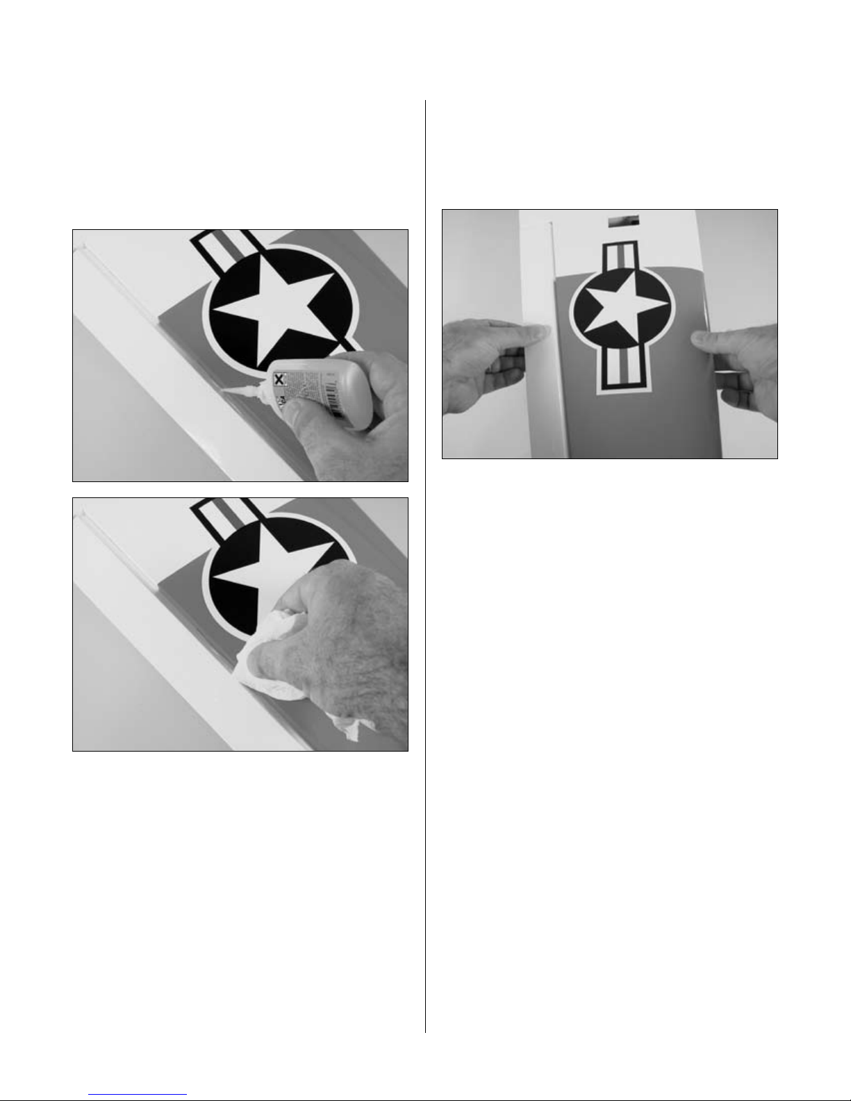
Step 5
Apply the decals. Use the photos on the box to aid in their
location.
Step 3
Lightly sand the inside edge of the canopy and slightly
inside the line drawn on the hatch using medium
sandpaper.
Step 6
Position the tail cone. Drill two 3/32" (2.5mm) holes
through the tail cone and into the mounting flanges.
Secure the tail cone using two #2 x 1/2" sheet metal
screws.
55
Page 56

Recommended CG Location
An important part of preparing the aircraft for flight
is properly balancing the model. This is especially
important when various engines are mounted.
Caution: Do not inadvertently skip this step!
The recommended Center of Gravity (C.G.) location for
the T-34 is 4
wing against the fuselage. If necessary, move the battery
pack or add weight to either the nose or the tail until the
correct balance is achieved. Stick-on weights are available
at your local hobby store and work well for this purpose.
3
/4" (121mm) behind the leading edge of the
Recommended Control Throws
The amount of control throw should be adjusted as closely
as possible using mechanical means, rather than making
large changes electronically at the radio. By moving
the position of the clevis at the control horn toward the
outermost hole, you will decrease the amount of control
throw of the control surface. Moving it toward the control
surface will increase the amount of throw. Moving the
pushrod wire at the servo arm will have the opposite
effect: Moving it closer to center will decrease throw,
and away from center will increase throw. Work with a
combination of the two to achieve the closest or exact
control throws listed.
Aileron 7/16" up 3/8" down
Elevator 5/8" up 5/8" down
Rudder 1" right 1" left
Note: Control throws are measured at the widest part of
the elevator, rudder, and aileron unless noted otherwise.
Once the control throws have been set, use the supplied
tubing on each clevis to prevent them from opening
during flight.
56
Page 57

Adjusting the Engine
Step 1
Completely read the instructions included with your
engine and follow the recommended break-in procedure.
Step 2
At the field, adjust the engine to a slightly rich setting at
full throttle and adjust the idle and low-speed needle so
that a consistent idle is achieved.
Pre-Flight
Charge both the transmitter and receiver pack for your
airplane. Use the recommended charger supplied with
your particular radio system, following the instructions
provided with the radio. In most cases, the radio should
be charged the night before going out flying.
Step 3
Before you fly, be sure that your engine idles reliably,
transitions and runs at all throttle settings. Only
when this is achieved should any plane be considered
ready for flight.
Check the radio installation and make sure all the
control surfaces are moving correctly (i.e. the correct
direction and with the recommended throws). Test run
the engine and make sure it transitions smoothly from
idle to full throttle and back. Also ensure the engine is
tuned according to the manufacturer’s instructions, and it
will run consistently and constantly at full throttle when
adjusted.
Check all the control horns, servo horns and clevises to
make sure they are secure and in good condition. Replace
any items that would be considered questionable. Failure
of any of these components in flight would mean the loss
of your aircraft.
Range Test Your Radio
Range check your radio system before each flying session.
This is accomplished by turning on your transmitter with
the antenna collapsed. Turn on the radio in your airplane.
With your airplane on the ground, you should be able
to walk 30 paces away from your airplane and still have
complete control of all functions. If not, don’t attempt
to fly! Have your radio equipment checked out by the
manufacturer.
57
Page 58

2006 Official AMA
National Model Aircraft Safety Code
GENERAL
1) I will not fly my model aircraft in sanctioned
events, air shows or model flying demonstrations until
it has been proven to be airworthy by having been
previously, successfully flight tested.
2) I will not fly my model higher than approximately
400 feet within 3 miles of an airport without notifying
the airport operator. I will give right-of-way and avoid
flying in the proximity of full-scale aircraft. Where
necessary, an observer shall be utilized to supervise
flying to avoid having models fly in the proximity of
full-scale aircraft.
3) Where established, I will abide by the safety rules
for the flying site I use, and I will not willfully and
deliberately fly my models in a careless, reckless and/
or dangerous manner.
4) The maximum takeoff weight of a model is 55
pounds, except models flown under Experimental
Aircraft rules.
5) I will not fly my model unless it is identified with
my name and address or AMA number, on or in the
model. (This does not apply to models while being
flown indoors.)
6) I will not operate models with metal-bladed
propellers or with gaseous boosts, in which gases
other than air enter their internal combustion
engine(s); nor will I operate models with extremely
hazardous fuels such as those containing
tetranitromethane or hydrazine.
7) I will not operate models with pyrotechnics (any
device that explodes, burns, or propels a projectile
of any kind) including, but not limited to, rockets,
explosive bombs dropped from models, smoke
bombs, all explosive gases (such as hydrogen-filled
balloons), or ground mounted devices launching a
projectile. The only exceptions permitted are rockets
flown in accordance with the National Model Rocketry
Safety Code or those permanently attached (as per
JATO use); also those items authorized for Air Show
Team use as defined by AST Advisory Committee
(document available from AMA HQ). In any case,
models using rocket motors as a primary means of
propulsion are limited to a maximum weight of 3.3
pounds and a G series motor. (A model aircraft is
defined as an aircraft with or without engine, not able
to carry a human being.)
8) I will not consume alcoholic beverages prior to,
nor during, participation in any model operations.
9) Children under 6 years old are only allowed
on the flight line as a pilot or while receiving
flight instruction.
RADIO CONTROL
1) I will have completed a successful radio equipment
ground range check before the first flight of a new or
repaired model.
2) I will not fly my model aircraft in the presence
of spectators until I become a qualified flier, unless
assisted by an experienced helper.
3) At all flying sites a straight or curved line(s) must
be established in front of which all flying takes place
with the other side for spectators. Only personnel
involved with flying the aircraft are allowed at or in
the front of the flight line. Intentional flying behind the
flight line is prohibited.
4) I will operate my model using only radio control
frequencies currently allowed by the Federal
Communications Commission. (Only properly
licensed Amateurs are authorized to operate
equipment on Amateur Band frequencies.)
58
Page 59

2006 Official AMA
National Model Aircraft Safety Code
5) Flying sites separated by three miles or more
are considered safe from site-to site interference,
even when both sites use the same frequencies. Any
circumstances under three miles separation require
a frequency management arrangement, which may
be either an allocation of specific frequencies for
each site or testing to determine that freedom from
interference exists. Allocation plans or interference
test reports shall be signed by the parties involved
and provided to AMA Headquarters. Documents of
agreement and reports may exist between (1) two
or more AMA Chartered Clubs, (2) AMA clubs and
individual AMA members not associated with AMA
Clubs, or (3) two or more individual AMA members.
6) For Combat, distance between combat engagement
line and spectator line will be 500 feet per cubic
inch of engine displacement. (Example: .40 engine
= 200 feet.); electric motors will be based on
equivalent combustion engine size. Additional safety
requirements will be per the RC Combat section of the
current Competition Regulations.
7) At air shows or model flying demonstrations, a
single straight line must be established, one side of
which is for flying, with the other side for spectators.
8) With the exception of events flown under AMA
Competition rules, after launch, except for pilots or
helpers being used, no powered model may be flown
closer than 25 feet to any person.
9) Under no circumstances may a pilot or other
person touch a powered model in flight.
Organized RC Racing Event
10) An RC racing event, whether or not an AMA Rule
Book event, is one in which model aircraft compete
in flight over a prescribed course with the objective of
finishing the course faster to determine the winner.
A. In every organized racing event in which
contestants, callers and officials are on the course:
1. All officials, callers and contestants must properly
wear helmets, which are OSHA, DOT, ANSI, SNELL or
NOCSAE approved or comparable standard while on
the racecourse.
2. All officials will be off the course except for the
starter and their assistant.
3.”On the course” is defined to mean any area beyond
the pilot/staging area where actual flying takes place.
B. I will not fly my model aircraft in any organized
racing event which does not comply with paragraph A
above or which allows models over 20 pounds unless
that competition event is AMA sanctioned.
C. Distance from the pylon to the nearest spectator
(line) will be in accordance with the current
Competition Regulations under the RC Pylon Racing
section for the specific event pending two or three
pylon course layout.
11) RC night flying is limited to low-performance
models (less than 100 mph). The models must be
equipped with a lighting system that clearly defines
the aircraft’s position in the air at all times.
59
Page 60

9283
®
© 2006 Horizon Hobby, Inc.
4105 Fieldstone Road
Champaign, Illinois 61822
(877) 504-0233
horizonhobby.com
 Loading...