

Page 1
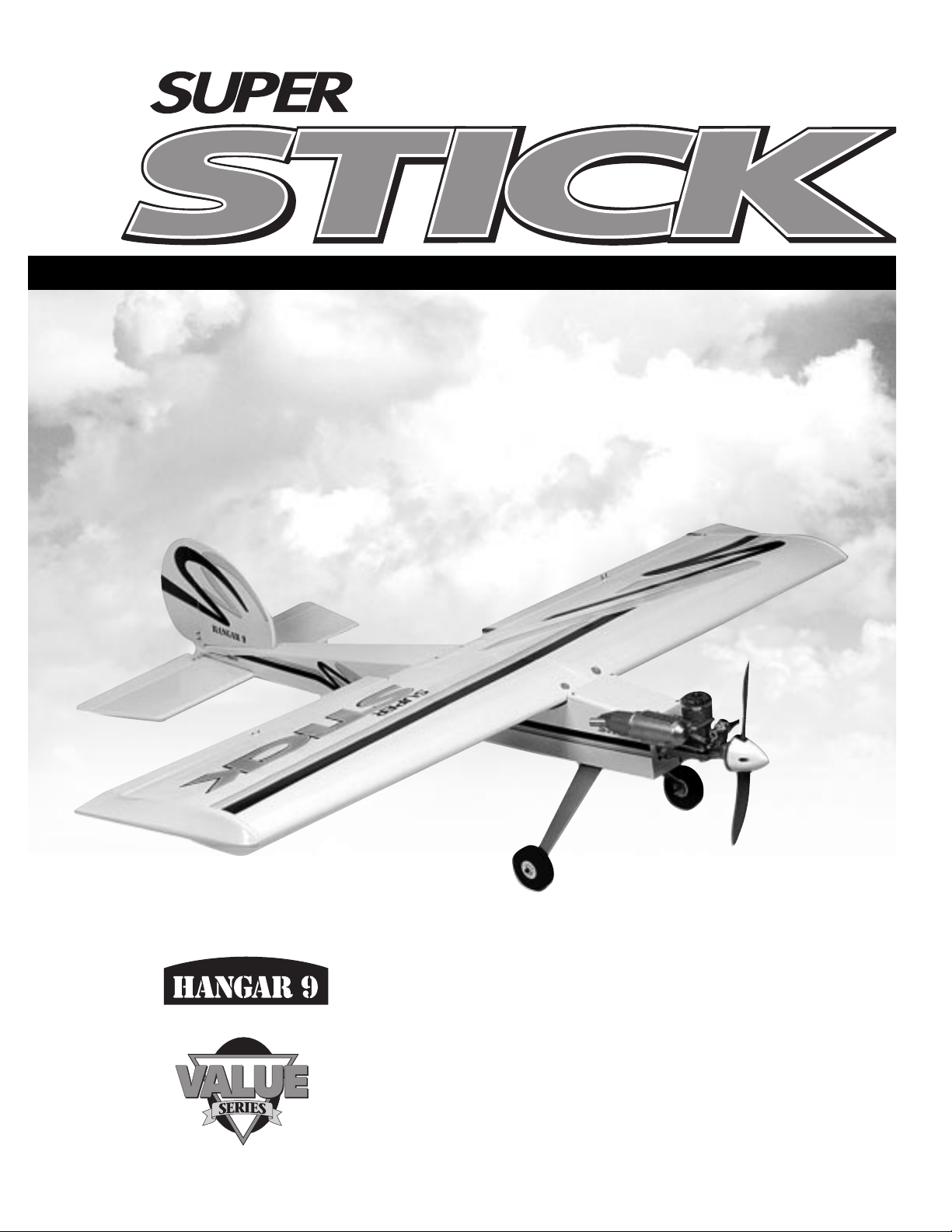
WE GET PEOPLE FLYING
TM
TM
INSTRUCTION MANUAL
➤ Specifications for .40
Wingspan: 52-3/4
"
Length: 48
"
Wing Area: 593 sq.in.
Weight (Approx): 5 – 5.5 lbs.
Recommended Engines:
.40 – .46 2-Cycle
.50 – .56 4-Cycle
➤ Specifications for .60
Wingspan: 59
"
Length: 54
"
Wing Area: 738 sq.in.
Weight (Approx): 7.25 – 7.75 lbs.
Recommended Engines:
.61 – .75 2-Cycle
.65 – .80 4-Cycle
• 90% Pre-Built
• Build as Tail dragger or Tricycle Landing Gear System
Page 2

TABLE OF CONTENTS
Introduction 3
Additional Equipment Required 4
Tools and Supplies Required 4
Contents of Kit 5
Field Equipment Required 6
Optional Field Equipment 7
Section 1: Assembling the Wings 8
Section 2: Joining the Wing Halves 9
Section 3: Installing the Aileron Servos 13
Section 4: Bolt Wing to Fuselage 14
Section 5: Installing Horizontal Stabilizer 14
Section 6: Installing Vertical Fin 16
Section 7: Tail Dragger or Tricycle Landing Gear 17
Section 8: Installing the Tail Wheel Assembly 18
Section 9: Hinging the Rudder and Elevator 20
Section 10: Installing the Control Horns 20
Section 11: Installing Main Landing Gear Block — Tail Dragger 22
Section 12: Installing Main Landing Gear Block — Tricycle 23
Section 13: Installing the Main Landing Gear 23
Section 14: Installing the Nose Gear 25
Section 15: Assembling and Installing the Fuel Tank 26
Section 16: Installing the Servo Tray 28
Section 17: Installing the Engine 29
Section 18: Installing the Spinner 30
Section 19: Installing the Radio System 30
Section 20: Installing the Aileron Linkages 32
Section 21: Assembling Elevator & Rudder Pushrods 33
Section 22: Installing the Throttle Linkage 35
Section 23: Installing the Nose Wheel Linkage 36
Section 24: Control Throw Recommendation 37
Section 25: Balancing the Super Stick 37
Pre-Flight Check 38
Pre-Flight at the Flying Field 39
AMA Safety Code 40
Page 3

INTRODUCTION
WARNING
Congratulations on purchasing the Hangar 9 Super Stick.
This is the ideal second airplane for modelers capable of
flying a trainer-type aircraft. In a few short evenings,this
90% pre-built aircraft will be ready for its debut at the
flying field.
This manual has been written to ensure that you achieve
the best performance and maximum enjoyment from your
Super Stick. It is important to carefully read and follow the
instructions in this manual prior to flying.
An R/C aircraft is not a toy! If misused,it can cause serious
bodily harm and damage to property. Fly only in open
areas,preferably AMA (Academy of Model Aeronautics)
approved flying sites, following all instructions included
with your radio and engine.
Page 4
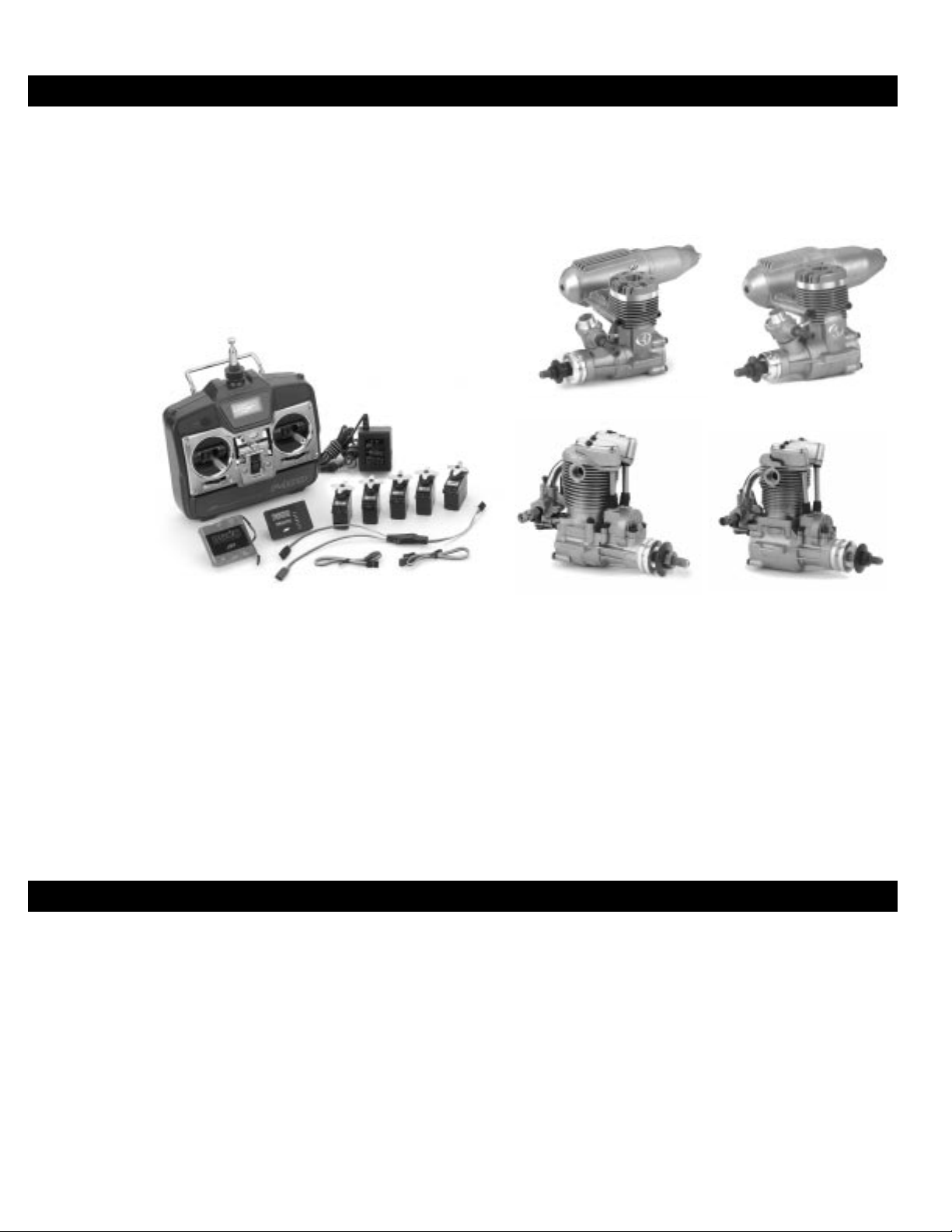
ADDITIONAL EQUIPMENT REQUIRED
TOOLS AND SUPPLIES REQUIRED
➤ Equipment Needed
4 Channel Transmitter (minimum)
5 Standard Servos
Standard 450–650 mAh Receiver Battery Pack
2 Aileron Extensions and/or 1Y-harness
➤ Note: If more than a 4-channel radio is used,
than Y-harness is not necessary.
Super Stick 40:
.40–.46 2-Cycle Engines
.45–.56 4-Cycle Engines
Super Stick 60:
.61–.75 2-Cycle Engines
.65–.80 4-Cycle Engines
➤ Engine Recommendations
➤ Recommended JR Systems
JR F400 FM (Optional Y-harness required)
JR XF642FM
JR XP783
JR XP8103
(5 servos required)
➤ Recommended 2-Cycle Engines
Super Stick 40:
Thunder Tiger Pro .40
Thunder Tiger Pro .46
Thunder Tiger .42 Sport
Webra Speed .40 Sport
Super Stick 40:
Saito .50
Saito .50GK
Saito .56
Saito .56GK
Super Stick 60:
Thunder Tiger Pro .60
ASP .61
ASP .75
Super Stick 60:
Saito .65
Saito .65GK
Saito .80
Saito .80GK
➤ Adhesives
Thick CA (cyanoacrylate) glue
6-minute epoxy
30-minute epoxy
Blue Locktite 242
➤ Tools
Drill
Drill bits:
1/16",3/32”,5/32
"
Phillips screwdrivers
Z-bend pliers
Pliers
Small round file
Moto-tool
with sanding drum
Hobby knife
with #11 blade
Mixing stick
Epoxy brush
Medium sandpaper
Masking tape
Straight edge
Measuring devices
(ruler,tape measure,
90˚ triangle)
Scissors
Paper towels
Wax paper
Rubbing alcohol
Felt tipped pen
Fuel tubing
Clips (clothes pins,
➤ Recommended 4-Cycle Engines
Thunder Tiger .61Thunder Tiger .40
Saito .50 Saito .65
Page 5
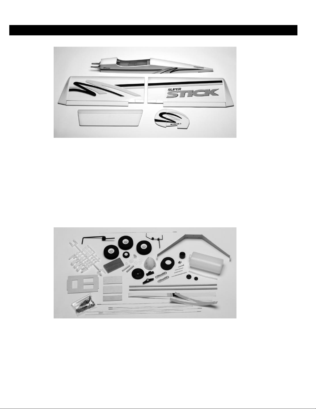
CONTENTS OF KIT
➤ Covered Parts
Fuselage
Left wing half with aileron
Right wing half with aileron
Vertical stabilizer with rudder
Horizontal stabilizer with elevator
➤ Small Parts
Pushrod and Accessories
1/8" plywood die-cut parts
Main landing gear
Nose landing gear
Spinner
Hardware bag
Plastic parts tree
Foam wheels (3)
Fuel tank and hardware
Tail wheel assembly
Landing gear block
Page 6
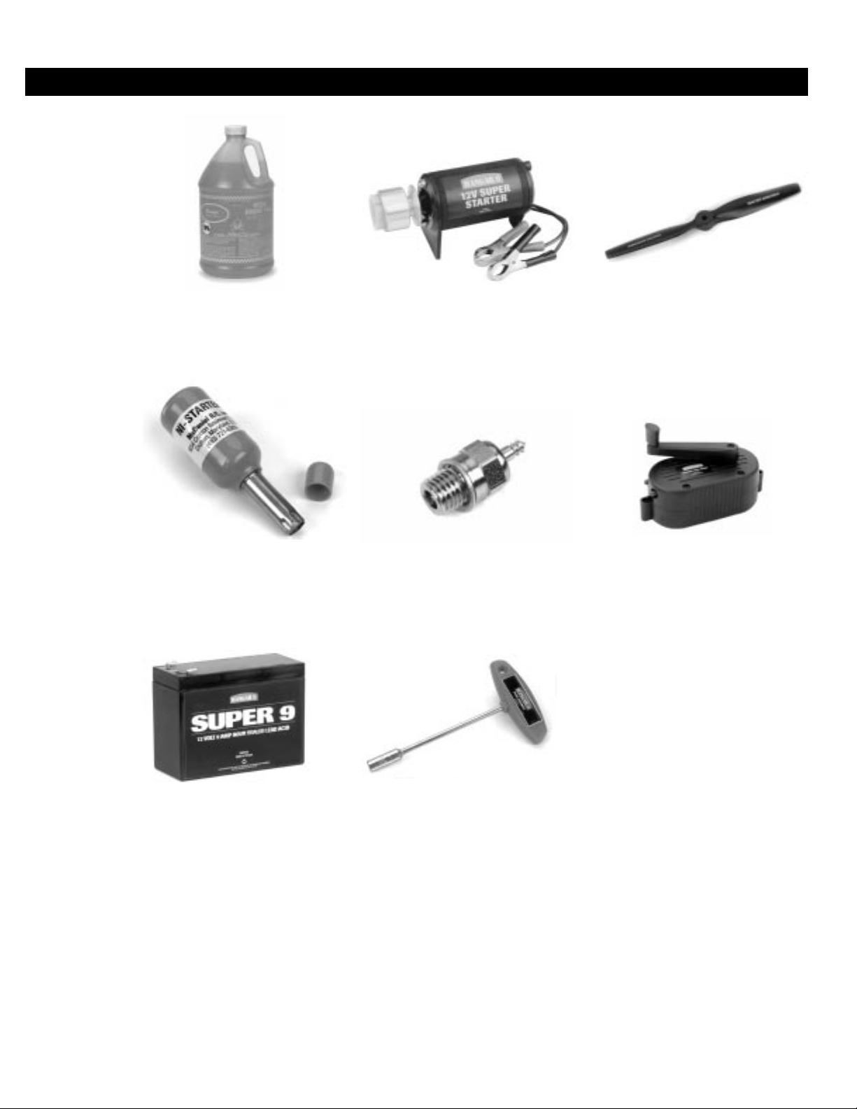
FIELD EQUIPMENT REQUIRED
Airplane Fuel
Glow Driver
12V Sealed Battery
12V Starter
Glow Plug
Glow Plug Wrench
Propeller
Manual Fuel Pump
Page 7
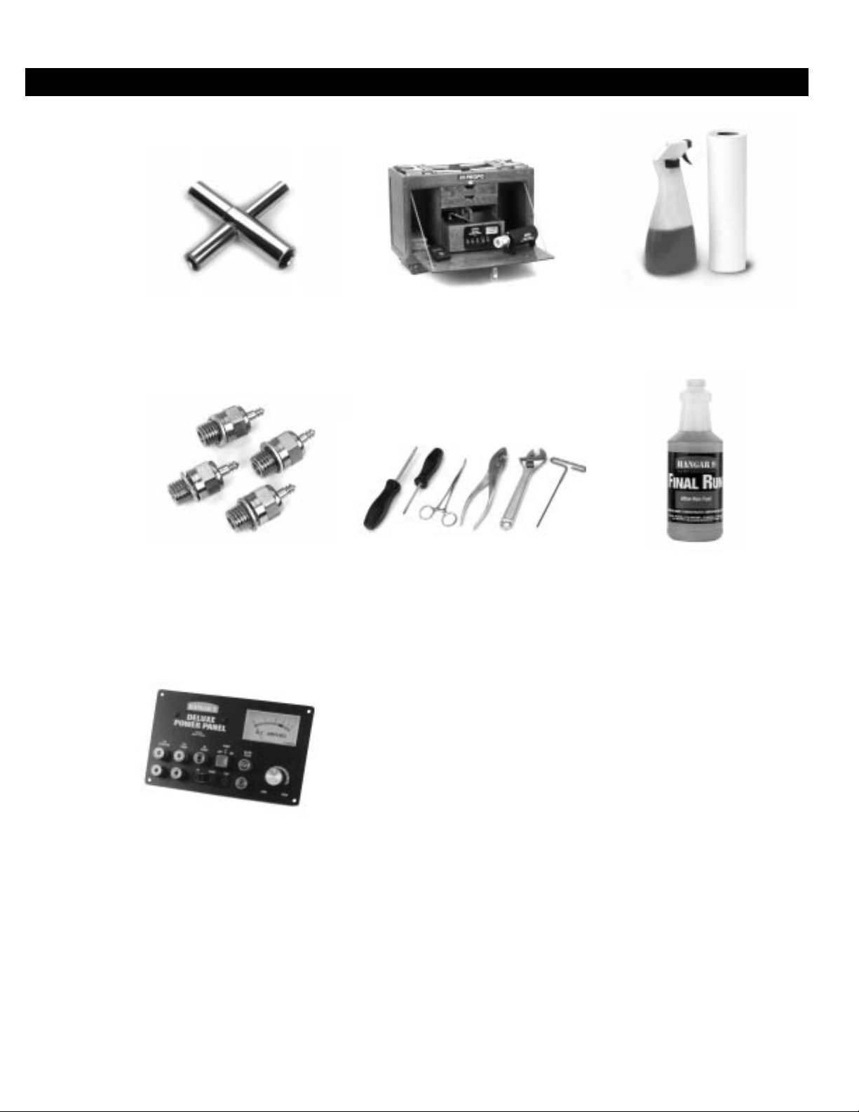
OPTIONAL FIELD EQUIPMENT
4-Wa y Wrench
Extra Glow Plugs
Power Panel
Field Box
Misc. Tools
Cleaner & Towels
After-Run Fuel
Page 8
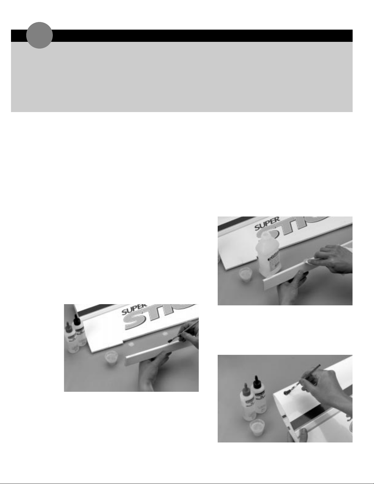
➤ Note:The ailerons are attached to the wing halves
from the factory, but the hinges are not glued in
place. The right aileron must go with the right wing
half and the left aileron must go with the left wing half.
Be sure to mark the aileron for correct identification
and top and bottom before you take it apart from the
wing.
1. Carefully remove the aileron from the right wing
panel by pulling straight out with even pressure.
2. Remove all four hinges from the aileron. Flex the
hinges accordingly so that they move freely.
3. Mix a small amount of 30-minute epoxy. Using either
a mixing stick or an epoxy brush,apply the epoxy
sparingly inside each hinge slot on the aileron.
Additionally,apply a small amount of epoxy to the top
and bottom half of each hinge. Insert the hinges into
the aileron accordingly until the hinge line is even with
the leading edge of the aileron.
4. Wipe off any excess epoxy using a paper towel and
rubbing alcohol.
➤ Hint: Lightly coat both ends of the ailerons with
epoxy,if they don’t have covering on them;this will
prevent the ailerons from becoming fuel-soaked. You
can mix a small amount of rubbing alcohol (one part
alcohol to three parts epoxy) into the epoxy to thin
it. This will make for a thinner coat of epoxy which
prevents a thick build-up on the ends of the ailerons.
This is a common way to “fuel proof” bare wood.
5. The bolt holes on each wing half are pre-drilled.
Locate the holes that are under the covering and
carefully cut-out the covering with your hobby knife.
Lightly coat the inside of the holes with your thinned
epoxy. Only use just enough to have a thin coat. Too
much will not allow the wing bolts to pass through.
➤ Parts Needed
Right wing panel with aileron & hinges
Left wing panel with aileron & hinges
➤ Tools & Adhesives Needed
30-minute epoxy
Paper towels
Rubbing alcohol
Mixing stick
Epoxy brush
Ruler
ASSEMBLING THE WINGS
1
Page 9
ASSEMBLING THE WINGS continued
1
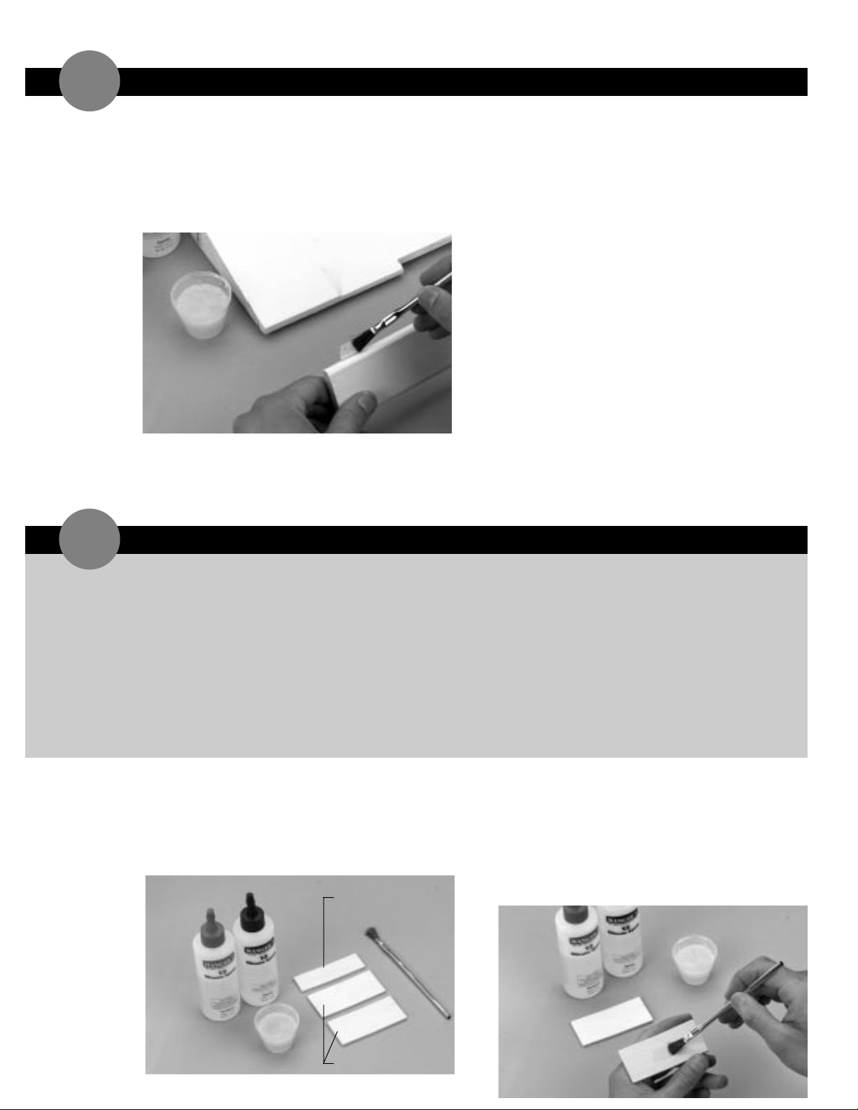
6. Mix a small amount of 30-minute epoxy to install the
aileron with affixed hinges onto the wing half. Apply
epoxy to the top and bottom of the remaining half of
each hinge. Using either a mixing stick or an epoxy
brush,apply epoxy inside each hinge slot on the wing.
7. Replace the aileron on the right wing half,ensuring
that the hinges are properly aligned. The gap between
the aileron and the wing should remain a constant
1/16",or as tight as possible so the movement of the
aileron is not impaired.
8. Carefully wipe off any excess epoxy using a paper
towel and rubbing alcohol.
9. Repeat the procedures above for the left wing half.
10. Allow the epoxy to fully cure before proceeding to
the next section.
1. Carefully remove the three individual spar joiners
from the die-cut plywood sheet. Two of the spar
joiners are the same size and one is smaller. The two
larger pieces are the main spar joiners. The smaller
one of the three is the sub-spar joiner.
2. Mix a small amount, approximately 1/4 ounce,of
6-minute epoxy. Using either a mixing stick or epoxy
brush,apply the epoxy to one side of one of the main
spar joiners. Place the epoxied spar joiner on top of
the remaining main spar joiner. Align the upper and
lower edges of the spar joiners as well as the area
which has the slight “V” shape.
JOINING WING HALVES
2
6-minute epoxy
30-minute epoxy
Clips (e.g.,clothespins,
binder clips)
Rubbing alcohol
Paper towels
Masking tape
Hobby knife
String
Wax paper
Ruler
Pencil
Medium sandpaper
Mixing stick
Epoxy brush
Felt tipped pen
➤ Parts Needed
Right wing panel from Section 1
Left wing panel from Section 1
2 main joiners
1 sub spar joiner
Wing center tape
➤ Tools & Adhesives Needed
sub-spar joiner
main spar joiners
Page 10
JOINING WING HALVES continued
2
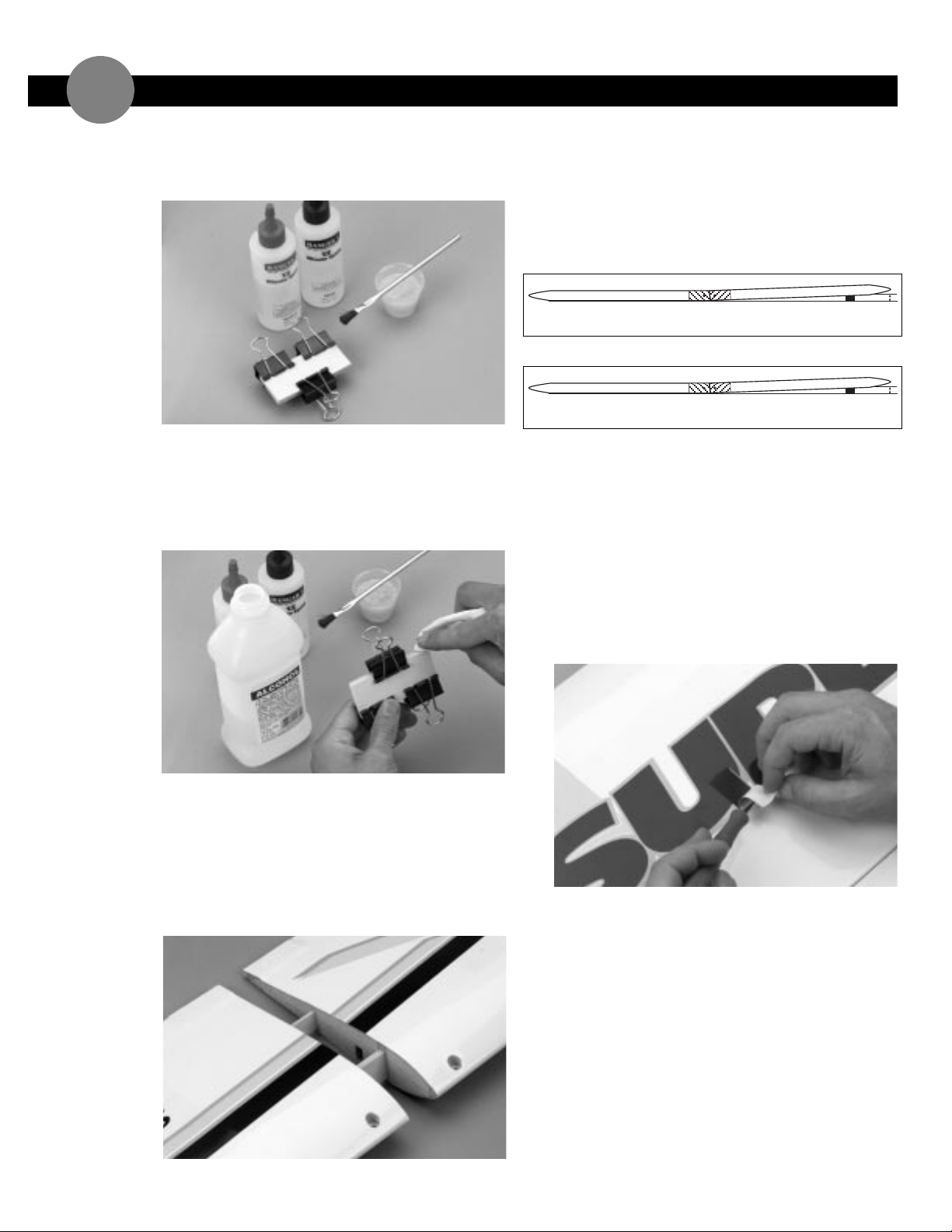
3. Clamp the two spar joiners together using three
clothespins or clips. Ensure that the joiners remain
aligned and that the clamps are firmly attached.
4. Wipe away the excess epoxy using a paper towel and
rubbing alcohol,being careful not to disturb the
alignment of the wing joiners.
➤ Note:The excess epoxy should be removed before it
cures.
5. Allow the epoxy to cure completely prior to
removing the clamps.
6. Trial fit the main spar and the sub-spar joiner into one
of the wing panels. It should insert easily. Now slide
the other wing half onto the main spar joiner and subspar until the wing panels meet.
7. Check for the correct dihedral angle. Place the wing
on a large,flat surface with one wing panel resting on
the surface. The opposite wing tip should be exactly
3/8"(for .40) or 1/2"(for .60) from the surface
(see illustrations below). If necessary,sand the main
spar joiner and sub-spar until this is achieved.
8. Before final assembly of the wing halves,it is now a
good time to install a method of pulling through your
aileron servo wires. Locate on each wing half the
location of the servo. You will be able to identify this
by a solid square shape with a rectangle cut-out in the
center of the wing half under the covering that is
roughly the size of the bottom of your servo. Take
your hobby knife,with a sharp blade,and cut-out the
covering were the servo will be installed. You do not
need to install the servos and servo extensions at this
time,this is simply a method to pull them through the
wing when needed.
.40 size
.60 size
1/2 inches
3/8 inches
Page 11
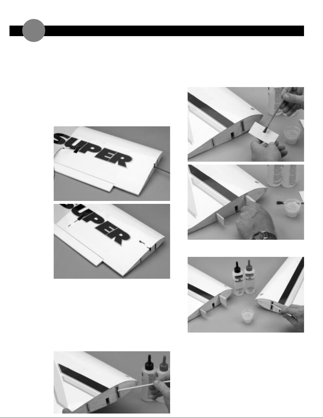
➤ Hint:You can feed music wire or an extra pushrod
that you may have around (or take a coat hanger and
straighten it) through the pre-cut root rib opening
(the end were the spar joiners are located). Carefully
insert it inside the wing half and through each of the
pre-cut openings of the wing ribs until it is at the
opening for the servo (reach inside the servo opening
to retrieve). Tape a piece of string to it and carefully
pull it through,leaving both ends accessible (a shoe
string works well for this). Now take a piece of tape
and tape the ends of the string to the wing half. Do
this to both wing halves.
9. Mix up approximately three ounces of 30-minute
epoxy.
➤ Note:When joining the wing halves, it is extremely
important to use plenty of epoxy.
10. Use a mixing stick or scrap piece of wood to apply a
generous amount of epoxy into the main and sub-spar
joiner cavity of one wing half. Ensure that the epoxy
is applied to all sides of the cavity wall.
11. Coat one half of the spar joiners with epoxy. Install
the epoxy-coated side of the spar joiners into the
spar joiner cavity. Be sure to install the joiners all the
way into the spar cavity. Make sure the “V” is
positioned correctly,so that it creates positive
dihedral in the wing.
12. Apply a generous amount of epoxy into the joiner
cavity of the other wing half.
JOINING WING HALVES continued
2
Page 12
JOINING WING HALVES continued
2
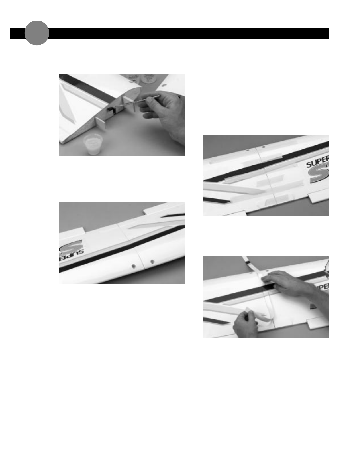
13. Smear epoxy on all sides of the exposed area of the
spar joiners and uniformly coat both wing roots with
epoxy.
14. Carefully slide the two wing halves together ensuring
that they are accurately aligned. Firmly press the two
halves together,allowing the excess epoxy to run out.
Using rubbing alcohol and a paper towel,clean off the
excess epoxy. There should not be any gap between
the wing halves.
15. Apply masking tape to hold the wing together
securely while the epoxy cures. Place the wing on a
large,flat surface. With one wing panel lying flat on
the surface,the opposite wing tip should be propped
up exactly 3/8"(for .40 size) or 1/2"(for .60 size)
from the surface. Allow the wing joint to dry
overnight.
➤ Note: It is a good idea to place a sheet of waxed
paper under the center joint of the wing so that any
excess epoxy will not adhere to the surface of the
work area.
16. When the wing center joint is completely dry,remove
the masking tape and apply the included trim tape to
cover the center joint. Be really careful to match the
stripes on the wing center tape to the stripes on top
of the wing.
Page 13
➤ Parts Needed
Assemble wing
2 standard size servos with mounting hardware
2 servo extensions (6"or 9")
➤ Tools & Adhesives Needed
Hobby knife
Masking tape
INSTALLING THE AILERON SERVOS
3
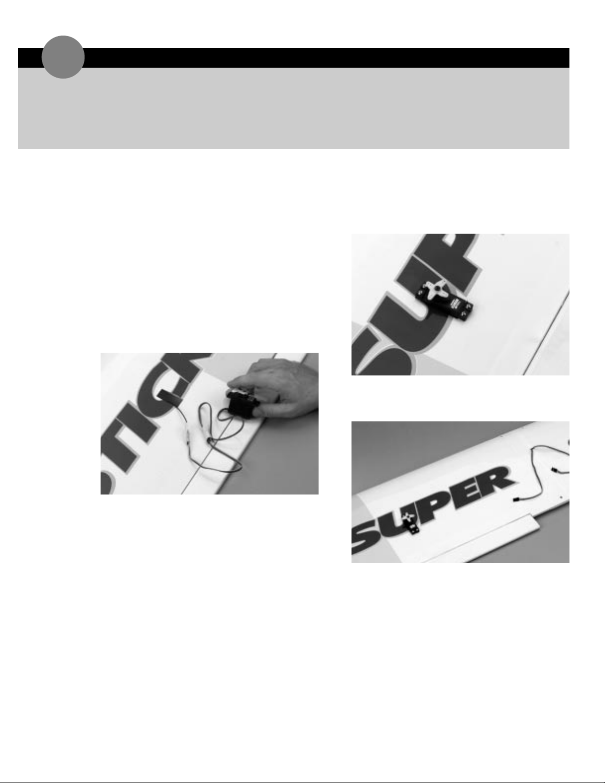
1. Install the recommended servo hardware supplied
with your radio system onto your servos (grommets
and eyelets). Install a minimum 6"servo extension
onto each of your aileron servos.
➤ Hint: It is always good procedure to tape the
extension connector and the servo lead connector
together to insure that they will not become
unplugged inside the wing.
2. With the servo extension securely fastened to the
servo lead,tape the end of the servo extension to the
string you installed onto the end that exits were the
servo will be installed.
3. Carefully pull the string through the wing until you
have the servo extension plug exit at the center of
the wing at the wing root.
4. Install the servo into the aileron servo slot.
➤ Note: It does not matter which way the servo is
installed into the slot;in other words,if the servo
horn is closer to the aileron.
5. Securely fasten the servo in the aileron slot with four
of the servo mounting screws supplied with your
radio system.
6. Follow steps 1– 5 for the other aileron servo.
Page 14
➤ Parts Needed
Fuselage
4 wing bolts & washers
➤ Tools & Adhesives Needed
Hobby knife or round file
Phillips screwdriver
➤ Parts Needed
Horizontal Stabilizer
Fuselage
Assembled wing
➤ Tools & Adhesives Needed
INSTALLING HORIZONTAL STABILIZER
5
➤ Note:Your Hangar 9 Super Stick comes from the
factory with pre-installed blind nuts in the fuselage
and pre-drilled holes in the wing for bolting the wing
to the fuselage.
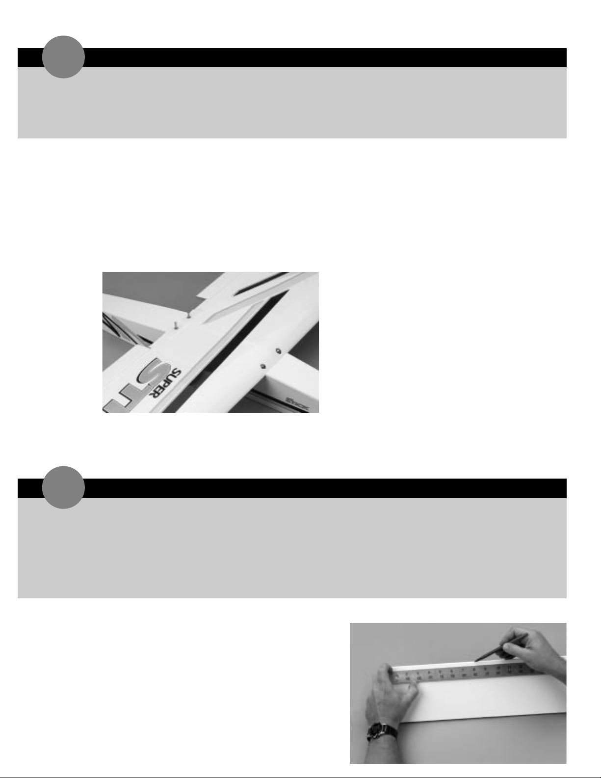
1. Place the wing onto the wing saddle of the fuselage,
approximately aligning the wing center with the
center line of fuselage.
2. Insert each of the wing bolts into the wing.
3. Carefully thread each bolt just a few turns into the
installed blind nuts of the fuselage.
➤ Note: If the wing bolts are not perfectly aligned and
you can’t get bolts to thread into the blind nuts,
carefully use a round file and enlarge the pre-drilled
hole in the wing on the bolt hole that is not exactly
aligned. If you have to do this, it only requires that a
slight amount of material be removed. The wing bolts
may be hard to turn when you first install them, but it
will get easier in time. Be careful not to cross-thread
the bolts into the blind nuts.
4. After each wing bolt is started,tighten each bolt a
little at a time. Continue with each bolt until the wing
is securely tightened to the fuselage. Be careful not to
over-tighten.
➤
Note: Leave the wing on the fuselage for installing
the horizontal stabilizer.
➤ Note:Before assembling the tail,remove the elevator
and the hinges from the horizontal stabilizer. The
hinges and elevator will be installed later.
1. Measure and mark the center of the horizontal
stabilizer on its leading edge.
2. If you removed it from the previous section of this
manual,install the wing onto the fuselage.
Hobby knife
Ruler
Felt tipped pen
Pencil
30-minute epoxy
Paper towels
Rubbing alcohol
Mixing stick
Epoxy brush
Masking tape
BOLT WING TO FUSELAGE
4
Page 15
INSTALLING HORIZONTAL STABILIZER continued
5
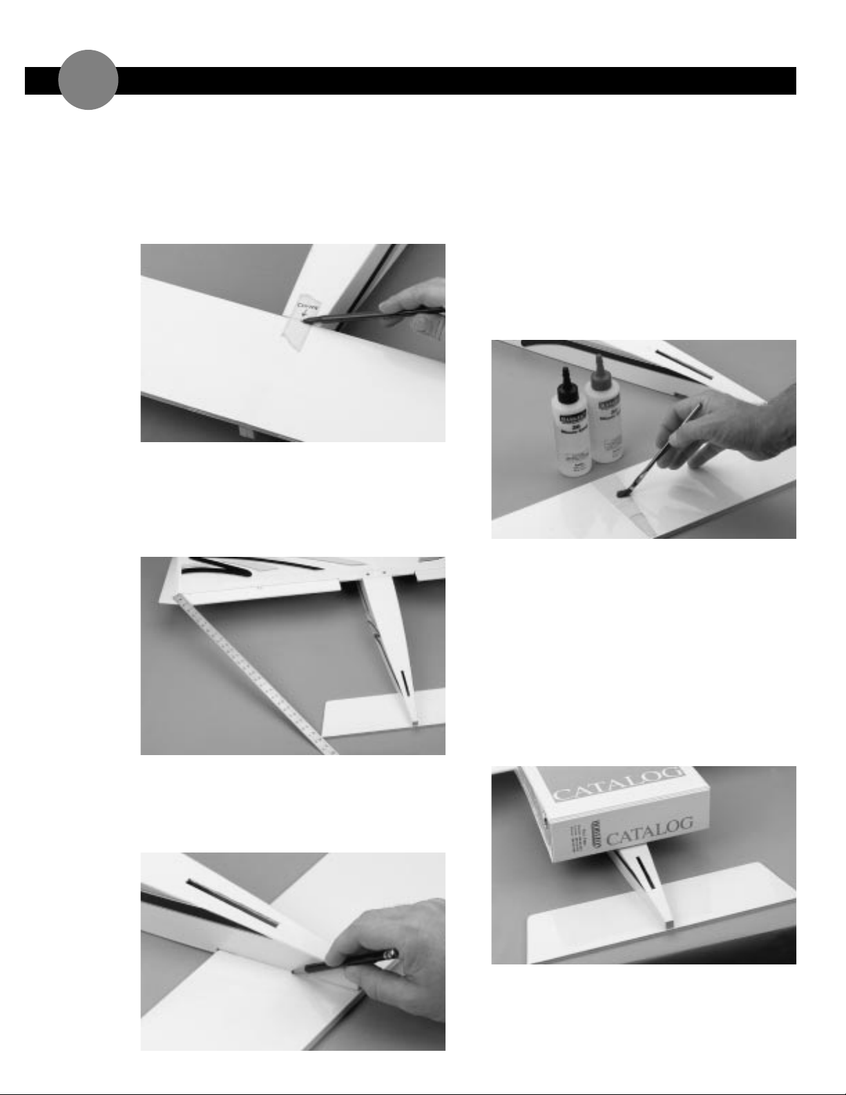
3. On the bottom of the aft end of the fuselage you will
find a notch for the horizontal stabilizer to be placed.
Make a center mark on the front of the saddle on the
fuselage and place the horizontal stabilizer into the
horizontal stabilizer saddle,aligning the two marks
you just made. Tape the leading edge of the stabilizer
to the fuselage to secure it for now.
4. Align the horizontal stabilizer by measuring from a
fixed point on the wing to the outside of the trailing
edge tip of the horizontal stabilizer. Be sure that the
leading edge stays on its center mark. Adjust the
stabilizer until you have an equal distance on both the
right and left sides of the stabilizer to the wing.
5. When you are satisfied with the alignment of the tail
to the wing,carefully mark the position with a pencil
at the junction where the horizontal stabilizer meets
the fuselage. The pencil should leave a slight
indentation in the covering.
6. Remove the horizontal stabilizer from the fuselage.
Using your hobby knife and a straight edge,carefully
cut the covering approximately 1/16"inside the lines
you drew. It is very important that you do not
press hard enough to cut into the wood as
doing so could weaken the horizontal stabilizer.
7. Mix approximately 1/4 ounce of 30-minute epoxy to
install the horizontal stabilizer. Using an epoxy brush
or mixing stick,spread the epoxy onto the top of the
horizontal stabilizer where it comes into contact with
the fuselage.
8. Lay the stabilizer onto a flat work surface and position
the fuselage onto it,making sure it is centered and
aligned as per Step 3 and 4.
➤ Hint: Reference the bare wood that you just exposed
to re-align the stabilizer. Place a heavy object (that
won’t damage the fuselage structure) on top of the
fuselage to press the stabilizer and fuselage together.
➤ Note: Be sure that the horizontal stabilizer and
fuselage are assembled on a good,flat surface and that
they are level with each other.
9. Wipe off any excess epoxy using a paper towel and
rubbing alcohol. Allow the epoxy to cure fully before
proceeding to the next step.
Page 16

6
1. On the rear of the fuselage,a slot is pre-cut in the
wood structure for the vertical fin. Using a sharp
hobby knife,cut away the covering on the top rear of
the fuselage where the vertical fin inserts into the
fuselage.
2. Remove the rudder and hinges from the vertical fin
if you have not already done so. These will be
assembled later.
3. Insert the vertical fin into the slot in the top of the
fuselage and check to make sure it is fully seated
down against the horizontal stabilizer. Make sure the
rear of the vertical fin (where the hinge slots are
located) is aligned with the rear of the fuselage.
➤ Note:The elevator should not be hinged to the
horizontal stabilizer at this time. It will also be
assembled later. Carefully mark with a pencil the
position of the vertical fin on both sides where it exits
the fuselage.
4. Remove the vertical fin and carefully cut away the
covering with a sharp hobby knife inside the lines you
marked in Step 3. Do not cut into the wood of
the fin when cutting the covering.
5. Mix up approximately 1/4 ounce of 30-minute epoxy
and apply it the vertical fin where it comes in contact
with the fuselage. Also apply epoxy to the base of the
fin where it comes in contact with the horizontal
stabilizer.
6. Insert the fin into the fuselage and wipe away any
excess epoxy.
7. Using a 90 degree triangle, make sure the fin is
perpendicular to the horizontal stabilizer. Use
masking tape to hold the vertical fin in place until it’s
completely dry.
➤ Parts Needed
Vertical tail
Fuselage
➤ Tools & Adhesives Needed
30-minute epoxy
Hobby knife
Pencil
Masking tape
Rubbing alcohol
Paper towels
90 degree triangle
Epoxy brush
Mixing stick
INSTALLING VERTICAL FIN
Page 17
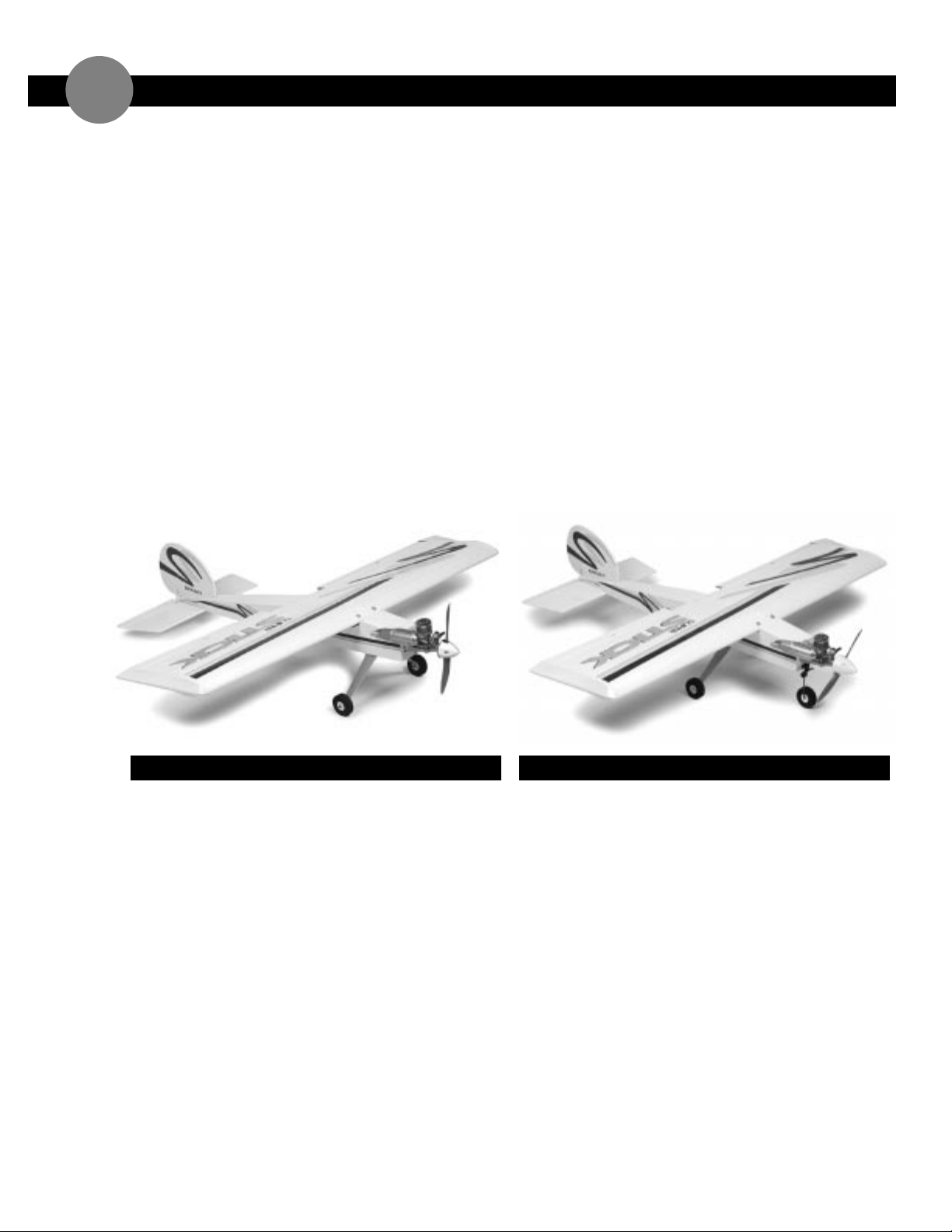
➤ Important! Please Read: Before proceeding any
further in the assembly of your Super Stick,you will
need to decide whether you want it to be equipped
with a tail dragger or tricycle landing gear system.
Experienced pilots prefer the tail dragger
configuration as its reduced weight and cleaner
aerodynamics give slightly better performance. The
position of the main gear is quite a bit ahead of the
center of gravity so nose overs are minimized.
If this is your first sport airplane,you’ll want to
consider the tricycle set-up. It provides even more
stable ground handling at only a slight weight and drag
penalty.
WHY A TAIL DRAGGER?
➤ Pros:
• Lighter weight — eliminates nose gear, nose
wheel and steering linkage
• Easier to install — no nose gear linkage
• Less aerodynamic drag — no nose gear to cut
through the air
• Cleaner looks
➤ Cons:
• Can nose over in tall grass
• Ground handling is slightly less stable,requiring
some right rudder input on takeoffs
• More likely to break the prop on rough landings
WHY A TRICYCLE?
➤ Pros:
• Super stable ground handling
• Superior for rough grass fields
• Improved prop protection
➤ Cons:
• Heavier — additional nose gear assembly
• More work to install — installation of linkage
to nose gear for steering control
TAIL DRAGGER OR TRICYCLE LANDING GEAR
7
Page 18
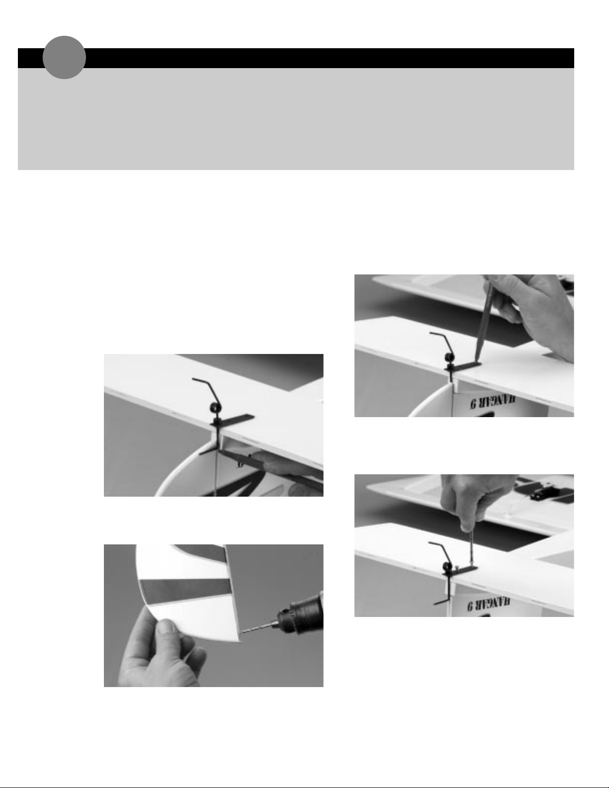
1. Insert three hinges into the pre-cut slots of the
rudder (do not glue at this time) and install the
rudder to the vertical fin.
2. Take the tail wheel assembly and place it in the
location to be installed on the bottom side of
horizontal stabilizer as shown.
3. The tail wheel’s guide wire will be installed into the
rudder. Mark the position where the hole is to be
drilled into the leading edge of the rudder for the
steering rod.
4. Remove the rudder. Using a 3/32"drill bit,drill into
the exact center of the leading edge of the rudder to
accept the tail wheel guide wire as shown.
5. Re-install the rudder with the tail wheel assembly and
mark the screw location for the tail wheel mounting
plate.
➤ Note: Using your hobby knife,make a small notch in
the horizontal stabilizer to allow the tail wheel
bracket to lay completely flat on the stabilizer.
6. Remove the rudder from the vertical fin and drill a
1/16"hole in the two screw locations. Install the tail
wheel assembly to the fuselage using the two 2.6mm
wood screws.
➤ Parts Needed
Tail wheel assembly
Tail wheel
2.6mm wood screws
Fuselage
Rudder
Elevator
Hinges
Tail wheel collar
Locking screw
➤ Tools & Adhesives Needed
Phillips screwdriver
Drill
Drill bits: 3/32", 1/16
"
Hobby knife
Pencil
INSTALLING THE TAIL WHEEL ASSEMBLY
8
Page 19
ASSEMBLING THE WINGS
1
INSTALLING THE TAIL WHEEL ASSEMBLY continued
8
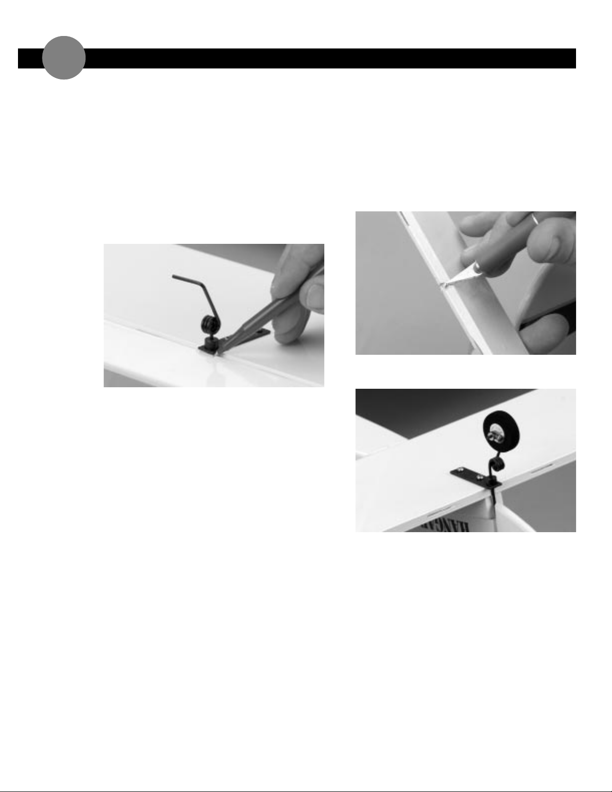
7. Temporarily install the rudder onto the vertical fin,
making sure the tail wheel guide wire is inserted into
the hole you previously drilled. Do not glue the
hinges at this time.
8. Take the elevator and insert the four hinges into the
hinge slots (do not glue the hinges at this time).
Temporarily install it onto the horizontal stabilizer.
9. Mark with your pencil the leading edge of the elevator
at the point where it contacts the tail wheel wire.
10. Remove the elevator. Using your hobby knife,
carefully cut a notch,at the mark on the elevator, the
same size as the tail wheel wire. Make the notch as
small as possible. Trial fit the elevator back onto the
horizontal stabilizer until you are satisfied with the fit.
Remove the elevator when done.
➤ Note:All gaps in the hinge lines of the control
surfaces should be as minimal as possible. No gap
is best.
11. Install the tail wheel onto the tail wheel assembly and
secure it with the supplied tail wheel collar and screw.
Page 20
HINGING THE RUDDER AND ELEVATOR
9
➤ Parts Needed
Fuselage
Rudder
Elevator
Hinges
➤ Tools & Adhesives Needed
30-minute epoxy
Mixing stick
Paper towels
Rubbing alcohol
➤ Parts Needed
Control horns
Control horn backplates
Control horn screws
Fuselage
Wing
➤ Tools & Adhesives Needed
Drill
Drill bit:1/16
"
Felt tipped pen or pencil
Phillips screwdriver
Ruler
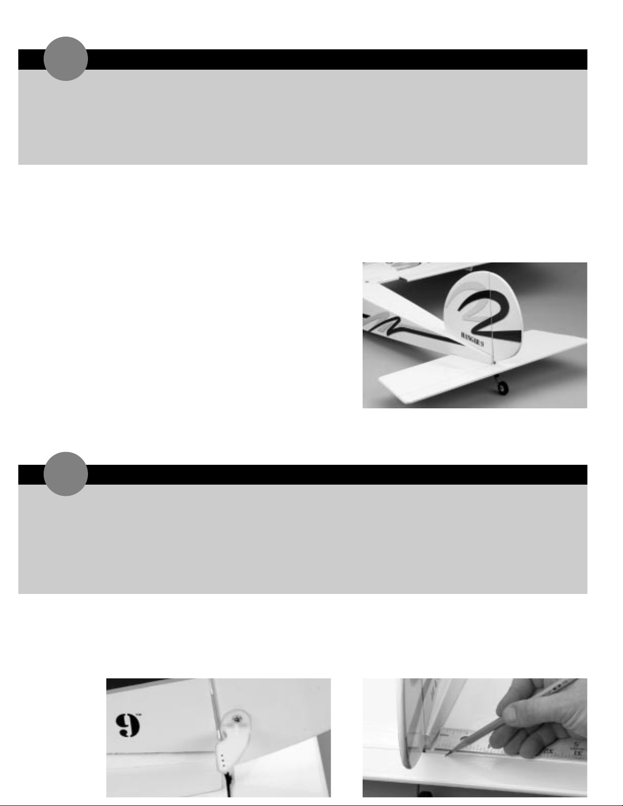
1. Take the 3 hinges for the rudder and flex them
accordingly so they move freely.
2. Mix a small amount of 30-minute epoxy. Using either
a mixing stick or a piece of scrap wood, apply the
epoxy sparingly inside each hinge slot on the rudder.
Additionally,apply a small amount of epoxy to the top
and bottom half of each hinge. Insert the hinges into
the rudder until the hinge line is even with the leading
edge of the rudder.
3. Apply epoxy to the remaining half of each hinge and
into the hinge slots in the vertical fin as well. Replace
the rudder onto the vertical fin.
➤ Note: Be sure to insert the tail wheel wire guide into
the rudder.
4. Carefully wipe away any excess epoxy using a paper
towel and rubbing alcohol.
5. Repeat this procedure to install the elevator to the
horizontal stabilizer.
INSTALLING THE CONTROL HORNS
10
➤ Important:When installing the control horns,it is
important that the holes in the control horns where
the pushrod attaches are directly in-line with the
control surface hinge line.
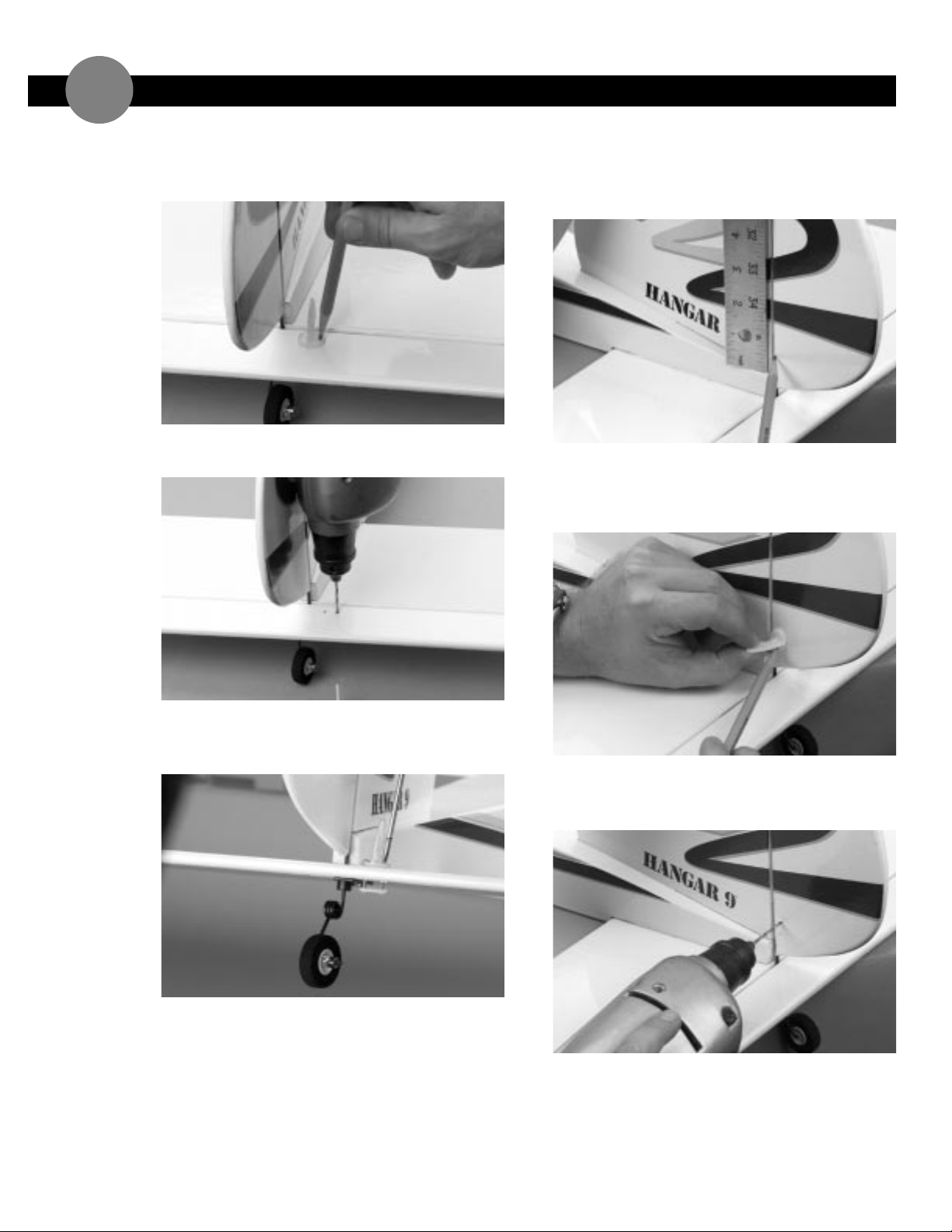
1. To locate the elevator control horns,measure over
1/2"to the right from the center of the tail section on
the fuselage. Mark the elevator as shown with a felt
tipped pen or a pencil. This mark will be the center of
the elevator control horn.
Page 21
INSTALLING THE CONTROL HORNS continued
10
2. Place the center of the control horn on the elevator
at the mark made in the previous step. Mark the hole
positions of the control horn.
3. Remove the control horn and drill two 1/16"holes
through the elevator as marked.
4. Attach the elevator control horn using the hardware
provided (two screws and backplate) and fasten in
place using a Phillips screwdriver.
5. Measure up 1/2"from the fuselage on the left side of
the rudder. Mark this location using a felt tipped pen
or a pencil. This mark will serve as the center for the
rudder control horn.
6. Center the control horn over the mark you have just
made and using a felt tipped pen or a pencil,mark the
mounting hole locations through both holes onto the
rudder.
7. Drill these holes with a 1/16"drill bit and install the
rudder control horn using the two screws and
backplate provided.
Page 22
INSTALLING THE CONTROL HORNS continued
10
➤ Parts Needed
Landing gear block
Fuselage
➤ Tools & Adhesives Needed
6-minute or 30-minute epoxy
Mixing stick or epoxy brush
Pencil
Medium sandpaper
INSTALLING THE MAIN LANDING GEAR BLOCK—TAIL DRAGGER
11
8. Turn the wing upside down. From the aileron servo
control horn that is attached to your servo (which
was installed earlier in this manual),mark the
location of the control horn directly in-line with the
control arm as shown. Remember to locate the
control horn holes so they are directly above the
hinge line.
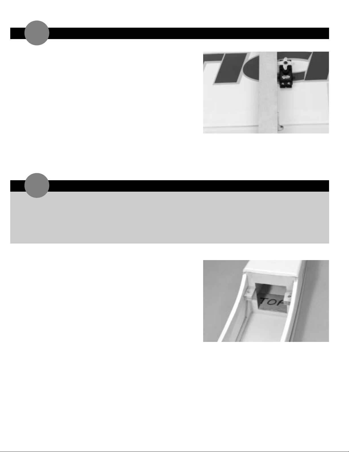
9. Repeat this procedure for the other aileron linkage.
➤ Note: If you are building your Super Stick with a
Tricycle gear system, skip this section.
1. Trial fit the landing gear block in the front of the
second former (F-2) of the fuselage. Take note of which
side of the block is down as this is the side to which
you will apply epoxy. (The firewall is what the engine
mount is installed onto and is the first former,F-1.)
➤ Note:The landing gear block will have a tight fit
against the fuselage sides. That way it will work with
either of the two landing gear setups. Sand the block
to fit.
2. After you have trial fit the landing gear block, mix up
approximately 1/4 ounce of 6-minute (or 30-minute)
epoxy.
3. Spread a generous amount of epoxy onto the bottom
of the landing gear block. Place the landing gear block
in the location for your main landing gear. Press firmly
into place and allow to dry.
Page 23
➤ Parts Needed
Landing gear block
Fuselage
➤ Tools & Adhesives Needed
6-minute or 30-minute epoxy
Mixing stick or epoxy brush
Pencil
1. Take the landing gear block and trial fit it in front of
the servo tray former of the fuselage. The servo tray
former is the third former back from the firewall of
the fuselage. Take note of which side of the block is
down as this is the side to which you will apply epoxy.
(The firewall is what the engine mount is installed
onto and is the first former,F-1.)
➤ Note:The landing gear block will not have a tight fit
against the fuselage sides. That way it will work with
either of the two landing gear setups. Sand the block
to fit.
2. After you have trial fit the landing gear block,mix up
approximately 1/4 ounce of 6-minute (or 30-minute)
epoxy.
3. Spread a generous amount of epoxy onto the bottom
of the landing gear block. Place the landing gear block
in the location for your main landing gear. Press firmly
into place and allow to dry.
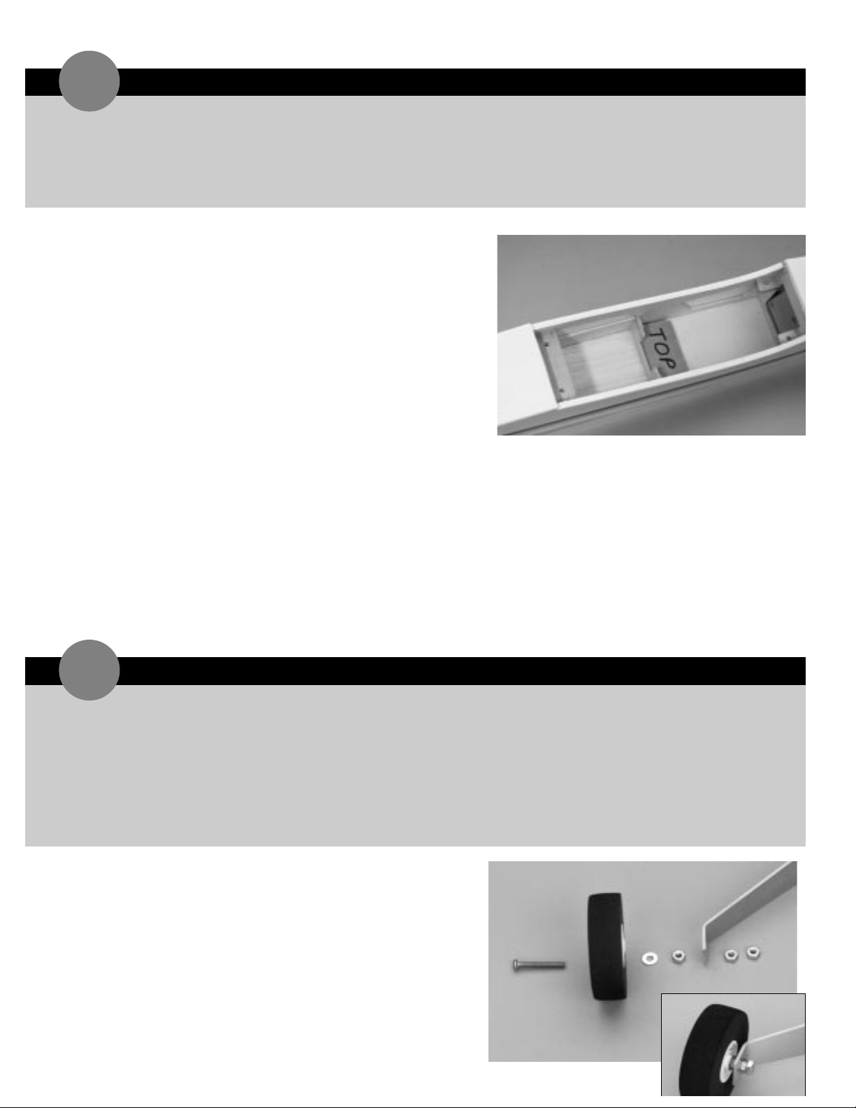
1. Attach the wheels to the aluminum landing gear using
the long 4 x 20mm screws. Note that each screw
passed through the wheel and then through a 4mm
washer,a 4mm nut,the landing gear and finally into a
second 4mm nut.
➤ Note: It is a good idea to put a second nut on the
end of the bolt. Be sure to use Blue Locktite 242 to
keep the nut from loosening.
INSTALLING THE MAIN LANDING GEAR BLOCK — TRICYCLE GEAR
12
➤ Parts Needed
Main landing gear
Fuselage
4 x 20mm bolts
6 nuts
Small wood screw
(not supplied — tail dragger only)
➤ Tools & Adhesives Needed
Felt tipped pen or pencil
Hobby knife
Drill
Drill bit: 1/16”, 5/32
”
Phillips screwdriver
INSTALLING THE MAIN LANDING GEAR
13
Page 24
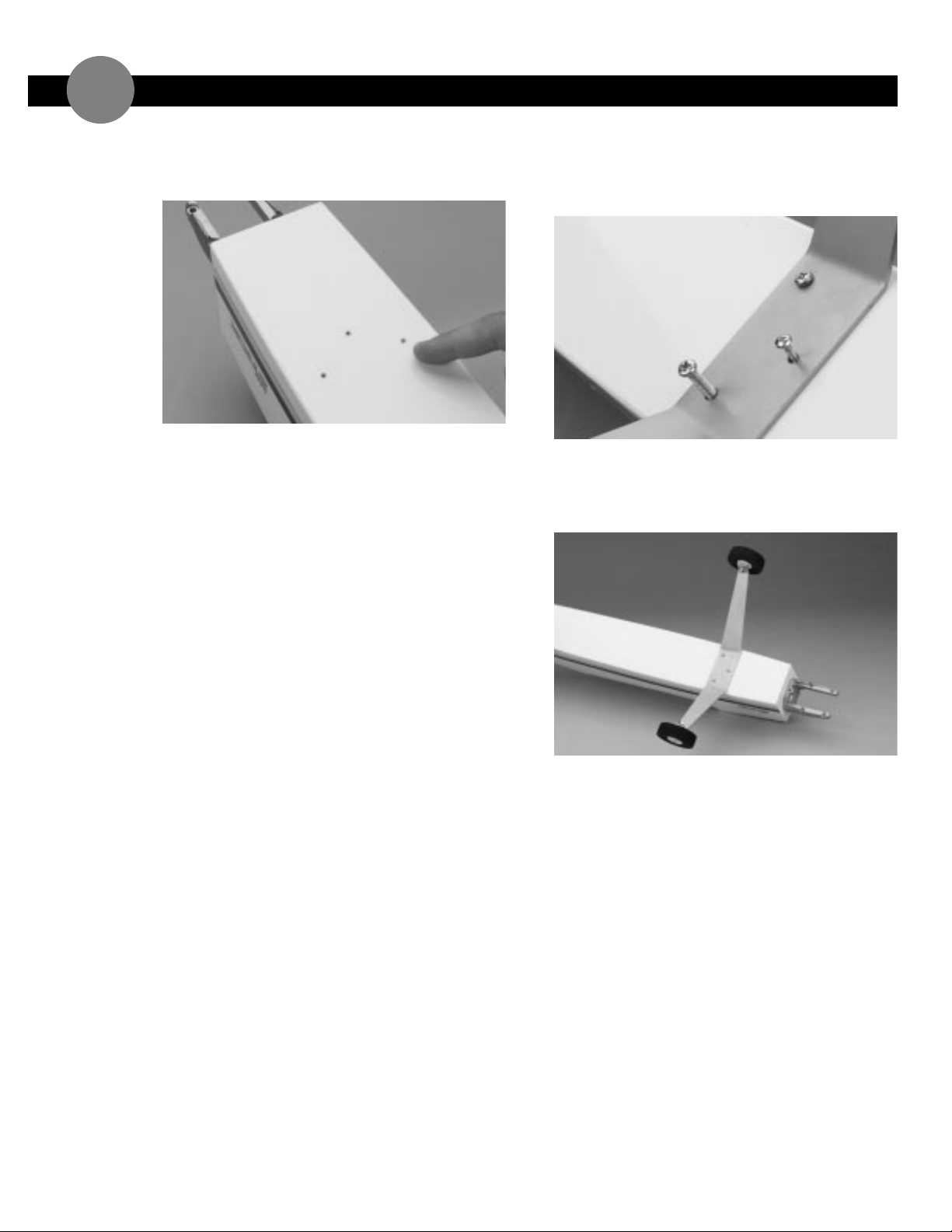
INSTALLING THE MAIN LANDING GEAR
13
2 . Locate the three hole indentations in the bottom of
the fuselage that are directly underneath where you
installed the landing gear block inside the fuselage.
➤ Note:If you are building your Super Stick as a tail
dragger,use a small wood screw (like a servo
mounting screw) for the middle hole of the landing
gear.
➤ Hint:Do not use the supplied bolt in this middle
location as it will interfere with the fuel tank. Instead,
use a small wood screw (not supplied).
3. From the bottom of the fuselage,drill out the two
outside holes with a 5/32"drill bit through the landing
gear block. Drill the middle hole using an 1/16" drill
bit.
4. Bolt the landing gear onto the fuselage with the
included hardware. Take the bolt and insert through
the landing gear and secure it with another washer
and a nut on the inside of the fuselage.
Page 25
ASSEMBLING THE WINGS
➤ Parts Needed
Nose gear
Nose gear control horn with 3mm screw
5/32"wheel collar with 3mm screw (3)
Nose wheel
Nose gear mount
➤ Tools & Adhesives Needed
Phillips screwdriver
Blue Locktite 242
Drill
Drill bit:1/16
"
Moto-tool
➤ Note:If you are building your Super Stick as a tail
dragger,skip to the next section.
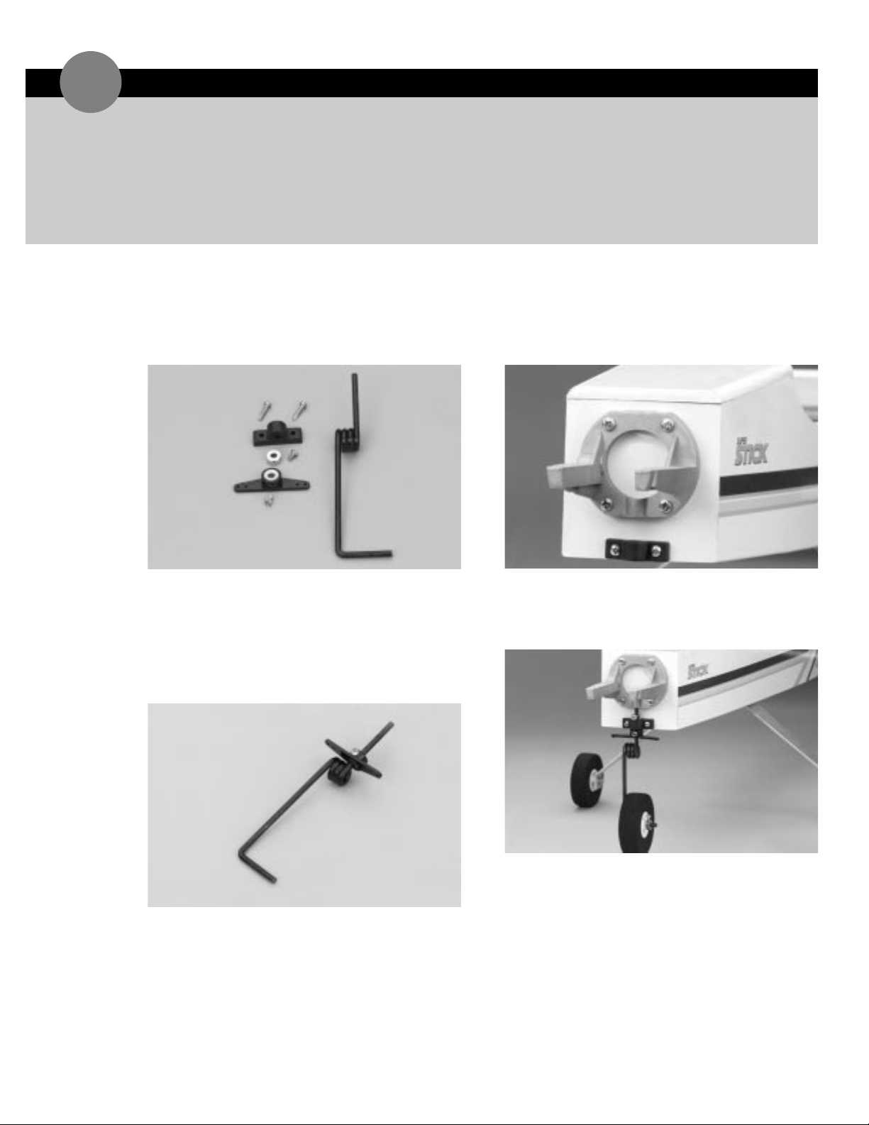
1. Locate the nose gear,nose gear control horn,nose
gear mount,one 5/32"wheel collar,and two 2.6mm
screws.
2. With the screw hole facing forward,slide the nose
gear control horn onto the straight end of the nose
gear so the control horn is situated in the flat spot on
the gear next to the coil.
➤ Note:If you do not have a flat spot on your landing
gear,you can easily make a flat spot using a Moto-tool.
3. Install the nose gear mount flush with the bottom of
firewall. Drill 1/16" holes and install wood screws.
➤ Important:Make sure the guide hole in the mounting
bracket is directly in line with the gear hole in the
engine mount.
4. Place a 5/32"wheel collar between the nose gear
mount and the motor mount. Insert the nose gear
assembly up through the nose gear mount until the
coil is just below the bottom of the fuselage.
5. Adjust the nose gear control horn until the arm is
parallel with the firewall. Apply Blue Locktite 242 to a
3mm screw and secure the steering arm in place.
6. Secure the remaining wheel collar using Blue Locktite
242 and a 3mm screw.
7. Install the front nose wheel using the supplied collar
and screw.
➤ Important:Be sure the nose wheel is aligned
perpendicular to the nose gear control horn as
shown.
INSTALLING THE NOSE GEAR
14
Page 26
➤ Parts Needed
Fuel tank
Fuel tubing
(no supplied)
Fuel klunk
Aluminum tube,short
(pickup)
Aluminum tube,long
(vent)
Silicone tubing
Rubber stopper
Long self tapping screw
Fuselage
➤ Tools & Adhesives Needed
Hobby knife
Phillips screwdriver
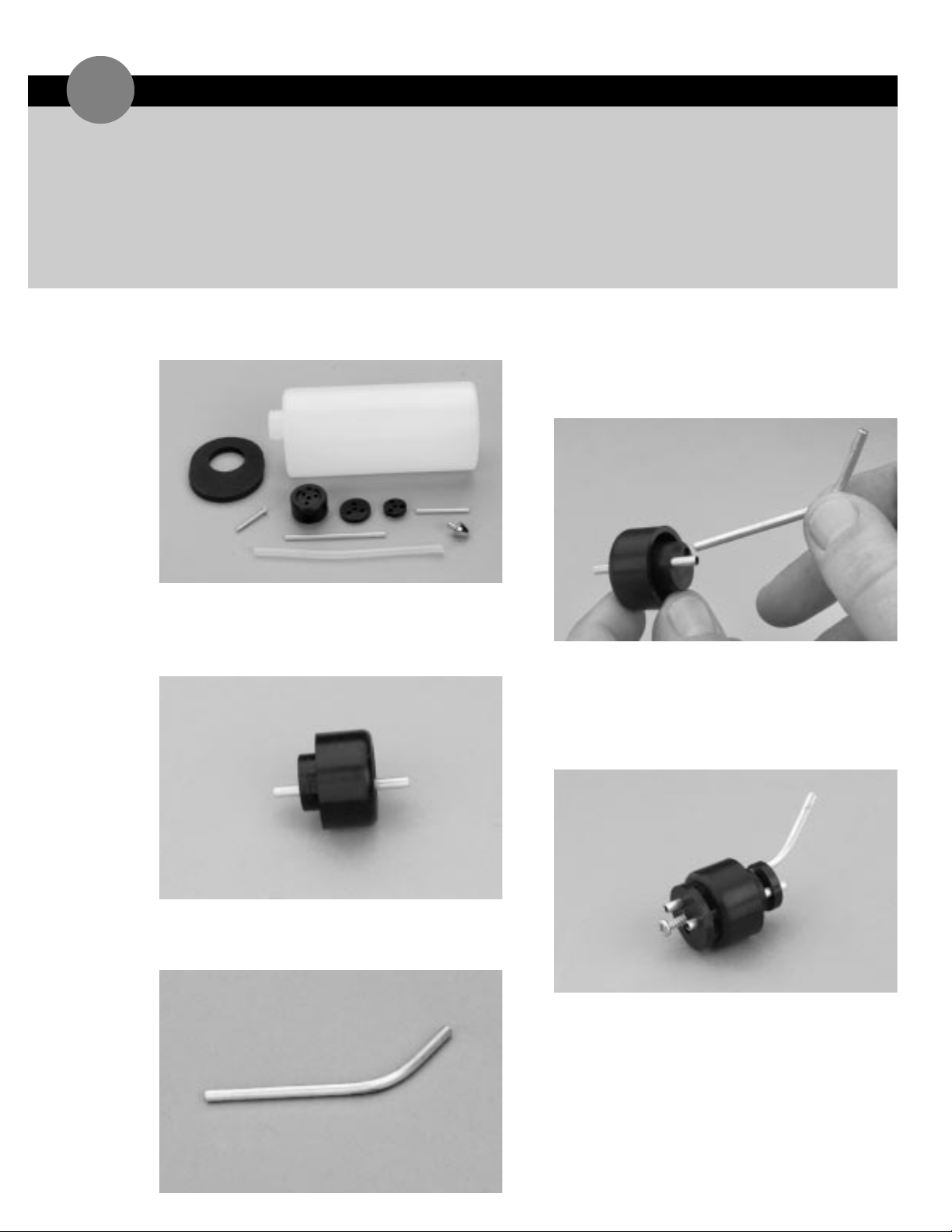
1. Locate the fuel tank and the fuel tank accessories.
2. Insert the short aluminum tube into one of the open
holes in the black rubber stopper so that an equal
amount of the tube extends from either side. This
tube will be used as the fuel tank pickup tube.
3. Locate the longer aluminum tube and bend it carefully
using your fingers as shown. This tube will be the fuel
tank vent tube.
4. Slide this tube into the remaining hole in the black
rubber stopper. It is easier if the tube is inserted
through the rear of the stopper, with the straight
portion first.
5. Slide the two plastic caps over the tubes as shown.
Note the orientation of the caps. The small inside cap
and the raised center face the black rubber stopper.
The large outside cap with the raised center face away
from the black rubber stopper. Insert the self tapping
screw into the end of cap and tighten slightly.
ASSEMBLING & INSTALLING THE FUEL TANK
15
Page 27
ASSEMBLING & INSTALLING THE FUEL TANK continued
15
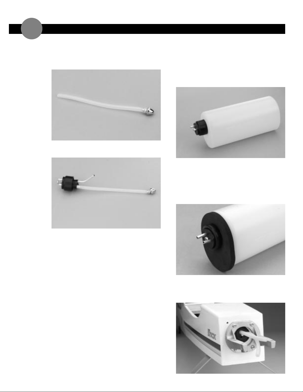
6. Locate the silicone fuel tubing and the metal fuel
klunk. Insert the fuel klunk into one end of the fuel
tubing. This assembly will be used for the fuel pickup
inside the fuel tank.
7. Install the open end of the fuel tubing on the shorter
aluminum tubing.
8. Carefully insert the assembly into the fuel tank and
press the fuel tank cap on firmly. Note the position of
the vent tube. To function properly the vent tube
must be positioned at the top of the tank.
➤ Note: It is important to ensure that the fuel tank
klunk does not touch the rear of the fuel tank. If it
does,simply cut a small portion off of the silicone fuel
tubing until the klunk no longer reaches the rear of
the tank.
9. It is important to note that the stopper is mounted
closer to one edge of the fuel tank than the other.
This “closer edge” is the top of the fuel tank.
➤ Important: Remember which tube is the fuel tank
pickup and which is the vent so you will properly
connect fuel lines to the engine.
10. Cut away the covering in the center of the firewall in
the middle of the engine mount.
11. Place the foam fuel tank collar around the neck of the
fuel tank and press the fuel tank into the fuselage
firmly against the firewall.
12. Place the tank into the fuselage and press it into
position until the stopper on the tank inserts into the
hole in the firewall. Connect 5" pieces of fuel line to
the installed tank.
Page 28
➤ Parts Needed
Fuselage
Plywood servo tray
3 servos
➤ Tools & Adhesives Needed
Hobby knife or round file
6-minute epoxy
Epoxy brush
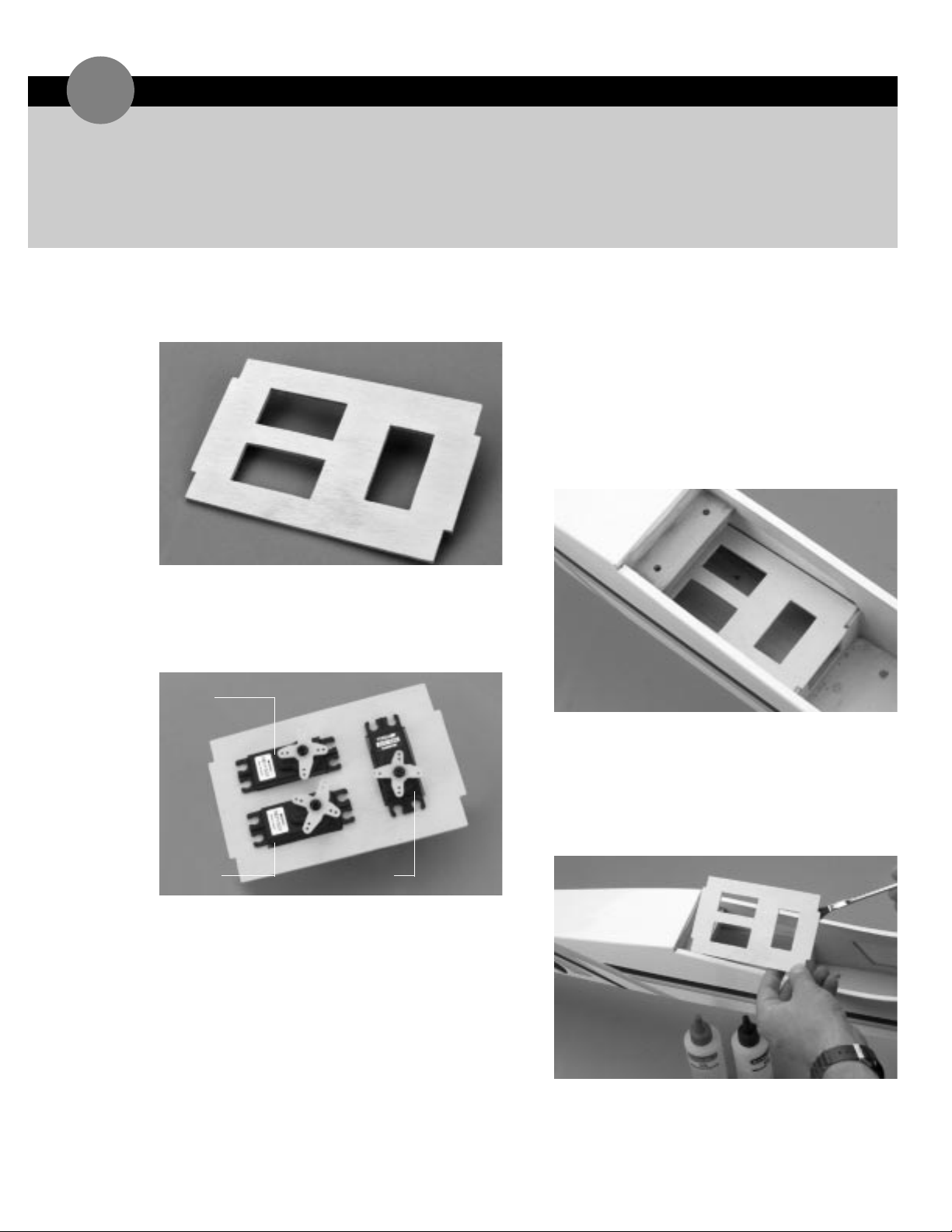
1. Remove the plywood servo tray from the die-cut
plywood sheet.
2. Trial fit the throttle, elevator and rudder servos in the
servo tray. Depending upon the servos utilized,it may
be necessary to enlarge the openings in the tray
slightly. To do so,use a file or sharp hobby knife
accordingly.
3. After the proper servo fit has been achieved,remove
the three servos from the servo tray. Trial fit the
servo tray into the fuselage,noting the correct
orientation. The single servo cut-out should be
closest to the front of the fuselage.
➤ Note:The tray should seat snugly into the notches in
the servo tray support and fuselage former. If it
doesn’t,remove a small portion of the tab from the
servo tray using a file or sharp hobby knife.
4. Mix a small amount,approximately 1/8 ounce,of
6-minute epoxy. Using an epoxy brush,apply epoxy to
the servo tray in the areas that will come in contact
with the servo tray support and the fuselage sides.
Install the servo tray into the fuselage,noting the
correct orientation as described in Step 3 of this
section.
INSTALLING THE SERVO TRAY
16
rudder
rudder
elevator
elevator
throttle
throttle
Page 29
➤ Parts Needed
Engine
Engine mounting bracket (2)
Engine mounting screws and nuts (4 each)
Fuselage
➤ Tools & Adhesives Needed
Phillips screwdriver
Blue Locktite 242
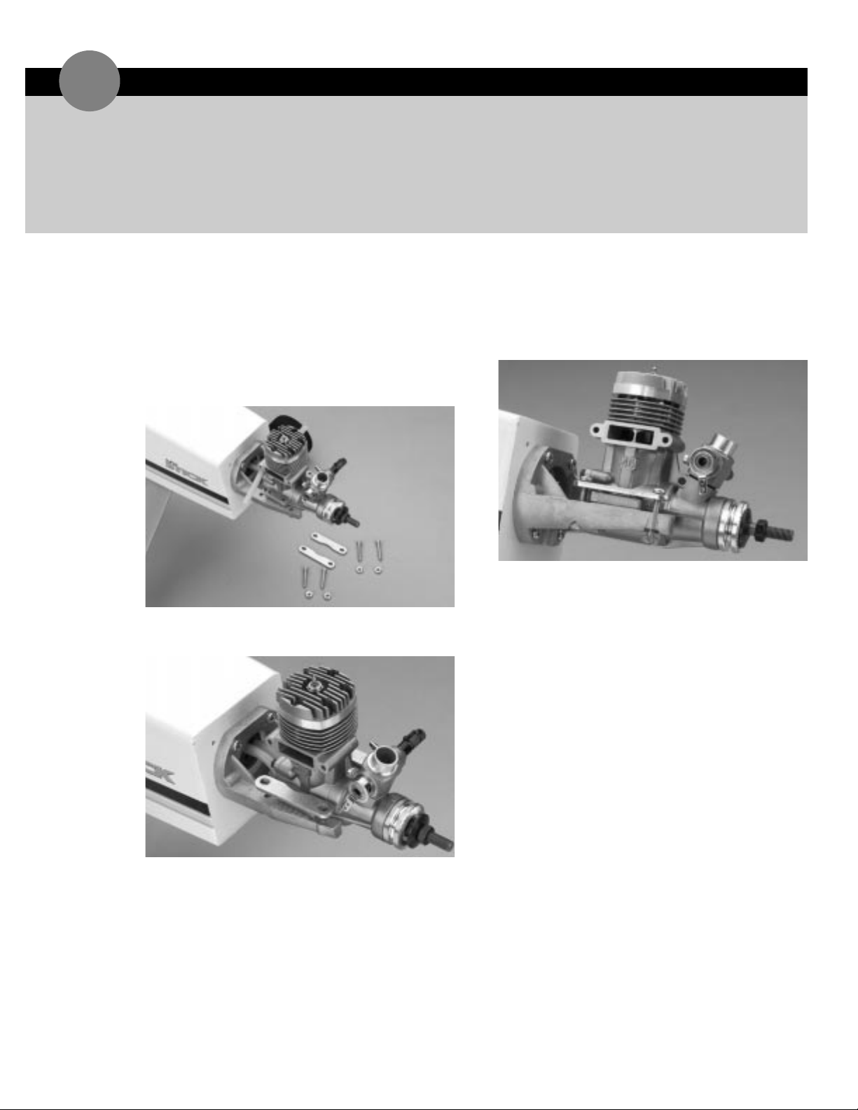
1. Remove the two engine mounting brackets,four
4 x 20mm screws and four 4mm nuts from the
hardware bag.
2. Position the engine on the motor mount so the
center line of the engine is in line with the center line
of the fuselage.
3. Place one engine mounting bracket,across each of the
engine mounting lugs as shown.
4. Insert one 4 x 20mm screw into each of the engine
mounting bracket holes. Press one of the 4mm nuts
into the corresponding receptacle on the bottom of
the motor mount. Apply Blue Locktite 242 to secure
the nut in place and firmly tighten the screw.
5. Install the fuel tube from the fuel tank pickup line to
the carburetor fuel nipple. The vent line will be
installed onto the pressure nipple after the muffler is
installed.
➤ Hint: Do not install the muffler to the engine until
after the throttle linkage is installed.
INSTALLING THE ENGINE
17
Page 30
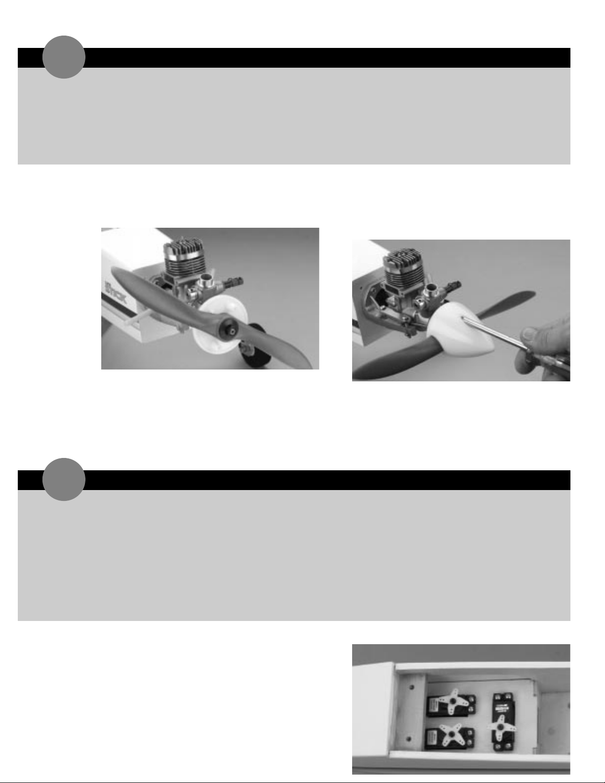
1. Remove the propeller nut and prop washer from the
engine. Install the spinner backplate on the crankshaft,
as shown.
2. Place the propeller onto the crankshaft so it seats
correctly against the spinner backplate. Next, install
the washer and the prop nut onto the crankshaft and
tighten securely.
3. Attach the spinner to the spinner backplate using the
two screws provided in the hardware bag.
➤ Note: Be sure not to over-tighten the spinner screws
as doing so would damage the spinner screws.
1. Install the rubber grommets and eyelets in the three
remaining servos. Position the servos in the fuselage
servo tray as shown,noting the location of the output
horns. Screw the servos in place using 12 servo
screws,which are included with the servos.
➤ Parts Needed
Spinner
Spinner backplate
Spinner screws (2)
Fuselage
➤ Tools & Adhesives Needed
Phillips screwdriver
➤ Parts Needed
4-channel radio system with 3 servos
and hardware (not included)
Fuselage
Radio packing foam (not included)
Antenna tube (optional,not included)
Y-harness (optional, must have if using a
4-channel radio)
➤ Tools & Adhesives Needed
Phillips screwdriver
Hobby knife
Drill
Drill bit:1/16
"
INSTALLING THE RADIO SYSTEM
19
INSTALLING THE SPINNER
18
Page 31
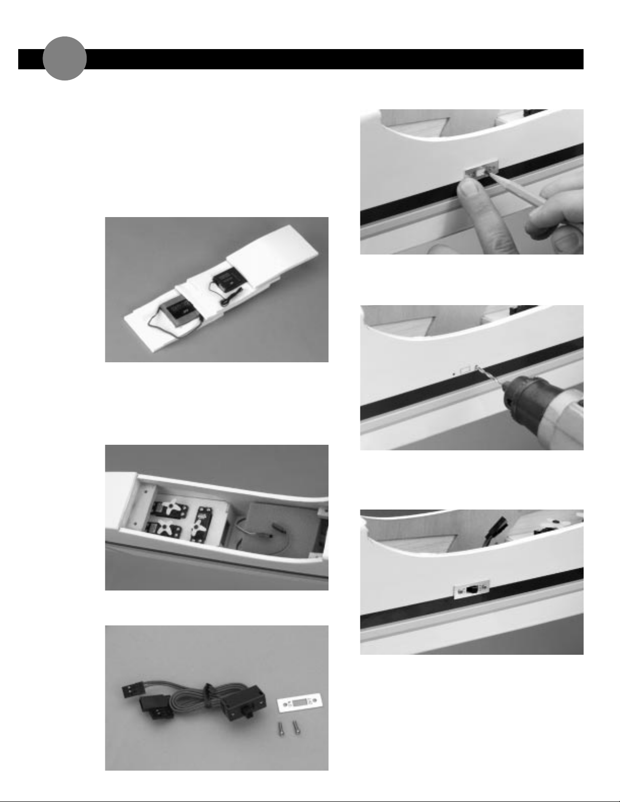
2. Use radio packing foam (available at your local hobby
dealer) when you install the receiver and battery.
With a sharp hobby knife,cut a solid layer of foam the
size of the compartment that is in front of the servo
tray. Cut out another layer of foam that is identical in
size,however, cut an opening in the center of this
foam so it will accept the receiver battery pack. Place
another solid layer of foam on top of this layer. Cut
another layer of foam to accept the receiver. The final
layer of foam should be solid.
3. Place the layers of foam with the battery and receiver
in their respective locations in the front compartment
of the fuselage as shown. Route the antenna back
through the fuselage using an antenna tube (not
included) or route it outside the fuselage back to the
vertical stabilizer.
4. The switch should be mounted on the left side of the
fuselage,away from the exhaust.
➤ Hint: Remove the switch plate to use as a template.
5. Drill the two mounting holes as marked using a 1/16
"
drill bit. Using your hobby knife,carefully cut out for
the receiver switch between the screw holes.
6. Reposition the switch plate as shown and place the
switch on the inside of the fuselage. Using the two
screws supplied with the switch,attach the switch to
the fuselage.
INSTALLING THE RADIO SYSTEM continued
19
Page 32
➤ Parts Needed
Wing
Heat shrink tubing
Clevises
Threaded rods
➤ Tools & Adhesives Needed
Z-bend pliers
Felt tipped pen
Thick CA glue
Hobby knife
Heat gun
Wire cutters
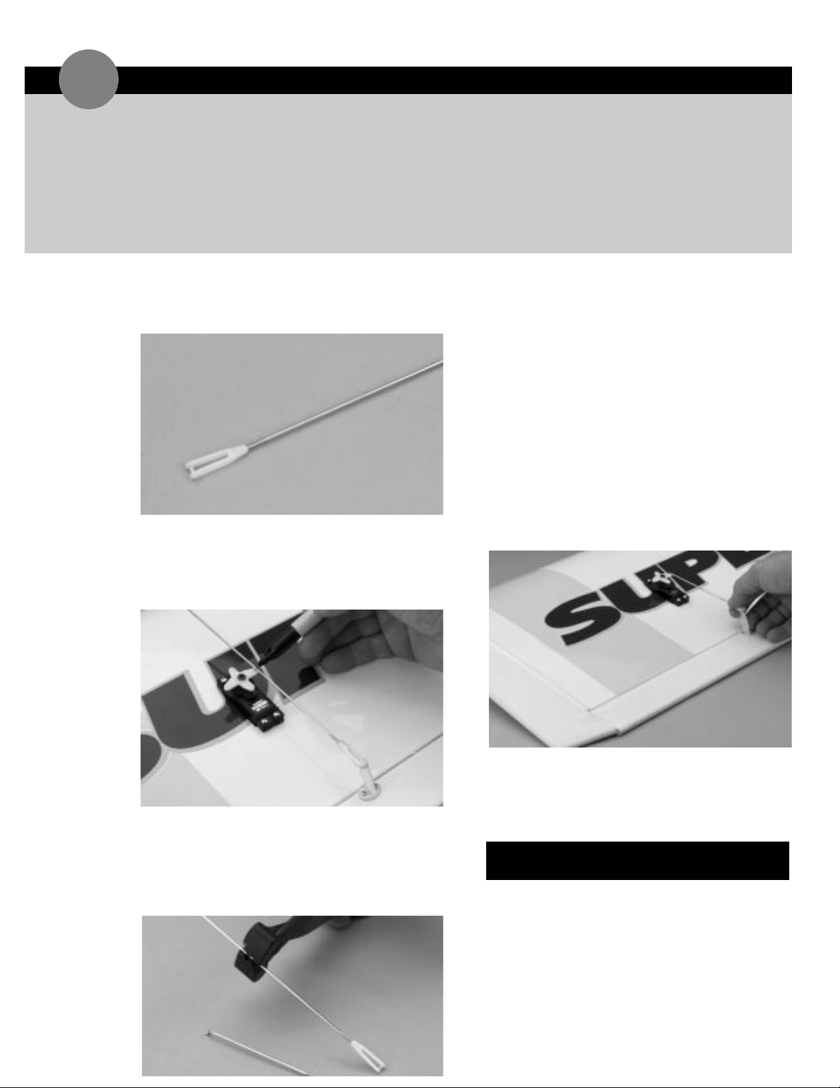
1. Locate two of the threaded rods. Thread a clevis at
least 20 turns,onto each rod. Be sure they are not
the longer rods.
2. Install the clevis with the attached linkage to the
aileron control horn. Center the servo horn as
shown and,using a felt tipped pen,make a mark on
the linkage where the Z-bend will be inserted into the
horn.
3. Make a Z-bend in the linkage and cut off the excess
linkage.
➤ Important: Do not discard the piece of linkage you
just cut off;this will be used to make the rudder and
elevator pushrods.
4. Center the servo horn and install the Z-bend into the
outer-most hole of a standard size.
5. Attach the linkages onto their respective aileron
horns.
➤ Note: It is a good idea to place a piece of fuel tubing
over the clevises as shown. This will provide extra
insurance against the clevises accidentally coming
open.
6. With the servo arm centered as shown,adjust the
aileron linkage until the aileron is exactly in the
neutral position. Follow this procedure for both
aileron linkages.
INSTALLING THE AILERON LINKAGES
2
0
2 Long threaded rods (throttle, nose gear)
5 Threaded rods (ailerons, rudder, elevator)
2 Wooden dowels (pushrods)
2 Heat shrink tubing
1 Control horn/clevis parts tree
TOTAL PUSHROD & ACCESSORIES
LIST FOR SUPER STICK
Page 33
➤ Parts Needed
Fuselage
2 threaded rods
2 rods cut off from aileron linkage (Section 20)
Heat shrink tubing
Clevis
Z-bend pliers
Felt tipped pen
Thick CA glue
Hobby knife
Heat gun
Wire cutters
Ruler
Masking tape
➤ Tools & Adhesives Needed
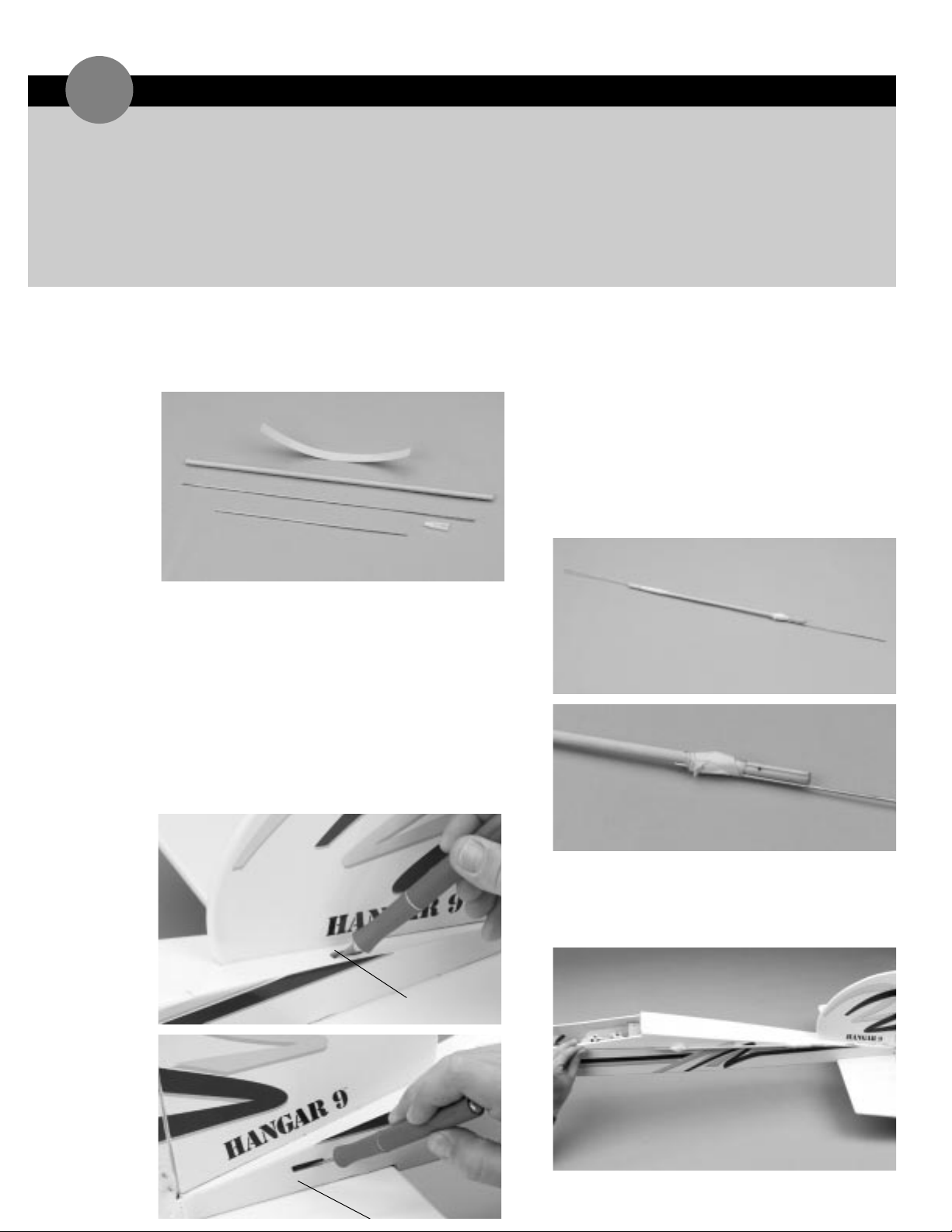
1. Locate one of the threaded rods,one piece of the
extra rod from Section 20,one piece of the yellow
heat shrink tubing,one clevis and one of the balsa
pushrod dowels.
2. Cut the heat shrink into two equal pieces with a
sharp hobby knife or a pair of scissors.
3. Carefully cut away the covering on the top left side of
the fuselage next to the vertical fin for the rudder and
the right side for the elevator — this is where the
pushrods will exit.
➤ Note: If the fuselage does not have a pre-cut slots
under the covering for the pushrods to exit from,
carefully cut a notch in the fuselage as shown.
4. To determine the approximate length of the pushrods,
temporarily tape a rod (using masking tape) with the a
threaded end,half the distance of the rod,onto the
wooden dowel. Then take the piece of rod you cut
off the aileron linkage and tape it onto the other end
of the wooden dowel. Make sure you position the
rod past the pre-drilled hole in the wooden dowel.
➤ Hint: Do not put any tape around the rod and dowel
where the pre-drilled hole is located in the wooden
dowel as you are going to need to make a mark on
the rod.
5. Thread a clevis at least 12 turns onto the threaded
rod. Position the temporarily assembled pushrod
along the outside of the fuselage,lining it up with the
control horn and extending it over the servos.
ASSEMBLING ELEVATOR & RUDDER PUSHRODS
2
1
rudder
Page 34
ASSEMBLING ELEVATOR & RUDDER PUSHRODS continued
2
1
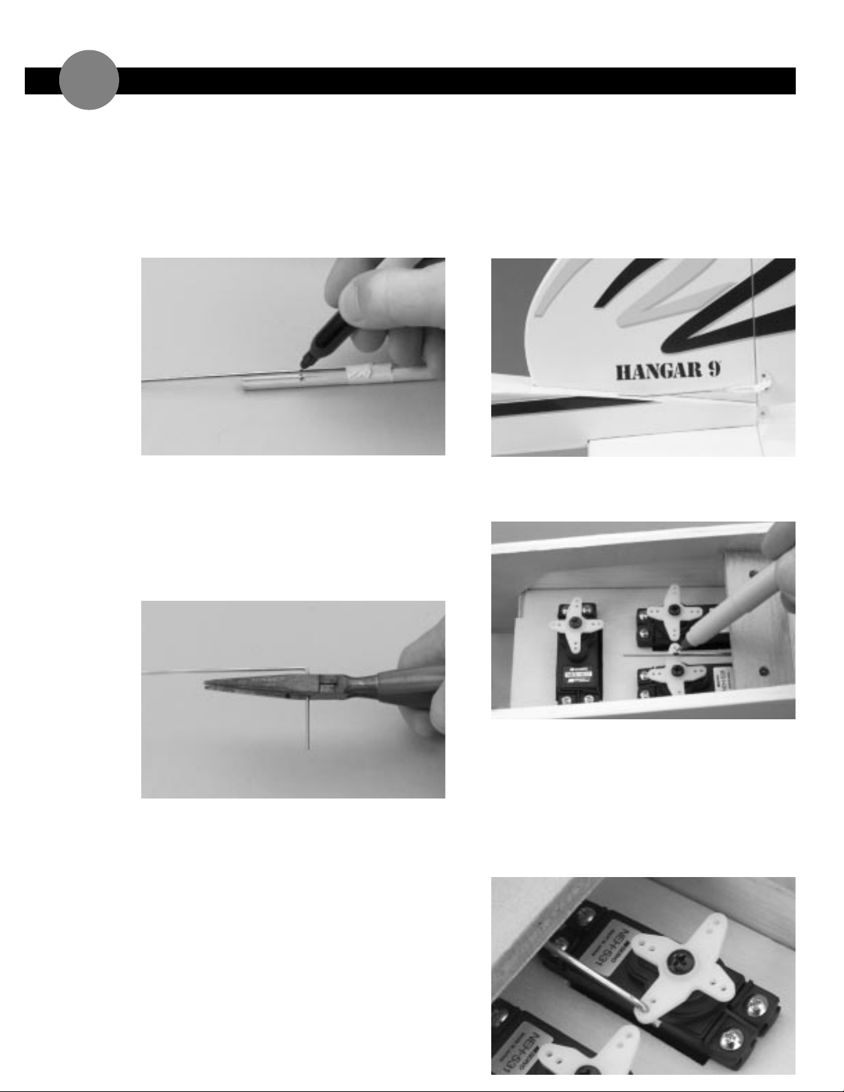
6. Adjust the rods on the wooden dowel if necessary to
allow for a Z-bend to be made in the non-threaded
rod that will be attached to the servo.
7. Mark the non-threaded rod where the Z-bend will be
located. Also mark the rods where the pre-drilled
holes are located in the dowel.
8. Dissemble the pushrod and remove the clevis. Make a
90 degree bend on the non-threaded rod at the mark
where the pre-drilled hole is located on the wooden
dowel. Leave a 1/4"of rod after the 90 degree bend
and cut off any excess. Make a 90 degree bend in the
threaded rod at the mark of the pre-drilled hole of
the wooden dowel and leave a 1/4"of rod after the
bend.
9. Insert the 90 degree bend into the hole of the balsa
dowel and saturate the balsa with thick CA glue
where the rod contacts the balsa.
10. Slide a piece of heat shrink tubing over each end of
the balsa dowel and shrink it in place using a heat gun.
11. Insert the pushrod assembly,threaded rod first,into
the fuselage so the threaded rod exits the rudder
pushrod hole. Screw on a clevis 20 complete turns.
Fasten the clevis to the rudder control horn.
➤ Note: It is a good idea to place a piece of fuel tubing
over the clevis (as shown) as extra insurance to
prevent the clevis from accidentally coming open.
12. Center the rudder and elevator servo,and using a felt
tipped pen,place a mark on the end of the pushrod
where it passes the connection hole of servo horn.
13. Using Z-bend pliers, make a Z-bend at the marked
location on the rod. Cut off the excess rod past the
Z-bend.
14. Insert the Z-bend into the servo arm.
➤ Hint: It may be necessary to remove the servo arm
to insert the Z-bend.
Page 35
➤ Parts Needed
1 Long threaded rod
1 Clevis
Fuselage
➤ Tools & Adhesives Needed
Z-bend pliers
Wire cutters
Felt tipped pen
INSTALLING THE THROTTLE LINKAGE
2
2
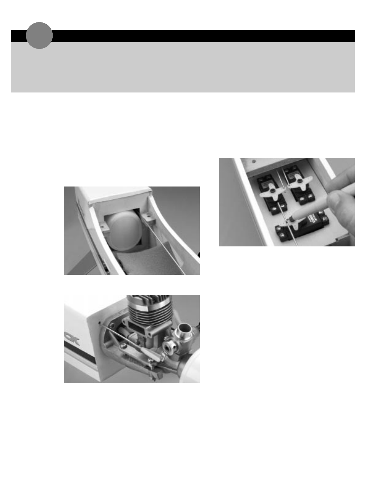
1. Locate one of the longer threaded rods and one
clevis.
2. Screw the clevis onto the threaded end of the rod
approximately 20 turns.
3. Insert the threaded rod,unthreaded end first,through
the 1/16”throttle linkage hole in the firewall. The
rod should exit through the radio tray compartment.
4. Attach the clevis to the throttle lever of the
carburetor, opening the carburetor half way.
5. Center the throttle servo. Using a felt tipped pen,
mark the rod where it passes the respective servo
arm.
➤ Note: It is important to be sure that the carburetor
remains half open when the throttle servo is
centered.
6. Using Z-bend pliers,make a Z-bend at the marked
spot on the rod. Cut-off the excess rod. Remove
throttle servo arm and insert Z-bend into servo arm.
Page 36
➤ Parts Needed
Fuselage
Long threaded rod
Clevis
➤ Tools & Adhesives Needed
Z-bend pliers
Wire cutters
Felt tipped pen
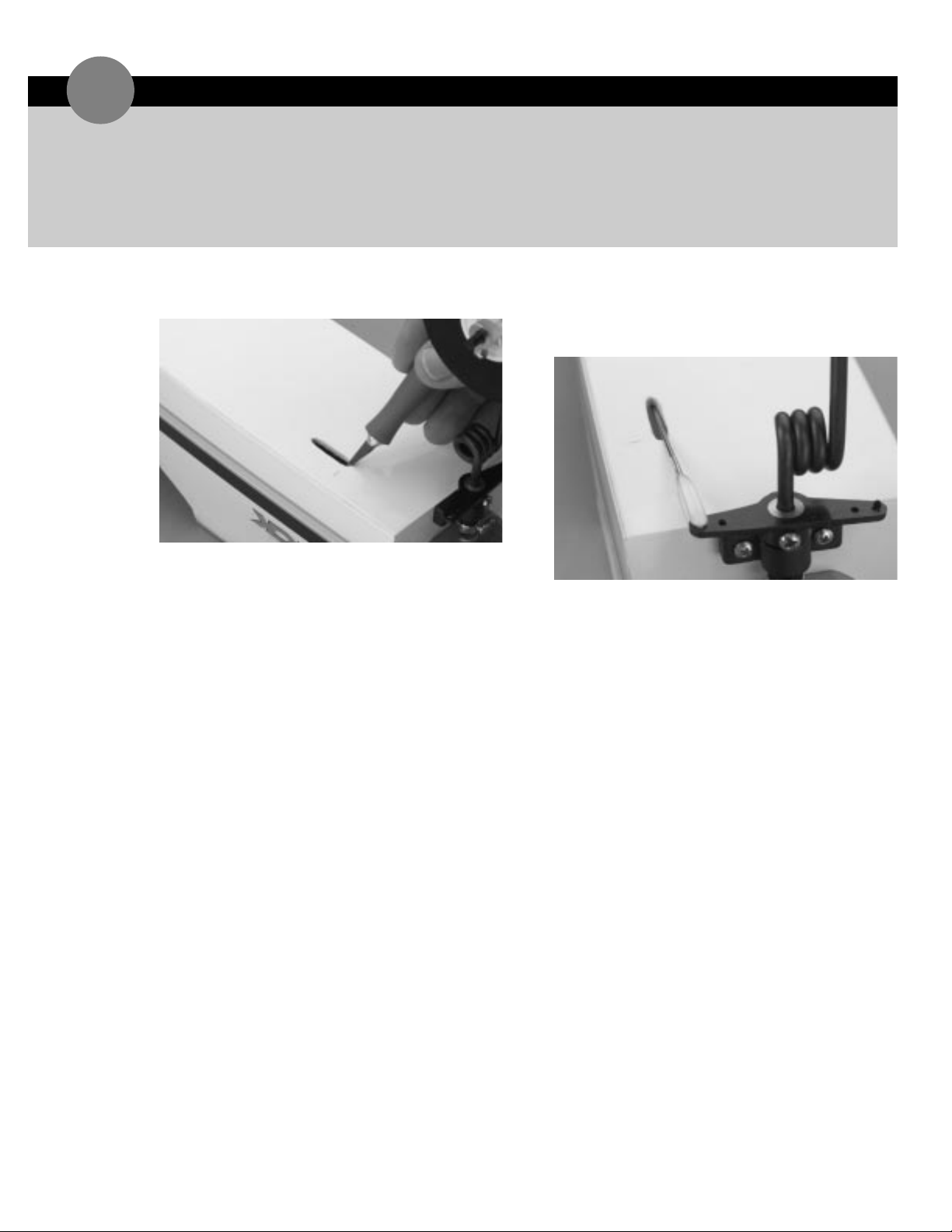
1. Locate the remaining long threaded rod and clevis.
2. Carefully cut away the covering on the bottom of the
fuselage where the pushrod will exit,if not already
done.
3. Insert the threaded rod,threaded end first,through
the nose wheel linkage slot and into its respective
1/16"guidance holes in the fuselage.
4. Screw on a clevis 20 full turns. Fasten the clevis in the
outermost servo arm hole opposite of the rudder
servo Z-bend.
5. Be sure that the rudder servo is centered. Using a felt
tipped pen,place a mark on the unthreaded end of
the pushrod where it passes the respective servo arm.
6. Using Z-bend pliers,make a Z-bend at the marked
location on the rod. Cut off the excess rod.
7. Insert the Z-bend into the hole on the servo control
arm. It may be necessary to remove the control arm
during installation of the Z-bend.
INSTALLING THE NOSE WHEEL LINKAGE
23
Page 37
CONTROL THROW RECOMMENDATION
24
BALANCING THE SUPER STICK
25
The following control throws offer the most positive
response and are a good place to begin. After you’ve
become more familiar with the flight characteristics,
adjust the control throws to meet your style of flying.
An important part of preparing the aircraft for flight is
properly balancing the model. Don’t inadvertently
neglect this step. The recommended C.G.(Center of
Gravity) location for the first flights with the Super
Stick is 1/8" behind the main spar of the wing (the
main spar spans the length of the wing underneath the
back edge of the wing sheating).
If necessary,add weight to either the tail or nose until
the correct balance is achieved. Stick-on weights are
available at your local hobby shop and work well for
this purpose.
➤ Normal Rate
Aileron: 5/16"up,5/16"down
Elevator: 3/8"up,3/8"down
Rudder: 7/8"right,7/8"left
➤ High Rate
Aileron: 1/2"up,1/2"down
Elevator: 1/2"up,1/2"down
Rudder: 1-3/8"right,1-3/8"left
➤ Normal Rate
Aileron: 3/8"up,3/8"down
Elevator: 3/8"up,3/8"down
Rudder: 1"right,1"left
➤ High Rate
Aileron: 5/8"up,5/8"down
Elevator: 5/8"up,5/8"down
Rudder: 1-5/8"right,1-5/8"left
SUPER STICK 40 SUPER STICK 60
Page 38
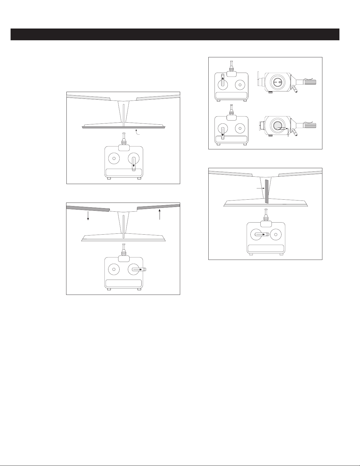
1. Check that all control functions move in the correct
direction. If not, use the respective reversing switch
to correct the direction.
➤ Note: Mode II transmitter shown in diagrams.
2. Check that each clevis is securely snapped into
position.
3. Check that all servo horn screws are tight.
4. Charge the transmitter and receiver battery per the
instructions included with the radio system.
5. Read and follow all the instructions included with the
engine and follow the recommended break-in
procedure.
ELEVATOR
ELEVATOR
PRE-FLIGHT CHECK
CARBURETOR
1/16”
THROTTLE
RUDDER
AILERON
AILERON
AILERON
RUDDER
Page 39

PRE-FLIGHT AT THE
FLYING
FIELD
Range T est Y our Radio
1. Before each flying session be sure to range check your
radio. This is accomplished by turning on your
transmitter with the antenna collapsed. Turn on the
radio in your airplane. With your airplane on the
ground,you should be able to walk 30 paces away
from your airplane and still have complete control of
all functions. If not,don't attempt to fly! Have your
radio equipment checked out by the manufacturer.
2.
Double check that all controls (aileron,elevator,
throttle,
rudder) move in the correct direction.
3. Be sure that your batteries are fully charged per the
instructions included with your radio.
Adjusting the Engine
1. Completely read the instructions included with your
engine and follow the recommended break-in
procedure. At the field adjust the engine to a slightly
rich setting at full throttle and adjust the idle and low
speed needle so that a consistent idle is achieved.
Before you fly be sure that your engine reliably idles,
transitions and runs at all throttle settings . Only
when this is achieved should any plane be considered
ready for flight.
Page 40

AMA SAFETY CODE
1994 Official AMA
National Model Aircraft Safety Code
Effective January 1,1994
Model flying must be in accordance with this Code
in order for AMA liability protection to apply
General
1. I will not fly my model aircraft in sanctioned events,air shows,
or model flying demonstrations until it has been proven to be
airworthy by having been previously,successfully flight tested.
2. I will not fly my model higher than approximately 400 feet
within 3 miles of an airport without notifying the airport
operator. I will give right-of-way and avoid flying in the
proximity of full-scale aircraft. Where necessary,an observer
shall be utilized to supervise flying to avoid having models fly in
the proximity of full-scale aircraft.
3. Where established,I will abide by the safety rules for the flying
site I use,and I will not willfully and deliberately fly my models
in a careless,reckless and/or dangerous manner.
4. At all flying sites a straight or curved line(s) must be established
in front of which all flying takes place with the other side for
spectators. Only those persons essential to the flight
operations are to be permitted on the flying side of the line;all
others must be on the spectator side. Flying over the spectator
side of the line is prohibited,unless beyond the control of the
pilot(s). In any case,the maximum permissible takeoff weight of
the model is 55 pounds unless as stated in their official rules.
5. At air shows or model flying demonstrations a single straight
line must be established,one side of which is for flying, with the
other side for spectators. Only those persons accredited by
the contest director or other appropriate official as necessary
for flight operations or as having duties or functions relating to
the conduct of the show or demonstration are to be permitted
on the flying side of the line. The only exceptions which my be
permitted to the single straight line requirements,under special
circumstances involving consideration of side conditions and
model size,weight,speed, and power,must be jointly approved
by the AMA President and the Executive Director.
6. Under all circumstances,if my model weighs over 20 pounds,I
will fly it in accordance with paragraph 5 of this section of the
AMA Safety Code.
7. I will not fly my model unless it is identified with my name and
address or AMA number,on or in the model. Note:This does
not apply to models flown indoors.
8. I will not operate models with metal-bladed propellers or with
gaseous boosts,in which gases other than air enter their
internal combustion engine(s);nor will I operate models with
extremely hazardous fuels such as those containing
tetranitromethane or hydrazine.
9. I will not operate models with pyrotechnics (any device that
explodes,burns,or propels a projectile of any kind) including,
but not limited to,rockets,explosive bombs dropped from
models,smoke bombs,all explosive gases (such as hydrogenfilled balloons),ground mounted devices launching a projectile.
The only exceptions permitted are rockets flown in accordance
with the National Model Rocketry Safety Code or those
permanently attached (as per JATO use);also those items
authorized for Air Show Team use as defined by AST Advisory
Committee (document available from AMA HQ). In any case,
models using rocket motors as primary means of propulsion
are limited to a maximum weight of 3.3 pounds and a G series
motor. Note:A model aircraft is defined as an aircraft with or
without engine,not able to carry a human being.
10. I will not operate any turbo jet engine (axial or centrifugal flow)
unless I have obtained a special waiver for such specific
operations from the AMA President and Executive Director and
I will abide by any restriction(s) imposed for such operation by
them. (Note:This does not apply to ducted fan models using
piston engines or electric motors.)
11. I will not consume alcoholic beverages prior to,nor during,
participation in any model operations.
Radio Control
1. I will have completed a successful radio equipment ground
range check before the first flight of a new or repaired model.
2. I will not fly my model aircraft in the presence of spectators
until I become a qualified flier, unless assisted by an experienced
helper.
3. I will perform my initial turn after takeoff away from the pit or
spectator areas,and I will not thereafter fly over pit or
spectator areas,unless beyond my control.
4. I will operate my model using only radio control frequencies
currently allowed by the Federal Communications Commission.
(Only properly licensed Amateurs are authorized to operate
equipment on Amateur Band frequencies.) Further,any
transmitters that I use at a sanctioned event must have a
certified R/CMA-AMA gold sticker affixed indicating that it was
manufactured or modified for operation at 20 kHz frequency
separation (except 27 MHz and 53 MHz).
5. I will not knowingly operate an R/C system within 3 miles of a
pre-existing model club flying site without a frequency sharing
agreement with that club.
 Loading...