

Page 1
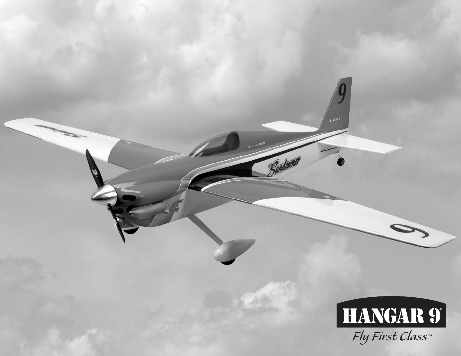
Sundowner 36 ARF
Assembly Manual
Page 2
Notice
All instructions, warranties and other collateral
documents are subject to change at the sole discretion
of Horizon Hobby, Inc. For up-to-date product
literature, visit http://www.horizonhobby.com and click
on the support tab for this product.
Meaning of Special Language
The following terms are used throughout the product
literature to indicate various levels of potential harm
when operating this product:
NOTICE: Procedures, which if not properly followed,
create a possibility of physical property damage AND a
little or no possibility of injury.
CAUTION: Procedures, which if not properly followed,
create the probability of physical property damage AND a
possibility of serious injury.
WARNING: Procedures, which if not properly followed,
create the probability of property damage, collateral
damage, and serious injury OR create a high probability
of superficial injury.
WARNING: Read the ENTIRE instruction manual to
become familiar with the features of the product before
operating. Failure to operate the product correctly can result
in damage to the product, personal property and cause
serious injury.
This is a sophisticated hobby product and NOT a toy. It must
be operated with caution and common sense and requires
some basic mechanical ability. Failure to operate this Product
in a safe and responsible manner could result in injury or
damage to the product or other property. This product is not
intended for use by children without direct adult supervision.
Do not attempt disassembly, use with incompatible
components or augment product in any way without the
approval of Horizon Hobby, Inc. This manual contains
instructions for safety, operation and maintenance. It is
essential to read and follow all the instructions and warnings
in the manual, prior to assembly, setup or use, in order to
operate correctly and avoid damage or serious injury.
Table of Contents
Intro ..................................................................................2
Product Support ...............................................................2
Specifications ....................................................................2
Included Parts Listing .......................................................3
Contents of Kit and Parts Listing ......................................4
Safety Precautions and Warnings .....................................4
Important Information Regarding Warranty ......................5
Using the Manual ..............................................................5
UltraCote® Covering Colors .............................................5
Recommended Power Setups ...........................................5
Transmitter Requirements.................................................5
Radio Equipment Requirements .......................................5
Optional Accessories ........................................................5
Field Equipment Required .................................................5
Optional Field Equipment ..................................................5
Required Tools ..................................................................6
Required Adhesives ..........................................................6
Before Starting Assembly .................................................6
Elevator and Stabilizer Installation ....................................6
Rudder, Fin and Tail Wheel Installation ...........................10
Rudder and Elevator Linkage Installation ........................14
Main Landing Gear Installation .......................................18
Hinging the Aileron .........................................................20
Aileron Servo Installation ................................................21
Aileron Linkage Installation .............................................25
Engine Installation ..........................................................27
Throttle Servo and Linkage Installation ..........................29
Fuel Tank Installation ......................................................32
Cowling and Muffler Installation - Glow Option ..............34
Receiver, Receiver Battery and
Switch Harness Installation - Glow Option ..............36
Motor Installation ............................................................37
Cowling, Propeller and Spinner Installation - EP Option . 39
Receiver and Motor Battery Installation - EP Option ......40
Final Assembly ................................................................41
Center of Gravity .............................................................43
Control Throws ...............................................................43
Preflight ..........................................................................44
Range Test Your Radio ...................................................44
Flight Hints and Tips .......................................................44
Safety Do’s and Don’ts for Pilots ....................................45
Daily Flight Checks ..........................................................45
Warranty and Repair Policy ............................................45
Warranty Services ...........................................................46
Compliance Information for the European Union ............46
Academy of Model Aeronautics
National Model Aircraft Safety Code ........................47
Intro
The Sundowner 36 is a speedy sport-scale perfect for
high-speed aerobatics and club racing. Based on the
Sundowner Formula 1, this speedy performer has a scaleddown aggressive racer body design at home equally as a
sport flyer or as a serious racer. Designed to be powered
by EP or GP power systems, this plane delivers racer
styling at a lower cost to you. This spirited speedster is
constructed of lightweight balsa and plywood with carbon
fiber reinforcements for added strength and durability.
The low parts count makes this ARF exceptionally easy to
assemble, and with a two piece wing, easy to disassemble
for transport. The one-piece fiberglass cowl has hidden cowl
screws, adding to its great looks. The internals are easily
accessed through the removable canopy, which is held
securely in place with tabs and magnets. The Sundowner
can be powered for sport utilizing the E-flite Power 32
motor or the Evolution .40NX glow engine. Because of its
smooth flight characteristics and precise, sport handling,
even intermediate pilots will feel comfortable behind the
sticks. Unlike other racers that may be difficult to fly, the
Sundowner 36’s streamlined design makes this racer
smooth, precise and ready-to-roll.
Product Support
For technical assistance with this product, please contact the
appropriate Horizon Product Support office. This information
is located in the back of this manual.
Specications
Wingspan 51.5 in (131cm)
Length 44.0 in (114cm)
Wing Area 400 sq in (25.8 sq dm)
Weight 4.00–4.50 lb (1.8–2.0 kg)
Engine .32–.36 2-stroke glow
Motor Size Power 25 or Power 32 brushless
Radio 4-channel minimum
Servos 5 mini servos (4 with EP setup)
2 Hangar 9 Sundowner 36 ARF
Page 3

Included Parts Listing
PACKAGED INDIVIDUALLY LARGE BAGS
Fuselage with canopy hatch
Left wing with aileron
Right wing with aileron
Tail set
Landing gear
Wheel pants (right and left)
Cowl
Carbon wing tube
Spinner
Landing gear cover plate
FUSELAGE
Main wheel, 2-inch (51mm) (2)
Nylon clevis (2) rudder and elevator
Pushrod connector (with 3mm x 4mm machine screw) (1) throttle pushrod at servo
1.5mm knurled nut (1) throttle pushrod at servo
1.5mm washer (1) throttle pushrod at servo
Tail gear wire with wheel collar and setscrew (1)
Tail wheel bracket (1)
Tail wheel, 1-inch (25mm) (1)
Wheel collar with setscrew, 1.5mm (1) tail wheel retention
Wheel collar, 4mm with setscrew (2) main wheel retention
Axles, 4mm (2) main gear axles
Threaded control horn (2) rudder and elevator horns
Control horn backplate (2) rudder and elevator horns
Control horn fitting (2) rudder and elevator horns
2mm x 12mm machine screw (4) aileron control horns
2mm x 12mm machine screw (6) rudder and elevator control
horns
2mm x 8mm self-tapping screw (2) tail wheel bracket attachment
to fuselage
2mm x 8mm self-tapping screw (8) aileron servo hatches
2.5mm x 10mm machine screw (2) wheel pant attachment
HARDWARE
3
2mm x 8
/4-inch (220mm) pushrod tube (1) throttle
2mm x 137/8-inch (352mm) throttle pushrod (1) throttle
2mm x 201/4-inch (514mm) pushrod (1) elevator
2mm x 217/8-inch (555mm) pushrod (1) rudder
2-inch (51mm) pushrod (2) (1) aileron
3mm blind nut (4) engine mount to fuselage
3mm lock washer (4) engine mount to fuselage
3mm locknut (4) engine to mount, or EP motor
to standoffs
3mm washer (12) engine to mount and mount
to fuselage, or EP motor to
standoffs
3mm washer (2) cowl mounting
3mm washer (2) wing retention
3mm x 10mm socket head screw (2) cowl mount
3mm x 10mm socket head screw (2) wing retention
3mm x 20mm socket head screw (4) engine mount to fuselage
3mm x 25mm socket head screw (4) engine to mount
3mm x 30mm socket head screw (4) motor mount (Power 25)
3mm x 35mm socket head screw (4) motor mount (Power 32)
3mm x 4mm socket head screw (1) throttle pushrod to servo
4mm washer (2) landing gear to fuselage
4mm x 12mm socket head bolt (2) landing gear to fuselage
Locknut, 4mm (2) axle to landing gear
Aileron servo cover (2)
1
Aluminum stand-off, 1
/16-inch (27mm) (4) power 32 to firewall
Aluminum stand-off, 3/4-inch (22mm) (4) power 25 to firewall
WING
5/16 x 5/16 x 5/8-inch (8mm x 8mm x 15mm) hardwood aileron servo mounting block (4)
Nylon clevis (2) aileron clevises
Control horn (2) aileron horns
Control horn backplate (2) aileron horns
ENGINE
Engine mount (right and left) (1ea)
1
Fuel tubing, 4
/2-inch (115mm) (1)
Fuel tank (1)
3mm aluminum tube 2-inch (51mm) (2) fuel tank feed line
3mm aluminum tube 23/4-inch (70mm) (1) fuel tank vent line
Clunk (1)
Stopper plate, large (1)
Stopper plate, small (1)
Rubber stopper (1) tank stopper
3mm x 30mm self-tapping screw (1) tank stopper assembly screw
Plywood engine mount template (1)
Plywood throttle servo tray (1)
Plywood throttle servo tray support (2)
3Hangar 9 Sundowner 36 ARF
Page 4
2
Safety Precautions and Warnings
1
6
8
4
5
7
3
Contents of Kit and Parts Listing
Read and follow all instructions and safety precautions
before use. Improper use can result in fire, serious injury
and damage to property.
Age Recommendation: Not for children under 14 years. This
is not a toy.
COMPONENTS
Use only with compatible components. Should any
compatibility questions exist please refer to the product
instructions, the component instructions or contact Horizon
Hobby, Inc.
FLIGHT
Fly only in open areas to ensure safety. It is recommended
flying be done at AMA (Academy of Model Aeronautics)
approved flying sites. Consult local ordinances before
choosing a flying location.
PROPELLER
Keep loose items that can get entangled in the propeller
away from the prop, including loose clothing, or other
objects such as pencils and screwdrivers. Especially keep
your hands away from the propeller as injury can occur.
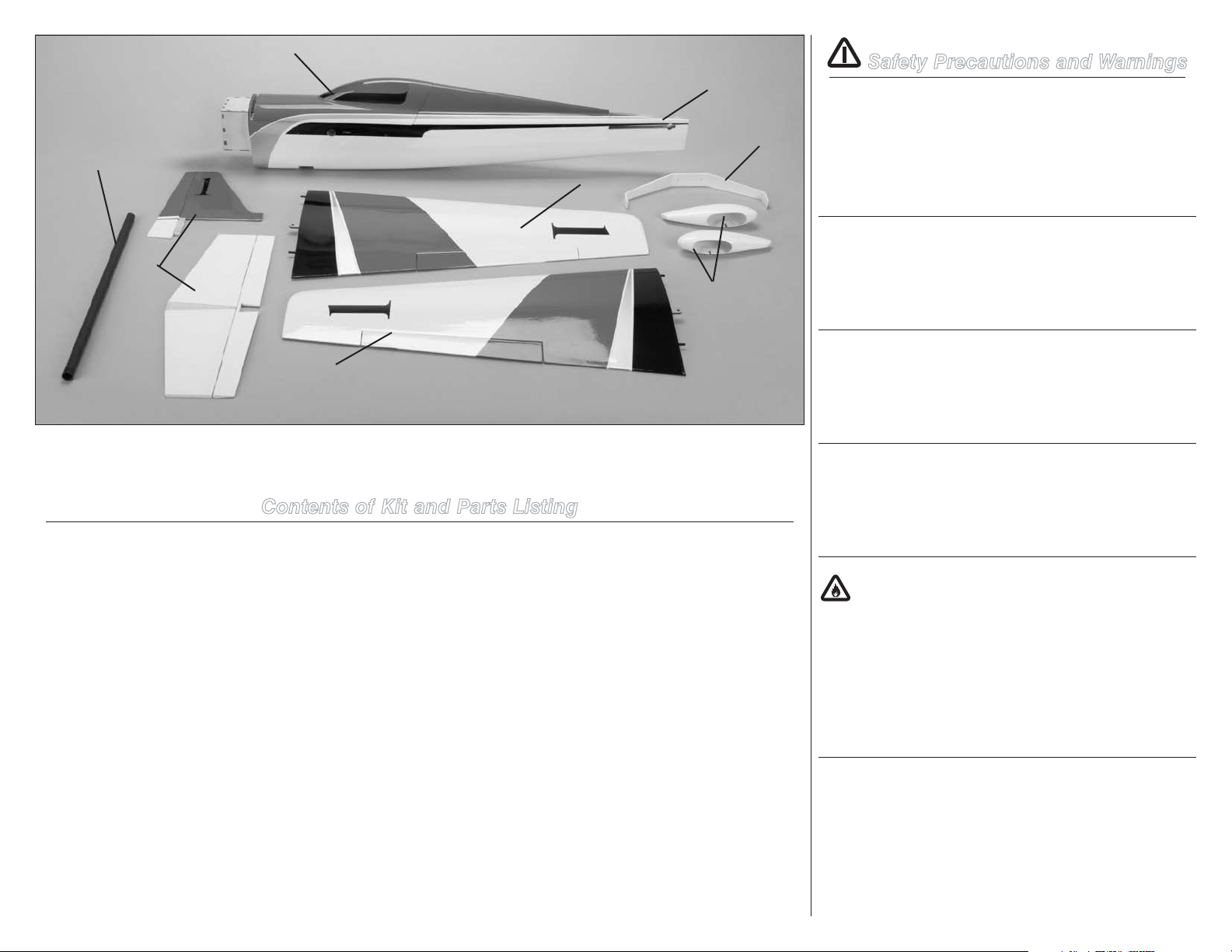
1. HAN452001 Fuselage with Hatch
2. HAN452002 Fuselage Top Hatch
3. HAN452003 Left Wing Panel
4. HAN452004 Right Wing Panel
5. HAN452005 Tail Set
6. HAN452007 Landing Gear
7. HAN452008 Wheel Pants (2)
8. HAN452010 Wing Tube, Carbon
Items not shown
HAN452006 Cowl
HAN452009 Axles (2)
HAN452011 Fuel Tank, 240cc
HAN452012 Wheels, 2-inch (51mm)
HAN452013 Engine Standoffs for EP, (22mm and
27mm) with hardware
HAN452014 Engine Mount with Hardware
HAN452015 Small Parts
HAN452016 Pushrods
BATTERIES
Notes on Lithium Polymer Batteries
When used improperly, lithium polymer batteries are
significantly more volatile than alkaline or Ni-Cd/Ni-MH
batteries used in RC applications. Always follow the
manufacturer’s instructions when using and disposing of any
batteries. Mishandling of Li-Po batteries can result in fire and
rupture causing serious injury and damage.
SMALL PARTS
HAN452017 Tail Wheel
HAN452018 Nylon Control Horn
This kit includes small parts and should not be left
unattended near children as choking and serious injury
could result.
4 Hangar 9 Sundowner 36 ARF
Page 5
Safe Operating Recommendations
•Inspectyourmodelbeforeeveryflighttomakecertainit
is airworthy.
•Beawareofanyotherradiofrequencyuserwhomay
present an interference problem.
•Alwaysbecourteousandrespectfulofotherusersof
your selected flight area.
•Chooseanareaclearofobstaclesandlargeenoughto
safely accommodate your flying activity.
•Makecertainthisareaisclearoffriendsandspectators
prior to launching your aircraft.
•Beawareofotheractivitiesinthevicinityofyourflight
path that could cause potential conflict.
•Carefullyplanyourflightpathpriortolaunch.
•AbidebyanyandallestablishedAMANationalModel
Aircraft Safety Code.
Important Information
Regarding Warranty
Please read our Warranty and Liability Limitations in the
back of this manual before building this product. If you as
the purchaser or user are not prepared to accept the liability
associated with the use of this Product, you are advised to
return this Product immediately in new and unused condition
to the place of purchase.
Using the Manual
This manual is divided into sections to help make assembly
easier to understand, and to provide breaks between each
major section. In addition, check boxes have been placed
next to each step to keep track of each step completed.
Steps with a single box () are performed once, while steps
with two or more boxes () indicate the step will require
repeating, such as for a right or left wing panel, two servos,
etc. Remember to take your time and follow the directions.
UltraCote® Covering Colors
White HANU870
True Red HANU866
Black HANU874
Silver HANU881
Recommended Setup–2-Stroke Glow
Evolution® .40NX with Muffler EVOE0401
APC Propeller, 9 x 7 APC09070
Recommended Setup–
Power 25 (NMPRA)
Power 25 BL Outrunner motor, 1250Kv EFLM54025B
APC Thin Electric Propeller, 8 x 8 APC08080E
60-Amp Pro Switch-Mode BEC ESC EFLA1060
2500mAh 4S 14.8V 30C Li-Po, 12AWG EFLB25004S30
Recommended Setup–
Power 32 (Sport)
Power 32 BL Outrunner motor, 770Kv EFLM54032A
APC Thin Electric Propeller, 12 x 8E APC12080E
60-Amp Pro Switch-Mode BEC ESC EFLA1060
3200mAh 4S 14.8V 30C Li-Po, 12AWG EFLB32004S30
Recommended Setup–
Power 32 (Speed)
Power 32 BL Outrunner motor, 770Kv EFLM54032A
APC Thin Electric Propeller, 10 x 10E APC10010E
60-Amp Pro Switch-Mode BEC ESC EFLA1060
2700mAh 5S 18.5V Pro Power Li-Po THP27005SP30
Transmitter Requirements
This model requires a minimum of a 4-channel radio to
operate all the functions of your aircraft. We suggest the
following radio systems available through Horizon Hobby or
your local hobby distributor.
Spektrum DX6i SPM6610
Spektrum DX7 SPMR7710
Spektrum DX8 SPM8810
®
Systems X9503 2.4GHz JRP2930
JR
JR Systems 12X 2.4GHz JRP1200
Radio Equipment Requirements
The following items are recommended when installing the
7-Channel AR7000 (SPMAR7010).
JR Chargeswitch JRPA004
Receiver Battery, 1100mAh, 4.8V Ni-Cd JRPB4240
DS388 Digital Micro Servo, MG (2) JRPS388
MN48 Mini Servo (2–3) JSP20040
6-inch (152mm) Servo Extension (2) JRPA095
AR7000 DSM2 7-Channel Receiver SPMAR7010
3-inch (76mm) Servo Extension (2) JRPA092
or
Y-harness, Heavy-Duty JRPA135
Servo Placement:
Aileron: DS388 Digital Micro Servo (2)
Rudder: MN48 Mini Servo
Elevator: MN48 Mini Servo
Throttle: MN48 Mini Servo (not required for EP
installations)
Optional Accessories
2-inch (54mm) Aluminum Spinner, EP EFLSP200
2-Blade Aluminum Spinner, 2-inch (54mm) HAN99000
1/4-28 Spinner Adapter Kit, GP HAN99053
Field Equipment Required
Fuel (15% recommended)
Long Reach Glow Plug Wrench HAN2510
Metered Glow Driver with Ni-Cd & Charger HAN7101
2-Cycle Sport Plug EVOGP1
Manual Fuel Pump HAN118
Optional Field Equipment
Glow:
PowerPro™ 12V Starter HAN161
12V 7Ah Sealed Battery HAN102
Power Panel HAN106
Blue Block After Run Oil EVOX1001
All:
Self-stick weights, 6 oz HAN3626
Spray cleaner
Paper towels
5Hangar 9 Sundowner 36 ARF
Page 6
Required Tools
Ball driver: 2.5mm Card stock
Drill Epoxy brush
Felt-tipped pen Flat file
Hobby scissors Hobby knife with #11 blade
Low-tack tape Measuring cup
Medium grit sandpaper Mixing cup
Mixing stick Nut driver: 5.5mm, 7mm
Open end wrench: 10mm Paper towels
Pencil Phillips screwdriver: #1, #2
Pin vise Razor saw
Rotary tool Rubbing alcohol
Ruler Sanding drum
Side cutter Square
String Tapered reamer
T-pins Hook and loop tape
Hook and loop strap
Drill bit: 1/16-inch (1.5mm), 5/64-inch (2mm), 7/64-inch
(2.5mm), 1/8-inch (3mm), 3/16-inch (5mm)
Hex wrench: 1.5mm, 2.5mm, 3mm
Required Adhesives
Elevator and Stabilizer Installation
Required Parts
Fuselage Wing panel (right and left)
Carbon wing tube
Stabilizer with elevator and hinges
Required Tools and Adhesives
15-minute epoxy Paper towel
Rubbing alcohol Low-tack tape
Pin vise Drill bit: 1/16-inch (1.5mm)
Felt-tipped pen Thin CA
Epoxy brush Measuring cup
Mixing stick Ruler
T-pins
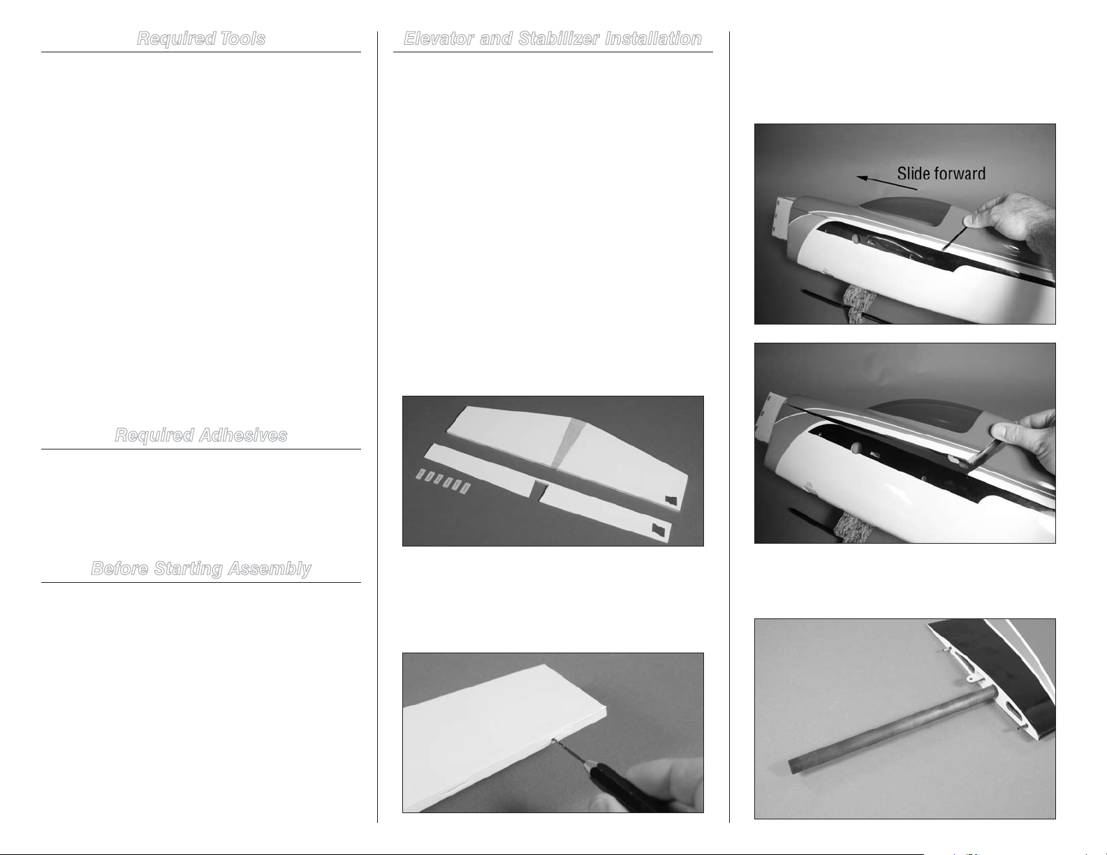
1. Separate the stabilizer and elevator. Use a small piece
of low-tack tape to mark one side of the stabilizer and
elevator so they can be repositioned easily. Set the six CA
hinges aside at this time.
3. Remove the canopy from the fuselage by sliding it
forward then lifting up at the rear of the canopy. The rear
is held in position using magnets and is also keyed to the
fuselage, while the front is held in place using pins that
extend into the bulkhead.
5-minute epoxy PAAPT38
15-minute epoxy MEUEPX15MIN
Medium CA PAAPT02
Thin CA PAAPT08
Threadlock PAAPT42
Before Starting Assembly
Before beginning the assembly of your model, remove
each part from its bag for inspection. Closely inspect the
fuselage, wing panels, rudder and stabilizer for damage. If
you find any damaged or missing parts, contact the place
of purchase.
If you find any wrinkles in the covering, use a heat gun
(HAN100) and covering glove (HAN150) or covering iron
(HAN101) with a sealing iron sock (HAN141) to remove
them. Use caution while working around areas where the
colors overlap to prevent separating the colors.
6 Hangar 9 Sundowner 36 ARF
2. Use a pin vise and 1/16-inch (1.5mm) drill bit to drill
a hole in the center of each hinge slot. This will provide
a tunnel for the CA to wick into, providing a better bond
between the wood and hinge when they are glued in position.
Prepare both the stabilizer and elevator at this time.
4. Locate the carbon wing tube. Slide the tube into one
of the wing panels. It will slide in easily, so do not force it
further than it will easily slide.
Page 7
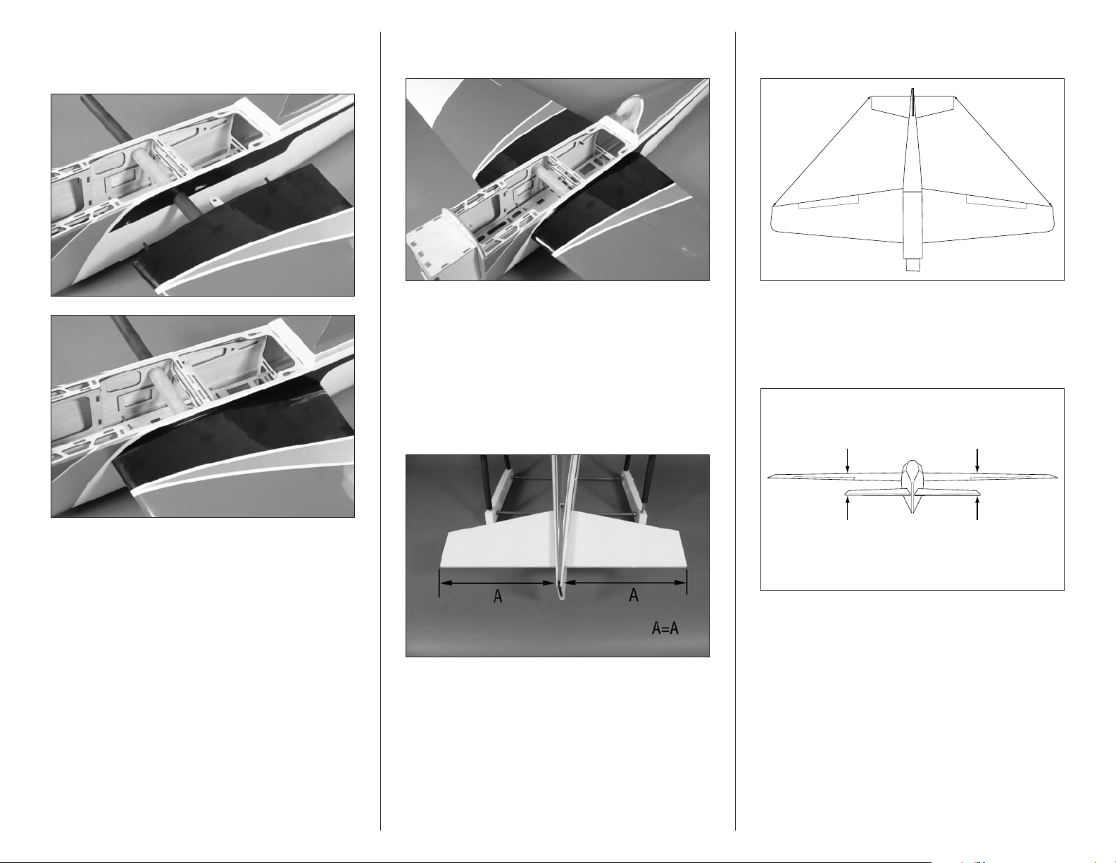
5. Slide the tube and wing panel into position on
A A
A=A
Check Alignment
the fuselage. The wing will fit tight against the fuselage
when installed.
6. Slide the remaining wing panel into position against
the fuselage.
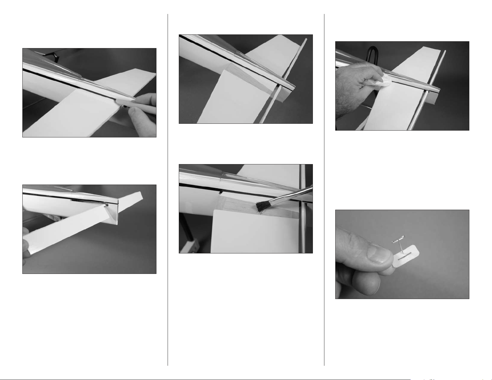
8. Measure from each wing tip to each stabilizer tip. Position
the stabilizer so both measurements are equal as shown.
Note: The wing does not need to be secured to
the fuselage at this time. It is only being installed
so the position of the stabilizer can be adjusted.
Important: The stabilizer must be aligned to the wing
as shown in the following steps. Not doing so may
require excessive trim to correct for misalignment,
which can reduce the performance of the model.
7. Slide the stabilizer in the slot at the rear of the
fuselage. Position the stabilizer as far forward in the slot as
possible. Check to make sure the stabilizer is centered in the
fuselage as shown below.
9. Check the alignment of the stabilizer to the wing by
standing back 6–8 feet (2–3 meters). The distance between
the wing and stabilizer must be equal as shown. If not,
lightly sand the opening in the fuselage for the stabilizer to
correct the alignment.
7Hangar 9 Sundowner 36 ARF
Page 8
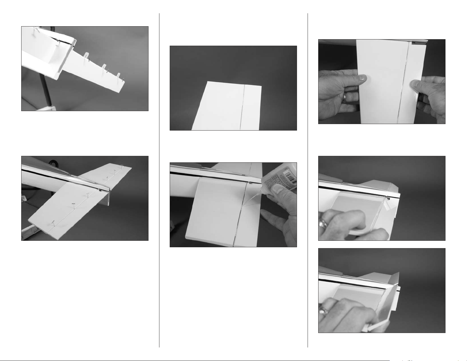
10. Once the alignment has been set, use a felt-tipped
pen to mark the outline of the fuselage on the stabilizer. This
will allow easy repositioning as it will be removed in the
following step.
11. Remove the stabilizer from the fuselage. Note the
direction of the top and bottom of the stabilizer indicated
by the tape placed on it back in step 1. Slide the elevator
into the slot, noting the top and bottom to match that of the
stabilizer that was just removed.
12. Slide the stabilizer back into position in the fuselage.
Leave the stabilizer so the exposed wood can be accessed.
13. Mix 1/2 ounce (15mL) of 15-minute epoxy. Use an
epoxy brush to apply the epoxy to the exposed wood on both
the top and bottom of the stabilizer. Make sure not to get any
epoxy on the elevator.
14. Slide the stabilizer in position. Use a paper towel and
rubbing alcohol to remove any epoxy that oozes out when
the stabilizer is positioned.
15. Before the epoxy can cure, make sure to check the
alignment of the stabilizer as described in steps 7 through
9. It is very important the stabilizer is positioned correctly
before the epoxy begins to cure, as it will be difficult to
readjust its position after the epoxy has cured. Do not
proceed until the epoxy has fully cured.
16. Remove the wing panels and wing tube at this time.
Place a T-pin in the center of the six hinges removed in step 1.
This will center the hinges evenly in the stabilizer and elevator.
Note: Read steps 12 through 15 before mixing
any epoxy. You must be able to complete these
steps before the epoxy begins to cure.
8 Hangar 9 Sundowner 36 ARF
Page 9
17. Place the hinges in the elevator.
18. Carefully position the elevator so the hinges are
inserted into the stabilizer. Make sure that all the hinges get
installed, and that none get folded over accidentally. The
elevator will fit tightly against the stabilizer as shown. Use
the T-pins as handles to help in positioning the hinges.
19. Remove the T-pins from the hinges. Make sure the
elevator is pressed tightly against the stabilizer to eliminate
any hinge gap. Check that the tips of the elevator and
stabilizer are aligned.
20. Saturate each hinge using thin CA on both the
top and bottom of the hinge. Allow the CA to fully cure
before proceeding.
21. Once the CA has cured, gently pull on the stabilizer
and elevator to make sure the hinges are glued securely. If
any hinges are loose, apply more CA and check them again.
22. Flex the elevator through its range of motion a
number of times to break in the hinges. This will reduce the
load on the servo for those first flights.
Note: Do not use CA accelerator on the
hinges. The CA must be allowed time to
soak into the hinge and surrounding wood
to provide the best bond for the hinge.
9Hangar 9 Sundowner 36 ARF
Page 10
Rudder, Fin and Tail Wheel Installation
Required Parts
Fuselage Aluminum tail wheel bracket
Tail gear wire Fin with rudder and hinges
Tail wheel, 1-inch (25mm)
2mm x 8mm self-tapping screw (2)
Wheel collar with setscrew, 1.5mm
Required Tools and Adhesives
Ruler Hex wrench: 1.5mm
Phillips screwdriver: #1 Hobby knife with #11 blade
Rubbing alcohol 15-minute epoxy
Medium grit sandpaper Thin CA
Low-tack tape Mixing cup
Mixing stick Epoxy brush
Felt-tipped pen Square
Paper towel Pin vise
T-pins Threadlock
Drill bit: 1/16-inch (1.5mm)
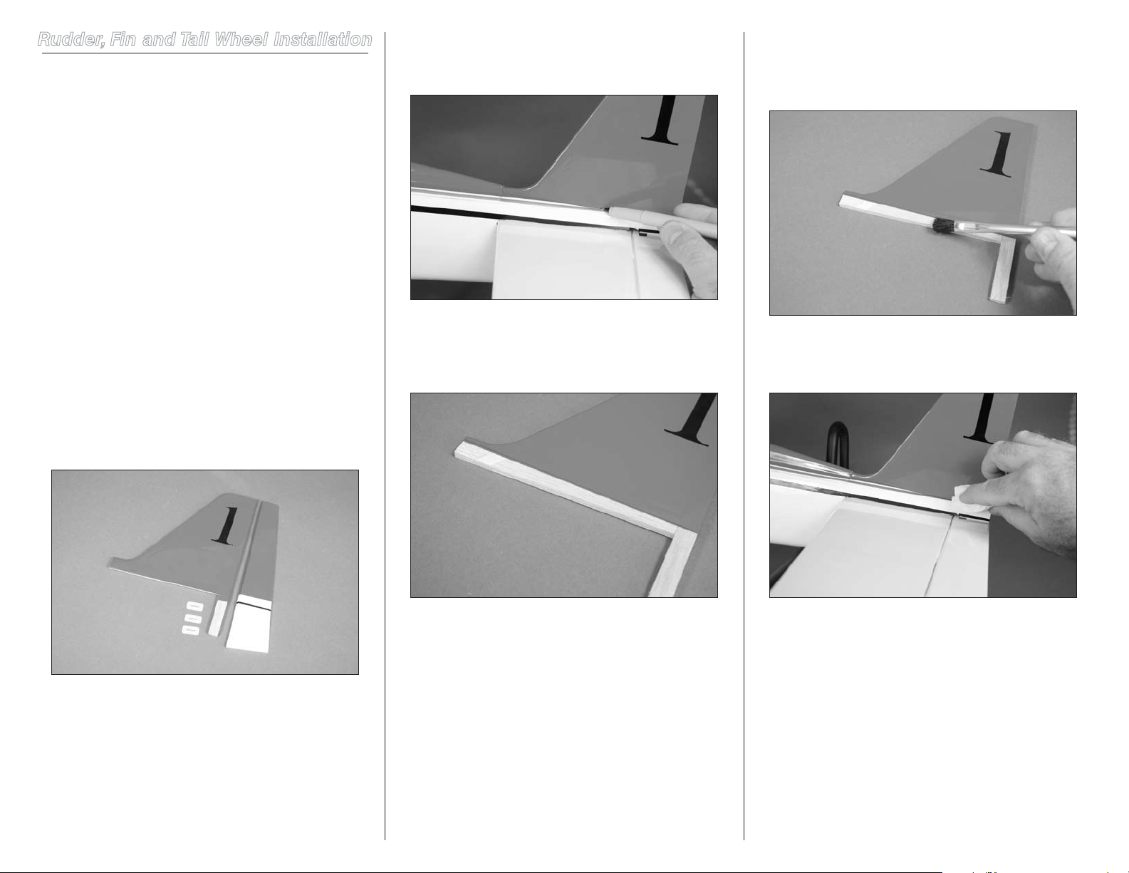
1. Locate the fin and rudder. Separate the fin from the
rudder and set the rudder and three hinges aside.
2. Test fit the fin at the rear of the fuselage. Slide the fin
as far forward as possible. Use a felt-tipped pen to transfer
the outline of the fuselage to the fin.
3. Remove the fin from the fuselage. Use a straight edge
and hobby knife with a new #11 blade to trim the covering
1/16-inch (1.5mm) below the line on the fin to expose the
underlying wood.
4. Mix 1/4 ounce (15mL) of 15-minute epoxy. Use an
epoxy brush to apply the epoxy to the exposed wood on the
fin. Also apply a small amount of epoxy in the slot in the
fuselage where the fin fits.
5. Fit the fin into the fuselage. Use a paper towel and
rubbing alcohol to remove any excess epoxy that oozes out
when the fin is installed.
Note: When cutting through the covering, use very
light pressure or a hot knife to trim the covering.
If the underlying wood becomes damaged, the fin
may fail in flight, causing the loss of your model.
Note: Read steps 4 through 7 before mixing
any epoxy. You must be able to complete these
steps before the epoxy begins to cure.
10 Hangar 9 Sundowner 36 ARF
Page 11
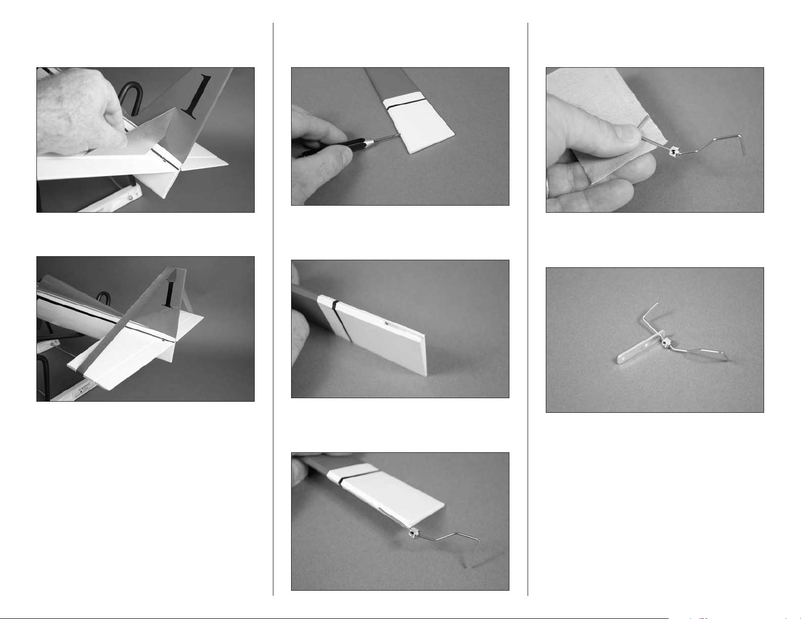
6. Use a square to check that the fin is square to the
stabilizer. There will be a slight amount of play to correct for
any alignment issues.
8. Use a pin vise and 1/16-inch (1.5mm) drill bit to drill a
hole that is 1/2-inch (13mm) deep 7/8-inch (22mm) from the
bottom of the rudder.
11. Remove the tail gear wire from the rudder. Use
medium grit sandpaper to roughen the tail gear wire where it
contacts the rudder.
7. Use low-tack tape to hold the fin in position until the
epoxy fully cures.
9. Use a hobby knife and #11 blade to cut a groove from
the hole drilled in the previous step to the bottom of the
rudder for the tail gear wire.
10. Test fit the tail gear wire into the rudder. The wire will
rest flush with the hinge line of the rudder as shown. You may
need to adjust the groove in the rudder to fit the tail gear wire.
12. Slide the aluminum tail wheel bracket on the tail gear
wire. The two larger holes are used for mounting the bracket,
while the smaller hole fits over the wire.
11Hangar 9 Sundowner 36 ARF
Page 12
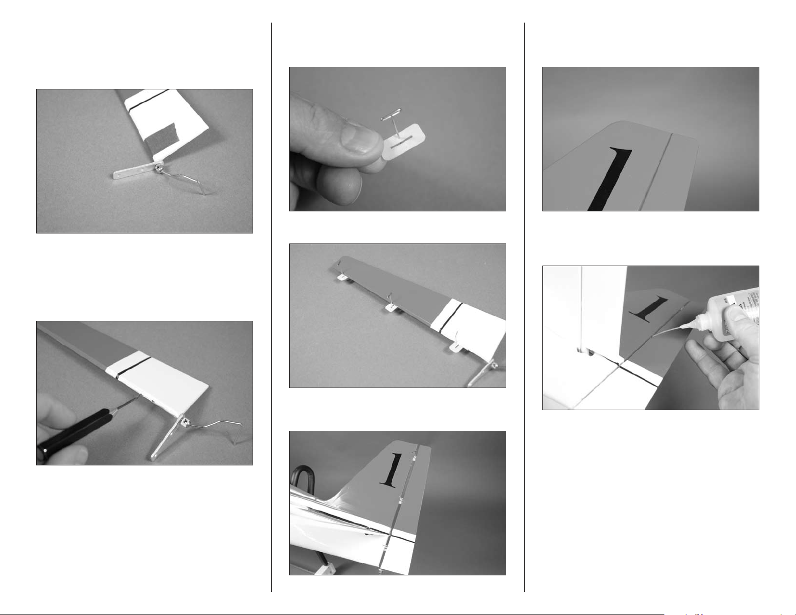
13. Mix a small amount of 15-minute epoxy. Apply the
epoxy to the notch in the rudder and the tail gear wire where
it fits in the rudder. Insert the wire and use low-tack tape to
hold the wire in position until the epoxy cures. Remove any
excess epoxy using rubbing alcohol and a paper towel.
15. Place a T-pin in the center of the three hinges
removed in step 1. This will center the hinges evenly in the
rudder and fin.
18. Remove the T-pins from the hinges. Make sure the
rudder is pressed tightly against the fin to eliminate any hinge
gap. Check that the tips of the rudder and fin are aligned.
14. Remove the tape from the rudder holding the tail gear
wire in position. Use a pin vise and 1/16-inch (1.5mm) drill
bit to drill a hole in the center of each hinge slot. This will
provide a tunnel for the CA to wick into, providing a better
bond between the wood and hinge when they are glued in
position. Prepare both the rudder and fin at this time.
16. Place the hinges in the rudder.
17. Remove the tape placed on the fin and stabilizer in
step 7. Slide the hinges into the slots in the rudder.
19. Saturate each hinge using thin CA on both the
top and bottom of the hinge. Allow the CA to fully cure
before proceeding.
Note: Do not use CA accelerator on the
hinges. The CA must be allowed time to
soak into the hinge and surrounding wood
to provide the best bond for the hinge.
12 Hangar 9 Sundowner 36 ARF
Page 13
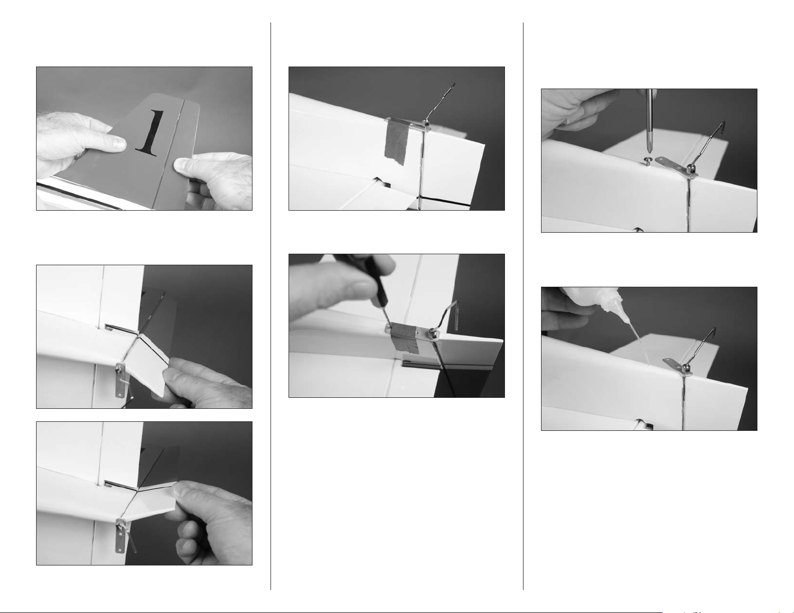
20. Once the CA has cured, gently pull on the rudder and
fin to make sure the hinges are glued securely. If any hinges
are loose, apply more CA and check them again.
22. Use a piece of low-tack tape to tape the tail wheel
bracket to the bottom of the fuselage. Make sure the mounting
holes in the bracket are aligned with the fuselage centerline.
24. Remove the tape and swing the bracket to the side.
Thread a 2mm x 8mm self-tapping screw into each hole
to cut threads in the surrounding wood using a #1 Phillips
screwdriver. Remove the screw before proceeding to the
next step.
21. Flex the rudder through its range of motion a number
of times to break in the hinges. This will reduce the load on
the servo for those first flights.
23. Use a pin vise and 1/16-inch (1.5mm) drill bit to drill
the two holes in the fuselage for the mounting screws.
25. Place 2–3 drops of thin CA in each hole to harden
the surrounding wood. Doing so will make the screws more
secure, preventing them from vibrating loose.
13Hangar 9 Sundowner 36 ARF
Page 14
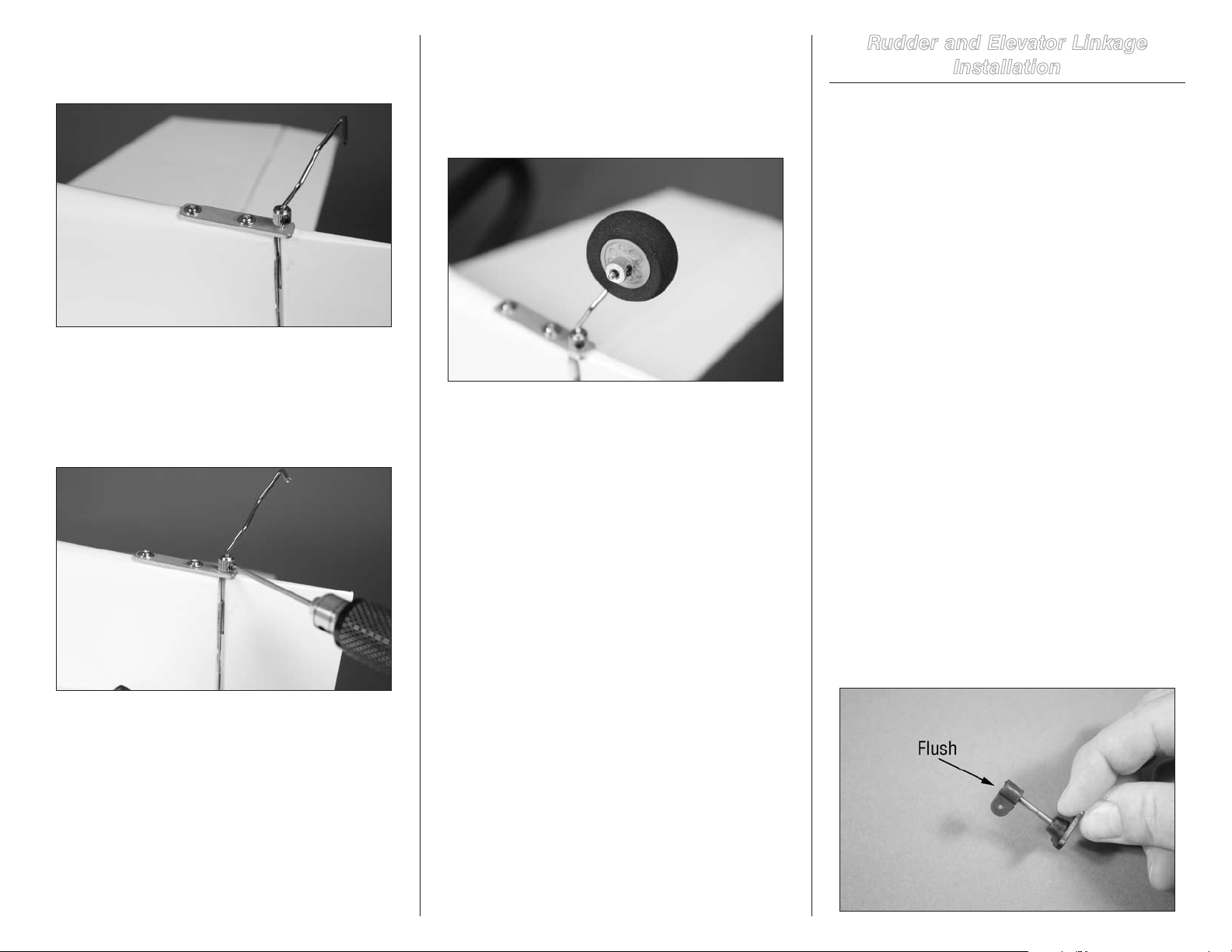
26. Secure the tail wheel bracket to the fuselage
using two 2mm x 8mm sheet metal screws and a #1
Phillips screwdriver.
Note: Always use threadlock on metal-to-metal
fasteners to prevent them from vibrating loose.
27. Use a 1.5mm hex wrench to loosen the setscrew in
the wheel collar. Slide the wheel collar against the tail wheel
bracket and tighten the setscrew to secure its location.
Note: Always use threadlock on metal-to-metal
fasteners to prevent them from vibrating loose.
28. Attach the tail wheel to the tail wheel bracket using
a 1.5mm wheel collar. Tighten the setscrew using a 1.5mm
hex wrench.
Rudder and Elevator Linkage
Installation
Required Parts
Fuselage assembly Servo with hardware (2)
Transmitter Receiver
Receiver battery Nylon clevis (2)
Control horn fitting (2) Threaded control horn (2)
Control horn backplate (2)
2mm x 12mm machine screw (6)
7
21
/8-inch (555mm) pushrod, rudder
1
20
/4-inch (514mm) pushrod, elevator
Required Tools and Adhesives
Thin CA Hobby knife with #11 blade
Phillips screwdriver: #1 Pencil
Felt-tipped pen Pin vise
Ruler
Drill bit: 1/16-inch (1.5mm), 5/64-inch (2mm)
Note: Before starting the installation of the servos,
we recommend centering the trims and sticks on
your transmitter. If using a computer radio, make
sure to reset a model memory and name it for this
particular model. We also recommend binding the
transmitter and receiver at this time following the
instructions provided with your radio system.
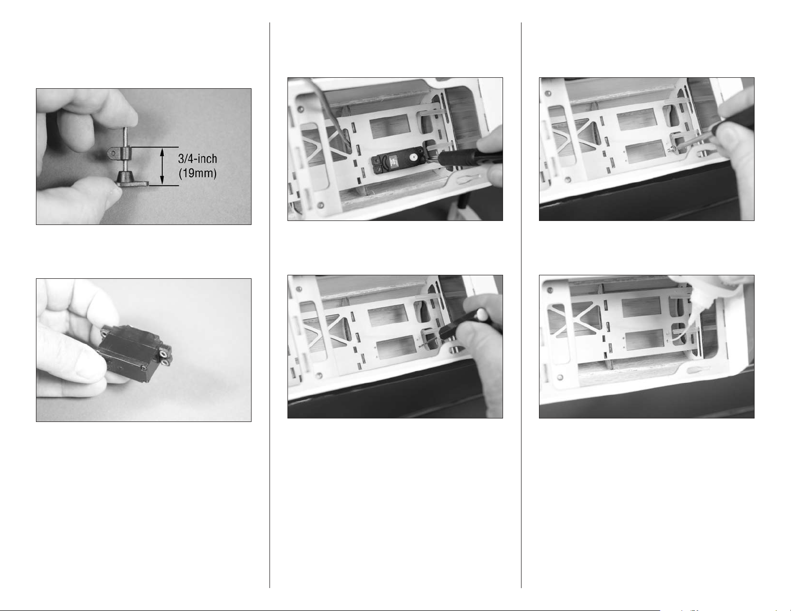
1. Prepare the elevator control horn by threading the
control horn fitting on the control horn so the top of
the fitting is flush with the top of the threads. It may be
necessary to hold the screw using a #1 Phillips screwdriver
while installing the fitting.
14 Hangar 9 Sundowner 36 ARF
Page 15
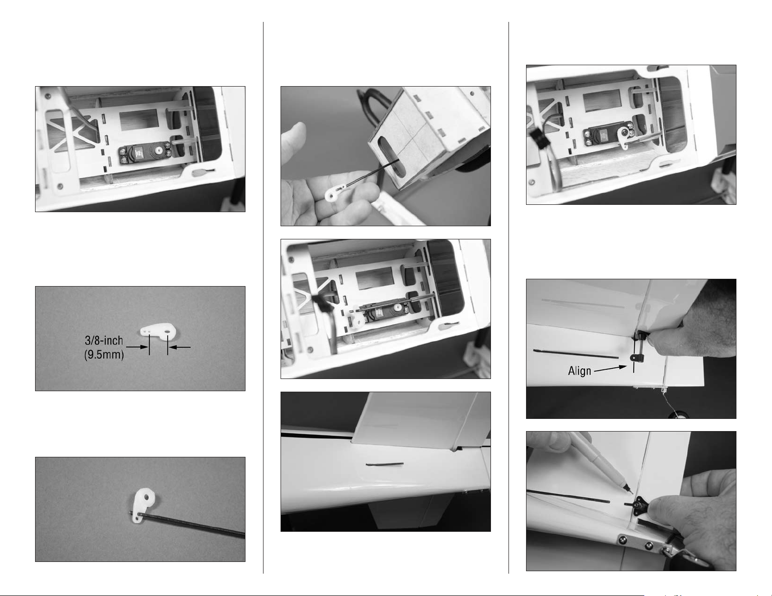
2. Prepare the rudder control horn by threading the
control horn fitting on the control horn so the top of the
fitting measures 3/4-inch (19mm) from the base of the horn.
It may be necessary to hold the screw using a #1 Phillips
screwdriver while installing the fitting.
4. Test fit the elevator servo in the opening in the left-
hand side of the fuselage. Make sure the output of the servo
faces to the rear of the fuselage. Use a pencil to transfer the
locations of the servo mounting screws on the servo tray.
6. Use a #1 Phillips screwdriver to run a servo
mounting screw in each of the holes to cut threads in the
surrounding wood. Remove the screw before proceeding to
the next step.
3. Prepare the servo by installing the rubber grommets
and brass eyelets. Remove the servo horn from the servo
using a #1 Phillips screwdriver.
Note: The grommets install from
the bottom of the servo.
5. Remove the servo from the fuselage. Use a pin
vise and 1/16-inch (1.5mm) drill bit to drill the holes for the
servo mounting screws.
7. Apply 2–3 drops of thin CA in each hole to harden
the surrounding wood. This will help prevent the screws
from vibrating loose.
15Hangar 9 Sundowner 36 ARF
Page 16
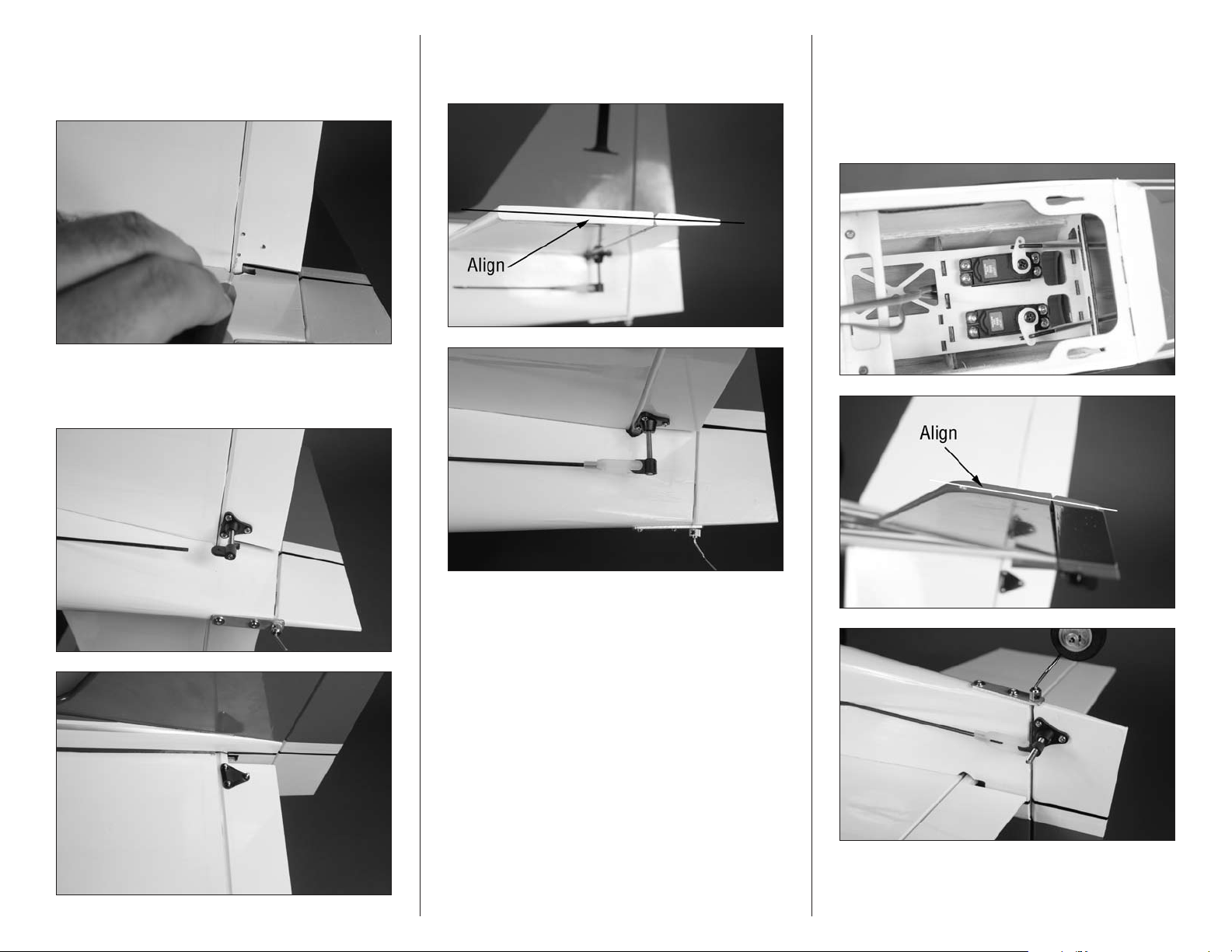
8. Secure the elevator servo in the fuselage using the
screws provided with the servo and a #1 Phillips screwdriver.
Make sure the output of the servo faces to the rear when
installed in the fuselage. Route the servo lead through the
servo tray in the location shown in the photo.
11. Slide the pushrod into the pushrod tube near the
servo. Inserting the pushrod through the oval hole in the
firewall will make its installation easier. You will need to use a
hobby knife to remove the covering at the rear of the fuselage
for the pushrod to exit the left-hand side of the fuselage.
12. Use the radio system to center the elevator servo.
Use a #1 Phillips screwdriver and the screw removed from
the servo to attach the servo horn to the servo.
9. Prepare the servo horn by enlarging the hole in the
arm that is 3/8-inch (9.5mm) from the center of the servo
horn using a pin vise and 5/64-inch (2mm) drill bit. Use side
cutters to remove any other arms from the horn so they
don’t interfere with the operation of the servo.
10. Insert the bend on the 20
pushrod into the hole enlarged in the previous step. The
wire will be on the top of the horn, while the bend will end
underneath the horn.
1
/4-inch (514mm)
13. Position the control horn prepared in step 1
on the elevator so the hole in the fitting is aligned with
the hinge line, and the fitting is pointing directly at the
pushrod. Use a felt-tipped pen to transfer the locations for
the three mounting holes onto the elevator.
16 Hangar 9 Sundowner 36 ARF
Page 17
14. Use a pin vise and 5/64-inch (2mm) drill bit to
drill the three holes for the control horn mounting screws.
Apply 2–3 drops of thin CA in each hole to harden the
surrounding wood.
15. Use a #1 Phillips screwdriver to secure the control
horn to the elevator using three 2mm x 12mm machine
screws and a control horn backplate.
16. With the elevator servo centered, thread the nylon
clevis on the pushrod wire. When the clevis is attached, the
control surface must be centered as shown.
17. Install rudder servo and the 21
rudder pushrod following steps 3 through 15. Use
the rudder control horn prepared in step 2. The only
difference is that the rudder servo mounts on the righthand side and the pushrod routes out the right side of the
fuselage.
7
/8-inch (555mm)
18. Remember to turn off the radio system at this time to
avoid running the battery down.
17Hangar 9 Sundowner 36 ARF
Page 18
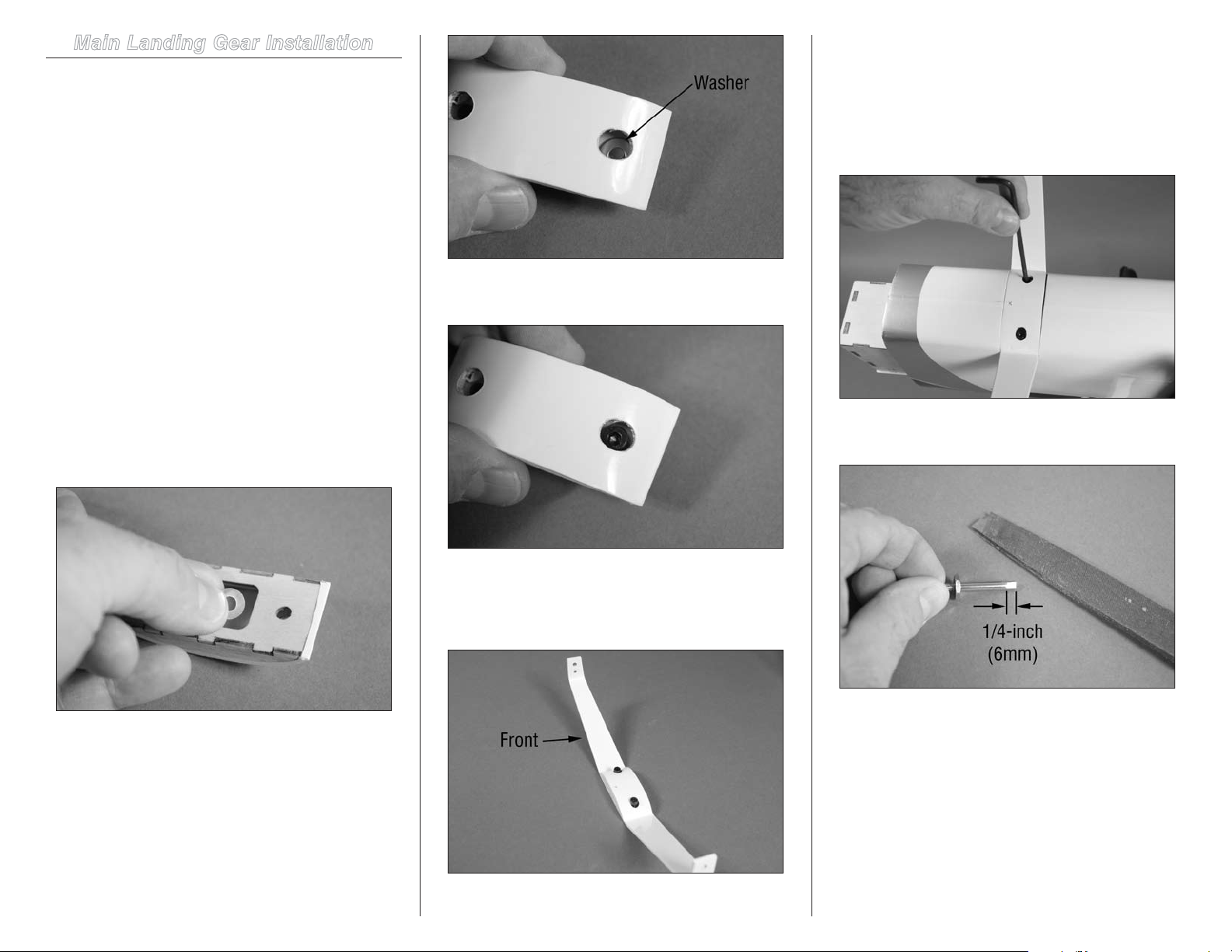
Main Landing Gear Installation
Note: Always use threadlock on metal-to-metal
fasteners to prevent them from vibrating loose.
Required Parts
Fuselage assembly Main landing gear
Axle, 4mm (2) Wheel pant (right and left)
Locknut, 4mm (2) 4mm washer (4)
Landing gear cover
2mm x 8mm self-tapping screw (2)
4mm x 12mm socket head bolt (2)
Wheel collar, 4mm with setscrew (2)
Main wheel, 2-inch (52mm) (2)
Required Tools and Adhesives
Nut driver: 7mm Open-end wrench: 10mm
Ruler Threadlock
Flat file Light oil
Ruler Felt-tipped pen
Hex wrench: 1.5mm, 2mm, 3mm
1. Carefully slide two 4mm washers inside the landing
gear cover. Turn the cover over and align the washers over
the holes in the cover.
4. Attach the landing gear to the fuselage using the
screws installed in step 2 and a 3mm hex wrench. Use a
paper towel and rubbing alcohol to remove the mark made
in step 1.
2. Insert the 4mm x 12mm socket head screws through
the washers and the landing gear cover.
5. Use a flat file to make a flat area on the axle that is
1/4-inch (6mm) wide as shown.
3. Place the landing gear cover assembly on the landing
gear. Note that the landing gear will angle forward as shown
in the photo. The screws will fit into the mounting holes in
the landing gear.
Note: Always use threadlock on metal-to-metal
fasteners to prevent them from vibrating loose.
18 Hangar 9 Sundowner 36 ARF
Page 19
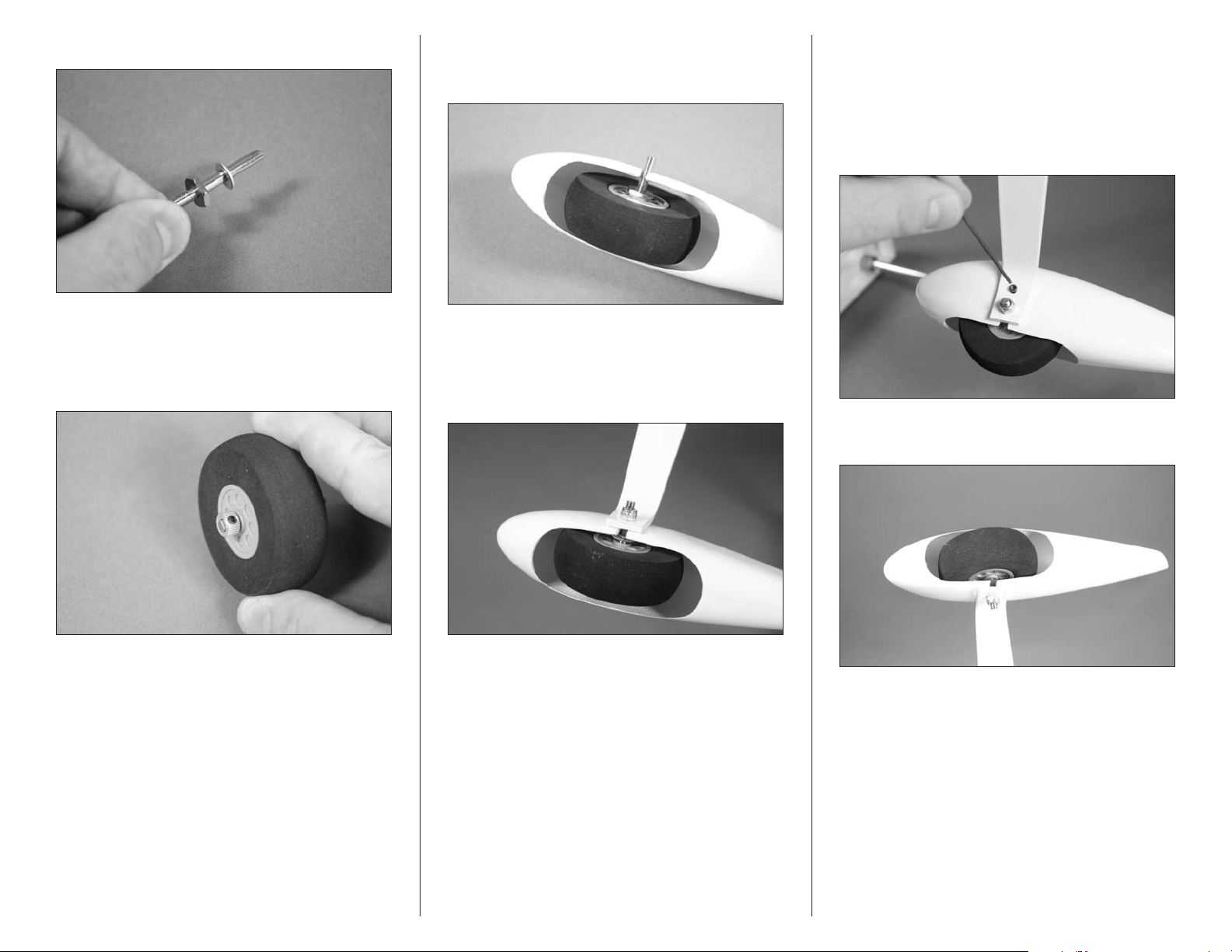
6. Slide a 4mm washer on the axle as shown.
8. Insert the wheel assembly into one of the wheel
pants. The threaded portion of the axle will fit into the notch
of the wheel pant.
Note: Always use threadlock on metal-to-metal
fasteners to prevent them from vibrating loose.
10. Use a 2mm hex wrench to reinstall the 2.5mm x
10mm socket head machine screw. Use a 10mm open-end
wrench and a 7mm nut driver to fully tighten the nut on the
axle.
7. Place a drop of light machine oil on the axle so the
wheel can rotate easily. Slide the wheel on the axle, then
secure it with a 4mm wheel collar. Install the collar so it is
flush with the end of the axle. Tighten the setscrew on the
flat made in the previous step using a 1.5mm hex wrench.
9. Insert the threaded portion of the axle through
the larger hole of the landing gear. Use a 10mm open-end
wrench and 7mm nut driver to tighten the 4mm nut that
secures the axle. Leave the nut a little loose so the wheel
pant can be moved easily for adjustment.
11. Repeat steps 5 through 10 to install the remaining
wheel and wheel pant.
19Hangar 9 Sundowner 36 ARF
Page 20
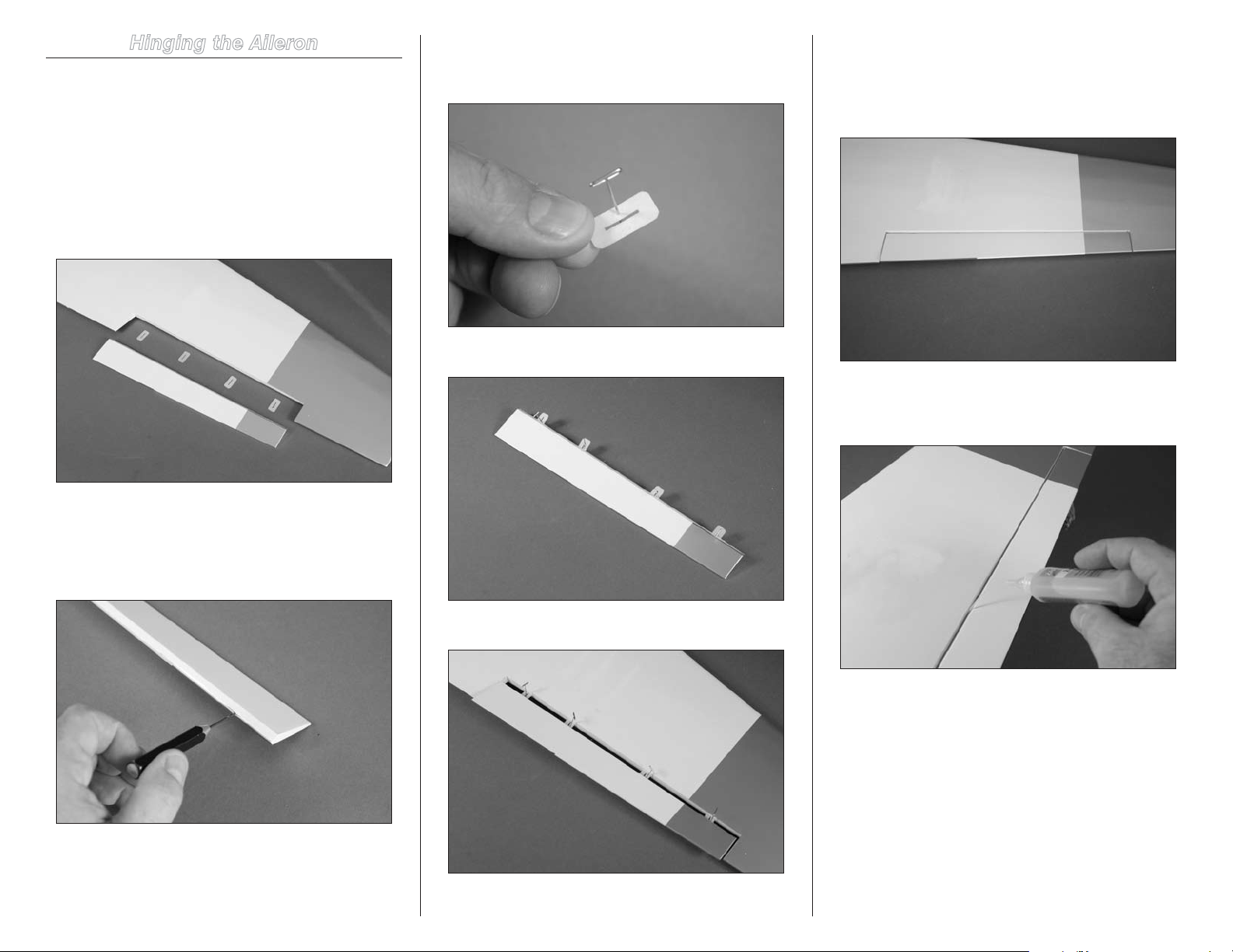
Hinging the Aileron
Required Parts
Wing panel with aileron and hinges (right and left)
Required Tools and Adhesives
Pin vise Thin CA
T-pins Drill bit: 1/16-inch (1.5mm)
1. Separate the aileron from the wing panel and set the
four hinges aside.
3. Place a T-pin in the center of the four hinges
removed in step 6. This will center the hinges evenly in the
rudder and fin.
4. Place the hinges in the aileron.
6. Remove the T-pins from the hinges. Make sure the
aileron is pressed tightly against the wing panel to eliminate
any hinge gap. Check that the ends of the aileron have an
equal gap and are centered in the opening for the aileron in
the wing panel.
7. Saturate each hinge using thin CA on both the
top and bottom of the hinge. Allow the CA to fully cure
before proceeding.
2. Use a pin vise and 1/16-inch (1.5mm) drill bit to
drill a hole in the center of each hinge slot. This will provide
a tunnel for the CA to wick into, providing a better bond
between the wood and hinge when they are glued in position.
Prepare both the aileron and wing panel at this time.
5. Slide the hinges into the slots in the wing panel.
Note: Do not use CA accelerator on the
hinges. The CA must be allowed time to
soak into the hinge and surrounding wood
to provide the best bond for the hinge.
20 Hangar 9 Sundowner 36 ARF
Page 21
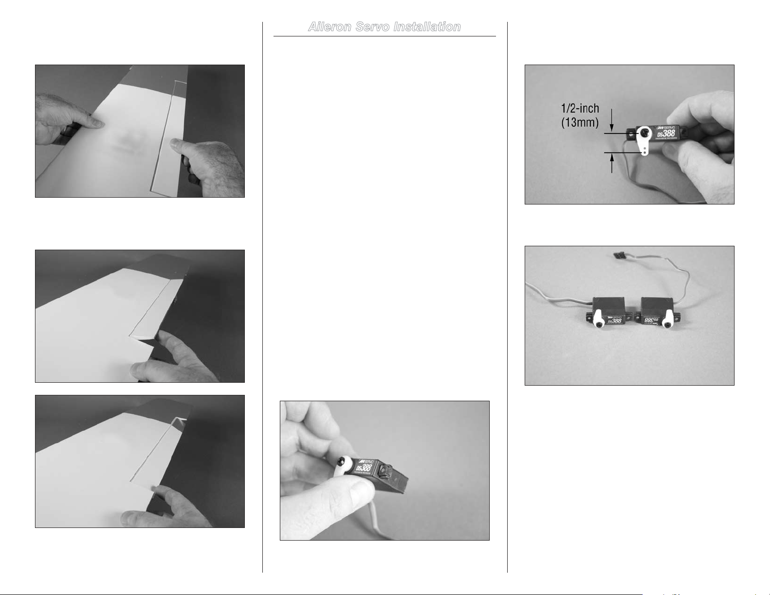
8. Once the CA has cured, gently pull on the wing and
aileron to make sure the hinges are glued securely. If any
hinges are loose, apply more CA and check them again.
9. Flex the aileron through its range of motion a
number of times to break in the hinges. This will reduce the
load on the servo for those first flights.
Aileron Servo Installation
Required Parts
Servo with hardware (2) Aileron servo cover (2)
Transmitter Receiver
Receiver battery
2mm x 8mm self-tapping screw (8)
6-inch (152mm) servo extension (2)
Wing panel with aileron (right and left)
5/16 x 5/16 x 5/8-inch (8mm x 8mm x 15mm)
hardwood block (4)
Required Tools and Adhesives
Drill Pin vise
Pencil Trim seal tool
Phillips screwdriver: #1 Thin CA
Ruler Hobby knife with #11 blade
Side cutter String/music wire
Hobby scissors Medium grit sandpaper
Rotary tool Sanding drum
5-minute epoxy Mixing stick
Mixing cup
Drill bit: 1/16-inch (1.5mm, 5/64-inch (2mm)
2. Use a pin vise and 5/64-inch drill bit to enlarge
the hole in the servo arm that is 1/2-inch (13mm) from the
center of the horn as shown.
3. Repeat step 1 to prepare a second aileron servo. Note
the servos will be mirror images of each other.
10. Repeat steps 1 through 9 to hinge the
remaining aileron.
1. Prepare the aileron servo by installing the rubber
grommets and brass eyelets. Center the servo using the
radio system. Use side cutters to remove any arms from the
horn that may interfere with the operation of the servo. Use a
#1 Phillips screwdriver to attach the servo horn to the servo
using the hardware provided with the servo.
21Hangar 9 Sundowner 36 ARF
Page 22
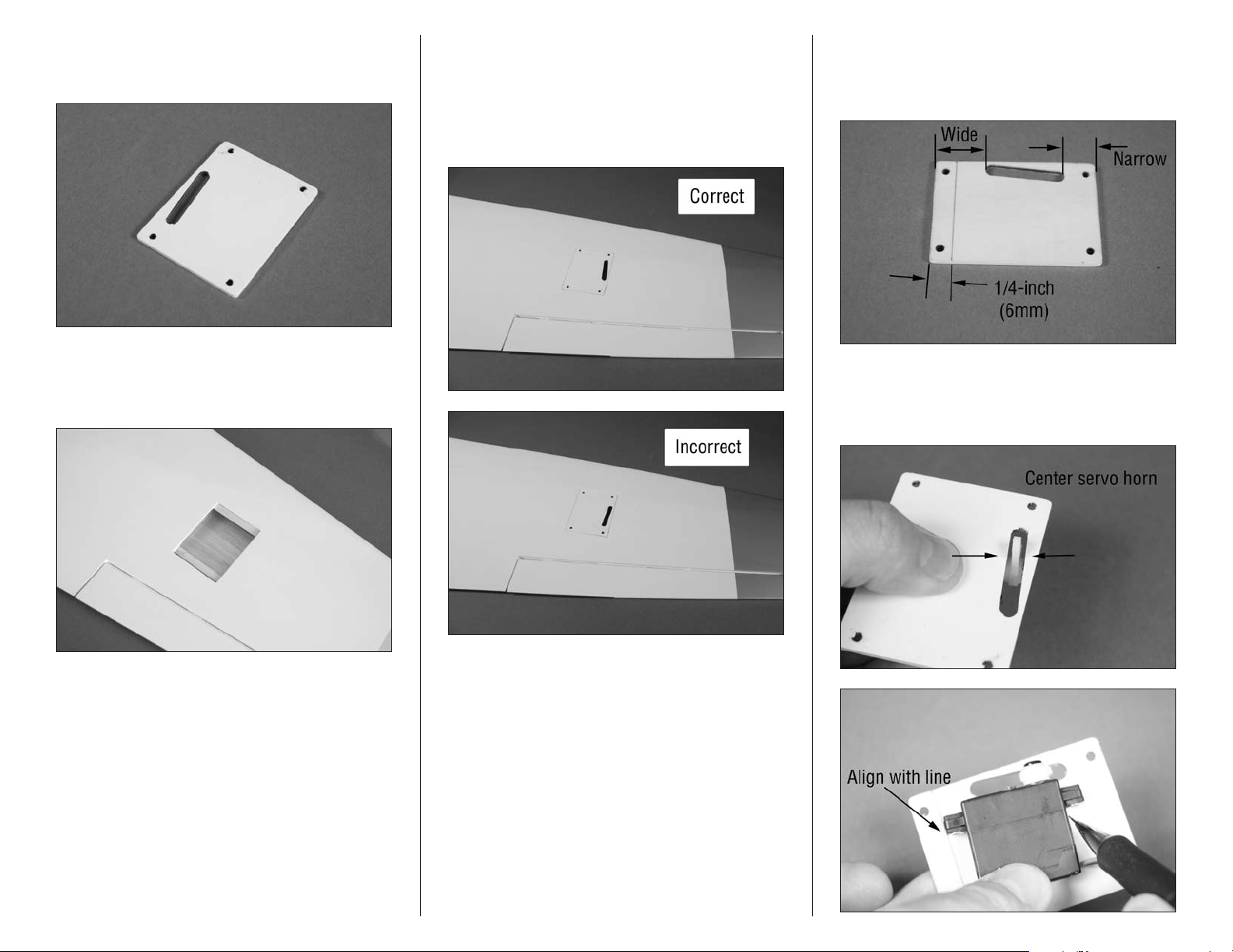
4. Use a hobby knife and #11 blade to remove the
covering to expose the slot for the servo horn and mounting
screw locations in the servo cover.
5. Use a hobby knife with a #11 blade to trim the
covering 1/16-inch (1.5mm) inside the opening for the
aileron servo in the wing. Use a trim seal tool to iron the
covering down around the edges for a finished opening.
6. Repeat steps 4 and 5 to prepare the remaining aileron
servo cover and hinge the remaining aileron.
7. Check the fit of the aileron servo cover to the wing.
Note that there is a left and right cover as shown in the
following photos. Make sure to select the correct cover for
the wing panel.
8. Use a pencil and ruler to draw a line on the cover
1/4-inch (6mm) from the edge of the cover. The line is
located on the end of the cover that has the wider area
between the slot and edge of the cover.
9. Position the servo on the cover so the horn is
centered in the width of the slot. Align the edge of the servo
with the line drawn in the previous step. Use a pencil to mark
the location of the servo mounting tabs.
22 Hangar 9 Sundowner 36 ARF
Page 23
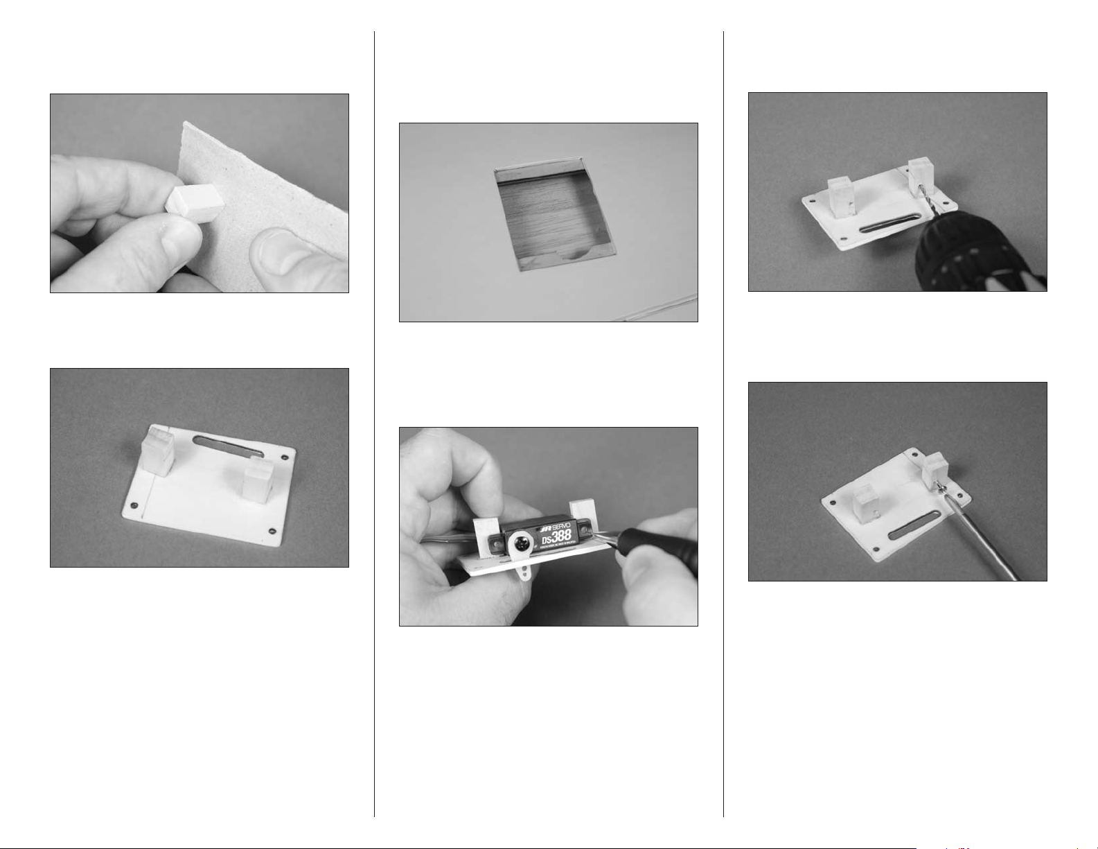
10. Sand the 5/16 x 5/16 (8mm x 8mm) end of the
hardwood block. This will be the end glued to the plate in the
following step. Prepare two blocks at this time.
12. Test fit the servo cover in the opening in the wing.
It may be necessary to notch the cover support rail to clear
the hardwood block. Use a rotary tool and sanding drum to
carefully notch the rail, being careful not to sand the wing
sheeting or remove too much material from the rail.
14. Use a drill and 5/64-inch (2mm) drill bit to drill the
holes for the mounting screws. Use care not to enlarge the
holes any larger than the drill bit.
11. Use 5-minute epoxy to glue the square end of the
hardwood block to the servo cover using the marks made in
step 18. Allow the epoxy to fully cure before proceeding.
13. Position the servo between the two blocks.
Leave a small gap between the servo and servo cover so
vibrations from the airframe are not transferred directly to
the servo. Use a pencil to mark the locations for the two
servo mounting screws on the blocks.
15. Use a #1 Phillips screwdriver to run a servo
mounting screw in each of the holes to cut threads in the
surrounding wood. Remove the screw before proceeding to
the next step.
23Hangar 9 Sundowner 36 ARF
Page 24
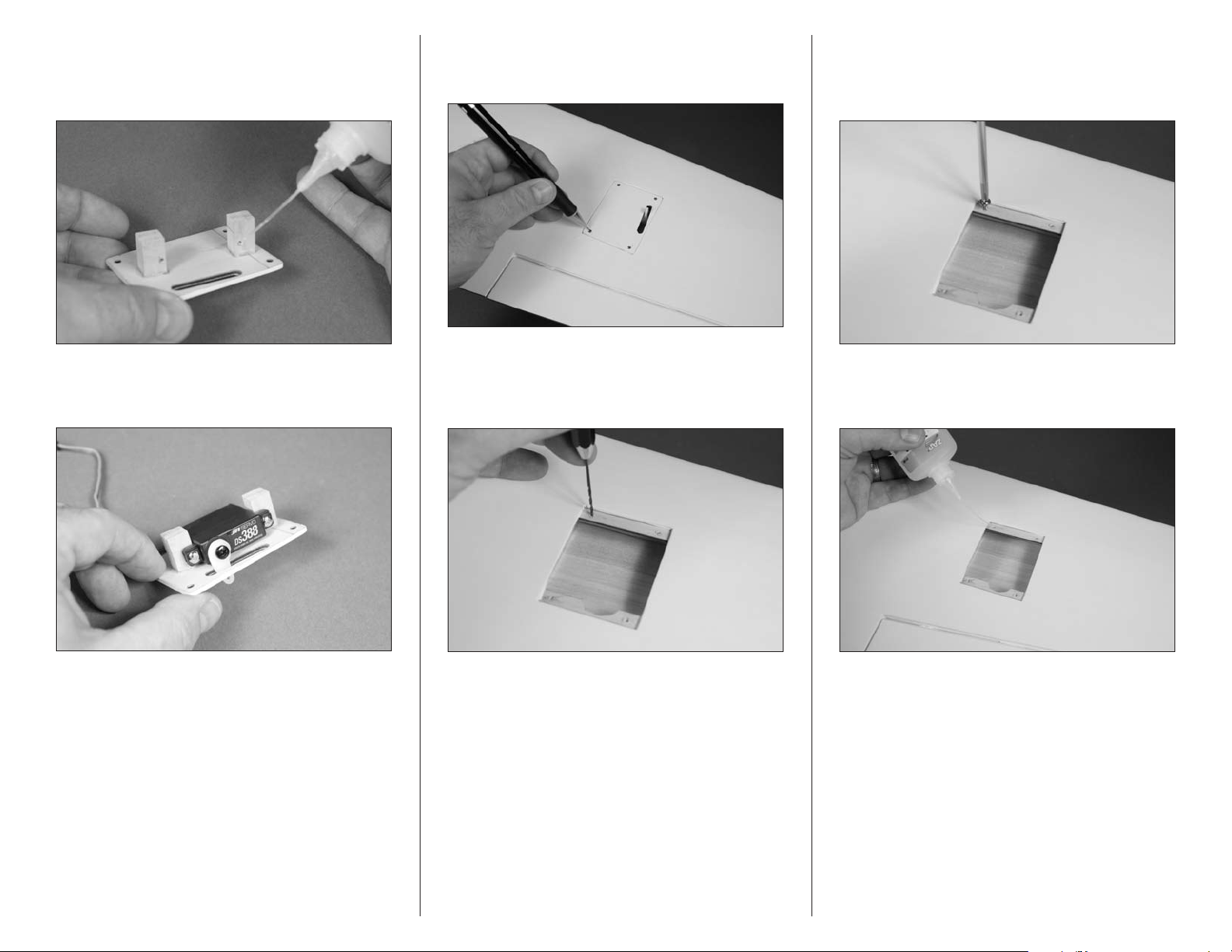
16. Apply 2–3 drops of thin CA in each hole drilled.
Also saturate the front and rear of the block using thin CA to
harden the block. This will help keep the block from splitting
when the servo mounting screws are installed.
17. Use the screws included with the servo and a #1
Phillips screwdriver to attach the servo to the mounting
blocks.
18. Fit the aileron servo and cover to the wing. Use
a pencil to transfer the four positions for the servo cover
mounting screws onto the cover rails.
19. Remove the cover and servo from the wing. Use a
pin vise and 1/16-inch (1.5mm) drill bit to drill the four holes
for the cover mounting screws. Make sure not to accidentally
drill through the top of the wing.
20. Use a #1 Phillips screwdriver to run a 2mm x 8mm
self-tapping screw in each of the holes to cut threads in the
surrounding wood. Remove the screw before proceeding to
the next step.
21. Apply 2–3 drops of thin CA in each hole to harden
the surrounding wood. This will help prevent the screws
from vibrating loose.
24 Hangar 9 Sundowner 36 ARF
Page 25
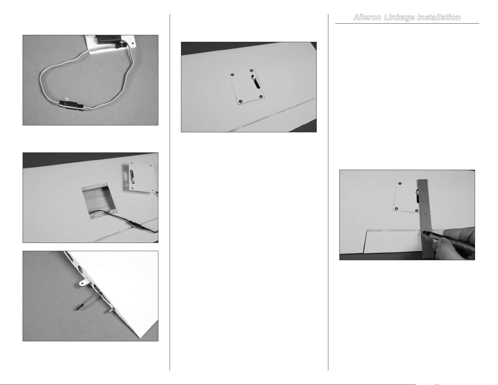
22. Secure a 6-inch (152mm) servo extension to the
servo lead using string or a commercially available connector.
23. Use music wire or string to pull the servo
extension through the wing.
24. Secure the servo cover and servo to the wing
using a #1 Phillips screwdriver and four 2mm x 8mm selftapping screws.
23. Repeat steps 8 through 24 to install the remaining
aileron and aileron servo.
24. Remember to turn off the radio system at this time to
avoid running the battery down.
Aileron Linkage Installation
Required Parts
Nylon clevis (2) Receiver battery
Transmitter Receiver
2-inch (52mm) pushrod (2)
2mm x 12mm machine screw (4)
Nylon control horn with backplate (2)
Wing panel with aileron (right and left)
Required Tools and Adhesives
Phillips screwdriver: #1 Felt-tipped pen
Pin vise Drill bit: 5/64-inch (2mm)
Ruler
1. Use a ruler and a felt-tipped pen to make a small
mark on the aileron used for positioning the aileron control
horn. Align the ruler so it is resting against the outside edge of
the servo horn and is perpendicular to the aileron hinge line.
25Hangar 9 Sundowner 36 ARF
Page 26
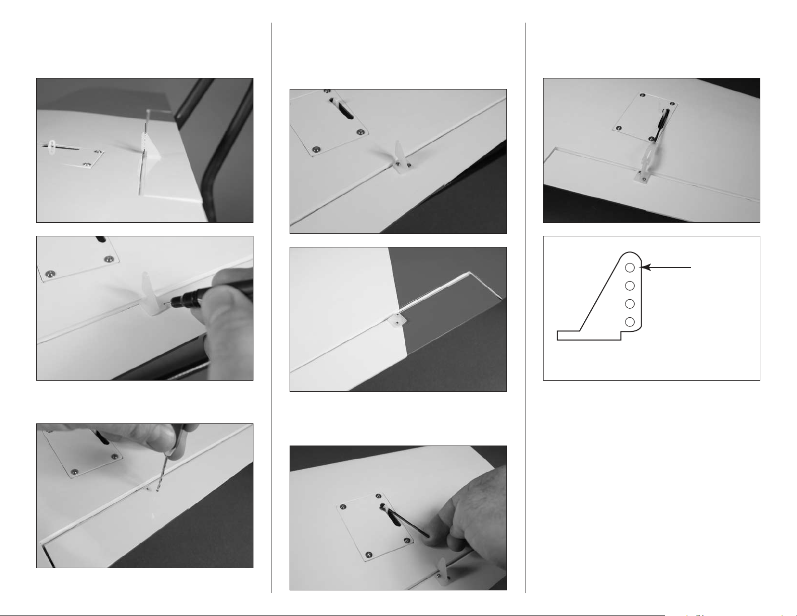
2. Center the control horn on the mark made in the
Drawing not to scale
Attach clevis
previous step. The holes in the control horn will align with
the hinge line. Use a felt-tipped pen to mark the locations for
the two mounting screws on the aileron.
4. Use two 2mm x 12mm machine screws and the
control horn backplate to secure the control horn to the
aileron. Use a #1 Phillips screwdriver to tighten the screws.
Be careful not to crush the underlying wood when installing
the control horn.
6. With the radio on and the aileron servo centered,
thread the nylon clevis on the pushrod. Thread the clevis
on enough so the aileron is centered when the clevis is
connected to the outer hole of the control horn shown below.
3. Use a pin vise and a 5/64-inch (2mm) drill bit to drill
the holes for the control horn mounting screws.
5. Insert the Z-bend of the 2-inch (52mm) linkage in
the hole of the servo arm that was enlarged in the previous
section of this manual.
7. Check the operation of the aileron using the radio
system. If you find the pushrod or servo horn binding on the
servo cover, use a hobby knife with a #11 blade to slightly
trim the cover to eliminate this binding.
8. Repeat steps 1 through 7 to install the remaining
aileron control horn and linkage.
9. Remember to turn off the radio system at this time to
avoid running the batteries down.
26 Hangar 9 Sundowner 36 ARF
Page 27
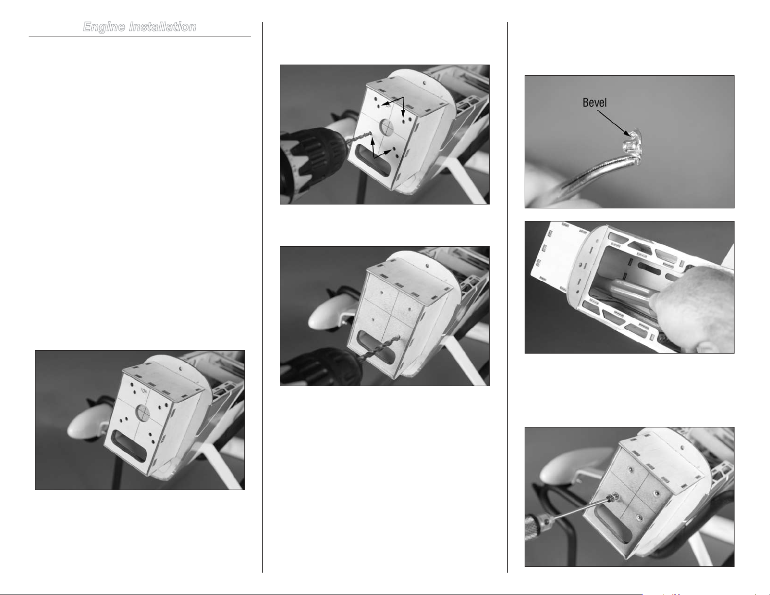
Engine Installation
Required Parts
Fuselage assembly Engine mount (right and left)
3mm blind nut (4) 3mm locknut (4)
3mm lock washer (4) 3mm washer (12)
Engine
Plywood engine mount template
3mm x 20mm socket head screw (4)
3mm x 25mm socket head screw (4)
Required Tools and Adhesives
Drill Hobby knife with #11 blade
Pencil Tapered reamer
Side cutter Thin CA
Hex wrench: 2.5mm Nut driver: 5.5mm
Ruler Medium CA
Drill bit: 1/8-inch (3mm), 3/16-inch (5mm)
Note: If you are preparing your model for
EP flight, skip to page 36 and begin with
the section “Motor Installation.”
2. Use a drill and 1/8-inch (3mm) drill bit to drill the four
holes for mounting the engine. Use the inner set of holes as
shown below.
3. Use a drill and 3/16-inch (5mm) drill bit to enlarge the
holes in the firewall.
4. Note there is a slight bevel where the blind nut
contacts the back side of the firewall. Use a hobby knife
or tapered reamer to bevel the inside of the holes to fit the
bevel of the blind nut.
1. Locate the plywood engine mount template. The
template will fit into the recess of the firewall. If not, lightly
sand the edges of the template so it fits into position.
5. Install the blind nuts into the back side of the firewall.
Use a 3mm x 20mm socket head bolt and 3mm washer
to draw the prongs of the blind nut into the firewall, fully
seating them. Use a 2.5mm hex wrench when tightening the
socket head bolts.
27Hangar 9 Sundowner 36 ARF
Page 28
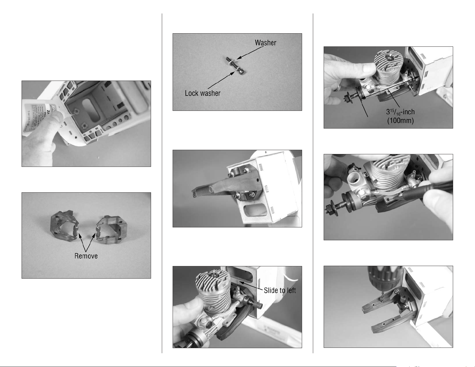
Hint: Use a drop of medium CA to attach the
blind nut to your finger so it can be installed
easily. Make sure it is not glued too well as
it may become difficult to break free.
6. Apply 2–3 drops of thin CA to each of the prongs of
the blind nuts to secure their locations. Be careful not to get
CA in the threads of the blind nut as it will make installing
the screws difficult.
7. Use side cutters to remove the portion of the engine
mount as shown in the photo.
8. Prepare four 3mm x 20mm socket head screws by
sliding a 3mm lock washer and 3mm washer on each screw.
9. Place the engine mount rails on the firewall as shown.
Use the four 3mm x 20mm machine screws to hold the
mount in position. Do not tighten the screws, as the mount
will need to be adjusted for your particular engine.
11. Position the engine so the face of the drive washer
is 315/16-inch (100mm) forward of the firewall. Make sure to
measure from the firewall where the mount is located, not
the edges of the engine box.
12. Use a pencil to mark the locations for the four engine
mounting screws on the engine mount.
10. Place the engine between the mount and slide the
nylon mounting beams tight against the engine case. Slide
the engine and mount as far to the left as possible, as this will
center the propeller shaft with the cowling when it is installed.
28 Hangar 9 Sundowner 36 ARF
13. Use a drill and 1/8-inch (3mm) drill bit to drill the
holes for the engine mounting screws.
Page 29
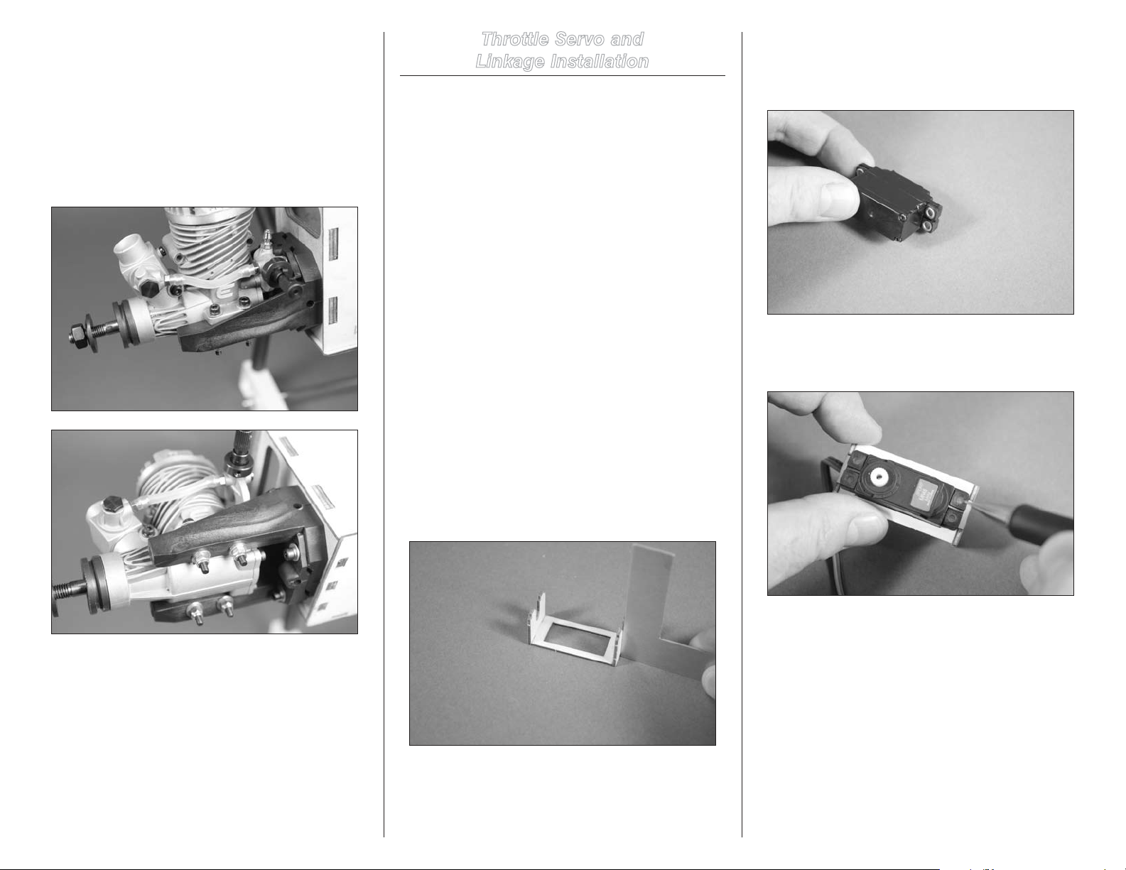
Hint: Use a drill press to drill the holes
for the engine mounting bolts so they
are nice and straight in the mount.
14. Use four 3mm x 25mm socket head bolts, eight 3mm
washers and the four 3mm lock nuts to secure the engine to
the mounting rails. Use a 2.5mm hex wrench and 5.5mm nut
driver to tighten the hardware. Also remember to tighten the
screws that secure the mount to the firewall using a 2.5mm
hex wrench.
Throttle Servo and
Linkage Installation
Required Parts
Fuselage assembly Servo with hardware
Plywood servo tray Pushrod connector
1.5mm knurled nut 1.5mm washer
Transmitter Receiver
Receiver battery
3mm x 4mm socket head screw
7
13
/8-inch (352mm) throttle pushrod
3
8
/4-inch (220mm) pushrod tube
Plywood servo tray support (2)
Required Tools and Adhesives
Pin vise Square
Medium CA Thin CA
Threadlock Pencil
Medium grit sandpaper Phillips screwdriver: #1
Ruler Side cutters
Pin vise Hex wrench: 2.5mm
Drill bit: 1/16-inch (1.5mm), 7/64-inch (2.5mm)
2. Prepare the throttle servo by installing the rubber
grommets and brass eyelets that were included with the
servo. Use a #1 Phillips screwdriver to remove the servo
horn from the servo.
3. Test fit the servo in the throttle servo tray. Use a pencil
to transfer the locations of the servo mounting screws on
the servo tray.
1. Use medium CA glue to assemble the throttle servo
tray using the plywood servo tray and two servo tray
supports. Make sure the supports are square to the tray
before the CA cures.
29Hangar 9 Sundowner 36 ARF
Page 30
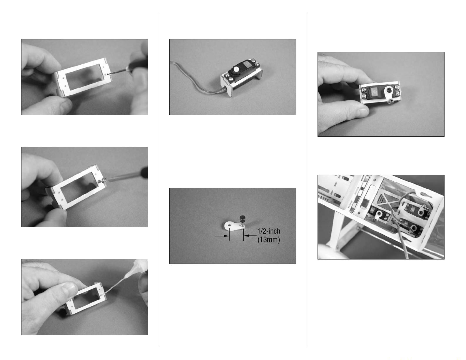
4. Remove the servo from the servo tray. Use a pin vise
and 1/16-inch (1.5mm) drill bit to drill the holes for the
servo mounting screws.
7. Secure the servo in the servo tray using the screws
provided with the servo and a #1 Phillips screwdriver. Route
the servo lead through the notch in the servo tray support.
9. Use the transmitter to center the throttle servo. Center
the throttle stick and trim, then install the servo horn as
shown. This will provide equal throw for both full- and
closed-throttle. Use a #1 Phillips screwdriver and the screw
removed from the servo to secure the horn on the servo.
5. Use a #1 Phillips screwdriver to run a servo mounting
screw in each of the holes to cut threads in the surrounding
wood. Remove the screw before proceeding to the next step.
6. Apply 2–3 drops of thin CA in each hole to harden the
surrounding wood. This will help prevent the screws from
vibrating loose.
Note: Always use threadlock on metal-to-metal
fasteners to prevent them from vibrating loose.
8. Attach the pushrod connector to the servo horn using
a 1.5mm knurled nut, 3mm x 4mm socket head machine
screw and 1.5mm washer. Position the connector so it is 1/2inch (13mm) from the center of the horn. Use side cutters to
remove any unused arms from the horn so they don’t interfere
with the operation of the throttle servo.
10. Use medium CA to glue the throttle servo tray in the
fuselage. Use care not to glue the servo lead in case the
servo must be removed later. Note that the output of the
servo faces to the rear of the fuselage.
30 Hangar 9 Sundowner 36 ARF
Page 31
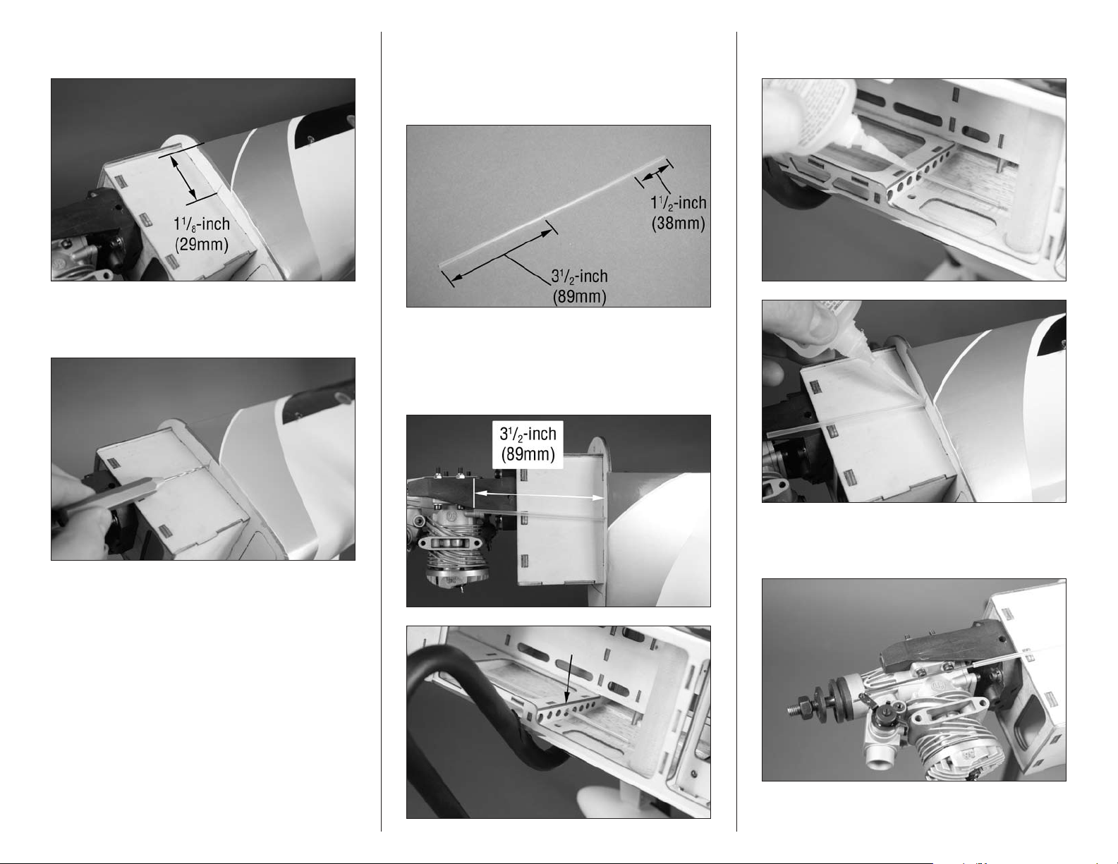
11. Use a ruler to measure down 1
the front edge of the fuselage in the location shown.
1
/8-inch (29mm). Mark
12. Use a pin vise and 7/64-inch (2.5mm) drill bit to drill
a hole as close to the engine box as possible for the throttle
pushrod tube.
13. Use medium grit sandpaper to sand a 1/2-inch
(13mm) wide area on the pushrod tube that is 11/2-inch
(38mm) and 31/2-inch (89mm) from the ends of the tube.
This provides an area for the CA to adhere to when the tube
is glued in place.
14. Slide the tube into the fuselage with the 1
(38mm) first. Note the position of the tube inside the
fuselage as it passes through the formers. Position the tube
so 31/2-inch (89mm) of the tube is exposed forward of the
fuselage as shown.
1
/2-inch
15. Apply 2–3 drops of medium CA where the pushrod
tube passes through the formers to secure its location.
16. Attach the Z-bend in the pushrod to the outer hole of
the carburetor arm. The wire will pass through the tube and
into the fuselage.
Hint: Remove the carburetor to make the
installation of the pushrod wire easier.
31Hangar 9 Sundowner 36 ARF
Page 32

Note: Always use threadlock on metal-to-metal
fasteners to prevent them from vibrating loose.
17. Move the carburetor to the open position. Use the
radio system to move the throttle servo to the open position.
Insert the wire through the pushrod connector and secure
it with the 3mm x 4mm socket head machine screw. Use a
2.5mm hex wrench to tighten the screw.
18. Check the operation of the throttle to make sure the
carburetor moves from open to closed. You may need to
make adjustments at the radio so the servo does not bind at
either extreme.
19. Remember to turn off the radio system at this time to
avoid running the batteries down.
Fuel Tank Installation
Required Parts
Fuselage assembly Fuel tank
Rubber stopper Stopper plate, small
Stopper plate, large Clunk
Mixing stick (not included)
Fuel tubing (not included)
Aluminum tube, 2-inch (51mm)
Aluminum tube, 2
Fuel tubing, 4
3mm x 30mm self-tapping screw
Tools and Adhesives
Ruler Phillips screwdriver: #1
Razor saw Medium CA
Hobby knife with #11 blade
1. Remove the material so two of the three holes in the
stopper pass completely through, as well as the center hole
for the screw that will secure the stopper. Use a hobby knife
and #11 blade for this procedure.
3
/4-inch (70mm)
1
/2-inch (115mm)
2. Carefully bend the 2
a 45-degree angle. This will place it close to the top of the
tank when installed.
Hint: Use a solid round object such as a
paint can to bend the tube around to help
reduce the chance of kinking the tubing.
3
/4-inch (70mm) aluminum tube at
3. Slide the aluminum tube from the previous step
through the smaller stopper plate. Note that the boss for
the screw will face toward the bend in the tube. The tube is
then inserted in the stopper from the smaller or back of the
stopper. Leave 5/8-inch (16mm) of the tube forward of the
stopper.
32 Hangar 9 Sundowner 36 ARF
Page 33
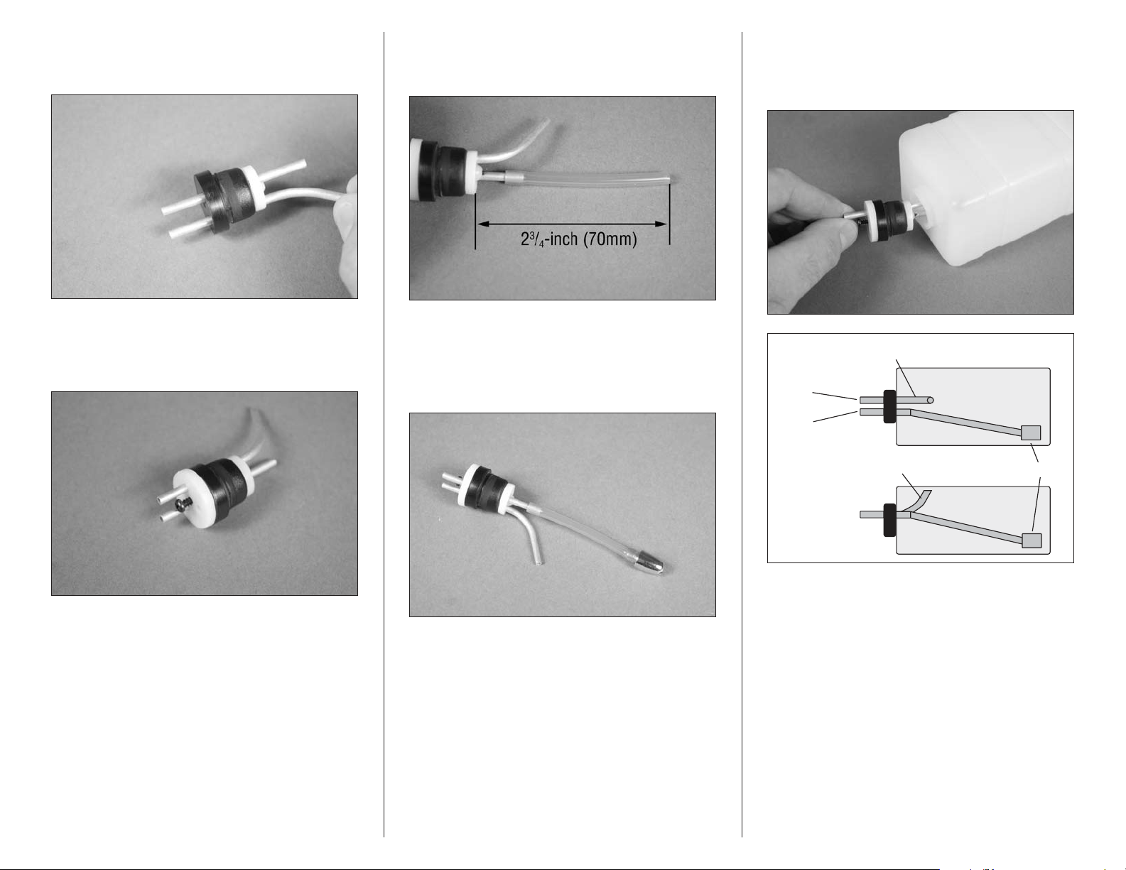
4. Slide the 1
Clunk
Vent Line
Top View
Side View
Vent Line (faces top of fuselage)
To Muffler
To Carburetor
the stopper. Position the front of the tube even with the bent
tube as shown.
7
/8-inch (48mm) aluminum tube through
6. Attach the 4
straight tube. Use a hobby knife to trim the length of the tube
to a length of 23/4-inch (70mm) as shown in the photo below.
1
/2-inch (115mm) piece of fuel tubing to the
8. Insert the stopper assembly into the fuel tank. Make
sure the vent line faces to the top of the tank as shown.
Note that the hole in the tank is off-center. The hole for the
stopper will be closer to the bottom of the tank.
5. Slide the larger stopper plate over the tubing at the
front. Start the 3mm x 30mm self-tapping screw using a
#1 Phillips screwdriver. The screw only needs to be in far
enough to keep the large stopper plate from falling off.
Note: Check the ends of the aluminum tubes
for sharp edges. If any sharp edges are found,
remove them before installing the fuel tubing
7. Attach the clunk to the end of the tubing as shown.
33Hangar 9 Sundowner 36 ARF
Page 34
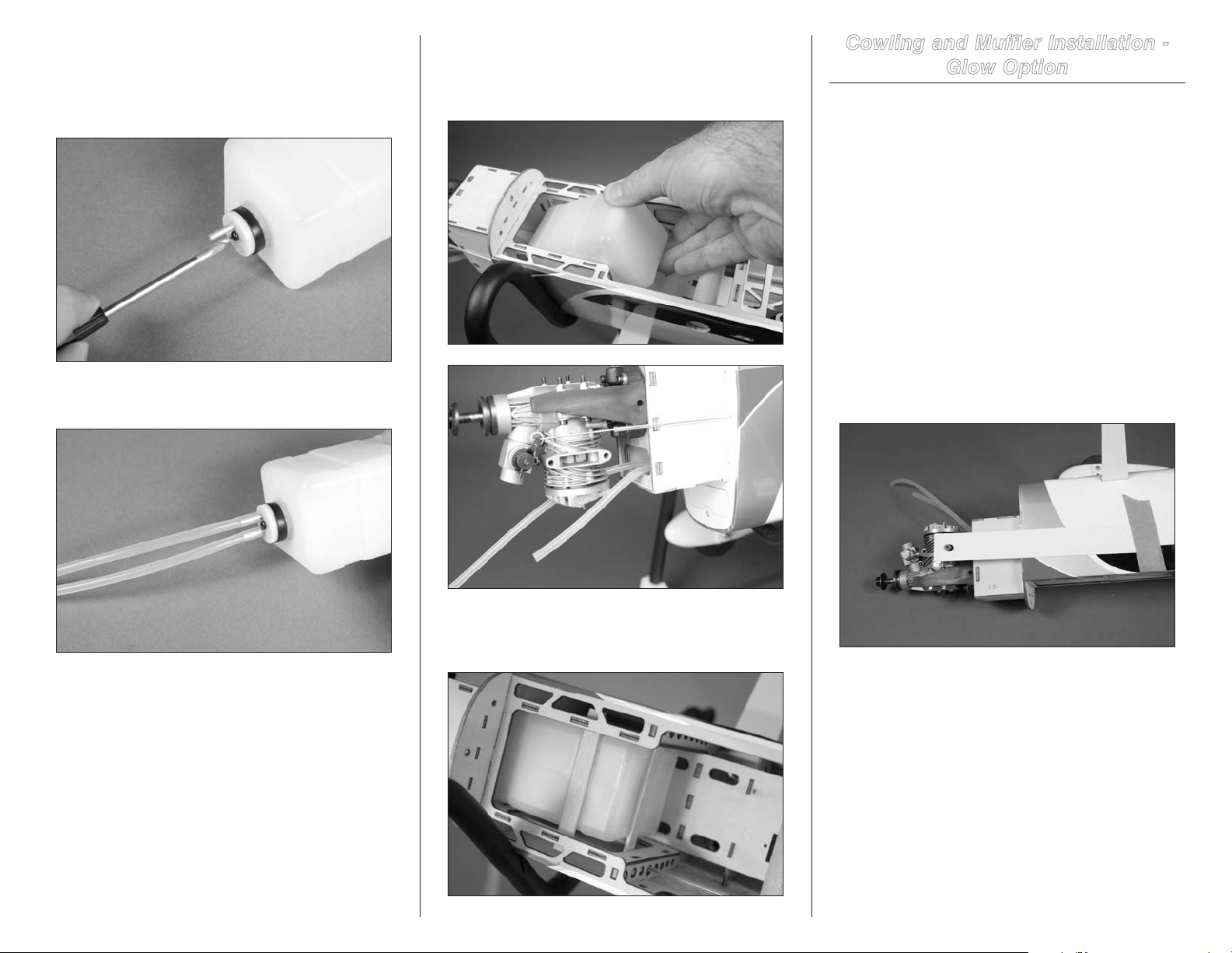
9. Use a #1 Phillips screwdriver to tighten the 3mm x
30mm self-tapping screw that secures the stopper in the
tank. Don’t over-tighten the screw as you could damage
the fuel tank. It needs to be tight enough to create a seal
between the tank and stopper.
10. Slide the fuel tubing (not included) on the aluminum
tubes outside the tank.
11. Slide the fuel tank into the fuselage. Guide the lines
from the tank through the hole in the firewall. Slide the tank
in only as far is it will easily slide. Do not force the fuel tank
forward and damage the fuel lines.
Cowling and Muffler Installation -
Glow Option
Required Parts
Fuselage assembly Muffler with hardware
Cowling 3mm washer (2)
Propeller (not included) Spinner assembly
3mm x 10mm socket head screw (2)
Tools and Adhesives
Low-tack tape Rotary tool
Sanding drum Hobby scissors
Hex wrench: 2.5mm Felt-tipped pen
Card stock
1. Use hobby scissors to cut pieces of card stock
to locate the needle valve and any other items that may
protrude through the cowling. Use low-tack tape to secure
the card stock to the fuselage.
12. Use a razor saw to cut two mixing sticks to a length
of 3 inches (76mm). Use these and medium CA to secure
the tank in the fuselage.
Important: We recommend using two colors of
tubing on the tank: red on the vent line and the
green on the line from the clunk. If a single color
is used, make sure to mark them so they can be
identified when the tank is inside the fuselage.
34 Hangar 9 Sundowner 36 ARF
Note: Because of the shape of the cowl you may not
be able to easily locate all the items using card stock.
Page 35
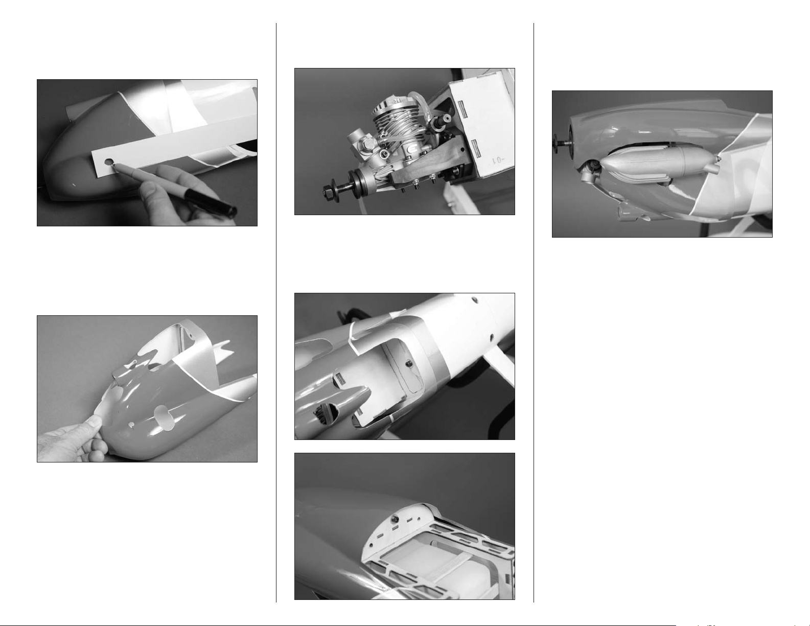
2. Slide the cowling on the fuselage until the inner
support of the cowling contacts the fuselage. Use a felttipped pen to transfer the locations from the card stock to
the cowling.
3. Use hobby scissors and a rotary tool with a sanding
drum to remove the material necessary to fit the cowl over
the engine. Work slowly, removing only small amounts from
the cowl at a time. Test fit the cowling periodically to make
sure it is fitting properly. Create a small opening for the
muffler at this time as well.
4. Connect the line from the clunk to the carburetor.
Leave the line long so it can be removed through the cowl
using hemostats.
5. Attach the cowl to the fuselage using two 3mm x
10mm socket head machine screws and two 3mm washers.
The lower screw is installed from the inside of the cowl,
while the upper screw is installed inside the fuselage. Use a
2.5mm hex wrench to tighten the screws.
6. Attach the muffler to the engine using the hardware
provided with the engine. Make sure there is clearance
around the muffler so it does not damage the cowl when it
gets hot. Connect the line from the vent on the fuel tank to
the muffler.
7. Attach the propeller and spinner to the engine. Follow
the instructions provided with the engine to make sure the
propeller is secure.
35Hangar 9 Sundowner 36 ARF
Page 36
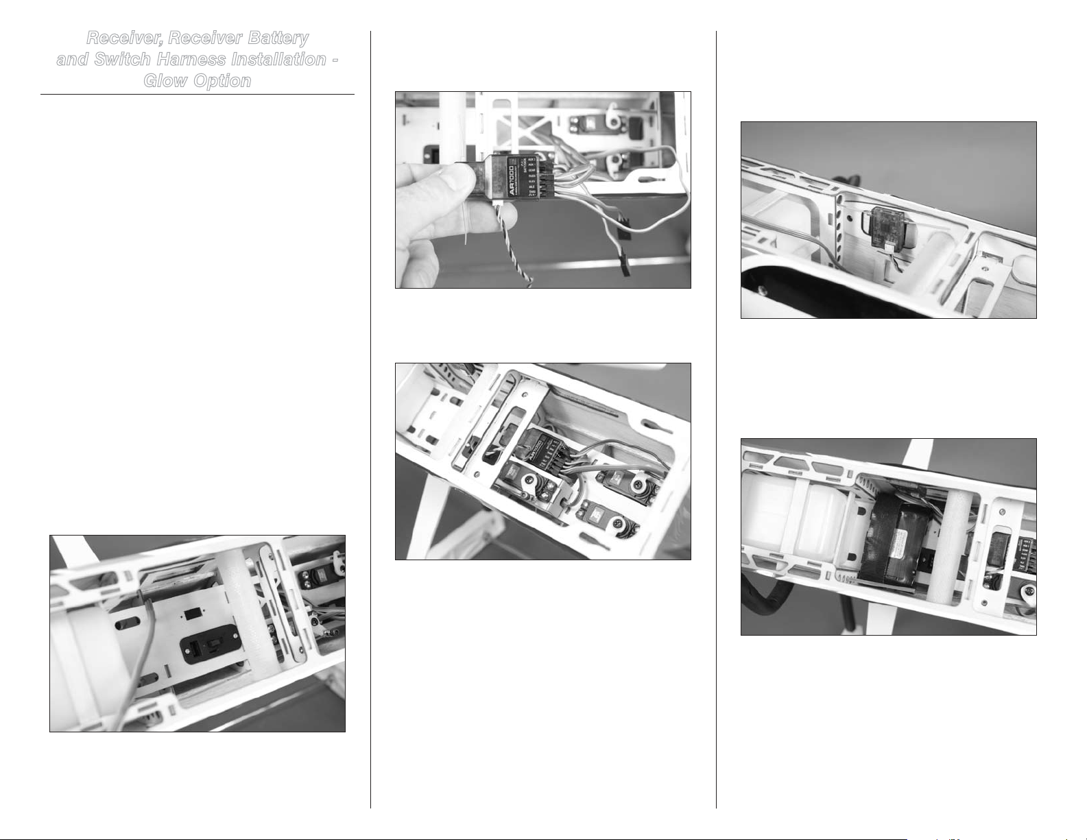
Receiver, Receiver Battery
and Switch Harness Installation -
Glow Option
Required Parts
Fuselage assembly Receiver battery
Receiver Switch harness with hardware
Hook and loop tape (not included)
Hook and loop strap (not included)
Foam rubber (not included)
Y-harness (1-channel ailerons)
3-inch (76mm) servo extension (2) (2-channel ailerons)
Required Tools and Adhesives
Phillips screwdriver: #1
Note: The ailerons can be connected to the
receiver using a Y-harness, utilizing the single
aileron channel. They can also be connected
to the aileron and an auxiliary channel, but you
will require the use of a computer radio to mix
the auxiliary channel to the aileron channel.
1. Mount the switch in the fuselage using the hardware
provided with the switch and a #1 Phillips screwdriver. Note
there are multiple locations available, depending on your
switch selection. Make sure to route the leads from the
switch where they can be accessed for the connections to
the receiver and receiver battery.
2. Connect the leads from the rudder, elevator and throttle
servos to the receiver. Also connect the switch harness and
extensions for the ailerons at this time.
3. Use hook and loop tape to secure the receiver in the
fuselage. Make sure to route the leads so they don’t interfere
with the operation of the servos.
4. Mount the remote receiver in the fuselage away from
the main receiver using hook and loop tape. Make sure
to orient the antenna on the remote receiver in a different
direction than those on the main receiver for the best
reception from your radio system.
5. Use a hook and loop strap to secure the receiver
battery in the fuselage. Make sure to place a piece of
foam rudder between the receiver battery and radio tray
to isolate the battery from vibrations. Secure the receiver
battery lead to the switch harness lead so it does not
disconnect accidentally.
36 Hangar 9 Sundowner 36 ARF
Page 37
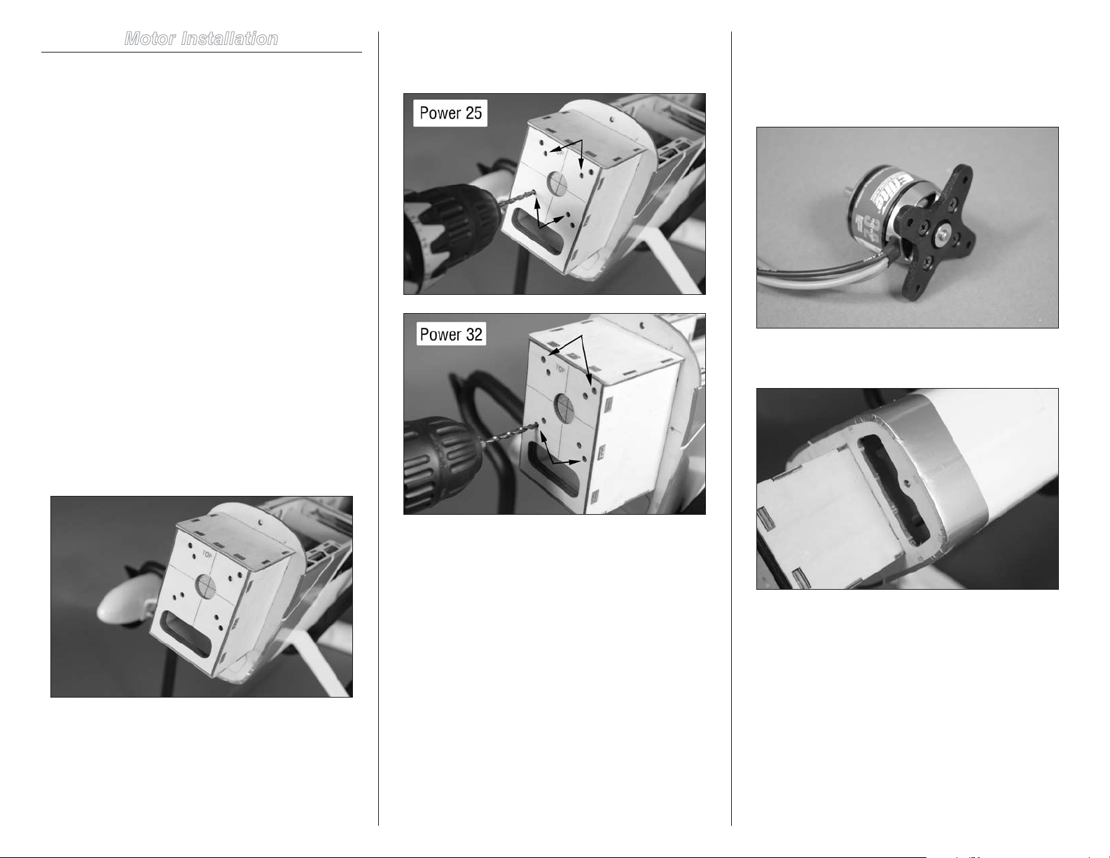
Motor Installation
Required Parts
Fuselage assembly
3mm lock nut (4) 3mm washer (8)
Electronic speed control
Motor with hardware and X-mount
Aluminum stand-off, 3/4-inch (22mm) (4) (Power 25)
Aluminum stand-off, 1
Plywood engine mount template
3mm x 30mm socket head screw (4) (Power 25)
3mm x 35mm socket head screw (4) (Power 32)
Hook and loop tape (not included)
Required Tools and Adhesives
Drill Needle nose pliers
Hemostats Threadlock
Ball driver: 2.5mm Nut driver: 5.5mm
Hobby knife with #11 blade
Drill bit: 1/8-inch (3mm)
Phillips screwdriver: #2
1. Locate the plywood engine mount template. The
template will fit into the recess of the firewall. If not, lightly
sand the edges of the template so it fits into position.
1
/16-inch (27mm) (4) (Power 32)
2. Use a drill and 1/8-inch (3mm) drill bit to drill the four
holes for mounting the engine. Use the inner set of holes for
the Power 25, the outer set of holes for the Power 32.
Note: Always use threadlock on metal-to-metal
fasteners to prevent them from vibrating loose.
3. Use the hardware provided with the motor to attach the
X-mount. Use a #2 Phillips screwdriver to tighten the screws.
4. Use a hobby knife and a #11 blade to remove the plywood
to access the fuselage for the speed control installation.
Note: The following steps will show the recommended
Power 32 motor installation. The Power 25
follows the same procedure, but will mount in
the holes drilled in step 2 for the Power 25.
37Hangar 9 Sundowner 36 ARF
Page 38
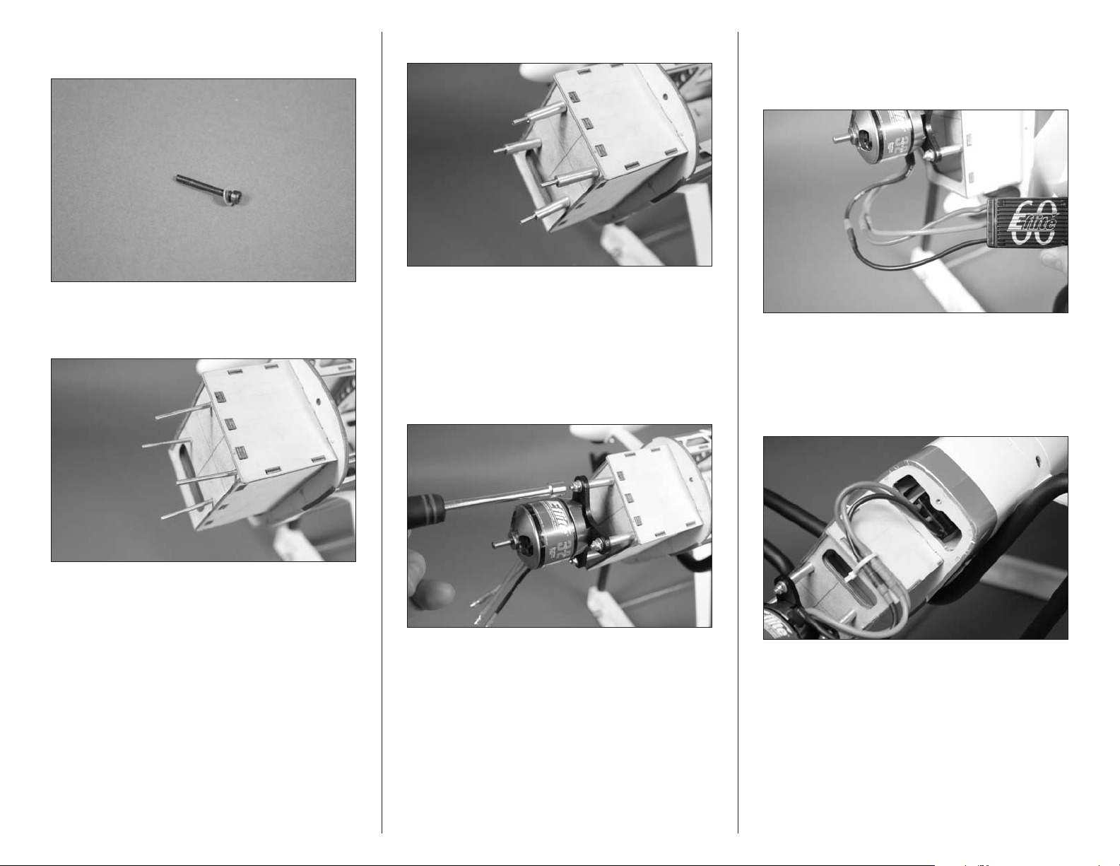
5. Prepare four 3mm x 35mm socket head screws by
sliding a 3mm washer on each screw.
7. Slide an aluminum stand-off on each of the screws.
9. Connect the leads from the motor to the speed control.
If you are using the recommended equipment, matching
the colored wires between the speed control and motor will
result in the motor rotating in the correct direction.
6. Slide the screws through the firewall from inside the
fuselage. You may need to use needle nose pliers or hemostats
to hold the screws while inserting them in the fuselage.
Note: The Power 32 will require four 11/16-inch (27mm)
aluminum standoffs. Use four 3/4-inch (22mm) aluminum
standoffs for the Power 25 installation.
8. Attach the motor to the firewall using four 3mm
washers and four 3mm lock nuts. Use a 2.5mm ball driver
to hold the screws from the inside of the fuselage while
tightening the nuts with a 5.5mm nut driver.
10. Use hook and loop tape (not included) to secure the
speed control inside the fuselage. Make sure to guide the
leads for the battery, switch and connection to the receiver
into the fuselage where they can be accessed later. The
speed control will attach to the inside of the fuselage, not to
the underside of the battery tray.
Note: Drill a 1/8-inch (3mm) hole in the
bottom of the motor box and use a tie wrap
(not included) to secure the wires so they don’t
interfere with the operation of the motor.
38 Hangar 9 Sundowner 36 ARF
Page 39
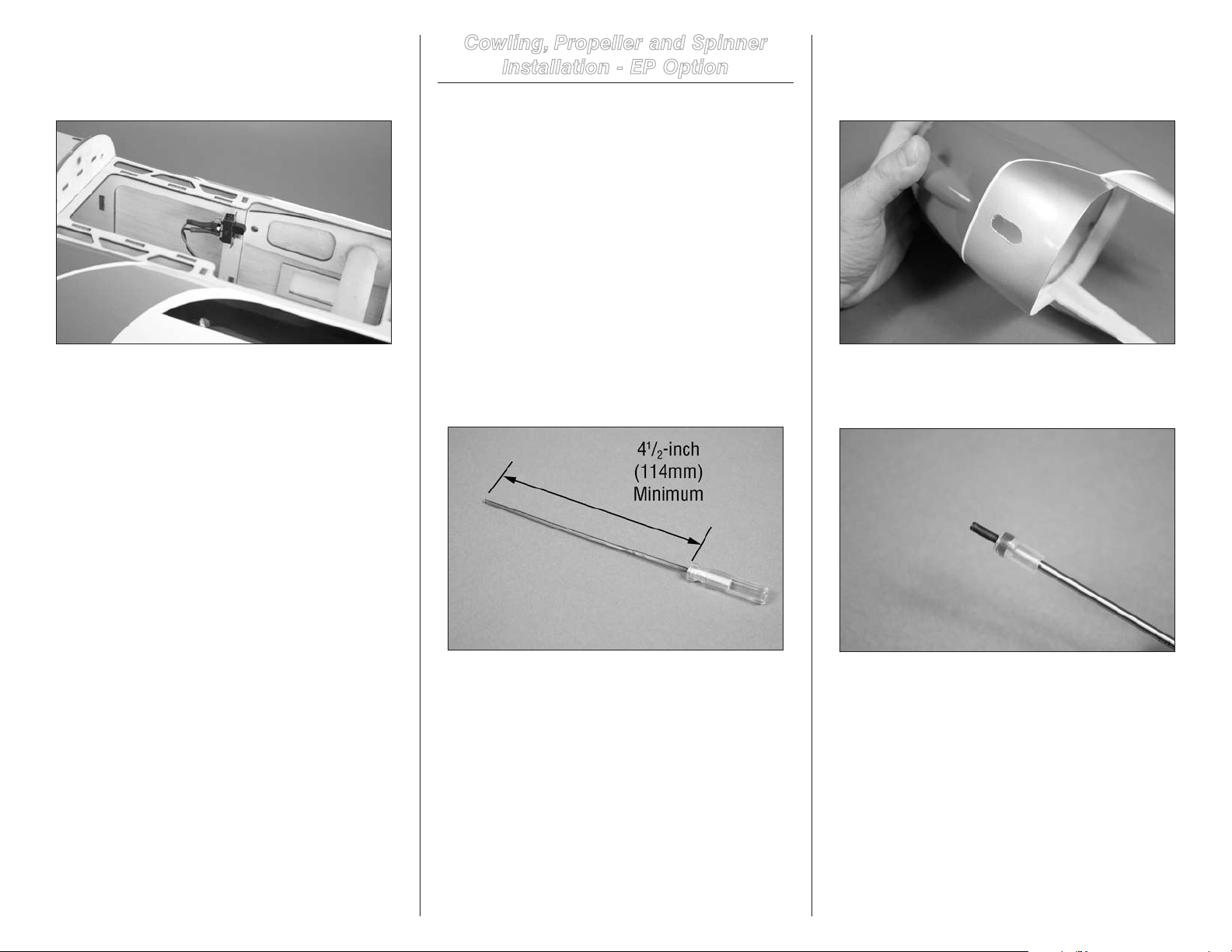
11. Secure the switch in the fuselage using a small
amount of silicone adhesive or two-sided tape. Position the
switch so it does not interfere with the installation of the
motor battery.
Cowling, Propeller and Spinner
Installation - EP Option
Required Parts
Fuselage assembly Cowling
3mm washer Fuel tubing (not included)
Propeller (not included)
Spinner assembly (not included)
3mm x 10mm socket head screw (2)
Required Tools and Adhesives
Ruler Ball driver: 2.5mm
Ball driver: 2.5mm Hobby scissors
Rotary tool Sanding drum
Open end wrench: 10mm Hobby knife with #11 blade
2. (Optional) Use hobby scissors and a rotary tool to
make a 3/8-inch x 3/4-inch (9mm x 19mm) slot in the
bottom of the cowl to access the lower mounting screw if
your ball driver is less than 41/2 inches (114mm) in length.
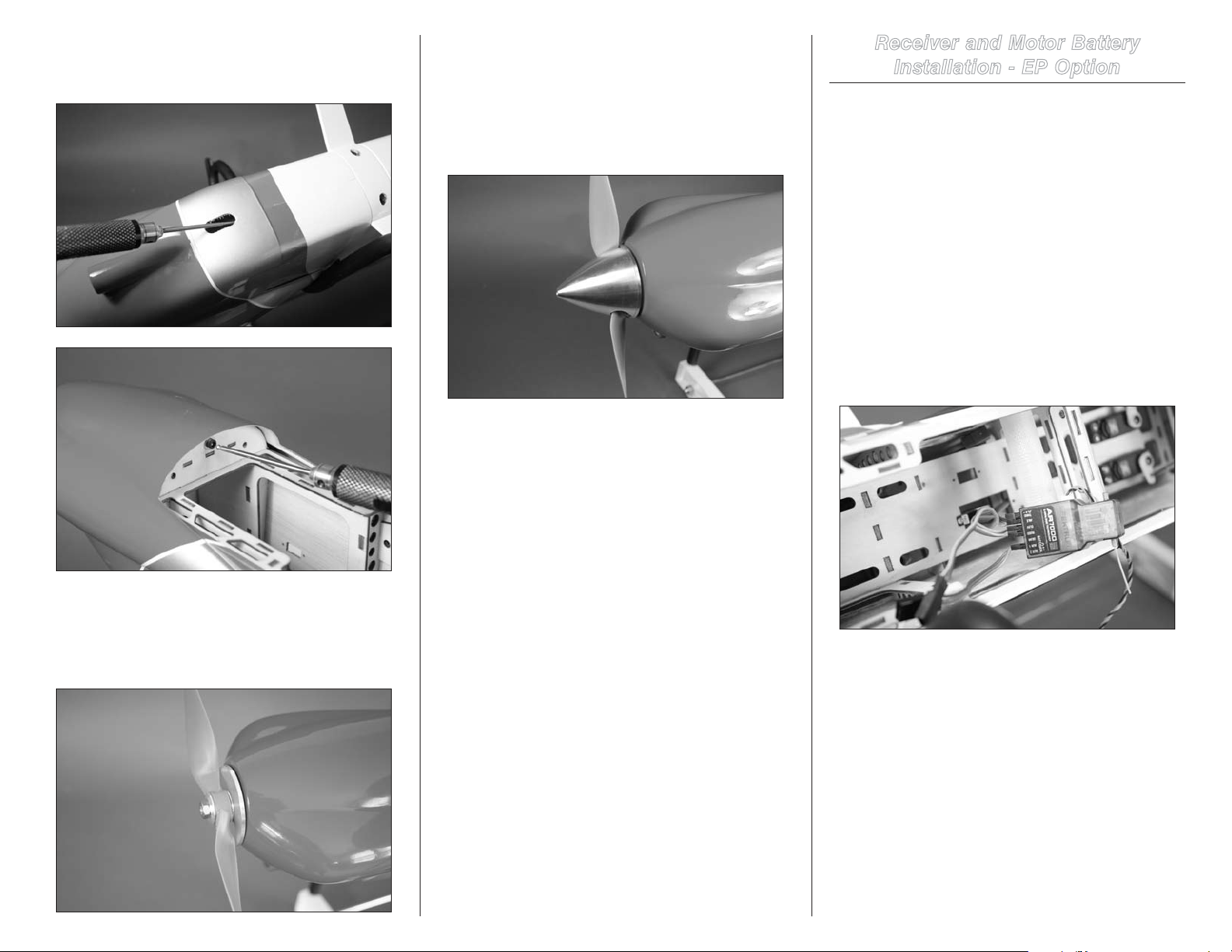
1. Check the length of your 2.5mm ball driver. If it is not
at least 41/2 inches (114mm), you will need to make a small
access opening in the cowl as shown in the next step.
3. To make the installation of the lower cowl mounting
screw easier, use a 1/2-inch (13mm) piece of fuel tubing to
keep the screw attached to the ball driver as shown.
39Hangar 9 Sundowner 36 ARF
Page 40
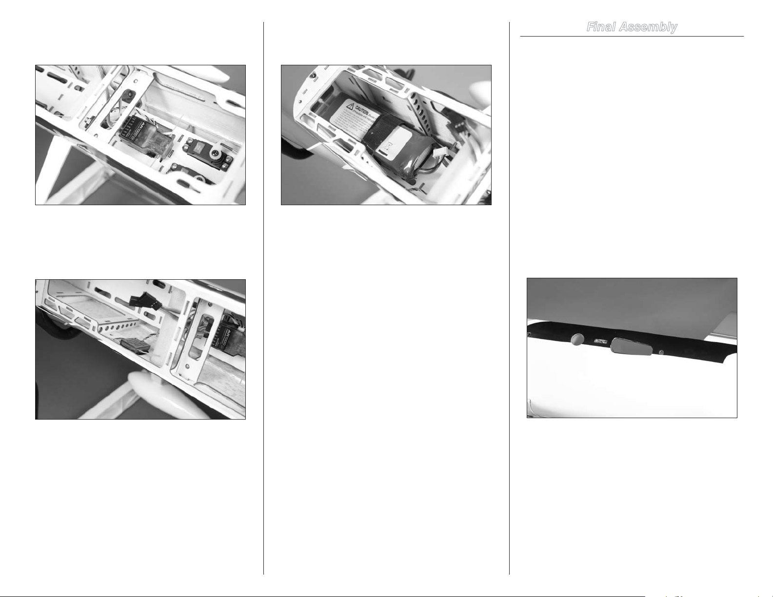
4. Slide the fuselage into position on the front of the
fuselage. Use two 3mm x 10mm socket head screws and
two 3mm washers to secure the cowl to the fuselage.
Important: Always balance the propeller before
securing it to the motor. An unbalanced propeller
can transmit vibrations into the motor or airframe,
causing damage or even failure of these components.
6. Use a 3/32-inch hex wrench to tighten the screw
securing the spinner cone to the backplate assembly.
Receiver and Motor Battery
Installation - EP Option
Required Parts
Fuselage assembly Receiver battery
Receiver Switch harness with hardware
Hook and loop tape (not included)
Hook and loop strap (not included)
Foam rubber (not included)
Y-harness (1-channel ailerons)
3-inch (76mm) servo extension (2) (2-channel ailerons)
Required Tools and Adhesives
Hobby scissors
1. Connect the leads from the rudder and elevator servos
to the receiver. Also connect the speed controller lead and
extensions for the ailerons at this time.
5. Fit the propeller and spinner backplate together.
Slide the assembly on the motor shaft so there is a slight
gap between the backplate and cowling. Use a 10mm
open-end wrench to tighten the nut that secures the
propeller to the spinner.
40 Hangar 9 Sundowner 36 ARF
Page 41
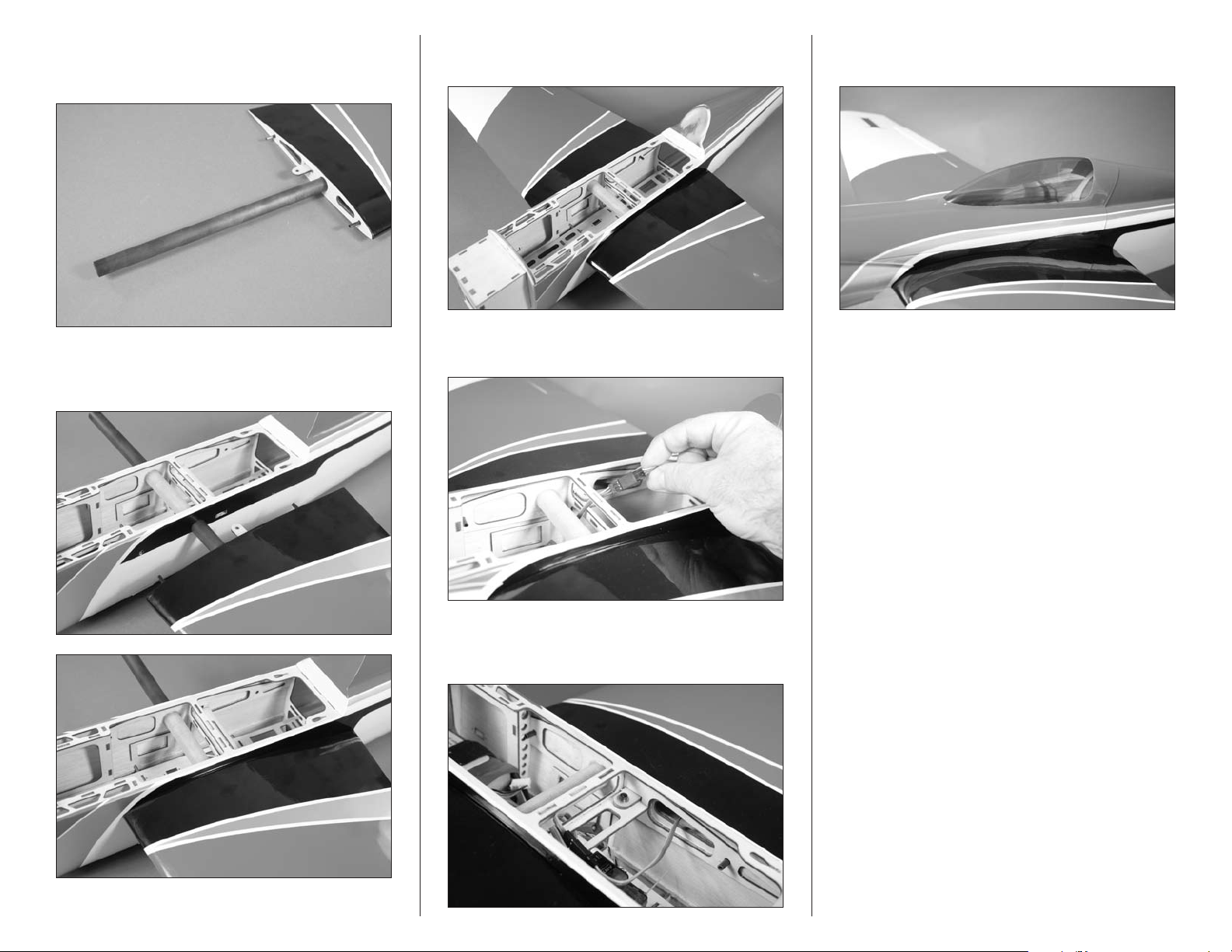
2. Use hook and loop tape to secure the receiver in the
fuselage. Make sure to route the leads so they don’t interfere
with the operation of the servos.
3. Mount the remote receiver in the fuselage away from
the main receiver using hook and loop tape. Make sure
to orient the antenna on the remote receiver in a different
direction than those on the main receiver for the best
reception from your radio system.
4. Secure the battery in the fuselage using hook and loop
straps. Use a piece of hook and loop tape along the bottom
of the battery to keep it from sliding on the battery tray.
Final Assembly
Required Parts
Fuselage assembly Wing panels (right and left
Canopy 3mm washer (2)
Carbon wing tube
3mm x 10mm socket head screw (2)
Required Tools and Adhesives
Ball driver: 2.5mm Hobby knife with #11 blade
Note: The ailerons can be connected to the
receiver using a Y-harness, utilizing the single
aileron channel. They can also be connected
to the aileron and an auxiliary channel, but you
will require the use of a computer radio to mix
the auxiliary channel to the aileron channel.
1. Use a hobby knife with a #11 blade to remove the
covering from the right and left side of the fuselage so the
aileron servo leads can pass into the fuselage.
41Hangar 9 Sundowner 36 ARF
Page 42
2. Locate the carbon wing tube. Slide the tube into one
of the wing panels. It will slide in easily, so do not force it
further than it will easily slide.
3. Slide the tube and wing panel into position on
the fuselage. The wing will fit tight against the fuselage
when installed.
4. Slide the remaining wing panel into position against
the fuselage.
5. Connect the leads from the aileron servos to the lead
(or Y-harness) from the aileron ports of the receiver.
7. Complete the airframe by placing the canopy back on
the fuselage.
6. Use two 3mm x 10mm socket head screws and two
3mm washers to secure the wings to the fuselage. Use a
2.5mm hex wrench to tighten the bolts securing the wing.
42 Hangar 9 Sundowner 36 ARF
Page 43
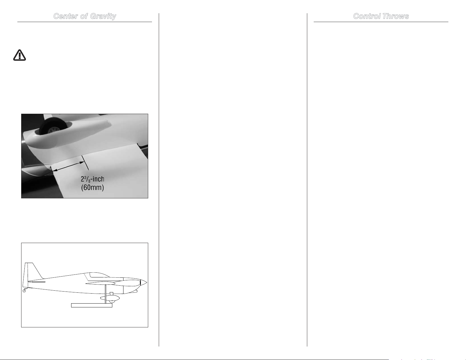
Center of Gravity
Balancing Stand
An important part of preparing the aircraft for flight is
properly balancing the model.
CAUTION: Do not inadvertently skip this step!
1. The recommended Center of Gravity (CG) location for
your model is 23/8-inch to 23/4-inch (60mm–70mm) back
from the leading edge of the wing as shown. We recommend
starting at the forward CG and making changes to suit your
preferred flying style. Mark the location of the CG on the
bottom of the wing with a felt-tipped pen.
3. You should find the CG to be very close with the
components installed as shown in this manual. If the nose
of your aircraft hangs low, add weight to the rear of the
aircraft. If the tail hangs low, add weight to the nose of the
aircraft. Stick-on weights are available at your local hobby
store and work well for this purpose.
Note: When using an EP power system, you can move
the motor battery to correct the Center of Gravity if it
is off. Mark the location of the battery on the battery
tray using a felt-tipped pen so it can be returned to
this position if it is removed from your model.
After the first flights, the CG position can be adjusted for
your personal preference.
Control Throws
1. Turn on the transmitter and receiver of your model.
Check the movement of the rudder using the transmitter.
When the stick is moved right, the rudder should also move
right. Reverse the direction of the servo at the transmitter if
necessary.
2. Check the movement of the elevator with the radio
system. Moving the elevator stick toward the bottom of the
transmitter will make the airplane elevator move up.
3. Check the movement of the ailerons with the radio
system. Moving the aileron stick right will make the right
aileron move up and the left aileron move down.
4. Use a ruler to adjust the throw of the elevator, ailerons
and rudder.
Aileron:
High Rate:
Up: 7/16-inches 11mm 30% Expo
Down: 11/32-inches 9mm 30% Expo
Low Rate:
Up: 9/32-inches 7mm 15% Expo
Down: 5/32-inches 4mm 15% Expo
2. When balancing your model, make sure it is assembled
and ready for flight. Support the plane upright at the marks
made on the wing with your fingers or a commercially
available balancing stand. This is the correct balance point
for your model.
Note: Measure the aileron throw from
the inboard edge of the aileron.
Elevator:
High Rate:
Up: 11/32-inches 9mm 25% Expo
Down: 11/32-inches 9mm 25% Expo
Low Rate:
Up: 3/16-inches 5mm 20% Expo
Down: 3/16-inches 5mm 20% Expo
Note: Measure the elevator throw from
the inboard edge of the elevator.
43Hangar 9 Sundowner 36 ARF
Page 44
Rudder:
High/Low Rate:
Right: 5/8-inches 16mm 15% Expo
Left: 5/8-inches 16mm 15% Expo
Note: Measure the rudder throw from the
bottom edge of the rudder at its widest point.
These are general guidelines measured from our own flight
tests. You can experiment with higher rates to match your
preferred style of flying.
Note: Travel Adjust, Sub-Trim and Dual Rates
are not listed and should be adjusted according
to each individual model and preference.
Note: We highly recommend re-binding the radio
system once all the control throws are set. This will
keep the servos from moving to their endpoints
until the transmitter and receiver connect.
Preight
Check Your Radio
Before going to the field, be sure your batteries are fully
charged per your radio’s instructions. Charge the transmitter
and motor battery for your airplane. Use the recommended
charger supplied with your particular radio system, following
the instructions provided with the radio. In most cases, the
radio should be charged the night before going out flying.
Before each flying session, be sure to range check your
radio. See your radio manual for the recommended
range and instructions for your radio system. Each radio
manufacturer specifies different procedures for their radio
systems. Next, run the motor. With the model securely
anchored, check the range again. The range test should not
be significantly affected. If it is, don’t attempt to fly! Have
your radio equipment checked out by the manufacturer.
Double-check that all controls (aileron, elevator, rudder and
throttle) move in the correct direction.
Check the radio installation and make sure all the control
surfaces are moving correctly (i.e., the correct direction and
with the recommended throws).
Check all the control horns, servo horns, and clevises to
make sure they are secure and in good condition.
Range Test Your Radio
Before each flying session, and especially with a new model,
it is important to perform a range check. It is helpful to have
another person available to assist during the range check. If
you are using a Spektrum transmitter, please refer to your
transmitter’s manual for detailed instructions on the range
check process.
Flight Hints and Tips
The takeoff and landing characteristics of this airplane are
actually very benign and any intermediate to advanced pilot
will be successful with the Sundowner 36. You can slow the
airplane nicely for landing (on your test flight take some time
before you have to land to slow the airplane at 2–3 mistakes
high to get the feel of the airplane as it approaches the stall).
The Sundowner 36 is designed to provide you with an
exhilarating flight envelope; from slow to high speed. This
airplane is designed to be an all-around aerobatic (but not 3D)
airplane as well as allowing you to explore flight at upwards of
110 mph. We have included a carbon fiber wing tube for extra
strength and fully sheeted the wing panels to allow the higher
G-loadings that normally occur in the racing environment. On
the Sundowner 36 we changed the airfoil section to a SD6061.
This differs from the airfoil on our previous Sundowners and
allows a broader flight envelope and speed range.
The CG shown in the manual works very well and we suggest
you start at the forward (60mm) CG for your first flights. After
this you can experiment with moving the CG to rear, which
does tend to make the airplane a little faster but you will need
to reduce the elevator throws (the further back you move the
CG, the further the elevator throws should be reduced).
For knife-edge pylon racing turns you should set your airplane
up so you just have enough elevator throw to complete the
desired turn radius when you move the transmitter stick to
its full extreme. Anything more than this and you will tend
to have an airplane that hunts in the straight-aways, making
smooth corrections almost impossible. Remember, the key to
high-speed flight and being faster than your competition is to
fly smooth and very small control deflections (each control
deflection causes drag). During the knife edge turns you
should not need to use any rudder to maintain your altitude.
Experiment by moving the CG slightly rearward until you can
go through the entire turn with any loss of altitude and without
the use of rudder.
You may need to experiment with small amounts (a penny,
dime or nickel) of tip weight on one or the other wingtip
in order to laterally balance the airplane in a high G-turn.
Example, if your airplane tends to roll left with application of
elevator in a high G-turn place a small amount of tip weight on
the right panel until you can pull through the entire turn radius
without your wing rolling to one side or the other.
For further information about Electric Formula One Racing
(EF1) and all other Pylon racing events visit the NMPRA
(National Miniature Pylon Racing Association) website at:
www.NMPRA.org.
44 Hangar 9 Sundowner 36 ARF
Page 45
Safety Do’s and Don’ts for Pilots
•Consultlocallawsandordinancesbeforechoosinga
location to fly your aircraft.
•Checkallcontrolsurfacespriortoeachtakeoff.
•Donotflyyourmodelnearspectators,parkingareasor
any other area that could result in injury to people or
damage of property.
•Donotflyduringadverseweatherconditions.Poor
visibility can cause disorientation and loss of control of
your aircraft. Strong winds can cause similar problems.
•Donottakechances.Ifatanytimeduringflight
you observe any erratic or abnormal operation, land
immediately and do not resume flight until the cause of
the problem has been ascertained and corrected. Safety
can never be taken lightly.
•Donotflynearpowerlines.
Daily Flight Checks
•1.Checkthebatteryvoltageofthetransmitterbattery.
Do not fly below the manufacturer’s recommended
voltage. To do so can crash your aircraft.
When you check these batteries, ensure you have the
polarities correct on your expanded scale voltmeter.
•2.Checkallhardware(linkages,screws,nuts,andbolts)
prior to each day’s flight. Be sure that binding does not
occur and that all parts are properly secured.
•3.Ensureallsurfacesaremovinginthe
proper manner.
•4.Performagroundrangecheckbeforeeachday’s
flying session.
•5.Priortostartingyouraircraft,turnoffyour
transmitter, then turn it back on. Do this each time you
start your aircraft. If any critical switches are on without
your knowledge, the transmitter alarm will sound a
warning at this time.
•6.Checkthatalltrimleversareintheproperlocation.
•7.Allservopigtailsandswitchharnessplugsshouldbe
secured in the receiver. Make sure the switch harness
moves freely in both directions.
Warranty and Repair Policy
WARRANTY PERIOD
Exclusive Warranty- Horizon Hobby, Inc., (Horizon)
warranties that the Products purchased (the “Product”) will
be free from defects in materials and workmanship at the
date of purchase by the Purchaser.
LIMITED WARRANTY
Horizon reserves the right to change or modify this
warranty without notice and disclaims all other
warranties, express or implied.
(a) This warranty is limited to the original Purchaser
(“Purchaser”) and is not transferable. REPAIR OR
REPLACEMENT AS PROVIDED UNDER THIS WARRANTY
IS THE EXCLUSIVE REMEDY OF THE PURCHASER. This
warranty covers only those Products purchased from an
authorized Horizon dealer. Third party transactions are not
covered by this warranty. Proof of purchase is required for
all warranty claims.
(b) Limitations- HORIZON MAKES NO WARRANTY OR
REPRESENTATION, EXPRESS OR IMPLIED, ABOUT
NON-INFRINGEMENT, MERCHANTABILITY OR FITNESS
FOR A PARTICULAR PURPOSE OF THE PRODUCT. THE
PURCHASER ACKNOWLEDGES THAT THEY ALONE HAVE
DETERMINED THAT THE PRODUCT WILL SUITABLY MEET
THE REQUIREMENTS OF THE PURCHASER’S INTENDED
USE.
(c) Purchaser Remedy- Horizon’s sole obligation hereunder
shall be that Horizon will, at its option, (i) repair or (ii)
replace, any Product determined by Horizon to be defective.
In the event of a defect, these are the Purchaser’s exclusive
remedies. Horizon reserves the right to inspect any and
all equipment involved in a warranty claim. Repair or
replacement decisions are at the sole discretion of Horizon.
This warranty does not cover cosmetic damage or damage
due to acts of God, accident, misuse, abuse, negligence,
commercial use, or modification of or to any part of the
Product. This warranty does not cover damage due to
improper installation, operation, maintenance, or attempted
repair by anyone other than Horizon. Return of any Product
by Purchaser must be approved in writing by Horizon before
shipment.
DAMAGE LIMITS
HORIZON SHALL NOT BE LIABLE FOR SPECIAL, INDIRECT
OR CONSEQUENTIAL DAMAGES, LOSS OF PROFITS OR
PRODUCTION OR COMMERCIAL LOSS IN ANY WAY
CONNECTED WITH THE PRODUCT, WHETHER SUCH CLAIM
IS BASED IN CONTRACT, WARRANTY, NEGLIGENCE, OR
STRICT LIABILITY. Further, in no event shall the liability of
Horizon exceed the individual price of the Product on which
liability is asserted. As Horizon has no control over use,
setup, final assembly, modification or misuse, no liability
shall be assumed nor accepted for any resulting damage or
injury. By the act of use, setup or assembly, the user accepts
all resulting liability.
If you as the Purchaser or user are not prepared to accept
the liability associated with the use of this Product, you
are advised to return this Product immediately in new and
unused condition to the place of purchase.
Law: These Terms are governed by Illinois law (without
regard to conflict of law principals).
45Hangar 9 Sundowner 36 ARF
Page 46

Warranty Services
QUESTIONS, ASSISTANCE, AND REPAIRS
Your local hobby store and/or place of purchase cannot
provide warranty support or repair. Once assembly, setup
or use of the Product has been started, you must contact
Horizon directly. This will enable Horizon to better answer
your questions and service you in the event that you may
need any assistance. For questions or assistance, please
direct your email to [email protected], or
call 877.504.0233 toll free to speak to a Product Support
representative. You may also find information on our website
at www.horizonhobby.com.
INSPECTION OR REPAIRS
If this Product needs to be inspected or repaired, please
use the Horizon Online Repair Request submission process
found on our website or call Horizon to obtain a Return
Merchandise Authorization (RMA) number. Pack the Product
securely using a shipping carton. Please note that original
boxes may be included, but are not designed to withstand
the rigors of shipping without additional protection. Ship
via a carrier that provides tracking and insurance for lost
or damaged parcels, as Horizon is not responsible for
merchandise until it arrives and is accepted at our facility. An
Online Repair Request is available at www.horizonhobby.com
http://www.horizonhobby.com under the Repairs tab. If you
do not have internet access, please contact Horizon Product
Support to obtain a RMA number along with instructions for
submitting your product for repair. When calling Horizon,
you will be asked to provide your complete name, street
address, email address and phone number where you can
be reached during business hours. When sending product
into Horizon, please include your RMA number, a list of the
included items, and a brief summary of the problem. A copy
of your original sales receipt must be included for warranty
consideration. Be sure your name, address, and RMA
number are clearly written on the outside of the shipping
carton.
Notice: Do not ship batteries to Horizon. If you
have any issue with a battery, please contact the
appropriate Horizon Product Support office.
WARRANTY INSPECTION AND REPAIRS
To receive warranty service, you must include your
original sales receipt verifying the proof-of-purchase
date. Provided warranty conditions have been met, your
Product will be repaired or replaced free of charge. Repair or
replacement decisions are at the sole discretion of Horizon.
NON-WARRANTY REPAIRS
Should your repair not be covered by warranty
the repair will be completed and payment will
be required without notication or estimate of
the expense unless the expense exceeds 50% of
the retail purchase cost. By submitting the item for
repair you are agreeing to payment of the repair without
notification. Repair estimates are available upon request. You
must include this request with your repair. Non-warranty
repair estimates will be billed a minimum of ½ hour of labor.
In addition you will be billed for return freight. Horizon
accepts money orders and cashiers checks, as well as Visa,
MasterCard, American Express, and Discover cards. By
submitting any item to Horizon for inspection or repair, you
are agreeing to Horizon’s Terms and Conditions found on our
website under the Repairs tab.
UNITED STATES
(Electronics and engines)
Horizon Service Center
4105 Fieldstone Rd
Champaign, Illinois
61822 USA
877-504-0233
Online Repair Request visit:
www.horizonhobby.com/repairs
(All other products)
Horizon Product Support
4105 Fieldstone Rd
Champaign, Illinois
61822 USA
877-504-0233
UNITED KINGDOM
Horizon Hobby Limited
Units 1-4 Ployters Rd
Staple Tye
Harlow, Essex
CM18 7NS
United Kingdom
+44 (0) 1279 641 097
GERMANY
Horizon Technischer Service
Hamburger Str. 10
25335 Elmshorn
Germany
+49 4121 46199 66
FRANCE
Horizon Hobby SAS
14 Rue Gustave Eiffel
Zone d’Activité du Réveil Matin
91230 Montgeron
+33 (0) 1 60 47 44 70
Compliance Information for the
European Union
INSTRUCTIONS FOR DISPOSAL OF WEEE BY
USERS IN THE EUROPEAN UNION
This product must not be disposed of with other waste.
Instead, it is the user’s responsibility to dispose of their
waste equipment by handing it over to a designated
collection point for the recycling of waste electrical and
electronic equipment. The separate collection and recycling
of your waste equipment at the time of disposal will help to
conserve natural resources and ensure that it is recycled in
a manner that protects human health and the environment.
For more information about where you can drop off your
waste equipment for recycling, please contact your local city
office, your household waste disposal service or where you
purchased the product.
46 Hangar 9 Sundowner 36 ARF
Page 47

Academy of Model Aeronautics
National Model Aircraft Safety Code
Effective January 1, 2011
A. GENERAL
A model aircraft is a non-human-carrying aircraft capable of
sustained flight in the atmosphere. It may not exceed limitations of
this code and is intended exclusively for sport, recreation and/or
competition. All model flights must be conducted in accordance with
this safety code and any additional rules specific to the flying site.
1. Model aircraft will not be flown:
(a) In a careless or reckless manner.
(b) At a location where model aircraft activities are prohibited.
2. Model aircraft pilots will:
(a) Yield the right of way to all man carrying aircraft.
b) See and avoid all aircraft and a spotter must be used when
appropriate. (AMA Document #540-D-See and Avoid Guidance.)
(c) Not fly higher than approximately 400 feet above ground
level within three (3) miles of an airport, without notifying the
airport operator.
(d) Not interfere with operations and traffic patterns at any
airport, heliport or seaplane base except where there is a mixed
use agreement.
(e) Not exceed a takeoff weight, including fuel, of 55 pounds
unless in compliance with the AMA Large Model Aircraft
program. (AMA Document 520-A)
(f) Ensure the aircraft is identified with the name and address or
AMA number of the owner on the inside or affixed to the outside
of the model aircraft. (This does not apply to model aircraft
flown indoors).
(g) Not operate aircraft with metal-blade propellers or with
gaseous boosts except for helicopters operated under the
provisions of AMA Document #555.
(h) Not operate model aircraft while under the influence of
alcohol or while using any drug which could adversely affect the
pilot’s ability to safely control the model.
(i) Not operate model aircraft carrying pyrotechnic devices which
explode or burn, or any device which propels a projectile or
drops any object that creates a hazard to persons or property.
Exceptions:
•FreeFlightfusesordevicesthatburnproducingsmokeandare
securely attached to the model aircraft during flight.
•Rocketmotors(usingsolidpropellant)uptoaG-seriessizemay
be used provided they remain attached to the model during flight.
Model rockets may be flown in accordance with the National
Model Rocketry Safety Code but may not be launched from model
aircraft.
•OfficiallydesignatedAMAAirShowTeams(AST)areauthorized
to use devices and practices as defined within the Team AMA
Program Document (AMA Document #718).
(j) Not operate a turbine-powered aircraft, unless in compliance
with the AMA turbine regulations. (AMA Document #510-A).
3. Model aircraft will not be flown in AMA sanctioned events, air
shows or model demonstrations unless:
(a) The aircraft, control system and pilot skills have successfully
demonstrated all maneuvers intended or anticipated prior to the
specific event.
(b) An inexperienced pilot is assisted by an experienced pilot.
4. When and where required by rule, helmets must be properly
worn and fastened. They must be OSHA, DOT, ANSI, SNELL or
NOCSAE approved or comply with comparable standards.
B. RADIO CONTROL (RC)
1. All pilots shall avoid flying directly over unprotected people,
vessels, vehicles or structures and shall avoid endangerment of
life and property of others.
2. A successful radio equipment ground-range check in accordance
with manufacturer’s recommendations will be completed before
the first flight of a new or repaired model aircraft.
3. At all flying sites a safety line(s) must be established in front of
which all flying takes place (AMA Document #706-Recommended
Field Layout):
(a) Only personnel associated with flying the model aircraft are
allowed at or in front of the safety line.
(b) At air shows or demonstrations, a straight safety line must
be established.
(c) An area away from the safety line must be maintained for
spectators.
(d) Intentional flying behind the safety line is prohibited.
4. RC model aircraft must use the radio-control frequencies
currently allowed by the Federal Communications Commission
(FCC). Only individuals properly licensed by the FCC are
authorized to operate equipment on Amateur Band frequencies.
5. RC model aircraft will not operate within three (3) miles of
any pre-existing flying site without a frequency-management
agreement (AMA Documents #922- Testing for RF Interference;
#923- Frequency Management Agreement)
6. With the exception of events flown under official AMA
Competition Regulations, excluding takeoff and landing, no
powered model may be flown outdoors closer than 25 feet to any
individual, except for the pilot and the pilot’s helper(s) located at
the flight line.
7. Under no circumstances may a pilot or other person touch a
model aircraft in flight while it is still under power, except to
divert it from striking an individual. This does not apply to model
aircraft flown indoors.
8. RC night flying requires a lighting system providing the pilot with
a clear view of the model’s attitude and orientation at all times.
9. The pilot of a RC model aircraft shall:
(a) Maintain control during the entire flight, maintaining visual
contact without enhancement other than by corrective lenses
prescribed for the pilot.
(b) Fly using the assistance of a camera or First-Person View
(FPV) only in accordance with the procedures outlined in AMA
Document #550.
C. FREE FLIGHT
1. Must be at least 100 feet downwind of spectators and automobile
parking when the model aircraft is launched.
2. Launch area must be clear of all individuals except mechanics,
officials, and other fliers.
3. An effective device will be used to extinguish any fuse on the
model aircraft after the fuse has completed its function.
D. CONTROL LINE
1. The complete control system (including the safety thong where
applicable) must have an inspection and pull test prior to flying.
2. The pull test will be in accordance with the current Competition
Regulations for the applicable model aircraft category.
3. Model aircraft not fitting a specific category shall use those
pull-test requirements as indicated for Control Line Precision
Aerobatics.
4. The flying area must be clear of all utility wires or poles and a
model aircraft will not be flown closer than 50 feet to any aboveground electric utility lines.
5. The flying area must be clear of all nonessential participants and
spectators before the engine is started.
47Hangar 9 Sundowner 36 ARF
Page 48

17999
© 2010 Horizon Hobby, Inc.
horizonhobby.com
Hangar9.com
The Spektrum trademark is used with permission
of Bachmann Industries, Inc.
All other marks are trademarks or registered
trademarks of Horizon Hobby, Inc.
Printed 12/2010
 Loading...