

Page 1
3.1m SU-26MM Sukhoi ARF
Assembly Manual
Page 2
Notice
All instructions, warranties and other collateral
documents are subject to change at the sole discretion
of Horizon Hobby, Inc. For up-to-date product
literature, visit http://www.horizonhobby.com and click
on the support tab for this product.
Meaning of Special Language
The following terms are used throughout the product
literature to indicate various levels of potential harm
when operating this product:
NOTICE: Procedures, which if not properly followed, create
a possibility of physical property damage AND a little or no
possibility of injury.
CAUTION: Procedures, which if not properly followed,
create the probability of physical property damage AND a
possibility of serious injury.
WARNING: Procedures, which if not properly followed,
create the probability of property damage, collateral damage,
and serious injury OR create a high probability of superficial
injury.
WARNING: Read the ENTIRE instruction manual to
become familiar with the features of the product before
operating. Failure to operate the product correctly can result
in damage to the product, personal property and cause
serious injury.
This is a sophisticated hobby product and NOT a toy. It must
be operated with caution and common sense and requires
some basic mechanical ability. Failure to operate this Product
in a safe and responsible manner could result in injury or
damage to the product or other property. This product is not
intended for use by children without direct adult supervision.
Do not attempt disassembly, use with incompatible
components or augment product in any way without the
approval of Horizon Hobby, Inc. This manual contains
instructions for safety, operation and maintenance. It is
essential to read and follow all the instructions and warnings
in the manual, prior to assembly, setup or use, in order to
operate correctly and avoid damage or serious injury.
Table of Contents
Intro ................................................................................. 2
Product Support ..............................................................2
Specifications ................................................................... 2
Included Parts ................................................................. 3
Contents of Kit and Parts Number .................................... 4
Safety Precautions and Warnings .................................... 4
3.1m Sukhoi Operating Recommendations ...................... 5
Important Information Regarding Warranty ..................... 5
Using the Manual ............................................................. 5
Aileron Servos Installation ............................................... 7
Elevator Servo Installation ............................................. 11
Rudder Installation ......................................................... 13
Rudder Servos Installation ............................................. 14
Main Gear and Tail Gear Installation ............................... 15
Pipes/Canisters Mount Installation and Assembly ......... 18
Cowl Mounting ............................................................... 22
Engine, Throttle Servo and DA Muffler Installation ........ 24
Fuel Tank, Fill and Over Flow Installation ........................ 25
Ignition Module, Battery,
Regulator and Switch Installation .............................. 27
Receiver Mount and
Throttle Servo Regulator Installation ......................... 29
Receiver Battery Installation .......................................... 30
Satellite Receiver and Receiver Switch Installation ........ 31
Pilot/Panel Assembly and Installation ............................ 32
Center of Gravity ............................................................ 33
Applying Decals .............................................................34
Control Throws .............................................................. 36
Pro-Tips ......................................................................... 36
Preflight ......................................................................... 37
Range Test Your Radio ................................................... 37
Safety Do’s and Don’ts for Pilots ....................................37
Daily Flight Checks ......................................................... 37
Warranty and Repair Policy ............................................ 38
Warranty Services .......................................................... 38
Compliance Information for the European Union ........... 39
2010 Official Academy of
Model Aeronautics Safety Code .................................40
Intro
Intrigued by the challenge of creating model of the famed
full-scale SU-26 Sukhoi that would hold its own against the
best of scale acrobatic monoplane designs, Mike McConville
stepped up and designed this masterpiece that has exceeded
even his highest expectations. The 3.1m wingspan SU-26MM
Sukhoi is a no-holds-barred IMAC and 3D/freestyle machine
that has already proven itself at the highest levels of IMAC
competition.
Finished in Mike’s new signature trim scheme for maximum
visibility, top to bottom contrast and overall great looks,
the 3.1m SU-26MM Sukhoi will deliver best of class
performance for any serious pilot wanting uncompromised
precision. Having meticulously designed the model to
eliminate all roll and virtually all pitch coupling this the
Sukhoi has arrow-like tracking that will let you concentrate
on perfecting the maneuver at hand without the need to
worry about correcting for any unwanted tendencies in the
model.
All guess work had been taken out of this ARF, most
popular choices for engine, exhaust system and even servo
arrangements are covered in the manual. The Hangar 9 3.1m
SU-26MM Sukhoi is the ultimate in giant scale acrobatic
performance, solid construction, great looks and optimized
visual presentation in the air. Enjoy your new Sukhoi and
start turning heads at the flying field.
Product Support
For technical assistance with this product, please contact the
appropriate Horizon Product Support office.
Specications
Wingspan 122 in (3.1m)
Length 116 in (3m)
Wing Area 2770 sq in (179 sq dm)
Weight 38–42 lb (17.2–19.2 kg)
Radio 4-channel (or greater) with 9–13
servos
Engine 150cc - 170cc gas engine
2 Hangar 9 3.1m Sukhoi SU-26MM ARF Assembly Manual2
Page 3
PACKAGED IN KIT
Fuselage with hinged rudder 1
Right horizontal stabilizer with hinged elevator 1
Left horizontal stabilizer with hinged elevator 1
Wings with hinged aileron 1
Cowl 1
HARDWARE BAGS
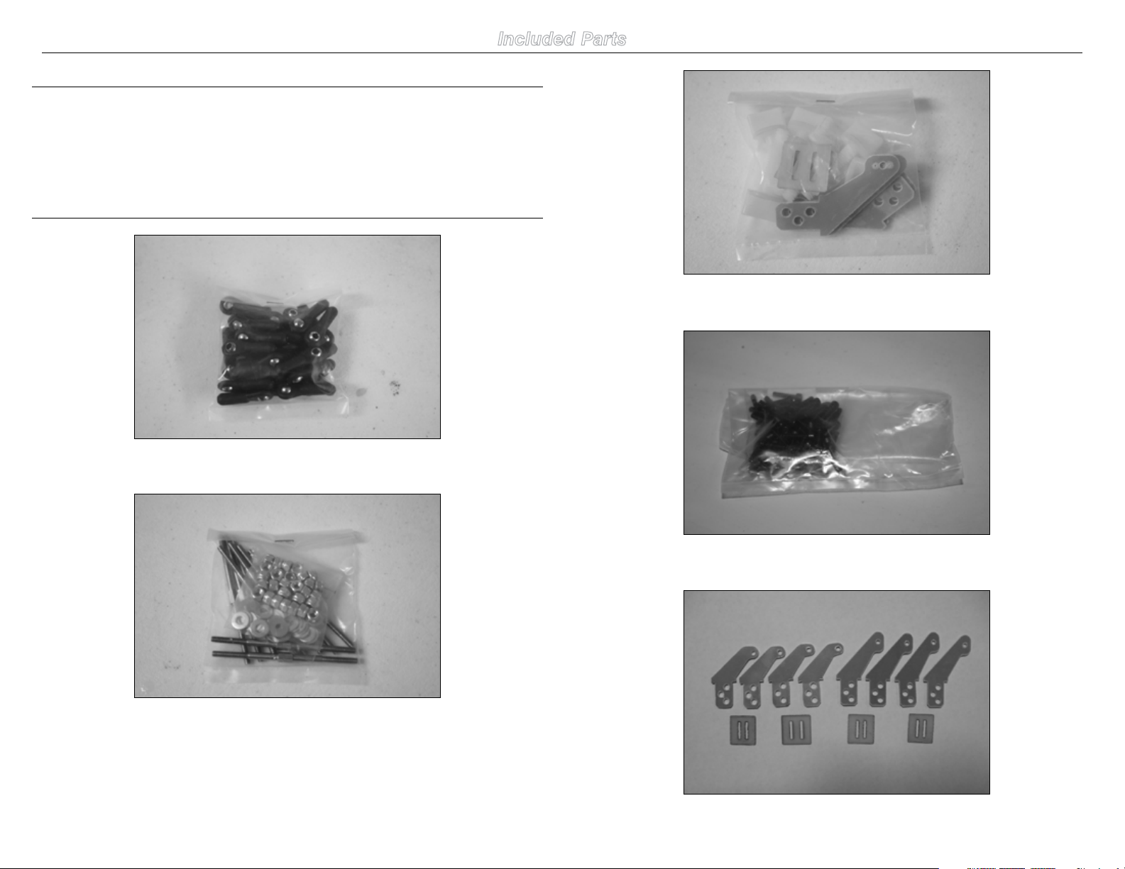
Included Parts
Aileron and Elevator Control Horns, Plates and Nylon Wing Bolts
Ball Links
Pushrods, Washers and Locknuts
2.5mm and 4-40 Screws
Left Horns (Shorter) are for Elevators and Longer Ones for Aileron
3Hangar 9 3.1m Sukhoi SU-26MM ARF Assembly Manual
Page 4
7
Safety Precautions and Warnings
4
5
15
2
11
1
8
6
17
3
Read and follow all instructions and safety precautions
before use. Improper use can result in fire, serious injury
and damage to property.
COMPONENTS
Use only with compatible components. Should any
compatibility questions exist please refer to the product
instructions, the component instructions or contact Horizon
Hobby, Inc.
FLIGHT
Fly only in open areas to ensure safety. It is recommended
flying be done at AMA (Academy of Model Aeronautics)
approved flying sites.
PROPELLER
Keep loose items that can get entangled in the propeller
away from the prop, including loose clothing, neck strap or
other objects such as pencils and screwdrivers. Especially
keep your hands away from the propeller as sever injury can
occur. Using a thick glove is highly recommended.
BATTERIES
Notes on Lithium Polymer Batteries
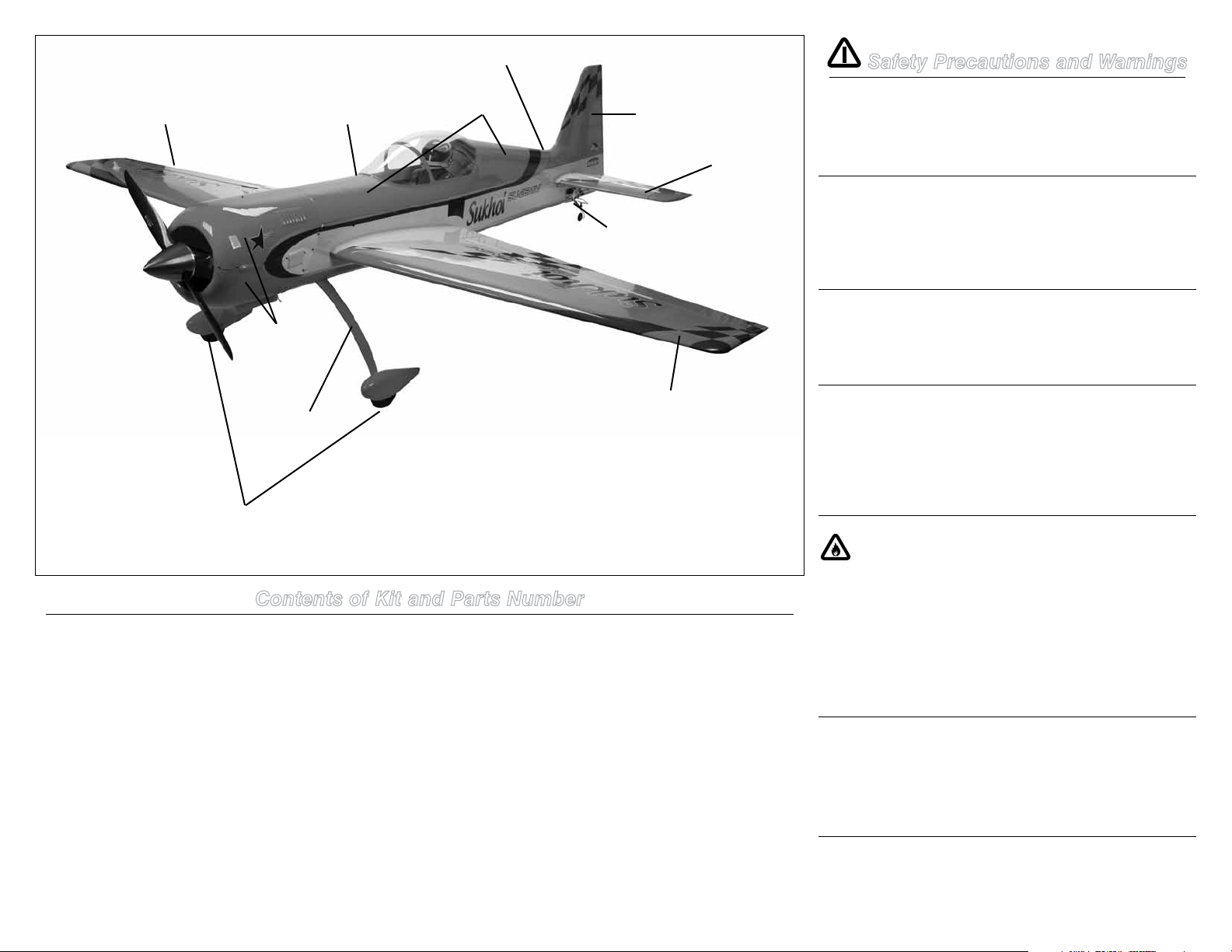
Contents of Kit and Parts Number
Replacement Parts
1. HAN106001 Fuselage w/ Hatch, 3.1m Sukhoi MM ARF
2. HAN106002 Hatch w/ Canopy, 3.1m Sukhoi MM ARF
3. HAN106003 Left Wing Panel, 3.1m Sukhoi MM ARF
4. HAN106004 Right Wing Panel, 3.1m Sukhoi MM ARF
5. HAN106005 Cowl (2 piece), 3.1m Sukhou MM ARF
6. HAN106006 Left Stab Panel, 3,1m Sukhoi MM ARF
7. HAN106007 Right Stab Panel, 3.1m SukhoiMM ARF
8. HAN106008 Rudder, 3.1m Sukhoi MM ARF
9. HAN106009 Carbon Wing Tube, 3.1m Sukhoi MM ARF
10. HAN106010 Carbon Stab Tube, 3.1m Sukhoi MM ARF
11. HAN106011 Landing Gear, 3.1m Sukhoi MM ARF
12. HAN106012 Linkage Hdwr Set, 3.1m Sukhoi MM ARF
4 Hangar 9 3.1m Sukhoi SU-26MM ARF Assembly Manual
Replacement Parts
13. HAN106013 Wheel Pant Set, 3.1m Sukhoi MM ARF
14. HAN106014 Painted Pilot, 3.1m Sukhoi MM ARF
15. HAN106015 Main Wheel Set, 3.1m Sukhoi MM ARF
16. HAN106016 Main Axle Set, 3.1m Sukhoi MM ARF
17. HAN106017 Tail Wheel Assy, 3.1m Sukhoi MM ARF
18. HAN106018 55oz Gas Tank, 3.1m Sukhoi MM ARF
19. HAN106019 Exhaust/Batt Mnt, 3.1m Sukhoi MM ARF
20. HAN106020 Cowl/Cnpy screws, 3.1m Sukhoi MM ARF
21. HAN106021 Decal Set
22. HAN106022 Wing Bolts (6), 3.1m SukhoiMM ARF
23. HAN106023 Fiberglass Control Horn Set
When misused Lithium Polymer batteries are significantly
more volatile than alkaline or Ni-Cd/Ni-MH batteries used
in RC applications. Always follow the manufacturer’s
instructions when using and disposing of any batteries.
Mishandling of Li-Po batteries can result in fire and rupture
causing serious injury and damage.
SMALL PARTS
This kit includes small parts and should not be left
unattended near children as choking and serious injury could
result.
Age Recommendation:
For advanced fliers ages 14 and above. This is not a toy.
Page 5
3.1m Sukhoi Operating Recommendations
• Inspectyourmodelbeforeeveryflighttomakecertainit
is airworthy.
• Beawareofanyotherradiofrequencyuserwhomay
present an interference problem.
• Alwaysbecourteousandrespectfulofotherusersof
your selected flight area.
• Chooseanareaclearofobstaclesandlargeenoughto
safely accommodate your flying activity.
• Makecertainthisareaisclearoffriendsandspectators
prior to launching your aircraft.
• Beawareofotheractivitiesinthevicinityofyourflight
path that could cause potential conflict.
• Carefullyplanyourflightpathpriortolaunch.
• AbidebyanyandallestablishedAMANationalModel
Aircraft Safety Code.
Important Information
Regarding Warranty
Please read our Warranty and Liability Limitations section
before building this product. If you as the purchaser or user
are not prepared to accept the liability associated with the
use of this Product, you are advised to return this Product
immediately in new and unused condition to the place of
purchase.
UltraCote® Covering Colors
•Cream HANU878
•Orange HANU877
•PearlPurple HANU847
•Silver HANU881
Recommended Setup–2-Stroke Gas
•DA150
•DA-170
Recommended Spinner
5-inch purple Tru-Turn Ultimate Style with solid back
plate.
•DA150,TT-5052-B-M-3W120-AP
•DA-170,TT-5052-B-M-DA170-AP
Optional Tuned Pipe and Canister
Installation
If you are installing the optional tuned pipe, the following
items will be required:
•50mmdropheader,14-inchlongfortunedpipe(MTW,
RE3) and 8 to 9-inch for canister (MTW TD110)
•Clamps
•Couplers
Radio Equipment Requirements
The following items are recommended when installing the
9-Channel AR91000 (SPMAR9100) in your aircraft:
DS8911HV Digital Servo (8–12) JRPS8911HV
JR 537 Servo (1) JRPS537
12-inch Servo Extension (2) (Ailerons) JRPA098
18-inch Servo Extension (2) (Ailerons) JRPA099
24-inch Servo Extension (1) (Throttle) JRPA102
36-inch Servo Extension (2) (Ailerons) JRPA103
48-inch Servo Extension (2) (Rudder) JRPA104
48-inch Servo Extension (2) (Elevators) JRPA104
(2) Receiver Packs, 4000mAh Spektrum SPMB4000LP
Ignition Pack 2000mAh Spektrum SPMB2000LP
JR Charge Switch JRPA004
JR MatchBox (4) JRPA900
Using the Manual
This manual is divided into sections to help make assembly
easier to understand, and to provide breaks between each
major section. In addition, check boxes have been placed
next to each step to keep track of each step completed.
Steps with a single box () are performed once, while
steps with two or more boxes () indicate that the step
will require repeating, such as for a right or left wing panel,
two servos, etc. Remember to take your time and follow the
directions.
Transmitter Requirements
The 3.1m Sukhoi requires a minimum of a 4-channel radio
to operate all the functions of your aircraft. However to get
the best performance from the Sukhoi, a radio with mixing
functions is recommended. We suggest the following radio
systems available through Horizon Hobby or your local
hobby distributor.
Spektrun DX8 SPM8800
JR Systems X9503 2.4GHz JRP2930
JR Systems 11X 2.4GHz JRP1100
JR Systems 12X 2.4GHz JRP1200
The Spektrum trademark is used with permission
of Bachmann Industries, Inc.
5Hangar 9 3.1m Sukhoi SU-26MM ARF Assembly Manual
Page 6
Additional Required Tools
Additional Required Adhesives
Cut-off wheel Sanding drum
Drill Epoxy brush
Felt-tipped pen Ruler
Hex wrench: 1.5mm, 2.5mm, 3mm, 4mm, 4.5mm, 3/32-
inch, 5/32-inch Iron
Hobby knife with #11 blade Mixing cup
Mixing stick Paper towel
Pencil Hemostat
Shoo Goo or Zap-A-Dap-A-Goo
Phillips screwdriver: #1, #2 Pin vise
Vise grip Masking tape
Rotary tool Rubbing alcohol
Nut driver: 1/4-inch Heat gun
Drill bit: 1/16-inch (1.5mm), 5/64-inch (2mm),
3/32-inch (2.5mm), 3/16-inch (5mm)
Medium CA (PAAPT02)
Thin CA (PAAPT08)
CA remover/debonder (PAAPT16)
CA accelerator (PAAPT15)
Threadlock (PAAPT42)
30-Minute Epoxy, 8 oz (PAAPT39)
Before Starting Assembly
Before beginning the assembly of your model, remove
each part from its bag for inspection. Closely inspect the
fuselage, wing panels, rudder and stabilizer for damage. If
you find any damaged or missing parts, contact the place of
purchase.
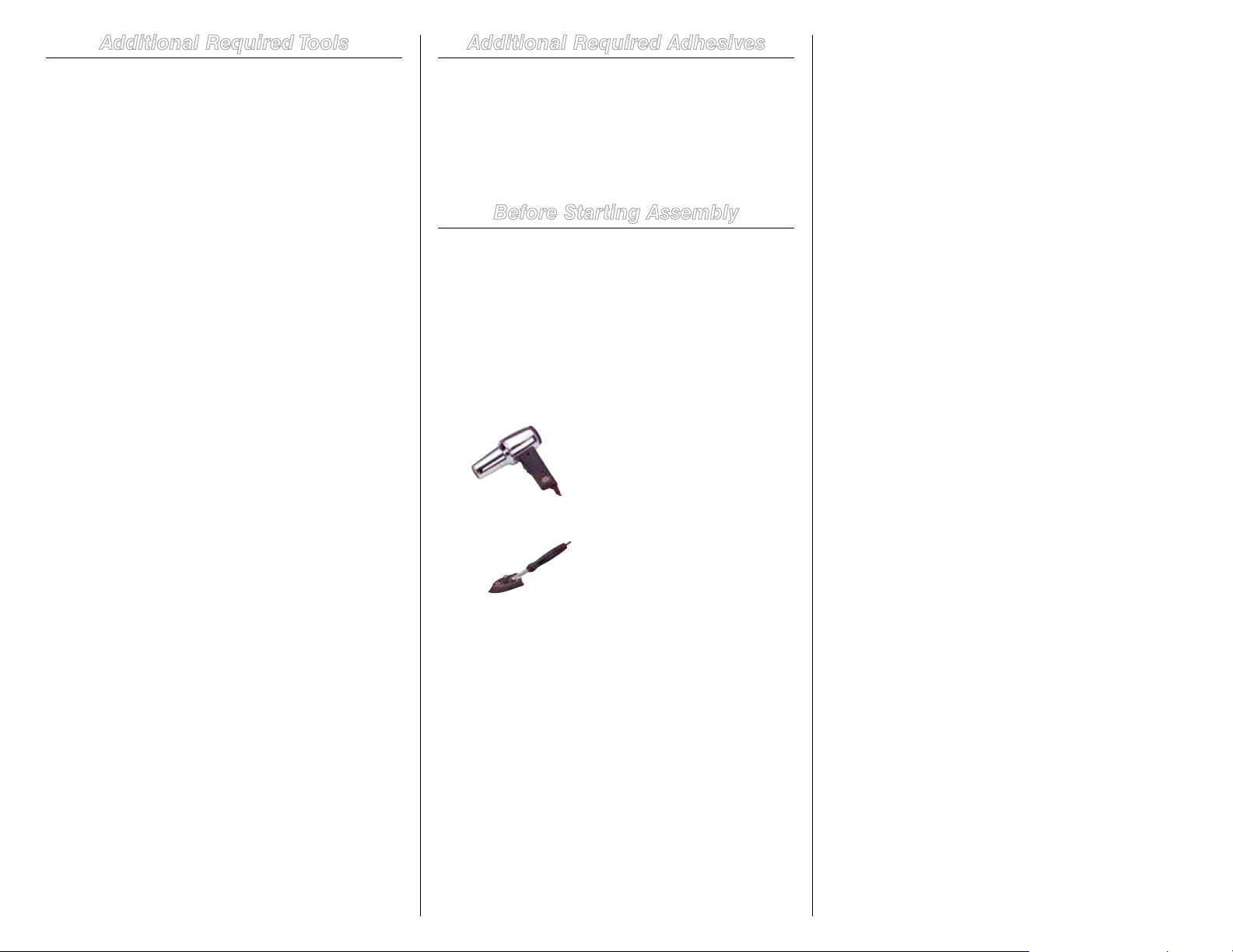
If you find any wrinkles in the covering, use a heat gun or
covering iron to remove them. Use caution while working
around areas where the colors overlap to prevent separating
the colors.
HAN100 – Heat Gun
HAN150 – Covering Glove
HAN101 – Sealing Iron
HAN141 – Sealing Iron Sock
6 Hangar 9 3.1m Sukhoi SU-26MM ARF Assembly Manual
Page 7
Aileron Servos Installation
Required Parts
Wing panel Ball link (12)
Control horns (4) (3D wing setup only)
4-40 screws (12)
7
2
/16-inch aileron pushrod (6) Locknuts (12)
Required Parts (not included)
JR 8911HV with hardware (4) or (6) or similar digital
servo
JR 1-1/2-inch servo arm (4) or (6)
JR heavy-duty servo extension, 36-inch (2)
JR heavy-duty servo extension, 18-inch (2)
Required Tools and Adhesives
Pin vise Iron
Thin CA Phillips screwdriver: #1
Drill bit: 1/16-inch 30-minute epoxy
String (Dental floss) Masking tape
Adhesive-backed hook and loop
3/32-inch ball driver Hobby knife
Wings will be setup with two different configurations,
precision and 3D. For the precision setup two servos will be
used one is mounted inboard and second servo outboard
of the wing. Middle servo bay will be left unused. This is
the configuration as the wings come out of the box. For 3D
setup, all 3 servos will be installed and middle servo control
horns need to be glued in. Follow the below steps.
be installed in.
2. Secure a 36-inch servo extension to the outboard
aileron servo lead using string or a commercially available
connector. This will prevent the extension from accidentally
disconnecting inside the wing.
4. A string has been installed in the wing to pull the
aileron servo extension through the wing. Tie or tape the
string to the end of the extension and pull the lead to the
wing root.
Precision Wing Setup
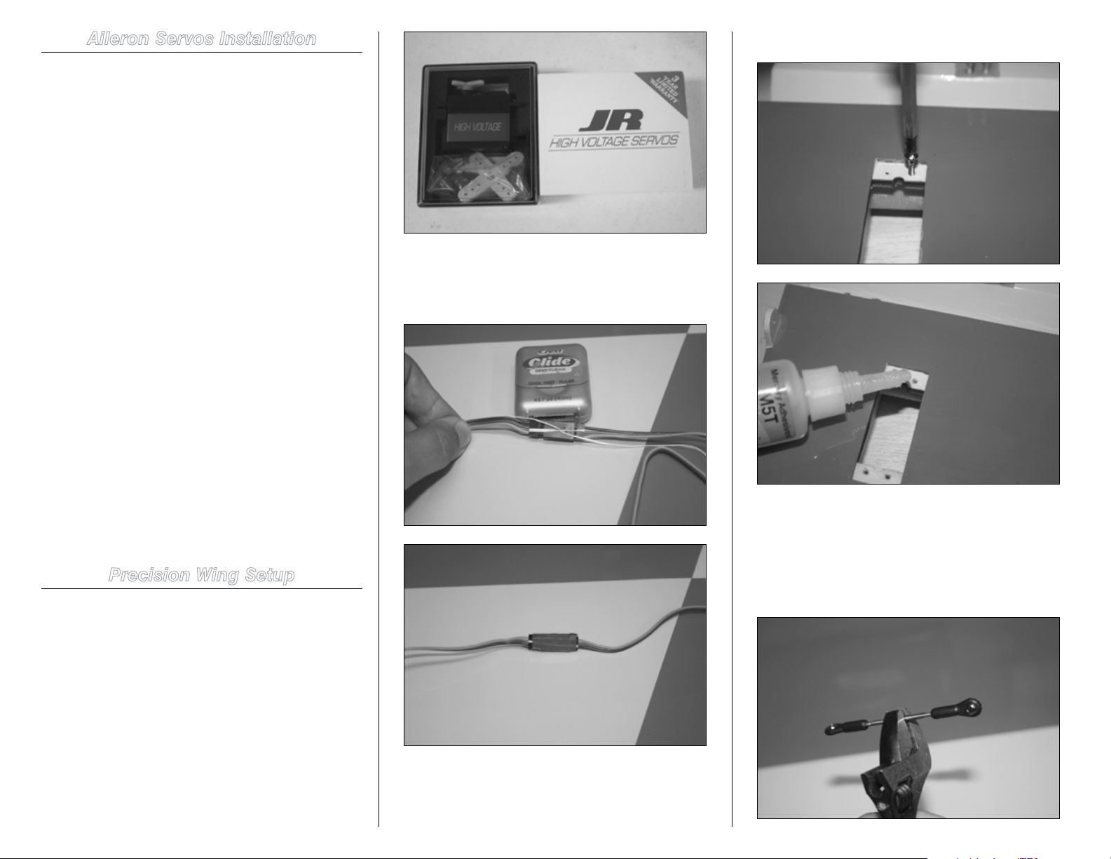
1. Prepare the aileron servos by installing the rubber
grommets and brass eyelets.
Hint: Prepare all servos for the wing at this time.
5. Mount the servo such that the output shaft faces the
leading edge and prepare the linkage for installation.
3. In order to harden the servo mounting holes in
the bays, mount the servo screws, back them out and
apply some thin CA in the hole. Wait until CA is dry before
installing the servo. Do this for every bay that a servo is to
7Hangar 9 3.1m Sukhoi SU-26MM ARF Assembly Manual
Page 8
6. Attach the linkage to the servo arm at the 1 inch
hole. If using aluminum JR arms, use the second hole from
center outward. Use threadlock on all the screws except for
the two setscrews of the arm.
7. To adjust the length of linkages, servos need to be
powered and at center. The arm should be mounted parallel
to the aileron hinge line; small adjustments can be made
using sub-trim. Adjust the length of linkage so the aileron is
centered and servo arm is parallel to the hinge line.
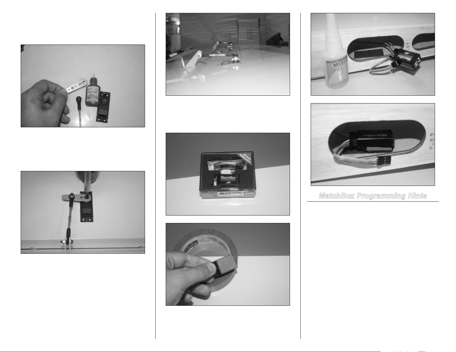
9. Mount the MatchBox™ in the wing root using sticky
back hook and loop. Before applying the hook and loop
to the MatchBox, apply masking tape to the back of the
MatchBox so it can easily be removed when need be.
MatchBox Programming Hints
The pointers below can help make matching servos easier.
This is not to take the place of the MatchBox instruction
manual.
1. Connect the inboard servo to the MatchBox and then
make all adjustments to servo center and travel adjustments
in the transmitter programming. No adjustments to this
servo should be made in the MatchBox.
8. Mount the inboard servo following the same method
as outboard but no extension is required.
8 Hangar 9 3.1m Sukhoi SU-26MM ARF Assembly Manual
2. Connect the second servo to the MatchBox to center it,
then install the servo arm onto the servo on the spline that
gets it as close to parallel with the hinge line as possible.
Then use the MatchBox to set the center of this servo so the
servo arm is exactly parallel to the hinge line. Now adjust the
linkage length so the hole in the ball link directly aligns with
the appropriate hole in the servo arm.
Now deflect the servo to full stick in one direction and use
the MatchBox to set the endpoint so the ball link directly
lines up with the hole in the servo arm. Repeat this with the
stick fully deflected in the opposite direction. Once the center
and both endpoints are set for the second servo, remember
Page 9
to turn the dial on the MatchBox back to the 0 position to
save the settings before powering off the receiver. Hint,
when adjusting for endpoints (full deflection), it is hard to
hold the sticks and adjust the MatchBox at the same time.
It is best to move the sticks to full deflection and while
holding the stick, turn off the radio. This will put the receiver
into hold and makes adjustment easier working only the
MatchBox and observing the linkage position over the servo
arm.
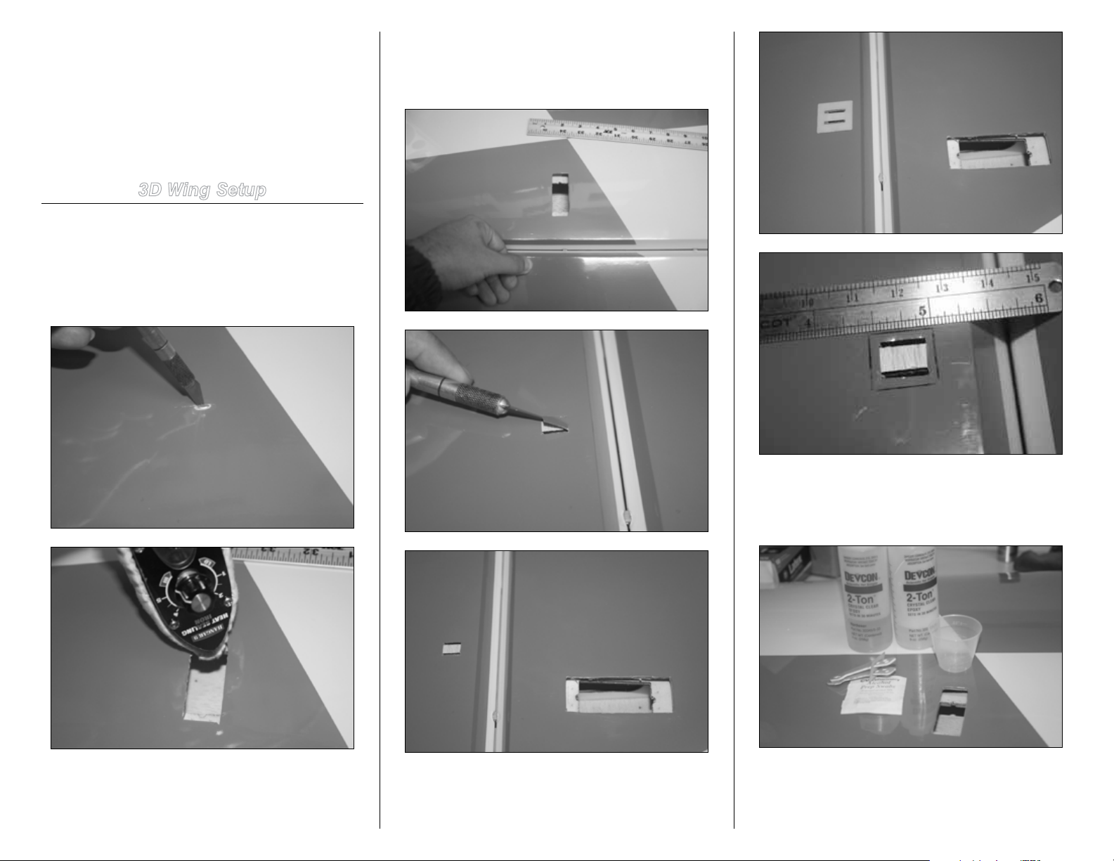
3D Wing Setup
1. 3D flying is more demanding and the addition of the
middle servo can help reduce the level of abuse servos and
wings will see. Open up the middle servo bay. Iron down the
edges. The middle servo bay is located approximately 16
inches away from the inboard servo. Rub your finger over
the covering in that vicinity to find it.
3. Find the location for control horns and remove the
covering in between the two slots. Now place the plate over
the slots and mark a slightly smaller area than the plate and
remove the covering.
2. To harden the servo mounting holes in the bay,
mount the servo screws, back them out and apply some
thin CA in the hole. Wait until CA is dry before installing the
servo. See step 3 in precision wing setup for detail.
4. Mix 30-minute epoxy and glue the horns and plate
such that the control horn pivot point is aligned with aileron
hinge line. Apply epoxy to both slots on the aileron and
control horn and plate. Clean excess with alcohol swabs.
9Hangar 9 3.1m Sukhoi SU-26MM ARF Assembly Manual
Page 10
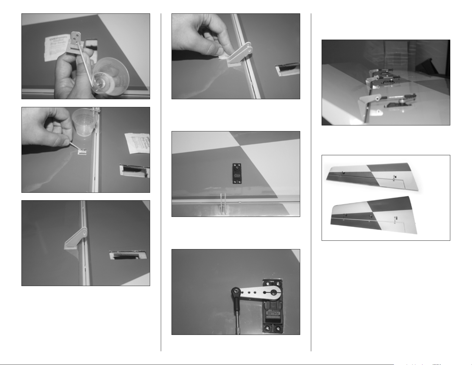
5. Attach an 18-inch JR Heavy-Duty extension to the
middle servo. Mount the servo such that the output shaft is
towards the leading edge of the wing.
7. The picture below shows the wing with a 3-servo setup
at full deflection. For MatchBox setup, refer to previous
section.
The picture below shows the comparison of precision
wing and 3D wing setup.
6. 1.5-inch servo arms are used for 3D wing setup.
Assemble the linkages and use threadlock on all the screws.
Setscrews need only tightening and no threadlock.
10 Hangar 9 3.1m Sukhoi SU-26MM ARF Assembly Manual
Page 11
Elevator Servos Installation
Required Parts
Elevator panel 4-40 screws (8)
Locknuts (8) Ball link (8)
Control horns (4) (3D elevator setup only)
7
2
/16-inch elevator pushrod (4)
Required Parts (not included)
JR 8911HV or similar digital servo (2) or (4)
JR 1.5-inch servo arm (2) or (4)
JR heavy-duty servo extension, 48-inch (2)
Required Tools and Adhesives
Pin vise Iron
Thin CA Phillips screwdriver: #1
Drill bit: 1/16-inch 30-minute epoxy
String (Dental floss) Masking tape
Adhesive-backed hook and loop
3/32-inch ball driver Hobby knife
2.5mm ball driver
Note: Elevators will be set up for both precision and 3D
flying. Due to extra demand in power and deflection of
3D flying, two servos will be used for that style.
towards the leading edge of the stab. The servo arm needs
to be 1.25 inch; if in case of using a JR aluminum servo
arm, this would be the third outermost hole.
2. Mount the servo screws and back them out.
4. Mount the servo so the output shaft is towards the
leading edge of the stab.
5. Prepare the ball link and pushrod. Attach the ball
link to the control horn using a 2.5mm ball driver and hold
the locknut with help of a vise grip or nut driver.
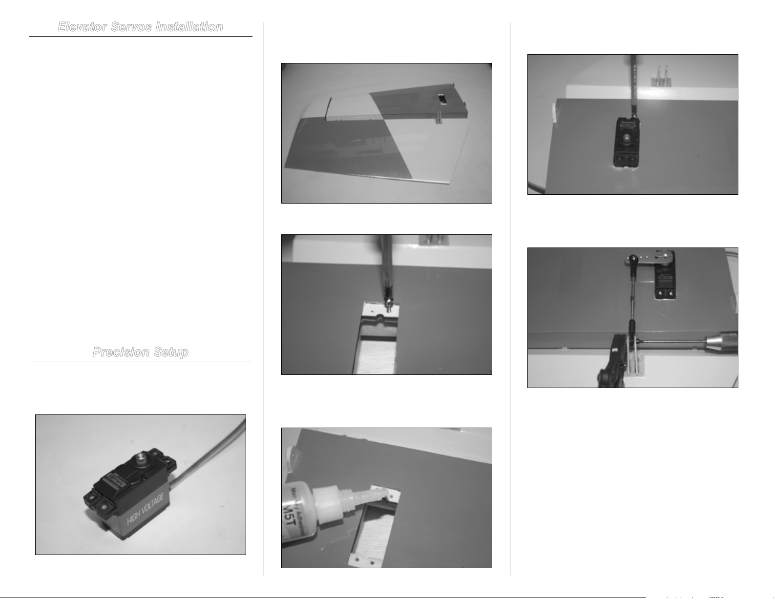
Precision Setup
1. For precision setup one servo per elevator is used.
Prepare the servo by installing the rubber grommets and
brass eyelets.
Servo needs to be installed in such way that output shaft is
3. To harden the servo mounting holes in the bay
apply some thin CA in the hole. Wait until CA is dry before
installing the servo.
6. Connect the ball link to the 1.25-inch hole on a JR
aluminum servo arm. This would be the third outermost hole
from the center of the arm. Mount the servo arm parallel to
the elevator hinge line. Use threadlock on the center servo
arm screw. Use a 48-inch JR Heavy-Duty extension from
elevator to receiver.
11Hangar 9 3.1m Sukhoi SU-26MM ARF Assembly Manual
Page 12
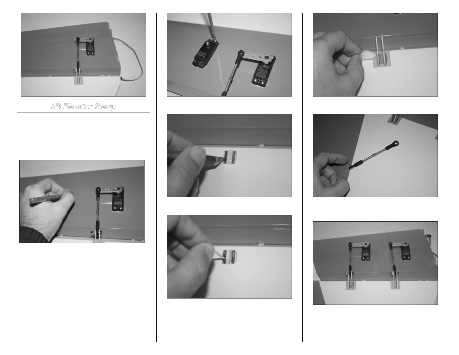
3D Elevator Setup
1. The second servo bay needs to be opened and
control horns and plate need to be glued using 15- to
30-minute epoxy. This step is also very similar to Aileron
Servo Installation in 3D section. Follow the same steps and
make sure to line up the control horn pivot point to the
elevator hinge line.
4. Remove the covering to mount the control horns.
7. Prepare the ball link and pushrod for installation.
5. Mix 30-minute epoxy and fill the control horn slots.
8. Install the ball links at the 1.5-inch hole on the arm.
Use threadlock on the center servo arm screw.
2. Mount the servo screws and back them out. Apply
some CA to harden the wood. This step is the same as steps
2 and 3 in the elevator precision setup section.
3. Mount the servo once the glue is dry.
6. Install the control horns and plate, make sure to
line up the control horns hole and elevator hinge line. Clean
excess epoxy using alcohol swabs.
12 Hangar 9 3.1m Sukhoi SU-26MM ARF Assembly Manual
9. MatchBox is installed in the stab root. Apply a piece
of masking tape to the bottom of the MatchBox and using CA
glue a piece of hook and loop to the MatchBox.
Page 13
Note: Refer to MatchBox setup in the wing section.
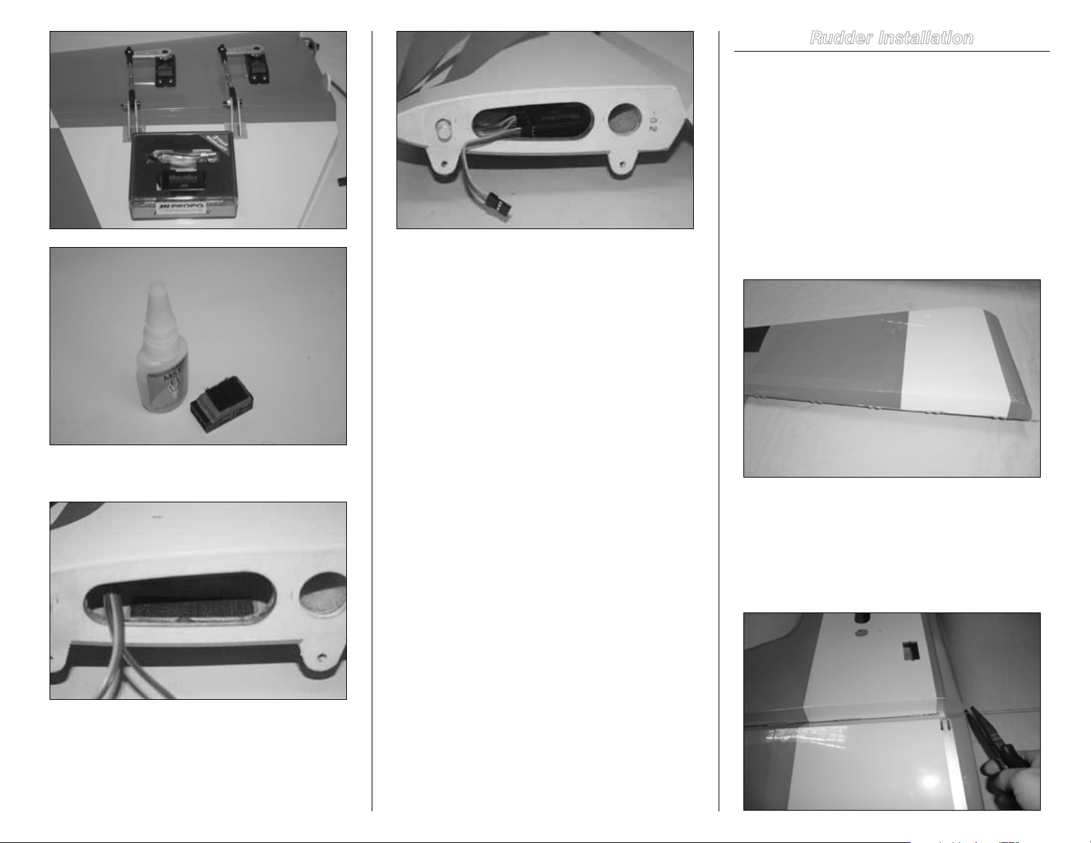
Rudder Installation
Required Parts
Fuselage Rudder
Hinge rod
Required Tools and Adhesives
Drill Pliers
Petroleum Jelly/Industrial lubricant
1. Apply some industrial lubricant to the rod. Pass the
rod through the hinges in rudder and fuselage vertical fin
separately. This helps remove any possible dirt in the hinges
and makes for easier final assembly.
10. Glue opposite side of hook and loop to stab root
with CA.
11. Mount the MatchBox. Use 48-inch extension from
MatchBox to the receiver.
2. Mate the rudder and fuselage vertical stabilizer
and carefully pass the rod through hinges. This can be
accomplished by two ways. 1. Use a drill on slow speed
and gently pass through the rod. If there is any resistance,
back out and repeat. 2. Use a pair of pliers and push the rod
through the hinges. Make sure not to buckle the rod. This is
a rather slow process and needs attention.
13Hangar 9 3.1m Sukhoi SU-26MM ARF Assembly Manual
Page 14

3. Cut excess rod long enough (1mm) that it is easy to
grab and pull out when needed for transportation. The tail
wheel bracket will stop the rod from backing out of the
hinges.
The picture below shows the rod at top end of the vertical
fin.
Rudder Servos Installation
Required Parts
Fuselage 4-40 screws (4)
Ball link (4) Locknuts (4)
3
3
/16-inch rudder pushrod (2)
Required Parts (not included)
JR 8911HV or similar digital servo (2)
JR 1.5-inch servo arm (2)
JR heavy-duty servo extension, 48-inch (2)
Required Tools and Adhesives
Pin vise Phillips screwdriver: #1
String (Dental floss) Masking tape
3/32-inch ball driver
Note: The fuselage is made to accept 4 rudder servos,
however if the recommended servos are used, only two
servos are needed even for the most extreme 3D flying.
If using servos with lower torque, remove the covering
from one or both of the additional servo bays and
connect linkages as needed.
2. Servo is mounted with output shaft facing aft. Mark the
servo mounting lugs.
1. Prepare the servo by attaching the 48-inch extension
and securing the connector with a string and masking tape
over it.
3. Use a pin vise to drill the holes.
14 Hangar 9 3.1m Sukhoi SU-26MM ARF Assembly Manual
Page 15

4. Mount the servo screws and remove.
5. Apply some thin CA to harden the wood. Once glue is
dry, mount the servo.
servo arm so it is pointing to the bottom of the fuse and is
parallel to the rudder hinge line. Use sub-trim if needed.
Note: Since there are two rudder servos used (one on
each side), they can be matched in the radio using an
Aux and P-Mix or using a MatchBox.
8. Apply threadlock on main mounting servo screw.
Tighten the setscrews without use of threadlock.
6. Prepare the servo arm by mounting the ball link and
pushrod at 1.5-inch hole out.
7. Power up the servo and with sub-trim at 0, mount the
9. Connect other side of pushrod to control horns.
10. Adjust the length of pushrod to achieve rudder center
while the arm is parallel to the hinge line.
15Hangar 9 3.1m Sukhoi SU-26MM ARF Assembly Manual
Page 16

Main Gear and Tail Gear Installation
Required Parts
Landing gear Landing gear hardware
Wheel pants Wheels
Required Tools and Adhesives
2.5mm ball driver 10mm wrench and socket
Crescent wrench 4.5mm ball driver
Threadlock Felt-tipped pen
Thin CA Pin vise
1. Locate all the hardware necessary to mount the wheels
and wheel pants.
2. Mount the axles with locknut and washer provided in the
kit using a crescent and a #10 wrench.
3. Install the wheel using the two wheel collars provided;
apply threadlock to the setscrews and slightly tighten them.
6. Tighten the setscrews and wheel pant screws using a
1.5mm and 2.5mm ball driver respectively.
4. Temporarily install the pant and center the wheel.
7. Mount the main gear using (4) 5mm bolts/washers and
5. Once the wheel is centered, remove wheel pant and
mark the axle where wheel collars sit and file a flat spot for
each collar location. Note that the collar shoulder is facing
the wheel hub.
16 Hangar 9 3.1m Sukhoi SU-26MM ARF Assembly Manual
locknuts. Use threadlock on the bolts. Hold the nut either from
inside the canister tunnel or from the top through the slots in
the fuselage floor at the sides of the tank tray. Here the locknut
is shown being held using a ratchet with a #10 socket from
inside the canister tunnel. Gear needs to be installed with
Page 17

angle slightly swept forward.
8. Tail gear is mounted using (3) 4-40 ½ inch screws and
3 washers included in the kit.
9. Mount the T-bracket and mark the holes.
11. Apply thin CA in the holes and wait until it is dry, this
will harden the wall.
12. Mount the T-bracket using small wood screws and
the tail gear using washers and screws; make sure to use
threadlock on the bolts. Hook the springs from the tiller arm
to the T-bracket and secure them.
10. Drill a pilot hole using a pin vise, then mount the
screws and remove them.
17Hangar 9 3.1m Sukhoi SU-26MM ARF Assembly Manual
Page 18

Pipes/Canisters Mount Installation and
Assembly
4. Prepare the fuselage for pipe installation. Remove the
covering as pictured and iron down the edges. Masking tape
can be used to give good guidance when cutting.
Required Parts
Pipe or canister mounts Silicone tubing
Required Parts (not included)
MTW RE3 Pipe MTW 110 Canister
50mm drop header, 14-inch for RE3 tuned pipe setup
50mm drop header, 8-9-inch for MTW 110 canister setup
Couplers Clamps
Required Tools and Adhesives
Hobby knife Felt-tipped pen
5-and 30-minute epoxy Clamps
Vise grip Iron
Rotary tool with cutter disk Ruler
Masking tape Industrial lubricant
Acid brush Mixing cup and sticks
Pipes Mount Installation
1. Kit comes with 4 pipe mounts, 2 canister mounts
and silicone tubing. Two support locations are selected for
pipe installation. Pipe mounts need to be doubled up for
increased glue surface area and strength. Scratch the surface
of each mount with a hobby knife.
Note: Final picture is shown below to give a good
perspective as where to remove the covering.
2. Glue the layers using a thin layer of 5-minute epoxy.
Clamp until glue cures.
The picture below is of the bay immediate aft of landing
gear.
3. Pass the silicone tubing through the middle hole and
go through each hole in the circumference of the mount
from the inside until you are back at the same middle hole
that you started. Cut off the silicone tubing to prepare the
next pipe mount.
18 Hangar 9 3.1m Sukhoi SU-26MM ARF Assembly Manual
Page 19

The picture below is of the tail end of the pipe tunnel.
5. Temporarily mount the pipe mounts and install pipes
to center the mounts before they are glued. Use lubricant on
the pipes for easier passage through the mounts when they
are not glued yet. Pipe mounts will not touch the floor of
the fuselage and need to be glued to the sides and bottom
former.
6. Once mounts are centered mark the spot on the sides
and formers.
7. Remove the pipes and use an acid brush to apply
30-minute epoxy to the sides of the mount and fuselage.
8. Reinstall the mounts and allow time for epoxy to cure.
19Hangar 9 3.1m Sukhoi SU-26MM ARF Assembly Manual
Page 20

Pipe Header Assembly
1. Recommended header length for MTW RE3 tuned pipe
and DA-170 is 14 inches. Assemble the pipe/header using a
vice-grip. Open the clamps and slide them over the header.
pipe and header, such that is it forward the bump on the
header and over the grooves on the pipe/canister.
3. Once everything is assembled, heat the couplers where
clamps are using a heat gun at high setting. Do this for a few
minutes and allow some time for cooling. Repeat this one
more time. This will create a good grip and reduces chance
of pipe/header slipping out in flight. It is also recommended
to do this before the first flight. Let engine idle for 3 to 4
minutes to warm up the couplers, gradually increasing the
throttle to half to get the engine hot and then allow a cooldown period before the first flight. This should not need
repeating and when done right, header/pipe will not slip out.
Canisters Mount Installation
1. Kit comes with 2 canister mounts and silicone tubing.
There is only one support location for the canister mount
that is under the landing gear area. Scratch the surface of
each mount with a hobby knife and glue the layers using a
thin layer of 5 to 15-minute epoxy. Clamp until glue is cured.
Pass the silicone tubing through the mount start with top
middle hole and end at bottom middle hole as shown in
Pipes Mount Installation section.
2. Prepare the fuselage for canister installation. Remove
the covering as pictured in first bay, under the landing gear
and iron down the edges.
2. Insert the header and pipe into coupler, leave 1/8--1/4
inch gap between header and pipe. Slide the clamps on the
20 Hangar 9 3.1m Sukhoi SU-26MM ARF Assembly Manual
Page 21

Canister/Header Assembly
1. Recommended header length for MTW TD110 canister
and DA-170 is 8--9-inches. Cut 1 inch off the stock header.
Assemble the canister/header using a vice-grip to open the
clamps and slide them over the header first then insert the
header and canister into coupler. Leave 1/8--1/4 inch gap
between header and pipe. Since the bump on the header has
to be cut for optimum performance, tap a button head 4-40
screw on the header and slide the slot of the clamp over the
button head screw and coupler to avoid slippage.
3. Temporarily mount the canister mounts and install
canisters to center the mount. Use lubricant on the canisters
for easier passage through the mounts before they are glued.
The canister mount touches the floor of the fuse and needs
to be glued to the sides and bottom former. Once mount is
centered, mark the spot on the sides and formers. Remove
the canisters and apply glue to the sides of the mount and
fuselage where they contact using 30-minute epoxy to
enough have time for adjustment.
.
21Hangar 9 3.1m Sukhoi SU-26MM ARF Assembly Manual
Page 22

Cowl Mounting
Required Parts
Cowl mounting ring Gussets
Lower cowl
Lower cowl mounting hardware
Required Tools and Adhesives
30-minute epoxy Hobby knife
Iron 3/32-inch ball driver
1. The pictures below show the cowl mounting ring
and 3 gussets. They assemble as pictured. Mount the cowl
mounting ring and open the slots where the gussets sit on
and around the engine box.
2. Dry fit everything and temporarily mount the bottom
cowl to ensure correct alignment. Adjust if necessary.
22 Hangar 9 3.1m Sukhoi SU-26MM ARF Assembly Manual
Page 23

3. Mark where the cowl mounting ring and gussets touch
the engine box and remove the covering before applying
epoxy. The picture below shows where the gusset attaches
to the cowl mounting ring and engine box.
4. Mix 30-minute epoxy and apply glue to the gussets
and cowl mount ring, also rub some epoxy in the slots
where the gusset tabs interlock, then glue the mounts in
place. Attach bottom cowl and wait until epoxy is set before
removing the cowl. This ensures the cowl mount ring and
gussets are glued and aligned properly. Clean excess epoxy
with alcohol swabs.
5. Mount the lower half cowl.
6. Mount the upper half cowl. At the mid-point that both
lower and upper half meet, use colored washers and 1/4 inch
4-40 screws.
23Hangar 9 3.1m Sukhoi SU-26MM ARF Assembly Manual
Page 24

Engine, Throttle Servo and DA Muffler
Installation
Required Parts
1/4-20 1-inch bolts (4)
Required Parts (not included)
DA-170 Engine DA stock muffler
JR-537 servo (1)
JR 24-inch servo extension
Required Tools and Adhesives
Threadlock 4.5mm hex wrench
Hobby knife with #11 blade Felt-tipped pen
Pin vise Phillips screwdriver
Rotary tool with sanding drum
1. Mount the engine using 1-inch ¼-20 bolts provided
and make sure to apply threadlock to all the bolts.
2. Mount the throttle servo so that the servo output shaft
is closer to the front of the engine. DA-170 comes with a
4-40 ball link attached to the throttle lever. Screw the 6 1/2inch 4-40 rod into DA ball link and ball link provided with the
kit. Apply threadlock to the servo arm screw. Throttle servo
needs 24-inch extension.
24 Hangar 9 3.1m Sukhoi SU-26MM ARF Assembly Manual
3. Install the mufflers so DA logo on the muffler is
pointed towards the front and smoke nipples are facing
outboard of the plane on both sides. Use gasket provided or
high-temperature RTV and apply threadlock to the muffler
bolts.
Page 25

4. Use cutting disk, drum sander and a rotary tool to
cut the cowl. Holes need to be at least 1/4 inch larger than
muffler stack diameter.
Fuel Tank, Fill and Over Flow
Installation
Required Parts
Fuselage Fuel tank
Required Parts (not included)
Hangar 9 Fuel filler and T
Required Tools and Adhesives
Drill and bits (1/16-inch, 1/8-inch)
Zip tie Hemostat
Double-sided tape or adhesive-backed hook and loop
Medium CA Hook and loop staps
Rotary tool Sanding Drum (3/8-inch)
1. Fuel tank comes assembled but not installed. It is
recommended that lines be checked every 2–3 months and
replace them if they have hardened.
2. Fill line is installed at the front left side of the
fuselage using Hangar 9 fuel filler. Drill a small hole; then
using a rotary tool and 3/8-inch diameter sanding drum
or grinding bit, open the side of the fuselage for the fuel
filler.
3. Tank fill line goes to a T. Use the straight path outlet
to connect to carb and other to fuel filler. Wrap safety wires
around the lines.
25Hangar 9 3.1m Sukhoi SU-26MM ARF Assembly Manual
Page 26

6. Glue two pieces of hook and loop to the tank tray using
medium CA.
4. To secure the fuel tank from forward/aft motion,
double-sided or servo tape should be applied to the bottom
of the tank. There is no foaming issue with hard-mounted
tanks in gas engines.
For removable setup, apply a couple of pieces of masking
tape to the bottom of the tank.
5. Glue a piece of hook and loop to the masking tape using
medium CA.
9. Mount the lower cowl and mark behind the bottom left
louver. Use rotary tool to open the lower cowl, big enough to
pass the overflow line.
7. Strap the tank with hook and loop strips provided.
Loop the overflow line around the tank.
8. Overflow line goes through the fuselage floor opening
to the lower bottom cowl.
10. Cut 1/4-inch fuel line.
26 Hangar 9 3.1m Sukhoi SU-26MM ARF Assembly Manual
Page 27

Ignition Module, Battery, Regulator
and Switch Installation
Required Parts
Fuselage
Required Parts (not included)
JR 5203 regulator Ignition Module
Ignition Battery, 2000 2-cell Spektrum
JR heavy-duty switch or similar
JR heavy-duty 6-inch extension
11. To help prevent the line from going back inside the
cowl, open up the fuel line with use of hemostat and pull
over the overflow line.
Required Tools and Adhesives
Hobby knife Iron
Masking tape Medium CA
Hook and loop Double-sided tape
1. Locate the ignition switch cut out in the right front of
the fuselage and remove the covering. Mount the ignition
switch.
2. Locate the slots for the ignition module behind the
cowl mounting ring and remove the covering.
3. Iron down the edges and the covering on the engine
box.
4. The ignition module and battery will be installed as one
piece, on top of each other. Apply masking tape to both sides
of battery and bottom side of ignition module.
27Hangar 9 3.1m Sukhoi SU-26MM ARF Assembly Manual
Page 28

5. Apply servo/double-sided tape between battery and
ignition module.
7. Apply opposite side of adhesive-backed hook and loop
to the engine box.
9. Ignition will be mounted next to ignition module
and battery. Glue a piece of hook and loop next to ignition
module and battery.
6. Glue ¼-inch thick DuBro foam to the bottom of the
battery using CA. Glue a piece of hook and loop to the foam.
8. Mount the ignition and battery as one piece and strap
it with hook and loop straps. Provide an overlap of 2 inches
for the strap to wrap around the battery and ignition module
through the slots.
10. Apply a piece of masking tape to the bottom of
regulator and glue opposite side of hook and loop using CA.
28 Hangar 9 3.1m Sukhoi SU-26MM ARF Assembly Manual
Page 29

11. Mount the regulator.
Receiver Mount and Throttle Servo
Regulator Installation
Required Parts
Receiver tray and stands Fuselage
Required Parts (not included)
JR 5203 regulator Receiver
Required Tools and Adhesives
Masking tape CA thin and medium
CA accelerator 5-minute epoxy
Dubro 1/4-inch foam Hook and loop
Hook and loop
1. Prepare the receiver to mount on the tray, similar to
the ignition battery preparation in the previous section. Put
two rounds of masking tape at the bottom of the receiver.
Using CA glue 1/4-inch DuBro foam to the masking tape and
glue a piece of hook and loop to the foam.
3. Throttle servo regulator is mounted next to the receiver
using two pieces of hook and loop similar to step 1.
12. Use the excess strap from the ignition module and
pull it over the ignition.
Note: Connect battery to switch, output of the switch
to regulator (6-inch extension is needed) and regulator
output to ignition. With this method, battery can be
charged directly through the switch charge port.
4. Glue balsa sticks using thin CA to the floor of the
fuselage.
2. Glue opposite side of the hook and loop to the tray and
mount the receiver.
29Hangar 9 3.1m Sukhoi SU-26MM ARF Assembly Manual
Page 30

5. Glue the tray on the balsa stick using either Medium
CA or 5-minute epoxy. Hold pressure on the tray until glue
dries or epoxy sets.
Receiver Battery Installation
Required Parts
Fuselage
Required Parts (not included)
(2) Spektrum 4000 2-cell LiPo
(2) 12-inch EC3™ extensions
Required Tools and Adhesives
Medium CA Masking tape
Hook and loop Hook and loop straps
1. Apply masking tape to the bottom of the batteries.
Glue hook and loop using CA to the masking tape. Applying
CA in addition to the adhesive already on the hook and loop
ensures glue does not come undone on hot days.
the kit and secure the batteries by passing the strips through
the top and bottom slots.
The picture below shows the right battery setup.
6. Strap the receiver using hook and loop.
The picture below shows the left battery setup.
2. Glue using CA opposite side of hook and loop to the
sides of the fuselage as shown below.
3. Overlap 2 inches of hook and loop straps provided in
30 Hangar 9 3.1m Sukhoi SU-26MM ARF Assembly Manual
Page 31

Satellite Receiver and Receiver Switch
Installation
Required Parts
Fuselage
Required Parts (not included)
(3 to 4) Satellite receivers
Receiver switch
Required Tools and Adhesives
Double-sided tape Masking tape
Hook and loop Threadlock
Medium CA
Note: It is best to use 4 satellite receivers as this is
a large model, however, with proper placement of
the satellite receivers, 3 would be adequate. A Flight
Log can help with correct placement of the satellite
receivers. Check the health of the system before first
flight.
1. Remove the covering from the right side of the
fuselage and mount the receiver switch. Apply a small
amount of threadlock to the screws.
2. There are two ways to mount the satellite receivers.
One way is to simply apply a piece of double-sided/servo
tape to the back of the satellite receiver and attach to the
fuselage. See step 3 for the alternative method.
4. Using the same method glue the opposite side of
the hook and loop to those parts of the fuselage where
the satellite receivers will attach. Note the recommended
locations in the following pictures.
3. Attach a piece of masking tape to the back of the
satellite receiver; apply a couple of drops of CA to the
masking tape and stick a piece of hook and loop to the
masking tape. Note that even if the hook and loop is
adhesive-backed, CA helps hold the hook and loop to the
masking tape in high temperatures.
31Hangar 9 3.1m Sukhoi SU-26MM ARF Assembly Manual
Page 32

Pilot/Panel Assembly and Installation
Required Parts
Pilot Pilot hardware
Required Tools and Adhesives
3/32-inch ball driver Threadlock
Music wire, .050-inch (not included)
Flexible adhesive (Shoo Goo or Zap-A-Dap-A-Goo)
Foam-Safe CA
1. Pilot head comes in two pieces with two screws and
washers. Apply threadlock to bolts and pass them through
the lower body of the pilot through the head.
2. Glue the pilot using Shoo Goo to the place allocated in
the canopy.
3. Locate the foam pilot panel and pilot panel decal.
32 Hangar 9 3.1m Sukhoi SU-26MM ARF Assembly Manual
Page 33

3. Peel the decal and stick to the foam pilot panel.
Center of Gravity
An important part of preparing the aircraft for flight is
properly balancing the model.
Caution: Do not inadvertently skip this step!
The recommended Center of Gravity (CG) location for your
model is 10.5 inches forward from the trailing edge of the
wing tip as shown. Mark the location of the CG on the top
of the wing with a felt-tipped pen.
Use help to lift the plane from the marked position.
For 3D flying 10 inches forward of trailing edge is
recommended; however, the 10.5 inches is the best overal
CG for both precision and 3D flying.
4. Glue the foam panel using foam-safe CA to the canopy.
5. Canopy bolts to the fuselage using 4 (4mm) screws
provided.
After the first flights, the CG position can be adjusted for
your personal preference.
33Hangar 9 3.1m Sukhoi SU-26MM ARF Assembly Manual
Page 34

Applying Decals
Kit comes with decal sets and all decals are die-cut. All large decals should be applied wet so the bubbles can be worked out by squeegee. Allow 24 hours for decals to dry and adhesive to
set.
It is important to take all the wrinkles in the covering out and would be best to apply the decals after the plane has been taken to a flying field a couple of times and all the wrinkles have
been removed. The following pictures show the location of decals.
Wing Decal Close-up
34 Hangar 9 3.1m Sukhoi SU-26MM ARF Assembly Manual
Page 35

Applying Decals
Fuselage Decal Close-up
35Hangar 9 3.1m Sukhoi SU-26MM ARF Assembly Manual
Page 36

Control Throws
Aileron:
Pro-Tips
1. Turn on the transmitter and receiver of your model.
Check the movement of the rudder using the transmitter.
When the stick is moved right, the rudder should also move
right. Reverse the direction of the servo at the transmitter if
necessary.
2. Check the movement of the elevator with the radio
system. Moving the elevator stick toward the bottom of the
transmitter will make the airplane elevator move up.
3. Check the movement of the ailerons with the radio
system. Moving the aileron stick right will make the right
aileron move up and the left aileron move down.
4. Use a throw meter to adjust the throw of the elevator,
ailerons and rudder.
Mike McConville has three flight modes as follows:
1. Normal: This flight mode is used for most precision
maneuvers.
2. Roller: This flight mode is used for spins, hammer head
and rolling circles. It has more rudder and elevator compared
to Normal flight mode.
3. High (3D): All surfaces at full deflection for 3D flying.
Mike’s plane uses 1% down elevator mix to throttle for down
lines and 5% up elevator to eliminate the pitch coupling in
knife edge. Please note this is very C.G dependant.
See Pro-Tips section for more details.
High Rate: Expo
Up: 34 degrees 45%
Down: 33 degrees 45%
Roller Rate: Expo
Up: 25.5 degrees 46%
Down: 25 degrees 46%
Normal Rate: Expo
Up: 28.5 degrees 45%
Down: 28 degrees 45%
Rudder:
High and Roller Rate: Expo
Right: 40 degrees 56%
Left: 40 degrees 56%
Normal Rate:
Right: 23 degrees 45%
Left: 23 degrees 45%
These are general guidelines measured from our own flight
tests. You can experiment with higher rates to match your
preferred style of flying.
Note: Travel Adjust, Sub-Trim and Dual Rates are
not listed and should be adjusted according to each
individual model and preference.
Important mixes that should be done correctly for precision
flying are as follows; this is besides the pitch coupling
mixes.
1. Downline Mix: Mike McConville’s plane needs only 1%
of down elevator that comes on at low end of idle. It is
important that this is done correctly to avoid inadvertent
down elevator when it is not needed.
2. For roller flight mode, Mike uses an elevator to elevator
mix that allows the elevator feel around center stick to be
the same as normal flight mode and increases elevator
throw at the extreme stick movement for spins and other
maneuvers that need extra elevator deflection. This is without
compromising the precision feel of the elevator.
Elevator:
High Rate: Expo
Up: 43 degrees 70%
Down: 43 degrees 70%
Roller: Expo
Up: 14.5 degrees 42% See Pro-Tips
Down: 14.5 degrees 42%
Normal: Expo
Up: 10.5 degrees 42%
Down: 10.5 degrees 42%
36 Hangar 9 3.1m Sukhoi SU-26MM ARF Assembly Manual
Page 37

Preight
Safety Do’s and Don’ts for Pilots
Check Your Radio
Before going to the field, be sure your batteries are
fully charged per your radio’s instructions. Charge the
transmitter and motor battery for your airplane. Use the
recommended charger supplied with your particular radio
system, following the instructions provided with the radio.
In most cases, the radio should be charged the night before
going out flying.
Before each flying session, be sure to range check your
radio. See your radio manual for the recommended
range and instructions for your radio system. Each radio
manufacturer specifies different procedures for their radio
systems. Next, run the motor. With the model securely
anchored, check the range again. The range test should not
be significantly affected. If it is, don’t attempt to fly! Have
your radio equipment checked out by the manufacturer.
Double-check that all controls (aileron, elevator, rudder and
throttle) move in the correct direction.
Check the radio installation and make sure all the control
surfaces are moving correctly (i.e., the correct direction and
with the recommended throws).
Check all the control horns, servo horns, and clevises to
make sure they are secure and in good condition.
Range Test Your Radio
Before each flying session, and especially with a new model,
it is important to perform a range check. It is helpful to have
another person available to assist during the range check. If
you are using a Spektrum transmitter, please refer to your
transmitter’s manual for detailed instructions on the range
check process.
• Consultlocallawsandordinancesbeforechoosinga
location to fly your aircraft.
• Checkallcontrolsurfacespriortoeachtakeoff.
• Donotflyyourmodelnearspectators,parkingareasor
any other area that could result in injury to people or
damage of property.
• Donotflyduringadverseweatherconditions.Poor
visibility can cause disorientation and loss of control of
your aircraft. Strong winds can cause similar problems.
• Donottakechances.Ifatanytimeduringflight
you observe any erratic or abnormal operation, land
immediately and do not resume flight until the cause of
the problem has been ascertained and corrected. Safety
can never be taken lightly.
• Donotflynearpowerlines.
Daily Flight Checks
• 1.Checkthebatteryvoltageofthetransmitterbattery.
Do not fly below the manufacturer’s recommended
voltage. To do so can crash your aircraft.
When you check these batteries, ensure you have the
polarities correct on your expanded scale voltmeter.
• 2.Checkallhardware(linkages,screws,nuts,andbolts)
prior to each day’s flight. Be sure that binding does not
occur and that all parts are properly secured.
• 3.Ensureallsurfacesaremovinginthe
proper manner.
• 4.Performagroundrangecheckbeforeeachday’s
flying session.
• 5.Priortostartingyouraircraft,turnoffyour
transmitter, then turn it back on. Do this each time you
start your aircraft. If any critical switches are on without
your knowledge, the transmitter alarm will sound a
warning at this time.
• 6.Checkthatalltrimleversareintheproperlocation.
• 7.Allservopigtailsandswitchharnessplugsshouldbe
secured in the receiver. Make sure the switch harness
moves freely in both directions.
37Hangar 9 3.1m Sukhoi SU-26MM ARF Assembly Manual
Page 38

Warranty and Repair Policy
WARRANTY PERIOD
Exclusive Warranty- Horizon Hobby, Inc., (Horizon)
warranties that the Products purchased (the “Product”) will
be free from defects in materials and workmanship at the
date of purchase by the Purchaser.
LIMITED WARRANTY
Horizon reserves the right to change or modify this
warranty without notice and disclaims all other
warranties, express or implied.
(a) This warranty is limited to the original Purchaser
(“Purchaser”) and is not transferable. REPAIR OR REPLACEMENT
AS PROVIDED UNDER THIS WARRANTY IS THE EXCLUSIVE
REMEDY OF THE PURCHASER. This warranty covers only those
Products purchased from an authorized Horizon dealer. Third
party transactions are not covered by this warranty. Proof of
purchase is required for all warranty claims.
(b) Limitations- HORIZON MAKES NO WARRANTY OR
REPRESENTATION, EXPRESS OR IMPLIED, ABOUT NONINFRINGEMENT, MERCHANTABILITY OR FITNESS FOR A
PARTICULAR PURPOSE OF THE PRODUCT. THE PURCHASER
ACKNOWLEDGES THAT THEY ALONE HAVE DETERMINED THAT
THE PRODUCT WILL SUITABLY MEET THE REQUIREMENTS OF
THE PURCHASER’S INTENDED USE.
(c) Purchaser Remedy- Horizon’s sole obligation hereunder shall
be that Horizon will, at its option, (i) repair or (ii) replace, any
Product determined by Horizon to be defective. In the event of
a defect, these are the Purchaser’s exclusive remedies. Horizon
reserves the right to inspect any and all equipment involved in a
warranty claim. Repair or replacement decisions are at the sole
discretion of Horizon. This warranty does not cover cosmetic
damage or damage due to acts of God, accident, misuse, abuse,
negligence, commercial use, or modification of or to any part
of the Product. This warranty does not cover damage due to
improper installation, operation, maintenance, or attempted
repair by anyone other than Horizon. Return of any Product
by Purchaser must be approved in writing by Horizon before
shipment.
DAMAGE LIMITS
HORIZON SHALL NOT BE LIABLE FOR SPECIAL, INDIRECT
OR CONSEQUENTIAL DAMAGES, LOSS OF PROFITS OR
PRODUCTION OR COMMERCIAL LOSS IN ANY WAY
CONNECTED WITH THE PRODUCT, WHETHER SUCH CLAIM
IS BASED IN CONTRACT, WARRANTY, NEGLIGENCE, OR
STRICT LIABILITY. Further, in no event shall the liability of
Horizon exceed the individual price of the Product on which
liability is asserted. As Horizon has no control over use,
setup, final assembly, modification or misuse, no liability
shall be assumed nor accepted for any resulting damage or
injury. By the act of use, setup or assembly, the user accepts
all resulting liability.
If you as the Purchaser or user are not prepared to accept
the liability associated with the use of this Product, you
are advised to return this Product immediately in new and
unused condition to the place of purchase.
Law: These Terms are governed by Illinois law (without
regard to conflict of law principals).
Warranty Services
QUESTIONS, ASSISTANCE, AND REPAIRS
Your local hobby store and/or place of purchase cannot
provide warranty support or repair. Once assembly, setup
or use of the Product has been started, you must contact
Horizon directly. This will enable Horizon to better answer
your questions and service you in the event that you may
need any assistance. For questions or assistance, please
direct your email to productsupport@horizonhobby.com, or
call 877.504.0233 toll free to speak to a Product Support
representative. You may also find information on our website
at www.horizonhobby.com.
INSPECTION OR REPAIRS
If this Product needs to be inspected or repaired, please
use the Horizon Online Repair Request submission process
found on our website or call Horizon to obtain a Return
Merchandise Authorization (RMA) number. Pack the Product
securely using a shipping carton. Please note that original
boxes may be included, but are not designed to withstand
the rigors of shipping without additional protection. Ship
via a carrier that provides tracking and insurance for lost
or damaged parcels, as Horizon is not responsible for
merchandise until it arrives and is accepted at our facility.
An Online Repair Request is available at http://www.
horizonhobby.com under the Repairs tab. If you do not have
internet access, please contact Horizon Product Support to
obtain a RMA number along with instructions for submitting
your product for repair. When calling Horizon, you will be
asked to provide your complete name, street address, email
address and phone number where you can be reached during
business hours. When sending product into Horizon, please
include your RMA number, a list of the included items, and a
brief summary of the problem. A copy of your original sales
receipt must be included for warranty consideration. Be sure
your name, address, and RMA number are clearly written on
the outside of the shipping carton.
Notice: Do not ship batteries to Horizon. If you have
any issue with a battery, please contact the appropriate
Horizon Product Support office.
38 Hangar 9 3.1m Sukhoi SU-26MM ARF Assembly Manual
Page 39

WARRANTY INSPECTION AND REPAIRS
To receive warranty service, you must include your original
sales receipt verifying the proof-of-purchase date. Provided
warranty conditions have been met, your Product will be
repaired or replaced free of charge. Repair or replacement
decisions are at the sole discretion of Horizon.
NON-WARRANTY REPAIRS
Should your repair not be covered by warranty the repair
will be completed and payment will be required without
notification or estimate of the expense unless the expense
exceeds 50% of the retail purchase cost. By submitting the
item for repair you are agreeing to payment of the repair
without notification. Repair estimates are available upon
request. You must include this request with your repair.
Non-warranty repair estimates will be billed a minimum of ½
hour of labor. In addition you will be billed for return freight.
Horizon accepts money orders and cashiers checks, as well
as Visa, MasterCard, American Express, and Discover cards.
By submitting any item to Horizon for inspection or repair,
you are agreeing to Horizon’s Terms and Conditions found
on our website under the Repairs tab.
Please note: non-warranty repair is only available on
electronics and model engines.
United States:
Electronics and engines requiring inspection or repair
should be shipped to the following address:
Horizon Service Center
4105 Fieldstone Road
Champaign, Illinois 61822
USA
All other Products requiring warranty inspection or repair
should be shipped to the following address:
Horizon Product Support
4105 Fieldstone Road
Champaign, Illinois 61822
USA
United Kingdom:
Electronics and engines requiring inspection or repair
should be shipped to the following address:
Horizon Hobby Limited
Units 1-4 Ployters Rd
Staple Tye
Harlow, Essex
CM18 7NS
United Kingdom
Please call +44 (0) 1279 641 097 or e-mail us at sales@
horizonhobby.co.uk with any questions or concerns
regarding this product or warranty.
Germany:
Electronics and engines requiring inspection or repair
should be shipped to the following address:
Horizon Technischer Service
Hamburger Strasse 10
25335 Elmshorn
Germany
Please call +49 4121 46199 66 or e-mail us at service@
horizonhobby.de with any questions or concerns regarding
this product or warranty.
France:
Horizon Hobby SAS
14 Rue Gustave Eiffel
Zone d’Activité du
Réveil Matin
91230 Montgeron
Please call +33 (0) 1 60 47 44 70 with any questions or
concerns regarding this product or warranty.
Compliance Information for the
European Union
INSTRUCTIONS FOR DISPOSAL OF WEEE BY
USERS IN THE EUROPEAN UNION
This product must not be disposed of with other waste.
Instead, it is the user’s responsibility to dispose of their
waste equipment by handing it over to a designated
collection point for the recycling of waste electrical and
electronic equipment. The separate collection and recycling
of your waste equipment at the time of disposal will help to
conserve natural resources and ensure that it is recycled in
a manner that protects human health and the environment.
For more information about where you can drop off your
waste equipment for recycling, please contact your local city
office, your household waste disposal service or where you
purchased the product.
Please call 877-504-0233 or e-mail us at productsupport@
horizonhobby.com with any questions or concerns regarding
this product or warranty.
39Hangar 9 3.1m Sukhoi SU-26MM ARF Assembly Manual
Page 40

2010 Official Academy of Model
Aeronautics Safety Code
GENERAL
1. A model aircraft shall be defined as a non-humancarrying device capable of sustained flight in the
atmosphere. It shall not exceed limitations established
in this code and is intended to be used exclusively for
recreational or competition activity.
2. The maximum takeoff weight of a model aircraft,
including fuel, is 55 pounds, except for those flown
under the AMA Experimental Aircraft Rules.
3. I will abide by this Safety Code and all rules established
for the flying site I use. I will not willfully fly my model
aircraft in a reckless and/or dangerous manner.
4. I will not fly my model aircraft in sanctioned events,
air shows, or model demonstrations until it has been
proven airworthy.
5. I will not fly my model aircraft higher than approximately
400 feet above ground level, when within three (3) miles
of an airport without notifying the airport operator. I will
yield the right-of-way and avoid flying in the proximity of
full-scale aircraft, utilizing a spotter when appropriate.
6. I will not fly my model aircraft unless it is identified with
my name and address, or AMA number, inside or affixed
to the outside of the model aircraft. This does not apply
to model aircraft flown indoors.
7. I will not operate model aircraft with metal-blade
propellers or with gaseous boosts (other than air),
nor will I operate model aircraft with fuels containing
tetranitromethane or hydrazine.
8. I will not operate model aircraft carrying pyrotechnic
devices which explode burn, or propel a projectile of
any kind. Exceptions include Free Flight fuses or devices
that burn producing smoke and are securely attached
to the model aircraft during flight. Rocket motors up
to a G-series size may be used, provided they remain
firmly attached to the model aircraft during flight. Model
rockets may be flown in accordance with the National
Model Rocketry Safety Code; however, they may not be
launched from model aircraft. Officially designated AMA
Air Show Teams (AST) are authorized to use devices
and practices as defined within the Air Show Advisory
Committee Document.
9. I will not operate my model aircraft while under the
influence of alcohol or within eight (8) hours of having
consumed alcohol.
10. I will not operate my model aircraft while using any drug
which could adversely affect my ability to safely control
my model aircraft.
11. Children under six (6) years old are only allowed on a
flightline or in a flight area as a pilot or while under flight
instruction.
12. When and where required by rule, helmets must be
properly worn and fastened. They must be OSHA, DOT,
ANSI, SNELL or NOCSAE approved or comply with
comparable standards.
RADIO CONTROL
1. All model flying shall be conducted in a manner to avoid
over flight of unprotected people.
2. I will have completed a successful radio equipment
ground-range check before the first flight of a new or
repaired model aircraft.
3. I will not fly my model aircraft in the presence of
spectators until I become a proficient flier, unless I am
assisted by an experienced pilot.
4. At all flying sites a line must be established, in front of
which all flying takes place. Only personnel associated
with flying the model aircraft are allowed at or in front of
the line. In the case of airshows demonstrations straight
line must be established. An area away from the line
must be maintained for spectators. Intentional flying
behind the line is prohibited.
5. I will operate my model aircraft using only radiocontrol frequencies currently allowed by the Federal
Communications Commission (FCC). Only individuals
properly licensed by the FCC are authorized to operate
equipment on Amateur Band frequencies.
6. I will not knowingly operate my model aircraft within
three (3) miles of any preexisting flying site without
a frequency-management agreement. A frequency
management agreement may be an allocation of
frequencies for each site, a day-use agreement between
sites, or testing which determines that no interference
exists. A frequency-management agreement may exist
between two or more AMA chartered clubs, AMA
clubs and individual AMA members, or individual
AMA members. Frequency-management agreements,
including an interference test report if the agreement
indicates no interference exists, will be signed by all
parties and copies provided to AMA Headquarters.
7. With the exception of events flown under official AMA
rules, no powered model may be flown outdoors closer
than 25 feet to any individual, except for the pilot and
located at the flightline.
8. Under no circumstances may a pilot or other person
touch a model aircraft in flight while it is still under
power, except to divert it from striking an individual.
9. Radio-controlled night flying is limited to lowperformance model aircraft (less than 100 mph). The
model aircraft must be equipped with a lighting system
which clearly defines the aircraft’s attitude and direction
at all times.
10. The operator of a radio-controlled model aircraft shall
control it during the entire flight, maintaining visual
contact without enhancement other than by corrective
lenses that are prescribed for the pilot. No model aircraft
shall be equipped with devices which allow it to be flown
to a selected location which is beyond the visual range
of the pilot.
40 Hangar 9 3.1m Sukhoi SU-26MM ARF Assembly Manual
Page 41

27162
© 2011 Horizon Hobby, Inc.
horizonhobby.com
Hangar9.com
Printed 01/2011
 Loading...