

Page 1
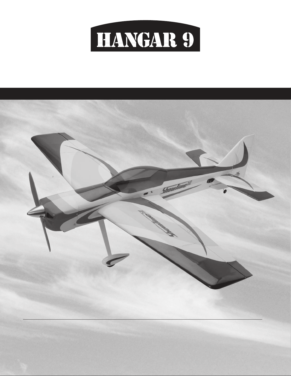
ShowTime 50 ARF
5.
ASSEMBLY MANUAL
Specifications
Wingspan ....................................... 57 in (1448mm)
Wing Area
........................... 722 sq in (46.6 sq dm)
Length ....................................... 59.25 in (1505mm)
Weight .................................... 6–7 lb (2.7kg–3.1kg)
Page 2

Table of Contents
Contents of Kit . . . . . . . . . . . . . . . . . . . . . . . . . . . . . . . . . . . . . . . . . . . . . . . . . . . . . . . . . . . . . . . . . . . .3
Radio and Power Systems Requirements
UltraCote® Covering Colors . . . . . . . . . . . . . . . . . . . . . . . . . . . . . . . . . . . . . . . . . . . . . . . . . . . . . . . . . .4
Field Equipment Required
Optional Field Equipment
Required Tools and Adhesives
Limited Warranty Period
Limited Warranty & Limits of Liability
Safety Precautions
Questions, Assistance, and Repairs
Questions or Assistance
Inspection or Repairs
Warranty Inspection and Repairs
Non-Warranty Repairs
Safety, Precautions, and Warnings
Before Starting Assembly
Using the Manual
Section 1: Aileron Installation
. . . . . . . . . . . . . . . . . . . . . . . . . . . . . . . . . . . . . . . . . . . . . . . . . . . . . . . . . . . . . . . . .5
. . . . . . . . . . . . . . . . . . . . . . . . . . . . . . . . . . . . . . . . . . . . . . . . . . . . . . . . . . . . . . . . . .7
. . . . . . . . . . . . . . . . . . . . . . . . . . . . . . . . . . . . . . . . . . . . . . . . . . . . . . . . . . . .4
. . . . . . . . . . . . . . . . . . . . . . . . . . . . . . . . . . . . . . . . . . . . . . . . . . . . . . . . . . . .4
. . . . . . . . . . . . . . . . . . . . . . . . . . . . . . . . . . . . . . . . . . . . . . . . . . . . . . . .4
. . . . . . . . . . . . . . . . . . . . . . . . . . . . . . . . . . . . . . . . . . . . . . . . . . . . . . . . . . . . .5
. . . . . . . . . . . . . . . . . . . . . . . . . . . . . . . . . . . . . . . . . . . . . . . . . . . . . . . . . . . . .5
. . . . . . . . . . . . . . . . . . . . . . . . . . . . . . . . . . . . . . . . . . . . . . . . . . . . . . . . . . . . . . .6
. . . . . . . . . . . . . . . . . . . . . . . . . . . . . . . . . . . . . . . . . . . . . . . . . . . . . . .6
. . . . . . . . . . . . . . . . . . . . . . . . . . . . . . . . . . . . . . . . . . . . . . . . . . . . . . . . . . . . . . .6
. . . . . . . . . . . . . . . . . . . . . . . . . . . . . . . . . . . . . . . . . . . . . . . . . . . . . . . . . . . .7
. . . . . . . . . . . . . . . . . . . . . . . . . . . . . . . . . . . . . . . . . . . . . . . . . . . . . . . . .8
. . . . . . . . . . . . . . . . . . . . . . . . . . . . . . . . . . . . . . . . . . . . . . . .3
. . . . . . . . . . . . . . . . . . . . . . . . . . . . . . . . . . . . . . . . . . . . . . . . . .5
. . . . . . . . . . . . . . . . . . . . . . . . . . . . . . . . . . . . . . . . . . . . . . . . . . . .5
. . . . . . . . . . . . . . . . . . . . . . . . . . . . . . . . . . . . . . . . . . . . . . . . . . . . .7
Section 2: Stabilizer Installation
Section 3: Elevator Installation
Section 4: Rudder Installation
Section 5: Landing Gear Installation
Section 6A: Four-StrokeEngine Installation
Section 6B: Two-Stroke Engine Installation
Section 7: Cowling Installation
Section 8: Final Assembly
Center of Gravity
Radio Setup
Control Throws
Rates and Expos
Range Test Your Radio
2006 Official AMA National Model Aircraft Safety Code
. . . . . . . . . . . . . . . . . . . . . . . . . . . . . . . . . . . . . . . . . . . . . . . . . . . . . . . . . . . . . . . . . .35
. . . . . . . . . . . . . . . . . . . . . . . . . . . . . . . . . . . . . . . . . . . . . . . . . . . . . . . . . . . . . . . . . . . . .35
. . . . . . . . . . . . . . . . . . . . . . . . . . . . . . . . . . . . . . . . . . . . . . . . . . . . . . . . . . . . . . . . . . .36
. . . . . . . . . . . . . . . . . . . . . . . . . . . . . . . . . . . . . . . . . . . . . . . . . . . . . . . . . . . . . . . . . .37
. . . . . . . . . . . . . . . . . . . . . . . . . . . . . . . . . . . . . . . . . . . . . . . . . . . . . . . . . . . . .37
. . . . . . . . . . . . . . . . . . . . . . . . . . . . . . . . . . . . . . . . . . . . . . . . . . . . . .13
. . . . . . . . . . . . . . . . . . . . . . . . . . . . . . . . . . . . . . . . . . . . . . . . . . . . . . .14
. . . . . . . . . . . . . . . . . . . . . . . . . . . . . . . . . . . . . . . . . . . . . . . . . . . . . . . .17
. . . . . . . . . . . . . . . . . . . . . . . . . . . . . . . . . . . . . . . . . . . . . . . . . . .22
. . . . . . . . . . . . . . . . . . . . . . . . . . . . . . . . . . . . . . . . . . . . . .24
. . . . . . . . . . . . . . . . . . . . . . . . . . . . . . . . . . . . . . . . . . . . .28
. . . . . . . . . . . . . . . . . . . . . . . . . . . . . . . . . . . . . . . . . . . . . . . . . . . . . . .31
. . . . . . . . . . . . . . . . . . . . . . . . . . . . . . . . . . . . . . . . . . . . . . . . . . . . . . . . . .33
. . . . . . . . . . . . . . . . . . . . . . . . . . . . . . . . . . . .38
2
Page 3
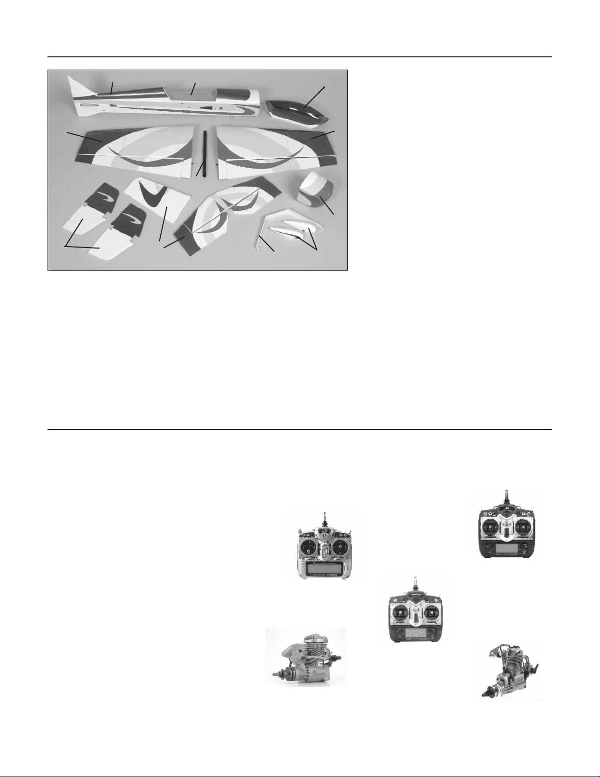
Contents of Kit
A
E
D
Replacement Parts
A. HAN4276 Fuselage w/Fin
and Hatch
B. HAN4277 Wing Set w/Ailerons
B
B
C. HAN4278 Tail Set w/Stabilizer,
Elevator and Rudder
D. HAN4279 Canopy
I
E. HAN4280 Canopy Hatch
F. HAN4281 Painted Cowl
F
G. HAN4282 Landing Gear
H. HAN4283 Wheel Pant Set
J
C
G
H
I. HAN4286 Anodized Wing Tube
J. HAN4288 Side Force
Generator Set
Items not shown
HAN4284 Decal Set
HAN4285 Tail Wheel Bracket
HAN4287 Pushrod and
Hardware Set
Radio and Power Systems Requirements
• 5- to 6-channel radio system (minimum) w/receiver
• 537 Standard Servo (JRPS537) (6) or equivalent for rudder (1), elevator (2), ailerons (2), throttle (1)
• 12" Servo Lead Extension (JRPA098) (2)
• 6" Y-Harness (JSP98020)
Recommended JR® or JR SPORT™ Systems
• XP9303
• XP7202
• XP6102
• XS600
Recommended Power Systems
• .52 2-stroke
• .82 4-stroke
JR XP9303
JR XP6102
Evolution .52NX
EVOE0520
JR XP7202
Saito .82 AAC
SAIE082A
3
Page 4

UltraCote® Covering Colors
Pearl Blue HANU845 White HANU870
True Red HANU866 Bright Yellow HANU872
Field Equipment Required
• Propeller • 4-Cycle Super Plug (HAN3011)
• Long Reach Glow Plug Wrench (HAN2510) • Metered Glow Driver w/Ni-Cd & Charger (HAN7101)
• 2-Cycle Sport Plug (HAN3001) • Fuel
• 2-Cycle Super Plug (HAN3006) • Manual Fuel Pump (HAN118)
Optional Field Equipment
• 12V 7Ah Sealed Battery (HAN102) • PowerPro™ 12V Starter (HAN161)
Required Tools and Adhesives
Tools
• Canopy scissors • Drill
• Square • Flat blade screwdriver
• Foam: 1/4" (6mm) • Hobby knife
• Side cutters • Phillips screwdriver (large)
• Phillips screwdriver (small) • Pliers
• Ruler • Sandpaper
• Hex wrench: 9/64", 3/16" • Socket wrench: 11/32"
• Drill bit: 1/16" (1.5mm), 5/64" (2mm), 3/32" (2.5mm), 1/8" (3mm), 9/64" (3.5mm), 5/32" (4mm), 1/4" (6mm)
Adhesives
• 6-minute epoxy • 30-minute epoxy
• Thin CA (cyanoacrylate) glue • Medium CA (cyanoacrylate) glue
• CA remover/debonder • Pacer Z-42 Threadlock
• Zap-A-Dap-A-Goo • Hinge glue
• Canopy glue (Formula 560) • Masking tape (3M blue recommended)
Other Required Items
• Epoxy brushes • Felt-tipped pen or pencil
• File • Measuring device (e.g. ruler, tape measure)
• Mixing sticks for epoxy • Paper towels
• Petroleum jelly • Rubbing alcohol
• Sanding bar • Sandpaper (medium)
• String • T-pins
• Wax paper • Rotary tool w/sanding drums
4
Page 5

Date of Purchase Warranty Period
Exclusive Warranty- Horizon Hobby, Inc., (Horizon) warranties that the Products purchased (the "Product") will be free
from defects in materials and workmanship at the date of purchase by the Purchaser.
Limited Warranty
(a) This warranty is limited to the original Purchaser ("Purchaser") and is not transferable. REPAIR OR REPLACEMENT
AS PROVIDED UNDER THIS WARRANTY IS THE EXCLUSIVE REMEDY OF THE PURCHASER. This warranty covers only
those Products purchased from an authorized Horizon dealer. Third party transactions are not covered by this warranty.
Proof of purchase is required for warranty claims. Further, Horizon reserves the right to change or modify this warranty
without notice and disclaims all other warranties, express or implied.
(b) Limitations- HORIZON MAKES NO WARRANTY OR REPRESENTATION, EXPRESS OR IMPLIED, ABOUT NONINFRINGEMENT, MERCHANTABILITY OR FITNESS FOR A PARTICULAR PURPOSE OF THE PRODUCT. THE
PURCHASER ACKNOWLEDGES THAT THEY ALONE HAVE DETERMINED THAT THE PRODUCT WILL SUITABLY MEET
THE REQUIREMENTS OF THE PURCHASER’S INTENDED USE.
(c) Purchaser Remedy- Horizon's sole obligation hereunder shall be that Horizon will, at its option, (i) repair or (ii)
replace, any Product determined by Horizon to be defective. In the event of a defect, these are the Purchaser's exclusive
remedies. Horizon reserves the right to inspect any and all equipment involved in a warranty claim. Repair or replacement
decisions are at the sole discretion of Horizon. This warranty does not cover cosmetic damage or damage due to acts of
God, accident, misuse, abuse, negligence, commercial use, or modification of or to any part of the Product. This warranty
does not cover damage due to improper installation, operation, maintenance, or attempted repair by anyone other than
Horizon. Return of any goods by Purchaser must be approved in writing by Horizon before shipment.
Damage Limits
HORIZON SHALL NOT BE LIABLE FOR SPECIAL, INDIRECT OR CONSEQUENTIAL DAMAGES, LOSS OF PROFITS OR
PRODUCTION OR COMMERCIAL LOSS IN ANY WAY CONNECTED WITH THE PRODUCT, WHETHER SUCH CLAIM
IS BASED IN CONTRACT, WARRANTY, NEGLIGENCE, OR STRICT LIABILITY. Further, in no event shall the liability of
Horizon exceed the individual price of the Product on which liability is asserted. As Horizon has no control over use,
setup, final assembly, modification or misuse, no liability shall be assumed nor accepted for any resulting damage or
injury. By the act of use, setup or assembly, the user accepts all resulting liability.
If you as the Purchaser or user are not prepared to accept the liability associated with the use of this Product, you are
advised to return this Product immediately in new and unused condition to the place of purchase.
Law: These Terms are governed by Illinois law (without regard to conflict of law principals).
Safety Precautions
This is a sophisticated hobby Product and not a toy. It must be operated with caution and common sense and requires
some basic mechanical ability. Failure to operate this Product in a safe and responsible manner could result in injury
or damage to the Product or other property. This Product is not intended for use by children without direct adult
supervision. The Product manual contains instructions for safety, operation and maintenance. It is essential to read
and follow all the instructions and warnings in the manual, prior to assembly, setup or use, in order to operate correctly
and avoid damage or injury.
5
Page 6

Questions, Assistance, and Repairs
Your local hobby store and/or place of purchase cannot provide warranty support or repair. Once assembly, setup or
use of the Product has been started, you must contact Horizon directly. This will enable Horizon to better answer your
questions and service you in the event that you may need any assistance. For questions or assistance, please direct your
email to [email protected], or call 877.504.0233 toll free to speak to a service technician.
Inspection or Repairs
If this Product needs to be inspected or repaired, please call for a Return Merchandise Authorization (RMA). Pack
the Product securely using a shipping carton. Please note that original boxes may be included, but are not designed
to withstand the rigors of shipping without additional protection. Ship via a carrier that provides tracking and insurance
for lost or damaged parcels, as
at our facility. A Service Repair Request is available at www.horizonhobby.com on the “Support” tab. If you do not
have internet access, please include a letter with your complete name, street address, email address and phone number
where you can be reached during business days, your RMA number, a list of the included items, method of payment
for any non-warranty expenses and a brief summary of the problem. Your original sales receipt must also be included
for warranty consideration. Be sure your name, address, and RMA number are clearly written on the outside of the
shipping carton.
Horizon is not responsible for merchandise until it arrives and is accepted
Warranty Inspection and Repairs
To receive warranty service, you must include your original sales receipt verifying the proof-of-purchase
date. Provided warranty conditions have been met, your Product will be repaired or replaced free of charge. Repair or
replacement decisions are at the sole discretion of Horizon Hobby.
Non-Warranty Repairs
Should your repair not be covered by warranty the repair will be completed and payment will be
required without notification or estimate of the expense unless the expense exceeds 50% of the retail
purchase cost. By submitting the item for repair you are agreeing to payment of the repair without notification. Repair
estimates are available upon request. You must include this request with your repair. Non-warranty repair estimates will
be billed a minimum of ½ hour of labor. In addition you will be billed for return freight. Please advise us of your preferred
method of payment. Horizon accepts money orders and cashiers checks, as well as Visa, MasterCard, American Express,
and Discover cards. If you choose to pay by credit card, please include your credit card number and expiration date. Any
repair left unpaid or unclaimed after 90 days will be considered abandoned and will be disposed of accordingly.
note: non-warranty repair is only available on electronics and model engines.
Electronics and engines requiring inspection or repair should be shipped to the following address:
Horizon Service Center
4105 Fieldstone Road
Champaign, Illinois 61822
Please
All other Products requiring warranty inspection or repair should be shipped to the following address:
Horizon Product Support
4105 Fieldstone Road
Champaign, Illinois 61822
Please call 877-504-0233 with any questions or concerns regarding this product or warranty.
6
Page 7
Safety, Precautions, and Warnings
This model is controlled by a radio signal that is subject to interference from many sources outside your control. This
interference can cause momentary loss of control so it is advisable to always keep a safe distance in all directions around
your model, as this margin will help to avoid collisions or injury.
• Always operate your model in an open area away from cars, traffic, or people.
• Avoid operating your model in the street where injury or damage can occur.
• Never operate the model into the street or populated areas for any reason.
• Never operate your model with low transmitter batteries.
• Carefully follow the directions and warnings for this and any optional support equipment (chargers, rechargeable
battery packs, etc.) that you use.
• Keep all chemicals, small parts and anything electrical out of the reach of children.
• Moisture causes damage to electronics. Avoid water exposure to all equipment not specifically designed and protected
for this purpose.
Before Starting Assembly
Before beginning the assembly of the ShowTime™ 50, remove each part from its bag for inspection. Closely inspect
the fuselage, wing panels, rudder, and stabilizer for damage. If you find any damaged or missing parts, please contact
the place of purchase.
If you find any wrinkles in the covering, use a heat gun or sealing iron to remove them. Use caution while working around
areas where the colors overlap to prevent separating the colors.
Using the Manual
HAN101 – Sealing Iron
HAN141 – Sealing Iron
Sock
This manual is divided into sections to help make assembly easier to understand, and to provide breaks between each
major section. In addition, check boxes have been placed next to each step to keep track of each step completed. Steps
with a single box (
repeating, such as for a right or left wing panel, two servos, etc. Remember to take your time and follow the directions.
) are performed once, while steps with two boxes ( ) indicate that the step will require
HAN100 – Heat Gun
HAN150 – Covering Glove
7
Page 8
Section 1: Aileron Installation
Required Parts
• Wing panel (left and right) • Aileron (left and right)
• CA hinge (8) • Nylon wire keeper (2)
• Nylon clevis (2) • Clevis retainer (2)
• Control horn w/backplate
• 2-56 x 1
3
• 4
3
/16" machine screw (6)
/8" (110mm) pushrod (2)
Required Tools and Adhesives
• Thin CA • T-pins
• Felt-tipped pen • Drill
• Square • Ruler
• Servo w/hardware (2) • Side cutters
• 12" Servo Extension (JRPA098)
• Drill bit: 1/16" (1.5mm), 5/64" (2mm)
• Phillips screwdriver (small)
• Large Servo Horns w/Screws (JRPA212) (2)
We recommend that you use the
hinges provided. They work extremely
well when installed as described.
Even though the ailerons are large,
we had absolutely no problems.
Step 2
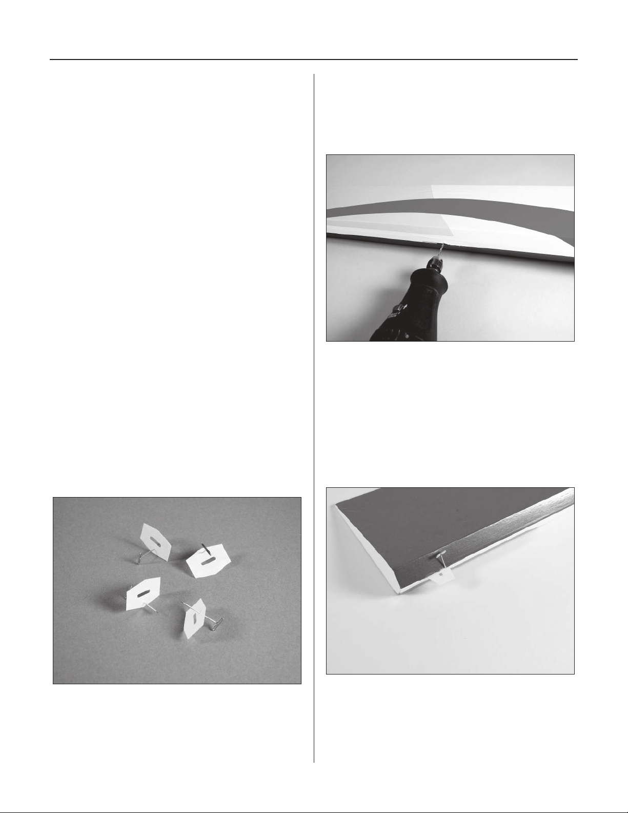
Use a 1/16" (1.5mm) drill bit to drill a hole in the center
of each hinge location in both the wing and aileron. This
creates a tunnel that the CA can pass through allowing the
CA to penetrate further into the hinge.
Note: Using a rotary tool and 1/16" (1.5mm)
drill bit will make the perfect hole as it
removes the excess wood fibers from the hole.
Step 3
Step 1
Locate 4 CA hinges. Place a T-pin in the center of
the hinges.
Place the hinges in the precut slots in the aileron (or wing
if you prefer). Each T-pin will rest against the edge when
installed correctly.
8
Page 9
Section 1: Aileron Installation
Step 4
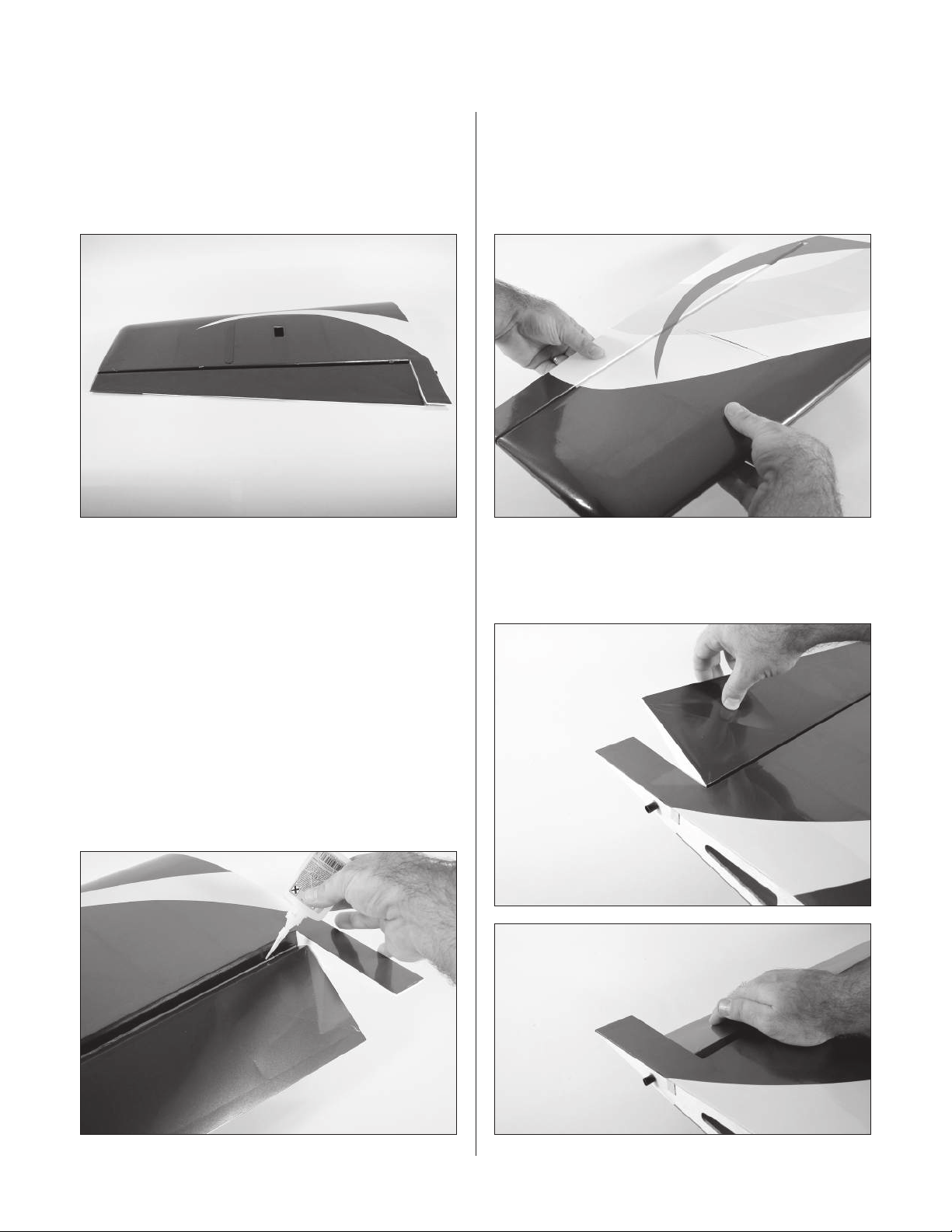
Slide the aileron and wing together. The gap between the
aileron and wing should be approximately 1/64" (.4mm).
Align the end of the aileron to the wing. Also check that
the aileron can move freely and not bind at the wing root.
Note: Do not use CA accelerator during
the hinging process. The CA must be
allowed to soak into the hinge to provide
the best bond. Using accelerator will not
provide enough time for this process.
Step 6
Firmly grasp the wing and aileron and gently pull on the
aileron to ensure the hinges are secure and cannot be
pulled apart. Use caution when gripping the wing and
aileron to avoid crushing the structure.
Step 7
Work the aileron up and down several times to work in the
hinges and check for proper movement.
Step 5
Remove the T-pins from the hinges. Flex the aileron and
apply Thin CA to each hinge. Make sure the hinge is fully
saturated with CA. Use a paper towel and CA remover/
debonder to clean up any excess CA from the wing and/or
aileron. Make sure to apply CA to both the top and bottom
of the hinge.
9
Page 10
Section 1: Aileron Installation
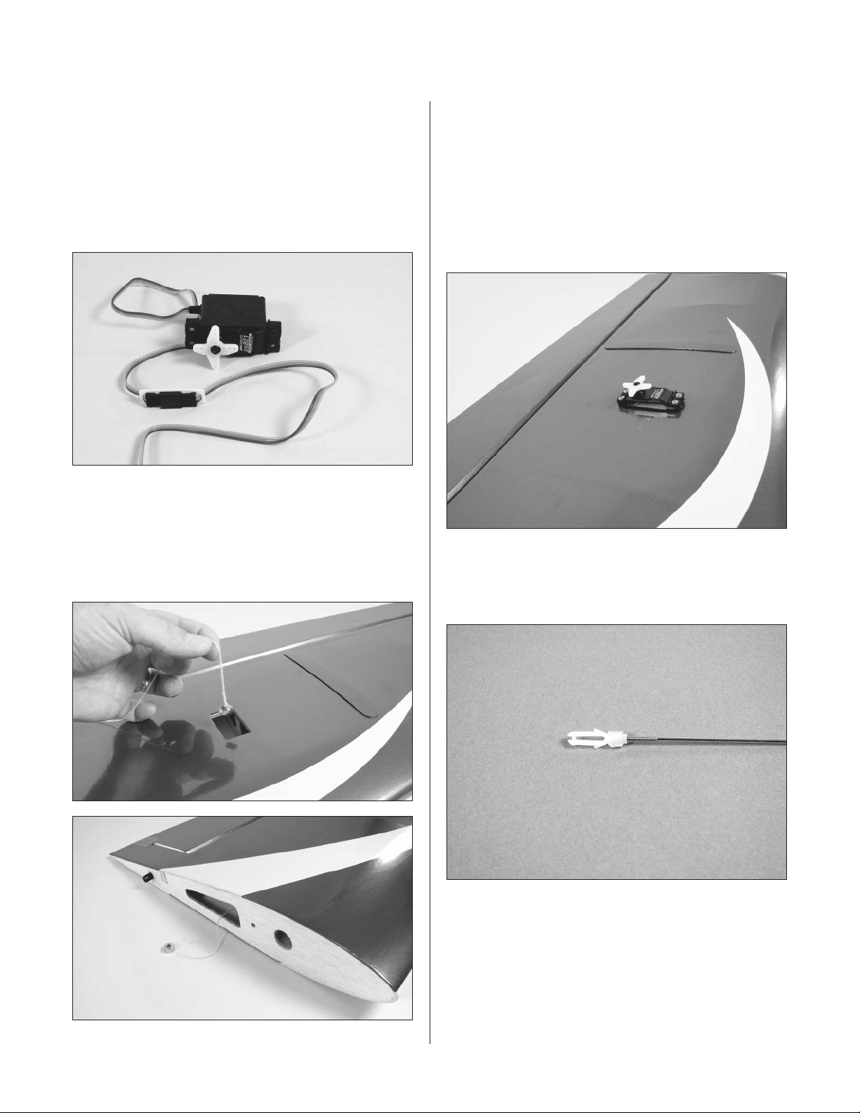
Step 8
Install the servo hardware (grommets and eyelets)
included with the servo. Plug a 12" servo extension onto
the servos. Either tie the servo leads together, using a
commercially available connector, or use unwaxed dental
floss to secure the extensions to prevent them from
coming loose during flight.
Step 9
Step 10
Insert the servo into the opening in the wing. Use the
string to pull the servo lead through the wing. Make
sure the servo lead exits the root of the wing as shown.
Position the servo so the output shaft is toward the trailing
edge of the wing. Use a 1/16" (1.5mm) drill bit to drill the
locations for the servo screws. Mount the servos using the
hardware provided with them.
Tie a weight to a piece of string. A wheel collar works
great in this application. Lower the string into the wing
from the aileron servo opening. Let the weight drop out
through the wing root for the servo.
Step 11
Slide a clevis retainer onto a nylon clevis. Thread a clevis
onto a 4
3
/8" (110mm) wire a minimum of 10 turns.
10
Page 11

Section 1: Aileron Installation
Step 12
Remove the back plate from a control horn using side
cutters or a sharp hobby knife. Attach the clevis to the
control horn. After installing a heavy-duty servo arm,
position the control horn on the aileron so the horn aligns
with the hinge line of the aileron. With the aileron servo
centered, position the pushrod so it is perpendicular to the
hinge line as it crosses the servo arm. Mark the position
for the mounting holes using a felt-tipped pen.
Step 14
Attach the control horn using three #2 x 1
the control horn backplate.
3
/16" screws and
Step 13
Drill three 5/64" (2mm) holes at the locations marked in
the previous step.
11
Page 12
Section 1: Aileron Installation
Step 15
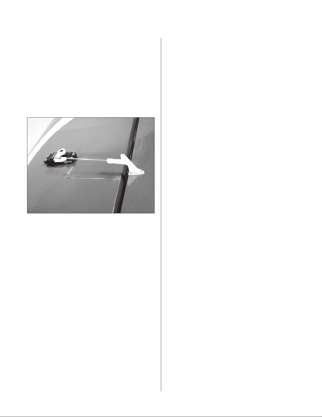
Center the aileron servo electronically using the radio
system. Install a servo arm onto the aileron servo. Attach
the pushrod with clevis to the control horn. Physically
place the aileron control surface in neutral. Mark the
pushrod where it crosses the holes in the servo arm. Bend
the wire 90 degrees at the mark made in the previous step.
Cut the wire 1/2" (13mm) above the bend. Slide the wire
through the outer hole in the aileron servo arm. Secure the
wire using a nylon wire keeper.
Note: Remove the excess arm from the
servo horn using side cutters to prevent
interference between it and the linkage.
Step 16
Repeat Steps 1 through 15 for the remaining aileron.
Note: Once the ailerons have been
installed, it is suggested to seal the hinge
gap from the bottom of the aileron using
either clear tape or clear covering.
12
Page 13
AA
A=A
Parallel
Section 2: Stabilizer Installation
Required Parts
• Wing panel (right and left) • Fuselage
• Horizontal stabilizer
• 1/4-20 x 2" nylon bolt (2) • Wing tube
Required Tools and Adhesives
• 30-minute epoxy • Sandpaper
• Ruler • Epoxy brush
• Masking tape
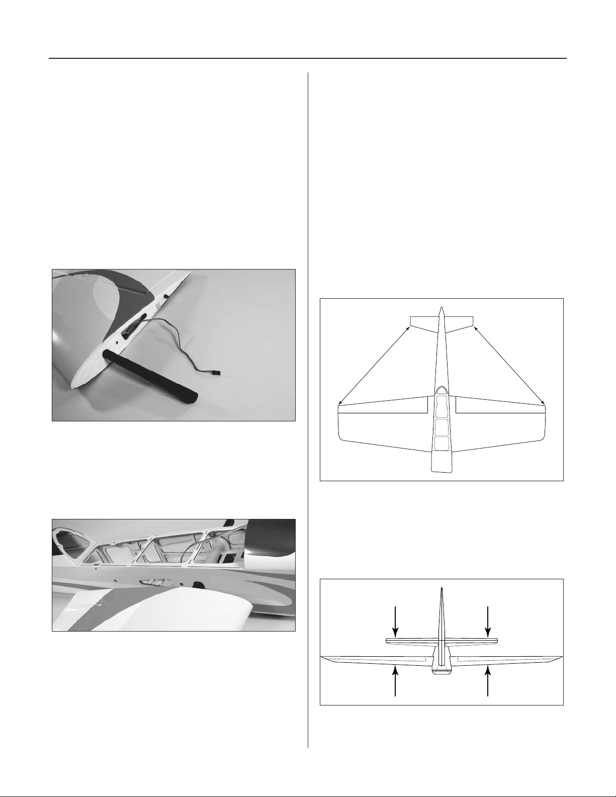
Step 1
Locate the wing tube and carefully slide it into one
wing panel.
Step 4
Slide the stab into the fuselage. Center the stab in the
opening by measuring the distance from the fuselage
to each tip. The stab is aligned when both measurements
are identical.
Hint: The stabilizers can be installed
temporarily to aid in getting the stabilizer
centered in the fuselage. Just don’t glue
the hinges so they can be removed
once the stabilizer is aligned.
Step 5
Check the distance from each stab tip to each wing tip.
These measurements must be equal.
Step 2
Remove the hatch from the fuselage. Slide the wing
against the fuselage, guiding the alignment pin of the
wing into the location in the fuselage. Secure the wing
to the fuselage using a 1/4-20 x 2" bolt.
Step 3
Slide the remaining wing panel onto the wing tube and
secure it to the fuselage using a 1/4-20 x 2" wing bolt.
Step 6
The last alignment step is making sure the wing and
stabilizer are parallel. If they are not, sand the opening
in the fuselage for the stab until the stab rests parallel
to the wing.
13
Page 14
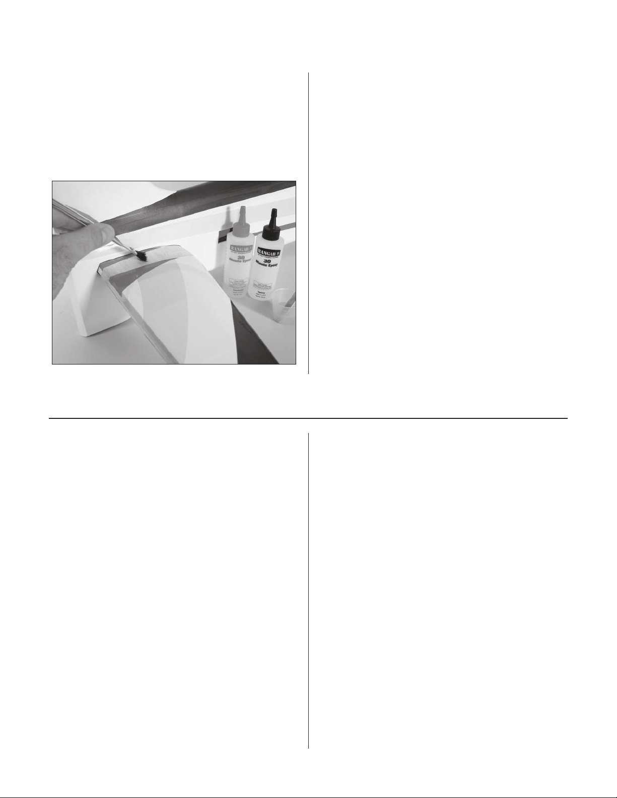
Section 2: Stabilizer Installation
Step 7
Mix 1/2 ounce of 30-minute epoxy. Apply epoxy to the top
and bottom of the exposed wood of the stabilizer. Slide the
stabilizer the rest of the way into the slot in the fuselage.
Double-check the alignment to verify it is correct. Remove
any excess epoxy using a paper towel and rubbing
alcohol. Allow the epoxy to fully cure before continuing.
Hint: Use rubbing alcohol and a paper towel
to clean up any excess epoxy. Remember,
this only works before the epoxy cures.
Section 3: Elevator Installation
Required Parts
• Fuselage • CA hinge (6)
• Elevator (right and left)
Required Tools and Adhesives
• Drill • Thin CA
• 2mm x 16mm (6) • Dental floss or string
• T-pins
• 18" Servo Extensions (JRPA099) (2)
• Drill bit: 1/16" (1.5mm) 3/32" (2.5mm)
• Large Servo Horns w/Screws (JRPA212) (2)
• Reversing Y-Harness (JRPA133) (Optional)
Step 1
Install an 18" servo extension on one of the servos.
Either tie the leads together, use a commercially
available connector, or use unwaxed dental floss to
secure the leads to prevent them from coming loose
during flight. Also install the servo hardware (grommets
and eyelets) at this time.
Note: Using two standard rotation servos
and a standard Y-harness for the elevator
servos will result in them moving in opposite
directions instead of the same direction. As
such, the elevator servo installation will either
require the use of one reversed rotation servo
and one standard rotation servo or a reversing
Y-harness. It is highly recommended to use a
computer radio or a JR
the two elevator servos to operate properly.
®
MatchBox™ to link
14
Page 15
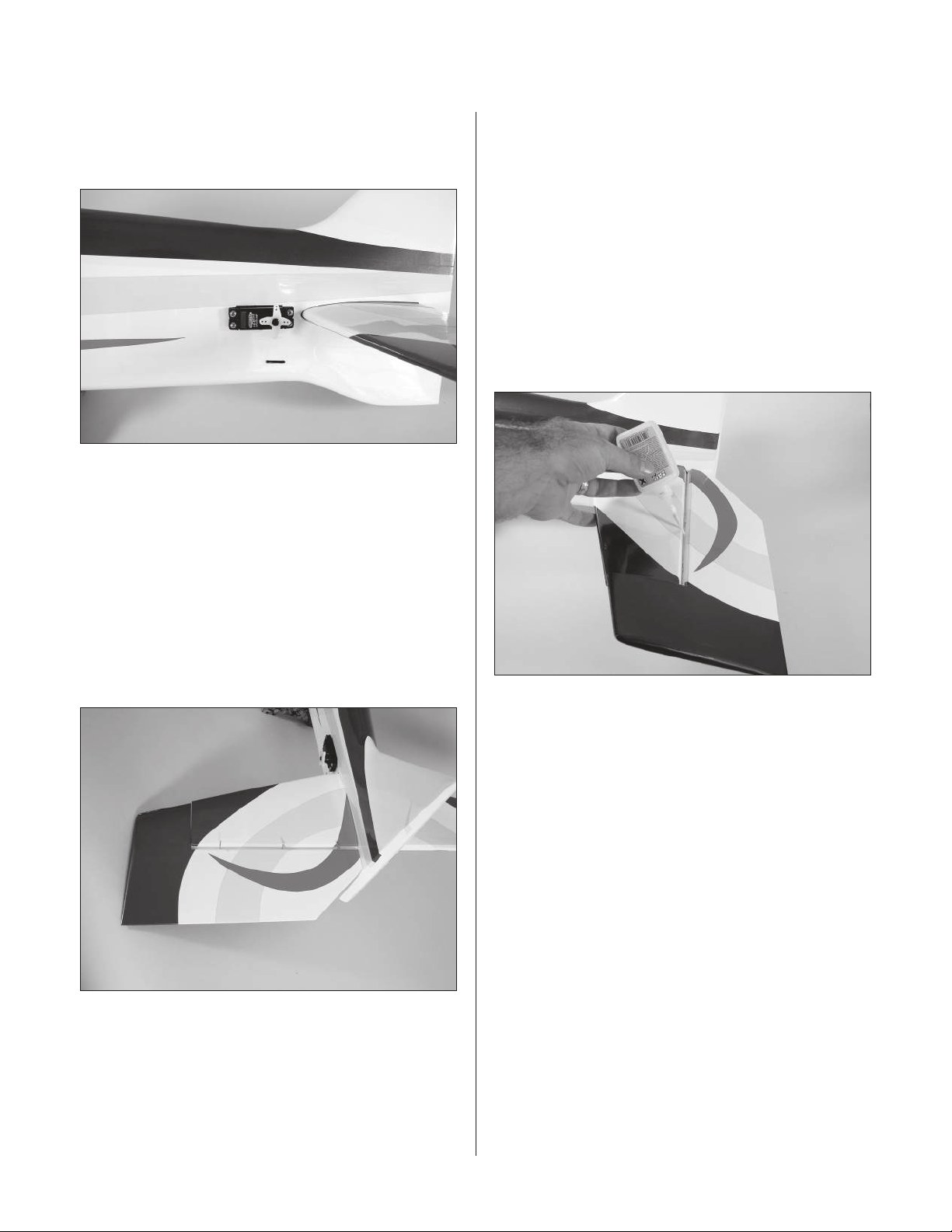
Section 3: Elevator Installation
Step 2
Fasten the elevator servo in place using the screws
included with the servo.
Step 3
Locate 3 CA hinges. Place a T-pin in the center of the
hinges. Use a 1/16" (1.5mm) drill bit to drill a hole in the
center of each hinge location in both the wing and aileron.
Place the hinges in the precut slots in the stabilizer. Each
T-pin will rest against the edge when installed correctly.
Slide the stabilizer and elevator together. The gap between
the between the two should be approximately 1/64"
(.4mm). Align the stabilizer so it can move freely and not
bind against the stabilizer.
Step 4
Remove the T-pins from the hinges. Flex the elevator and
apply Thin CA to each hinge. Make sure the hinge is fully
saturated with CA. Use a paper towel and CA remover/
debonder to clean up any excess CA from the stabilizer
and/or elevator. Make sure to apply CA to both the top
and bottom of the hinge. Firmly grasp the stabilizer and
elevator and gently pull on the elevator to ensure the
hinges are secure and cannot be pulled apart. Use caution
when gripping the stabilizer and elevator to avoid crushing
the structure. Work the elevator up and down several times
to work in the hinges and check for proper movement.
Step 5
Note: Do not use CA accelerator during
the hinging process. The CA must be
allowed to soak into the hinge to provide
the best bond. Using accelerator will not
provide enough time for this process.
Slide a clevis retainer onto a nylon clevis. Thread a clevis
onto a 6" (152mm) wire a minimum of 10 turns.
15
Page 16
Section 3: Elevator Installation
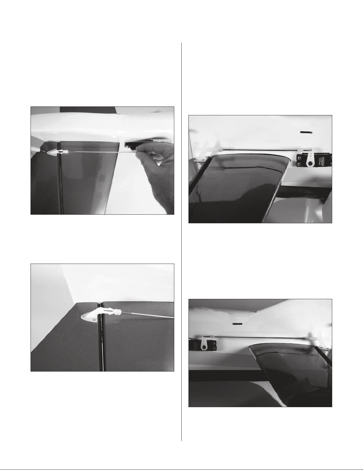
Step 6
Remove the back plate from a control horn using side
cutters or a sharp hobby knife. Attach the clevis to the
control horn. After installing a heavy-duty servo arm,
position the control horn on the elevator so the linkage
is parallel to the outside edge of the fuselage. Mark the
position for the mounting holes using a felt-tipped pen.
Step 8
Center the elevator servo electronically using the radio
system. Physically place the elevator control surface in
neutral. Mark the pushrod where it crosses the holes in
the servo arm. Bend the wire 90 degrees at the mark made
in the previous step. Cut the wire 1/2" (13mm) above the
bend. Slide the wire through the outer hole in the elevator
servo arm. Secure the wire using a nylon wire keeper.
Step 7
Drill three 5/64" (2mm) holes at the locations marked
in the previous step.Attach the control horn using three
3
#2 x 1
/16" screws and the control horn backplate.
Note: Remove the excess arm from the
servo horn using side cutters to prevent
interference between it and the linkage.
Step 9
Repeat Steps 1 through 8 for the remaining elevator and
servo. Use the 8" (200mm) wire to assemble the linkage.
16
Page 17
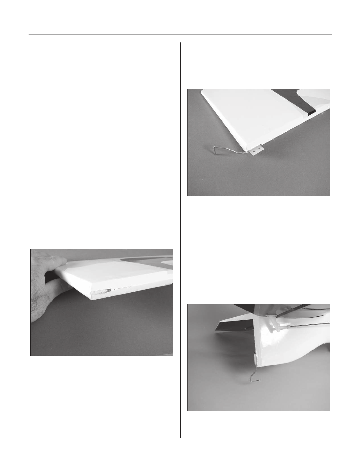
Section 4: Rudder Installation
Required Parts
• Fuselage assembly • Rudder
• Tail wheel assembly
• 4-40 x 5" (127mm) threaded rod
• 1" (25mm) tail wheel
• 5/64" wheel collar w/setscrew (2)
Required Tools and Adhesives
• CA hinge (3) • T-pins
• Hobby knife • Thin CA
• 6-minute epoxy • Petroleum jelly
• Drill
• Drill bit: 1/16" (1.5mm) 1/8" (3mm)
• Hex wrench (included in kit)
• Large Servo Horn w/Screws (JRPA212)
Step 1
Make a mark 1" (25mm) from the bottom of the rudder.
Drill the location using a 1/8" (3mm) drill bit. Make
sure the drill is perpendicular to the hinge line of the
rudder. Cut a groove from the hole to the bottom of
the rudder. This is necessary to provide clearance for
the tail wheel bearing.
Step 2
Test fit the tail wheel bracket into the rudder. Make
sure there is plenty of clearance for the bracket bushing
and the hole has been drilled deep enough to fit the
tail wheel wire.
Step 3
Cut a slot in the aft end of the fuselage for the tail wheel
bearing using a hinging tool or hobby knife. Position the
top of the slot 1" (25mm) from the bottom of the fuselage.
The slot should be 7/8" (23mm) long, which is the length
of the tail wheel bearing.
Hint: An 11/64" (4.5mm) drill bit can be
used to size the notch perfectly to the nylon
bushing of the tail wheel assembly.
Step 4
Test fit the tail wheel bearing into the slot. Make the slot
large enough that the bushing will fit without forcing the
wood apart.
17
Page 18
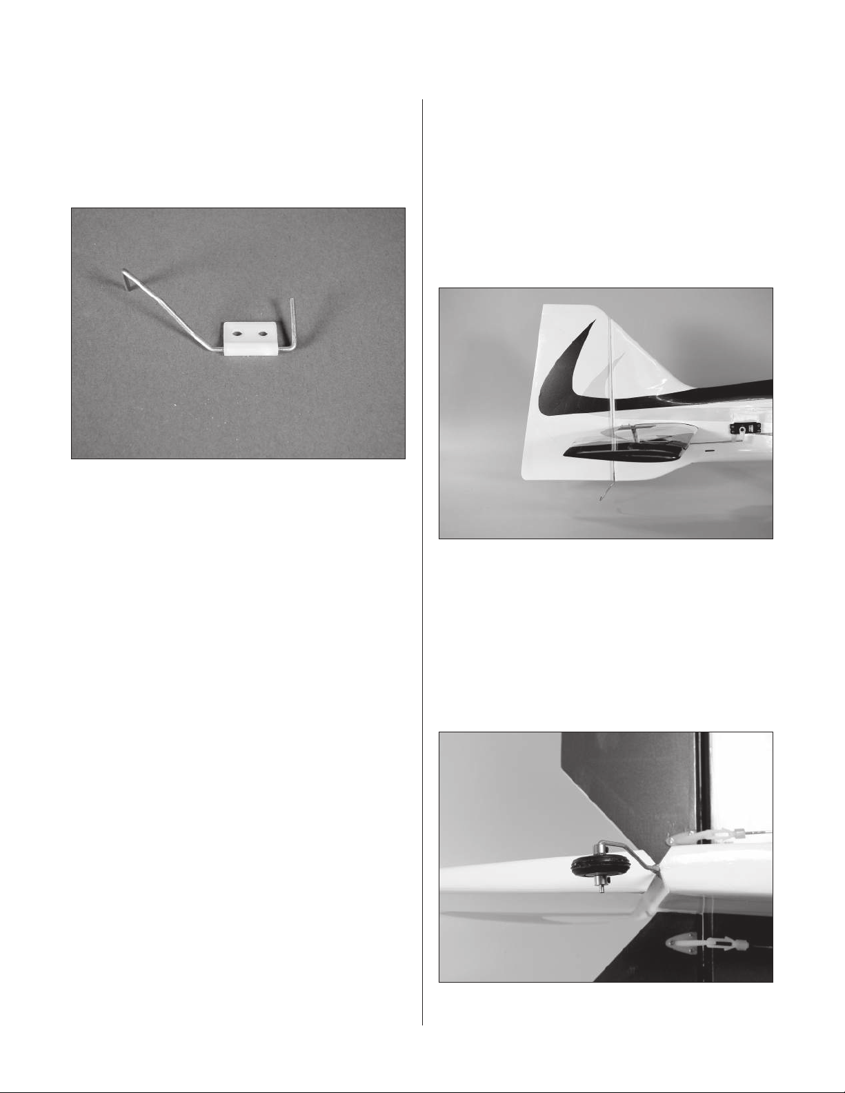
Section 4: Rudder Installation
Step 5
Apply a light coat of petroleum jelly onto the tail gear wire
where the bearing will ride. This is done to prevent the
epoxy from sticking to the wire and bearing, which would
make it a little difficult to steer or even use the rudder.
Step 6
Step 7
Fit the rudder back onto the fuselage, making sure the tail
wheel can move without binding. Check to make sure the
rudder moves freely. It should not rub against the fin at the
tip. Use 6-minute epoxy to glue the tail gear wire into the
hole drilled into the rudder. Apply thin CA to both sides of
the hinge. Make sure to saturate the hinge, and don’t use
accelerator. Use a paper towel and CA debonder/remover
to clean up any excess CA.
Mix 1/2 ounce of 6-minute epoxy and apply it to both the
tail gear bearing and the slot in the fuselage. Install the
bearing into the fuselage. Use a paper towel and rubbing
alcohol to remove any excess epoxy from the tail gear
wire, bushing, and fuselage.
Hint: You can combine the previous step with
the following step if you like. This will hold
the rudder in position while the epoxy cures.
Step 8
Once the CA and epoxy has fully cured, give the rudder
and fin the tug test to make sure the hinges are well glued.
Flex the rudder a few times to break in the hinges.
Step 9
Attach the tail wheel to the tail wheel assembly using
two 5/64" wheel collars.
18
Page 19
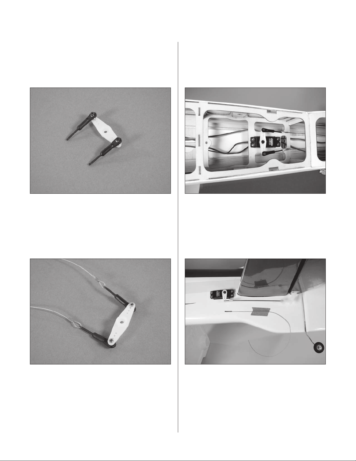
Section 4: Rudder Installation
Step 10
Use a large servo horn and attach the ball links to the
horn using the hardware included with the links. Thread
the threaded cable ends about halfway into the ball links
to complete the step.
Step 11
Step 12
Install the rudder servo into the fuselage using the
hardware provided with the servo. Use the radio system
to electronically center the rudder servo. Attach the servo
arm to the rudder servo.
Step 13
Cut the cable into two equal pieces. Attach the pull-pull
cable to the threaded cable ends using the cable, threaded
cable end and crimp. The cable passes through the crimp,
through the threaded end, then back through the crimp.
Use a crimping tool to complete the job.
Pass the cable out through the openings in the rear
of the fuselage. The cables will cross inside the fuselage
to get the correct geometry. Tape the cables to the outside
of the fuselage to prevent them from falling back into
the fuselage.
Hint: Insert a piece of music wire
into the cable openings at the rear
of the fuselage and use it to pull the
cables out through the openings.
19
Page 20
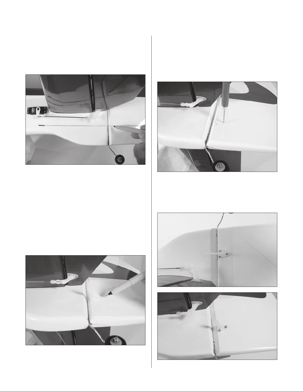
Section 4: Rudder Installation
Step 14
Position the cable so it is centered in the opening. Use a
felt-tipped pen to mark the rudder where the cable crosses
onto it. This will be used for positioning the control horns.
Mark both sides of the rudder.
Step 15
Carefully measure the location of the marks vertically on
both sides of the rudder. If they are in different locations,
split the difference and remark the rudder so both sides
are in exactly the same position vertically.
Step 17
Use a 5/64" (2mm) drill bit to drill the locations for
the screws. Drill each side half-way through the rudder
so they connect in the center. To complete the procedure,
use the drill bit to connect the holes from both sides of
the rudder.
Step 18
Attach the rudder control horns using three 2-56 x 1
machine screws and three 2-56 nuts. Use threadlock on
thin CA to prevent the nuts from vibrating loose.
3
/16"
Step 16
Position the control horn on the rudder. Mark the
locations for the screws onto the rudder using a
felt-tipped pen. Mark both sides of the rudder for the
control horn mounting screws.
20
Page 21
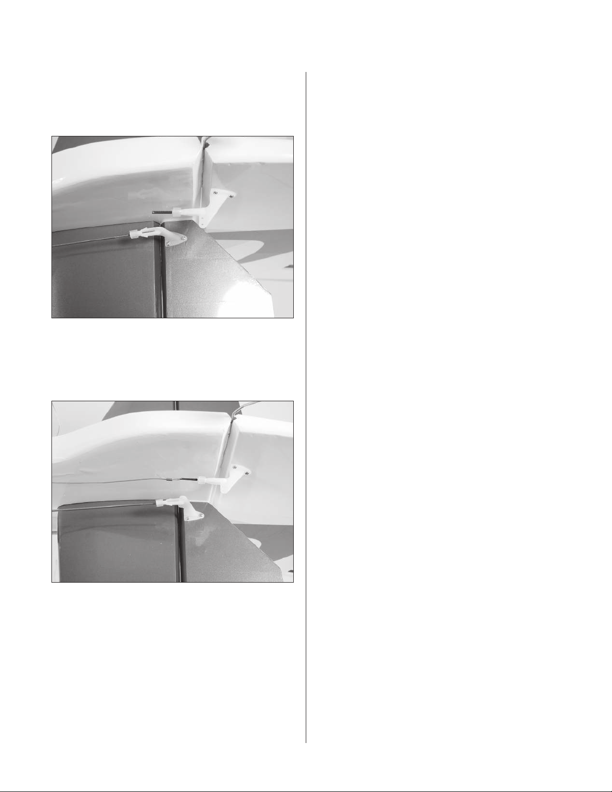
Section 4: Rudder Installation
Step 19
Plave a clevis retainer onto a nylon clevis, then thread a
threaded cable end into the clevis. Attach the clevis to the
rudder control horn. Repeat for both sides of the rudder.
Step 20
Slide a crimp onto the cable, then pass the cable through
the threaded cable end. Pass the wire back through the
crimp, but do not secure the wire until the next step.
Step 21
With the radio on, check the operation of the rudder.
Adjust the cables so when the rudder servo is centered,
the rudder is centered as well. There will be slight
tension on the cables to prevent the rudder from
wandering. Adjustments can be made at the rudder
control horn and at the servo arm. Once satisfied with
the cable lengths and tensions, use crimping pliers to
secure the cables.
Note: Check the tension of the rudder
cables before every flying session,
as they may stretch over time.
21
Page 22
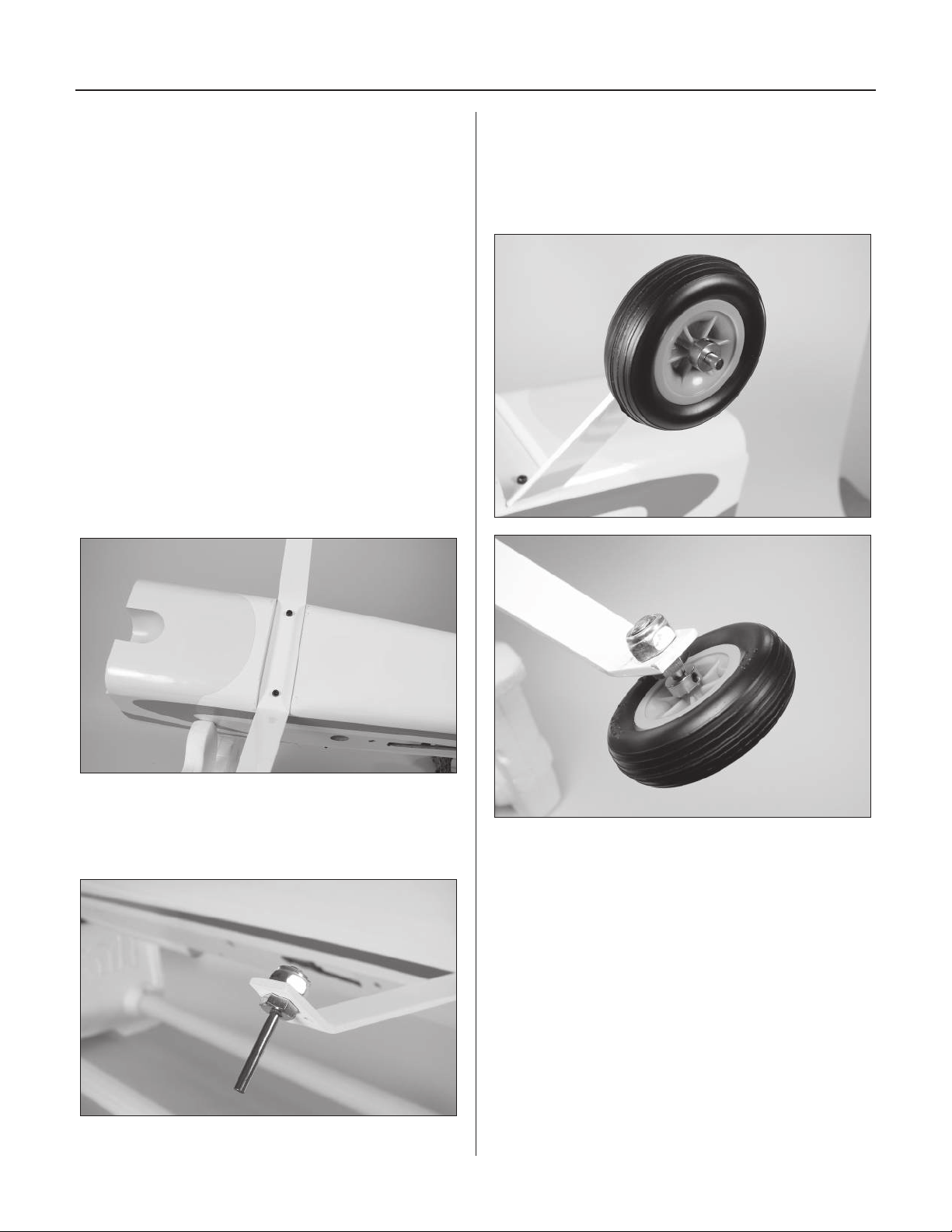
Section 5: Landing Gear Installation
Required Parts
• Fuselage • Landing gear
1
• 1
/4" axle w/nut (2) • 4-40 blind nut (4)
• 8-32 x 1/2" screw (2) • #4 washer (2)
1
• 2
/4" wheel (2)
• 4-40 x 1/2" socket head screw (4)
• 5/32" wheel collar w/setscrew (4)
Required Tools and Adhesives
• Phillips screwdriver • Hobby knife
• Adjustable wrench (small) • 3/32" hex wrench
• Drill
• Drill bit: 9/64" (3.5mm), 5/32" (4mm)
Step 1
Install the landing gear using two 8-32 x 1/2" screws.
Note that one edge of the gear is straight and the other is
at a slight angle. The straight side faces forward.
Step 3
Attach the wheel to the axle using two 5/32" wheel collars
and setscrews. Face the setscrews toward the bottom
of the wheel pant so the position of the wheel can be
adjusted once the wheel pant has been installed.
Step 2
Install an axle onto the landing gear. Secure the axle using
an adjustable wrench and the nut provided with the axle.
22
Page 23
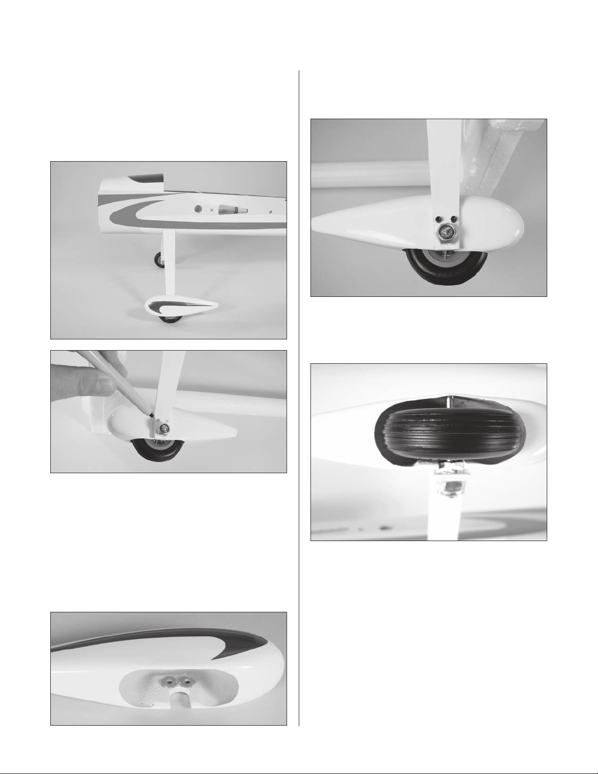
Section 5: Landing Gear Installation
Step 4
Place the airplane on the work surface. Slide the wheel
pant into position. Adjust it so it won’t interfere with the
runway while the plane is at rest. Use a felt-tipped marker
to mark the locations for the two screws through the
landing gear.
Step 6
Attach the wheel pant to the landing gear using two
4-40 x 1/2" socket head screws.
Step 7
Position the wheel so it is centered in the wheel pant.
Tighten the collars once the wheel has been positioned.
Note: It may be necessary to open
the notch in the wheel pant slightly
to fit over the hex on the axle.
Step 5
Drill the locations for the pant screws using a 9/64"
(3.5mm) drill bit. Insert two 4-40 blind nuts into the
holes from the inside of the wheel pant.
Step 8
Repeat Steps 2 through 7 for the other wheel pant.
23
Page 24
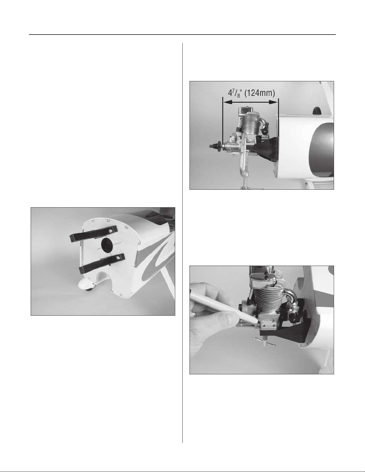
Section 6A: Four-Stroke Engine Installation
Required Parts
• Fuselage assembly • Engine mount (2)
• Clevis • Clevis retainer
• 8-32 x 1" screw (4)
•#8 x 5/8" self-tapping screw (4)
• 12" (305mm) outer pushrod tube
• 13" (330mm) pushrod wire
• Fuel tank assembly
Required Tools and Adhesives
• Drill • Clamp
• Phillips screwdriver (large) • Engine
• Medium CA • Sandpaper
• Drill bit: 5/32" (4mm), 7/64" (2.5mm)
Step 1
Attach the engine mount to the firewall using four
8-32 x 1" machine screws.
Step 2
Position the engine on the mount. Adjust the engine so
the distance from the firewall to the drive washer is 4
(124mm). Use clamps to hold the engine in position.
Note: Check to see which direction the needle
valve is pointing. It should point toward the
bottom of the aircraft. Remove the carburetor
and rotate it so it faces the bottom if necessary.
7
/8"
Step 3
Mark the locations for the engine mounting bolts.
24
Page 25
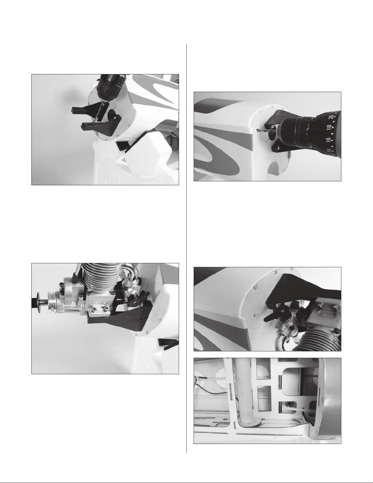
Section 6A: Four-Stroke Engine Installation
Step 4
Remove the engine and drill the locations marked in the
previous step using an 7/64" (2.5mm) drill bit.
Hint: Use a drill press for the best
results. This makes holes perfectly
perpendicular (square) to the mount.
Step 5
Attach the engine using four #8 x 5/8" socket head
self-tapping screws.
Step 6
Determine the proper location for the throttle pushrod.
Mark the location with a felt-tipped pen. Remove the
engine and drill the firewall for the pushrod tube using
a drill and 5/32" (4mm) drill bit.
Step 7
Test fit the 12" (305mm) outer pushrod tube through the
firewall and into the fuselage. Once satisfied with the fit,
roughen the tube using sandpaper. Slide the tube back
into position and use medium CA to glue it to the firewall.
Allow 1/16" (1.5mm) of the pushrod to extend forward of
the firewall. Trim the throttle pushrod at the front edge of
the throttle servo tray.
25
Page 26
Section 6A: Four-Stroke Engine Installation
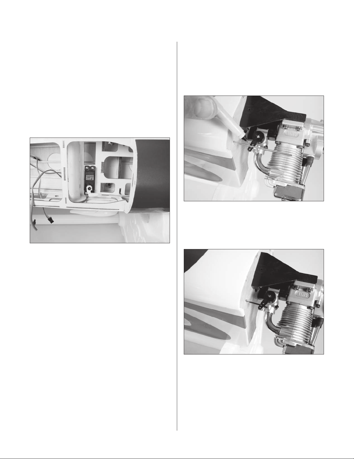
Step 8
Install the servo hardware (grommets and eyelets)
included with the servo. Mount the throttle servo with
the output shaft toward the pushrod tube. Slide a clevis
retainer onto a nylon clevis. Thread a clevis onto the
13" (330mm) pushrod wire a minimum of 10 turns.
Slide the pushrod into place from inside the fuselage
and attach the clevis to the servo arm. With the radio
on and the throttle servo plugged in, center the throttle
trim and stick. Use the screw from the servo to secure
the horn to the servo.
Step 9
Physically move the carburetor to the closed position.
Use the radio to move the throttle servo to the low
position. Mark the pushrod where it crosses the throttle
arm using a felt-tipped pen. Remove the pushrod and
make a “Z” bend in pushrod.
Note: Remove any extra arms from the servo
horn that may bind against the linkage.
Step 10
Remove the clevis from the pushrod. Slide the pushrod
into the pushrod tube from the firewall. Attach the “Z”
bend to the carburetor arm.
26
Page 27
Section 6A: Four-Stroke Engine Installation
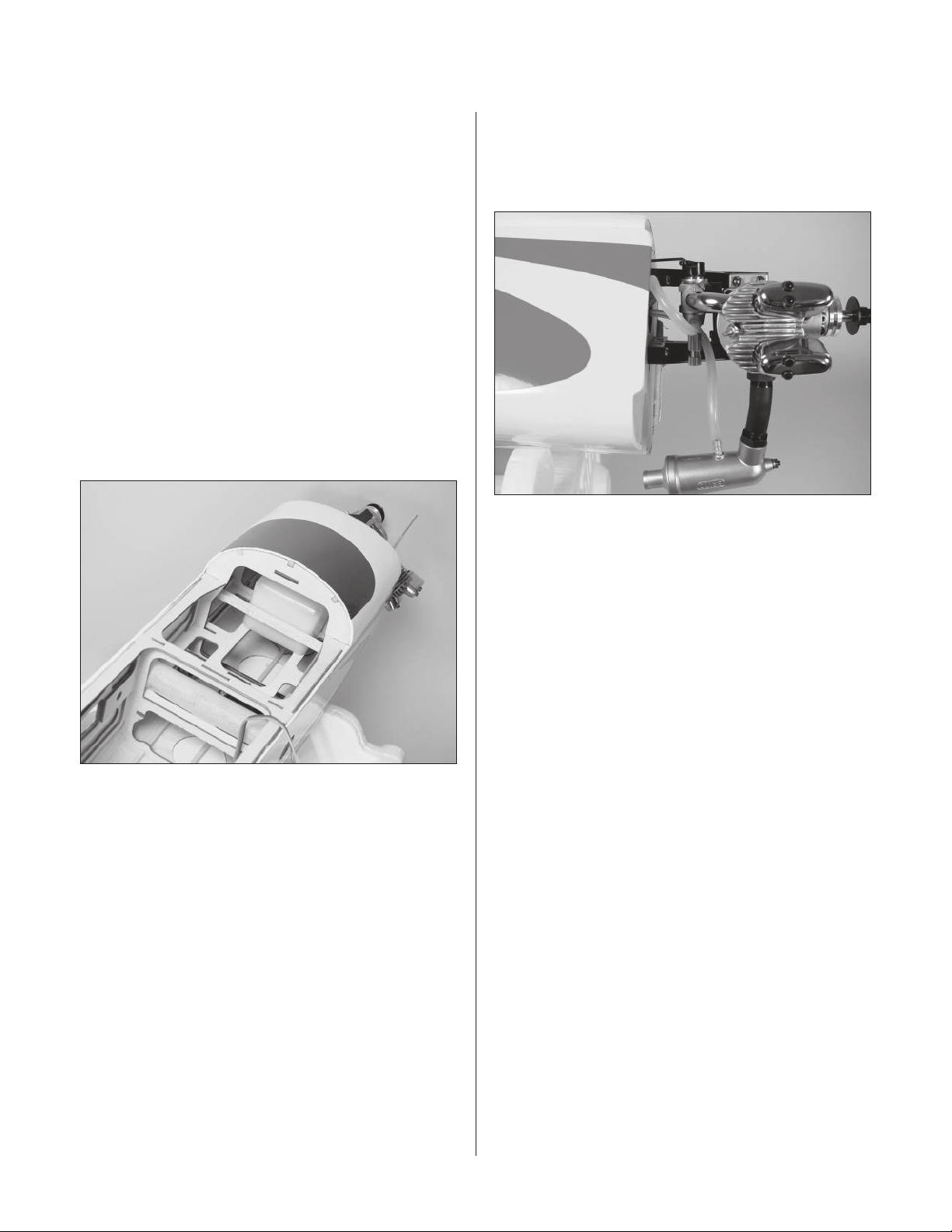
Step 11
Thread the clevis back onto pushrod. Attach the clevis to
the throttle arm. Move the throttle to full throttle using the
radio. Check the carburetor to make sure it is fully open.
Adjust the clevis to correspond full throttle on the radio to
full throttle on the carburetor. Use the radio to check low
for idle and closed. Move the linkage at the carburetor arm
and servo arm as necessary for full range of operation.
Step 12
Locate the fuel tank. Determine which fuel line is the vent
line by looking at the top of the fuel tank. Make a note as
to which side the vent line is located on. Slide the tank
into the fuselage, guiding the tubes out through the hole
in the firewall. Use the supplied stick to make a brace to
hold the tank in position.
Step 13
Attach the muffler to the engine. Make the proper
connections to the engine using the engine
manufacturer’s instructions.
27
Page 28
Section 6B: Two-Stroke Engine Installation
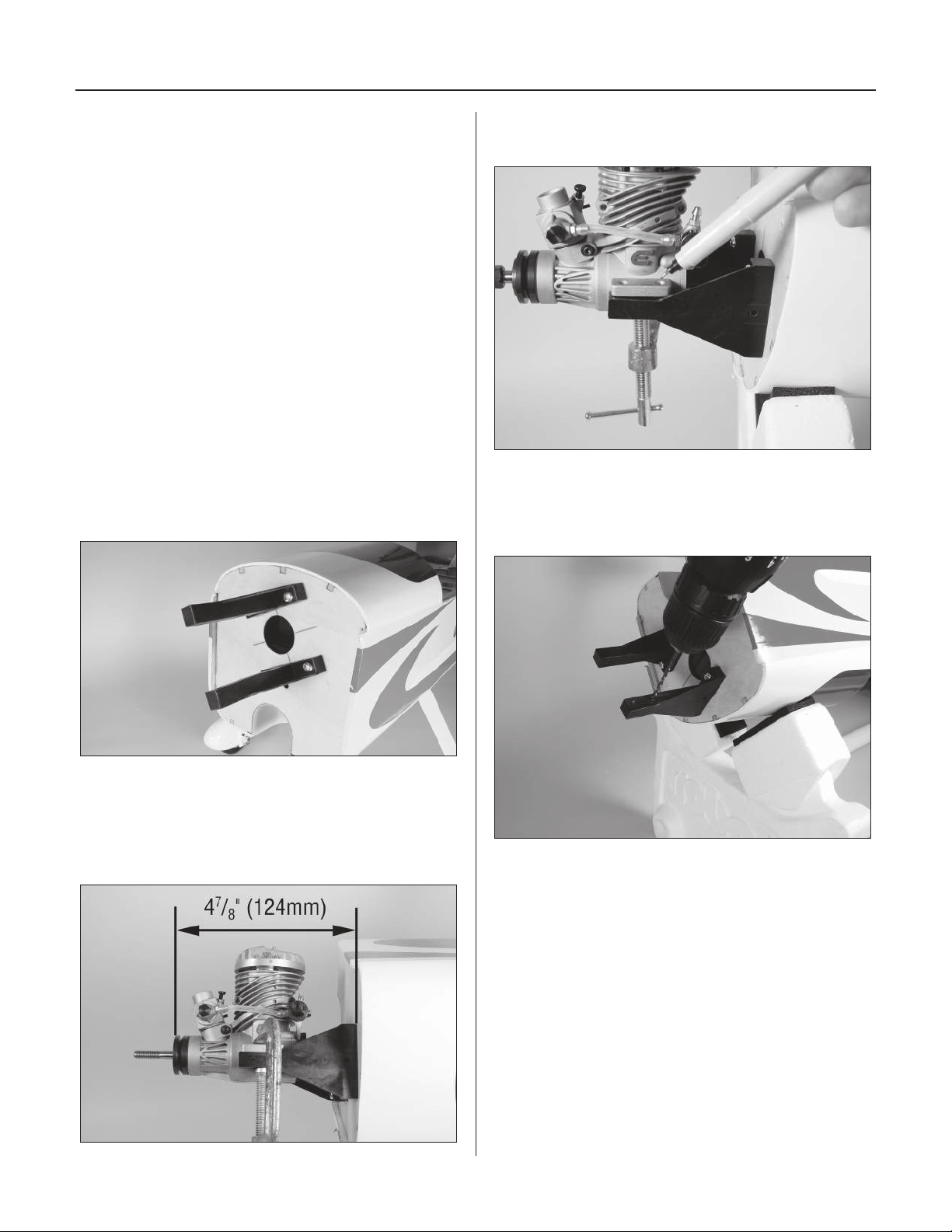
Required Parts
• Fuselage assembly • Engine mount (2)
• Clevis • Clevis retainer
•#8 x 5/8" self-tapping screw (4)
• 8-32 x 1" screw (4)
• 12" (305mm) outer pushrod tube
• 13" (330mm) pushrod wire
• Fuel tank assembly
Required Tools and Adhesives
• Drill • Clamp
• Phillips screwdriver (large) • Engine
• Medium CA • Sandpaper
• Drill bit: 5/32" (4mm), 7/64" (2.5mm)
Step 1
Attach the engine mount to the firewall using four
8-32 x 1" machine screws.
Step 3
Mark the locations for the engine mounting bolts.
Step 4
Remove the engine and drill the locations marked in the
previous step using an 7/64" (2.5mm) drill bit.
Step 2
Position the engine on the mount. Adjust the engine so
the distance from the firewall to the drive washer is 4
(124mm). Use clamps to hold the engine in position.
28
7
/8"
Hint: Use a drill press for the best
results. This makes holes perfectly
perpendicular (square) to the mount.
Page 29
Section 6B: Two-Stroke Engine Installation
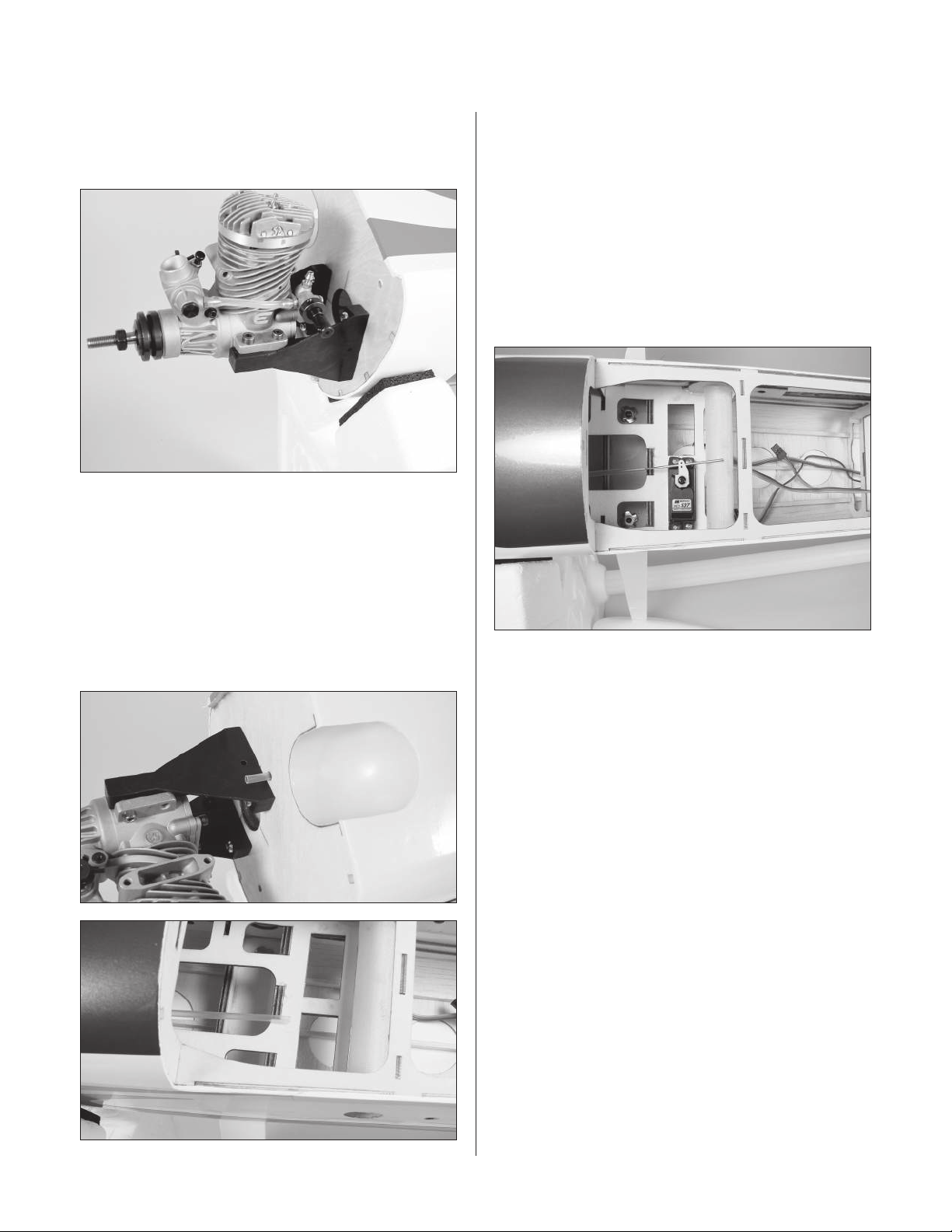
Step 5
Attach the engine using four #8 x 5/8" socket head
self-tapping screws.
Step 6
Test fit the 12" (305mm) outer pushrod tube through the
firewall and into the fuselage. Once satisfied with the fit,
roughen the tube using sandpaper. Slide the tube back
into position and use medium CA to glue it to the firewall.
Allow 1/4" (6mm) of the pushrod to extend forward of the
firewall. Trim the throttle pushrod at the front edge of the
throttle servo tray.
Step 7
Install the servo hardware (grommets and eyelets)
included with the servo. Mount the throttle servo with
the output shaft toward the pushrod tube. Slide a clevis
retainer onto a nylon clevis. Thread a clevis onto the
13" (330mm) pushrod wire a minimum of 10 turns.
Slide the pushrod into place from outside of the fuselage.
With the radio on and throttle servo plugged in, center
the throttle trim and stick. Use the screw from the servo
to secure the horn to the servo.
Note: Remove any extra arms from the servo
horn that may bind against the linkage.
29
Page 30
Section 6B: Two-Stroke Engine Installation
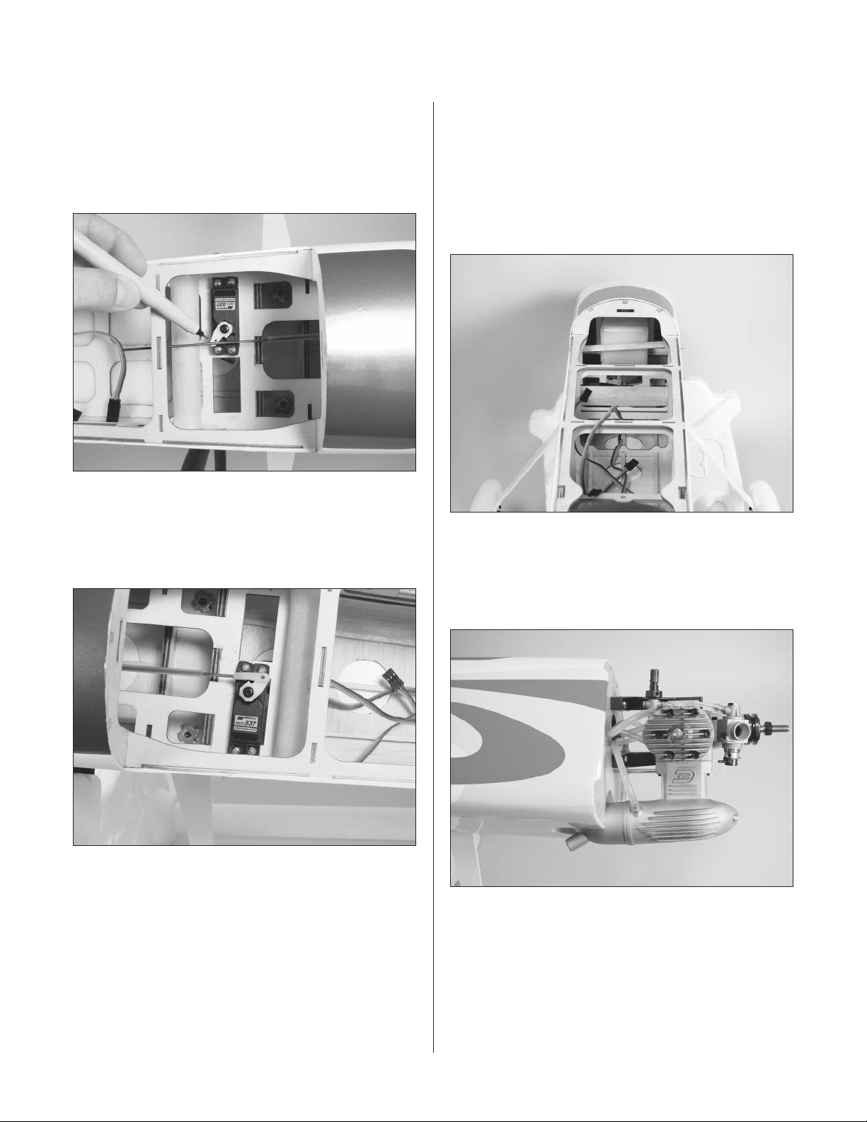
Step 8
Physically move the carburetor to the closed position. Use
the radio to move the throttle servo to the low position.
Mark the pushrod where it crosses the throttle servo arm
using a felt-tipped pen.
Step 9
Step 10
Locate the fuel tank. Determine which fuel line is the vent
line by looking at the top of the fuel tank. Make a note as
to which side the vent line is located on. Slide the tank
into the fuselage, guiding the tubes out through the hole
in the firewall. Use the supplied stick to make a brace to
hold the tank in position.
Bend the pushrod 90 degrees at the mark made in the last
step. Use a nylon pushrod keeper to secure the pushrod
wire to the servo arm.
Step 11
Attach the muffler to the engine. Make the proper
connections to the engine using the engine
manufacturer’s instructions.
30
Page 31
Section 7: Cowling Installation
Required Parts
• Fuselage assembly • Cowling
• #4 washer (4)
• 4-40 x 1/2" socket head screw (4)
Required Tools and Adhesives
• Hex wrench: 3/32" • Hobby scissors
• Hobby knife • Ruler
• Drill • Drill bit: 1/8" (3mm)
Step 1
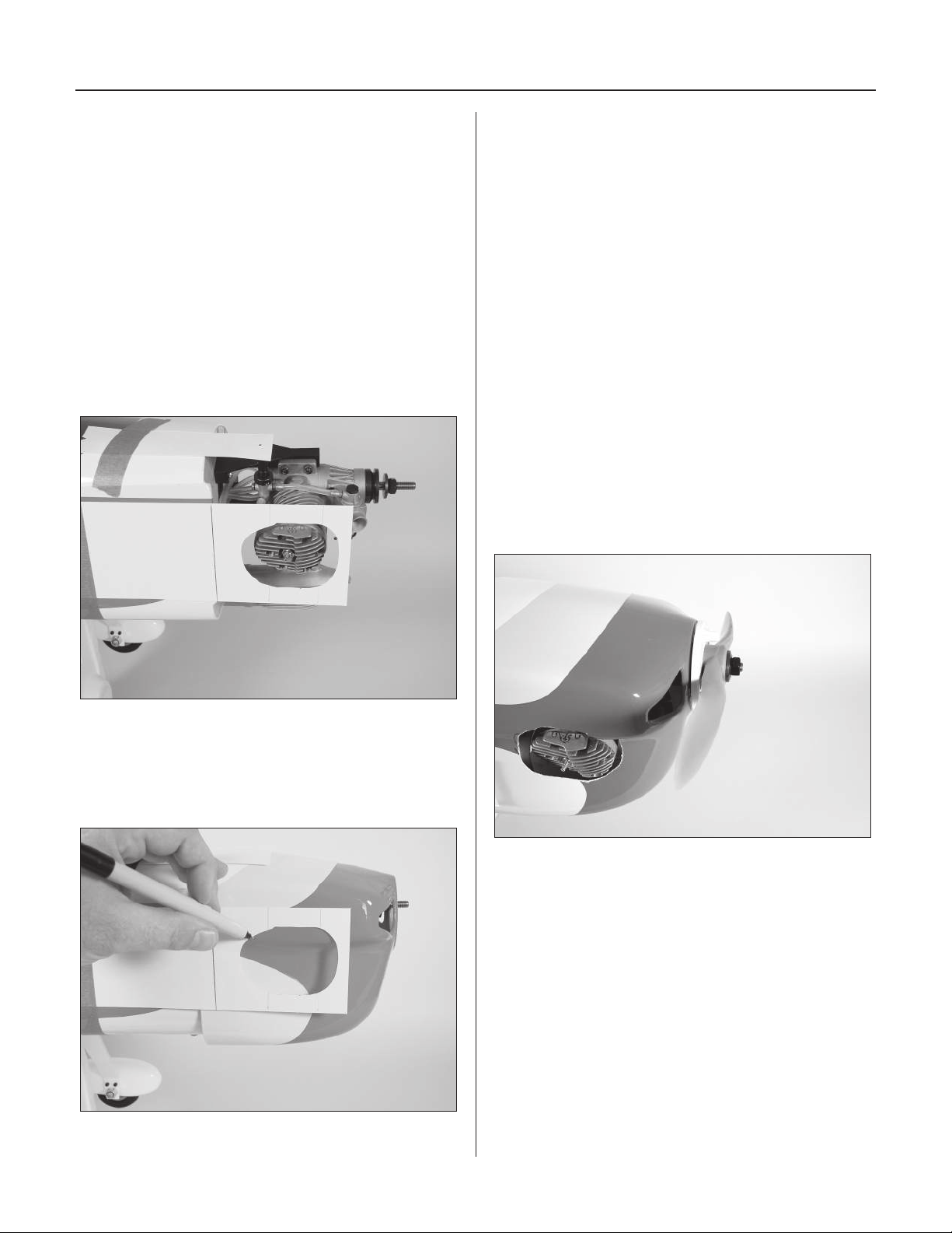
Use pieces of card stock to indicate the location of the
needle valve, engine head, and the firewall.
Step 3
Remove the cowl and remove the necessary material to fit
the cowl over the engine. Install the engine back onto the
firewall, and test fit the cowl over the engine.
Hint: Start by removing only a little material
at a time. You can always make the holes
bigger, but you can’t make them smaller. Work
until the cowl fits nicely over the engine.
Note: Remember to either trim material
from the cowl to attach the glow igniter,
or use a remove glow connection.
Step 4
Slide the cowling onto the fuselage. Temporarily
install the propeller and spinner backplate. Position
the cowl so there is 1/8" (3mm) gap between the
backplate and the cowl.
Step 2
Remove the engine. Position the cowl onto the fuselage
so it is roughly 5" (127mm) from the firewall. Transfer the
location for only the engine onto the cowl.
31
Page 32
Section 7: Cowling Installation
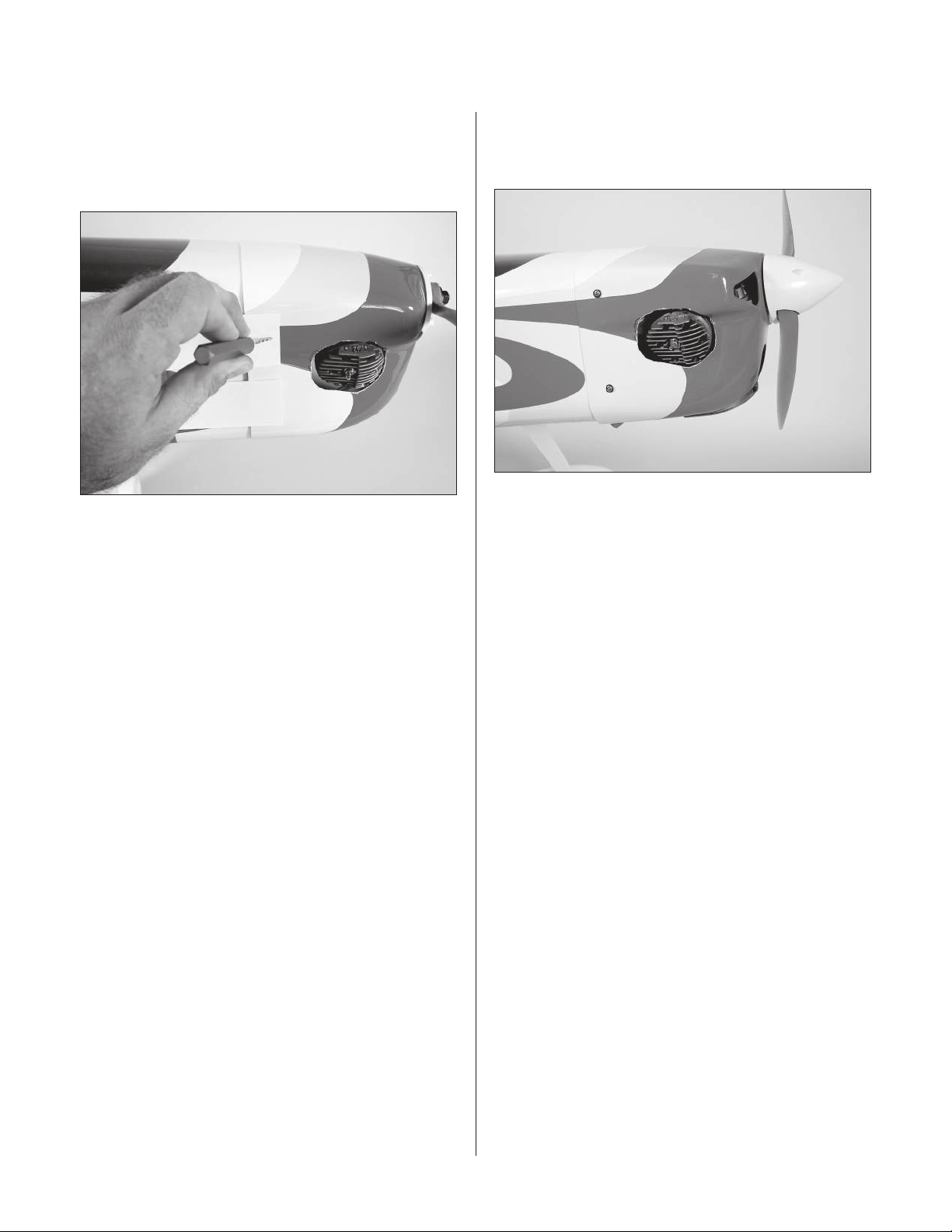
Step 5
Use the card stock from Step 1 to locate the positions
for the cowling screws. Drill the locations using a
1/8" (3mm) drill bit.
Step 6
Make any cutouts in the cowling to clear items such as the
muffler, fueling valve, needle valve, etc.
Step 7
Locate four #4 x 1/2" sheet metal screws. Attach the
cowling using the four screws.
32
Page 33
Section 8: Final Assembly
Required Parts
• Hatch • Canopy
• 4-40 x 1/2" screw (2) •#4 washer (3)
• Decals • Pilot figure
• Foam radio box • Radio hatch
• Side force generator (2)
Required Tools and Adhesives
• Hex wrench: 3/32" • Shoo Goo
• Formula 560-canopy glue • Masking tape
• Receiver • Receiver battery
• Switch harness
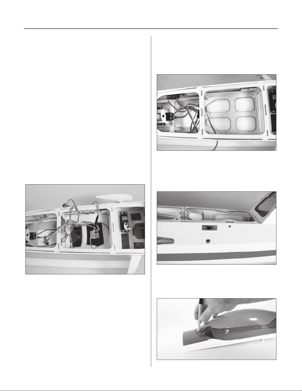
Step 1
Place a flat piece of foam into the fuselage, followed by
the shaped radio foam. Plug the servos and extensions
into their proper location in the receiver. Route the receiver
antenna wire through the tube on the right-hand side of
the fuselage to the tail. Place the receiver and receiver
battery into the foam.
Step 2
Place the remaining flat foam over the receiver and
receiver battery. Slide the radio plate into position
and secure it using a 4-40 X 1/2" socket head screw
and #4 washer.
Step 3
Remove the covering from the opening on the left side
of the fuselage for the switch harness. Install the harness
using the hardware provided with the harness.
Step 4
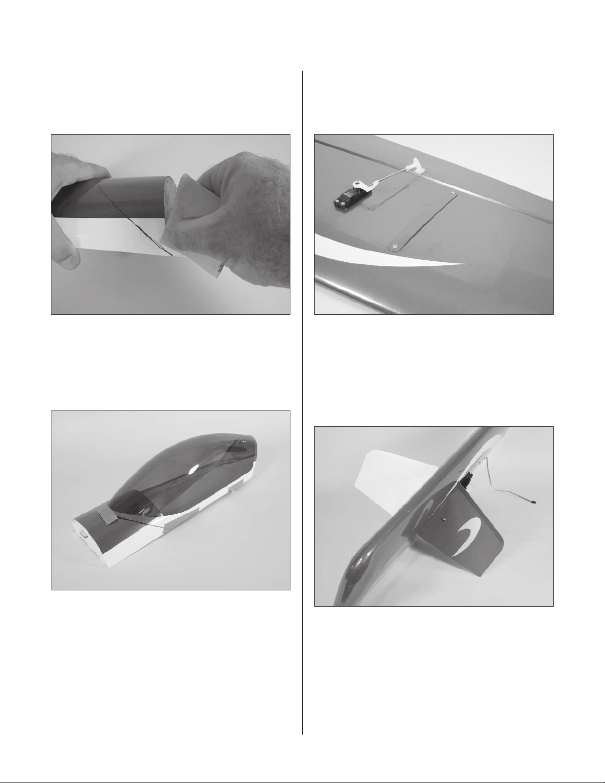
Position the canopy onto the canopy hatch. Trace around
the canopy and onto the hatch using a felt-tipped pen.
33
Page 34
Section 8: Final Assembly
Step 5
Lightly sand the inside edge of the canopy and
slightly inside the line drawn on the hatch using medium
sandpaper.
Step 6
Apply a bead of RCZ56 Canopy Glue (ZINJ5007) around
the inside edge of the canopy. Position the canopy onto
the hatch. Use tape to hold the canopy secure until the
glue fully cures.
Step 7
If you are not planning on using the side force generators,
secure the side force generator plugs to the wing using
#2 x 1/4" screws.
Step 8
To install the side force generators, first remove the
plugs. Slide the side force generators partially into
the slot in the wing. When the stud is visible, install
the thumbscrew to pull the upper and lower side force
generators into position.
34
Note: The SFG’s can be removed in
a few seconds. Try your ShowTime
50 with and without to decide which
setup suits your flying style best.
™
Step 9
Apply the decals to customize your ShowTime 50.
Page 35
Center of Gravity
An important part of preparing the aircraft for flight is
properly balancing the model. This is especially important
when various engines are mounted.
Caution: Do not inadvertently skip this step!
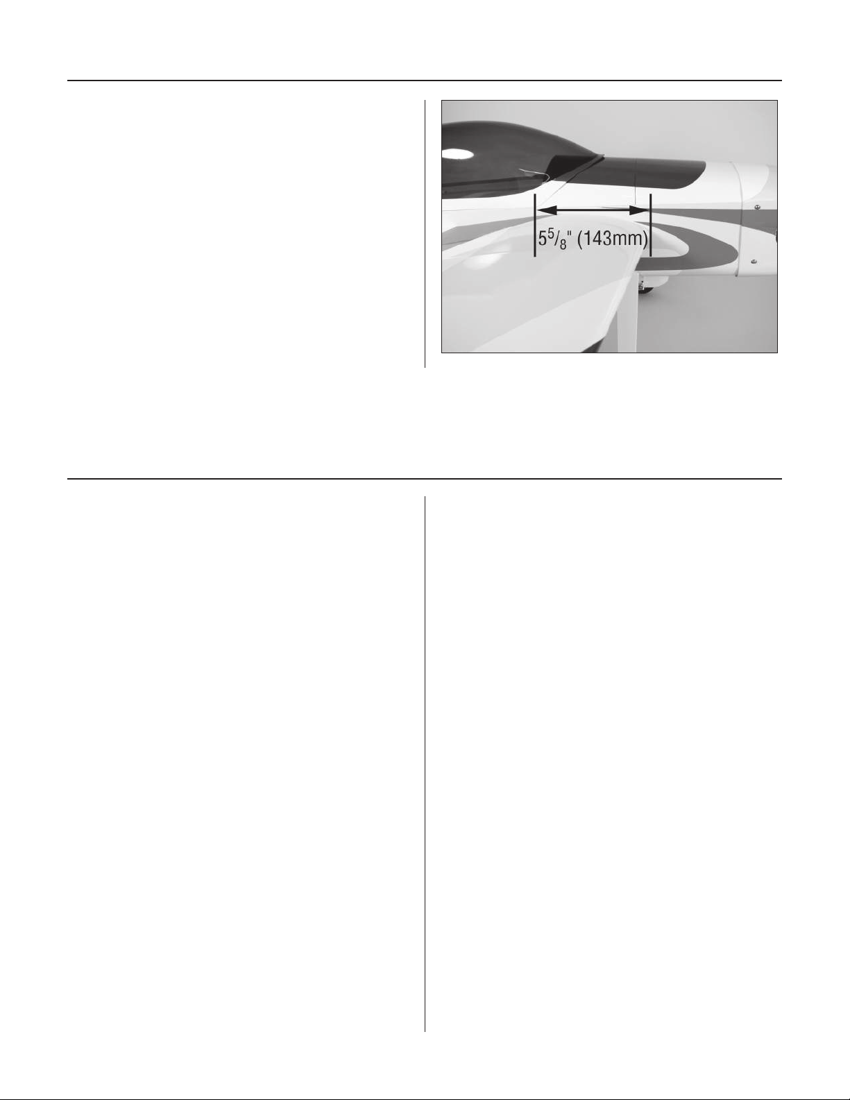
The recommended Center of Gravity (CG) location for
the ShowTime
edge of the wing against the fuselage (at the root rib). If
necessary, move the battery pack or add weight to either
the nose or the tail until the correct balance is achieved.
Stick-on weights are available at your local hobby store
and work well for this purpose.
™
50 is 5 5/8" (143mm) behind the leading
Radio Setup
A 7-channel or greater computer radio is highly
recommended. This allows the following features:
• Mixing the right aileron to the left aileron (flaperon mix)
• Electronically adjustable aileron differential
• Mixing the right elevator to the left elevator (dual
elevator mixing)
• Independent travel and trim adjustments for each
elevator half
When using a 7-channel or greater computer radio,
each servo is plugged into its own separate channel.
Consult your radio manual for specific details on
hookup and programming.
If using a 6-channel radio with flaperon mix, the aileron
servos are each plugged into their own channels. The
right aileron plugs into the aileron socket in the receiver,
while the left aileron plugs into channel 6. With flaperon
activated in the programming, this allows for independent
travel adjustment of each aileron in each direction and
electronic aileron differential. Consult your manual for
more programming details.
With a 6-channel computer radio, it will be necessary to
Y-harness the two elevator servos; a reversed elevator
servo is needed to achieve the correct control direction.
A servo reverser can be used here.
Using a non-computer radio will require that the aileron
and elevator be Y-harnessed. Be sure to use a reversed
servo (or a reverser) for one of the elevator servos. If
you’ve ever thought about purchasing a computer radio,
now is a good time to do it.
35
Page 36
Control Throws
Setting the control throws for your ShowTime™ 50
does require some attention to detail. To correctly set
the throws, it is highly suggested to use the following
procedure to achieve the greatest mechanical advantage
from your servos.
Step 1
Determine the maximum amount of control surface throw
from the throws listed. Use this 3D throws to set the
maximum amount of throw, then use your computer radio
for the lower rate listed.
Step 2
Set the Travel Adjust (ATV on Futaba transmitter) to about
15% under the max. (On a JR
®
transmitter that is 135%.)
Make sure to set both directions during this process.
Step 3
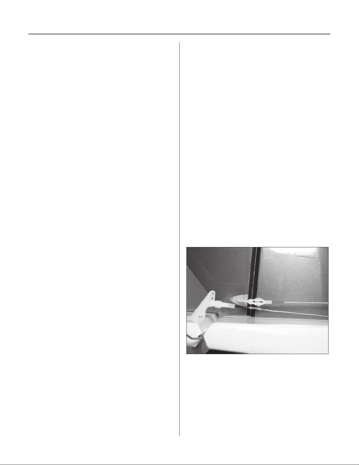
Adjust the position of the clevis on the control horn and
position of the ball link on the servo arm to achieve the
throw decided in Step 1. It is highly recommended not to
change the position on the servo arm unless absolutely
necessary. Use Travel Adjust (ATV) to finalize the throws.
That is why we left a little margin in the percentages back
in Step 2.
There isn’t an exact geometry to the linkage, as it depends
on how much throw each individual modeler requires.
The linkage geometry should always be maximized so the
servo isn’t working any harder than it has to.
Elevator Up Down
Low rate 9° (9/16") 10.5° (5/8")
High rate 43° (2
5
/8") 43° (2 5/8")
Aileron Up Down
Low rate 13° (1
High rate 37° (3") 35.5° (2
1
/16") 12° (1")
15
/16")
(Measured at the inboard end for linear measurements)
Rudder Left/Right
Low rate 28 deg (2
High rate 45 deg (3
1
3
/2")
/4")
(Measured at top for linear measurements)
Once the control throws have been set, use the supplied
heat shrink tubing on each clevis to prevent them from
opening during flight.
Step 4
If setting a dual elevator or aileron, match the linkage
locations used back in Step 3. Increase or decrease the
Travel Adjust (ATV) a few points as necessary to fine-tune
the throws to match up left and right sides and up and
down throws so all is symmetrical.
This is all necessary to tune the mechanical advantage
as good as possible. When setting up a model for 3D,
the mechanical advantage will be less because of the
large throws, and thus the servo will work harder and
wear faster. Using an insufficient servo for the job, or
trying to get too much throw, will cause something to
fail, probably the servo.
36
Page 37

Rates and Expos
Use Expo to soften the feel of the model. On high 3D
rates use quite a bit of expo. The goal on 3D rates is to
get the model to feel the same around neutral as it does
on low rates.
Use low rate settings for all flying except for 3D
aerobatics. For precision flying or general sport hotdogging, the low rate throws are perfect, even for snap
rolls. The only exception is rudder rates. Use 3D rudder
rate when doing stall turns and rolling circles, since
the more rudder the better for these. When doing 3D
aerobatics, flip to 3D rates just before the maneuver. As
soon as the maneuver is done, flip back down to low rate
to avoid over-controlling the model.
Range Test Your Radio
Step 1
Before each flying session, be sure to range check your
radio. This is accomplished by turning on your transmitter
with the antenna collapsed. Turn on the receiver in your
airplane. With your airplane on the ground and the
engine running, you should be able to walk 30 paces
(approximately 100 feet) away from your airplane and still
have complete control of all functions.
If not, don’t attempt to fly! Have your radio
equipment checked out by the manufacturer.
Step 2
Double-check that all controls (aileron, elevator, rudder
and throttle) move in the correct direction.
Step 3
Be sure that your batteries are fully charged, per the
instructions included with your radio.
37
Page 38

2006 Official AMA
National Model Aircraft Safety Code
GENERAL
1) I will not fly my model aircraft in sanctioned
events, air shows or model flying demonstrations until
it has been proven to be airworthy by having been
previously, successfully flight tested.
2) I will not fly my model higher than approximately
400 feet within 3 miles of an airport without notifying
the airport operator. I will give right-of-way and avoid
flying in the proximity of full-scale aircraft. Where
necessary, an observer shall be utilized to supervise
flying to avoid having models fly in the proximity of
full-scale aircraft.
3) Where established, I will abide by the safety rules
for the flying site I use, and I will not willfully and
deliberately fly my models in a careless, reckless and/
or dangerous manner.
4) The maximum takeoff weight of a model is 55
pounds, except models flown under Experimental
Aircraft rules.
5) I will not fly my model unless it is identified with
my name and address or AMA number, on or in the
model. (This does not apply to models while being
flown indoors.)
6) I will not operate models with metal-bladed
propellers or with gaseous boosts, in which gases
other than air enter their internal combustion
engine(s); nor will I operate models with extremely
hazardous fuels such as those containing
tetranitromethane or hydrazine.
7) I will not operate models with pyrotechnics (any
device that explodes, burns, or propels a projectile
of any kind) including, but not limited to, rockets,
explosive bombs dropped from models, smoke
bombs, all explosive gases (such as hydrogen-filled
balloons), or ground mounted devices launching a
projectile. The only exceptions permitted are rockets
flown in accordance with the National Model Rocketry
Safety Code or those permanently attached (as per
JATO use); also those items authorized for Air Show
Team use as defined by AST Advisory Committee
(document available from AMA HQ). In any case,
models using rocket motors as a primary means of
propulsion are limited to a maximum weight of 3.3
pounds and a G series motor. (A model aircraft is
defined as an aircraft with or without engine, not able
to carry a human being.)
8) I will not consume alcoholic beverages prior to,
nor during, participation in any model operations.
9) Children under 6 years old are only allowed
on the flight line as a pilot or while receiving
flight instruction.
RADIO CONTROL
1) I will have completed a successful radio equipment
ground range check before the first flight of a new or
repaired model.
2) I will not fly my model aircraft in the presence
of spectators until I become a qualified flier, unless
assisted by an experienced helper.
3) At all flying sites a straight or curved line(s) must
be established in front of which all flying takes place
with the other side for spectators. Only personnel
involved with flying the aircraft are allowed at or in
the front of the flight line. Intentional flying behind the
flight line is prohibited.
4) I will operate my model using only radio control
frequencies currently allowed by the Federal
Communications Commission. (Only properly
licensed Amateurs are authorized to operate
equipment on Amateur Band frequencies.)
38
Page 39

2006 Official AMA
National Model Aircraft Safety Code
5) Flying sites separated by three miles or more
are considered safe from site-to site interference,
even when both sites use the same frequencies. Any
circumstances under three miles separation require
a frequency management arrangement, which may
be either an allocation of specific frequencies for
each site or testing to determine that freedom from
interference exists. Allocation plans or interference
test reports shall be signed by the parties involved
and provided to AMA Headquarters. Documents of
agreement and reports may exist between (1) two
or more AMA Chartered Clubs, (2) AMA clubs and
individual AMA members not associated with AMA
Clubs, or (3) two or more individual AMA members.
6) For Combat, distance between combat engagement
line and spectator line will be 500 feet per cubic
inch of engine displacement. (Example: .40 engine
= 200 feet.); electric motors will be based on
equivalent combustion engine size. Additional safety
requirements will be per the RC Combat section of the
current Competition Regulations.
7) At air shows or model flying demonstrations, a
single straight line must be established, one side of
which is for flying, with the other side for spectators.
8) With the exception of events flown under AMA
Competition rules, after launch, except for pilots or
helpers being used, no powered model may be flown
closer than 25 feet to any person.
9) Under no circumstances may a pilot or other
person touch a powered model in flight.
Organized RC Racing Event
10) An RC racing event, whether or not an AMA Rule
Book event, is one in which model aircraft compete
in flight over a prescribed course with the objective of
finishing the course faster to determine the winner.
A. In every organized racing event in which
contestants, callers and officials are on the course:
1. All officials, callers and contestants must properly
wear helmets, which are OSHA, DOT, ANSI, SNELL or
NOCSAE approved or comparable standard while on
the racecourse.
2. All officials will be off the course except for the
starter and their assistant.
3.”On the course” is defined to mean any area beyond
the pilot/staging area where actual flying takes place.
B. I will not fly my model aircraft in any organized
racing event which does not comply with paragraph A
above or which allows models over 20 pounds unless
that competition event is AMA sanctioned.
C. Distance from the pylon to the nearest spectator
(line) will be in accordance with the current
Competition Regulations under the RC Pylon Racing
section for the specific event pending two or three
pylon course layout.
11) RC night flying is limited to low-performance
models (less than 100 mph). The models must be
equipped with a lighting system that clearly defines
the aircraft’s position in the air at all times.
39
Page 40

9381
5.
© 2006 Horizon Hobby, Inc.
4105 Fieldstone Road
Champaign, Illinois 61822
(877) 504-0233
horizonhobby.com
 Loading...