

Page 1
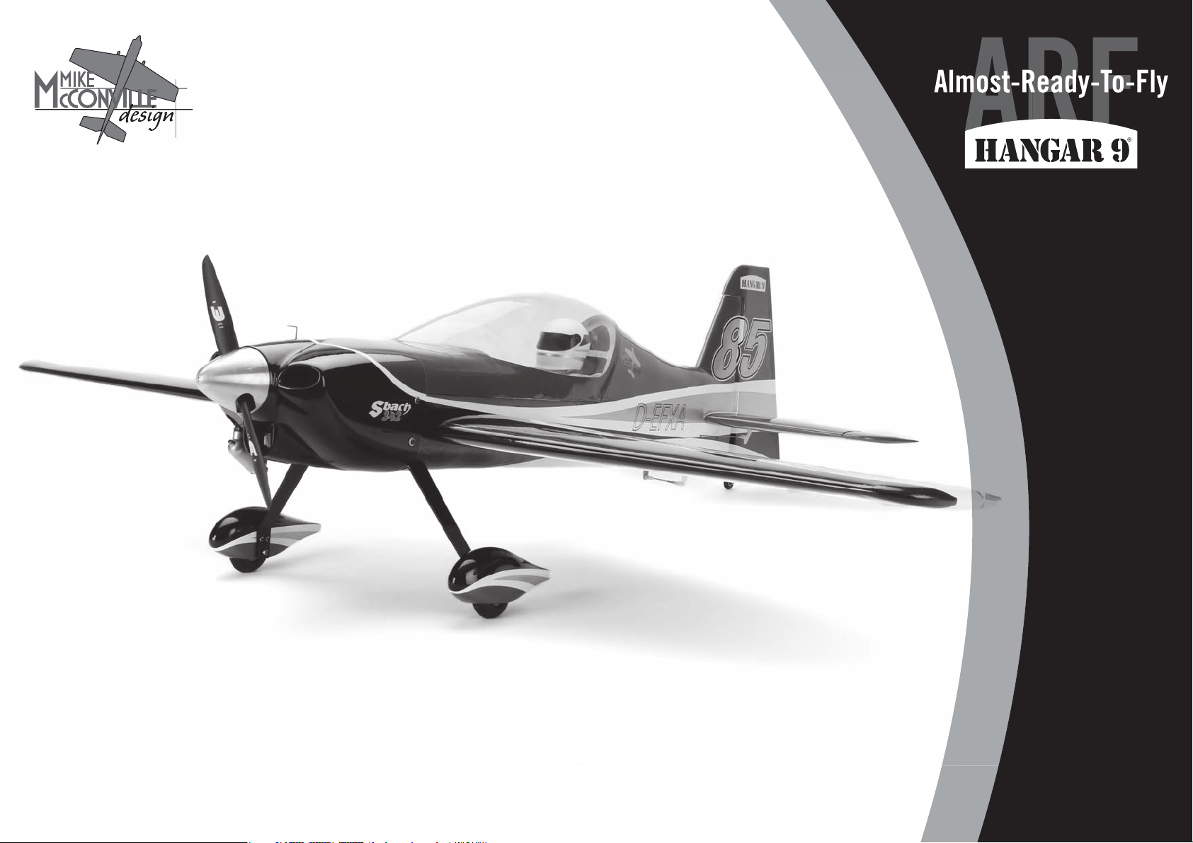
Sbach® 342 60
Instruction Manual
Bedienungsanleitung
Manuel d’utilisation
Manuale di Istruzioni
1
Page 2

NOTICE
All instructions, warranties and other collateral documents are subject to change at the sole discretion of Horizon Hobby,
Inc. For up-to-date product literature, visit horizonhobby. com and click on the support tab for this product.
Meaning of Special Language
The following terms are used throughout the product literature to indicate various levels of potential harm when operating
this product:
NOTICE: Procedures, which if not properly followed, create a possibility of physical property damage AND a little or no
possibility of injury.
CAUTION: Procedures, which if not properly followed, create the probability of physical property damage AND a
possibility of serious injury.
WARNING: Procedures, which if not properly followed, create the probability of property damage, collateral damage,
and serious injury OR create a high probability of superfi cial injury.
WARNING: Read the ENTIRE instruction manual to become familiar with the features of the product before
operating. Failure to operate the product correctly can result in damage to the product, personal property and cause
serious injury.
This is a sophisticated hobby product. It must be operated with caution and common sense and requires some basic
mechanical ability. Failure to operate this Product in a safe and responsible manner could result in injury or damage to the
product or other property. This product is not intended for use by children without direct adult supervision. Do not use with
incompatible components or alter this product in any way outside of the instructions provided by Horizon Hobby, Inc. This
manual contains instructions for safety, operation and maintenance. It is essential to read and follow all the instructions
and warnings in the manual, prior to assembly, setup or use, in order to operate correctly and avoid damage or serious
injury.
SAFETY WARNINGS AND PRECAUTIONS
Read and follow all instructions and safety precautions
before use. Improper use can result in fi re, serious injury and
damage to property.
Components
Use only with compatible components. Should any
compatibility questions exist, please refer to the product
instructions, component instructions or contact the
appropriate Horizon Hobby offi ce.
Flight
Fly only in open areas to ensure safety. It is recommended
fl ying be done at radio control fl ying fi elds. Consult local
ordinances before choosing a fl ying location.
Propeller
Keep loose items that can become entangled in the propeller
away from the prop. This includes loose clothing or other
objects such as pencils and screwdrivers. Keep your hands
away from the propeller as injury can occur.
Batteries
Always follow the manufacturer’s instructions when using
and disposing of any batteries. Mishandling of Li-Po
batteries can result in fi re causing serious injury and
damage.
Small Parts
This kit includes small parts and should not be left
unattended near children as choking and serious injury could
result.
SAFE OPERATING RECOMMENDATIONS
• Inspect your model before every fl ight to ensure it is
airworthy.
• Be aware of any other radio frequency user who may
present an interference problem.
• Always be courteous and respectful of other users in your
selected fl ight area.
• Choose an area clear of obstacles and large enough to
safely accomodate your fl ying activity.
• Make sure this area is clear of friends and spectators
prior to launching your aircraft.
• Be aware of other activities in the vicinity of your fl ight
path that could cause potential confl ict.
• Carefully plan your fl ight path prior to launch.
• Abide by any and all established AMA National Model
Aircraft Safety Code.
Age Recommendation: Not for children under 14 years. This is not a toy.
USING THE MANUAL
This manual is divided into sections to help make assembly easier to understand. Boxes () have been placed next to
each step. These help keep track of steps that have been completed.
2
Page 3

HINWEIS
Alle Anweisungen, Garantien und anderen zugehörigen Dokumente können im eigenen Ermessen von Horizon Hobby, Inc.
jederzeit geändert werden. Die aktuelle Produktliteratur fi nden Sie auf horizonhobby.com unter der Registerkarte „Support“
für das betreffende Produkt.
Spezielle Bedeutungen
Die folgenden Begriffe werden in der gesamten Produktliteratur verwendet, um auf unterschiedlich hohe Gefahrenrisiken
beim Betrieb dieses Produkts hinzuweisen:
HINWEIS: Wenn diese Verfahren nicht korrekt befolgt werden, können sich möglicherweise Sachschäden UND geringe
oder keine Gefahr von Verletzungen ergeben.
ACHTUNG: Wenn diese Verfahren nicht korrekt befolgt werden, ergeben sich wahrscheinlich Sachschäden UND die
Gefahr von schweren Verletzungen.
WARNUNG: Wenn diese Verfahren nicht korrekt befolgt werden, ergeben sich wahrscheinlich Sachschäden,
Kollateralschäden und schwere Verletzungen ODER mit hoher Wahrscheinlichkeit oberfl ächliche Verletzungen.
WARNUNG: Lesen Sie die GESAMTE Bedienungsanleitung, um sich vor dem Betrieb mit den Produktfunktionen
vertraut zu machen. Wird das Produkt nicht korrekt betrieben, kann dies zu Schäden am Produkt oder persönlichem
Eigentum führen oder schwere Verletzungen verursachen.
WARNUNGEN UND SICHERHEITSVORKEHRUNGEN
Bitte lesen und befolgen Sie alle Anweisungen und
Sichervorkehrungen vor dem Gebrauch. Falscher, nicht
sachgemäßer Gebrauch kann Feuer, ernsthafte Verletzungen
und Sachbeschädigungen zur Folge haben.
Komponenten
Verwenden Sie mit dem Produkt nur kompatible
Komponenten. Sollten Fragen zur Kompatibilität auftreten,
lesen Sie bitte die Produkt- oder Bedienungsanweisung oder
kontaktieren den Service von Horizon Hobby.
Fliegen
Fliegen Sie um Sicherheit garantieren zu können, nur in
weiten offenen Gegenden. Wir empfehlen hier den Betrieb auf
zugelassenen Modellfl ugplätzen. Bitte beachten Sie lokale
Vorschriften und Gesetze, bevor Sie einen Platz zum Fliegen
wählen.
Propeller
Halten Sie lose Gegenstände die sich im Propeller
verfangen können weg vom Propeller. Dieses gilt auch für
Kleidung oder andere Objekte wie zum Beispiel Stifte oder
Schraubendreher.
EMPFEHLUNGEN ZUM SICHEREN
BETRIEB
• Überprüfen Sie zur Flugtauglichkeit ihr Modell vor jedem
Flug.
• Beachten Sie andere Piloten deren Sendefrequenzen ihre
Frequenz stören könnte.
• Begegnen Sie anderen Piloten in ihrem Fluggebiet immer
höfl ich und respektvoll.
• Wählen Sie ein Fluggebiet, dass frei von Hindernissen und
groß genug ist.
• Stellen Sie vor dem Start sicher, dass die Fläche frei von
Freunden und Zuschauern ist.
• Beobachten Sie den Luftraum und andere Flugzeuge/
Objekte die ihren Flugweg kreuzen und zu einem Konfl ikt
führen könnten.
• Planen Sie sorgfältig ihren Flugweg vor dem Start.
Dies ist ein hochentwickeltes Hobby-Produkt. Es muss mit Vorsicht und gesundem Menschenverstand betrieben werden
und benötigt gewisse mechanische Grundfähigkeiten. Wird dieses Produkt nicht auf eine sichere und verantwortungsvolle
Weise betrieben, kann dies zu Verletzungen oder Schäden am Produkt oder anderen Sachwerten führen. Dieses Produkt
eignet sich nicht für die Verwendung durch Kinder ohne direkte Überwachung eines Erwachsenen. Verwenden Sie das
Produkt nicht mit inkompatiblen Komponenten oder verändern es in jedweder Art ausserhalb der von Horizon Hobby, Inc.
vorgegebenen Anweisungen. Diese Bedienungsanleitung enthält Anweisungen für Sicherheit, Betrieb und Wartung. Es ist
unbedingt notwendig, vor Zusammenbau, Einrichtung oder Verwendung alle Anweisungen und Warnhinweise im Handbuch
zu lesen und zu befolgen, damit es bestimmungsgemäß betrieben werden kann und Schäden oder schwere Verletzungen
vermieden werden.
Nicht geeignet für Kinder unter 14 Jahren. Dies ist kein Spielzeug.
ÜBER DIESE ANLEITUNG
Diese Anleitung ist zur Vereinfachung des Zusammenbaues in Sektionen unterteilt. Neben den Sektionen befi nden sich
Kästchen () die es Ihnen leichter machen den Arbeitsschritt als erledigt abzuhaken.
Halten Sie ihre Hände weg vom Propeller, es besteht akute
Verletzungsgefahr.
Akkus
Folgen Sie immer den Herstelleranweisungen bei dem
Gebrauch oder Entsorgung von Akkus. Falsche Behandlung
von LiPo Akkus kann zu Feuer mit Körperverletzungen und
Sachbeschädigung führen.
Kleinteile
Dieser Baukasten beinhaltet Kleinteile und darf nicht
unbeobachtet in der Nähe von Kindern gelassen werden,
da die Teile verschluckt werden könnten mit ernsthaften
Verletzung zur Folge.
3
Page 4

REMARQUE
La totalité des instructions, garanties et autres documents est sujette à modifi cation à la seule discrétion d’Horizon Hobby,
Inc. Pour obtenir la documentation àjour, rendez-vous sur le site horizonhobby.com et cliquez sur l’onglet de support de ce
produit.
AVERTISSEMENTS RELATIFS À LA
SÉCURITÉ
Lisez et suivez toutes les instructions relatives à la sécurité
avant utilisation. Une utilisation inappropriée peut entraîner
un incendie, de graves blessures et des dégâts matériels.
CONSIGNES DE SÉCURITÉ CONCERNANT
L’UTILISATION
• Inspectez votre modèle avant chaque vol.
• Surveillez les fréquences utilisées à proximité.
Signifi cation de certains termes spécifi ques
Les termes suivants sont utilisés dans l’ensemble du manuel pour indiquer différents niveaux de danger lors de
l’utilisation de ce produit:
REMARQUE: Procédures qui, si elles ne sont pas suivies correctement, peuvent entraîner des dégâts matériels ET
éventuellement un faible risque de blessures.
ATTENTION: Procédures qui, si elles ne sont pas suivies correctement, peuvent entraîner des dégâts matériels ET des
blessures graves.
AVERTISSEMENT: Procédures qui, si elles ne sont pas suivies correctement, peuvent entraîner des dégâts
matériels et des blessures graves OU engendrer une probabilité élevée de blessure superfi cielle.
AVERTISSEMENT: Lisez la TOTALITÉ du manuel d’utilisation afi n de vous familiariser avec les
caractéristiques du produit avant de le faire fonctionner. Une utilisation incorrecte du produit peut entraîner sa
détérioration, ainsi que des risques de dégâts matériels, voire de blessures graves.
Ceci est un produit de loisirs sophistiqué. Il doit être manipulé avec prudence et bon sens et requiert des aptitudes
de base en mécanique. Toute utilisation irresponsable de ce produit ne respectant pas les principes de sécurité peut
provoquer des blessures, entraîner des dégâts matériels et endommager le produit. Ce produit n’est pas destiné à être
utilisé par des enfants sans la surveillance directe d’un adulte. N’essayez pas de modifi er ou d’utiliser ce produit avec des
composants incompatibles hors des instructions fournies par Horizon Hobby, Inc. Ce manuel comporte des instructions
relatives à la sécurité, au fonctionnement et à l’entretien. Il est capital de lire et de respecter la totalité des instructions et
avertissements du manuel avant l’assemblage, le réglage et l’utilisation, ceci afi n de manipuler correctement l’appareil et
d’éviter tout dégât matériel ou toute blessure grave.
Composants
Utilisez uniquement des composants compatibles. Si vous
avez des questions concernant la compatibilité, référez-vous
à ce manuel ou contactez le service technique Horizon Hobby.
Le vol
Volez uniquement dans des zones dégagées pour un
maximum de sécurité. Il est recommandé d’utiliser les pistes
des clubs d’aéromodélisme. Consultez votre mairie pour
connaître les sites autorisés.
L’hélice
Gardez éloignés tous les éléments qui pourraient être
attrapés par l’hélice. Cela inclut les vêtements larges ou les
objets comme des outils par exemple. Gardez toujours vos
mains à distance pour éviter tout cas de blessures.
Les batteries
Suivez toujours les instructions du fabricant de vos
batteries. Une mauvaise manipulation d’une batterie
Li-Po peut entraîner un incendie causant de graves dégâts
matériels et des blessures corporelles.
Petites pièces
Ce kit contient des petites pièces qui ne doivent pas
être laissées à la portée des enfants, ces pièces sont
dangereuses pour eux et peuvent entraîner de graves
blessures.
• Soyez toujours courtois et respectueux des autres
utilisateurs de la zone de vol.
• Choisissez une zone dégagée de tout obstacle et
suffi samment grande pour voler en toute sécurité.
• Contrôlez que la zone est libre de spectateurs avant de
lancer votre modèle.
• Soyez conscient des autres activités aux alentours de
votre vol, pour éviter tout confl it potentiel.
• Planifi ez votre vol avant de le commencer.
14 ans et plus. Ceci n’est pas un jouet.
UTILISATION DU MANUEL
Ce manuel est divisé en sections pour vous aider à comprendre plus facilement l’assemblage. Des cases () ont été
placées à chaque étape. Cela vous permet d’avoir un suivi des étapes déjà effectuées.
4
Page 5

AVVISO
Tutte le istruzioni, le garanzie e gli altri documenti pertinenti sono soggetti a cambiamenti a totale discrezione di Horizon
Hobby, Inc. Per una documentazione aggiornata sul prodotto, visitare il sito www.horizonhobby.com e fare clic sulla sezione
Support per questo prodotto.
Signifi cato dei termini particolari
In tutta la documentazione relativa al prodotto sono utilizzati iseguenti termini per indicare vari livelli di potenziale
pericolo durante il funzionamento:
AVVISO: Procedure che, se non sono seguite correttamente, possono creare danni materiali E nessuna oscarsa
possibilità di lesioni.
ATTENZIONE: Procedure che, se non sono seguite correttamente, possono creare danni materiali E possibili gravi
lesioni.
AVVERTENZA: Procedure che, se non debitamente seguite, espongono alla possibilità di danni alla proprietà
fi sica opossono omportare un’elevata possibilità di provocare ferite superfi ciali. Ulteriori precauzioni per la sicurezza e
avvertenze.
AVVERTIMENTI E PRECAUZIONI PER LA
SICUREZZA
Prima dell’uso leggere attentamente tutte le istruzioni e le
precauzioni per la sicurezza. In caso contrario si potrebbero
procurare incendi, danni o ferite.
Componenti
Usare solo componenti compatibili. Se ci fossero dubbi
riguardo alla compatibilità, è opportuno far riferimento
alle istruzioni relative al prodotto o ai componenti oppure
rivolgersi al reparto Horizon Hobby di competenza.
Volo
Per sicurezza volare solo in aree molto ampie. Meglio se si
va su campi volo autorizzati per modellismo. Consultare le
ordinanze locali prima di scegliere una ubicazione.
Elica
RACCOMANDAZIONI PER OPERARE IN
SICUREZZA
• Controllare attentamente il modello prima di ogni volo per
accertarsi che sia idoneo.
• Essere consapevoli che un altro utente della frequenza in
uso, potrebbe procurare delle interferenze.
• Essere sempre cortesi e rispettosi nei confronti degli altri
utilizzatori dell’area in cui ci si trova.
• Scegliere un’area libera da ostacoli e abbastanza ampia
da permettere lo svolgimento del volo in sicurezza.
• Prima del volo verifi care che l’area sia libera da amici e
spettatori.
• Stare attenti alle altre attività che si svolgono in
vicinanza della vostra traiettoria di volo, per evitare
possibili confl itti.
AVVERTENZA: Leggere TUTTO il manuale di istruzioni e prendere familiarità con le caratteristiche del
prodotto, prima di farlo funzionare. Un utilizzo scorretto del prodotto può causare danni al prodotto stesso, alle
persone oalle cose, provocando gravi lesioni.
Questo è un prodotto di hobbistica sofi sticato e NON un giocattolo. È necessario farlo funzionare con cautela e
responsabilità e avere conoscenze basilari di meccanica. Se questo prodotto non è utilizzato in maniera sicura e
responsabile potrebbero verifi carsi lesioni odanni al prodotto stesso oad altre proprietà. Non è un prodotto adatto aessere
utilizzato dai bambini senza la diretta supervisione di un adulto. Non usare componenti non compatibili o alterare il
prodotto in nessuna maniera al di fuori delle istruzioni fornite da Horizon Hobby, Inc. Questo manuale contiene le istruzioni
per un funzionamento e una manutenzione sicuri. È fondamentale leggere e seguire tutte le istruzioni e le avvertenze del
manuale prima di montare, confi gurare ofar funzionare il Prodotto, al fi ne di utilizzarlo correttamente e di evitare danni
olesioni gravi.
Almeno 14 anni. Non è un giocattolo.
COME USARE IL MANUALE
Questo manuale è diviso in sezioni per rendere più facile la comprensione del montaggio. Vicino ad ogni passo sono stati
posti dei piccoli quadrati () per aiutare a tenere traccia delle cose fatte e di quelle da fare.
Tenere gli oggetti liberi (vestiti, penne, cacciaviti, ecc.)
lontano dall’elica, prima che vi restino impigliati. Bisogna
fare attenzione anche con le mani perché c’è il rischio di
ferirsi anche gravemente.
Batterie
Quando si maneggiano o si utilizzano le batterie, bisogna
attenersi alle istruzioni del costruttore; il rischio è di
procurare incendi, specialmente con le batterie LiPo, con
danni e ferite serie.
Piccole parti
Questo kit comprende delle parti di piccole dimensioni e non
lo si può lasciare incustodito se c’è la presenza di bambini
che li possono inghiottire e rimanere soffocati o intossicati.
• Pianifi care attentamente il volo prima di lanciare il
modello.
• Rispettare sempre scrupolosamente le regole stabilite
dall’associazione locale.
5
Page 6
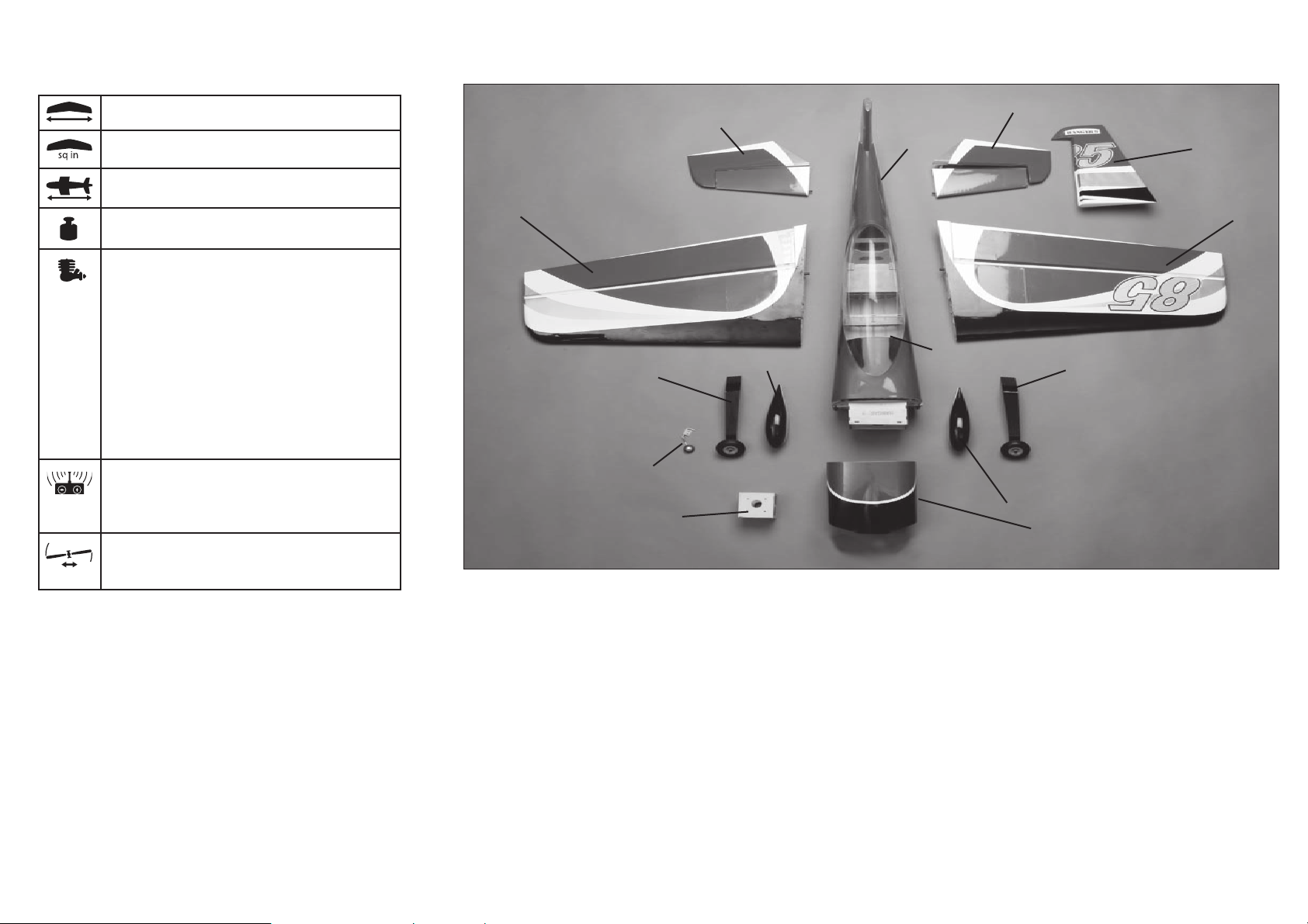
SPECIFICATIONS•SPEZIFIKATIONEN•
SPÉCIFICATIONS•SPECIFICHE
LARGE PARTS LAYOUT•BAUTEILE (OHNE KLEINTEILE)•
ELÉMENTS PRINCIPAUX•SCHEMA DEI COMPONENTI GRANDI
62.0 in (1575mm)
860 sq in (55.5 dm2)
60.0 in (1524mm)
7.5–8.5 lb (3.4–3.9 kg)
2-Stroke Glow•2-Takt Glühzünder•
2 temps méthanol•2-Tempi Glow
.52–.61
4-Stroke Glow•4-Takt Glühzünder•
4 temps méthanol•4-Tempi Glow
.91–1.25
2-Stroke Gas/Petrol•2-Takt Benziner•
2 temps essence•2 tempi a benzina
15cc
Electric Power•Elektro Antrieb•
Moteur électrique (EP)•Motore elettrico
Power 60 Brushless
4-channel (or greater) with 5 servos, 4 for EP
4-Kanal (oder mehr) mit 5 Servos, 4 für Elektroantrieb
4 voies (ou plus) avec 5 servos, 4 pour moteur EP
A 4 canali (o più) con 5 servo, 4 per il motore elettrico
Spinner•Spinner•Cône•Ogiva dell’elica
31/4-inch (82mm) (not included/nicht im
Lieferumfang enthalten/non inclus/non inclusa)
4
1
3
2
8
9
10
7
4
5
3
8
7
6
6
Page 7
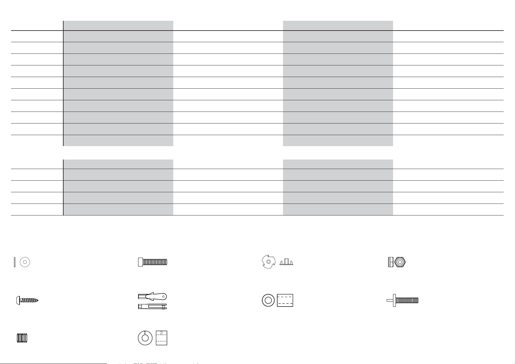
REPLACEMENT PARTS•ERSATZTEILE•PIÈCES DE RECHANGE•RICAMBI
Part English Deutsch Français Italiano
1. HAN421501 Fuselage with Hatch Rumpf mit Haube Fuselage avec trappe Fusoliera con portello
2. HAN421502 Hatch with Canopy Öffnung mit Kabinenhaube Trappe avec verrière Naca pilota
3. HAN421503 Wing Set Tragfl ächenset Paire d’ailes Set ali
4. HAN421505 Stabilizer and Elevator Set Höhenruderset Stabilisateur avec gouverne Set stabilizzatore ed elevatore
5. HAN421507 Rudder Seitenleitwerk Dérive Timone
6. HAN421509 Cowling Motorhaube Capot moteur Carenatura
7. HAN421510 Wheel Pants Radverkleidung Carénage de roue Copriruote
8. HAN421511 Aluminum Landing Gear Fahrwerk aus Aluminium Train d’atterrissage en aluminium Carrello di atterraggio in alluminio
9. HAN421517 Tail Wheel Assembly Spornrad m. Zbh. Assemblage de roulette de queue Gruppo del ruotino di coda
10. HAN421520 EP Mount Set E-Motorhalter Set Support moteur EP Set di montaggio motore elettrico
SMALL PARTS (NOT SHOWN)•KLEINTEILE (NICHT ABGEBILDET)•PETITES PIÈCES (NON REPRÉSENTÉES)•PARTI DI PICCOLE DIMENSIONI (NON MOSTRATE)
HAN421512 Linkage Set Gestängesatz Jeu de commandes Set di tiranti
HAN421513 Assembled Fuel Tank Kraftstofftank montiert Réservoir complet Serbatoio carburante assemblato
HAN421514 Aluminum Wing Tube Tragfl ächenverbinder aus Aluminium Clé d’aile en aluminium Tubo dell’ala in alluminio
HAN421515 Aluminum Stabilizer Tube Leitwerkrohr aus Aluminium Clé de stabilisateur en aluminium Tubo dello stabilizzatore in alluminio
HAN421519 Decal Set Dekorbogen Planche de décoration Set di decalcomanie
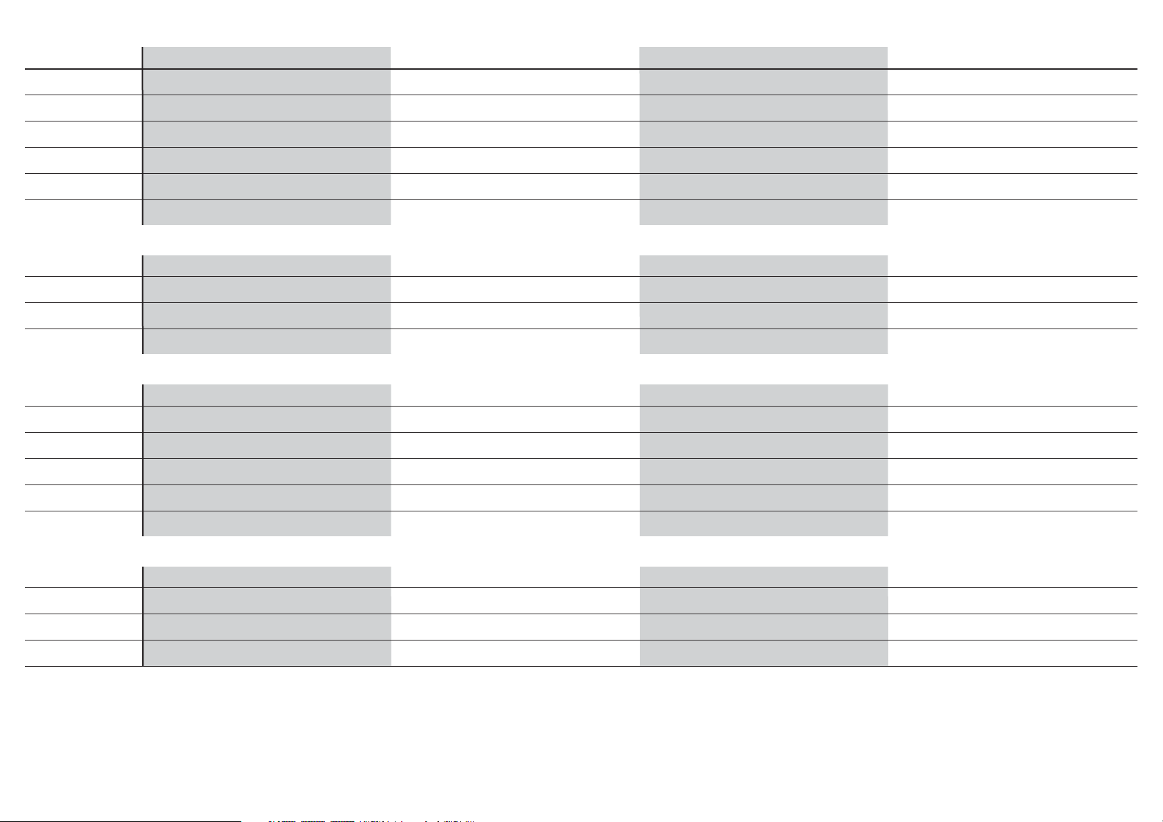
FASTENERS•VERBINDUNGSELEMENTE•ATTACHES•ELEMENTI DI FISSAGGIO
Flat Washer
Unterlegscheibe
Rondelle plate
Rondella piatta
Self-Tapping Screw
Selbstschneidene Schraube
Vis auto-taraudeuse
Vite autofi lettante
Setscrew
Madenschraube
Vis sans tête
Set di viti
Socket Head Cap Screw
Inbusschraube
Vis BTR
Vite a brugola
Nylon Clevis
N
Gabelkopf
Chape nylon
Forcella nylon
Wheel Collar
Stellring
Bague d’arrêt
Collare ruota
Blind nut
Einschlagmutter
Écrou borgne
Dado cieco
Silicone Tubing
Silikonschlauch
Durite silicone
Tubetto silicone
Lock Nut
Stopmutter
Ecrou auto-freiné
Dado di bloccaggio
Nylon Wing Bolt
Tragfl ächenbolzen
Vis nylon de fi xation d’aile
Vite nylon per ali
7
Page 8

ASSEMBLY SYMBOL GUIDE•MONTAGE SYMBOLE•GUIDE DES SYMBOLES POUR ASSEMBLAGE•GUIDA AI SIMBOLI DI ASSEMBLAGGIO
15
30
LRL
R
x2
Apply threadlock
Schraubensicherungslack verwenden
Utilisez du frein fi let
Applicare fuido threadlock
Assemble right and left
Links und rechts montieren
Assemblez à droite et à gauche
Assemblare destra e sinistra
Repeat multiple times
(as indicated)
Vorgang wiederholen
(wie angezeigt)
Répétez comme indiqué
Ripetere piu’ volte
(come indicato)
Ensure free rotation
Rotation sicherstellen
Permettez une rotation libre
Assicurarsi rotazione libera
Push tightly
Fest drücken
Serrez fortement
Spingere forte
Apply oil
Öl verwenden
Appliquez lubrifi ant
Applicare olio
Use medium CA
Mittelfl üssigen
Sekundenkleber verwenden
Utilisez de la colle
cyanoacrylate moyenne
Usare colla ciano acrilica media
Use thin CA
Dünnfl üssigen
Sekundenkleber verwenden
Utilisez de la colle
cyanoacrylate fi ne
Usare colla ciano acrilica fi ne
Use 15-minute epoxy
Verwenden Sie 15 Minuten Epoxy
Utilisez de l’époxy 15 minutes
Usare una resina epossidica con
indurimento di 15 minuti
Use a pencil
Verwenden Sie einen Bleistift
Utilisez un crayon à papier
Usare una matita
Use a felt-tipped pen
Verwenden Sie einen Faserstift
Utilisez un feutre fi n effaçable
Usare un pennarello
Fully tighten
Vollständig festziehen/festschrauben
Serrez complètement
Stringere al massimo
8
Ensure proper orientation
Ausrichtung/Richtung sicherstellen
Vérifi ez la bonne orientation
Assicurarsi dell’appropriato
orientamento
Attach temporarily
Vorübergehend anbringen
Attachez temporairement
Attaccare temporaneamente
Use 30-minute epoxy
Verwenden Sie 30 Minuten Epoxy
Utilisez de l’époxy 30 minutes
Usare una resina epossidica con
indurimento di 30 minuti
Use hobby knife with
#11 blade
Verwenden Sie ein Hobbymesser mit #
11 Klinge
Utilisez un Couteau: Lame numéro 11
Usare taglierino per hobbistica con
lama numero 11
Page 9
REQUIRED RADIO EQUIPMENT•ERFORDERLICHE RC AUSRÜSTUNG•EQUIPEMENT RADIO REQUIS•APPARECCHIATURE RADIO
Part # English Deutsch Français Italiano
SPMAR8000 AR8000 8-Channel DSMX® Receiver AR8000 8-Kanal DSMX Receiver Récepteur 8 voies DSMX AR8000 Ricevitore AR8000 DSMX a 8 canali
JRPS821HV (5, 4 for EP) DS821HV HV Digital Sport High Torque Servo DS821HV HV Digital Sport High Torque Servo Servo DS821 HV digital, couple élevé DS821 HV HV Servo digitale coppia elevata
DUB674 (3) Super Strength Standard Servo Arms: JR Verstärkte Servoarme JR Jr - Palonniers de servos renforcés Squadrette servi rinforzate: JR
SPMB1350LP Li-Po Receiver Pack 1350mAh Li-Po Empfänger Akku Pack 1350mAh Batterie de réception Li-Po 1350mA Batteria LiPo per ricevitore 1350mAh
SPM9532 Deluxe 3-Wire Switch Harness Spektrum Deluxe Schalterkabel mit 3 Anschlüssen Interrupteur à 3 câbles deluxe Interruttore deluxe a 3 fi li
JSP98110 (2) 6-inch Servo Extension Servoverlängerung 15,24cm Rallonge de servo 15cm Prolunga servo 15cm
2-STROKE GLOW•2-TAKT GLÜHZÜNDER•2 TEMPS MÉTHANOL•GLOW 2 TEMPI
EVOE611 Evolution .61NX Glow Engine with Muffl er Evolution .61 Glühzünder mit Schalldämpfer Moteur Evolution .61NX méthanol avec silencieux Motore glow Evolution .61NX con silenziatore
EVO12060 Evolution Propeller 12 x 6 Evolution Propeller 12 x 6 Hélice Evolution 12x6 Elica Evolution 12 x 6
HAN99005 3
1
/4-inch Aluminum Spinner: P51 82mm Aluminum Spinner: P51 Cône en aluminium 82mm type P51 Ogiva alluminio 8,2cm: P-51
HAN99054 5/16 x 24 Prop Adapter Kit 5/16 x 24 Prop Adapter Kit Ecrou adaptateur de cône 5/16 x24 5/16 x 24 Kit adattatore elica
2-STROKE GAS/PETROL•2 TAKT BENZIN MOTOR•2 TEMPS ESSENCE• BENZINA 2 TEMPI
EVOE15GX 15GX 15cc (.91) Gas/Petrol Engine Evolution 15GX 15cc (.91) Benzinmotor Moteur 15GX (.91) essence 15GX 15cc (.91) Motore a benzina
Evolution Propeller Evolution Propeller Hélice Evolution Elica Evolution
HAN99054 5/16 x 24 Prop Adapter Kit 5/16 x 24 Propeller Adapter Kit Ecrou adaptateur de cône 5/16 x24 5/16 x 24 Kit adattatore elica
HAN99005 3
1
/4-inch Aluminum Spinner: P51 82mm Aluminum Spinner: P51 Cône en aluminium 82mm type P51 Ogiva alluminio 8,2cm: P-51
SPMB1350LP Li-Po Receiver Pack, 1350mAh Li-Po Empfänger Akku Pack 1350mAh Batterie de réception Li-Po 1350mA Batteria LiPo per ricevitore 1350mAh
SPM9532 Deluxe 3-Wire Switch Harness Spektrum Deluxe Schalterkabel mit 3 Anschlüssen Interrupteur à 3 câbles deluxe Interruttore deluxe a 3 fi li
4-STROKE GLOW•4-TAKT GLÜHZÜNDER•4 TEMPS MÉTHANOL•4-TEMPI GLOW
SAIE115 FA-115A AAC with Muffl er: AG FA-115A AAC mit Schalldämpfer: AG Moteur FA-115A AAC avec silencieux FA-115A AACcon silenziatore: AG
Propeller, 13 x 8 to 14 x 8 Propeller, 13 x 8 bis 14 x 8 Hélice de 13x8 à 14x8 Elica da 13 x 8 a 14 x 8
HAN99005 3
HAN99052 8 x 1.25 Prop Adapter Kit 8 x 1.25 Prop Adapter Kit Ecrou adaptateur de cône 8 x 1.25 8 x 1.25 Kit adattatore elica
1
/4-inch Aluminum Spinner: P51 31/4-inch Aluminum Spinner: P51 Cône en aluminium 82mm type P51 Ogiva alluminio 8,2cm: P-51
9
Page 10
ELECTRIC POWER•ELEKTROANTRIEB•MOTEUR ELECTRIQUE (EP)•MOTORE ELETTRICO
EFLM4060B Power 60 Brushless Outrunner Motor, 470Kv E-fl ite Power 60 BL AL-Motor 470U/V Moteur Power 60 Brushless à cage tournante 470Kv Power 60 Motore brushless cassa rotante, 470Kv
EFLA1080B 80-Amp Pro Switch-Mode BEC E-fl ite 80-Amp Pro Switch-Mode BEC Contrôleur brushless 80A Pro switch-mode BEC, ESC 80A con BEC switching, EC5 (V2)
Brushless ESC, EC5
EFLB50006S30 5000mAh 6S 22.2V 30C LiPo, 10AWG EC5
™
(V2) Brushless Regler, EC5 (V2) prise EC5 (V2)
™
E-flite 5000mAh 6S 22.2V 30C LiPo, 10AWG EC5 Batterie Li-Po 22.2v 6S 5000mA 30C, EC5 5000mAh 6S 22.2V 30C LiPo, 10AWG EC5
APC17070E Electric Propeller, 17 x 7E Elektro Propeller, 17 x 7E Hélice électrique 17 x 7E Elica per motore elettrico 17 x 7E
HAN99005 3
1
/4-inch Aluminum Spinner: P51 31/4-inch Aluminum Spinner: P51 Cône en aluminium 82mm type P51 Ogiva alluminio 8,2cm: P-51
HAN99052 8 x 1.25 Prop Adapter Kit 8 x 1.25 Prop Adapter Kit Ecrou adaptateur de cône 8 x 1.25 8 x 1.25 Kit adattatore elica
EFLM1934 Prop Adapter: Power 46/52/60 Propelleradapter: Power 46/52/60 Adaptateur d’hélice : 46/52/60 Adattatore dell’elica: Power 46/52/60
OPTIONAL ITEMS•OPTIONALE TEILE•ELÉMENTS OPTIONNELS•ARTICOLI OPZIONALI
EFLA110 Power Meter E-fl ite Lastmessgerät Wattmètre Misuratore di potenza
EFLC3020 Celectra
™
200W DC Charger E-fl ite 200W DC Multi-Akku Ladegerät Chargeur CC 200W Celectra Celectra 200W DC Caricabatterie
LOSA99201 Self-Stick Weights, 3 oz Selbstklebe Chassisgewichte 3 oz Poids autocollants, 85 grammes Pesi auto-adesivi da 93 gr
REQUIRED ADHESIVES•ERFORDERLICHE KLEBSTOFFE•TYPES DE COLLES•ADESIVI NECESSARI
PAAPT35 15-Minute Epoxy 15 Minuten Epoxy Époxy 15 minutes Colla epoxy 15 minuti
PAAPT38 5-minute Epoxy 5 Minuten Epoxy Époxy 5 minutes Colla epoxy 5 minuti
PAAPT09 Thin CA Sekundenkleber dünnfl üssig Colle cyano fi ne Cianoacrilica fine
PAAPT03 Medium CA Sekundenkleber mittel Colle cyano moyenne Medio CA
PAAPT42 Threadlock Schraubensicherungslack Frein-filet Frenafiletti
10
Page 11

REQUIRED TOOLS•BENÖTIGTES WERKZEUG•OUTILS REQUIS•ATTREZZI NECESSARI
English Deutsch Français Italiano
Drill bit: 1/16-inch, 5/64-inch, 1/8-inch, 11/64-inch Bohrer: 1,5 mm, 2mm, 3mm, 4,5mm Foret : 1,5 mm, 2mm, 3mm, 4,5mm Punte per trapano: 1,5 mm, 2mm, 3mm, 4,5mm
Felt-tipped pen Faserstift Feutre fi n effaçable PennarelloFlat blade screwdriver: Small
Hemostat Klemme Pince Hemostat Pinzetta
Hex wrench: 1.5mm, 2mm, 2.5mm, 3mm, 3/32-inch, 7/64-inch Inbusschlüssel: 1,5mm, 2mm, 2,5mm, 3mm, 3/32-inch, Tournevis hexagonal : 1.5mm, 2mm, 2,5mm, 3mm, 3/32-inch, Chiave esag.: 1.5mm, 2mm, 2,5mm, 3mm,
7/64-inch 7/64-inch 3/32-inch, 7/64-inch
Hobby and craft square Rechteck Equerre de modélisme Riga a squadra
Hobby knife: #11 blade Hobbymesser mit # 11 Klinge Couteau : Lame numéro 11 Taglierino: #11 lama
Isopropyl alcohol Isopropyl Alkohol Alcool isopropylique Alcol isopropilico
Mixing cups and sticks Mischbecher und Rührstäbchen Récipients pour mélanger et bâtons Contenitori e stick per mixer colla
Nut driver: 11/32-inch Steckschlüssel. 11/32 inch Clés à douilles : 11/32 pouce Chiave per dadi:8,7 mm
Paper towels Papiertücher Papier absorbant Asciugamani di carta
Pencil Stift Crayon à papier Matita
Phillips screwdriver: #1, #2 Phillips Schraubendreher: #1,#2 Tournevis cruciforme: #1, #2 Cacciavite a croce: #1, #2
Pin vise Handbohrer Porte forets Trapano manuale
Pliers Zange Pince Pinze
Razor saw Säge Lame de rasoir Sega Razor
Reamer Reibahle Alésoir Alesatore
Rotary tool elektrischer Handbohrer Multiutensilie Utensile rotante
Ruler Lineal Réglet Righello
Sanding drum Schleiftrommel Poncette rotative Levigatore
Sandpaper Schleifpapier Papier de verre Carta vetrata
Scissors Schere Ciseaux Forbici
Side cutters Seitenschneider Pince coupante Lama laterale
T-pins T- Nadeln Epingles Spilli a T
11
Page 12

BEFORE STARTING ASSEMBLY
VOR DEM ZUSAMMENBAU
AVANT DE COMMENCER L’ASSEMBLAGE
PRIMA DI INIZIARE IL MONTAGGIO
• Remove parts from bag.
• Inspect fuselage, wing panels, rudder and stabilizer for
damage.
• If you fi nd damaged or missing parts, contact your place
of purchase.
If you fi nd any wrinkles in the covering, use a heat gun
(HAN100) and covering glove (HAN150) or covering iron
(HAN101) with a sealing iron sock (HAN141) to remove them.
Use caution while working around areas where the colors
overlap to prevent separating the colors.
• Charge transmitter and receiver batteries.
• Center trims and sticks on your transmitter.
• For a computer radio, create a model memory for this
particular model.
• Bind your transmitter and receiver, using your radio
system’s instructions.
IMPORTANT: Rebind the radio system once all control
throws are set. This will keep the servos from moving to their
endpoints until the transmitter and receiver connect. It will
also guarantee the servo reversal settings are saved in the
radio system.
• Entnehmen Sie zur Überprüfung jedes Teil der Verpackung.
• Überprüfen Sie den Rumpf, Tragfl ächen, Seiten- und
Höhenruder auf Beschädigung.
• Sollten Sie beschädigte oder fehlende Teile feststellen,
kontaktieren Sie bitte den Verkäufer.
Zum Entfernen von Falten in der Bespannung verwenden
Sie den Heißluftfön (HAN100) und Bespannhandschuh
(HAN150) oder das Folienbügeleisen (HAN141). Bitte achten
Sie bei überlappenden Farben, dass Sie diese sich bei dem
Bearbeitung nicht trennen.
• Laden des Senders und Empfängers.
• Zentrieren der Trimmungen und Sticks auf dem Sender.
• Sollten Sie einen Computersender verwenden, resetten Sie
einen Speicherplatz und benennen ihn nach dem Modell.
• Sender und Empfänger jetzt nach den Bindeanweisung
des Herstellers zu binden.
WICHTIG: Wir empfehlen dringend nachdem alle
Einstellungen vorgenommen worden sind, das Modell
neu zu binden. Dieses verhindert, dass die Servos in die
Endanschläge laufen bevor sich Sender und Empfänger
verbunden haben. Es garantiert auch, dass die
Servoreverseeinstellungen in der RC Anlage gesichert sind.
• Retirez toutes les pièces des sachets pour les inspecter.
• Inspectez soigneusement le fuselage, les ailes et les
empennages.
• Si un élément est endommagé, contactez votre revendeur.
Si l’entoilage présente quelques plis, vous pouvez les lisser
en utilisant le pistolet à air chaud (HAN100) et le gant
(HAN150) ou le fer à entoiler (HAN101) avec la chaussette de
protection (HAN141). Agissez soigneusement dans les zones
ou plusieurs couleurs d’entoilage sont superposées afi n
d’éviter de les séparer.
• ll est recommandé de préparer tous les éléments du
système de la radio.
• Cela inclut, la charge des batteries comme la mise au
neutre des trims et des manches de votre émetteur.
• Si vous utilisez une radio programmable, sélectionnez une
mémoire libre afi n d’y enregistrer les paramètres de ce
modèle.
• Nous vous recommandons d’affecter maintenant le
récepteur à l’émetteur en suivant les instructions fournies
avec votre radio.
IMPORTANT: Il est hautement recommandé de
ré-affecter le système une fois que les courses seront
réglées. Cela empêchera les servos d’aller en butée lors de
la connexion du système. Cela garantit également que la
direction des servos est enregistrée dans l’émetteur.
• Togliere tutti i pezzi dalla scatola.
• Verifi care che la fusoliera, l’ala e i piani di coda non siano
danneggiati.
• Se si trovano parti danneggiate, contattare il negozio da
cui è stato acquistato.
Se si trovano delle pieghe nella ricopertura, si possono
togliere usando una pistola ad aria calda (HAN100) e guanto
per ricopertura (HAN150), oppure un ferro per ricopertura
(HAN101) con la sua calza di protezione (HAN141). Usare
cautela quando si lavora in aree del rivestimento dove ci
sono dei colori sovrapposti, per evitare la loro separazione.
• Caricare il trasmettitore e la batteria di volo.
• Centrare stick e trim sul trasmettitore.
• Con una radio computerizzata creare una nuova memoria
per questo modello.
• Facendo riferimento alle istruzioni del radiocomando,
connettere (bind) trasmettitore e ricevitore.
IMPORTANTE: Ripetere la procedura di connessione
una volta regolate le corse, per evitare che i servi vadano a
fi ne corsa. Garantirà anche che le impostazioni di inversione
del servo vengano salvate nel sistema radio.
12
Page 13
LRL
R
LRL
R
LRL
R
LRL
R
AILERON SERVO INSTALLATION•EINBAU DER QUERRUDERSERVOS•INSTALLATION DES SERVOS D’AILERONS•INSTALLAZIONE SERVI ALETTONI
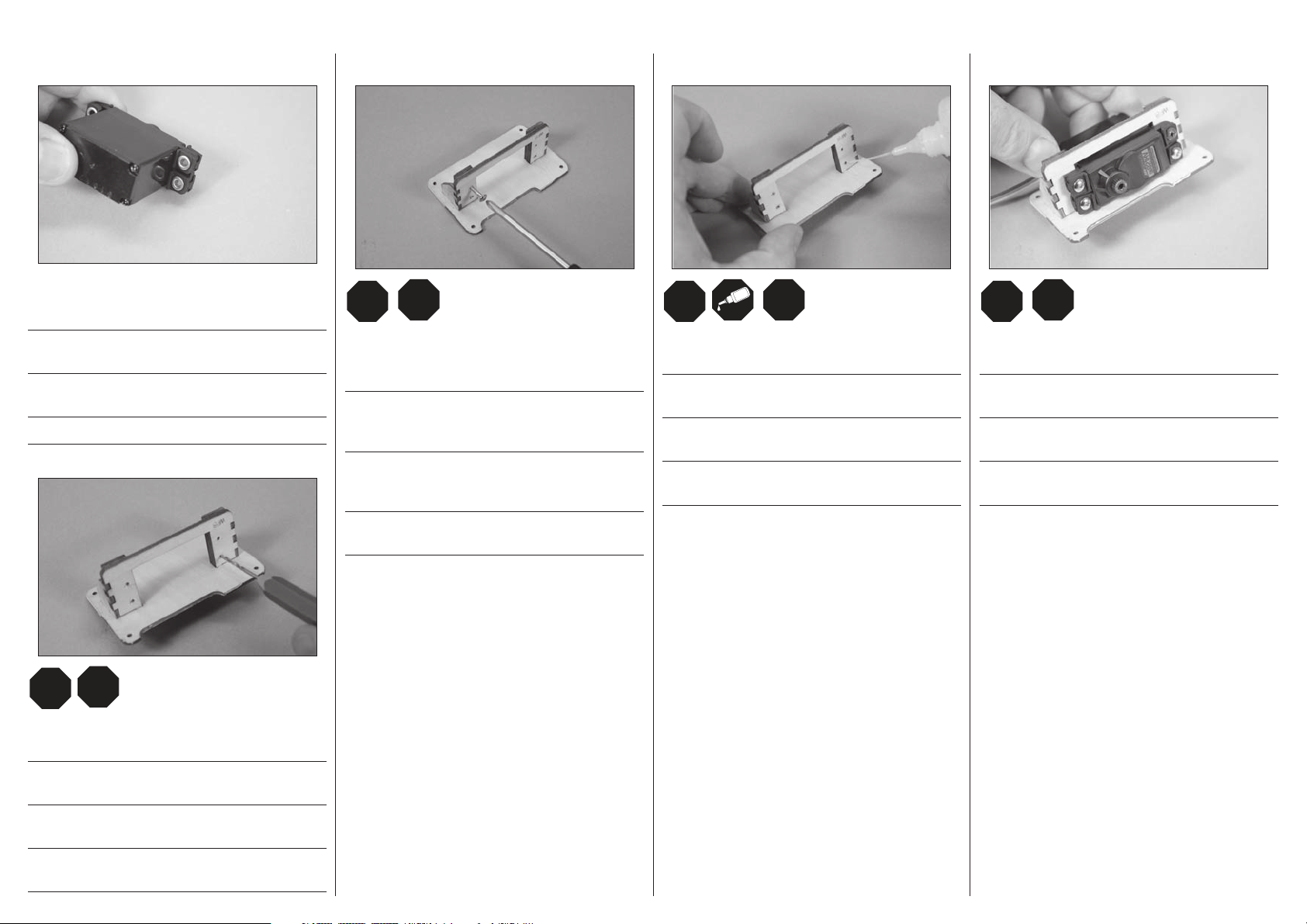
1
Prepare the aileron servos by installing the grommets and
eyelets.
Setzen Sie in die Querruderservos die Gummitüllen und
Blechösen ein.
Préparez les servos d’ailerons en les équipant de leurs
silent-blocs.
Preparare i servi montando gommini e distanziali.
2
3
Thread a servo mounting screw into each of the holes in the
aileron servo mounting holes. Remove the screws before
proceeding.
Drehen Sie in jedes Servobefestigungsloch einmal eine
Servoschraube. Entfernen Sie die Schrauben bevor Sie weiter
machen.
Visser une vis de montage de servo dans chacun des trous
de montage du servo d’aileron. Redévisser les vis avant de
poursuivre.
4
Apply a small amount of thin CA to harden the threads made
in the previous step.
Geben Sie einen kleinen Tropfen dünnfl üssigen
Sekundenkleber in die Gewindelöcher um diese zu härten.
Appliquer une petite quantité de colle cyano fi ne pour durcir
les fi letages faits lors de l’étape précédente.
Mettere una piccola quantità di colla CA nei fori, per indurire
il fi letto fatto nel passaggio precedente.
Secure the servo to the cover using the screws provided with
the servo.
Befestigen Sie das Servo mit den mitgelieferten Schrauben
an der Abdeckung.
Fixer le servo à la trappe à l’aide des vis fournies avec le
servo.
Fissare il servo alla copertura usando le viti fornite insieme
al servo stesso.
5
Use a pin vise and 5/64-inch (2mm) drill bit to drill the holes
for the servo mounting screws.
Bohren Sie mithilfe eines Feilklobens und eines 2-mmBohrers die Löcher für die Servo-Befestigungsschrauben.
Utiliser un porte-foret et un foret de 2 mm pour percer les
trous destinés aux vis de fi xation du servo.
Usare una morsa stretta e una punta per trapano da 2 mm
per fare i fori per le viti di montaggio del servo.
Avvitare una vite per il montaggio dei servi in ognuno dei fori
del supporto servi alettoni. Svitare le viti prima di procedere.
13
Page 14
LRL
R
LRL
R
LRL
R
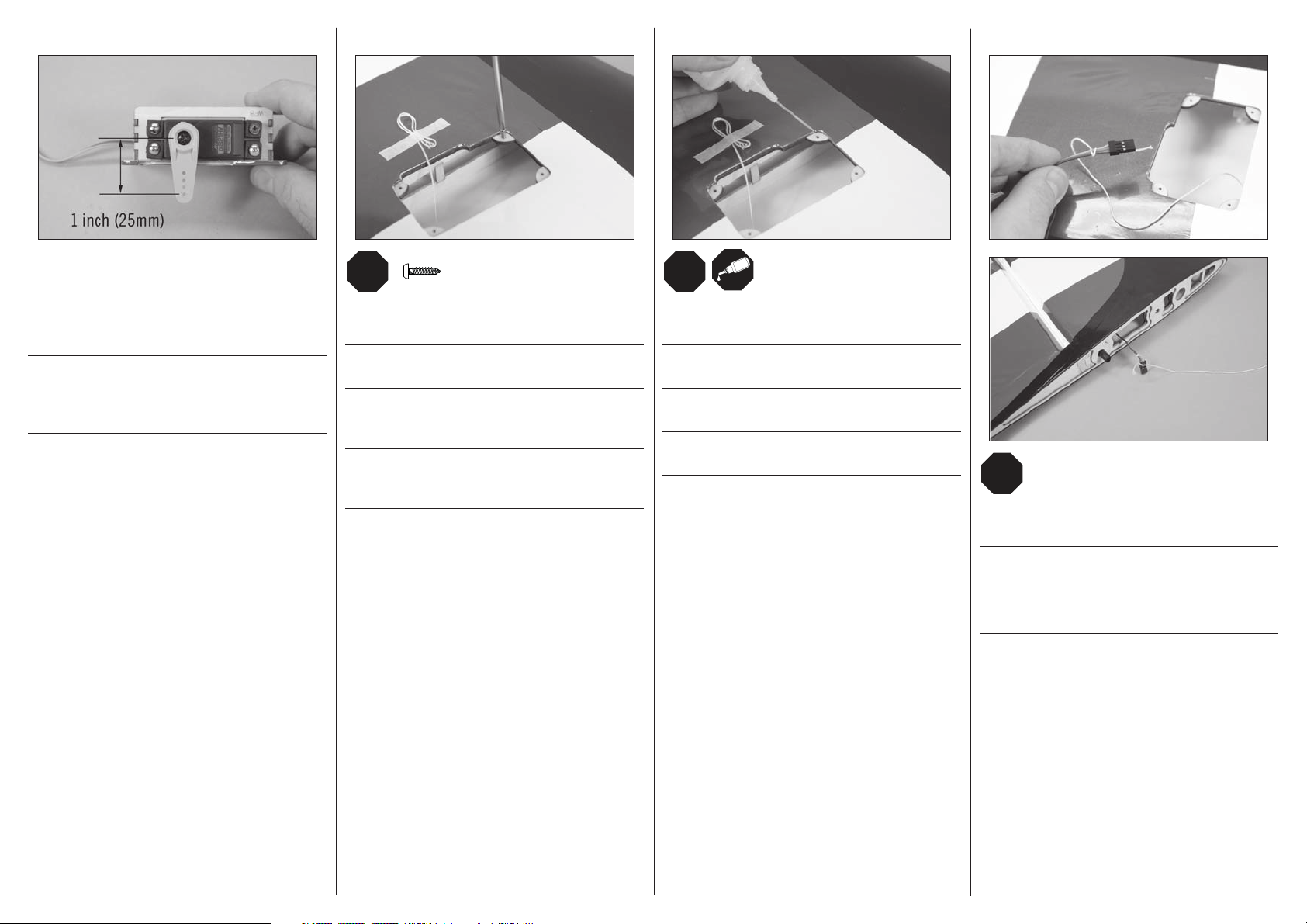
6
Center the servos using the radio system and install the
servo arms so they are perpendicular to the servo center line.
Enlarge the hole in the servo arm using a 5/64-inch (2mm)
drill bit that is 1 inch (25mm) from the center of the servo
arm for the aileron linkage.
Zentrieren Sie die Servos mit der Fensteuerung und setzen
die Servoarme rechtwinklig zur Servomittenlinie auf.
Vergrößern Sie das Loch im Ruderhorn das 25mm von der
Mitte entfernt mit einem 2mm Bohrer.
Mettez les servos au neutre en utilisant la radio et en
installant les bras à la perpendiculaire de la ligne centrale
des servos. Agrandissez à l’aide d’un foret de 2mm le trou se
situant à une distance 25mm du centre du servo.
Centrare i servi con il radiocomando e montare le squadrette
in modo che siano perpendicolari alla linea centrale del
servo. Allargare il foro che si trova a 25mm dal centro della
squadretta con una punta da 2mm per collegare il comando
dell’alettone.
7
M2 x 10
x4
Thread a screw into each of the holes in the aileron servo
cover mounting holes. Remove the screws before proceeding.
Drehen Sie in jedes Loch der Servoabdeckung eine Schraube.
Entfernen Sie die Schrauben bevor Sie weiter machen.
Visser une vis dans chacun des trous de montage de
la trappe du servo d’aileron. Enlever les vis avant de
poursuivre.
Avvitare una vite in ognuno dei fori a cui andrà fi ssato
il coperchio con il servo alettoni. Togliere le viti prima di
procedere.
8
Apply a small amount of thin CA to harden the threads made
in the previous step.
Geben Sie einen kleinen Tropfen dünnfl üssigen
Sekundenkleber in die Gewindelöcher um diese zu härten.
Appliquer une petite quantité de colle cyano fi ne pour durcir
les fi letages faits lors de l’étape précédente.
Mettere una piccola quantità di colla CA nei fori, per indurire
il fi letto fatto nel passaggio precedente.
9
Tie the string located inside the wing to the end of the servo
lead. Use the string to pull the servo lead through the wing.
Knoten Sie das Ende der Schnur in der Tragfl äche um das
Servokabel. Ziehen Sie die Schnur durch die Tragfl äche.
Nouez de la fi celle autour de la prise de servo de la rallonge.
Tirez la prise à travers l’aile.
Legare lo spago che si trova all’interno dell’ala al connettore
del servo. Usare lo spago per tirare il connettore all’interno
dell’ala.
14
Page 15
LRL
R
LRL
R
LRL
R
10
11
12
LANDING GEAR INSTALLATION•
EINBAU DES FAHRWERKS•
INSTALLATION DU TRAIN
D’ATTERRISSAGE•
INSTALLAZIONE DEL CARRELLO
1
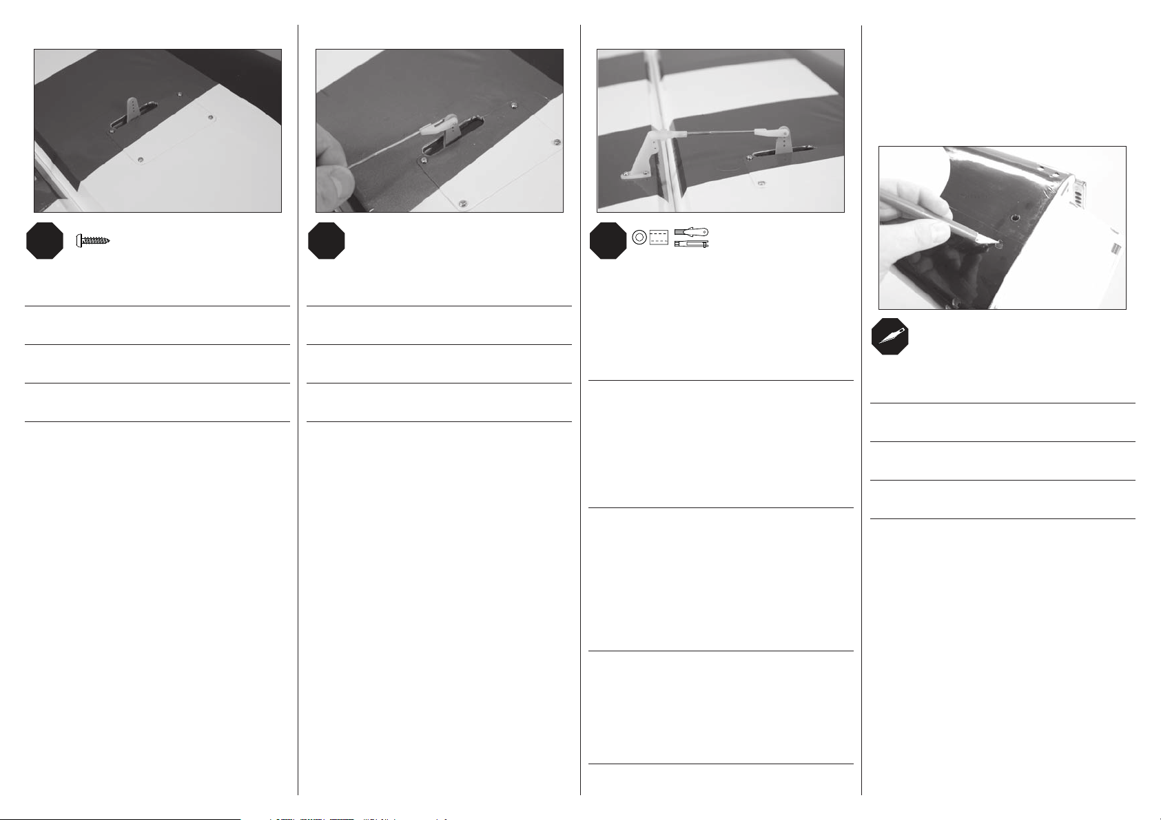
M2 x 10
x4
Secure the servo cover to the wing using four M1.5 x 10 selftapping screws.
Schrauben Sie die Servoklappe an die Tragfl äche mit den vier
M1.5 x 10 selbstschneidenen Schrauben.
Fixer le couvercle de servo à l'aide de 4 vis auto-taraudeuses
M1.5 x 10.
Fissare la copertura del servo all'ala usando quattro viti
autofilettanti M1.5 x 10.
Attach the 213/16-inch (72mm) linkage to the servo arm using
the nylon connector.
Schließen Sie mit dem Gabelkopf das 72mm Gestänge an
das Servohorn an.
Reliez la tringlerie de 72mm au bras de servo en utilisant le
connecteur en nylon.
Collegare la barretta di comando da 72mm alla squadretta
del servo con la forcella in nylon.
N
x2
Slide a silicone retainer over the clevis. Thread the clevis on
the pushrod. With the aileron servo plugged into the receiver,
turn on the radio system and center the aileron servo. Adjust
the clevis so the aileron is centered when the clevis is
attached to the outer hole of the aileron control horn. Once
attached, slide the retainer over the forks of the clevis to
keep it from opening accidentally.
Schieben Sie den Silikonschlauch über den Gabelkopf.
Drehen Sie den Gabelkopf auf das Gestänge. Zentrieren
Sie mit der eingeschalteten Anlage das Querruderservo.
Justieren Sie das Gestänge so dass das Querruder
zentriert ist wenn der Gabelkopf im äußersten Loch des
Querruderhorn steckt. Schieben Sie nach dem Anschluss den
Silikonschlauch zur Sicherung wieder über den Gabelkopf,
damit er sich nicht versehentlich öffnen kann.
Glissez un morceau de durite silicone sur la chape. Vissez
la chape sur la tringlerie. Avec le servo relié au récepteur,
mettez votre système radio sous tension et placez le servo
au neutre. Ajustez la longueur de la tringlerie en tournant la
chape de façon à centrer le volet d’aileron quand la chape
est insérée dans le trou extérieur du guignol. Une fois que
la chape est reliée au guignol, glissez le morceau de tube
silicone sur les fourches de la chape pour empêcher son
ouverture accidentelle.
x2
Remove the covering to provide access to the two inner holes
for the landing gear bolts.
Entfernen Sie die Folie aus den Löchern für die
Fahrwerksschrauben.
Retirez l’entoilage recouvrant les deux trous intérieurs de
fi xation du train d’atterrissage.
Togliere la copertura per accedere alle due viti più interne
del carrello.
Infi lare un tubetto in silicone sulla forcella, avvitandola
alla barretta. Con i connettori dei servi alettoni collegati al
ricevitore, accendere il radiocomando per centrare i servi.
Regolare la posizione delle forcelle per centrare gli alettoni
inserendole nel foro più esterno della squadretta collegata
all’alettone. Fatto questo, riportare il tubetto in silicone sulla
forcella per evitare che si apra accidentalmente.
15
Page 16
2
3
RUDDER INSTALLATION•EINBAU DES SEITENRUDERS•
INSTALLATION DE LA DÉRIVE•INSTALLAZIONE DEL TIMONE
1
#4
4-40 x 1/2-inch
2
6-32 x 5/8 inch
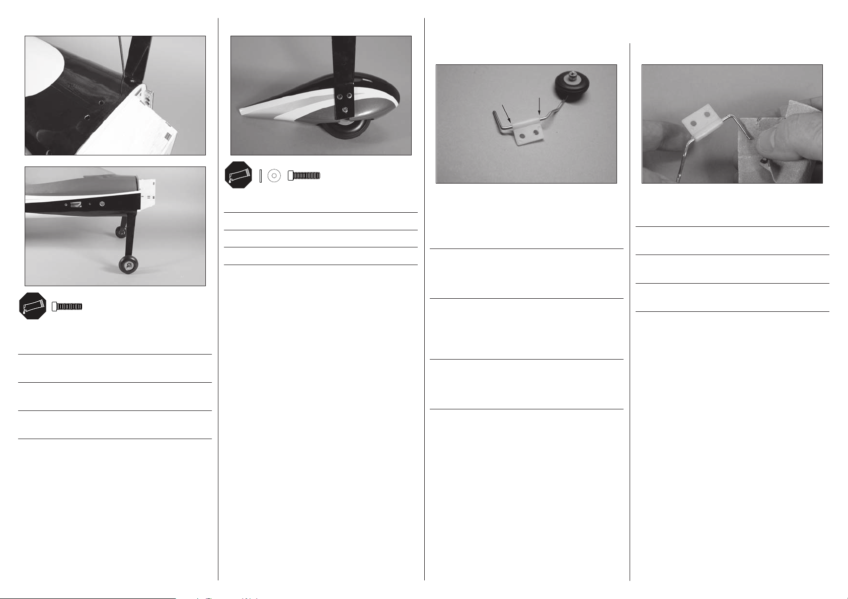
Attach the landing gear to the fuselage, making sure they
rake rearward when installed.
Schrauben Sie das Fahrwerk an den Rumpf und achten
darauf, dass es nach hinten zeigt.
Fixez le train d’atterrissage au fuselage, les jambes doivent
être orientées vers l’arrière.
Fissare il carrello alla fusoliera, accertandosi che, una volta
fi ssato, sia inclinato all’indietro.
x6
x4
Attach the wheel pants to the landing gear.
Schrauben Sie die Radschuhe an das Fahrwerk.
Fixez le carénage de roue à la jambe de train.
Fissare al carrello le carenature delle ruote.
x4
Apply a small amount of petroleum jelly to the tail gear wire
near the bushing. Slide the bushing up and down on the
wire to work the petroleum jelly into the bushing. This helps
prevent the adhesives from gluing the bushing to the wire.
Geben Sie etwas Vaseline auf den Spornraddraht neben dem
Halter. Schieben Sie den Halter hoch und runter und verteilen
damit die Vaseline darunter. Das verhindert das der Halter
am Draht festgeklebt wird.
Appliquez une petite quantité de gelée de pétrole sur la tige
de la roulette de queue autour du palier. Faites glisser le
palier de haut en bas pour faire rentrer de la gelée dans le
palier. Cela permet d’éviter que de la colle vienne coller le
palier à la tige.
Applicare una piccola quantità di vaselina sulla gamba del
carrello posteriore, vicino alla bussola, facendola scorrere in
su e in giù per far entrare la vaselina. Questo per evitare che
la colla blocchi la gamba del carrello.
Use sandpaper to lightly sand the tail wheel wire where it
will be inserted into the rudder.
Rauen Sie mit Schleifpapier den Teil des Spornradhalters an
der in das Ruder gesteckt wird.
Utilisez du papier de verre pour gratter la partie de la tige
qui sera insérée dans la dérive.
Carteggiare leggermente la parte della gamba del carrello
che entra nel timone.
16
Page 17

3
4
5
6
5
Use a small amount of epoxy to glue the bushing into the
fuselage. Slide the bushing down so it is positioned at the
bottom of the pre-cut slot at the rear of the fuselage.
Kleben Sie mit etwas Epoxi das Gestänge in den Rumpf.
Schieben Sie den Halter so in den Schlitz, dass er an der
unteren Seite des Schlitzes ist.
Utilisez de la colle epoxy pour coller le palier dans le
fuselage. Glissez le palier vers le bas de la fente prédécoupée à l’arrière du fuselage.
Incollare con epoxy la bussola alla fusoliera, inserendola
nell’apposita fessura.
Use a pin vise and 1/16-inch (1.5mm) drill bit to drill a hole
in the center of each hinge slot. This allows the CA to wick
into the hinge. Drill holes in both the rudder and fi n surfaces
at this time.
Bohren Sie mit einem 1,5mm Handbohrer ein Loch in die
Mitte jedes Scharnierschlitzes. Dieses ermöglicht dem
Sekundenkleber besser einzudringen. Bohren Sie die Löcher
in Ruder und Finne gleichzeitig.
Utilisez un porte-foret et un foret de 1.5mm pour percer un
trou au centre de chaque rainure de charnière. Cela permet
une meilleure pénétration de la colle CA au niveau de la
charnière. Effectuez les trous dans la dérive et la gouverne
durant cette étape.
Con una punta da 1,5mm praticare un foro al centro di
ogni fessura prevista per l’inserimento delle cerniere.
Questo permette alla colla CA di scorrere fi no al centro della
cerniera. Questo va fatto sia sul direzionale che sul timone.
Use a pin vise and 1/8-inch (3mm) drill bit to drill a hole in
the rudder that is 15/32 inches (30mm) up from the bottom of
the rudder for the tail wheel wire.
Bohren Sie mit dem 3mm Handbohrer ein Loch in das Ruder
für den Spornraddraht dass 30mm von der unteren Kante
entfernt ist.
Utilisez un porte-foret et un foret de 3mm pour percer un trou
dans la gouverne de dérive à une distance de 30 mm à partir
du bas, pour y insérer la tige de la roulette de queue.
Con una punta da 3mm forare il timone a 30mm dal basso,
per inserire poi la gamba del carrello.
Cut a slot from the hole drilled in the previous step to the
bottom of the rudder to fi t over the tail wheel bushing.
Schneiden Sie einen Schlitz von dem Loch dass Sie im
vorherigen Schritt gebohrt haben nach unten damit Platz für
den Spornradhalter ist.
Découpez une rainure qui part du trou précédemment percé
et qui va vers le bas de la dérive afi n de pouvoir y loger le
palier de la roulette de queue.
Dal foro fatto prima, tagliare una fessura che vada fi no in
fondo al timone (in basso), per l’inserimento della gamba
del carrello.
17
Page 18
7
x3
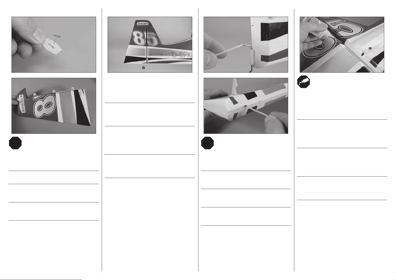
Place a T-pin in the center of the hinge. Slide the hinges
into position with the T-pin resting against the edge of the
control surface.
Setzen Sie eine T-Nadel in die Mitte jedes Scharnieres.
Schieben Sie die Scharniere bis zur Nadel ein.
Insérez une épingle en “T” au milieu de chaque charnière.
Glissez les charnières en position en plaquant l’épingle
contre l’arrête de la gouverne.
Mettere uno spillo con testa a T al centro delle cerniere,
inserendole in posizione fi nché lo spillo si appoggia al bordo
della superfi cie mobile.
8
Check the fi t of the rudder to the fuselage. Make sure the tail
wheel wire fi ts into the rudder, and that the notch fi ts over
the tail wheel bushing. There should be no gap between the
fi n and rudder.
Überprüfen Sie die Passung des Ruders im Rumpf. Bitte
achten Sie darauf dass der Spornraddraht in das Ruder paßt
und der Halter in die Kerbe. Es sollte keine Lücke zwischen
Finne und Ruder sein.
Contrôlez l’ajustement de la gouverne de dérive avec le
fuselage. Contrôlez que la tige de la roulette de queue
s’emboîte parfaitement dans la gouverne et que le palier
s’insère correctement dans la rainure. Il ne doit pas il y avoir
d’écart entre la dérive et le fuselage.
Verifi care che il timone sia ben adattato alla fusoliera, che la
gamba del carrello sia inserita nel timone e che l’incavo sia
sopra alla bussola. Non ci deve essere fessura tra il timone
e il direzionale.
9
5
Apply a small amount of epoxy on the tail gear wire and
rudder where they contact each other. Place the rudder back
into position, fi tting the rudder tightly against the fi n.
Geben Sie etwas Epoxy auf den Spornraddraht und das
Seitenruder wo sie Kontakt haben. Setzen Sie das Ruder
zurück in Position und drücken es an die Finne.
Appliquez de la colle époxy dans le trou qui va recevoir la
tige de la roulette de queue, et placez la dérive en position
contre le fuselage.
Mettere un po’ di colla epoxy dove la gamba del carrello
entra in contatto con il timone. Rimettere il timone in
posizione appoggiandolo bene al direzionale.
10
Once the epoxy fully cures, apply thin CA to both sides of
each hinge. Once the CA cures, gently pull on the fi xed
surface and control surface to make sure the hinges are
glued securely. If not, apply additional CA to secure each of
the hinges.
Geben Sie nachdem das Epoy vollständig getrocknet auf
jede Scharnierseite Sekundenkleber. Ziehen Sie nachdem
der Sekundenkleber getrocknet ist an dem Ruder um zu
überprüfen ob die Klebung einwandfrei ist. Kleben Sie falls
notwendig nach.
Une fois que l’époxy est sèche, appliquez de la colle CA de
chaque côté de chaque charnière. Une fois que la colle est
sèche tirez délicatement sur la gouverne pour contrôler le
collage. Si le collage n’est pas parfait, ré-appliquez de la
colle CA sur chaque charnière.
Quando la colla epoxy è asciutta, mettere la colla CA liquida
su entrambi i lati di ogni cerniera. Quando è asciutta tirare
gentilmente per verifi care che l’incollaggio sia perfetto.
Altrimenti mettere dell’altra colla CA sulle cerniere.
18
Page 19
RUDDER SERVO INSTALLATION•EINBAU DES SEITENRUDERSERVOS•INSTALLATION DU SERVO DE DIRECTION•INSTALLAZIONE SERVO DEL TIMONE
1
2
3
4
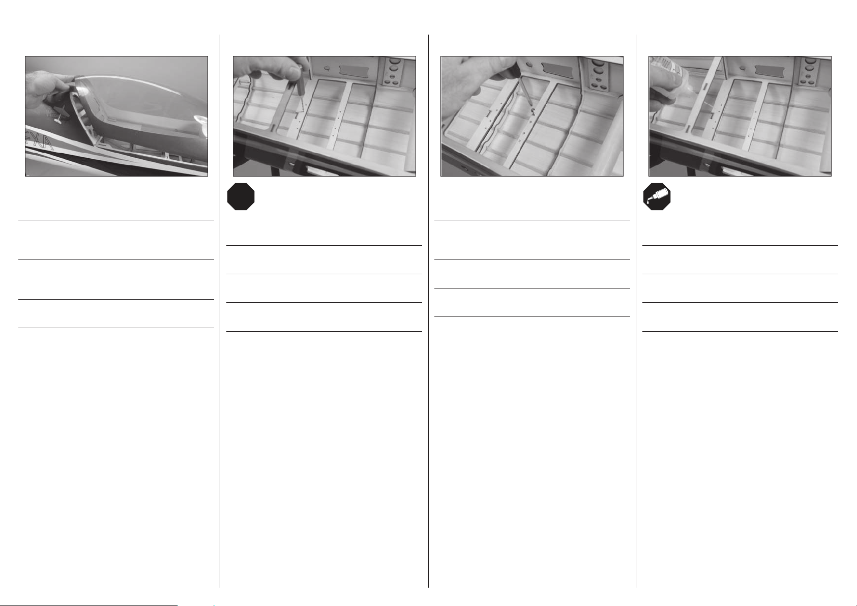
Slide the canopy hatch forward and up to release, then aft to
remove it from the fuselage.
Schieben Sie die Kabinenhaube nach vorne und anschließend
nach oben, um sie zu lösen. Entfernen Sie sie anschließend
vom Rumpf, indem Sie sie zurückschieben.
Faire glisser le cockpit vers l’avant et le soulever pour le
libérer, puis le tirer ensuite vers l’arrière pour l’extraire du
fuselage.
Far scorrere in avanti il portello a calotta fi no a sbloccarlo,
poi all’indietro per rimuoverlo dalla fusoliera.
Use a pin vise and 5/64-inch (2mm) drill bit to drill the holes
for the servo mounting screws.
Bohren Sie mithilfe eines Feilklobens und eines 2-mmBohrers die Löcher für die Servo-Befestigungsschrauben.
Utiliser un porte-foret et un foret de 2 mm pour percer les
trous destinés aux vis de fi xation du servo.
Usare una morsa stretta e una punta per trapano da 2 mm
per fare i fori per le viti di montaggio del servo.
Thread a servo mounting screw into each hole to cut threads
in the surrounding wood.
Drehen Sie in jede Bohrung eine ServoBefestigungsschraube, um ein Gewinde in das Holz zu
schneiden.
Visser une vis de fi xation de servo dans chaque trou pour
créer un fi letage dans le bois.
Avvitare una vite per il montaggio dei servo in ciascun foro
per eseguire dei fi letti nel legno circostante.
Apply a small amount of thin CA to harden the threads made
in the previous step.
Geben Sie einen kleinen Tropfen dünnfl üssigen
Sekundenkleber in die Gewindelöcher um diese zu härten.
Appliquer une petite quantité de colle cyano fi ne pour durcir
les fi letages faits lors de l’étape précédente.
Mettere una piccola quantità di colla CA nei fori, per indurire
il fi letto fatto nel passaggio precedente.
19
Page 20
5
Install the grommets and brass eyelets in the rudder servo.
Secure the rudder servo in the fuselage using the screws
provided with the servos.
Setzen Sie die Gummipuffer und Blechösen in das
Seitenruderservo ein und schrauben es mit den
mitgelieferten Schrauben fest.
Installez les silent-blocs sur le servo de dérive. Fixez le servo
au fuselage en utilisant les vis fournies avec le servo.
Montare gommini e distanziali sul servo del timone. Fissare
il servo in fusoliera usando le viti fornite con i servi.
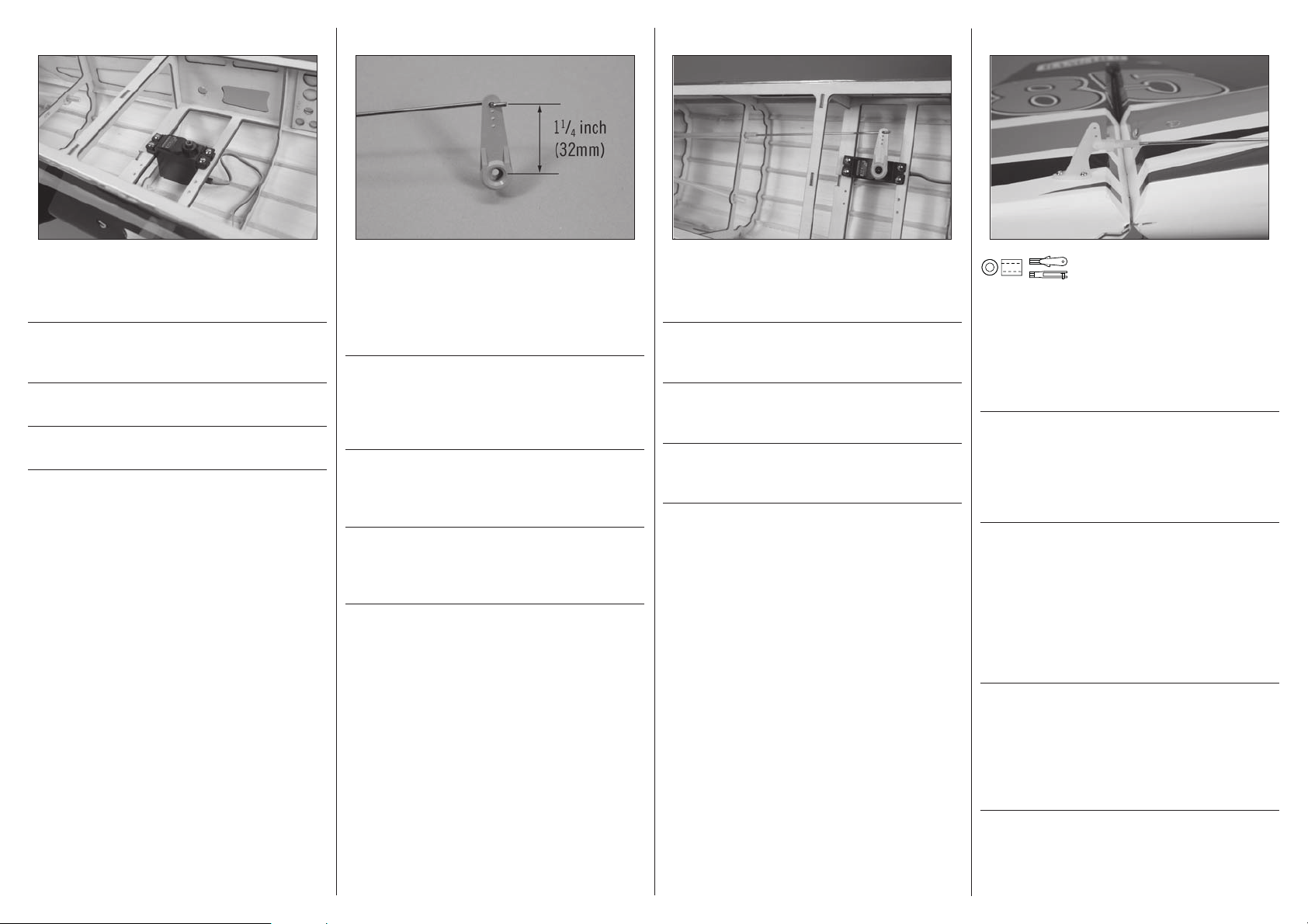
6
Insert the Z-bend of the 2911/16-inch (755mm) pushrod in the
servo arm to be used for the rudder. The pushrod will be 11/
inches (32mm) from the center of the servo arm. Use a pin
vise and 5/64-inch (2mm) drill bit to enlarge the hole before
inserting the pushrod.
Setzen Sie das Z-gebogene Ende des 755mm Gestänges
in den Servoarm des Seitenruders ein. Das Gestänge sollte
in das Loch das 32mm von der Servomitte entfernt ist
eingesetzt werden. Vergrößern Sie es vorher mit einem 2mm
Bohrer.
Utilisez un porte-foret et un foret de 2mm pour agrandir le
trou du bras de servo se situant à une distance de 32mm
du centre. Insérez la partie en “Z” de la tringlerie (755mm)
dans le trou du bras de servo.
Inserire la piegatura a Z della barretta da 755mm nel foro
che si trova a 32mm dal centro sulla squadretta del servo.
Allargare il suddetto foro con una punta da 2mm prima di
inserire la barretta.
7
Slide the rudder pushrod into the pushrod tube. Use the radio
system to center the rudder servo. Attach the servo arm to
4
the servo so it is perpendicular to the servo center line.
Schieben Sie das Seitenrudergestänge in das Röhrchen.
Zentrieren Sie mit der Fernsteuerung das Servo und setzen
den Servoarm rechtwinklig auf.
Glissez la tringlerie dans la gaine. Utilisez la radio pour
mettre le servo au neutre. Fixez le bras de servo au servo en
le plaçant à la perpendiculaire de celui-ci.
Inserire la barretta nel suo tubetto. Centrare il servo
con il radiocomando in modo che la sua squadretta sia
perpendicolare rispetto alla linea centrale.
8
N
x2
Slide a silicone retainer over the clevis. Thread the clevis on
the pushrod. With the rudder servo plugged into the receiver,
adjust the clevis so the rudder is centered when the clevis
is attached to the inner hole of the rudder control horn. Once
attached, slide the retainer over the forks of the clevis to
keep it from opening accidentally.
Schieben Sie den Silikonschlauch auf den Gabelkopf.
Drehen Sie den Gabelkopf auf das Gestänge. Justieren Sie
den Gabelkopf so, dass das Ruder zentriert ist wenn der
Gabelkopf in das innere Loch des Ruderhorns gesteckt ist.
Schieben Sie nach dem Anschluss den Silikonschlauch zur
Sicherung über den Gabelkopf.
Glissez un morceau de durite silicone sur la chape. Vissez
la chape sur la tringlerie. Avec le servo relié au récepteur,
mettez votre système radio sous tension et placez le servo
au neutre. Ajustez la longueur de la tringlerie en tournant
la chape de façon à centrer la gouverne de dérive quand la
chape est insérée dans le trou intérieur du guignol. Une fois
que la chape est reliée au guignol, glissez le morceau de
tube silicone sur les fourches de la chape pour empêcher son
ouverture accidentelle.
x2
20
Infi lare un tubetto in silicone sulla forcella, avvitandola alla
barretta. Con il connettore del servo timone collegato al
ricevitore, accendere il radiocomando per centrarlo. Regolare
la posizione della forcella per centrare il timone, inserendola
nel foro più interno della squadretta collegata al timone.
Fatto questo, riportare il tubetto in silicone sulla forcella per
evitare che si apra accidentalmente.
Page 21
STABILIZER INSTALLATION•MONTAGE DES HÖHENLEITWERKS•INSTALLATION DU STABILISATEUR•INSTALLAZIONE DELLO STABILIZZATORE
1
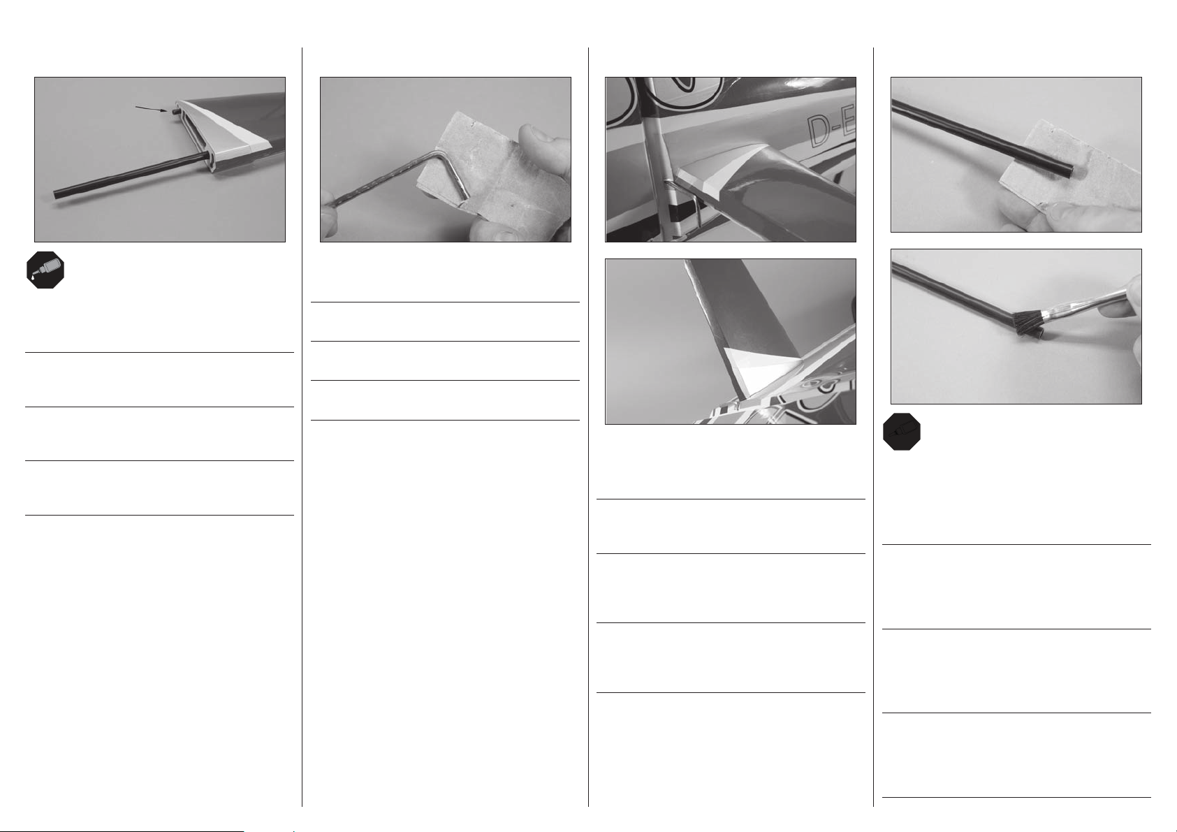
Slide the aluminum stabilizer joiner rod into the pocket in the
stabilizer. Use a small amount of CA to glue the anti-rotation
pins in the stabilizers at this time.
Schieben Sie den Höhenleitwerksverbinder in das
Leitwerk. Kleben Sie die Verdrehsicherungspins mit etwas
Sekundenkleber fest.
Glissez la clé de stabilisateur dans le fourreau. Utilisez
de la colle CA pour fi xer les pions d’anti-rotation dans les
stabilisateurs.
Inserire la baionetta in alluminio nella sua sede sullo
stabilizzatore. Fissare sullo stabilizzatore anche il perno
antirotazione con un po’ di colla CA.
2
Use sandpaper to lightly sand the elevator joiner wire where
it will fi t into the elevators.
Schleifen Sie den Leitwerksverbinderdraht an den Stellen an
wo er in die Ruder geht.
Utilisez du papier abrasif pour dépolir les parties qui
rentrent dans les gouvernes de profondeur.
Carteggiare leggermente l’elemento di unione per la parte
che entra nei due semi elevatori.
3
Slide the elevator joiner wire into the hole at the rear of the
fuselage. Fit the stabilizers to the fuselage. They will fi t
tightly to the fuselage as shown.
Schieben Sie den Leitwerksverbinderdraht durch die Öffnung
hinten im Rumpf. Stecken Sie dann das Ruder ein müssen
sie eng an das Leitwerk passen.
Glissez la tige de jonction de stabilisateur dans le trou
situé à l’arrière du fuselage. Installez les stabilisateurs sur
le fuselage. Il doivent parfaitement s’ajuster au fuselage
comme sur l’illustration.
Inserire l’elemento di unione dei due semi elevatori nel foro
sul retro della fusoliera. Adattare i due semi stabilizzatori
alla fusoliera in modo che aderiscano perfettamente, come si
vede nella fi gura.
4
30
Remove the stabilizers from the fuselage. Remove the
stabilizer tube and lightly sand the outside of the tube. Use a
paper towel and isopropyl alcohol to remove any oil or debris
from the tubes. Apply a thin coat of epoxy to the outside of
both stabilizer tubes.
Entfernen Sie das Höhenleitwerk vom Rumpf. Nehmen Sie
den Verbinder heraus und schleifen die Außenseite etwas
an. Entfernen Sie mit Papiertuch und Reinigungsalkohol
Verschmutzungen oder Öl. Streichen Sie eine dünne Schicht
Epoxy auf die Aussenseite beider Verbinder.
Retirez les stabilisateurs du fuselage. Retirez la clé et
dépolissez légèrement sa surface extérieure. Utilisez du
papier absorbant et de l’alcool isopropylique pour nettoyer le
tube. Appliquez une fi ne couche de colle époxy sur l’extérieur
sur la clé de stabilisateur.
Togliere lo stabilizzatore dalla fusoliera. Togliere il tubo e
carteggiarlo leggermente all’esterno. Con un fazzoletto di
carta e alcool isopropilico, togliere tutti i residui di olio e di
sporco dalla sua superfi cie. Applicare un leggero strato di
colla epoxy all’esterno dei due tubi.
21
Page 22
LRL
R
LRL
R
5
6
ELEVATOR INSTALLATION•MONTAGE DES HÖHENRUDERS•
INSTALLATION DES GOUVERNES DE PROFONDEUR•INSTALLAZIONE DELL’ELEVATORE
1
2
30
Apply a small amount of epoxy in the pocket of each
stabilizer half.
Geben Sie eine kleine Menge Epoxy in die Aufnahme jedes
Höhenruders.
Appliquez de la colle epoxy dans le fourreau de chaque demistabilisateur.
Applicare un po’ di colla epoxy all’interno delle sedi sulle due
metà dello stabilizzatore.
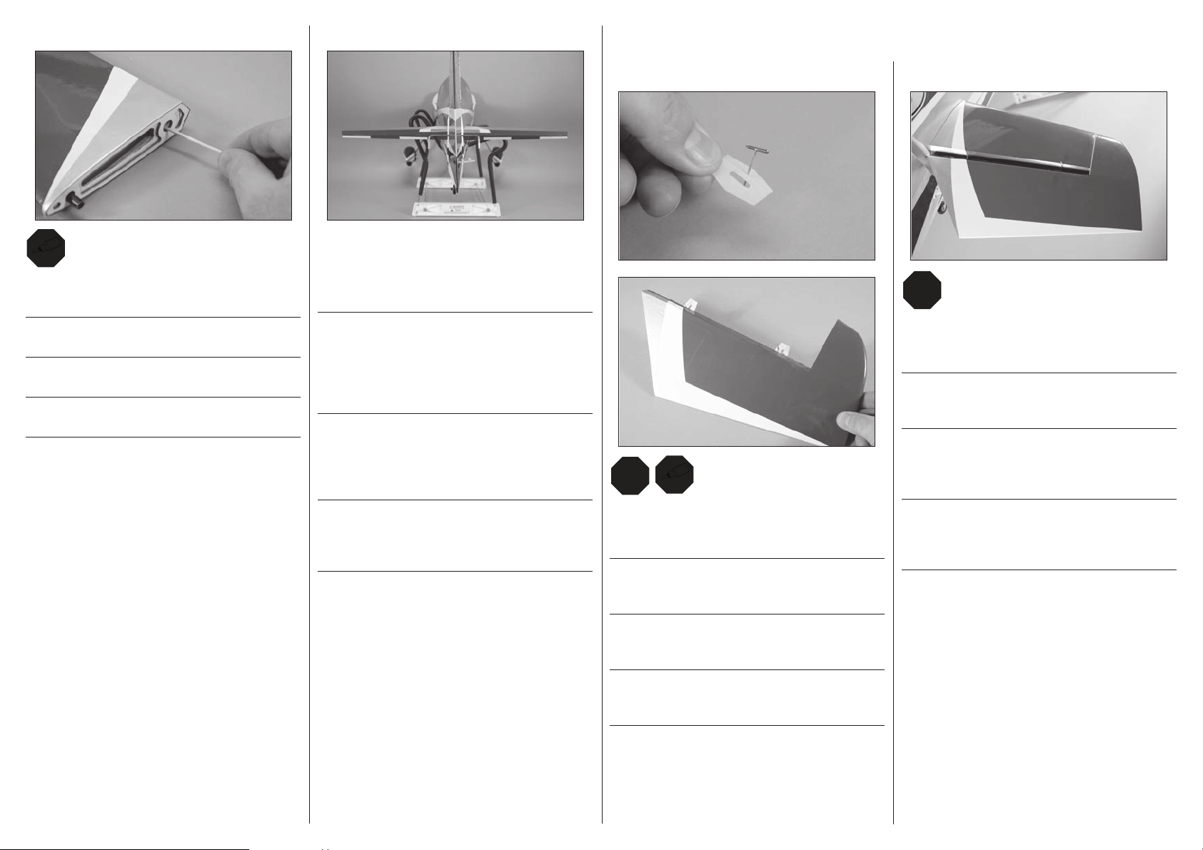
Slide the stabilizers and stabilizer tube back into position.
Stand back from the fuselage and check to make sure the
stabilizers are square to the rudder. Use low-tack tape to
hold the stabilizers in position until the epoxy fully cures.
Schieben Sie das Höhenleitwerk mit den Verbindern wieder
auf den Rumpf in Position. Treten Sie etwas zurück und
prüfen dass das Höhenleitwerk im rechten Winkel zum
Seitenleitwerk ist. Sichern Sie das Höhenruder mit Klebeband
mit geringer Klebekraft bis das Epoxy vollständig getrocknet
ist.
Replacez la clé et les demi-stabilisateurs en place.
Placez-vous derrière le fuselage pour contrôler que les demistabilisateurs sont bien perpendiculaires à la dérive. Utilisez
de l’adhésif de masquage pour maintenir les stabilisateurs
en place durant le séchage de la colle époxy.
Rimettere in posizione i tubi e lo stabilizzatore. Guardando
da dietro, controllare che gli stabilizzatori siano in squadra
con il timone. Usare nastro a bassa adesività per tenere lo
stabilizzatore in posizione fi nché la colla non asciuga.
x4
Place a T-pin in the center of the hinge. Slide the hinges
into position with the T-pin resting against the edge of the
control surface.
Stecken Sie eine T-Nadel in die Mitte jedes Scharnieres.
Schieben Sie die Scharniere in Position mit den T-Nadeln bis
zum Anschlag ein.
Insérez une épingle en “T” au milieu de chaque charnière.
Glissez les charnières en position en plaquant l’épingle
contre l’arrête de la gouverne.
Fit the elevator into position, checking that the joiner wire
allows the stabilizer to be positioned to close the hinge gap
between the elevator and stabilizer.
Schieben Sie das Höhenruder in Position und prüfen dass
mit dem Verbinderbügel die Lücke zwischen Ruderblatt und
Leitwerk schließt.
Monter la gouverne de profondeur en position, en vérifi ant
que la tige de jonction permet de positionner le stabilisateur
pour combler l’écart de charnière entre ce dernier et la
gouverne.
Inserire in posizione l’elevatore, verifi cando che il cavo di
giunzione consenta di posizionare lo stabilizzatore in modo
da chiudere lo spazio della cerniera tra l’elevatore e lo
stabilizzatore.
Mettere uno spillo con testa a T al centro delle cerniere,
inserendole in posizione fi nché lo spillo si appoggia al bordo
della superfi cie mobile.
22
Page 23
LRL
R
LRL
R
LRL
R
LRL
R
3
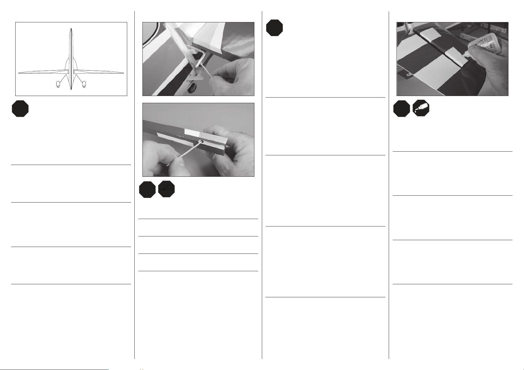
Stand back 8–10 feet (2–3 meters) and view the elevators
from the rear of the fuselage. Check to make sure the right
and left elevators are in alignment. If not, remove the
elevators and joiner wire. Bend the joiner wire as necessary
to align the elevators. Once aligned, remove the elevators
from the fuselage.
Treten Sie 2 -3 Meter zurück und prüfen ob beide Höhenruder
auf einer Linie liegen. Falls nicht entfernen Sie die
Höhenruder und den Verbinderdraht. Biegen Sie den Draht
wie notwendig um die beiden Ruder auszurichten. Einmal
ausgerichtet nehmen sie die Höhenruder vom Rumpf ab.
Placez-vous derrière le fuselage à une distance de 2 ou
3m. Contrôlez que la gouverne de profondeur gauche est
bien alignée avec la droite. Si ce n’est pas le cas, retirez
les gouvernes et la tige de jonction. Pliez la tige de façon
à obtenir l’alignement des deux gouvernes. Une fois que
l’alignement est correct, veuillez retirer les gouvernes.
Stando 2 o 3 metri dietro al modello e guardando gli
elevatori, verifi care che i due elevatori siano allineati. In
caso contrario smontarli e piegare l’elemento di unione
quanto basta. Quando sono allineati, togliere gli elevatori
dalla fusoliera.
4
30
Apply epoxy to the joiner wire and stabilizer where they
contact each other.
Streichen Sie die Kontaktstellen des Bügels und Ruder mit
Epoxy ein.
Appliquer de la colle époxy sur la tige de jonction et sur le
stabilisateur à leur point de contact.
Applicare la resina epossidica al cavo di giunzione e allo
stabilizzatore nei punti in cui essi si toccano.
5
Wrap a piece of low-tack tape around the stabilizer in the
area of the joiner wire to help prevent gluing the joiner wire
to the stabilizer. Fit the elevators into position, guiding the
joiner wire into the stabilizers. Remove the T-pins so the
gap between the stabilizer and elevators can be minimized.
Center the elevator so the gap between the stabilizer and
elevators at the tips are equal. Once the epoxy has fully
cured, remove the tape and proceed to the next step.
Wickeln Sie Klebeband mit geringer Klebekraft um das Ruder
um zu verhindern dass sich der Bügel am Leitwerk verklebt.
Nehmen Sie die T-Nadeln aus den Scharnieren heraus,
so dass Sie den Spalt zwischen Leitwerk und Ruderblatt
verkleinern können. Zentrieren Sie das Ruderblatt dass
der Abstand an den Spitzen gleich ist. Entfernen Sie das
Klebeband nach dem Kleber vollständig getrocknet ist und
machen mit dem nächsten Schritt weiter.
Enrouler un morceau d’adhésif de masquage autour du
stabilisateur dans la zone de la tige de jonction pour éviter
que cette dernière ne colle au stabilisateur. Placer les
gouvernes en position, en guidant la tige de jonction dans
les stabilisateurs. Retirer les épingles en T de sorte que
l’écart entre le stabilisateur et les gouvernes puisse être
réduit. Centrer la gouverne afi n que l’écart au sommet entre
le stabilisateur et les gouvernes soit équivalent. Une fois
que la colle époxy a complètement durci, retirer l’adhésif et
passer à l’étape suivante.
Avvolgere un pezzo di nastro a bassa aderenza attorno allo
stabilizzatore, nell’area del cavo di giunzione, per evitare
di incollare il cavo stesso allo stabilizzatore. Mettere in
posizione gli elevatori, guidando il cavo di giunzione negli
stabilizzatori. Rimuovere i perni a T in modo da ridurre al
mimino lo spazio tra lo stabilizzatore e gli elevatori. Centrare
l’elevatore in modo che lo spazio tra lo stabilizzatore e
l’elevatore in corrispondenza delle punte sia uguale. Una
volta completamente essiccata la resina epossidica,
rimuovere il nastro e passare al passaggio successivo.
6
Apply thin CA to the top and bottom of each hinge. Once the
CA cures, gently pull on the fi xed surface and control surface
to make sure the hinges are glued securely. If not, apply
additional CA to secure each of the hinges.
Tragen Sie oben und unten an jedem Scharnier eine dünne
Linie Sekundenkleber auf. Wenn der Klebstoff ausgehärtet
ist, ziehen Sie vorsichtig am Ruder und Ruderblatt um
sicherzustellen, dass die Scharniere fest angeklebt sind. Ist
dies nicht der Fall, tragen Sie noch etwas Sekundenkleber
auf, um die Scharniere zu befestigen.
Appliquer de la colle cyano fi ne sur le dessus et le dessous
de chaque charnière. Une fois la colle cyano sèche, tirer
doucement sur la surface fi xe et la gouverne pour vérifi er si
les charnières sont solidement collées. Si ce n’est pas le cas,
appliquer davantage de colle cyano pour assurer la fi xation
des charnières.
Applicare uno strato sottile di colla CA nella parte alta e in
quella bassa di ciascuna cerniera. Una volta che la colla CA
si sarà seccata, sollevare delicatamente la superfi cie fi ssa e
la superfi cie di controllo per accertarsi che le cerniere siano
saldamente incollate. Se non lo sono, applicare altra colla
CA per bloccare entrambe le cerniere.
23
Page 24

ELEVATOR LINKAGE INSTALLATION•MONTAGE DES HÖHENRUDERGESTÄNGES•
INSTALLATION DE LA COMMANDE DE PROFONDEUR•INSTALLAZIONE DEI COMANDI ELEVATORE
1
Mount the elevator servo in the fuselage using the hardware
provided with the servo. The holes for the servo should have
been prepared at the same time as the holes for mounting
the rudder servo.
Montieren Sie das Höhenruderservo im Rumpf mit den
Schrauben aus dem Lieferumfang. Die Befestigungslöcher
sollten sollten zur gleichen Zeit wie die des Seitenruders
vorbereitet werden.
Installez le servo de profondeur dans le fuselage en utilisant
les accessoires fournis avec le servo. Les trous de fi xation
du servo ont été préparés en même temps que ceux du servo
de dérive.
Montare il servo dell’elevatore in fusoliera con le viti fornite
insieme al servo. I fori per il fi ssaggio dovrebbero essere fatti
insieme a quelli per il servo del timone.
2
Insert the Z-bend of the 281/2-inch (725mm) pushrod in
servo arm to be used for the rudder. The pushrod will be 1
inch (25mm) from the center of the servo arm.
Setzen Sie das Z-gebogene Ende des 725mm Gestänges in
das Loch des Servoarms ein der 25mm von der Mitte entfernt
ist.
Utilisez un porte-foret et un foret de 2mm pour agrandir le
trou du bras de servo se situant à une distance de 25mm
du centre. Insérez la partie en “Z” de la tringlerie (725mm)
dans le trou du bras de servo.
Inserire la piegatura a Z della barretta da 725mm nel foro
che si trova a 25mm dal centro sulla squadretta del servo.
Slide the elevator pushrod into the pushrod tube. Use the
radio system to center the elevator servo. Attach the servo
arm to the servo so it is perpendicular to the servo center
line.
Schieben Sie das Höhenrudergestänge in das Röhrchen.
Zentrieren Sie mit der Fernsteuerung das Servo und setzen
den Servoarm rechtwinklig auf.
Glissez la tringlerie de profondeur dans la gaine. Utilisez la
radio pour mettre le servo au neutre. Fixez le bras de servo
au servo en le plaçant à la perpendiculaire de celui-ci.
Inserire la barretta nel suo tubetto. Centrare il servo
con il radiocomando in modo che la sua squadretta sia
perpendicolare rispetto alla linea centrale.
3
4
N
x2
Slide a silicone retainer over the clevis. Thread the clevis
on the pushrod. With the elevator servo plugged into the
receiver, adjust the clevis so the elevator is centered when
the clevis is attached to the inner hole of the elevator control
horn. Once attached, slide the retainer over the forks of the
clevis to keep it from opening accidentally.
Schieben Sie den Silikonschlauch auf den Gabelkopf.
Drehen Sie den Gabelkopf auf das Gestänge. Justieren Sie
den Gabelkopf so, dass das Ruder zentriert ist wenn der
Gabelkopf in das innere Loch des Ruderhorns gesteckt ist.
Schieben Sie nach dem Anschluss den Silikonschlauch zur
Sicherung über den Gabelkopf.
Glissez un morceau de durite silicone sur la chape. Vissez
la chape sur la tringlerie. Avec le servo relié au récepteur,
mettez votre système radio sous tension et placez le servo
au neutre. Ajustez la longueur de la tringlerie en tournant la
chape de façon à centrer les gouvernes de profondeur quand
la chape est insérée dans le trou intérieur du guignol. Une
fois que la chape est reliée au guignol, glissez le morceau de
tube silicone sur les fourches de la chape pour empêcher son
ouverture accidentelle.
x2
24
Infi lare un tubetto in silicone sulla forcella, avvitandola alla
barretta. Con il connettore del servo elevatore collegato al
ricevitore, accendere il radiocomando per centrarlo. Regolare
la posizione della forcella per centrare il timone, inserendola
nel foro più interno della squadretta collegata all’elevatore.
Fatto questo, riportare il tubetto in silicone sulla forcella per
evitare che si apra accidentalmente.
Page 25
x4
GLOW ENGINE INSTALLATION•GLÜHZÜNDEREINBAU•INSTALLATION DU MOTEUR MÉTHANOL•INSTALLAZIONE DEL MOTORE GLOW
1
2
3
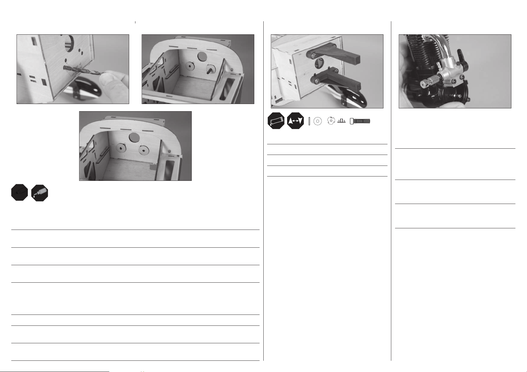
Insert a 7/32-inch (5.5mm) drill bit through the hole in the fi rewall. Slide the plywood blind nut spacers onto the drill bit. This
will align the spacers perfectly with the hole in the fi rewall. Make sure to glue the spacers in the correct location on the back
of the fi rewall.
Stecken Sie einen 5,5mm Bohrer durch das Loch im Motorspant. Schieben Sie die Sperrholzdistanzstücke auf den Bohrer, das
richtet sie perfekt aus. Achten Sie bei dem Einkleben der Distanzstücke dass diese am Spant korrekt positioniert sind.
Glissez un foret de 5.5 dans les trous de la cloison pare feu. Glissez les entretoises en contreplaqué des écrous prisonniers sur
le foret. Cela permet d’aligner parfaitement les entretoises avec les trous.
Inserire una punta da 5,5mm nel foro sull’ordinata parafi amma. Infi lare sulla punta una rondella di compensato che sarà così
allineata con il foro. Incollare i distanziali al loro posto sul retro dell’ordinata.
#8
Secure the engine mount rails to the fi rewall.
Schrauben Sie den Motorhalter an den Motorspant.
Fixer les rails de support moteur à la cloison pare-feu.
Fissare i supporti del motore alla paratia parafi amma.
8-32
x4
x4
8-32 x 1 inch
x4
Check the orientation of the carburetor in relationship to
the engine. It may be necessary to reposition the carburetor
and/or throttle arm so the engine can be installed on this
particular aircraft.
Überprüfen Sie bitte die Anbaurichtung des Vegasers. Es
könnte notwendig sein den Vergaser und oder Gashebel neu
zu positionieren, so dass dieser Motor an diesem Flugzeugtyp
eingebaut werden kann.
Contrôlez l’orientation du carburateur en fonction du moteur.
Il sera peut être nécessaire de repositionner le carburateur
et/ou le levier de gaz pour installer le moteur sur cet avion.
Controllare l’orientamento del carburatore rispetto al motore.
Potrebbe servire un riposizionamento del carburatore e/o
della squadretta dell’acceleratore.
Î Engine locations provided suit Evolution .61, 15cc, and Saito .91, 1.15, 1.25.
Other engines will require adjustment to the mounting locations.
ÎTrägerbohrungen passend für Evolution .61, 15cc und Saito .91,1.15, 1,25. Andere Motoren erfordern Anpassungen.
ÎLes trous pré-percés sont prévus pour les moteurs Evolution .61, 15cc et les moteurs Saito .91,
1.15, 1.25. Les autres moteurs nécessitent une adaptation de l’emplacement des fixations.
ÎIl posizionamento del motore è riferito all’Evolution .61, al 15cc e ai Saito .91, 1.15,
1.25. Altri tipi di motori potrebbero richiedere un posizionamento diverso.
25
Page 26
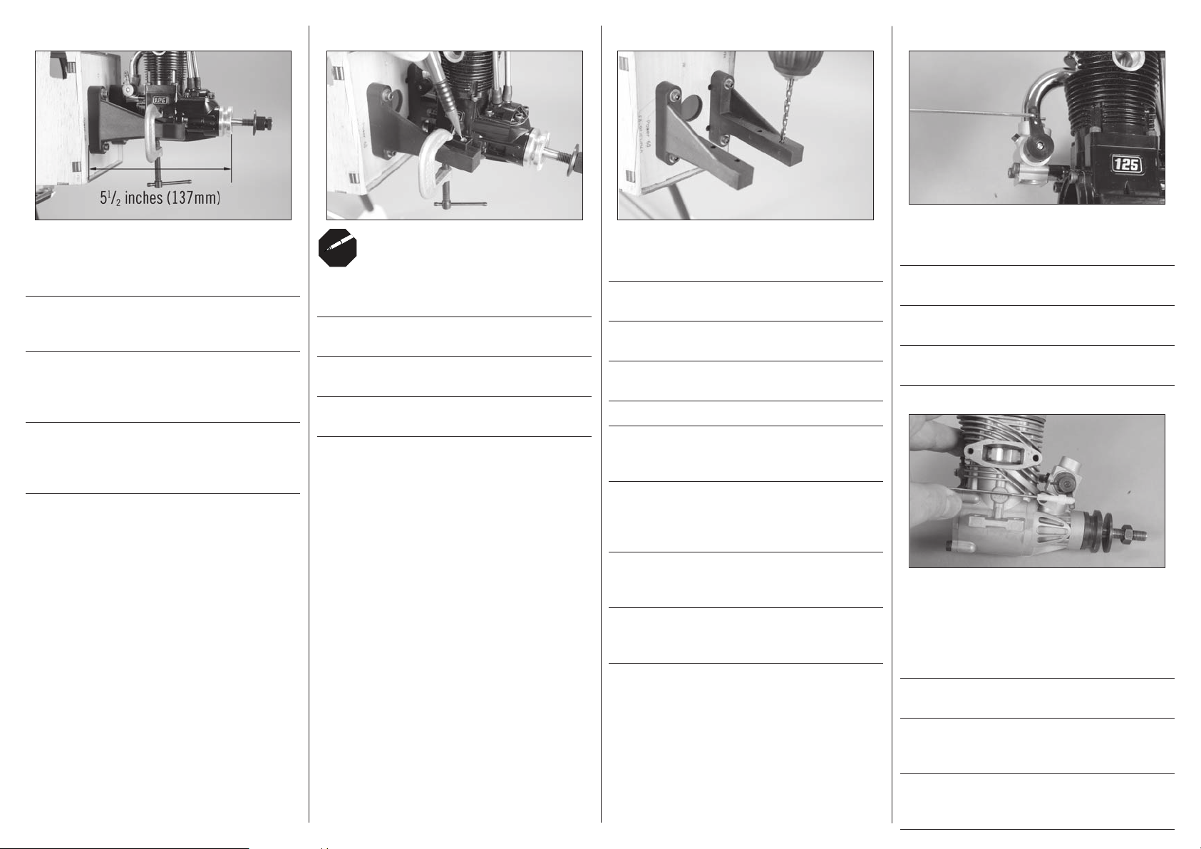
4
Position the engine so the drive washer is 51/2 inches
(137mm) forward of the fi rewall. Use a small clamp to hold
the engine in position for the following step.
Plazieren Sie den Motor so, dass der Mitnehmer 137mm vom
Motorspant entfernt ist. Fixieren Sie den Motor mit einer
Klemme für den nächsten Schritt.
Positionnez le moteur de façon à avoir une distance de
137mm entre la cloison pare-feu et le plateau d’hélice.
Utilisez un petit serre joint pour maintenir le moteur en place
pour effectuer les étapes suivantes.
Posizionare il motore in modo che la sua rondella di
trascinamento si trovi a 137mm davanti all’ordinata. Usare
un morsetto per tenere il motore in posizione per i passi
seguenti.
5
Mark the locations for the engine mounting bolts on the
engine mounting rails.
Markieren Sie die Positionen für die
Motorbefestigungsschrauben am Motorhalter
Marquer l’emplacement des boulons de fi xation du moteur
sur les supports.
Segnare le posizioni dei bulloni di montaggio del motore sui
supporti di montaggio del motore.
6
Use a drill and 5/32-inch (4mm) drill bit to drill the holes for
the engine mounting bolts.
Bohren Sie mit einem 4-mm-Bohrer Löcher für die
Motorbefestigungsschrauben.
Utiliser une perceuse et un foret de 4 mm pour percer les
trous destinés aux boulons de fi xation du moteur.
Usare un trapano con punta da 4 mm per eseguire i fori per i
bulloni di montaggio del motore.
ÎWe recommend removing the mounts from the
fuselage and using a drill press to drill the holes,
so they are aligned square to the mounting rails.
ÎEs wird empfohlen, die Halter vom Rumpf zu
entfernen und die Löcher mit einer Standbohrmaschine
zu bohren, damit sie rechtwinklig zu den
Befestigungsschienen ausgerichtet sind.
7
Connect the throttle pushrod to the throttle arm in the center
hole as shown in the photo.
Schließen Sie das Gasgestänge an dem mittlerem Loch des
Gashebels wie abgebildet an.
Connectez la tringlerie de gaz dans le trou central du levier
de gaz comme sur la photo.
Collegare il comando dell’acceleratore al foro centrale della
squadretta, come si vede nella foto.
26
ÎIl est recommandé de retirer les supports du fuselage
et d’utiliser une perceuse à colonne pour percer des
trous bien perpendiculaires aux rails de montage.
ÎSi consiglia di rimuovere i supporti dalla fusoliera e di
usare un trapano a colonna per eseguire i fori, in modo che
siano allineati in perpendicolare ai supporti di montaggio.
Î The connection of the clevis to the carburetor
arm for the 2-stroke is shown as a reference for
those installing the 2-stroke engine option.
ÎDer Anschluss des Gabelkopfes an den 2
Takt Motor ist hier als Beispiel abgebildet.
ÎLa liaison de la chape avec le levier de
gaz du moteur 2 temps est présentée comme
installation typique d’un moteur 2 temps.
ÎIl collegamento della forcella alla squadretta del
carburatore per i motori a 2 tempi, viene mostrata come
riferimento per chi volesse montare quel tipo di motore.
Page 27
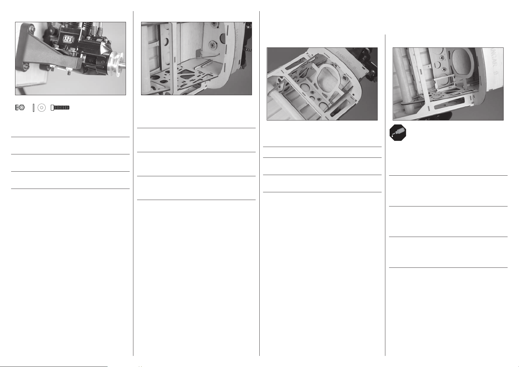
#8
x4
8
9
FUEL TANK AND THROTTLE SERVO INSTALLATION•EINBAU DES
KRAFTSTOFFTANKS UND GASSERVO•INSTALLATION DU RÉSERVOIR ET DU SERVO•
INSTALLAZIONE SERBATOIO E SERVO MOTORE
1
2
8-32
x4
Slide the pushrod through the hole in the fi rewall. Secure the
engine to the engine mount.
Schieben Sie das Gestänge durch das Loch im Motorspant.
Schrauben Sie den Motor an den Motorhalter.
Glissez la tringlerie au travers du trou de la cloison pare-feu.
Fixez le moteur à son support.
Inserire la barretta attraverso il foro nell’ordinata. Fissare il
motore al suo supporto.
8-32 x 11/4 inch
x4
Bend the throttle pushrod so it will align with the throttle
servo when it is installed. Make sure the pushrod can still
move without any binding.
Biegen Sie das Gasgestänge so, dass es mit dem montiertem
Servo ausgerichtet ist. Achten Sie bitte dabei darauf dass
sich das Gestänge dabei noch ungehindert bewegen kann.
Coudez la tringlerie de façon à l’aligner par rapport à
l’emplacement où sera installé le servo de gaz. Contrôlez que
la tringlerie peut librement coulisser sans risque de blocage.
Piegare il comando del motore in modo da allinearlo con il
suo servo, quando sarà installato. Verifi care che il comando
si muova liberamente.
Fit the fuel tank former in the fuselage. Do not glue the
former at this time.
Setzen Sie den Tankhalter in den Rumpf ein.
Positionnez le couple du réservoir dans le fuselage. Ne le
collez pas maintenant.
Montare in fusoliera il supporto del serbatoio, senza
incollarlo.
Test fi t the throttle servo tray in the fuselage. Check the
alignment of the throttle pushrod, making sure it is bent so
it is slightly above the tray. Glue the throttle servo tray in the
fuselage.
Prüfen Sie die Passung des Gasservos im Rumpf. Prüfen Sie
die Ausrichtung des Gasgestänges und stellen sicher dass
dieser etwas überhalb des Trägers gebogen ist. Kleben Sie
dann den Halter im Rumpf ein.
Effectuez un montage à blanc du support de servo dans le
fuselage. Contrôlez l’alignement avec la tringlerie des gaz,
elle doit être légèrement au-dessus du support. Collez le
support à l’intérieur du fuselage.
Provare a inserire il portaservo in fusoliera. Verifi care
l’allineamento del comando motore, accertandosi che sia
piegato per passare appena sopra al portaservo. Incollare il
portaservo in fusoliera.
27
Page 28
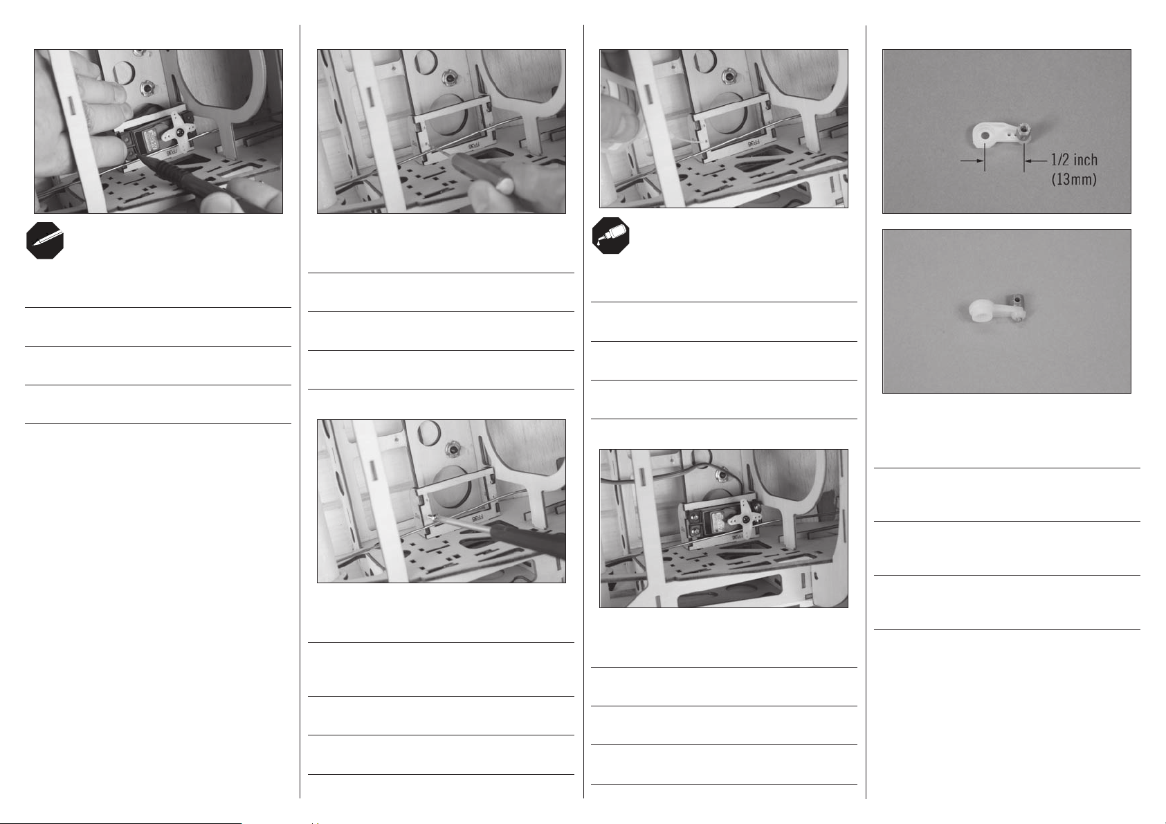
3
Place the throttle servo into position. Mark the location for
the servo mounting screws.
Setzen Sie das Gasservo in Position. Markieren Sie die Punkte
für die Servobefestigunggschrauben .
Placez le servo en position. Marquez l’emplacement des vis
de fi xation.
Posizionare il servo del motore. Segnare la posizione delle
sue viti di fi ssaggio.
4
Use a pin vise and 5/64-inch (2mm) drill bit to drill the holes
for the servo mounting screws.
Bohren Sie mithilfe eines Feilklobens und eines 2-mmBohrers die Löcher für die Servo-Befestigungsschrauben.
Utiliser un porte-foret et un foret de 2 mm pour percer les
trous destinés aux vis de fi xation du servo.
Usare una morsa stretta e una punta per trapano da 2 mm
per fare i fori per le viti di montaggio del servo.
5
6
Apply a small amount of thin CA to harden the threads made
in the previous step.
Geben Sie einen kleinen Tropfen dünnfl üssigen
Sekundenkleber in die Gewindelöcher um diese zu härten.
Appliquer une petite quantité de colle cyano fi ne pour durcir
les fi letages faits lors de l’étape précédente.
Mettere una piccola quantità di colla CA nei fori, per indurire
il fi letto fatto nel passaggio precedente.
7
8
Secure the brass pushrod connector to the throttle servo arm.
Remove any arms that may interfere with the operation of
the throttle servo.
28
Thread a servo mounting screw into each hole to cut threads
in the surrounding wood.
Drehen Sie in jede Bohrung eine ServoBefestigungsschraube, um ein Gewinde in das Holz zu
schneiden.
Visser une vis de fi xation de servo dans chaque trou pour
créer un fi letage dans le bois.
Avvitare una vite per il montaggio dei servo in ciascun foro
per eseguire dei fi letti nel legno circostante.
Schrauben Sie den Gestängeanschlus auf das Ruderhorn.
Entfernen Sie alle weitere Servoarme die den Betrieb
behindern könnten.
Fixez le connecteur de tringlerie sur le bras de servo des gaz.
Retirez les bras pouvant interférer dans le mouvement du
servo des gaz.
Fissare il nottolino di ottone sulla squadretta del servo.
Togliere gli altri bracci della squadretta in modo che non
interferiscano con i movimenti.
Secure the throttle servo in the fuselage using the screws
provided with the servo.
Schrauben Sie das Gasservo mit den Schrauben aus dem
Lieferumfang fest.
Fixez le servo des gaz dans le fuselage en utilisant les vis
fournies avec le servo.
Fissare il servo del motore in fusoliera usando le viti fornite
con il servo stesso.
Page 29
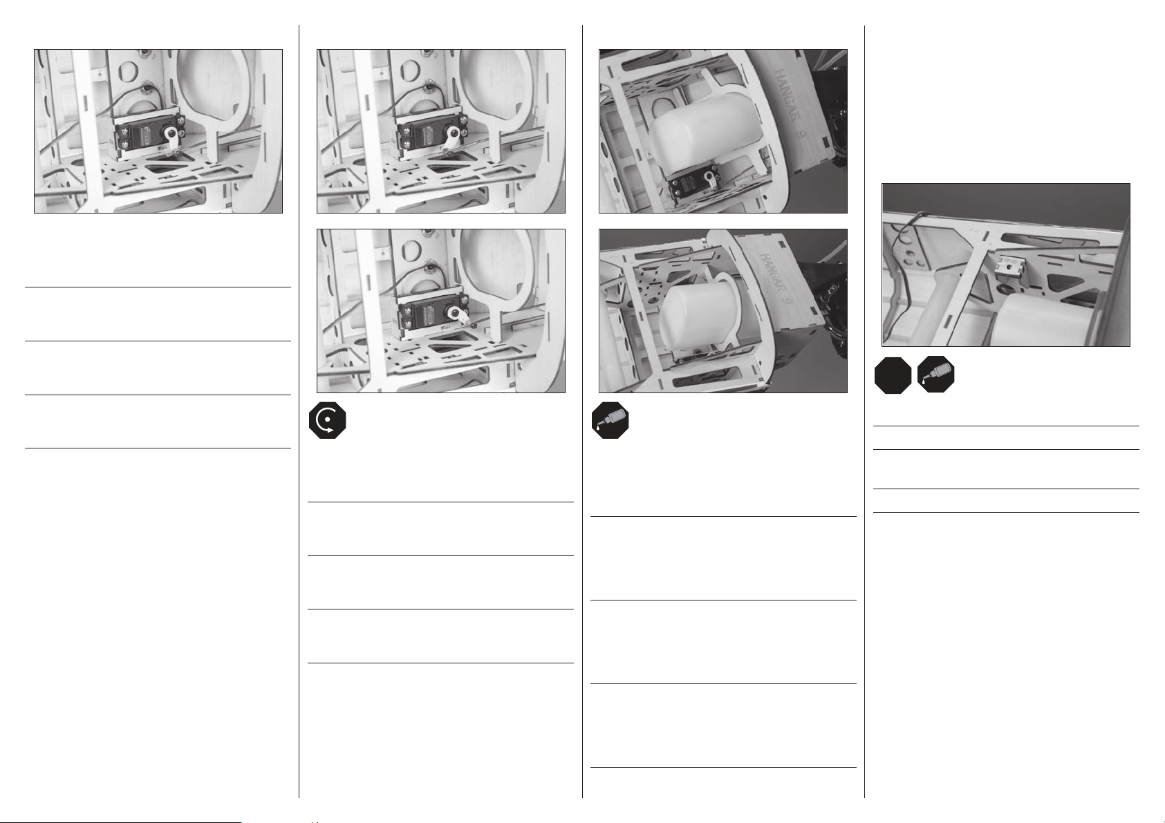
LRL
R
9
Slide the connector over the pushrod wire. Center the throttle
stick and trim, then attach the arm perpendicular to the
servo center line.
Schieben Sie den Gestängeanschluß über den Draht.
Zentrieren Sie den Gashebel und Trimmung und setzen den
Servoarm rechtwinklig auf den Servo auf.
Faire glisser le connecteur sur le fi l de tringlerie.
Centrer la manette et le trim des gaz, puis fi xer le bras
perpendiculairement à la ligne médiane du servo.
Far scorrere il connettore al di sopra del rinvio di comando.
Centrare la barra del throttle e il trim, poi fi ssare il braccio
perpendicolarmente alla linea centrale del servo.
10
Check the operation of the carburetor using the radio system.
Make any adjustments necessary so the throttle operates
without binding.
Überprüfen Sie den Betrieb des Vergasers mit der
Fernsteueranlage. Nehmen Sie etwaige Einstellungen vor,
damit die Drossel funktionert, ohne sich festzulaufen.
Vérifi er le fonctionnement du carburateur à l’aide du
système radio. Procéder aux réglages nécessaires afi n que la
commande des gaz fonctionne librement.
Verifi care il funzionamento del carburatore usando il
radiocomando. Eseguire le eventuali regolazioni necessarie
affi nché il throttle funzioni senza impedimenti.
11
The fuel tank former will have to be moved in order to install
the fuel tank. The neck of the tank will fi t into the hole in the
fi rewall. Once fi t, move the former back into position and
glue using medium CA.
Um den Tank einzubauen müssen Sie den Halter bewegen.
Der Hals des Tanks paßt in die Öffnung im Motorspant.
Schieben Sie den Tankhalter nach dem Anpassen
wieder zurück in Position und kleben ihn mit mittlerem
Sekundenkleber ein.
Le couple du réservoir devra être déplacé pour y glisser le
réservoir. Le goulot du réservoir se glisse dans l’ouverture
de la cloison pare-feu. Une fois que le réservoir est installé,
repositionnez le couple et collez-le à l’aide de colle CA
moyenne.
RECEIVER INSTALLATION FOR GLOW
ENGINE INSTALLATION•
EMPFÄNGEREINBAU FÜR GLÜHZÜNDER•
INSTALLATION DU RÉCEPTEUR DANS LE
CAS D’UN MOTEUR MÉTHANOL•
INSTALLAZIONE DEL RICEVITORE QUANDO
SI USA UN MOTORE GLOW
1
Secure the receiver tray mounts in the fuselage.
Kleben Sie den Empfängerhalter in den Rumpf ein.
Fixez les blocs de fi xation de la platine du récepteur dans le
fuselage.
Fissare in fusoliera i supporti per il ricevitore.
Il supporto del serbatoio deve essere spostato per poterlo
installare. Il collo del serbatoio andrà a fi nire nel foro
sull’ordinata. Quando si è trovato l’adattamento, muovere
indietro il supporto e incollarlo in posizione con colla CA
media.
29
Page 30
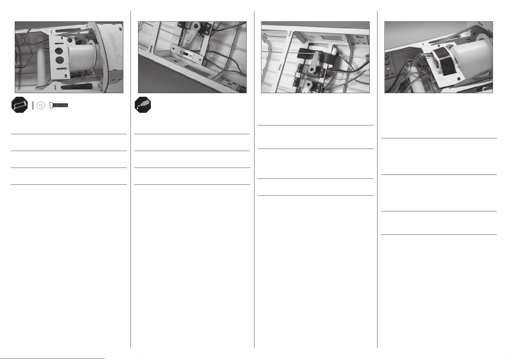
#4
x2
2
4-40 x 1/2-inch
Slide the tray into the fuselage. The tray is secured using the
hardware listed.
Schieben Sie den Halter in den Rumpf und schrauben ihn mit
den mitgelieferten Schrauben fest.
Glissez la platine dans le fuselage. La platine se fi xe en
utilisant les accessoires listés au-dessus.
Inserire il supporto nella fusoliera e fi ssarlo con le viti
elencate.
x2
3
Secure the switch in the switch mount using the hardware
provided, then glue the mount to the fuselage.
Schrauben Sie den Schalter in das Schalterbrettchen ein und
kleben dann das Brettchen in den Rumpf.
Fixez l’interrupteur dans son support en utilisant les
accessoires inclus, puis fi xez le support dans le fuselage.
Fissare l’interruttore sul suo supporto usando le viti fornite,
poi incollare il supporto alla fusoliera.
4
Secure the receiver battery in the fuselage using 1/4-inch
(6mm) foam and a hook and loop strap. Connect the lead
from the battery to the correct lead of the switch.
Befestigen Sie den Empfängerakku mit 6mm Schaumstoff
und Klettband. Schließen Sie den Akku richtig am Schalter
am.
Fixez la batterie de réception dans le fuselage en utilisant
de la mousse de 6mm d’épaisseur et une sangle autoagrippante. Connectez la prise de la batterie à la prise
appropriée de l’interrupteur.
Fissare in fusoliera la batteria dell’impianto ricevente
usando spugna da 6mm e una fascetta a strappo.
5
Use hook and loop straps and 1/4-inch (6mm) foam rubber
to secure the receiver in the fuselage. Make sure to connect
the rudder, elevator and throttle servos. The ailerons will
require the use of 6-inch (152mm) extensions to connect the
receiver to the servo leads.
Befestigen Sie den Empfänger mit Klettstreifen und
6mm Schaumstoff im Rumpf. Bitte achten Sie auf den
Anschluss von Seitenruder, Höhenruder und Gasservo.
Die Querruderanschlüsse erfolgen über 152mm
Servoverlängerungen.
Utilisez des sangles auto-agrippantes et de la mousse de
6mm d’épaisseur pour fi xer le récepteur dans le fuselage.
Connectez le servo de dérive, de profondeur et de gaz. Les
servos d’ailerons nécessitent l’utilisation de rallonges de 15
cm de long pour être raccordés au récepteur.
Collegare al ricevitore le spinette dei servi timone, elevatore
e motore. Per gli alettoni è necessaria una prolunga da
150mm.
30
Page 31
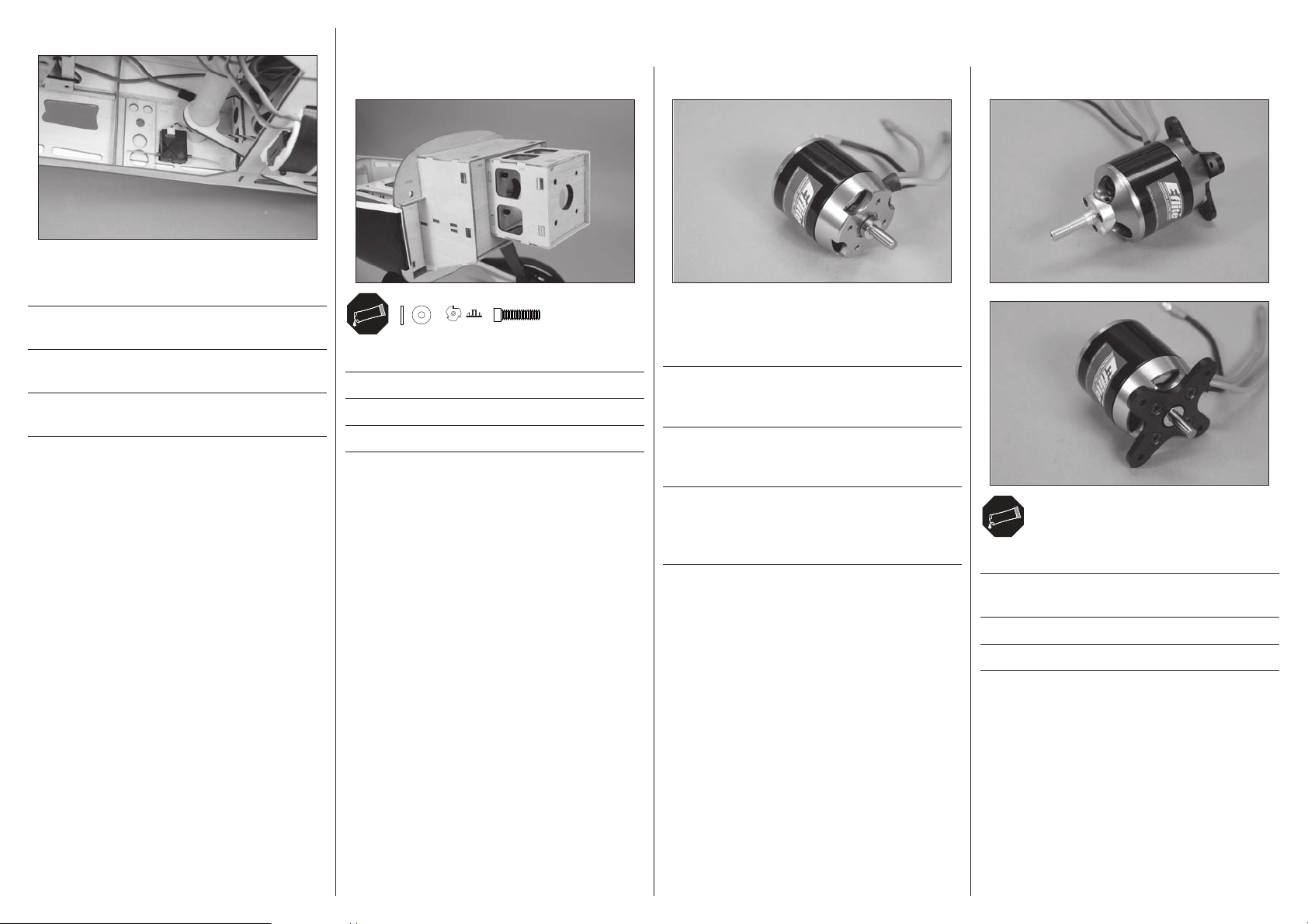
6
Mount the remote receiver in the fuselage using hook and
loop tape.
Montieren Sie den Satellitenempfänger im Rumpf mit
Klettband.
Fixez le récepteur satellite dans le fuselage à l’aide de bande
auto-agrippante.
Montare in fusoliera il ricevitore satellite usando del nastro
adesivo a strappo.
EP MOTOR INSTALLATION•EINBAU DES ELEKTRO MOTORS•
INSTALLATION DU MOTEUR ÉLECTRIQUE•INSTALLAZIONE MOTORE ELETTRICO
1
#6
6-32
x4
Attach the motor box to the fuselage.
Schrauben Sie die Motorbox an den Rumpf.
Fixer le cadre moteur au fuselage.
Fissare la scatola del motore alla fusoliera.
6-32 x 1/2-inch
x4
x4
2
The motor shaft must be repositioned to allow the
installation of the propeller adapter. Make sure not to
damage the motor when repositioning the shaft.
Für den Motoreinbau müssen Sie die Welle neu positionieren.
Bitte achten Sie darauf dabei den Motor nicht zu
beschädigen.
L’arbre du moteur doit être repositionné pour permettre
l’installation de l’adaptateur d’hélice. Veiller à ne pas
endommager le moteur lors du repositionnement de l’arbre.
3
L’albero del motore deve essere riposizionato in modo
da consentire l’installazione dell’adattatore dell’elica.
Accertarsi di non danneggiare il motore quando si
riposiziona l’albero.
Attach the propeller adapter and X-mount to the motor.
Montieren Sie den Propeller Adapter und X- Motor Träger auf
den Motor.
Fixer l’adaptateur d’hélice et le croisillon en X au moteur.
Fissare al motore l’adattatore per l’elica e il supporto a X.
31
Page 32
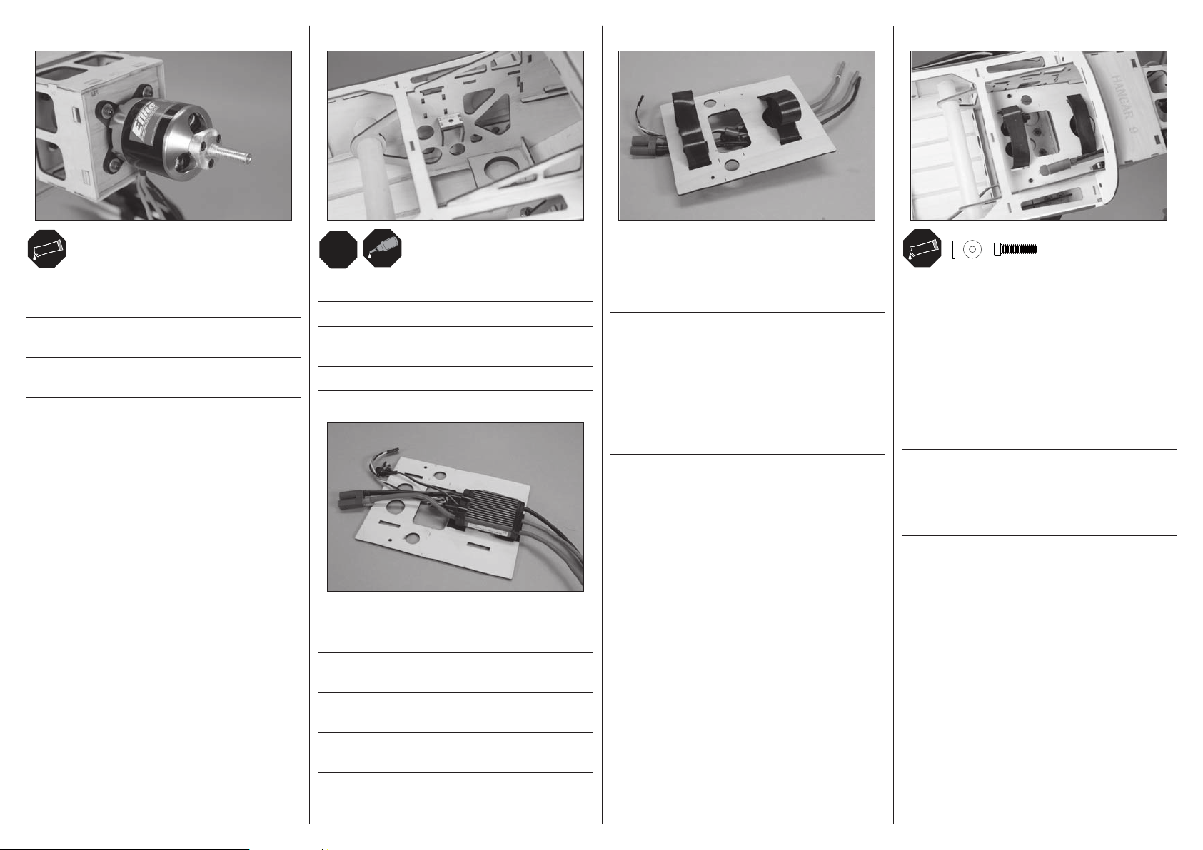
LRL
R
#4
x2
4
Secure the motor to the motor box using the hardware
included with the motor.
Sichern Sie den Motor an der Motorträgerbox mit dem im
Lieferumfang des Motors enthaltenen Befestigungen.
Fixer le moteur au bâti du moteur en utilisant le matériel
fourni avec le moteur.
Fissare il motore al suo supporto con le viti fornite insieme
al motore.
5
Secure the battery tray mounts in the fuselage.
Kleben Sie den Spant des Akkuhalters in den Rumpf ein.
Fixez les blocs de fi xation de la platine de la batterie dans le
fuselage.
Fissare in fusoliera i supporti per la batteria del motore.
6
7
Place the hook and loop straps in position in the battery tray.
The front strap will go around the speed control to help keep
in position. The rear strap must not interfere with the wiring
from the speed control.
Führen Sie die Klettschlaufe durch den Halter. Die vordere
Schlaufe geht um den Regler und sichert ihn mit . Die
hintere Schlaufe darf nicht über die Reglerkabel geführt
werden.
Placez les sangles auto-agrippantes dans la platine. La
sangle avant entourer le contrôleur pour le maintenir en
position. La sangle arrière ne doit pas serrer les câbles du
contrôleur.
Mettere in posizione le fascette a strappo per la batteria. La
fascetta anteriore passerà intorno al regolatore di velocità
per aiutare a tenerlo in posizione. La fascetta posteriore non
deve interferire con il cablaggio uscente dal regolatore.
8
4-40 x 1/2-inch
Place the hook and loop straps through the slots in the
battery tray. Slide the tray into the fuselage, guiding the
leads for the motor though the hole in the fi rewall. The tray is
secured using the hardware listed. Mount the switch where it
can be accessed from inside the fuselage.
Setzen Sie nachdem Sie die Schlaufen gesichert haben
den Akkuhalter in den Rumpf ein und führen dabei die
Motorkabel durch die Öffnung im Rumpf. Schrauben Sie den
Halter mit den aufgeführten Schrauben fest. Montieren Sie
den Schalter an gut erreichbarer Stelle im Rumpf.
Glissez la platine dans le fuselage, guidez les câbles du
moteur au travers de la cloison pare-feu. La platine se
fi xe en utilisant les accessoires listés au-dessus. Installez
l’interrupteur où il est facilement accessible depuis
l’intérieur du fuselage.
x2
Far passare le fascette a strappo attraverso le fessure sul
supporto batteria. Inserire il supporto in fusoliera facendo
passare i fi li del motore nel foro sull’ordinata. Fissare il
supporto con le viti indicate. Montare l’interruttore in modo
che sia accessibile dall’interno della fusoliera.
Secure the speed control to the bottom of the battery tray
using hook and loop tape (not included).
Sichern Sie den Regler an der Unterseite des Akkuhalters mit
Klettband (nicht im Lieferumfang).
Fixez le contrôleur sous la platine en utilisant de la bande
auto-agrippante (non fournie).
Fissare il regolatore di velocità sotto al supporto batteria con
del nastro a strappo (non fornito).
32
Page 33
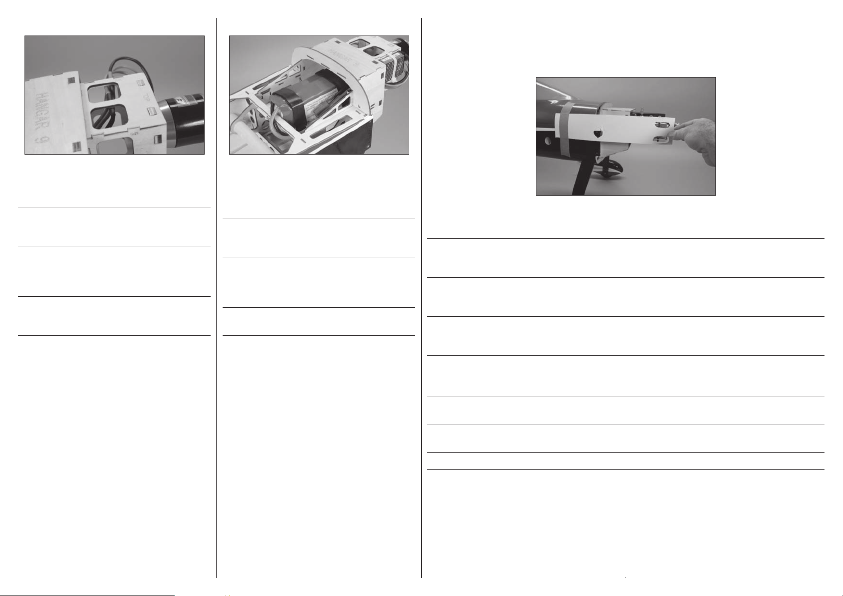
9
10
COWLING AND SPINNER INSTALLATION•MONTAGE DES SPINNER
UND DER MOTORHAUBE•INSTALLATION DU CAPOT ET DU CÔNE•
INSTALLAZIONE DI CAPOTTINA E OGIVA
1
Connect the leads from the speed control to the motor.
Secure the wiring using tie wraps (not included) so they
don’t interfere with the operation of the motor.
Schließen Sie die Reglerkabel am Motor an. Sichern Sie die
Kabel mit Kabelbindern (nicht im Lieferumfang) so dass sie
den Motorbetrieb nicht stören können.
Connectez les câbles entre le contrôleur et le moteur.
Sécurisez les câbles à l’aide de colliers en nylon (non
fournis) de façon à ne pas interférer avec le fonctionnement
du moteur.
Collegare i fi li del regolatore al motore fi ssandoli con delle
fascette (non fornite) in modo che non interferiscano con il
funzionamento del motore.
Apply hook tape to the battery and loop tape to the battery
tray, then secure the battery to the battery tray using hook
and loop straps. This will keep the battery from sliding on
the tray during fl ight.
Sichern Sie den Akku auf dem Träger und an der Unterseite
mit Klettband und führen dann die Klettschlaufe um den
Akku. Das verhindert dass sich der Akku im Flug bewegt.
Appliquez de la bande auto-agrippante entre la batterie et
le support de batterie, puis sécurisez la batterie à l’aide des
sangles auto-agrippantes. Cela empêchera la batterie de
glisser durant le vol.
Fissare la batteria al suo supporto con le fascette a strappo.
Questo eviterà che possa muoversi durante il volo.
Use card stock to locate any items that may protrude through the cowl, such as the valve covers and needle valve. Tape the
card stock to the fuselage so the items can be easily located when the cowl is placed on the fuselage.
Ermitteln Sie mit einem Stück Karton alle Gegenstände die durch die Motorhaube reichen würden wie zum Beispiel
Ventildeckel oder Ventilnadeln. Kleben Sie einen Karton an den Rumpf so das Sie einfach die Position bestimmen können wenn
die Motorhaube auf den Rumpf aufgesetzt wird.
Utilisez de la carte à découper pour déterminer les éléments qui pourraient interférer avec le capot, comme par exemple les
caches culbuteurs et le pointeau. Maintenez la carte sur le fuselage à l’aide de ruban adhésif, les éléments seront faciles à
localiser une fois le capot en place.
Usare un cartoncino per segnare tutto quello che sporge dalla capottina motore, come i coperchi delle valvole e lo spillo del
carburatore. Fissare il cartoncino alla fusoliera con nastro adesivo in modo da poter poi individuare le sporgenze quando si
mette la capottina motore al suo posto.
Î When installing the Saito™ 115, the valve covers will fit inside the cowl. Cutting the cowl will not be required.
ÎBei der Montage des Saito 115 passen die Ventildeckel unter die
Motorhaube so dass ein Ausschneiden nicht notwendig ist.
ÎDans le cas de l’installation d’un moteur Saito 115, les caches culbuteurs se
logent à l’intérieur du capot. Aucune découpe du capot est nécessaire.
ÎSe si monta un motore Saito 115, i coperchi delle valvole non sporgono e quindi non è necessario tagliare la capottina.
33
Page 34

2
Slide the cowl on the fuselage. You may not be able to install
any of the bolts depending on your engine selection. At this
time, lining up the cowl close is suffi cient.
Schieben Sie die Motorhaube auf den Rumpf. Es
kann möglich sein dass sie je nach Motorauswahl die
Befestigungsschrauben noch nicht eindrehen können.
Zu diesem Zeitpunkt reicht es wenn Sie die Motorhaube
ausrichten.
Glissez le capot sur le fuselage. En fonction du moteur
choisi, vous ne pourrez peut être pas le fi xer avec toutes les
vis. A cette étape l’alignement est suffi sant.
Infi lare la capottina sulla fusoliera. È possibile che non si
possano mettere le viti, in base al motore scelto. In questa
fase è suffi ciente appoggiarla vicino.
3
Mark the cowling for the openings.
Markieren Sie die notwendigen Öffnungen auf der
Motorhaube.
Marquez sur le capot l’emplacement des ouvertures à
effectuer.
4
When trimming the cowling, start with small openings and
slowly enlarge them to fi t the engine. Use a rotary tool with a
sanding drum to fi nish any rough edges that may occur when
using hobby scissors or a hobby knife.
Beginnen Sie mit kleinen Öffnungen und vergrößern Sie diese
langsam. Verwenden Sie einen elektrischen Drehschleifer um
scharfe Kanten abzuschleifen.
Quand vous découpez le capot, commencez par de petites
ouvertures et agrandissez-les lentement pour les ajuster
au moteur. Utilisez un outil de ponçage rotatif pour éliminer
les arrêtes vives laissées par les découpes au couteau de
modélisme.
Quando si taglia la capottina, bisogna iniziare a fare delle
aperture piccole allargandole piano piano fi no a raggiungere
la dimensione necessaria. Usare un trapanino con mola
smeriglio per rifi nire eventuali tagli non precisi.
5
Attach the muffl er to the engine. The cowling will need to be trimmed to fi t over the muffl er once it has been installed.
Connect the fuel lines to the engine and muffl er.
Montieren Sie den Schalldämpfer am Motor. Passen Sie nach der Montage die Motorhaube an und schließen die
Kraftstoffl eitungen an.
Fixez le silencieux au moteur. Le capot nécessitera une découpe autour du silencieux. Connectez les durites du circuit de
carburant au moteur et au silencieux.
Fissare il silenziatore al motore. Sarà necessario tagliare la capottina per farlo stare. Collegare anche tutti i tubetti al motore
e al silenziatore.
ÎInstall a fuel filter in the line between the carburetor and fuel tank to
prevent any debris in the fuel from entering the engine.
ÎMontieren Sie einen Kraftstoffilter zwischen Vergaser und Tank um den
Motor vor Verschmutzungen im Kraftstoff zu schützen.
ÎInstaller un filtre à carburant dans la conduite entre le réservoir de carburant et le carburateur pour
empêcher les corps étrangers éventuellement présents dans le carburant de pénétrer dans le moteur.
ÎInstallare un filtro per carburante nella linea tra il carburatore e il serbatoio del carburante,
per impedire che eventuali detriti presenti nel carburante entrino nel motore.
Segnare le aperture da fare sulla capottina.
34
Page 35
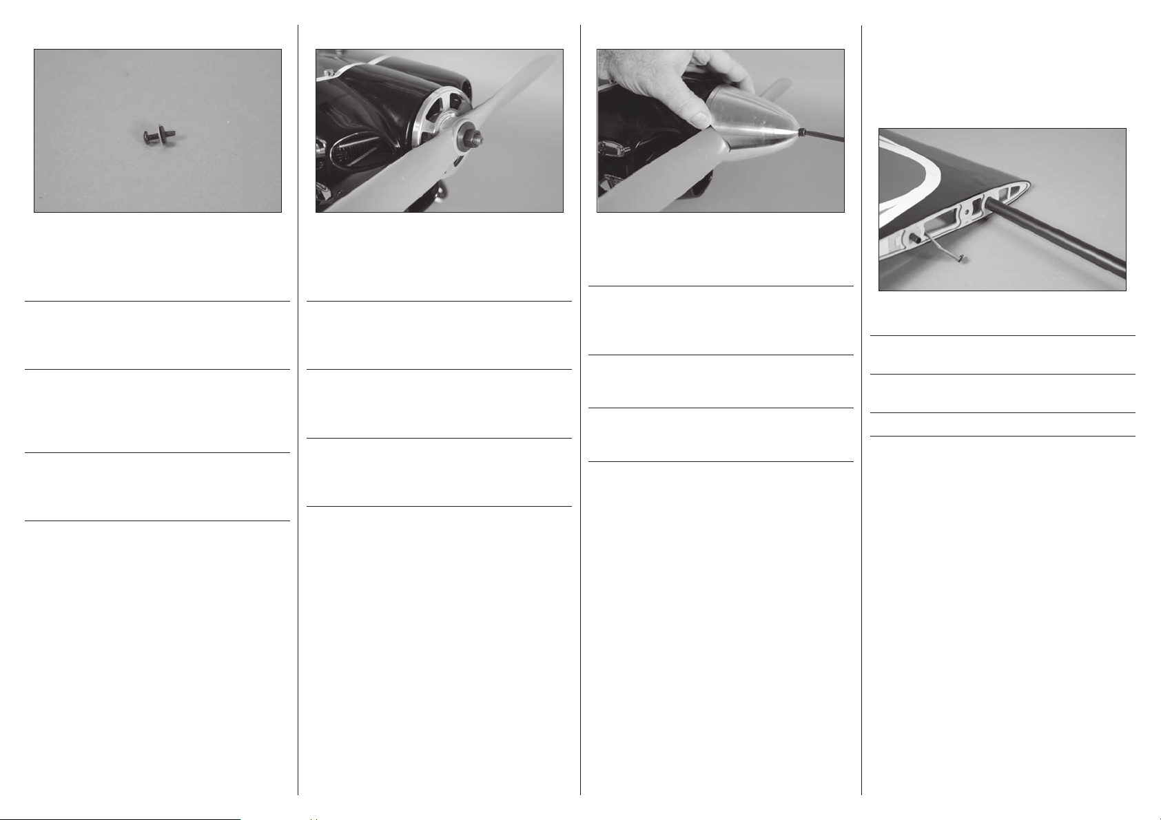
6
7
8
WING INSTALLATION•
MONTAGE DER TRAGFLÄCHEN•
INSTALLATION DE L’AILE•
MONTAGGIO DELL’ALA
1
Prepare the engine mounting bolts by sliding the tapered
washer on the bolt. Remove the backing from the foam disk,
then slide the disk (adhesive side fi rst) onto the bolt. Use the
bolts to secure the cowling to the fuselage.
Bereiten Sie die Befestigungsschrauben der Motorhaube vor.
Ziehen Sie die Rückseite von der gepolstern Unterlegscheibe
ab und setzen Sie diese auf die Schraube (klebende Seite
zuerst)
Préparez les vis de fi xation du capot moteur en y glissant une
rondelle épaulée. Retirez la protection de la partie adhésive
de la rondelle en mousse. Glissez la rondelle en mousse sur
la vis (la partie adhésive en premier). Utilisez les vis pour
fi xer le capot au fuselage.
Preparare le viti di fi ssaggio del motore infi lando le rondelle
coniche. Togliere la pellicola dai dischi in spugna, poi
infi larli (prima il lato adesivo) sulle viti. Usare le viti per
fi ssare la capottina alla fusoliera.
Install the spinner back plate and propeller. Secure the
propeller using the appropriate adapter nut suited to your
particular engine installation. Secure the spinner adapter
using a 1/2-inch wrench.
Montieren Sie die Spinnerückplatte und den Propeller.
Sichern Sie den Propeller mit dem passenden Adapter und
Mutter. Sichern Sie den Spinneradapter mit einem 1/2 inch
Maulschlüssel.
Installer le fl asque arrière de cône et l’hélice. Fixer l’hélice
à l’aide de l’écrou adaptateur adapté à votre moteur
spécifi que. Fixer l’adaptateur de cône en utilisant une clé
d’un demi-pouce.
Installare la piastra posteriore dell’ogiva e l’elica. Fissare
l’elica usando il dado adattatore idoneo allo specifi co motore
in uso. Bloccare l’adattatore dell’elica usando una chiave da
10 mm.
Secure the spinner cone to the engine. Make sure the blades
of the propeller do not contact the cone. Tighten the screw
using a hex wrench.
Sichern Sie den Spinnerkonus auf dem Motor. Stellen Sie
sicher dass die Propellerblätter nicht in Berührung mit
dem Konus kommen. Ziehen Sie die Schraube mit einem
Inbusschlüssel an.
Fixer le cône d’hélice au moteur. Veiller à ce que les pales de
l’hélice ne soient pas en contact avec le cône. Serrer la vis à
l’aide d’une clé hexagonale.
Fissare il cono dell’ogiva al motore. Accertarsi che le pale
dell’elica non tocchino il cono. Serrare la vite usando una
chiave esagonale.
Slide the wing tube into the wing tube socket.
Schieben Sie den Flächenverbinder in die Öffnung an der
Tragfl äche.
Faire glisser le tube de l’aile dans le réceptacle du tube de
l’aile.
Inserire il tubo nella sua sede nell’ala.
35
Page 36
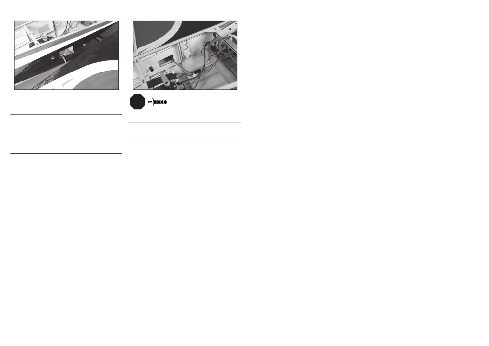
LRL
R
2
Slide the wing panel into position, guiding the extensions
from the wing into the fuselage.
Schieben Sie die Tragfl äche in die richtige Position. Führen
Sie dabei die Verlängerungen vom Flügel in den Rumpf.
Mettre en place le panneau de l’aile en le faisant glisser et
en veillant à guider les rallonges provenant de l’aile dans le
fuselage.
Far scorrere in posizione la semiala, guidando le prolunghe
dall’ala all’interno della fusoliera.
3
1/4-20 x 1.5 inch
Secure the wing panels to the fuselage.
Befestigen Sie die Tragfl ächen am Rumpf.
Fixer le panneau de l’aile au fuselage.
Fissare l’ala alla fusoliera.
x2
36
Page 37
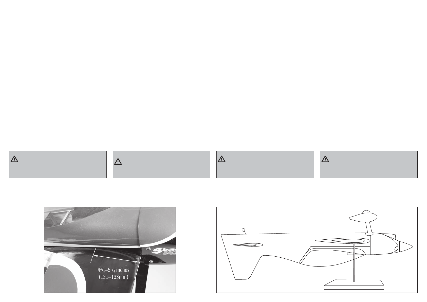
CENTER OF GRAVITY
DER SCHWERPUNKT
CENTRE DE GRAVITÉ
CENTRO DI GRAVITA’ (BARICENTRO)
An important part of preparing the aircraft for fl ight is
properly balancing the model.
1. Attach the wing panels to the fuselage. Make sure to
connect the leads from the aileron to the appropriate leads
from the receiver. Make sure the leads are not exposed
outside the fuselage before tightening the wing bolts. Your
model should be fl ight-ready before balancing.
2. The recommended Center of Gravity (CG) location for
your model is 4
leading edge of the wing at the wing root as shown. Mark the
location of the CG on the top of the wing.
3. When balancing your model, make sure it is assembled
and ready for fl ight. Using an assistant, lift the model at the
locations marked in the previous step. This is the correct
balance point for your model.
3
/4–51/4 inches (121–133mm) back from the
CAUTION: You must adjust your aircraft’s center
of gravity and balance your model properly before
attempting fl ights.
Ein sehr wichtiger Teil in der Flugvorbereitung ist es das
Flugzeug richtig auszubalancieren.
1. Montieren Sie Tragfl ächen am Rumpf. Stellen Sie sicher,
dass die Querruderservoanschlüsse in die richtigen Buchsen
am Empfänger gesteckt sind. Achten Sie darauf, dass keine
Kabel zwischen Rumpf und Fläche herausschauen. Das
Modell sollte vor dem Balancieren fl ugfertig ausgerüstet
sein.
2. Der empfohlene Schwerpunkt für Ihr Modell befi ndet
sich in 121–133mm Entfernung zur Flügelvorderkante, wie
abgebildet. Markieren Sie den Schwerpunkt an der Oberseite
des Flügels.
3. Das Modell sollte vor dem Ausbalancieren fl ugfertig
ausgerüstet sein. Heben Sie das Modell mithilfe einer
zweiten Person an den im vorherigen Schritt markierten
Stellen hoch. Dies ist der richtige Balancepunkt für Ihr
Modell.
ACHTUNG: Der Schwerpunkt muß vor dem
Erstfl ug korrekt ausbalanciert sein.
Une des étapes importantes de la préparation d’un modèle
est son équilibrage.
1. Fixez les ailes au fuselage. Vérifi ez que les ailerons sont
reliés aux prises appropriées du récepteur. Contrôlez que
les câbles ne dépassent pas du fuselage avant de serrer
les ailes. Votre modèle doit être prêt à voler pour effectuer
l’équilibrage.
2. Le centre de gravité (CG) recommandé de votre modèle se
situe à 121–133mm en retrait du bord d’attaque de l’aile,
comme illustré. Marquer l’emplacement du centre de gravité
sur l’aile.
3. Avant de procéder à l’équilibrage de votre modèle,
assurez-vous qu’il est correctement assemblé et prêt à voler.
Avec un assistant, soulevez le modèle aux emplacements
marqués à l’étape précédente. Cette opération vous permet
de trouver le point d’équilibre approprié de votre modèle.
ATTENTION: le centre de gravité de votre
modèle doit être parfaitement ajusté avant de
tenter un vol.
Un punto importante per preparare l’aereo al volo è quello di
fare un centraggio corretto.
1. Fissare l’ala alla fusoliera e collegare le prolunghe dei
servi alettoni al relativo canale sul ricevitore. Bisogna
fare attenzione che queste prolunghe non sporgano dalla
fusoliera quando si fi ssa l’ala. Il modello dovrebbe essere
pronto al volo prima del bilanciamento.
2. La posizione consigliata per il centro di gravità
(baricentro) del modello è 121–133mm più indietro rispetto
al bordo di attacco dell’ala, come mostrato. Segnare la
posizione del baricentro sulla parte alta dell’ala.
3. Quando si bilancia il modello, verifi care che sia
correttamente assemblato e pronto al volo. Con l’aiuto di
un’altra persona, sollevare il modello dai punti segnati
nel passaggio precedente. Tale posizione indica il punto di
equilibrio corretto del modello.
ATTENZIONE: prima di andare in volo è
necessario regolare accuratamente la posizione del
Baricentro (CG).
37
Page 38

CONTROL THROWS
RUDERAUSSCHLÄGE
1. Turn on the transmitter and receiver of your model. Check the movement of the rudder using the transmitter. When the stick
is moved to the right, the rudder should also move right. Reverse the direction of the servo at the transmitter if necessary.
2. Check the movement of the elevator with the radio system. Moving the elevator stick toward the bottom of the transmitter
will make the airplane elevator move up.
3. Check the movement of the ailerons with the radio system. Moving the aileron stick to the right will make the right aileron
move up and the left aileron move down.
4. Use a digital throw meter that measures in degrees to adjust the throw of the elevator, ailerons and rudder.
Aileron (high rate, 60% exponential): Aileron (low rate, 45% exponential):
Up: 30 degrees Up: 20 degrees
Down: 30 degrees Down: 20 degrees
Elevator (high rate, 70% exponential): Elevator (low rate, 30% exponential):
Up: 43 degrees Up: 12.5 degrees
Down: 45 degrees Down: 13.5 degrees
Rudder (high rate, 45% exponential): Rudder (low rate, 35% exponential):
Right: 40 degrees Right: 20 degrees
Left: 40 degrees Left: 20 degrees
These are general guidelines measured from our own fl ight tests. You can experiment with different rates to match your
preferred style of fl ying. The high rates listed are the maximum throws and should not be exceeded for this model.
Travel Adjust and Sub-Trims are not listed and should be adjusted according to each individual model and preference. Always
install the control horns parallel to the hinge line of the control surface. Use sub-trim as a last resort to center the servos.
We highly recommend re-binding the radio system once all of the control throws are set. This will keep the servos from moving
to their endpoints until the transmitter and receiver connect.
These are general guidelines measured from our own fl ight tests. You can experiment with different rates to match your
preferred style of fl ying.
1. Schalten Sie den Sender und Empfänger ihres Modells ein. Prüfen Sie die Seitenruderaussschläge mit dem Sender.
Bewegen Sie den Seitenruderstick nach rechts, sollte sich das Ruder auch nach rechts bewegen. Reversieren Sie falls
notwendig die Funktion am Sender.
2. Prüfen Sie die Höhenruderfunktion am Sender. Ziehen Sie den Höhenruderknüppel nach hinten, sollte sich das Ruder nach
oben bewegen.
3. Prüfen Sie die Querrruderfunktion mit dem Sender. Bewegen Sie den Querruderstick nach rechts, bewegt sich das rechte
Querruder nach oben und das linke Querrruder nach unten.
4. Stellen Sie mit der Einstellwinkellehre (HAN192) die Ruderausschläge ein:
Querruder: Querruder
(Große Ruderausschläge, 60% exponential) (Kleine Ruderausschläge, 45% exponential):
Rauf: 30˚ Rauf: 20˚
Runter: 30˚ Runter: 20˚
Höhenruder: Höhenruder:
(Große Ruderausschläge, 70% exponential) (Kleine Ruderausschläge, 30% exponential):
Rauf: 43˚ Rauf: 12.5 ˚
Runter: 45˚ Runter: 13.5˚
Seitenruder: Seitenruder:
(Große Ruderausschläge, 45% exponential) (Kleine Ruderausschläge, 35% exponential):
Rechts: 40˚ Rechts: 20˚
Links: 40˚ Links: 20˚
Die hier genannten Ruderausschläge sind generelle Richtwerte die wir in unseren Testfl ügen erfl ogen haben. Sie können mit
größeren Ausschlägen experimentieren wenn diese mehr zu ihrem Flugstil passen. Die hier aufgeführten Werte für große
Ruderausschläge sind Maximalausschläge, die bei diesem Modell nicht überschritten werden dürfen.
Travel Adjust und Sub-Trimm Werte sind hier nicht gelistet und sollten individuell nach Modell und Vorliebe eingestellt werden.
Bauen Sie die Ruderhörner immer parallel zur Scharnierlinie der Ruderoberfl äche ein. Nutzen Sie die Subtrimmfunktion als
letzte Möglichkeit die Servos zu zentrieren. Wir empfehlen dringend nach Einstellung aller
38
Wir empfehlen dringend nach Einstellung aller Ruderausschläge das System neu zu binden. Das hält die Servos davon ab in
die Endausschläge zu laufen, solange der Sender und Empfänger noch nicht verbunden sind.
Page 39

DÉBATTEMENTS
CORSE DEI COMANDI
1. Mettez l’émetteur et le récepteur sous tension. Contrôlez les mouvements de la dérive en utilisant votre émetteur. Quand le
manche est vers la droite, la dérive doit s’orienter vers la droite. Inversez la direction du servo à l’émetteur si nécessaire.
2. Contrôlez les mouvements de la profondeur en utilisant votre émetteur. Déplacez le manche vers le bas, la profondeur doit
s’orienter vers le haut.
3. Contrôlez les mouvements des ailerons en utilisant votre émetteur. Deplacez le manche vers la droite, l’aileron droit doit
s’orienter vers le haut et l’aileron gauche doit s’orienter vers le bas.
4. Utilisez une cale d’ incidence (référence HAN192) pour mesurer les débattements de la dérive, de la profondeur et des
ailerons.
Ailerons: Ailerons:
(Grands débattements, 60% Exponentiels) (Petits débattements, 45% Exponentiels)
Haut : 30˚ Haut : 20˚
Bas : 30˚ Bas : 20˚
Profondeur: Profondeur:
(Grands débattements, 70% Exponentiels) (Petits débattements, 30% Exponentiels)
Haut : 43˚ Haut : 12.5˚
Bas : 45˚ Bas : 13.5˚
Dérive: Dérive:
(Grands débattements, 45% Exponentiels) (Petits débattements, 35% Exponentiels)
Droite: 40˚ Droite: 20˚
Gauche: 40˚ Gauche: 20˚
Il s’agit de mesures générales que nous avons obtenues en effectuant des essais en vol. Vous pouvez essayer des
débattements plus importants qui correspondent à votre style de pilotage.Les taux élevés énumérés représentent les courses
maximum et ne doivent pas être dépassés pour ce modèle.
Les courses et les sub trims ne sont pas indiqués car ils doivent être réglés suivant la convenance de chaque pilote. Installez
toujours les guignols de commande parallèlement à la ligne d’articulation de la gouverne. Utilisez les sub trim en dernier
recours pour régler le neutre des servos.
Nous vous recommandons de ré-affecter votre radio quand tous les réglages de débattements sont effectués. Cela empêchera
les servos d’aller en butée lors de la connexion de l’émetteur et du récepteur.
1. Accendere trasmettitore e ricevitore del modello. Controllare i movimenti del timone agendo sul trasmettitore. Quando
lo stick va a destra, anche il timone deve andare a destra. Se questo non avvenisse bisogna invertire il verso del servo dal
trasmettitore.
2. Sempre con il radiocomando controllare il movimento dell’elevatore. Muovendo il suo stick verso il basso del trasmettitore,
l’elevatore si deve muovere verso l’alto.
3. Provare ora il movimento degli alettoni spostando il relativo stick sul radiocomando verso destra: l’alettone destro deve
andare verso l’alto e quello sinistro verso il basso.
4. Servirsi di un goniometro (HAN912) per verifi care la regolare angolazione di elevatore, alettoni e timone.
Alettoni: Alettoni:
(Tasso Elevato, 60% Esponenziale) (Tasso Basso, 45% Esponenziale)
su: 30˚ su: 20˚
giù: 30˚ giù: 20˚
Elevatore: Elevatore:
(Tasso Elevato, 70% Esponenziale) (Tasso Basso, 30% Esponenziale)
su: 43˚ su: 12.5˚
giù: 45˚ giù: 13.5˚
Timone: Timone:
(Tasso Elevato, 45% Esponenziale) (Tasso Basso, 35% Esponenziale)
destra: 40˚ destra: 20˚
sinistra: 40˚ sinistra: 20˚
Queste misure sono indicazioni generali misurate nelle nostre prove in volo. Si possono variare leggermente per adattarle al
proprio stile di volo. I livelli alti indicano le escursioni massime e non devono essere superati.
Le regolazioni delle corse e dei sub-trim non sono menzionate perché ognuno puo’ regolarli in base alle proprie preferenze.
Installare sempre la squadretta di controllo parallela alla linea della cerniera della superfi cie di controllo. I sub-trim si usano
per centrare i servi ma soltanto come ultima risorsa.
Si raccomanda vivamente di rifare il “binding” del radiocomando dopo che si sono fatte tutte le regolazioni. Questo evita che i
servi si possano muovere a fi ne corsa prima che trasmettitore e ricevitore siano connessi.
39
Page 40

PREFLIGHT CHECKLIST
VORFLUGKONTROLLE
CHECKLIST D’AVANT VOL
LISTA DEI CONTROLLI PRIMA DEL VOLO
• Charge the transmitter, receiver and motor battery for
your airplane. Use the recommended charger supplied
with your radio system. Follow the instructions provided
with the radio. Charge the radio system the night
before each fl ying session. Charge transmitter and
receiver batteries using only included or manufacturerrecommended chargers. Follow all manufacturer’s
instructions for your electronic components.
• Check the radio installation and make sure all control
surfaces (aileron, elevator, rudder and throttle) move
correctly (i.e., the correct direction and with the
recommended throws).
• Check all the hardware (control horns, servo arms,
and clevises) to make sure they are secure and in good
condition.
• Prior to each fl ying session (and especially with a new
model), perform a range check of your radio system.
See your radio manual for the recommended range and
instructions for your particular radio system.
• Run the motor. With the model securely anchored, repeat
the range check procedure. The range should not be
signifi cantly affected. If it is, do not attempt to fl y!
Remove the radio equipment and have it inspected by
the manufacturer.
• Laden Sie den Sender- ,Empfänger- und Zündakku für
Ihr Flugzeug. Verwenden Sie für die RC Anlage bitte
das empfohlene Ladegerät. Folgen Sie zum Laden des
Senders den Anweisungen aus der Bedienungsanleitung.
Laden Sie den Sender den Abend vor dem Flug. Nutzen
Sie zum Laden von Sender- und Empfängerakku nur im
Lieferumfang befi ndliche oder empfohlene Ladegeräte.
Folgen Sie allen Herstelleranweisungen der elektrischen
Komponenten.
• Prüfen Sie den RC Einbau und stellen sicher dass alle
Ruderfunktionen (Quer-, Höhen-, Seitenruder) und Gas
sich in die richtige Richtung mit den empfohlenen
Ausschlägen bewegen.
• Überprüfen Sie alle Teile der Anlenkungen (Ruderhörner,
Servohebel und Gabelköpfe) und stellen sicher dass
diese gut befestigt und in einwandfreiem Zustand sind.
• Vor jeder Flugsession (und insbesondere mit einem
neuem Modell) führen Sie einen Reichweitentest mit
dem RC System durch. Sehen Sie für die Durchführung
und Reichweite in der Bedienungsanleitung ihrer
Fernsteuerung nach.
• Lassen Sie den Motor laufen. Wiederholen Sie mit
laufenden Motor den Reichweitencheck. Die Reichweite
sollte nicht signifi kant beeinfl ußt werden.
• Ist dieses der Fall fl iegen Sie nicht. Bauen Sie die RC
Komponenten aus und lassen diese vom Hersteller
überprüfen.
• Chargez la batterie de votre émetteur, de réception
et d’allumage. Utilisez le chargeur fourni avec votre
radio. Suivez les instructions fournies avec votre radio.
Charger votre radio la nuit qui précède la session de
vol. Chargez la batterie de l’émetteur et du récepteur
uniquement à l’aide du chargeur fourni ou recommandé
par le fabricant de votre radio. Suivez toutes les
instructions des fabricants de vos composants
électroniques.
• Contrôlez votre installation radio et que toutes
les gouvernes (ailerons,profondeur, dérive et gaz)
fonctionnent dans la bonne direction et avec les bons
débattements.
• Contrôlez tous les accessoires (guignols, palonniers et
chapes) pour être sûr qu’ils sont en bon état.
• Avant chaque session de vol (et surtout avec un
nouveau modèle), effectuez un test de portée radio.
Consultez le manuel de votre radio pour les instructions
pour effectuer un test de portée.
• Faites tourner le moteur avec le modèle attaché au sol
et répétez un essai de portée radio. La portée ne doit
pas être affectée de manière signifi cative. Si c’est le
cas, ne tentez pas de voler. Retirez l’équipement radio et
renvoyez-le chez le fabricant pour une inspection.
• Caricare le batterie di trasmettitore, ricevitore e
accensione motore usando i caricabatterie consigliati
o forniti con il radiocomando e seguendo le istruzioni.
Caricare il radiocomando la notte prima di ogni sessione
di volo. Seguire le istruzioni e le raccomandazioni fornite
insieme alle apparecchiature elettroniche.
• Controllare l’installazione radio accertandosi che tutte
le superfi ci di controllo (alettoni, elevatore, timone e
motore) si muovano nel verso corretto e con la giusta
corsa.
• Controllare tutte le squadrette di controllo, squadrette
dei servi e forcelle, per accertarsi che siano ben fi ssate e
in buone condizioni.
• Prima di ogni sessione di volo e specialmente con
un modello nuovo, eseguire una prova di portata del
radiocomando. Per ulteriori spiegazioni si veda il
manuale del radiocomando.
• Avviare il motore e, con il modello assicurato
saldamente al suolo, ripetere la prova di portata del
radiocomando che non dovrebbe sostanzialmente
differire da quella precedente. Se così non fosse
evitare di andare in volo! Fare le opportune verifi che
sull’impianto radio ed eventualmente inviare il tutto al
servizio assistenza.
40
Page 41

DAILY FLIGHT CHECKS
TÄGLICHER FLUG CHECK
CONTRÔLES SYSTÉMATIQUES
CONTROLLI DI VOLO GIORNALIERI
• Check the battery voltage of the transmitter battery. Do
not fl y below the manufacturer’s recommended voltage.
To do so can crash your aircraft.
When you check these batteries, ensure you have the
polarities correct on your expanded scale voltmeter.
• Check all hardware (linkages, screws, nuts, and bolts)
prior to each day’s fl ight. Ensure that binding does not
occur and that all parts are properly secured.
• Ensure all surfaces are moving in the proper manner.
• Perform a ground range check before each day’s fl ying
session.
• Prior to starting your aircraft, turn off your transmitter,
then turn it back on. Do this each time you start your
aircraft. If any critical switches are on without your
knowledge, the transmitter alarm will sound a warning.
• Check that all trim levers are in the proper location.
• All servo pigtails and switch harness plugs should be
secured in the receiver. Make sure the switch harness
moves freely in both directions.
• Überprüfen Sie die Spannung des Senderakkus. Fliegen
Sie nicht wenn die Spannung unterhalb der vom
Hersteller empfohlenen Spannung liegt, da dieses zu
einem Absturz führen könnte.
Achten Sie bei dem Test darauf, dass die Polarität auf
dem Voltmeter richtig angezeigt wird.
• Überprüfen Sie alle montierten Teile (Verbindungen,
Schrauben, Muttern und Bolzen vor jedem Flug. Stellen
Sie sicher, dass nichts blockiert und alle Teile vernünftig
gesichert sind.
• Stellen Sie sicher, dass sich alle Ruder in die richtige
Richtung bewegen.
• Führen Sie einen Reichweitentest vor jeder Flugsession
durch.
• Schalten Sie dem Starten des Modells den Sender Aus
und wieder Ein. Machen Sie das vor jedem Starten.
Sollten sich kritische Schalter auf EIN Position ohne ihr
Wissen befi nden wird der Sender Alarm geben.
• Prüfen Sie ob alle Trimmschieber in der richtigen
Position sind.
• Alle Servokabel und Schalter sollten im Empfänger
gesichert sein. Stellen Sie sicher dass der Ein/Aus
Schalter sich ungehindert in beide Richtungen bewegen
kann.
• Contrôlez la tension de la batterie de l’émetteur. Ne volez
jamais en dessous de la tension minimale recommandée
par le fabricant. Le non-respect de cette consigne
pourrait entraîner un crash.
Quand vous contrôlez les batteries, soyez certain de
respecter les polarités avec votre voltmètre.
• Contrôlez tous les accessoires (guignols, palonniers et
chapes) pour être sûr qu’ils sont en bon état.
• Vérifi ez que toutes les gouvernes fonctionnent de
manière correcte.
• Effectuez un test de portée avant chaque journée de vol.
• Avant de démarrer votre avion, mettez votre émetteur
hors tension, puis remettez-le sous tension. Faites cela
avant chaque démarrage. Si des interrupteurs ne sont
pas dans des positions correctes, l’alarme de l’émetteur
vous avertira.
• Contrôlez que tous les leviers de trims sont correctement
placés.
• Tous les câbles de servos et câbles d’interrupteur
sortants du récepteur doivent être maintenus en place.
Contrôlez que l’interrupteur se déplace librement dans
les deux directions.
• Controllare la tensione della batteria del trasmettitore.
Non volare se la tensione è inferiore a quella indicata
dal costruttore; in caso contrario si potrebbe avere un
incidente distruttivo.
Quando si prova questa batteria, accertarsi di avere la
giusta polarità sul voltmetro a scala espansa.
• Controllare tutti i rinvii, le viti, i dadi e i bulloni prima
di ogni giornata di volo. Verifi care che non ci siano
impedimenti nelle corse dei comandi e che tutte le parti
siano fi ssate bene.
• Verifi care che le superfi ci mobili si muovano nel verso
giusto.
• Eseguire una prova di portata a terra prima di una
sessione di volo giornaliera.
• Prima di avviare l’aereo, spegnere e riaccendere il
trasmettitore. Facendo questo tutte le volte, ci si
accorge se vi è qualche interruttore critico inserito
inavvertitamente perché, in questo caso, si attiva un
allarme.
• Verifi care che tutti i trim siano nella giusta posizione.
• Tutti i connettori dei servi e della batteria devono essere
ben inseriti nelle prese del ricevitore. Verifi care che
l’interruttore di accensione dell’impianto ricevente si
possa muovere liberamente in entrambe le direzioni.
41
Page 42

LIMITED WARRANTY
What this Warranty Covers
Limitation of Liability
Inspection or Services
Non-Warranty Service
Horizon Hobby, Inc. (“Horizon”) warrants to the original
purchaser that the product purchased (the “Product”) will be
free from defects in materials and workmanship at the date
of purchase.
What is Not Covered
This warranty is not transferable and does not cover (i)
cosmetic damage, (ii) damage due to acts of God, accident,
misuse, abuse, negligence, commercial use, or due to
improper use, installation, operation or maintenance, (iii)
modifi cation of or to any part of the Product, (iv) attempted
service by anyone other than a Horizon Hobby authorized
service center, (v) Product not purchased from an authorized
Horizon dealer, or (vi) Product not compliant with applicable
technical regulations.
OTHER THAN THE EXPRESS WARRANTY ABOVE, HORIZON
MAKES NO OTHER WARRANTY OR REPRESENTATION, AND
HEREBY DISCLAIMS ANY AND ALL IMPLIED WARRANTIES,
INCLUDING, WITHOUT LIMITATION, THE IMPLIED WARRANTIES
OF NON-INFRINGEMENT, MERCHANTABILITY AND FITNESS FOR
A PARTICULAR PURPOSE. THE PURCHASER ACKNOWLEDGES
THAT THEY ALONE HAVE DETERMINED THAT THE PRODUCT
WILL SUITABLY MEET THE REQUIREMENTS OF THE
PURCHASER’S INTENDED USE.
Purchaser’s Remedy
Horizon’s sole obligation and purchaser’s sole and exclusive
remedy shall be that Horizon will, at its option, either (i)
service, or (ii) replace, any Product determined by Horizon
to be defective. Horizon reserves the right to inspect any
and all Product(s) involved in a warranty claim. Service
or replacement decisions are at the sole discretion of
Horizon. Proof of purchase is required for all warranty
claims. SERVICE OR REPLACEMENT AS PROVIDED UNDER
THIS WARRANTY IS THE PURCHASER’S SOLE AND EXCLUSIVE
REMEDY.
HORIZON SHALL NOT BE LIABLE FOR SPECIAL, INDIRECT,
INCIDENTAL OR CONSEQUENTIAL DAMAGES, LOSS OF
PROFITS OR PRODUCTION OR COMMERCIAL LOSS IN ANY
WAY, REGARDLESS OF WHETHER SUCH CLAIM IS BASED IN
CONTRACT, WARRANTY, TORT, NEGLIGENCE, STRICT LIABILITY
OR ANY OTHER THEORY OF LIABILITY, EVEN IF HORIZON HAS
BEEN ADVISED OF THE POSSIBILITY OF SUCH DAMAGES.
Further, in no event shall the liability of Horizon exceed the
individual price of the Product on which liability is asserted.
As Horizon has no control over use, setup, fi nal assembly,
modifi cation or misuse, no liability shall be assumed nor
accepted for any resulting damage or injury. By the act
of use, setup or assembly, the user accepts all resulting
liability. If you as the purchaser or user are not prepared to
accept the liability associated with the use of the Product,
purchaser is advised to return the Product immediately in
new and unused condition to the place of purchase.
Law
These terms are governed by Illinois law (without regard to
confl ict of law principals). This warranty gives you specifi c
legal rights, and you may also have other rights which vary
from state to state. Horizon reserves the right to change or
modify this warranty at any time without notice.
WARRANTY SERVICES
Questions, Assistance, and Services
Your local hobby store and/or place of purchase cannot
provide warranty support or service. Once assembly, setup
or use of the Product has been started, you must contact
your local distributor or Horizon directly. This will enable
Horizon to better answer your questions and service you in
the event that you may need any assistance. For questions
or assistance, please visit our website at www.horizonhobby.
com, submit a Product Support Inquiry, or call the toll free
telephone number referenced in the Warranty and Service
Contact Information section to speak with a Product Support
representative.
If this Product needs to be inspected or serviced and is
compliant in the country you live and use the Product in,
please use the Horizon Online Service Request submission
process found on our website or call Horizon to obtain a
Return Merchandise Authorization (RMA) number. Pack
the Product securely using a shipping carton. Please note
that original boxes may be included, but are not designed
to withstand the rigors of shipping without additional
protection. Ship via a carrier that provides tracking and
insurance for lost or damaged parcels, as Horizon is not
responsible for merchandise until it arrives and is accepted
at our facility. An Online Service Request is available at
http://www.horizonhobby.com/content/_service-center_
render-service-center. If you do not have internet access,
please contact Horizon Product Support to obtain a RMA
number along with instructions for submitting your product
for service. When calling Horizon, you will be asked to provide
your complete name, street address, email address and
phone number where you can be reached during business
hours. When sending product into Horizon, please include
your RMA number, a list of the included items, and a brief
summary of the problem. A copy of your original sales
receipt must be included for warranty consideration. Be sure
your name, address, and RMA number are clearly written on
the outside of the shipping carton.
NOTICE: Do not ship LiPo batteries to Horizon. If you
have any issue with a LiPo battery, please contact the
appropriate Horizon Product Support offi ce.
Warranty Requirements
For Warranty consideration, you must include your
original sales receipt verifying the proof-of-purchase
date. Provided warranty conditions have been met, your
Product will be serviced or replaced free of charge. Service or
replacement decisions are at the sole discretion of Horizon.
Should your service not be covered by warranty, service
will be completed and payment will be required without
notifi cation or estimate of the expense unless the expense
exceeds 50% of the retail purchase cost. By submitting
the item for service you are agreeing to payment of the
service without notifi cation. Service estimates are available
upon request. You must include this request with your item
submitted for service. Non-warranty service estimates will
be billed a minimum of ½ hour of labor. In addition you will
be billed for return freight. Horizon accepts money orders
and cashier’s checks, as well as Visa, MasterCard, American
Express, and Discover cards. By submitting any item to
Horizon for service, you are agreeing to Horizon’s Terms and
Conditions found on our website http://www.horizonhobby.
com/content/_service-center_render-service-center.
ATTENTION: Horizon service is limited to Product
compliant in the country of use and ownership.
If received, a non-compliant Product will not be
serviced. Further, the sender will be responsible
for arranging return shipment of the un-serviced
Product, through a carrier of the sender’s choice
and at the sender’s expense. Horizon will hold
non-compliant Product for a period of 60 days from
notifi cation, after which it will be discarded.
42
Page 43

GARANTIE UND SERVICE INFORMATIONEN
Warnung
Ein ferngesteuertes Modell ist kein Spielzeug. Es kann, wenn
es falsch eingesetzt wird, zu erheblichen Verletzungen bei
Lebewesen und Beschädigungen an Sachgütern führen.
Betreiben Sie Ihr RC-Modell nur auf freien Plätzen un
beachten Sie alle Hinweise der Bedienungsanleitung des
Modells wie auch der Fernsteuerung.
Garantiezeitraum
Exklusive Garantie ¬ Horizon Hobby Inc (Horizon)
garantiert, dass das gekaufte Produkt frei von
Materialund Montagefehlern ist. Der Garantiezeitraum
entspricht den gesetzlichen Bestimmung des Landes,
in dem das Produkt erworben wurde. In Deutschland
beträgt der Garantiezeitraum 6 Monate und der
Gewährleistungszeitraum 18 Monate nach dem
Garantiezeitraum.
Einschränkungen der Garantie
(a) Die Garantie wird nur dem Erstkäufer (Käufer) gewährt
und kann nicht übertragen werden. Der Anspruch des
Käufers besteht in der Reparatur oder dem Tausch im
Rahmen dieser Garantie. Die Garantie erstreckt sich
ausschließlich auf Produkte, die bei einem autorisierten
Horizon Händler erworben wurden. Verkäufe an dritte werden
von dieser Garantie nicht gedeckt. Garantieansprüche
werden nur angenommen, wenn ein gültiger Kaufnachweis
erbracht wird. Horizon behält sich das Recht vor, diese
Garantiebestimmungen ohne Ankündigung zu ändern
oder modifi zieren und widerruft dann bestehende
Garantiebestimmungen.
(b) Horizon übernimmt keine Garantie für die Verkaufbarkeit
des Produktes, die Fähigkeiten und die Fitness des
Verbrauchers für einen bestimmten Einsatzzweck des
Produktes. Der Käufer allein ist dafür verantwortlich,
zu prüfen, ob das Produkt seinen Fähigkeiten und dem
vorgesehenen Einsatzzweck entspricht.
(c) Ansprüche des Käufers ¬ Es liegt ausschließlich
im Ermessen von Horizon, ob das Produkt, bei dem ein
Garantiefall festgestellt wurde, repariert oder ausgetauscht
wird. Dies sind die exklusiven Ansprüche des Käufers, wenn
ein Defekt festgestellt wird.
Horizon behält sich vor, alle eingesetzten Komponenten zu
prüfen, die in den Garantiefall einbezogen werden können.
Die Entscheidung zur Reparatur oder zum Austausch liegt
nur bei Horizon. Die Garantie schließt kosmetische Defekte
oder Defekte, hervorgerufen durch höhere Gewalt, falsche
Behandlung des Produktes, falscher Einsatz des Produktes,
kommerziellen Einsatz oder Modifi kationen irgendwelcher
Art aus. Die Garantie schließt Schäden, die durch falschen
Einbau, falsche Handhabung, Unfälle, Betrieb, Service oder
Reparaturversuche, die nicht von Horizon ausgeführt wurden
aus. Rücksendungen durch den Käufer direkt an Horizon oder
eine seiner Landesvertretung bedürfen der Schriftform.
Schadensbeschränkung
Horizon ist nicht für direkte oder indirekte Folgeschäden,
Einkommensausfälle oder kommerzielle Verluste, die
in irgendeinem Zusammenhang mit dem Produkt
stehen verantwortlich, unabhängig ab ein Anspruch im
Zusammenhang mit einem Vertrag, der Garantie oder der
Gewährleistung erhoben werden. Horizon wird darüber
hinaus keine Ansprüche aus einem Garantiefall akzeptieren,
die über den individuellen Wert des Produktes hinaus
gehen. Horizon hat keinen Einfl uss auf den Einbau, die
Verwendung oder die Wartung des Produktes oder etwaiger
Produktkombinationen, die vom Käufer gewählt werden.
Horizon übernimmt keine Garantie und akzeptiert keine
Ansprüche für in der folge auftretende Verletzungen oder
Beschädigungen. Mit der Verwendung und dem Einbau
des Produktes akzeptiert der Käufer alle aufgeführten
Garantiebestimmungen ohne Einschränkungen und
Vorbehalte. Wenn Sie als Käufer nicht bereit sind, diese
Bestimmungen im Zusammenhang mit der Benutzung
des Produktes zu akzeptieren, werden Sie gebeten, dass
Produkt in unbenutztem Zustand in der Originalverpackung
vollständig bei dem Verkäufer zurückzugeben.
Sicherheitshinweise
Dieses ist ein hochwertiges Hobby Produkt und kein
Spielzeug. Es muss mit Vorsicht und Umsicht eingesetzt
werden und erfordert einige mechanische wie auch mentale
Fähigkeiten. Ein Versagen, das Produkt sicher und umsichtig
zu betreiben kann zu Verletzungen von Lebewesen und
Sachbeschädigungen erheblichen Ausmaßes führen. Dieses
Produkt ist nicht für den Gebrauch durch Kinder ohne die
Aufsicht eines Erziehungsberechtigten vorgesehen. Die
Anleitung enthält Sicherheitshinweise und Vorschriften
sowie Hinweise für die Wartung und den Betrieb des
Produktes. Es ist unabdingbar, diese Hinweise vor der ersten
Inbetriebnahme zu lesen und zu verstehen. Nur so kann der
falsche Umgang verhindert und Unfälle mit Verletzungen und
Beschädigungen vermieden werden.
Fragen, Hilfe und Reparaturen
Ihr lokaler Fachhändler und die Verkaufstelle können eine
Garantiebeurteilung ohne Rücksprache mit Horizon nicht
durchführen. Dies gilt auch für Garantiereparaturen. Deshalb
kontaktieren Sie in einem solchen Fall den Händler, der
sich mit Horizon kurz schließen wird, um eine sachgerechte
Entscheidung zu fällen, die Ihnen schnellst möglich hilft.
Wartung und Reparatur
Muss Ihr Produkt gewartet oder repariert werden, wenden Sie
sich entweder an Ihren Fachhändler oder direkt an Horizon.
Rücksendungen / Reparaturen werden nur mit einer von
Horizon vergebenen RMA Nummer bearbeitet. Diese Nummer
erhalten Sie oder ihr Fachhändler vom technischen Service.
Mehr Informationen dazu erhalten Sie im Serviceportal unter
www. Horizonhobby.de oder telefonisch bei dem technischen
Service von Horizon.
Packen Sie das Produkt sorgfältig ein. Beachten Sie,
dass der Originalkarton in der Regel nicht ausreicht, um
beim Versand nicht beschädigt zu werden. Verwenden
Sie einen Paketdienstleister mit einer Tracking Funktion
und Versicherung, da Horizon bis zur Annahme keine
Verantwortung für den Versand des Produktes übernimmt.
Bitte legen Sie dem Produkt einen Kaufbeleg bei, sowie
eine ausführliche Fehlerbeschreibung und eine Liste aller
eingesendeten Einzelkomponenten. Weiterhin benötigen
wir die vollständige Adresse, eine Telefonnummer für
Rückfragen, sowie eine Email Adresse.
Garantie und Reparaturen
Garantieanfragen werden nur bearbeitet, wenn ein
Originalkaufbeleg von einem autorisierten Fachhändler
beiliegt, aus dem der Käufer und das Kaufdatum hervorgeht.
Sollte sich ein Garantiefall bestätigen wird das Produkt
repariert oder ersetzt. Diese Entscheidung obliegt einzig
Horizon Hobby.
Kostenpfl ichtige Reparaturen
Liegt eine kostenpfl ichtige Reparatur vor, erstellen wir einen
Kostenvoranschlag, den wir Ihrem Händler übermitteln. Die
Reparatur wird erst vorgenommen, wenn wir die Freigabe des
Händlers erhalten. Der Preis für die Reparatur ist bei Ihrem
Händler zu entrichten. Bei kostenpfl ichtigen Reparaturen
werden mindestens 30 Minuten Werkstattzeit und die
Rückversandkosten in Rechnung gestellt.
Sollten wir nach 90 Tagen keineEinverständniserklärung zur
Reparatur vorliegen haben, behalten wir uns vor, das Produkt
zu vernichten oder anderweitig zu verwerten.
ACHTUNG: Kostenpfl ichtige Reparaturen
nehmen wir nur für Elektronik und Motoren
vor. Mechanische Reparaturen, besonders
bei Hubschraubern und RC-Cars sind extrem
aufwendig und müssen deshalb vom Käufer selbst
vorgenommen werden.
43
Page 44

GARANTIE ET RÉPARATIONS
Durée de la garantie
Garantie exclusive - Horizon Hobby, Inc. (Horizon) garantit
que le Produit acheté (le « Produit ») sera exempt de défauts
matériels et de fabrication à sa date d’achat par l’Acheteur.
La durée de garantie correspond aux dispositions légales
du pays dans lequel le produit a été acquis. La durée de
garantie est de 6 mois et la durée d’obligation de garantie
de 18 mois à l’expiration de la période de garantie.
La garantie ne couvre pas les dégâts résultant d’un montage
ou d’une manipulation erronés, d’accidents ou encore du
fonctionnement ainsi que des tentatives d’entretien ou de
réparation non effectuées par Horizon. Les retours effectués
par le fait de l’acheteur directement à Horizon ou à l’une de
ses représentations nationales requièrent une confi rmation
écrite.
Limitation des dégâts
Questions, assistance et réparations
Votre revendeur spécialisé local et le point de vente ne
peuvent effectuer une estimation d’éligibilité à l’application
de la garantie sans avoir consulté Horizon. Cela vaut
également pour les réparations sous garantie. Vous voudrez
bien, dans un tel cas, contacter le revendeur qui conviendra
avec Horizon d’une décision appropriée, destinée à vous
aider le plus rapidement possible.
ATTENTION: nous n’effectuons de réparations
payantes que pour les composants électroniques
et les moteurs. Les réparations touchant à la
mécanique, en particulier celles des hélicoptères
et des voitures radiocommandées, sont
extrêmement coûteuses et doivent par conséquent
être effectuées par l’acheteur luimême.
Limitations de la garantie
(a) La garantie est donnée à l’acheteur initial (« Acheteur »)
et n’est pas transférable. Le recours de l’acheteur consiste
en la réparation ou en l‘échange dans le cadre de cette
garantie. La garantie s’applique uniquement aux produits
achetés chez un revendeur Horizon agréé. Les ventes faites
à des tiers ne sont pas couvertes par cette garantie. Les
revendications en garantie seront acceptées sur fourniture
d’une preuve d’achat valide uniquement. Horizon se réserve
le droit de modifi er les dispositions de la présente garantie
sans avis préalable et révoque alors les dispositions de
garantie existantes.
(b) Horizon n’endosse aucune garantie quant à la vendabilité
du produit ou aux capacités et à la forme physique de
l’utilisateur pour une utilisation donnée du produit. Il est de
la seule responsabilité de l’acheteur de vérifi er si le produit
correspond à ses capacités et à l’utilisation prévue.
(c) Recours de l’acheteur – Il est de la seule discrétion
d‘Horizon de déterminer si un produit présentant un cas
de garantie sera réparé ou échangé. Ce sont là les recours
exclusifs de l’acheteur lorsqu’un défaut est constaté.
Horizon se réserve la possibilité de vérifi er tous les éléments
utilisés et susceptibles d’être intégrés dans le cas de
garantie. La décision de réparer ou de remplacer le produit
est du seul ressort d’Horizon. La garantie exclut les défauts
esthétiques ou les défauts provoqués par des cas de force
majeure, une manipulation incorrecte du produit, une
utilisation incorrecte ou commerciale de ce dernier ou encore
des modifi cations de quelque nature qu’elles soient.
Horizon ne saurait être tenu pour responsable de dommages
conséquents directs ou indirects, de pertes de revenus ou
de pertes commerciales, liés de quelque manière que ce soit
au produit et ce, indépendamment du fait qu’un recours
puisse être formulé en relation avec un contrat, la garantie
ou l’obligation de garantie. Par ailleurs, Horizon n’acceptera
pas de recours issus d’un cas de garantie lorsque ces
recours dépassent la valeur unitaire du produit. Horizon
n’exerce aucune infl uence sur le montage, l’utilisation ou la
maintenance du produit ou sur d’éventuelles combinaisons
de produits choisies par l’acheteur. Horizon ne prend en
compte aucune garantie et n‘accepte aucun recours pour les
blessures ou les dommages pouvant en résulter. En utilisant
et en montant le produit, l’acheteur accepte sans restriction
ni réserve toutes les dispositions relatives à la garantie
fi gurant dans le présent document.
Si vous n’êtes pas prêt, en tant qu’acheteur, à accepter ces
dispositions en relation avec l’utilisation du produit, nous
vous demandons de restituer au vendeur le produit complet,
non utilisé et dans son emballage d’origine.
Indications relatives à la sécurité
Ceci est un produit de loisirs perfectionné et non un jouet.
Il doit être utilisé avec précaution et bon sens et nécessite
quelques aptitudes mécaniques ainsi que mentales.
L’incapacité à utiliser le produit de manière sûre et
raisonnable peut provoquer des blessures et des dégâts
matériels conséquents. Ce produit n’est pas destiné à
être utilisé par des enfants sans la surveillance par un
tuteur. La notice d’utilisation contient des indications
relatives à la sécurité ainsi que des indications concernant
la maintenance et le fonctionnement du produit. Il est
absolument indispensable de lire et de comprendre
ces indications avant la première mise en service.
C’est uniquement ainsi qu’il sera possible d’éviter une
manipulation erronée et des accidents entraînant des
blessures et des dégâts.
Maintenance et réparation
Si votre produit doit faire l’objet d’une maintenance ou
d‘une réparation, adressez-vous soit à votre revendeur
spécialisé, soit directement à Horizon. Emballez le produit
soigneusement. Veuillez noter que le carton d‘emballage
d’origine ne suffi t pas, en règle générale, à protéger le
produit des dégâts pouvant survenir pendant le transport.
Faites appel à un service de messagerie proposant une
fonction de suivi et une assurance, puisque Horizon ne prend
aucune responsabilité pour l’expédition du produit jusqu’à
sa réception acceptée. Veuillez joindre une preuve d’achat,
une description détaillée des défauts ainsi qu’une liste de
tous les éléments distincts envoyés. Nous avons de plus
besoin d’une adresse complète, d’un numéro de téléphone
(pour demander des renseignements) et d’une adresse de
courriel.
Garantie et réparations
Les demandes en garantie seront uniquement traitées en
présence d’une preuve d’achat originale émanant d’un
revendeur spécialisé agréé, sur laquelle fi gurent le nom de
l’acheteur ainsi que la date d’achat. Si le cas de garantie
est confi rmé, le produit sera réparé Cette décision relève
uniquement de Horizon Hobby.
Réparations payantes
En cas de réparation payante, nous établissons un devis
que nous transmettons à votre revendeur. La réparation
sera seulement effectuée après que nous ayons reçu la
confi rmation du revendeur. Le prix de la réparation devra être
acquitté au revendeur. Pour les réparations payantes, nous
facturons au minimum 30 minutes de travail en atelier ainsi
que les frais de réexpédition. En l’absence d’un accord pour
la réparation dans un délai de 90 jours, nous nous réservons
la possibilité de détruire le produit ou de l’utiliser autrement.
44
Page 45

GARANZIA
Periodo di garanzia
Limiti di danno
Manutenzione e riparazione
La garanzia esclusiva - Horizon Hobby, Inc., (Horizon)
garantisce che i prodotti acquistati (il “Prodotto”) sono
privi di difetti relativi ai materiali e di eventuali errori
di montaggio. Il periodo di garanzia è conforme alle
disposizioni legali del paese nel quale il prodotto è stato
acquistato. Tale periodo di garanzia ammonta a 6 mesi e si
estende ad altri 18 mesi dopo tale termine.
Limiti della garanzia
(a) La garanzia è limitata all’acquirente originale
(Acquirente) e non è cedibile a terzi. L’acquirente ha il
diritto a far riparare o a far sostituire la merce durante il
periodo di questa garanzia. La garanzia copre solo quei
prodotti acquistati presso un rivenditore autorizzato Horizon.
Altre transazioni di terze parti non sono coperte da questa
garanzia. La prova di acquisto è necessaria per far valere
il diritto di garanzia. Inoltre, Horizon si riserva il diritto di
cambiare o modifi care i termini di questa garanzia senza
alcun preavviso e di escludere tutte le altre garanzie già
esistenti.
(b) Horizon non si assume alcuna garanzia per la
disponibilità del prodotto, per l’adeguatezza o l’idoneità
del prodotto a particolari previsti dall’utente. È sola
responsabilità dell’acquirente il fatto di verifi care se il
prodotto è adatto agli scopi da lui previsti.
(c) Richiesta dell’acquirente – spetta soltanto a Horizon, a
propria discrezione riparare o sostituire qualsiasi prodotto
considerato difettoso e che rientra nei termini di garanzia.
Queste sono le uniche rivalse a cui l’acquirente si può
appellare, se un prodotto è difettoso.
Horizon si riserva il diritto di controllare qualsiasi
componente utilizzato che viene coinvolto nella rivalsa
di garanzia. Le decisioni relative alla sostituzione o alla
riparazione avvengono solo in base alla discrezione di
Horizon. Questa garanzia non copre dei danni superfi ciali o
danni per cause di forza maggiore, uso errato del prodotto,
negligenza, uso ai fi ni commerciali, o una qualsiasi modifi ca
a qualsiasi parte del prodotto.
Questa garanzia non copre danni dovuti ad una installazione
errata, ad un funzionamento errato, ad una manutenzione
o un tentativo di riparazione non idonei a cura di soggetti
diversi da Horizon. La restituzione del prodotto a cura
dell’acquirente, o da un suo rappresentante, deve essere
approvata per iscritto dalla Horizon.
Horizon non si riterrà responsabile per danni speciali,
diretti, indiretti o consequenziali; perdita di profi tto o di
produzione; perdita commerciale connessa al prodotto,
indipendentemente dal fatto che la richiesta si basa su
un contratto o sulla garanzia. Inoltre la responsabilità di
Horizon non supera mai in nessun caso il prezzo di acquisto
del prodotto per il quale si chiede la responsabilità. Horizon
non ha alcun controllo sul montaggio, sull’utilizzo o sulla
manutenzione del prodotto o di combinazioni di vari prodotti.
Quindi Horizon non accetta nessuna responsabilità per
danni o lesioni derivanti da tali circostanze. Con l’utilizzo
e il montaggio del prodotto l’utente acconsente a tutte le
condizioni, limitazioni e riserve di garanzia citate in questa
sede.
Qualora l’utente non fosse pronto ad assumersi tale
responsabilità associata all’uso del prodotto, si suggerisce
di restituire il prodotto intatto, mai usato e immediatamente
presso il venditore.
Indicazioni di sicurezza
Questo è un prodotto sofi sticato di hobbistica e non è un
giocattolo. Esso deve essere manipolato con cautela, con
giudizio e richiede delle conoscenze basilari di meccanica
e delle facoltà mentali di base. Se il prodotto non verrà
manipolato in maniera sicura e responsabile potrebbero
risultare delle lesioni, dei gravi danni a persone, al prodotto
o all’ambiente circostante. Questo prodotto non è concepito
per essere usato dai bambini senza una diretta supervisione
di un adulto. Il manuale del prodotto contiene le istruzioni
di sicurezza, di funzionamento e di manutenzione del
prodotto stesso. È fondamentale leggere e seguire tutte le
istruzioni e le avvertenze nel manuale prima di mettere in
funzione il prodotto. Solo così si eviterà un utilizzo errato e di
preverranno incidenti, lesioni o danni.
Domande, assistenza e riparazioni
Il vostro negozio locale e/o luogo di acquisto non possono
fornire garanzie di assistenza o riparazione senza previo
colloquio con Horizon. Questo vale anche per le riparazioni
in garanzia. Quindi in tale casi bisogna interpellare un
rivenditore, che si metterà in contatto subito con Horizon per
prendere una decisione che vi possa aiutare nel più breve
tempo possibile.
Se il prodotto deve essere ispezionato o riparato, si prega di
rivolgersi ad un rivenditore specializzato o direttamente ad
Horizon. Il prodotto deve essere Imballato con cura. Bisogna
far notare che i box originali solitamente non sono adatti
per effettuare una spedizione senza subire alcun danno.
Bisogna effettuare una spedizione via corriere che fornisce
una tracciabilità e un’assicurazione, in quanto Horizon non
si assume alcuna responsabilità in relazione alla spedizione
del prodotto. Inserire il prodotto in una busta assieme ad
una descrizione dettagliata degli errori e ad una lista di tutti
i singoli componenti spediti. Inoltre abbiamo bisogno di un
indirizzo completo, di un numero di telefono per rivolgere
ulteriori domande e di un indirizzo e-mail.
Garanzia a riparazione
Le richieste in garanzia verranno elaborate solo se è
presente una prova d’acquisto in originale proveniente da
un rivenditore specializzato autorizzato, nella quale è ben
visibile la data di acquisto. Se la garanzia viene confermata,
allora il prodotto verrà riparato o sostituito. Questa decisione
spetta esclusivamente a Horizon Hobby.
Riparazioni a pagamento
Se bisogna effettuare una riparazione a pagamento,
effettueremo un preventivo che verrà inoltrato al
vostro rivenditore. La riparazione verrà effettuata dopo
l’autorizzazione da parte del vostro rivenditore. La somma
per la riparazione dovrà essere pagata al vostro rivenditore.
Le riparazioni a pagamento avranno un costo minimo
di 30 minuti di lavoro e in fattura includeranno le spese
di restituzione. Qualsiasi riparazione non pagata e non
richiesta entro 90 giorni verrà considerata abbandonata e
verrà gestita di conseguenza.
ATTENZIONE: Le riparazioni a pagamento sono
disponibili solo sull’elettronica e sui motori. Le
riparazioni a livello meccanico, soprattutto per
gli elicotteri e le vetture RC sono molto costose
e devono essere effettuate autonomamente
dall’acquirente.
45
Page 46
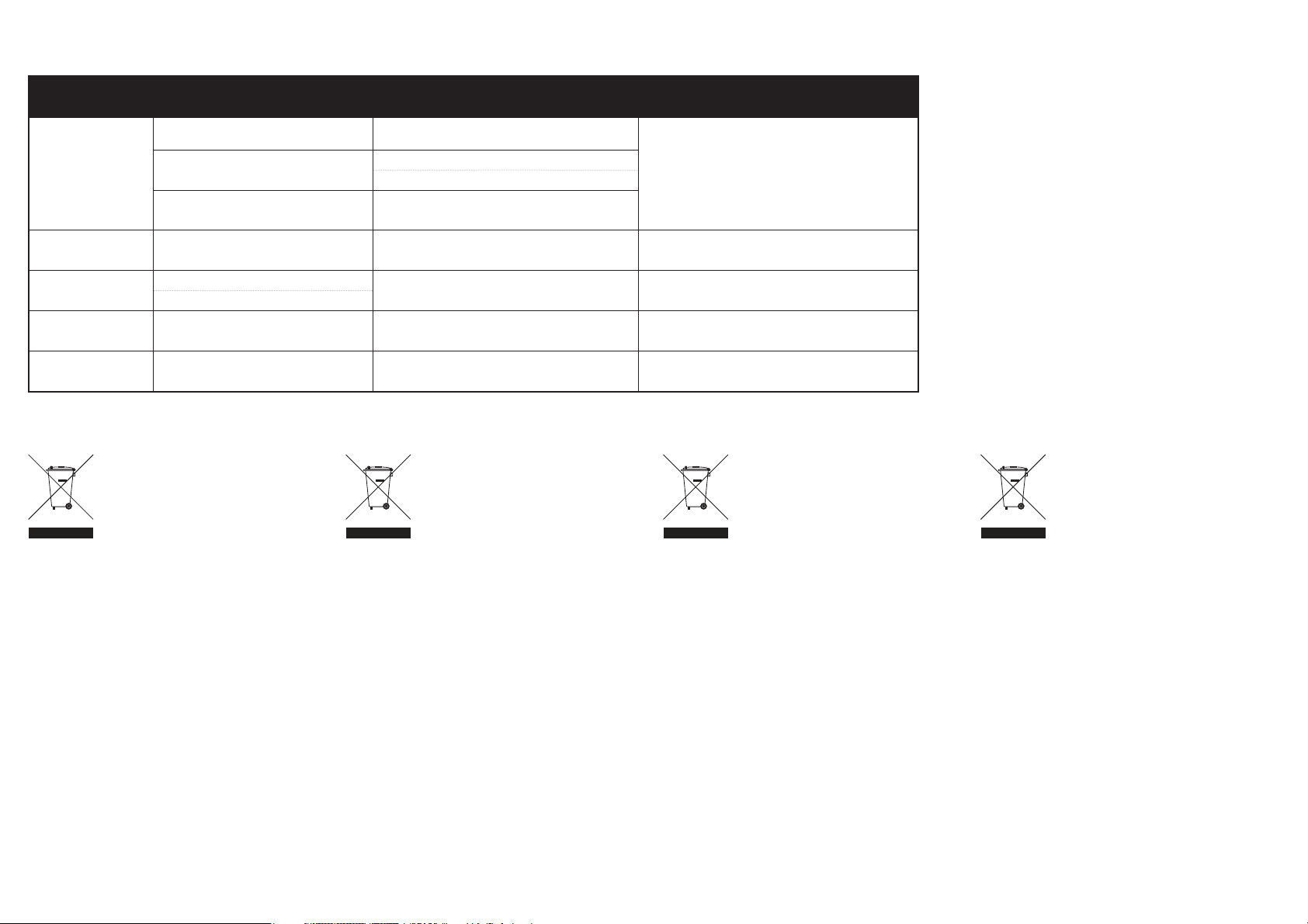
WARRANTY AND SERVICE CONTACT INFORMATION•GARANTIE UND SERVICE KONTAKTINFORMATIONEN•
COORDONNÉES DE GARANTIE ET RÉPARATIONS•GARANZIA E REVISIONA INFORMAZIONI PER I CONTATTI
Country of
Purchase
United States
of America
United Kingdom
Germany
France
China
Horizon Service Center
(Repairs and Repair Requests)
Horizon Product Support
(Product Technical Assistance)
Sales
Service/Parts/Sales:
Horizon Hobby Limited
Service/Parts/Sales:
Horizon Hobby SAS
Service/Parts/Sales:
Horizon Hobby – China
Horizon Hobby Contact Information Address
INSTRUCTIONS FOR DISPOSAL
OF WEEE BY USERS IN THE
EUROPEAN UNION
This product must not be disposed of
with other waste. Instead, it is the user’s
responsibility to dispose of their waste equipment by
handing it over to a designated collections point for the
recycling of waste electrical and electronic equipment. The
separate collection and recycling of your waste equipment at
the time of disposal will help to conserve natural resources
and ensure that it is recycled in a manner that protects
human health and the environment. For more information
about where you can drop off your waste equipment
for recycling, please contact your local city offi ce, your
household waste disposal service or where you purchased
the product.
servicecenter.horizonhobby.com/RequestForm/
www.quickbase.com/db/bghj7ey8c?a=GenNewRecord
888-959-2305
[email protected]
888-959-2305
[email protected]
+44 (0) 1279 641 097
[email protected]
+33 (0) 1 60 18 34 90
[email protected]
+86 (021) 5180 9868
ANWEISUNGEN ZUR
ENTSORGUNG VON ELEKTROUND ELEKTRONIK-ALTGERÄTEN
FÜR BENUTZER IN DER
EUROPÄISCHEN UNION
Dieses Produkt darf nicht zusammen mit anderem Abfall
entsorgt werden. Stattdessen ist der Benutzer dafür
verantwortlich, unbrauchbare Geräte durch Abgabe
bei einer speziellen Sammelstelle für das Recycling
von unbrauchbaren elektrischen und elektronischen
Geräten zu entsorgen. Die separate Sammlung und das
Recycling von unbrauchbaren Geräten zum Zeitpunkt der
Entsorgung hilft, natürliche Ressourcen zu bewahren und
sicherzustellen, dass Geräte auf eine Weise wiederverwertet
werden, bei der die menschliche Gesundheit und die
Umwelt geschützt werden. Weitere Informationen dazu, wo
Sie unbrauchbare Geräte zum Recycling abgeben können,
erhalten Sie bei lokalen Ämtern, bei der Müllabfuhr für
Haushaltsmüll sowie dort, wo Siedas Produkt gekauft
haben.
4105 Fieldstone Rd
Champaign, Illinois, 61822 USA
Units 1–4 , Ployters Rd, Staple Tye
Harlow, Essex, CM18 7NS, United Kingdom
Christian-Junge-Straße 1
25337 Elmshorn, Germany
11 Rue Georges Charpak
77127 Lieusaint, France
Room 506, No. 97 Changshou Rd.
Shanghai, China 200060
INSTRUCTIONS RELATIVES
ÀL’ÉLIMINATION DES D3E POUR
LES UTILISATEURS RÉSIDANT
DANS L’UNION EUROPÉENNE
Ce produit ne doit pas être éliminé avec
d’autres déchets. Il est de la responsabilité de l’utilisateur
d’éliminer les équipements rebutés en les remettant àun
point de collecte désigné en vue du recyclage des déchets
d’équipements électriques et électroniques. La collecte et le
recyclage séparés de vos équipements usagés au moment
de leur mise au rebut aideront àpréserver les ressources
naturelles et àassurer le recyclage des déchets de manière
àprotéger la santé humaine et l’environnement. Pour plus
d’informations sur les points de collecte de vos équipements
usagés en vue du recyclage, veuillez contacter votre mairie,
votre service de collecte des ordures ménagères ou le
magasin dans lequel vous avez acheté le produit.
ISTRUZIONI PER LO
SMALTIMENTO DI RAEE DA
PARTE DI UTENTI DELL’UNIONE
EUROPEA
Questo prodotto non deve essere smaltito
assieme ai rifi uti domestici. È responsabilità dell’utente
lo smaltimento di tali rifi uti, che devono essere portati
in un centro di raccolta predisposto per il riciclaggio di
rifi uti elettrici eapparecchiature elettroniche. La raccolta
differenziata eil riciclaggio di tali rifi uti provenienti da
apparecchiature nel momento dello smaltimento aiuteranno
apreservare le risorse naturali egarantiranno un riciclaggio
adatto aproteggere il benessere dell’uomo edell’ambiente.
Per maggiori informazioni sui punti di riciclaggio si
invita acontattare l’uffi cio locale competente, il servizio
di smaltimento rifi uti oil negozio presso il quale èstato
acquistato il prodotto.
46
Page 47

AMA NATIONAL MODEL AIRCRAFT SAFETY CODE
Effective January 1, 2013
A. GENERAL:
A model aircraft is a non-human-carrying aircraft capable
of sustained fl ight in the atmosphere. It may not exceed
limitations of this code and is intended exclusively for
sport, recreation and/or competition. All model fl ights must
be conducted in accordance with this safety code and any
additional rules specifi c to the fl ying site.
(h) Not operate model aircraft while under the infl uence of
alcohol or while using any drug which could adversely affect
the pilot’s ability to safely control the model.
(i) Not operate model aircraft carrying pyrotechnic devices
which explode or burn, or any device which propels a
projectile or drops any object that creates a hazard to
persons or property.
Exceptions:
B. RADIO CONTROL (RC)
1. All pilots shall avoid fl ying directly over unprotected
people, vessels, vehicles or structures and shall avoid
endangerment of life and property of others.
2. A successful radio equipment ground-range check in
accordance with manufacturer’s recommendations will be
completed before the fi rst fl ight of a new or repaired model
aircraft.
7. Under no circumstances may a pilot or other person touch
a model aircraft in fl ight while it is still under power, except
to divert it from striking an individual. This does not apply to
model aircraft fl own indoors.
8. RC night fl ying requires a lighting system providing the
pilot with a clear view of the model’s attitude and orientation
at all times.
9. The pilot of a RC model aircraft shall:
1. Model aircraft will not be fl own:
(a) In a careless or reckless manner.
(b) At a location where model aircraft activities are
prohibited.
2. Model aircraft pilots will:
(a) Yield the right of way to all man carrying aircraft.
(b) See and avoid all aircraft and a spotter must be used
when appropriate. (AMA Document #540-D-See and Avoid
Guidance.)
(c) Not fl y higher than approximately 400 feet above ground
level within three (3) miles of an airport, without notifying
the airport operator.
(d) Not interfere with operations and traffi c patterns at any
airport, heliport or seaplane base except where there is a
mixed use agreement.
(e) Not exceed a takeoff weight, including fuel, of 55 pounds
unless in compliance with the AMA Large Model Aircraft
program. (AMA Document 520-A)
(f) Ensure the aircraft is identifi ed with the name and
address or AMA number of the owner on the inside or affi xed
to the outside of the model aircraft. (This does not apply to
model aircraft fl own indoors).
(g) Not operate aircraft with metal-blade propellers or with
gaseous boosts except for helicopters operated under the
provisions of AMA Document #555.
• Free Flight fuses or devices that burn producing smoke
and are securely attached to the model aircraft during
fl ight.
• Rocket motors (using solid propellant) up to a G-series size
may be used provided they remain attached to the model
during fl ight. Model rockets may be fl own in accordance
with the National Model Rocketry Safety Code but may not
be launched from model aircraft.
• Offi cially designated AMA Air Show Teams (AST) are
authorized to use devices and practices as defi ned within
the Team AMA Program Document (AMA Document #718).
(j) Not operate a turbine-powered aircraft, unless in
compliance with the AMA turbine regulations. (AMA
Document #510-A).
3. Model aircraft will not be fl own in AMA sanctioned events,
air shows or model demonstrations unless:
(a) The aircraft, control system and pilot skills have
successfully demonstrated all maneuvers intended or
anticipated prior to the specifi c event.
(b) An inexperienced pilot is assisted by an experienced pilot.
4. When and where required by rule, helmets must be
properly worn and fastened. They must be OSHA, DOT, ANSI,
SNELL or NOCSAE approved or comply with comparable
standards.
3. At all fl ying sites a safety line(s) must be established
in front of which all fl ying takes place (AMA Document
#706-Recommended Field Layout):
(a) Only personnel associated with fl ying the model aircraft
are allowed at or in front of the safety line.
(b) At air shows or demonstrations, a straight safety line
must be established.
(c) An area away from the safety line must be maintained for
spectators.
(d) Intentional fl ying behind the safety line is prohibited.
4. RC model aircraft must use the radio-control frequencies
currently allowed by the Federal Communications
Commission (FCC). Only individuals properly licensed by the
FCC are authorized to operate equipment on Amateur Band
frequencies.
5. RC model aircraft will not operate within three (3)
miles of any pre-existing fl ying site without a frequencymanagement agreement (AMA Documents #922-Testing for
RF Interference; #923- Frequency Management Agreement)
6. With the exception of events fl own under offi cial AMA
Competition Regulations, excluding takeoff and landing, no
powered model may be fl own outdoors closer than 25 feet to
any individual, except for the pilot and the pilot’s helper(s)
located at the fl ight line.
(a) Maintain control during the entire fl ight, maintaining
visual contact without enhancement other than by corrective
lenses prescribed for the pilot.
(b) Fly using the assistance of a camera or First-Person View
(FPV) only in accordance with the procedures outlined in AMA
Document #550.
Please see your local or regional modeling association’s
guidelines for proper, safe operation of your model aircraft.
FAA INFORMATION
Prior to fl ying, contact your local or regional modeling
organizations for guidance and familiarize yourself with the
current local rules and FAA regulations governing model
aviation in your location.
More information about model aviation can be found at www.
modelaircraft.org.
The Federal Aviation Administration can be found online at
www.faa.gov.
47
Page 48

© 2013 Horizon Hobby, Inc.
Hangar 9, Evolution, Celectra, JR, DSMX, EC5, E-fl ite and the Horizon Hobby logo are trademarks or registered trademarks of Horizon Hobby, Inc.
The Spektrum trademark is used with permission of Bachmann Industries, Inc.
Sbach and its design are trademarks of STO Streicher GmbH & Co. KG registered in Germany and used with permission.
Sbach and its design are trademarks of XtremeAir GmbH registered in the U.S. and used with permission.
All other trademarks, service marks and logos are the property of their respective owners.
Job #31841 Created 01/2013
 Loading...