

Page 1
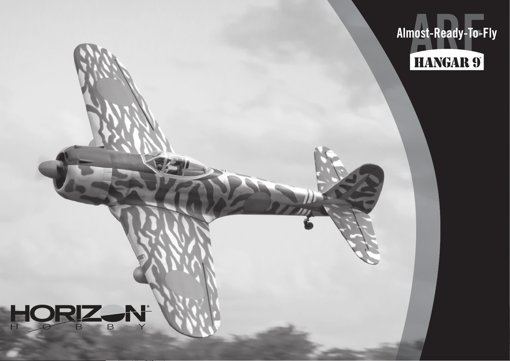
Ki-43 Oscar 60cc
Instruction Manual
Bedienungsanleitung
Manuel d’utilisation
Manuale di Istruzioni
Page 2
NOTICE
All instructions, warranties and other collateral documents are subject to change at the sole discretion of Horizon
Hobby, LLC. For up-to-date product literature, visit horizonhobby.com or www.towerhobbies.com and click on the
support or resources tab for this product.
MEANING OF SPECIAL LANGUAGE
The following terms are used throughout the product literature to indicate various levels of potential harm when
operating this product:
WARNING: Procedures, which if not properly followed, create the probability of property damage, collateral damage,
and serious injury OR create a high probability of superfi cial injury.
CAUTION: Procedures, which if not properly followed, create the probability of physical property damage AND a
possibility of serious injury.
NOTICE: Procedures, which if not properly followed, create a possibility of physical property damage AND a little or
no possibility of injury.
WARNING: Read the ENTIRE instruction manual to become familiar with the features of the product before
operating. Failure to operate the product correctly can result in damage to the product, personal property and
cause serious injury.
This is a sophisticated hobby product. It must be operated with caution and common sense and requires some basic
mechanical ability. Failure to operate this Product in a safe and responsible manner could result in injury or damage
to the product or other property. This product is not intended for use by children without direct adult supervision. Do
not attempt disassembly, use with incompatible components or augment product in any way without the approval
of Horizon Hobby, LLC. This manual contains instructions for safety, operation and maintenance. It is essential to
read and follow all the instructions and warnings in the manual, prior to assembly, setup or use, in order to operate
correctly and avoid damage or serious injury.
Age Recommendation: Not For Children Under 14 Years. This Is Not A Toy.
SAFETY WARNINGS AND PRECAUTIONS
Read and follow all instructions and safety precautions before use. Improper use can result in fi re, serious injury and
damage to property.
Components
Use only with compatible components. Should any compatibility questions exist, please refer to the product
instructions, component instructions or contact the appropriate Horizon Hobby offi ce.
Flight
Fly only in open areas to ensure safety. It is recommended fl ying be done at radio control fl ying fi elds. Consult local
ordinances before choosing a fl ying location.
Propeller
Always keep loose items that can become entangled in the propeller away from the prop. This includes loose clothing
or other objects such as pencils and screwdrivers. Keep your hands away from the propeller as injury can occur.
Batteries
Always follow the manufacturer’s instructions when using and disposing of any batteries. Mishandling of Li-Po
batteries can result in fi re causing serious injury and damage.
Small Parts
This kit includes small parts and should not be left unattended near children as choking and serious injury could result.
SAFE OPERATING RECOMMENDATIONS
• Inspect your model before every fl ight to ensure it is airworthy.
• Be aware of any other radio frequency user who may present an interference problem.
• Always be courteous and respectful of other users in your selected fl ight area.
• Choose an area clear of obstacles and large enough to safely accomodate your fl ying activity.
• Make sure this area is clear of friends and spectators prior to launching your aircraft.
• Be aware of other activities in the vicinity of your fl ight path that could cause potential confl ict.
• Carefully plan your fl ight path prior to launch.
• Abide by any and all established AMA National Model Aircraft Safety Code.
BEFORE STARTING ASSEMBLY
• Remove parts from bag.
• Inspect fuselage, wing panels, rudder and stabilizer for damage.
• If you fi nd damaged or missing parts, contact your place of purchase.
• Charge transmitter and receiver batteries.
• Center trims and sticks on your transmitter.
• For a computer radio, create a model memory for this particular model.
• Bind your transmitter and receiver, using your radio system’s instructions.
NOTICE: Rebind the radio system once all control throws are set. This will keep the servos from moving to their
endpoints until the transmitter and receiver connect. It will also guarantee the servo reversal settings are saved in the
radio system.
FAA INFORMATION
If you own this product, you may be required to register with the FAA.
For up-to-date information on how to register with the FAA, please visit https://registermyuas.faa.gov/.
For additional assistance on regulations and guidance on UAS usage, visit knowbeforeyoufl y.org/.
2EN
Page 3
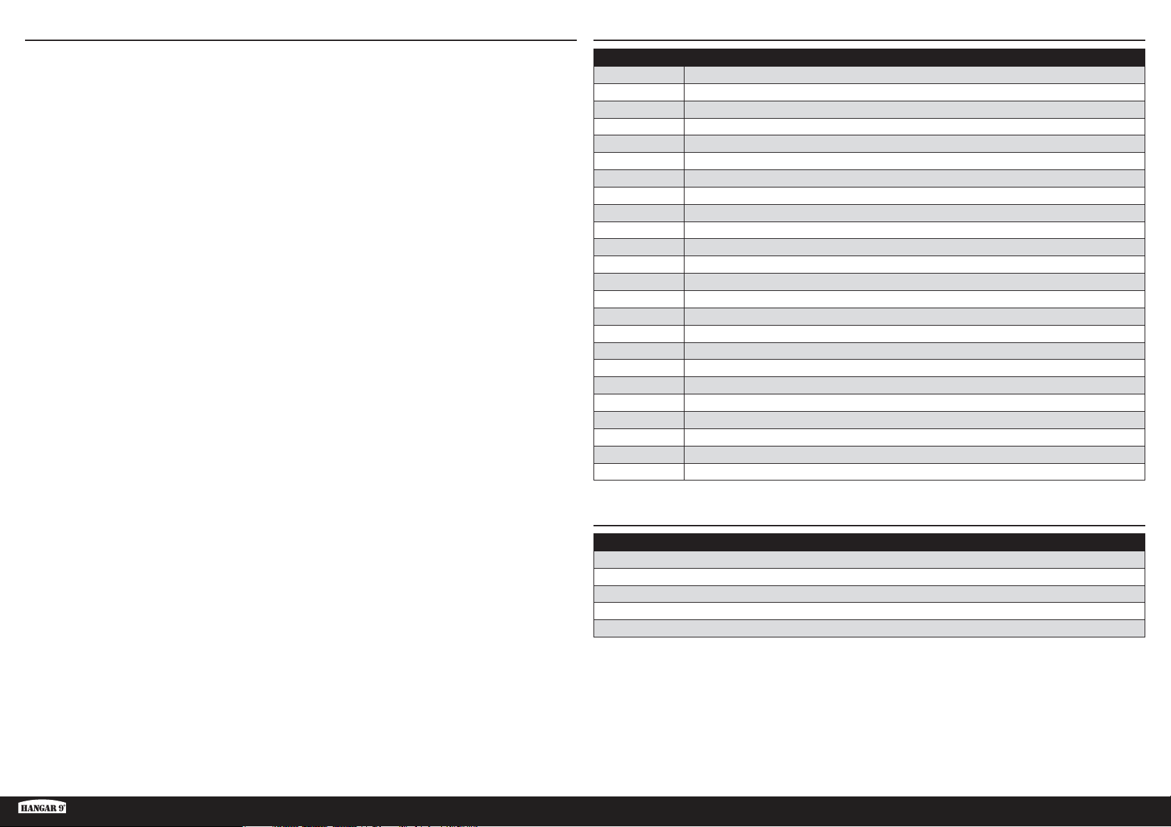
Notice ......................................................................................................................................................................2
Meaning of Special Language ..................................................................................................................................2
Safety Warnings and Precautions .............................................................................................................................2
Safe Operating Recommendations ...........................................................................................................................2
Before Starting Assembly .........................................................................................................................................2
FAA Information .......................................................................................................................................................2
Replacement Parts ...................................................................................................................................................3
Required Adhesives .................................................................................................................................................3
Required for Completion, All Power Options ..............................................................................................................4
Required for Completion, Gas Engine Installation......................................................................................................4
Required for Completion, Electric Motor Installation .................................................................................................4
Optional Parts ..........................................................................................................................................................4
Tools Required .........................................................................................................................................................4
Printed Covering Notes ............................................................................................................................................5
Building Precautions ................................................................................................................................................5
Transportation and Storage ......................................................................................................................................5
Checking Blind Nuts.................................................................................................................................................5
Nose Weight ............................................................................................................................................................5
For the Visually Challenged ......................................................................................................................................5
Retract Installation ...................................................................................................................................................5
Aileron Installation ...................................................................................................................................................9
Hinging the Ailerons ...............................................................................................................................................11
Aileron Servo Installation .......................................................................................................................................12
Hinging the Flaps ...................................................................................................................................................14
Flap Servo Installation............................................................................................................................................15
Drop Tank Installation ............................................................................................................................................17
Stabilizer Installation ..............................................................................................................................................18
Elevator Installation ...............................................................................................................................................20
Rudder Installation .................................................................................................................................................21
Rudder Linkage Installation ....................................................................................................................................21
Tail Wheel Installation ............................................................................................................................................22
Pilot and Canopy Installation ..................................................................................................................................24
Electric Motor Installation .......................................................................................................................................25
Gas Engine Installation ...........................................................................................................................................27
Fuel Tank Installation .............................................................................................................................................29
Retract Air System Installation ...............................................................................................................................30
Receiver Installation ...............................................................................................................................................32
Cowling and Spinner Installation ............................................................................................................................32
Center of Gravity ....................................................................................................................................................34
Control Throws ......................................................................................................................................................35
Prefl ight Checklist ..................................................................................................................................................35
Daily Flight Checks ................................................................................................................................................35
Limited Warranty ...................................................................................................................................................35
Warranty and Service Contact Information .............................................................................................................36
Instructions for Disposal of WEEE by Users in the European Union ..........................................................................36
Academy of Model Aeronautics National Model Aircraft Safety Code .......................................................................37
REPLACEMENT PARTSTABLE OF CONTENTS
Part # Description
HAN472001 KI-43 Oscar 60cc Airframe Only
HAN472002 Fuselage with Hatch: Ki-43 60cc
HAN472003 LH Wing with Aileron & Flap: Ki-43 60cc
HAN472004 RH Wing with Aileron & Flap: Ki-43 60cc
HAN472005 Stabilizer with Elevator: KI-43 60cc
HAN472006 Rudder: Ki-43 60cc
HAN472007 Cowling & Dummy Engine:Ki-43 60cc
HAN472008 Top Hatch: Ki-43 60cc
HAN472009 Canopy: Ki-43 60cc
HAN472010 Painted Pilot: Ki-43 60cc
HAN472011 Hardware Set: Ki-43 60cc
HAN472012 Mainwheels 5-inch: Ki-43 60cc
HAN472013 Tail Wheel Assembly: Ki-43 60cc
HAN472014 Pushrod Set: Ki-43 60cc
HAN472015 Spinner 3
HAN472016 Wing Tube: Ki-43 60cc
HAN472017 Fuel Tank: Ki-43 60cc
HAN472018 EP Motor Mount: Ki-43 60cc
HAN472019 Gear Door Set: Ki-43 60cc
HAN472020 Scale Details: Ki-43 60cc
HAN472025 Retract Set: Ki-43 60cc
HAN472026 Retracts and Struts: Ki-43 60cc
HAN472027 Air System Hardware: Ki-43 60 cc
HAN472028 Retract Struts: Ki-43 60cc
3
/4-inch: Ki-43 60cc
REQUIRED ADHESIVES
Description
15-minute epoxy
30-minute epoxy
Thin CA
Medium CA
Threadlock, low and high strength
Ki-43 Oscar 60cc ARF
3 EN
Page 4
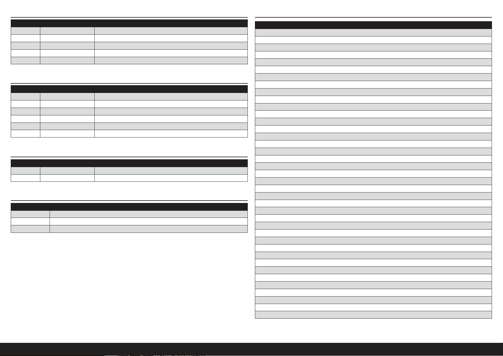
REQUIRED FOR COMPLETION, ALL POWER OPTIONS
# Required Part # Description
1 SPMAR12310T AR12310T 12CH PowerSafe Tele RX
7 SPMSA6320 A6320 H-T/H-S Brushless HV Servo
1 SPMSA6110 A6110 M-T / M-S Standard HV Servo (retract air valve)
2 SPMA3000 Heavy-Duty Servo Extension 3-inch
4 SPMA3002 Heavy-Duty Servo Extension 9-inch
REQUIRED FOR COMPLETION, GAS ENGINE INSTALLATION
# Required Part # Description
2 SPMSA6110 A6110 M-T / M-S Standard HV Servo (throttle and choke)
1 DLEG0061 DLE-61cc Gas Engine w/Elec Ignition
1 DUB800 Tygon Gas Tubing, 3' Large
1 HAN116 Fuel Filler with “T" and Overfl ow Fittings
1 SPM9530 Spektrum 3-Wire Switch Harness
3 SPMB4000LPRX 4000mAh 2S 7.4V LiPo Rx Battery
REQUIRED FOR COMPLETION, ELECTRIC MOTOR INSTALLATION
# Required Part # Description
1 GPMG4805 Rimfi re 65cc Electric Motor
1 CSE010013100 Talon HV120 ESC 010-0131-00
OPTIONAL PARTS
Part # Description
EVOA100 Optical Ignition Kill Switch
SAIEG90R3 FG-90R3 90cc 3-Cyl Radial Engine
SPMAS3000 AS3000 AS3X Stabilization Module
TOOLS REQUIRED
Description
Adjustable wrench
Balancing stand
Box wrench: 14mm and 17mm
Crimping tool
Drill and tap set, metric
Drill bit set, Imperial or Metric
Epoxy brushes
Felt-tipped pen
Hemostats
Hex wrench set, Imperial and Metric
Hobby knife with #11 blade
Hobby scissors
Hook and loop straps
Hook and loop tape
Isopropyl alcohol
Light machine oil
Low-tack tape
Mixing sticks
Needle nose pliers
Nut driver set, Imperial and Metric
Paper towels
Pencil
Petroleum jelly
Phillips screwdriver: #1, #2
Pin vise
Razor saw
Rotary tool
Ruler
Sanding bar
Sanding drum for rotary tool
Sandpaper
Scissors
Side cutters
Square
Tap handle
Tapered reamer
Tie wraps
Toothpicks
Wire stripper
4EN
Page 5
PRINTED COVERING NOTES
• The covering used on your model has the coloring and markings printed directly on the covering.
• The covering has a self-adhesive backing, and it is not recommended to use heat as it may damage the covering.
• Use only mild cleaning agents on the printed fi nish. Denatured alcohol is the most aggressive agent we recommend,
but test on an inconspicuous area fi rst. Prolonged use will remove the paint.
• Use tape with care. Anything other than low-tack tape can remove the fi nish, particularly on edges.
• Avoid contact with raw fuel, especially alcohol-based fuels containing nitro methane.
• Remove exhaust residue as soon as practical to avoid staining or damaging of the fi nish.
There are two areas on your aircraft that will receive wear under normal use. The fi rst area is where the cowling fi ts
over the fuselage hatch, and where the wing fi ts into the fuselage. Placing a piece of clear tape on the wing where it
fi ts into the fuselage, and on the hatch underneath the cowling, will reduce the wear on the covering in these areas.
Sanding the inside of the cowling smooth will also help prevent wear of the covering under the cowling.
BUILDING PRECAUTIONS
Prepare the work surface prior to beginning the build. The surface should be soft and free of any sharp objects. We
recommend resting the airframe parts on a soft towel or pit mat to prevent scratching or denting the surface of the
aircraft.
TRANSPORTATION AND STORAGE
When transporting and storing your model, you will need a minimum of 70 inches (1.8m) in length, and 28 inches
(54cm) in height to accommodate the size of the fuselage. We also recommend the use of wing and stabilizer bags to
help protect these surfaces during transport and storage. The control horns and linkages can cause damage to other
surfaces even when placed in storage bags. Always transport and store the wings and stabilizer so the linkages do not
contact other panels to prevent damage.
CHECKING BLIND NUTS
When building the aircraft, you will be required to thread machine screws into blind nuts. We recommend pre-threading
the screws to make sure the blind nuts are clear of any debris. If the screws do not thread in easily, clear the threads
using the appropriate tap and tap handle.
NOSE WEIGHT
This model will likely require the addition of nose weight to properly balance. Testing has been performed on all power
options. Using a heavier engine or motor will help in reducing the amount of weight required. Make sure to use proper
throttle management when fl ying with these larger and more powerful options. Our test aircraft with the recommended
Evolution® 62cc engine and muffl er, and receiver and ignition batteries under the fuel tank. Using engines other than
those recommended may require the additional weight to properly balance. This may vary from plane to plane. Add this
weight as far forward in the fuselage as possible to reduce the amount required to balance. This weight must be secure
so it does not come loose in fl ight, causing an unsafe model which could result in the loss of the aircraft.
RETRACT INSTALLATION
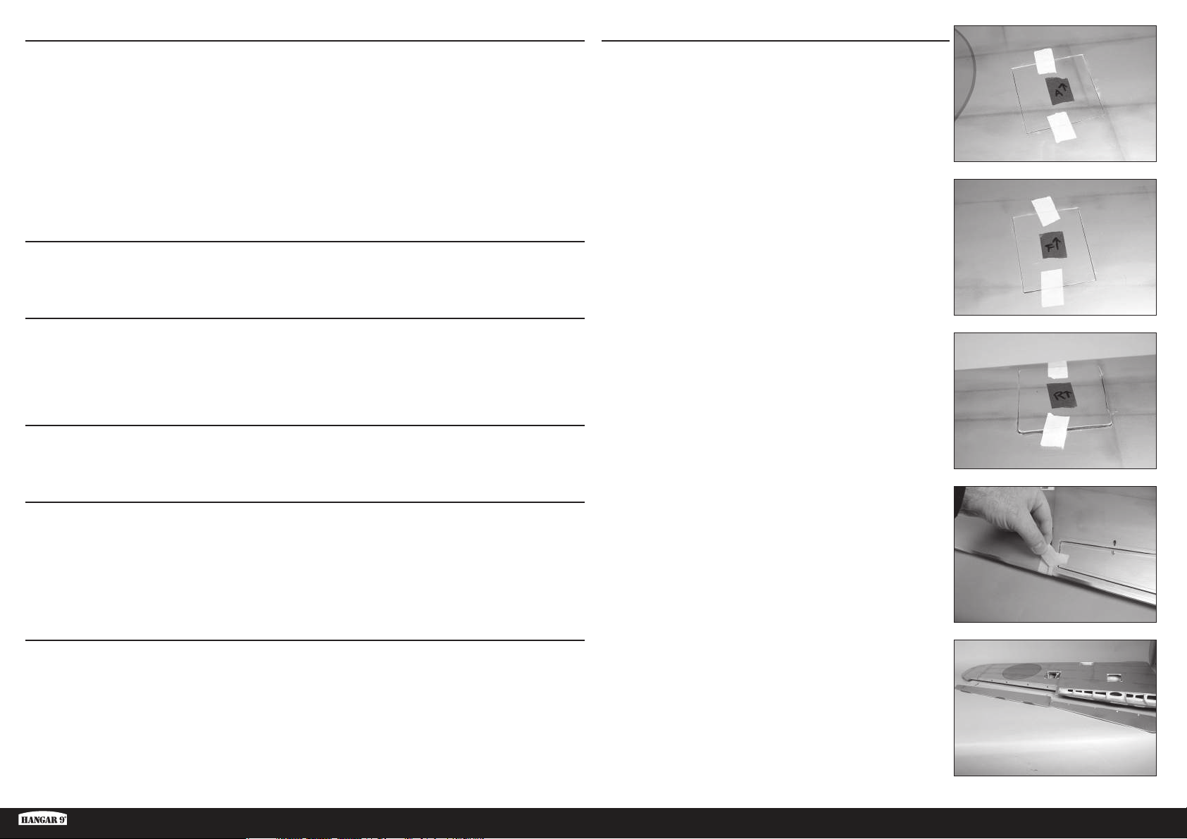
1. Use low-tack tape to mark the aileron, fl ap and retract covers so
they can be returned to the wing in the correct orientation. Use an
arrow pointing toward the leading edge as reference.
2. Remove the tape from the wing that secure the aileron and fl ap to
the wing.
FOR THE VISUALLY CHALLENGED
A copy of this manual can be found at www.horizonhobby.com under the tab for this particular model. Feel free to
download this manual and use a PDF viewer to zoom in on any text or images that may be in question when building
from the printed manual.
Ki-43 Oscar 60cc ARF
3. Separate the aileron and fl ap from the wing. Set them aside in a safe
location.
5 EN
Page 6
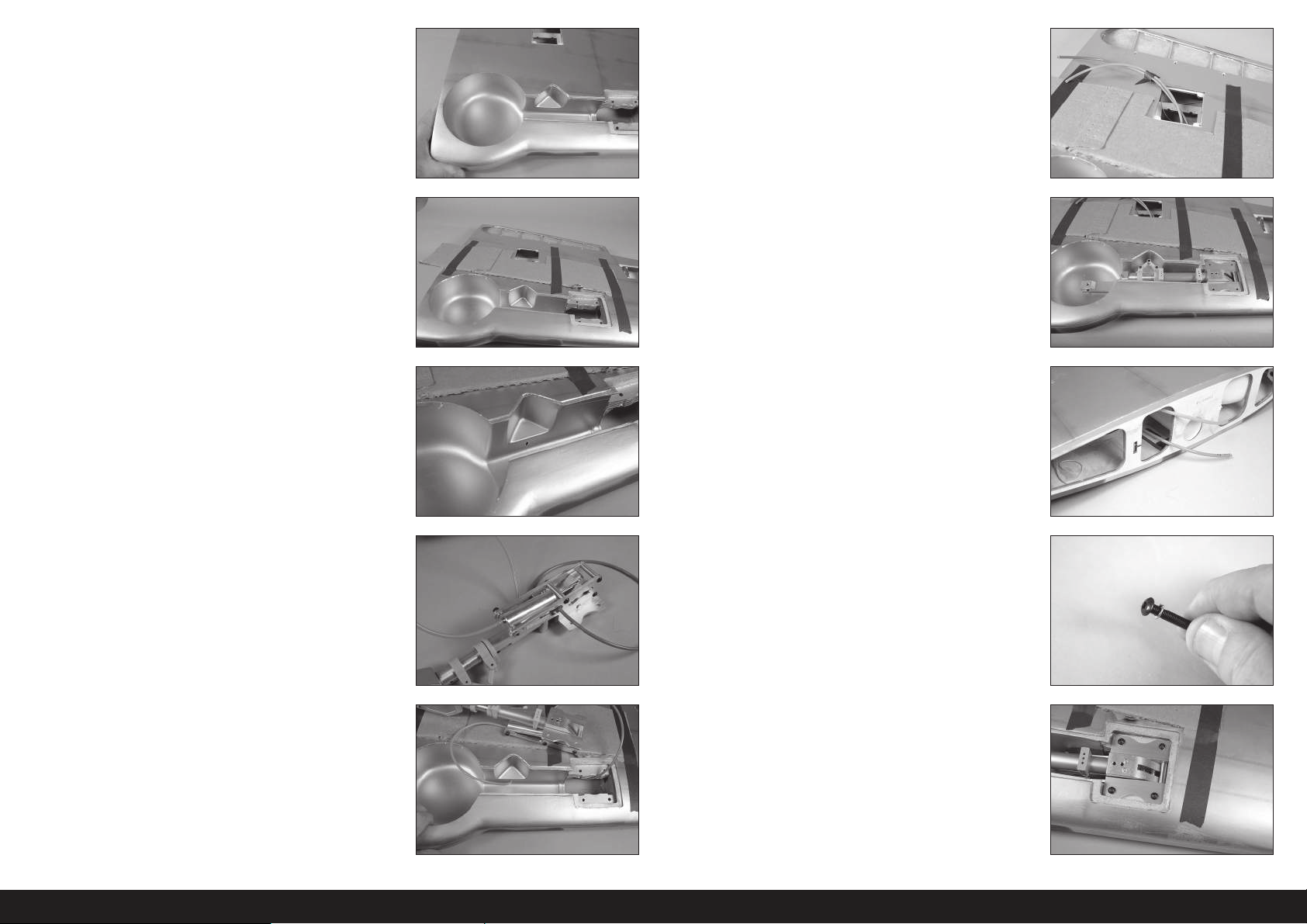
4. Use a hobby knife and #11 blade to remove the covering from the
retract openings in the wing. Trim the covering inside the opening.
9. Both air lines can be retrieved at the fl ap servo opening. Use a piece
of low-tack tape to secure the lines together so they don’t fall back
into the wing.
5. Use low-tack tape to secure a piece of cardboard over the wing. This
will provide a place to rest the retract when routing the air lines and
prevent damage to the underside of the wing.
6. Use a pin vise and 1/8-inch (3mm) drill bit to make a hole in the
retract well for the air line.
7. Cut a 19-inch (482mm) piece of the orange and blue air line. Attach
each air line to the retract. Using different colors makes connecting
the retracts correctly much easier when assembling the model.
Use a heat gun on low to soften the air lines
slightly so they will slide on the fittings.
Make sure to orient the air line colors the same on both the
left and right retracts so they operate in the same manner.
10. Fit the retract in the wing. Trim as necessary to provide clearance.
11. The air lines can now be retrieved at the wing root.
12. Place a lock washer on the M4 x 25 button head cap screw. Prepare
four screws at this time.
8. Route the air lines into the wing.
13. Use the M4 x 25 button head cap screws to secure the retract in the
wing. Place a drop of threadlock on each of the screws before their
installation. Tighten the screws using a 2.5mm hex wrench.
The cardboard can be removed from the wing
after the retract has been secured.
It may be necessary to use spacers under the retract frame to
make sure there is no torsional stress when tightened into position.
Torsional stress can cause intermittent operation of the retract unit.
6EN
Page 7
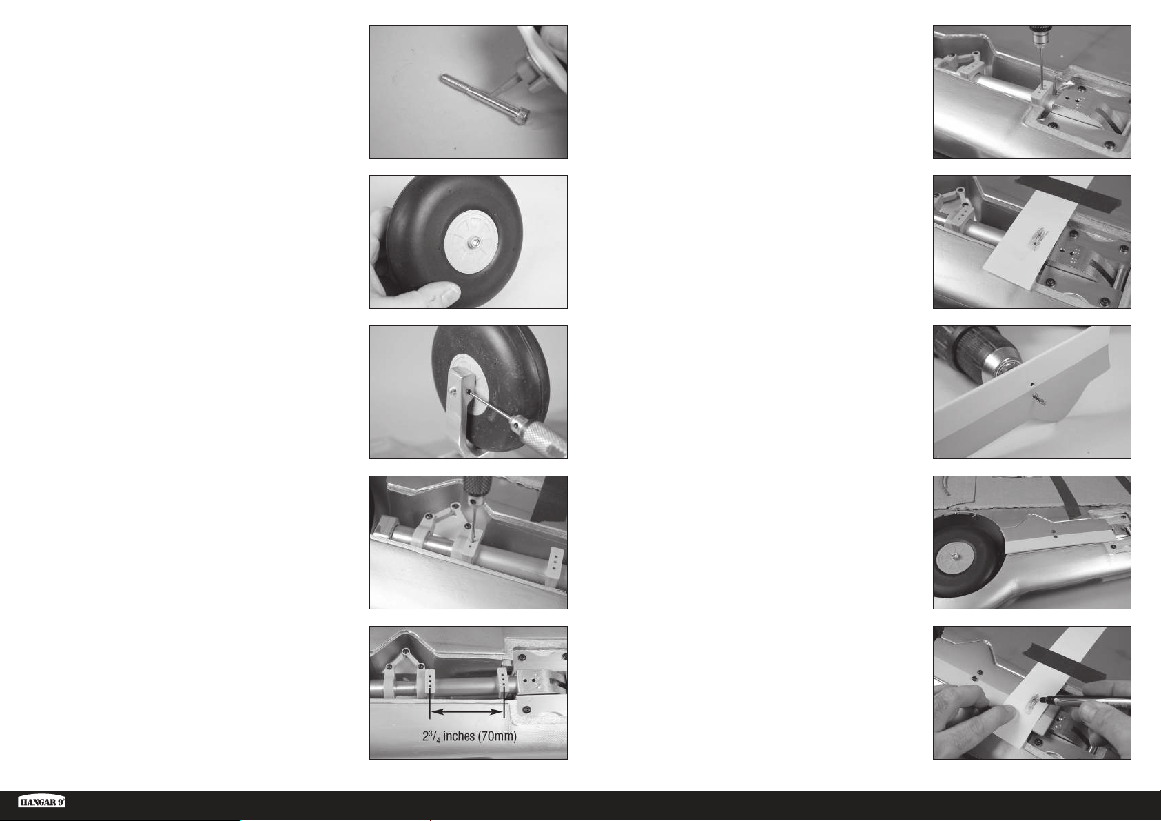
14. Place a drop of light machine oil on the M6 x 55 socket head cap
screw that will function as the wheel axle.
19. Use an M3 x 5 setscrew and 1.5mm hex wrench to secure the
position of the gear door mount.
Do not over tighten the screws or use threadlock as it
will damage the composite material of the mounts.
15. Slide the M6 x 55 socket head cap screw through the wheel. Make
sure the wheel spins freely on the screw.
16. Thread the screw into the retract. Tighten the screw enough that the
wheel can spin freely, yet there isn’t any excess movement of the
wheel on the screw. Once set, use an M3 x 5 setscrew and 2mm hex
wrench to tighten the setscrew. Use a drop of threadlock on both
the M6 x 55 socket head cap screw and M3 x 5 setscrew to prevent
them from vibrating loose.
17. Position the gear door mount near the wheel as close to the wheel
as possible. The fl at area will align with the bottom of the wing. Use
an M3 x 5 setscrew and 1.5mm hex wrench to secure the position of
the gear door mount.
Do not over tighten the screws or use threadlock as it
will damage the composite material of the mounts.
20. Tape a piece of paper to the wing that will go over the upper mount.
Rub a pencil on the paper to reveal the locations for the mounting
holes.
21. Use a drill and 1/8-inch (3mm) drill bit to drill the holes for the lower
gear mounting holes in the gear door.
22. Attach the gear door to the mount using two M3 x 12 button head
screws and a 2mm hex wrench.
Check the positioning of the door to make sure it is centered
in the opening and aligns with the opening near the wheel.
Do not over tighten the screws or use threadlock as it
will damage the composite material of the mounts.
18. Position the upper mount 23/4 inches (70mm) from the lower mount.
Ki-43 Oscar 60cc ARF
23. Use a felt-tipped pen to mark the location for the upper gear door
mounting screws on the gear door.
7 EN
Page 8
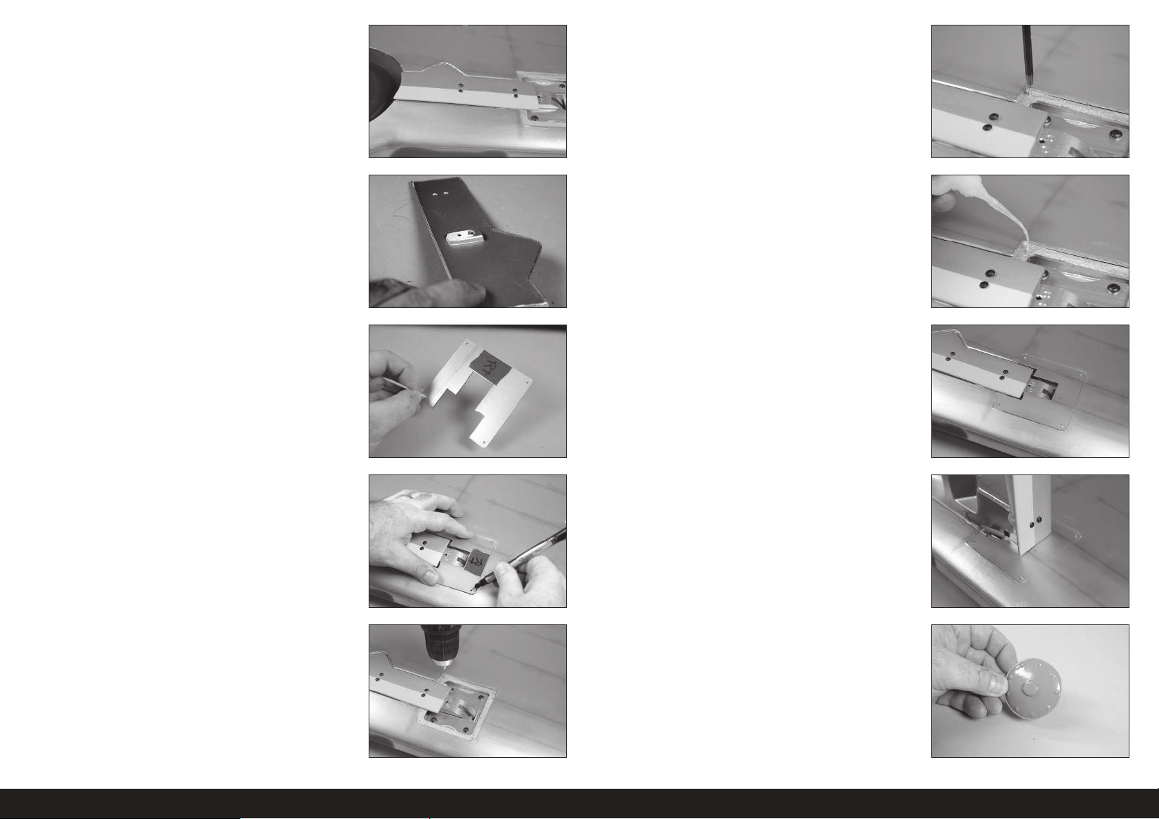
24. Remove the cover and use a drill and 1/8-inch (3mm) drill bit to drill
the two holes for the upper gear door mounting screws. The door
can now be attached to the mounts using the four M3 x 12 button
head screws and 2mm hex wrench.
29. Thread an M2 x 10 sheet metal screw into each hole using a #1
Phillips screwdriver. Remove the screws before proceeding.
25. If the gear door is not fl ush with the bottom of the wing, the mounts
may need to be adjusted. The mounting area for the lower mount
can also be sanded using medium grit sandpaper to make any
adjustments to the gear door alignment.
26. Use a hobby knife or other sharp tool to puncture the covering at the
screw holes that will secure the cover to the wing. Also remove the
covering to clear the retract mechanism.
27. Place the cover into position. Use a felt-tipped pen to mark the
locations for the mounting screws
30. Apply a small amount of thin CA to harden the threads made in the
previous step. Allow the CA to fully cure before installing the retract
cover.
31. Secure the retract cover to the wing using four M2 x 10 sheet metal
screws. Use a #1 Phillips screwdriver to tighten the screws.
32. Check that the retract can be fully extended without the gear door
hitting the cover. Trim the gear door as necessary if it hits the cover.
There will be movement in the gear during their operation so
make sure there is a gap between the gear door and wing so
they do not contact each other during the operation of the gear.
28. Use a pin vise and 1/16-inch (1.5mm) drill bit to drill the mounts for
the retract covers.
33. Use hobby scissors and medium grit sandpaper to prepare the hub
caps for installation.
The hub caps can be painted if desired. Be sure to fully scuff and
prepare the surface. Applying paint directly to the hub cap with
no preparation will result in flaking paint. Always test paint on a
piece of scrap material to check its compatibility to the plastic.
8EN
Page 9
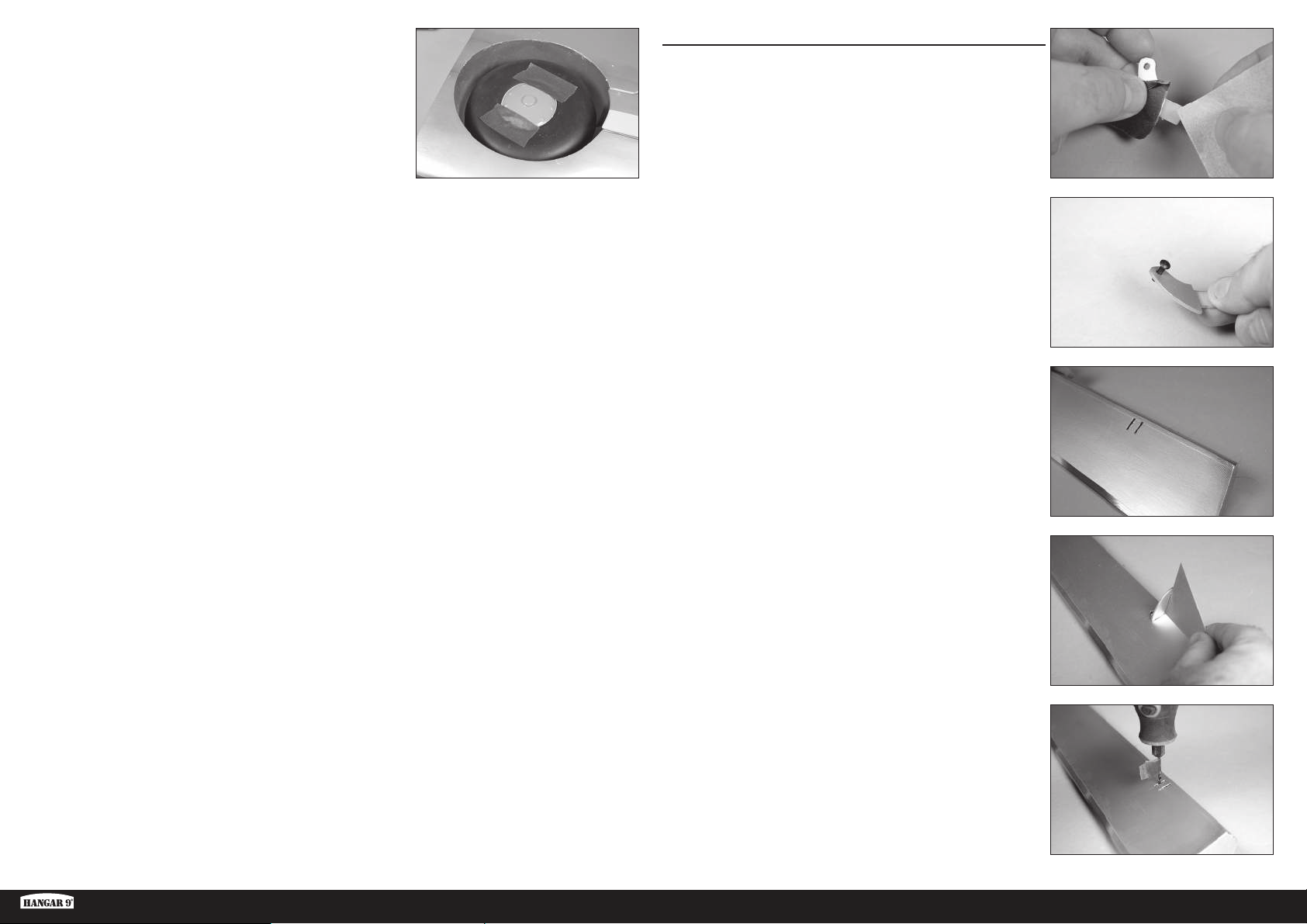
34. Use contact adhesive to glue the hub cap to the wheel. Use low-tack
tape to hold the hub cap in position until the adhesive fully cures.
Repeat this section to install the remaining retract assembly.
AILERON INSTALLATION
1. Use medium-grit sandpaper to lightly sand the control horn where
it fi ts into the control surface. Clean the sanded area using a paper
towel and isopropyl alcohol to remove any debris or oils. This
provides the surface texture necessary for the epoxy to bond to.
Use tape on the painted area to help prevent removing
the exposed portion of the control horn. Remove the
tape once the control horn has been sanded.
2. Insert the M3 x 10 button head screw into the hole in the control
horn. Remove any paint using a hobby knife and #11 blade so the
screw fi ts into the hole easily. Check all the control horns.
The hole should be just large enough for the screw to slide
through, yet still fit snugly in the hole and not move excessively.
3. Run your fi nger along the bottom of the aileron to locate the area
for the control horn. Use a hobby knife and #11 blade to remove the
covering, exposing the slots for the control horn.
Ki-43 Oscar 60cc ARF
4. Test fi t the control horn in the slot. Do not force the control horn into
the slot. Use a square to make sure the control horn is square to the
control surface. Do not force the control horn in the slot.
If the control horn fits tight, or is not square, use a rotary tool
3/32-inch (2.5mm) drill bit to carefully enlarge and reshape
the hole. Wrap a piece of low-tack tape around the drill
bit to set the depth of the drill bit so it won’t accidentally
pass through the opposite side of the control surface.
9 EN
Page 10
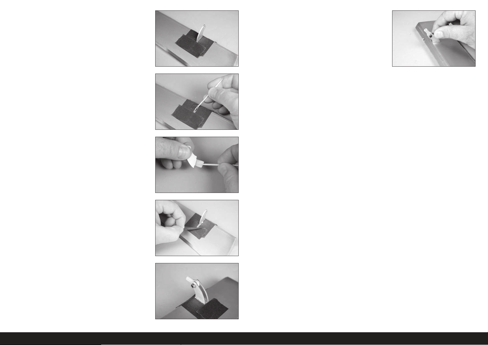
5. Place tape around the slot in the aileron for the aileron control horn.
6. Remove the control horns from the control surfaces. Apply epoxy to
the slot in the aileron. Make sure the epoxy gets into the slot for a
good bond between the surfaces and control horn.
7. Apply epoxy to the area of the control horn that fi ts into the slot. Use
enough epoxy so the control horn will be fully bonded to the control
surfaces.
10. Once the epoxy has fully cured, pull on the control horn to make
sure it is glued securely in the aileron. If not, remove the control horn
and sand off any adhesives. Repeat this section to glue the control
horn in the aileron.
8. Before the epoxy fully cures, remove the tape from around the
control horn. This will allow the epoxy to fl ow around the control
horn, creating a small fi llet between the control horn and surface for
a fi nished look and secure bond. Allow the epoxy to fully cure before
proceeding.
9. Test fi t the remaining control horn. When gluing the control horn,
place the ball end between the horns and insert the M3 x 10 button
head screw through the control horns and rod ends. This will align
the horns correctly, making the linkage installation easier later.
10EN
Page 11
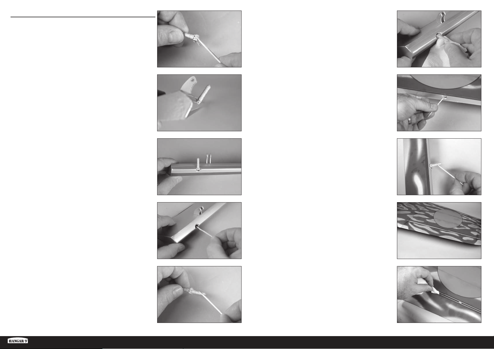
HINGING THE AILERONS
Do not mix any epoxy until instructed to do so.
Use the short hinges for the ailerons. The longer hinges are
used for the flaps due to the hinging technique used.
1. Apply a small amount of oil to the fl ex point of the hinge to prevent
epoxy from entering the hinge.
6. Insert the hinges into the control surface. Verify the hinge position
is correct. Use a paper towel and isopropyl alcohol to remove any
excess epoxy. Allow the epoxy to fully cure before proceeding.
2. Insert the hinge so the center of the hinge point aligns with the front
edge of the bevel on the control surface. Check that the hinge can
move freely.
3. Position the hinge so it is perpendicular to the hinge line when fully
defl ected.
4. Mix 1/2 ounces (15mL) of 30-minute epoxy. Remove the hinges,
then use a toothpick to apply epoxy inside each of the holes for the
hinges.
7. Mix 1/2 ounces (15mL) of 30-minute epoxy. Use a toothpick to apply
epoxy inside each of the holes for the hinges.
8. Apply epoxy to the outside of the hinge using a toothpick
9. Fit the aileron to the wing. Check that the aileron can move freely,
and the hinges are all aligned properly.
5. Apply epoxy to the outside of the hinge using a toothpick
Ki-43 Oscar 60cc ARF
10. Use a paper towel and isopropyl alcohol to remove any excess
epoxy. Use low-tack tape to hold the aileron in position until the
epoxy fully cures.
11 EN
Page 12
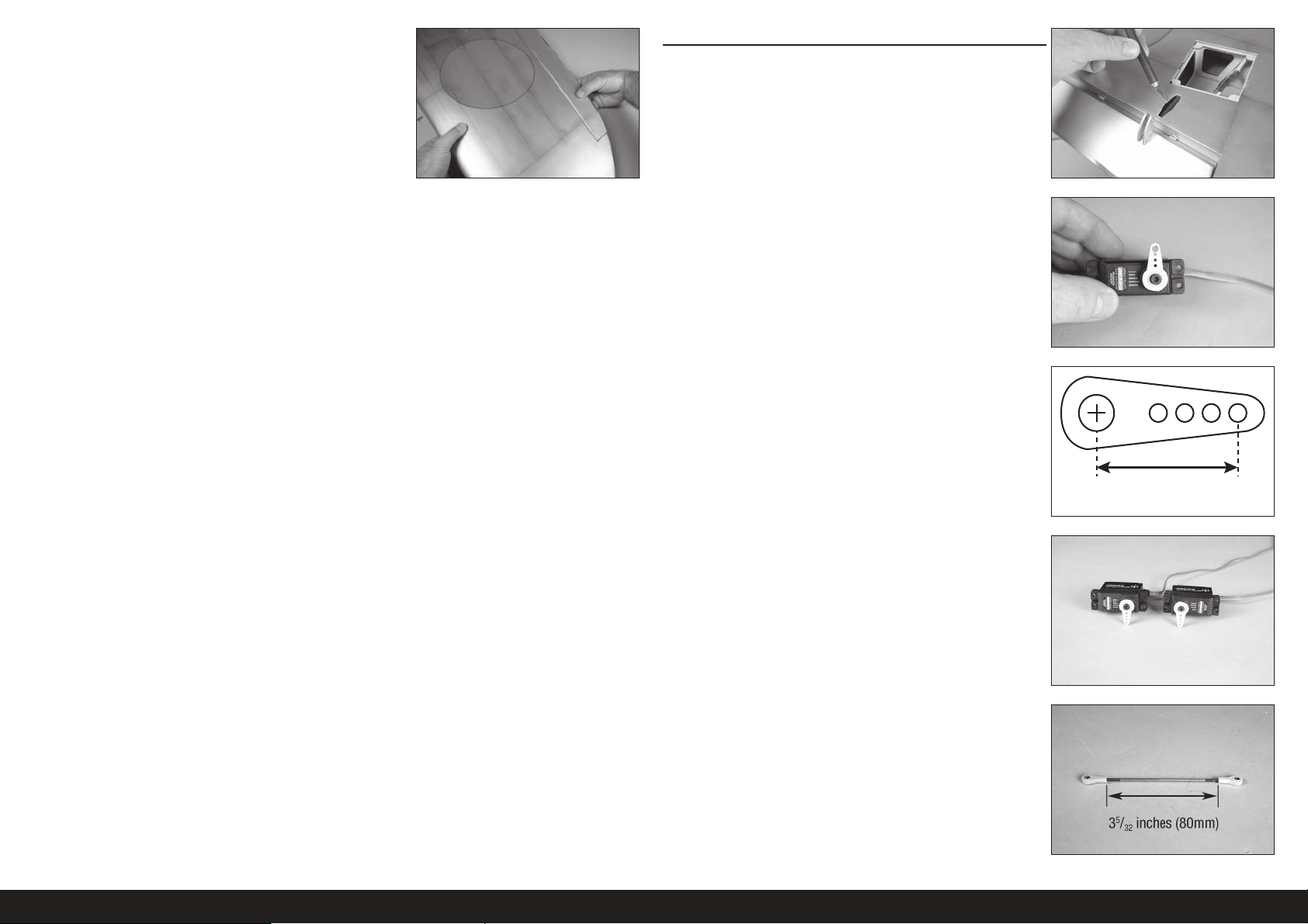
11. Once the epoxy has fully cured, pull on the wing and aileron to make
sure the hinges are glued securely. If not, remove the aileron and
sand off any adhesives. Repeat this section to glue the hinges.
AILERON SERVO INSTALLATION
1. Use a hobby knife and #11 blade to remove the covering for the
aileron pushrod exit.
2. Center the aileron servo. Attach the servo horn on the servo
perpendicular to the servo centerline.
3. When attaching the linkage to the aileron servo arm, use the hole in
the arm that is 5/8-inch (16mm) from the center of the arm.
5/8 inch
(16mm)
4. Prepare both the left and right aileron servos at this time.
5. Assemble the linkage for the aileron using two ball ends and the
15
/16 inch (100mm) threaded rod. Thread each ball end 12 turns
3
on the link. Adjust the length so the distance between the ball ends
measures 3
12EN
5
/32 inches (80mm).
Page 13
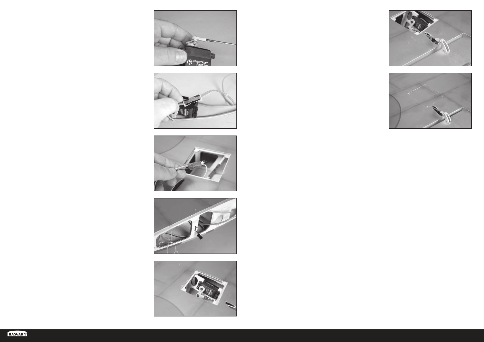
6. Secure the servo ball link to the servo arm using an M3 x 10 button
head screw, M3 washer and M3 lock nut. Use a 2.5mm hex wrench
and 5.5mm nut driver to tighten the hardware.
11. Secure the servo ball link to the control horn using an M3 x 10
button head screw, M3 washer and M3 lock nut. Use a 2.5mm hex
wrench and 5.5mm nut driver to tighten the hardware.
Connect the servo to the radio system to hold the aileron servo in
the centered position. Disconnect the ball from the control horn
and adjust the linkage so the aileron is in the neutral position.
Reinstall the hardware once the linkage has been adjusted.
7. Secure a 6-inch (150mm) servo extension to the servo using a
commercially available retainer (SPMA3054).
The length of the extension may vary depending on servo selection.
The extension listed works with the recommended servos.
8. Tie or tape the string located inside the wing to the end of the servo
lead.
9. Use the string to pull the servo lead through the wing and out at the
root.
We left a small amount of the string on the aileron
servo lead so it can be quickly differentiated between
the flap servo lead that will be installed later.
12. Use the steps outlined for the retract cover to install the aileron
cover.
10. Install the aileron servo in the wing with the output facing the
leading edge. Make sure to prepare the servo mounting holes by
threading a servo mounting screw into each hole and removing
them. Harden the mounting screw locations with thin CA before
installing the servo.
Ki-43 Oscar 60cc ARF
13 EN
Page 14
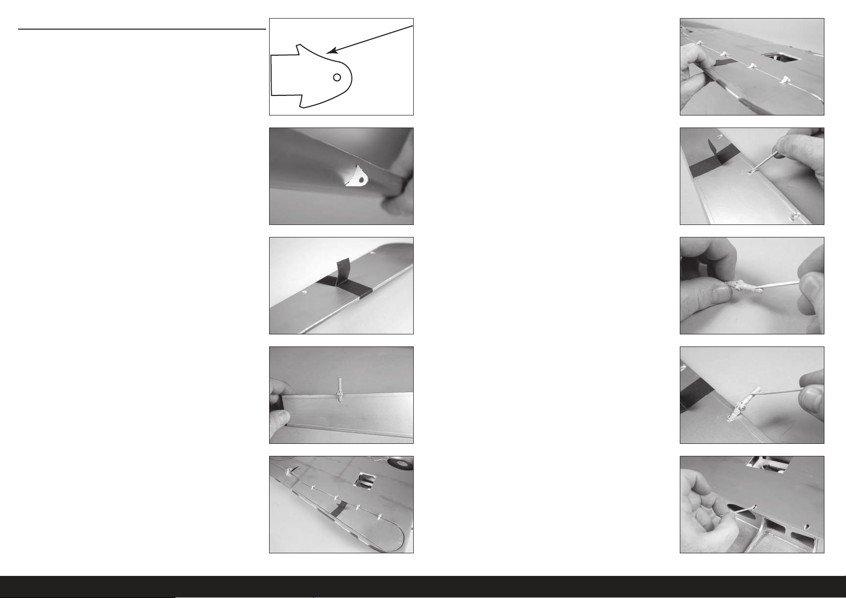
HINGING THE FLAPS
The flaps must be positioned to the wing before the epoxy
begins to cure. Make sure to read through all the steps
before mixing any epoxy. Glue only one flap at a time to
allow enough working time to properly install the hinges.
1. Locate the fl ap control horns. When installed, the concave portion of
the horn (as indicated in the drawing) will face toward the top of the
fl aps.
6. The fl ap will also align to the bottom of the wing when the hinges
are positioned correctly.
2. Run your fi nger down the leading edge of the fl ap to locate the
area for the fl ap control horns. Use a hobby knife and #11 blade to
remove the covering, exposing the slots for the control horn. Use
15-minute epoxy to glue the fl ap control horns in position. Remove
any excess epoxy using a paper towel and isopropyl alcohol.
Use the steps outlined for the aileron control horns to install the
flap control horns. Make sure to check that the flap control horns
are glued securely in the flaps once the adhesive fully cures.
3. Wrap a piece of low-tack tape around the fl ap to create a tab so the
fl ap can be lifted and lowered into position when fi tting the hinges.
Use the long hinges when installing the flaps to the wing.
4. Test fi t the hinges to the fl ap. Do not use any adhesives now. Slide
the hinge into position. Position as shown, checking to make sure it
can move freely.
Use 15-minute or 30-minute epoxy to allow enough
working time during the hinge installation.
7. Remove the fl ap from the wing and remove the hinges. Apply epoxy
into each of the holes in the fl ap.
Do not use an excessive amount of epoxy when gluing the hinges.
Use enough epoxy to securely adhere the hinges to the surfaces.
8. Apply epoxy to each hinge where it will be inserted into the fl ap.
Insert the hinges in the fl ap.
9. Apply epoxy to each hinge where it will be inserted into the wing.
5. Check the fi t of the fl ap to the wing. It will fi t centered in the
opening. The hinge pin will be positioned directly over the gap
between the leading edge of the fl ap and the aft edge of the wing
opening. Test the operation of the fl ap to make sure the hinges are
properly aligned and the fl ap movies freely.
10. Apply epoxy into each of the holes in the wing.
14EN
Page 15
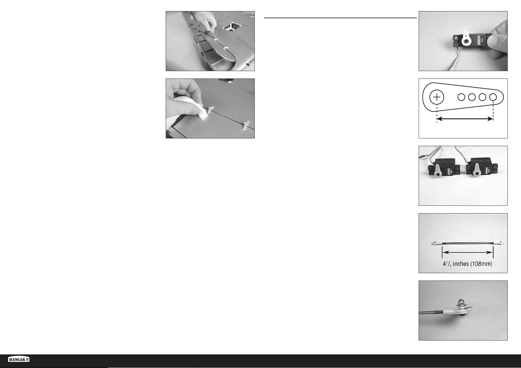
11. Fit the fl ap to the wing. Check that the fl ap can move freely, and the
hinges are all aligned properly. Use low-tack tape to hold the fl ap in
position until the epoxy fully cures.
FLAP SERVO INSTALLATION
1. Center the fl ap servo. Attach the servo horn on the servo
perpendicular to the servo centerline.
We recommend setting the throws to 0% for radios
using a three-position switch to prevent damaging the
servo if the linkage is not the correct length.
12. Use a paper towel and isopropyl alcohol to remove any excess epoxy
before it can fully cure. Use care not to get epoxy in the moving part
of the hinge or between the fl ap and wing. Continue once the epoxy
has fully cured for both sets of fl ap hinges.
Make sure to check that the flap hinges are glued
securely once the adhesive has fully cured.
Repeat this section for the remaining flap hinge installation.
2. When attaching the linkage to the aileron servo arm, use the hole in
the arm that is 5/8-inch (16mm) from the center of the arm.
3. Prepare both the left and right fl ap servos at this time.
4. Assemble the linkage for the fl ap using two ball ends and the 423/32
inch (120mm) threaded rod. Thread each ball end 12 turns on
the link. Adjust the length so the distance between the ball ends
measures 4
1
/4 inches (108mm).
5/8 inch
(16mm)
Ki-43 Oscar 60cc ARF
5. Remove the servo arm from the servo. Secure the servo ball link
to the servo arm using an M3 x 10 button head screw, M3 washer
and M3 lock nut. Use a 2.5mm hex wrench and 5.5mm nut driver to
tighten the hardware.
15 EN
Page 16
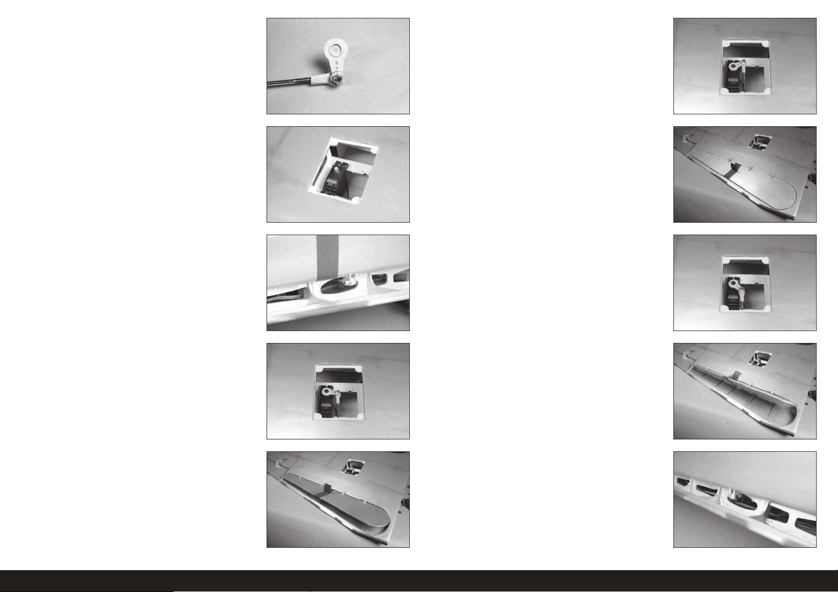
6. The ball link will be attached to the underside of the servo arm as
shown.
7. Install the fl ap servo in the wing with the output facing the leading
edge. Make sure to prepare the servo mounting holes by threading
a servo mounting screw into each hole and removing them. Harden
the mounting screw locations with thin CA before installing the
servo.
The flap servos can be positioned in the wing to allow the
use of a Y-harness to connect the servos to the receiver.
11. Move the servo to the UP fl ap position using the radio system. Adjust
the throws at the radio system to bring the fl ap in alignment with the
bottom of the wing.
8. Secure the servo ball link to the control horn using an M3 x 10
button head screw, M3 washer and M3 lock nut. Use a 2.5mm hex
wrench and 5.5mm nut driver to tighten the hardware.
9. Attach the servo arm to the servo.
10. Adjust the length of the linkage to position the fl ap in the mid fl ap
position of 1–
Remember to set the throws to 0% in both the up and down
positions to prevent damage to the servo, flap or linkage.
13/16 inches (25–30mm).
12. Move the servo to the FULL fl ap position of
(50–60mm) using the radio system. Adjust the throws in the radio
system to obtain the measurements listed.
13. The linkage may rub against the wing structure depending on servo
selection. Use a hobby knife with a #11 blade or a rotary tool and
sanding drum to trim the wing structure as necessary to clear the
linkage.
131/32–23/8 inches
16EN
Page 17
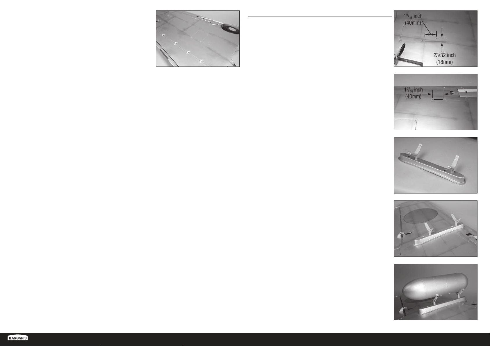
14. Use the steps outlined for the retract cover to install the fl ap cover.
Repeat this section for the remaining flap servo installation.
DROP TANK INSTALLATION
1. Run your fi nger along the bottom of the wing to locate the blind nuts
for the drop tank mount. Use a hobby knife and #11 blade to remove
the covering, exposing the blind nuts.
Thread a screw into the blind nuts by hand first to make sure the
threads are clear. Cross threading, stripping, or damaging the blind
nuts withing the wing will require considerable work to rectify.
2. Thread the drop tank mounts into the blind nuts in the pylons. Do not
over-tighten the mounts and damage the pylon.
Ki-43 Oscar 60cc ARF
3. Attach the pylon to the wing using two M4 x 15 socket head cap
screws and two M4 lock washers. Use a 3mm hex wrench to tighten
the screws.
Place a drop of canopy glue on each screw before
their installation. This will keep them from vibrating
loose yet leave them easily removable.
4. Attach the drop tank to the mounts using four M3 x 12 button head
screws. Use a 2mm hex wrench to tighten the screws.
Place a drop of canopy glue on each screw before
their installation. This will keep them from vibrating
loose yet leave them easily removable.
Repeat this section for the remaining
17 EN
drop tank installation.
Page 18
STABILIZER INSTALLATION
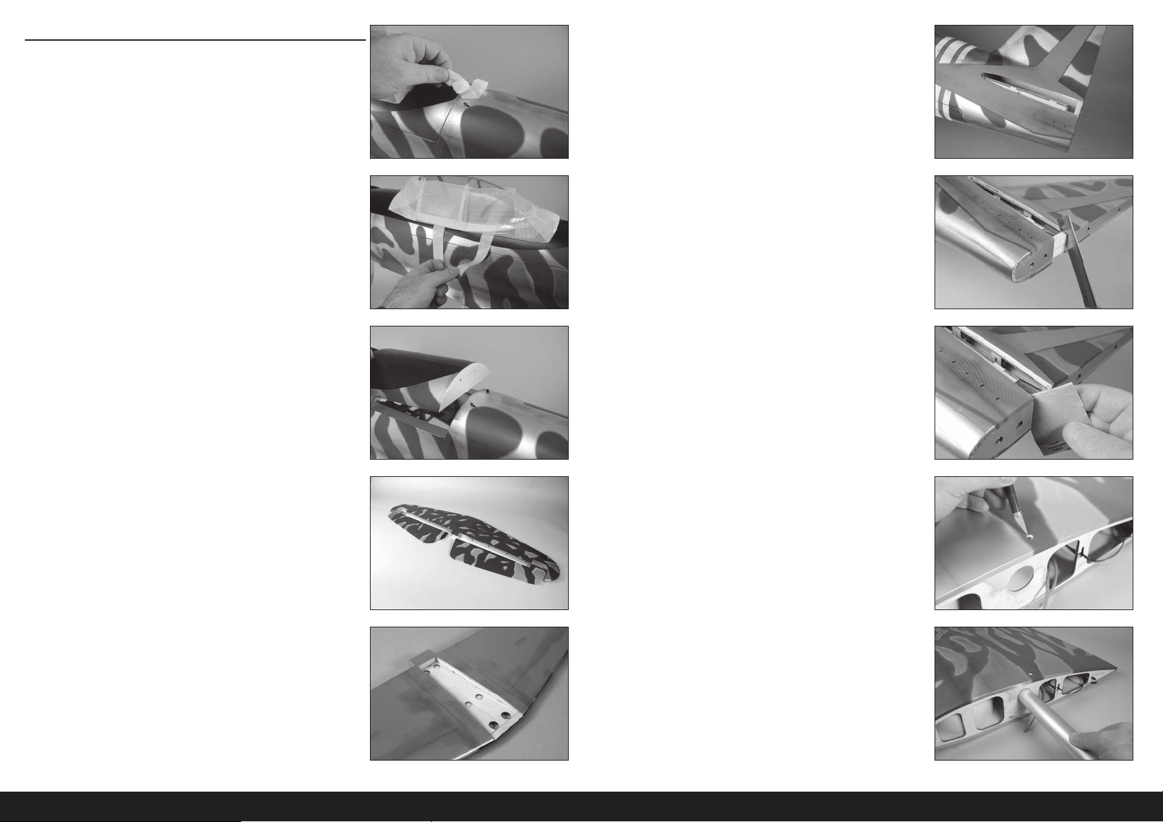
1. Remove the tape and packing materials from the fuselage.
5. Run your fi nger along the sides of the fuselage to locate the opening
for the stabilizer. Use a hobby knife and #11 blade to remove the
covering from the fuselage.
6. Use a razor saw to remove the section of the tail post from the
stabilizer slot.
The tail post is left in position at the factory to prevent damage
and maintain the structural integrity of the fuselage during
shipping and must be removed to install the stabilizer.
2. Move the canopy latch toward the front of the fuselage. Lift the
canopy hatch from the fuselage at the rear and remove it from the
fuselage. Set it aside in a safe location.
3. Separate the elevators from the stabilizer. 8. Run your fi nger along the top of the wing to locate the blind nut
4. Run your fi nger along the bottom of the stabilizer to locate the
center. Use a hobby knife and #11 blade to remove the covering
from the center section.
7. Use medium grit sandpaper to sand the fuselage smooth with the
stabilizer slot.
for the wing retaining bolt. Use a hobby knife with a #11 blade to
remove the covering from the wing to expose the blind nut for the
wing retaining bolt.
For additional security, glue can be applied to the blind
nut on the inside of the wing. Epoxy with micro balloons
to thicken it works well for this task. Make sure not to
get any adhesive inside the threads of the blind nut.
9. Slide the wing tube into the wing tube socket.
The wing tube may be a tight fit in the socket. Polishing the
wing tube with fine sand paper or steel wool will help ease
the installation of the wing tube. Do not force the wing tube in
the socket as it can damage the structure inside the wing.
18EN
Page 19
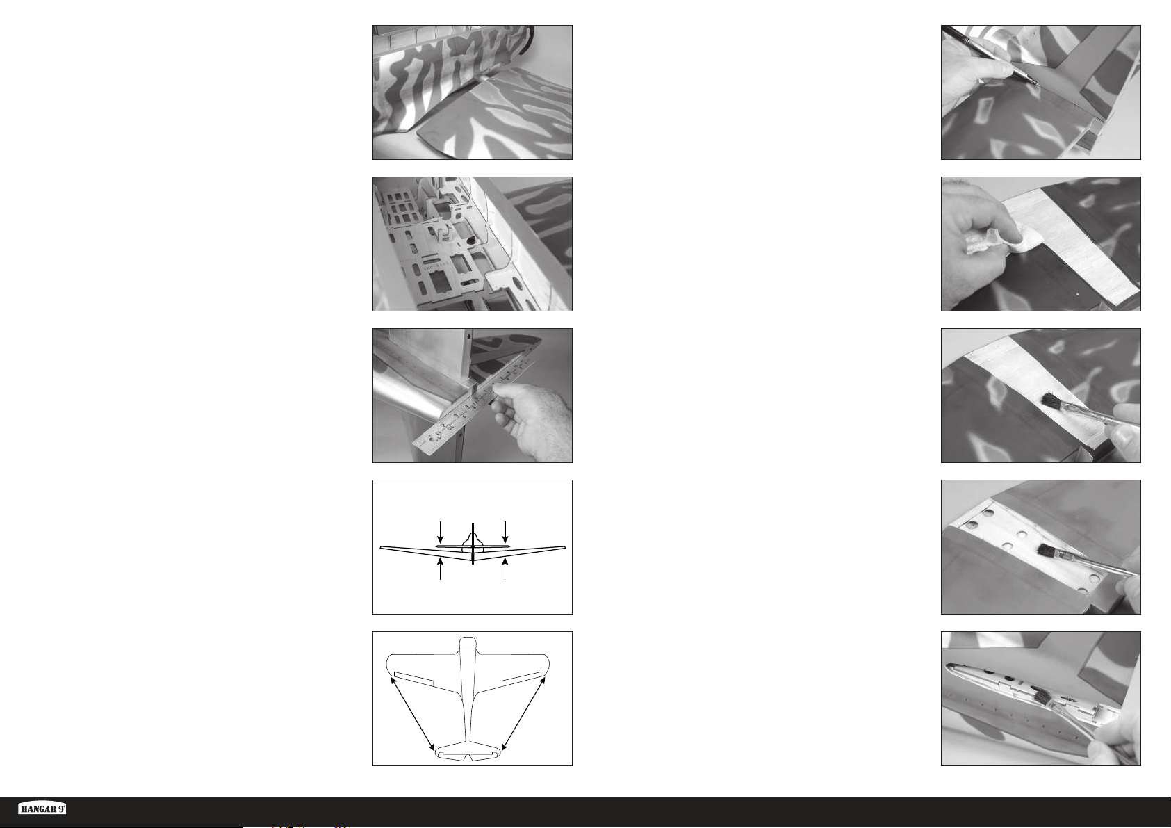
10. Slide the wing panel into position. Guide the fl ap and aileron leads,
as well as the retract air lines, into the fuselage.
15. Use a felt-tipped pen to transfer the fuselage outline onto the top of
the stabilizer.
11. Secure the wing to the fuselage using the 1/4-20 x 1 nylon wing
bolt.
Repeat the steps to secure the remaining
wing panel on the fuselage.
12. Place the stabilizer in position. Use a straight edge to align the rear
of the stabilizer and fi n.
13. Stand back 8-10 feet (2-3 meters) and check that the stabilizer
is aligned with the wing. Lightly sand the stabilizer saddle on the
fuselage to correct any misalignment.
A=A
16. Use a ruler and a hobby knife with a #11 blade to carefully cut the
covering 1/8 inch (3 mm) inside the line drawn on the top of the
stabilizer to remove the covering from the center of the stabilizer.
Use care not to cut into the underlying wood, weakening the
stabilizer.
17. Mix 3/4 ounce (25ml) of 30-minute epoxy. Use an epoxy brush to
apply epoxy to the exposed wood on the top of the stabilizer.
18. Use an epoxy brush to apply epoxy to the exposed wood on the
bottom of the stabilizer as well.
14. Measure from each wing tip to each stabilizer tip. Adjust the
stabilizer so the measurements are the same for both sides.
Ki-43 Oscar 60cc ARF
AA
19. Use an epoxy brush to apply epoxy to the stabilizer mounting surface
for the stabilizer. Position the stabilizer back on the fuselage and
check its alignment. Use a paper towel and a small amount of
isopropyl alcohol to remove any excess epoxy from the fuselage and
stabilizer before the epoxy fully cures. Allow the epoxy to fully cure
AA
A=A
before proceeding.
Check the position of the stabilizer repeatedly during
the curing process to make sure it has not moved.
19 EN
Page 20
ELEVATOR INSTALLATION
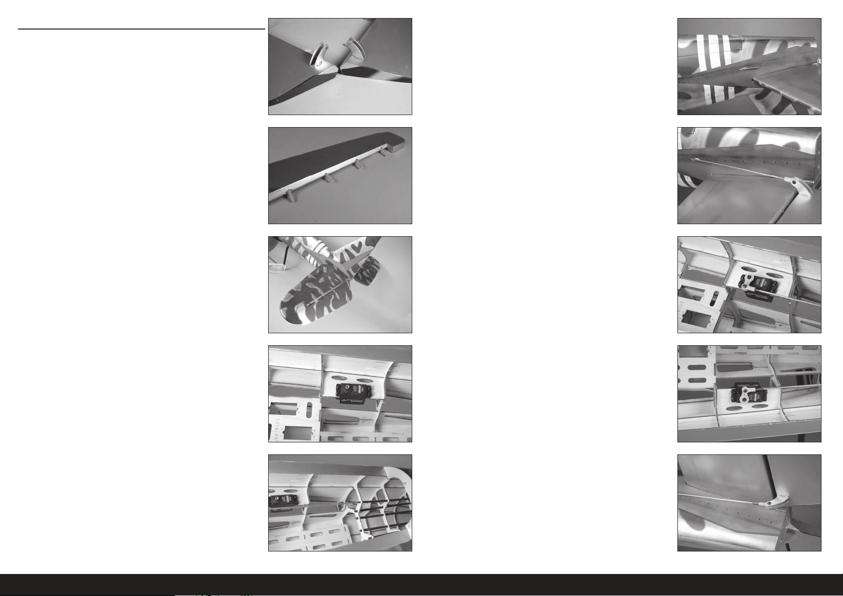
1. Install the elevator control horns. Their installation is the same as the
aileron control horns.
Make sure to check that the control horns are
securely glued before proceeding.
6. Use a hobby knife with a #11 blade to trim the covering so the
pushrod can exit the fuselage.
2. Glue the hinges in the elevator using 30-minute epoxy. The
installation of the elevator hinges is similar to the aileron hinges. Use
the short hinges to hinge the elevators
3. Glue the hinges to the stabilizer using 30-minute epoxy.
Make sure to check that the elevator hinges are glued
securely once the adhesive has fully cured.
4. Prepare the holes in the fuselage for the elevator servo by threading
a screw into each hole. Remove the screws and place 2 to 3 drops
of thin CA in each hole to harden the surrounding wood. Once the CA
has fully cured, install the elevator servo with the servo output shaft
toward the front of the fuselage.
7. Thread a ball end 12 turns on the pushrod. Secure the servo ball
link to the control horn using an M3 x 10 button head screw, M3
washer and M3 lock nut. Use a 2.5mm hex wrench and 5.5mm nut
driver to tighten the hardware.
8. Center the elevator servo using the radio system. Attach the servo
horn on the servo perpendicular to the pushrod. Thread a ball end
12 turns on the pushrod. Secure the servo ball link to the control
horn using an M3 x 10 button head screw, M3 washer and M3 lock
nut. Use a 2.5mm hex wrench and 5.5mm nut driver to tighten the
hardware.
9. Repeat the previous steps to install the remaining elevator servo and
pushrod.
5. Slide a 36
5
/8 inch (930mm) pushrod into the pushrod tube.
20EN
Page 21
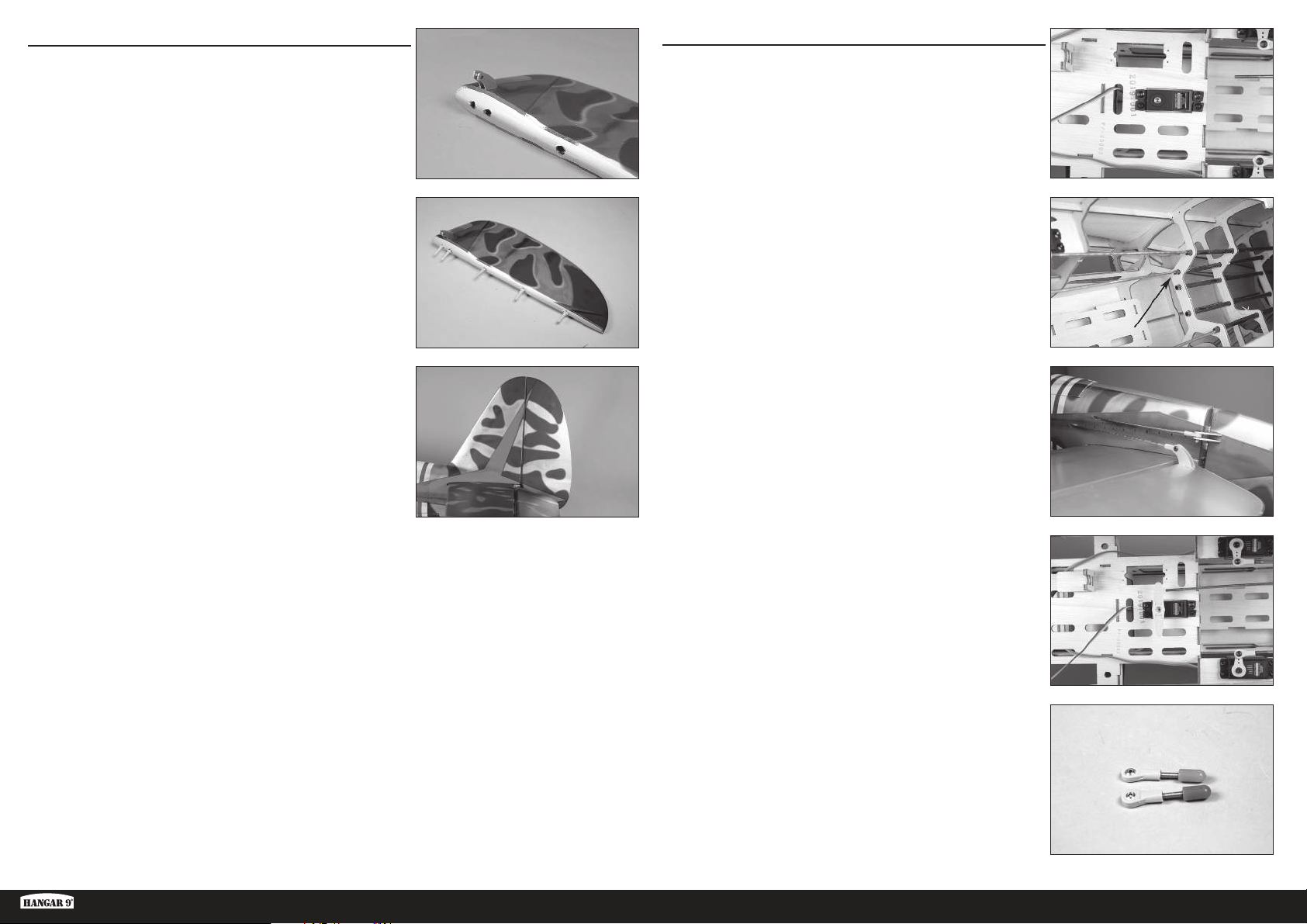
RUDDER INSTALLATION
RUDDER LINKAGE INSTALLATION
1. Install the rudder control horns. Their installation is the same as the
aileron control horns. Make sure to install the rudder control horns
on the correct side of the rudder.
Make sure to check that the rudder control horns are
glued securely once the adhesive has fully cured.
2. Glue the hinges in the rudder using 30-minute epoxy. The installation
of the rudder hinges is similar to the aileron hinges.
3. Glue the hinges to the fi n using 30-minute epoxy.
Make sure to check that the rudder hinges are glued
securely once the adhesive has fully cured.
1. Prepare the holes in the fuselage for the rudder servo by threading a
screw into each hole. Remove the screws and place 2 to 3 drops of
thin CA in each hole to harden the surrounding wood. Once the CA
has fully cured, install the rudder servo with the servo shaft toward
the front of the fuselage.
1
2. Slide a 40
3. Thread a ball end 12 turns on the pushrod. Secure the servo ball link
to the control horn using an M3 x 10 button head screw, M3 washer
and M3 lock nut. Use a 2.5mm hex wrench and 5.5mm nut driver to
tighten the hardware.
/8 inch (1020mm) pushrod into the rudder pushrod tube.
Ki-43 Oscar 60cc ARF
4. Center the rudder servo using the radio system. Place the servo
arm on the servo so it is perpendicular to the servo centerline.
It may be necessary to rotate the arm 180-degrees to achieve a
better alignment of the arm on the servo. Mark the arm so it can be
returned to its position on the servo.
5. Thread a ball end 12 turns on a cable fi tting. Prepare two cable
fi ttings at this time.
21 EN
Page 22
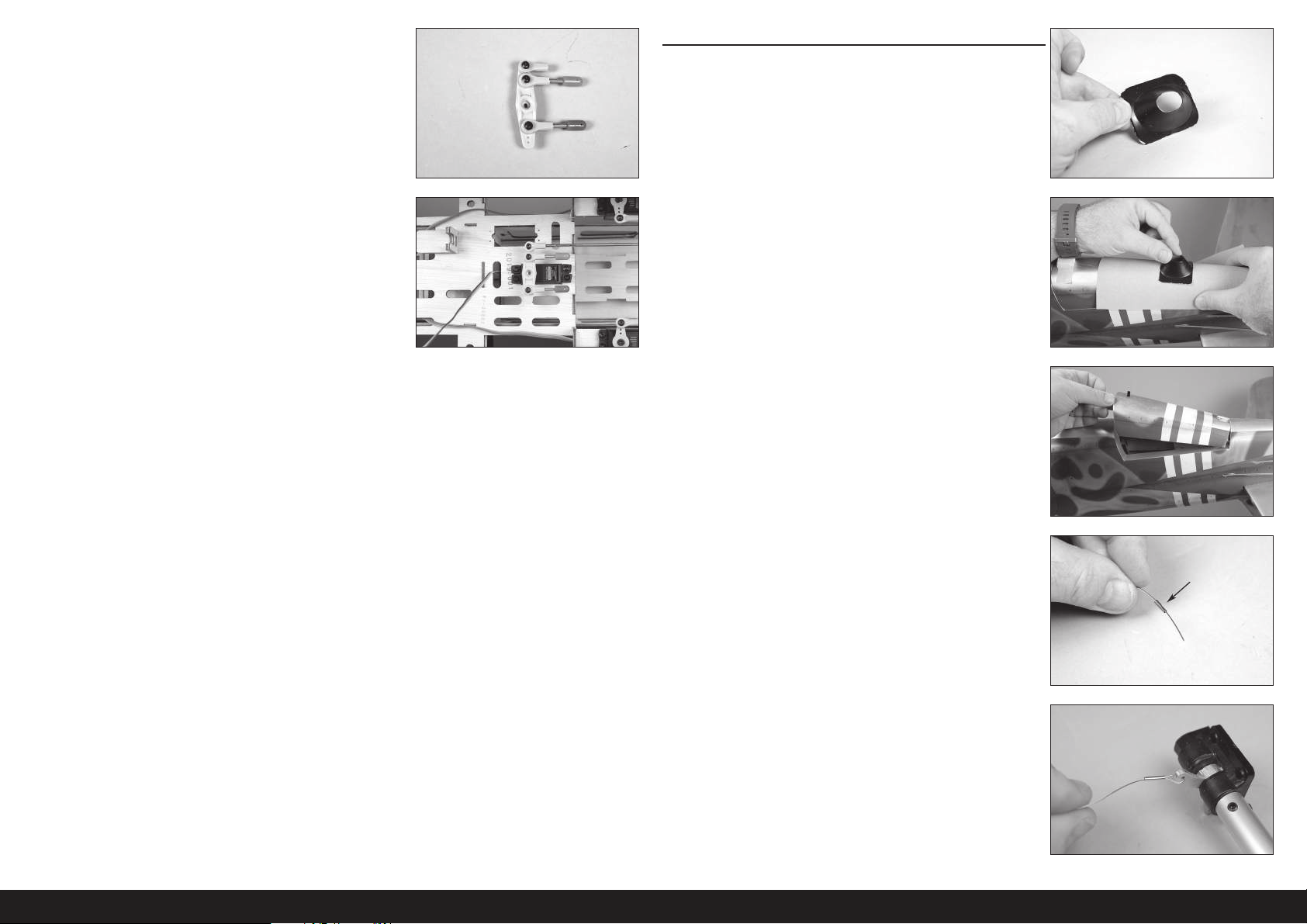
6. Attach a ball end, and the two ball ends with cable fi ttings, to the
rudder servo arm. Use three M3 x 10 button head screws, three
M3 washers and three M3 lock nuts. Use a 2.5mm hex wrench and
5.5mm nut driver to tighten the hardware.
TAIL WHEEL INSTALLATION
1. Use hobby scissors to trim the tail gear fairing.
The installation of the tail gear fairing is optional.
7. Thread the pushrod into the ball end on the servo arm. With the radio
system on, adjust the linkage so the rudder is centered when the
arm is on the servo. Do not install the servo arm screw at this time.
2. Place medium grit sandpaper against the fuselage. Lightly sand the
tail gear fairing to match the shape of the fuselage.
3. Slide the latch toward the rear of the fuselage and remove the tail
gear cover. Set the cover aside.
4. Slide a sleeve on one end of the cable.
5. Pass the cable through the hole in the tail wheel arm. Pass the cable
back through the sleeve.
22EN
Page 23
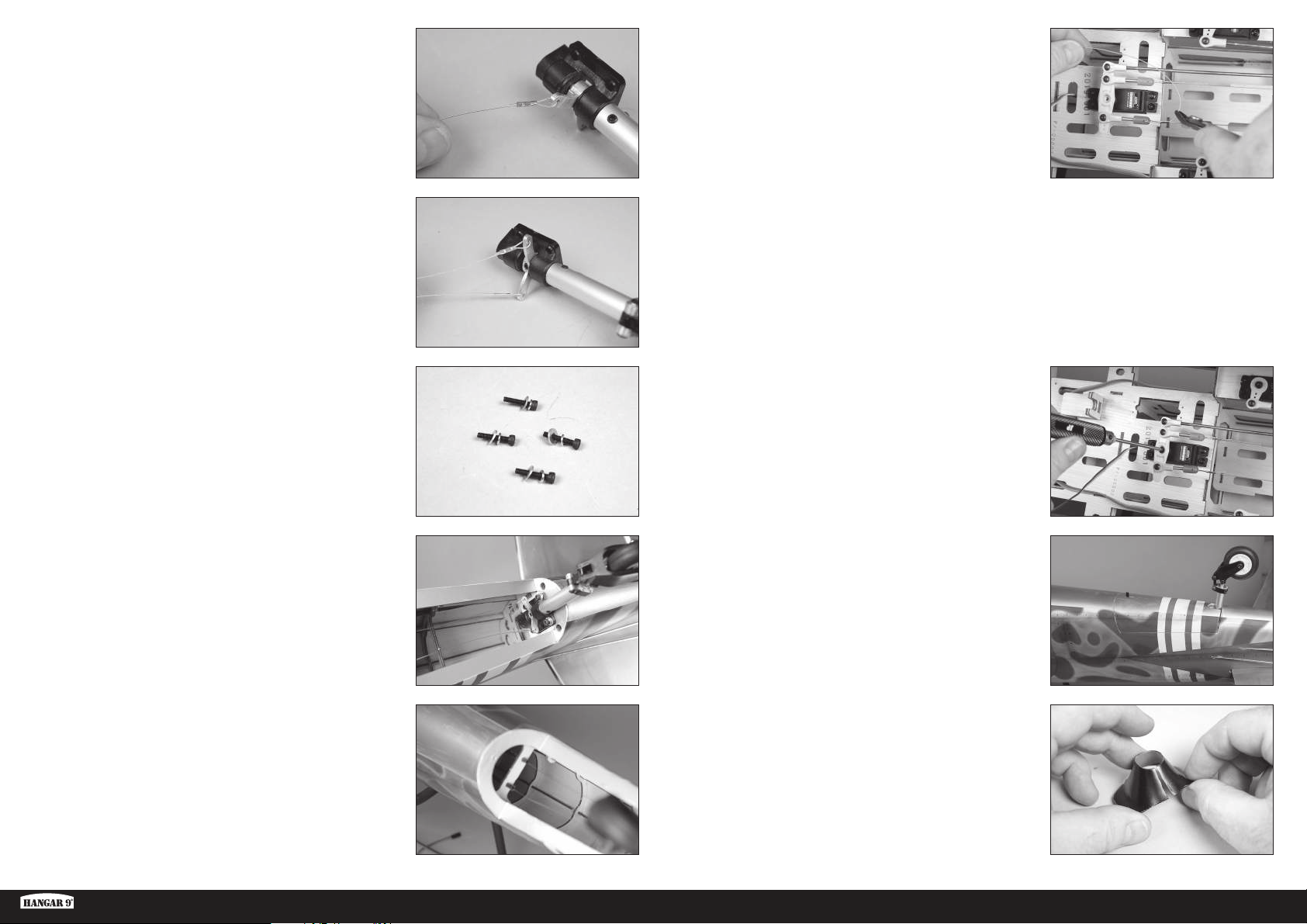
6. Use crimping pliers to secure the sleeve to the cable.
Use caution to not apply excessive pressure and cut
the sleeve instead of securing it to the wire.
11. Slide a sleeve on one end of the cable. Pass the cable through the
hole in the cable fi tting. Pass the cable back through the sleeve. With
the rudder servo and tail wheel centered, apply light tension on the
cable. Use crimping pliers to secure the sleeve to the cable.
The servo arm can be removed from the servo if
necessary. Use caution to not press too hard and cut
the crimp instead of securing it to the wire.
Repeat the process to secure both cables.
7. Repeat the process to secure the remaining cable to the tail wheel
arm.
8. Slide an M3 lock washer, then an M3 washer on an M3 x 15 socket
head cap screw. Prepare all four screws.
9. Place a drop of threadlock on each of the screws. Secure the tail
wheel bracket in the fuselage using the screws from the previous
step and a 2.5mm hex wrench.
The cables may stretch slightly over time. Periodically check
the cables to make sure there is still light tension on them.
Use side cutters to trim any excess cable to prevent it from interfering
with the operation of the model.
12. Secure the rudder servo arm using the screw provided with the
rudder.
13. Place the tail wheel cover back on the fuselage.
10. Slide the cables into the tubes in the fuselage. Retrieve the cables
inside the fuselage.
Ki-43 Oscar 60cc ARF
14. Use hobby scissors to cut a slot in the fairing so it can be placed
over the tail wheel assembly.
23 EN
Page 24
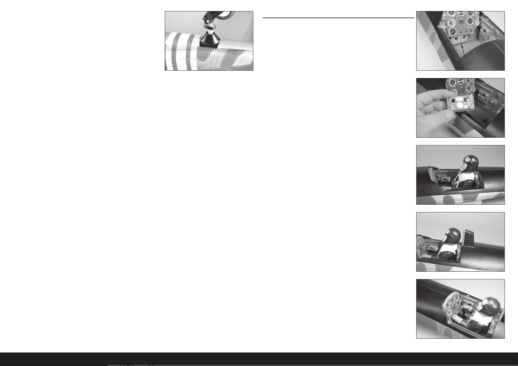
15. Glue the tail wheel fairing to the tail wheel cover using contact
adhesive. Make sure not to glue the cover to the fuselage in case the
cover requires removal to access the tail gear.
PILOT AND CANOPY INSTALLATION
1. When fi tting the pilot in the cockpit, the lower portion of the
instrument panel must be removed.
Production models may not need the lower
portion of the instrument panel removed.
2. Carefully remove the lower instrument panel using a hobby knife
and #11 blade.
3. Use contact adhesive to glue the pilot in the cockpit. Allow the
adhesive to fully cure before proceeding.
4. Glue the head rest in position using medium CA or contact adhesive.
5. Glue the control stick in the cockpit using medium CA or 5-minute
epoxy. Position the control stick near the hands of the pilot when a
pilot has been installed.
24EN
Page 25
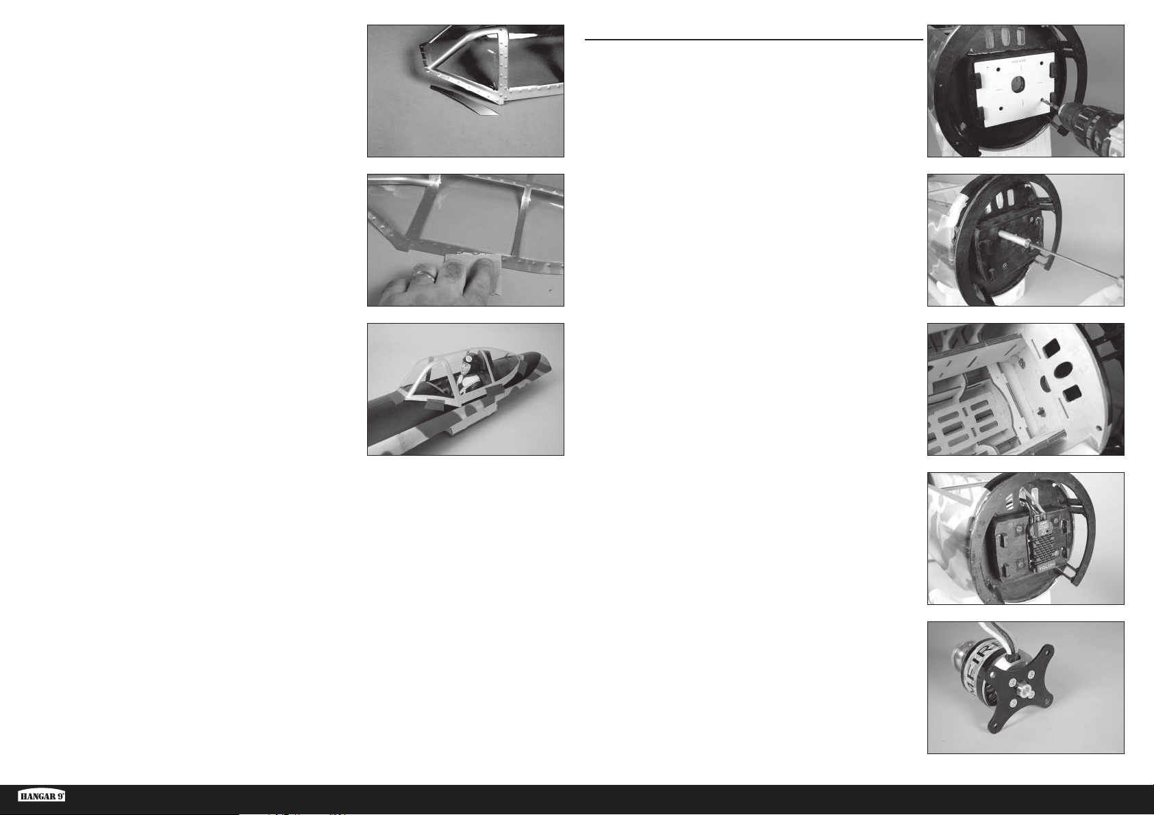
6. It may be necessary to trim excess material from the canopy. Use
hobby scissors to trim the canopy, then use medium grit sandpaper
to smooth the edges.
ELECTRIC MOTOR INSTALLATION
As with many scale warbirds, the Ki-43 Oscar has a short nose
moment. It maybe necessary to add nose weight depending on what
power system is used. Be aware of this when assembling and try
to keep all components as far forward in the fuselage as possible.
7. Use medium-grit sandpaper to lightly sand the inside edge of the
canopy where it contacts the canopy hatch. Clean the sanded area
using a paper towel and isopropyl alcohol to remove any debris or
oils. This provides the surface texture necessary for the adhesive to
bond to.
8. Use canopy glue or contact adhesive to glue the canopy to the
canopy hatch. Use tape to hold the canopy in position until the
adhesive fully cures.
Do not use CA when gluing the canopy. When CA cures, it releases
gases that can fog the canopy and detract from its appearance.
1. Place the mounting template on the fi rewall. Use low-tack tape to
hold the template in position. Use a drill and 1/4-inch (6mm) drill bit
to drill the four holes in the fi rewall to attach the motor.
When using power systems other than the recommended
choices, we advise using the mounting template as a test
to ensure hole alignment before drilling the firewall.
2. Use the screws and standoffs to draw the blind nuts into the fi rewall
from inside the fuselage.
3. Solder any connectors necessary to connect the speed control to
the motor and battery. Secure the speed control to the fi rewall using
screws or tie wraps.
Ki-43 Oscar 60cc ARF
4. Attach the mount to the motor using the hardware included with the
motor. Use a drop of threadlock on each screw to prevent them from
vibrating loose.
25 EN
Page 26
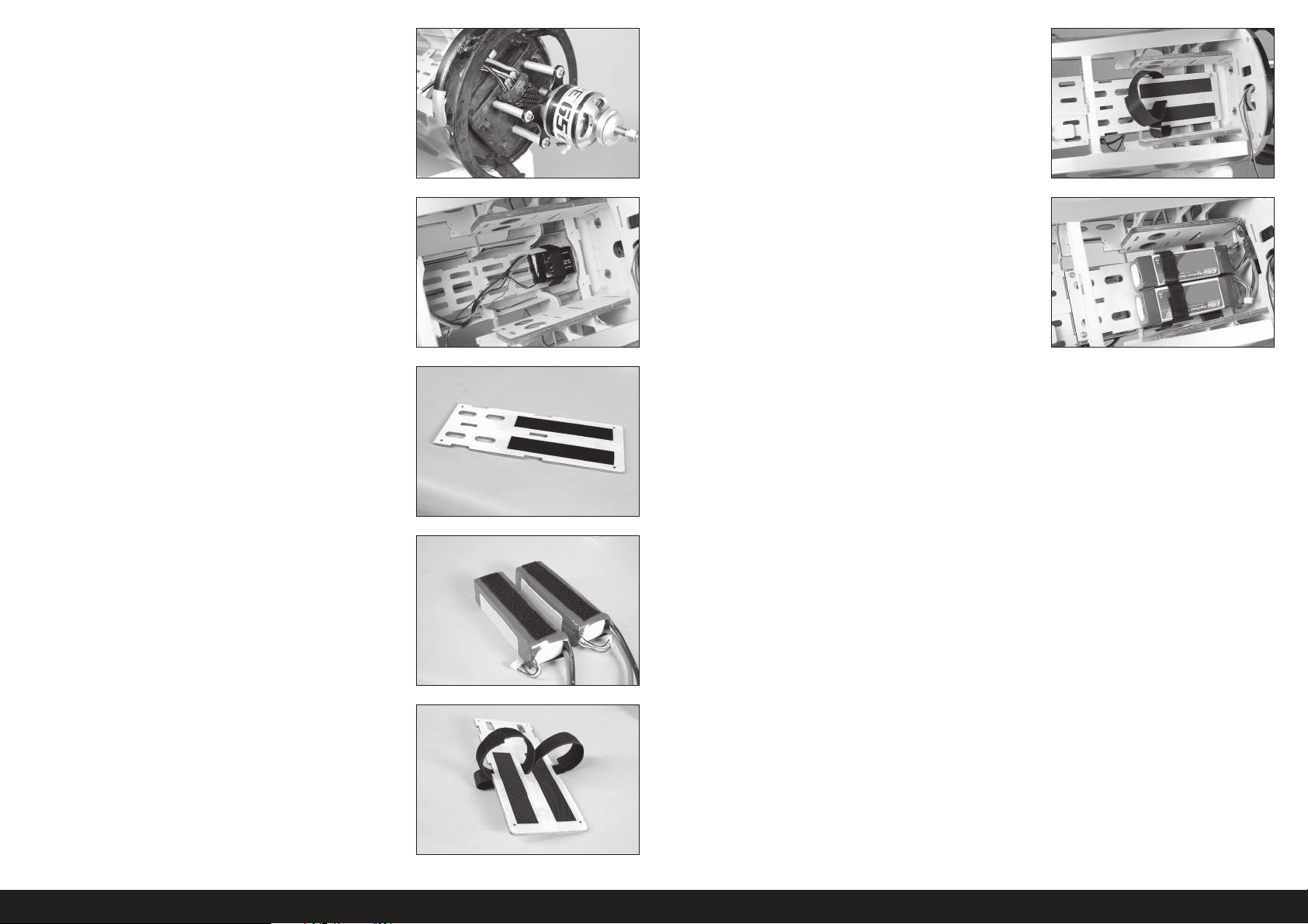
5. Attach your motor to the fi rewall using the aluminum standoffs
and screws. Use a drop of threadlock on each screw to prevent
them from vibrating loose. Connect the leads between the speed
control and motor. Secure the leads so they don’t interfere with the
operation of the motor.
10. Prepare and harden the holes in the fuselage for the battery tray
screws using an M3 x 15 sheet metal screw and thin CA. Secure the
battery tray in the fuselage using four M3 x 15 sheet metal screws
and four M3 washers.
6. Secure the battery for the radio system in the lower section of the
fuselage. Use hook and loop tape and hook and loop straps to keep
the battery secure.
7. Apply a thin layer of 5-minute epoxy to the battery tray where the
hook and loop will be attached. Allow the epoxy to fully cure before
applying hook and loop tape to the battery tray.
The adhesive on the hook and loop tape will not
adhere to the raw wood. Using epoxy creates a
surface suitable for the hook and loop adhesive.
8. Apply the mating hook and loop tape to the batteries.
Do not cover safety warnings on the
battery with hook and loop tape.
11. Secure the batteries in the fuselage using the hook and loop straps.
The position of the batteries can be moved to help balance the
model.
9. Use hook and loop straps around the battery tray to secure the
batteries to the tray.
Apply a small amount of 5-minute epoxy to the straps to
secure them to the battery tray. This will prevent them from
falling through the holes when the battery is removed.
26EN
Page 27
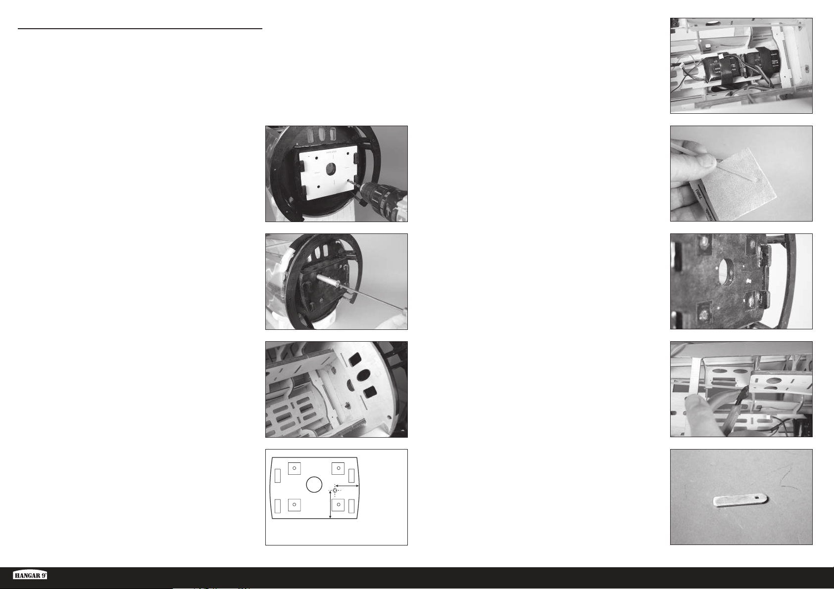
GAS ENGINE INSTALLATION
As with many scale warbirds, the Ki-43 Oscar has a short nose
moment. It maybe necessary to add nose weight depending on what
power system is used. Be aware of this when assembling and try
to keep all components as far forward in the fuselage as possible.
4. Secure the batteries for the radio system and ignition in the lower
section of the fuselage. Use hook and loop tape and hook and loop
straps to keep the batteries secure.
1. Place the mounting template on the fi rewall. Use low-tack tape to
hold the template in position. Use a drill and 1/4-inch (6mm) drill bit
to drill the four holes in the fi rewall to attach the motor.
When using power systems other than the recommended
choices, we advise using the mounting template as a test
to ensure hole alignment before drilling the firewall.
2. Use the screws and standoffs to draw the blind nuts into the fi rewall
from inside the fuselage.
5. Use medium grit sandpaper to lightly sand the pushrod tube.
Remove any oils or debris from the tube using a paper towel and
isopropyl alcohol.
6. Slide the tube into the hole in the fi rewall. Leave 1/4 inch (6mm) of
the tube protruding from the fi rewall. Use medium CA to glue the
tube in place.
7. Use side cutters to trim the pushrod tube 3/16 inch (5mm) behind
the edge of the inner fuselage side.
3. Use a drill and 9/64-inch (3.5mm) drill bit to drill the hole for the
throttle pushrod.
The location shown is for the Evolution 62GX. Make sure to
properly locate the throttle tube when using other engines.
Ki-43 Oscar 60cc ARF
23/32 inches
(53mm)
121/32 inches
(42mm)
8. Use a drill and 9/64-inch (3.5mm) drill bit to drill a hole in a mixing
stick. Cut the stick to a length of 1
1
/2 inches (38mm). This will be the
rear support for the throttle pushrod tube.
27 EN
Page 28
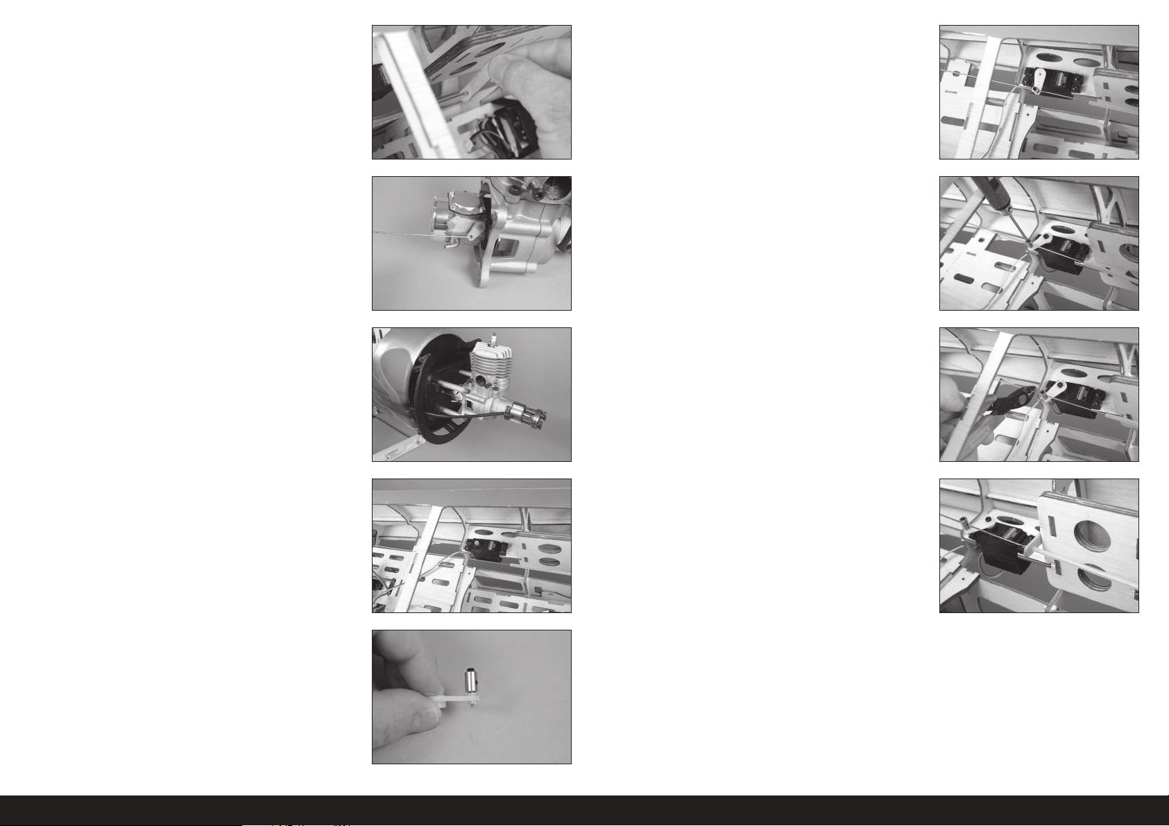
9. Slide the support on the pushrod tube. 14. Center the servo using the radio system and install the servo arm on
the servo perpendicular to the servo center line. Make sure to slide
the connector on the pushrod wire. Use side cutters to remove any
arms that may interfere with the operation of the servo.
10. Connect the Z-bend in the pushrod to the carburetor arm. 15. Move the carburetor and servo to the low-throttle position and
tighten the setscrew securing the pushrod to the connector at the
servo. Use side cutters to trim the excess wire. Check the operation
of the carburetor using the radio system. Make any adjustments
necessary to fully open and close the carburetor using the radio
system.
11. Guide the throttle pushrod into the pushrod tube. Attach the engine
to the fi rewall using four spacers, four machine screws, and four
washers. Apply a drop of threadlock on the end of each screw before
installation.
12. Prepare the holes in the fuselage for the throttle servo by threading
a screw into each hole. Remove the screws and place 2 to 3 drops
of thin CA in each hole to harden the surrounding wood. Once the CA
has fully cured, install the throttle servo with the servo shaft toward
the rear of the fuselage.
13. Mount the throttle servo connector in the throttle servo arm so it is
7/16-inch (11mm) from the center of the servo arm. Place a drop
of canopy glue on the M2 nut, then install it on the underside of the
arm to secure the connector.
16. Use side cutters to remove any excess pushrod wire that may
interfere with the operation of the throttle servo.
17. Use 15-minute epoxy to glue the pushrod tube support to the rear
edge of the inner fuselage side.
28EN
Page 29
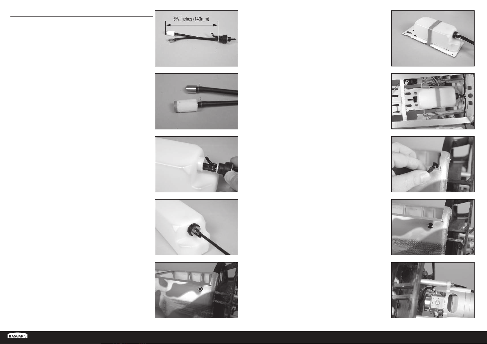
FUEL TANK INSTALLATION
1. Cut a piece of fuel tubing that will result in the end of the clunk
being 55/8 inches (143mm) from the back of the aluminum plate.
6. Secure the fuel tank to the fuel tank tray using hook and loop straps
Secure 7
1
/2 inch ((190mm) pieces of fuel line to the three lines
exiting the tank. Use tie wraps to prevent the lines from sliding
loose.
2. Secure the tubing to the clunk and stopper using thin wire. This will
keep the tubing from sliding loose inside the tank. Make sure to use
the clunk supplied with your engine.
A second clunk can be installed to provide
a line to fuel/de-fuel your aircraft.
We recommend using a clunk with a filter for all engine installations.
3. Insert the clunks into the tank. Install the larger clunk, then the small
clunk. The vent line will angle toward the top of the fuel tank.
4. Mark the lines from the tank so the fuel lines can be identifi ed from
outside the tank. Tighten the screw in the stopper using a #1 Phillips
screwdriver.
Check that both clunks can move freely inside the tank.
If not, adjust the tubing from outside the tank so they can
move freely to ensure consistent fuel flow to the engine.
7. Prepare and harden the holes in the fuselage for the fuel tank tray
screws using an M3 x 15 sheet metal screw and thin CA. Secure the
fuel tank tray in the fuselage using four M3 x 15 sheet metal screws
and four M3 washers.
8. Pass the fi ll line through the fi tting in the fuselage. Insert the fi ll plug
in the fi ll line from the tank.
9. Press the plug into the fi tting to secure the fi ll line. Route the vent
line from the tank to the bottom of the fuselage. Use a fi tting at the
underneath the fuselage to secure the vent line.
5. Use a hobby knife with a #11 blade to remove the covering from the
fuselage for the fi ll line fi tting. Install the fi tting in the fuselage.
The fill line can also be left inside the fuselage to retain
the scale look of the model. The removal of the canopy
hatch will be required to add fuel to the fuel tank.
Ki-43 Oscar 60cc ARF
10. Connect the line from the fi ltered clunk to the carburetor. Use a tie
wrap to secure the line to the carburetor.
Use a filter between the fuel tank and carburetor
to avoid the potential of debris that could be in the
fuel from entering the carburetor and engine.
29 EN
Page 30
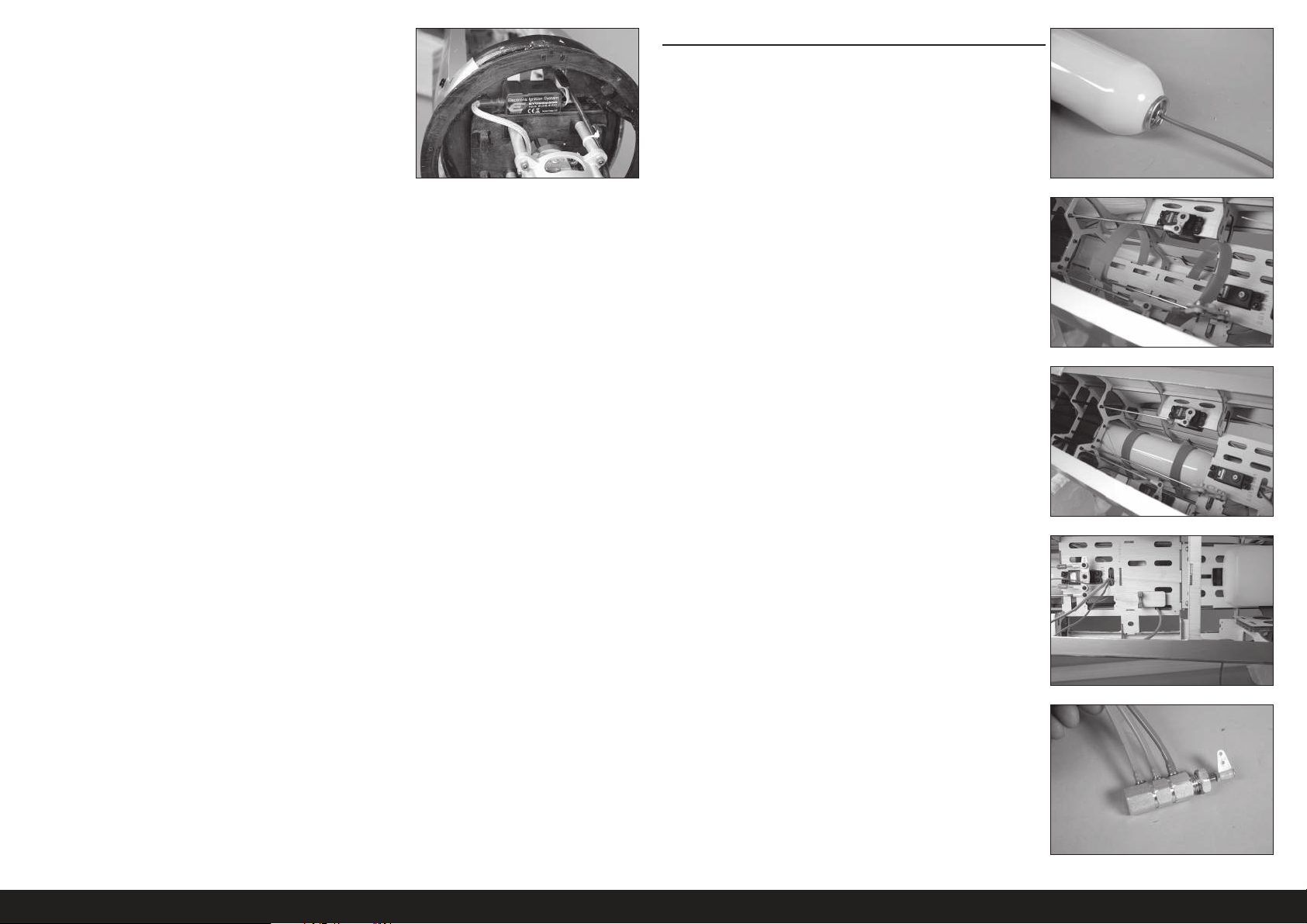
11. Mount the ignition module to the fi rewall. Use the instructions
provided with the engine to connect the module to the engine and
ignition battery.
RETRACT AIR SYSTEM INSTALLATION
1. Cut a 12-inch (305mm) piece of air line and attach it to the air tank.
Use a heat gun on low to soften the air lines
slightly so they will slide on the fittings.
2. Remove the servo arm from the rudder servo. Place straps around
the tank in the fuselage.
3. Apply a small amount of contact adhesive on the tray. Use the straps
to secure the air tank in the fuselage.
4. Route the air line under the servo tray to the location for the air
valve.
5. Cut two 4 inch (102mm) pieces of orange air line and one 4 inch
(102mm) piece of blue air line. Attach the orange air lines to the
fi tting near the end and center fi ttings of the air valve, and the blue
air line to the fi tting near the actuator.
Do not remove the actuator from the valve body as it will
damage the O-rings and cause an air leak in the valve.
Use a heat gun on low to soften the air lines
slightly so they will slide on the fittings.
30EN
Page 31
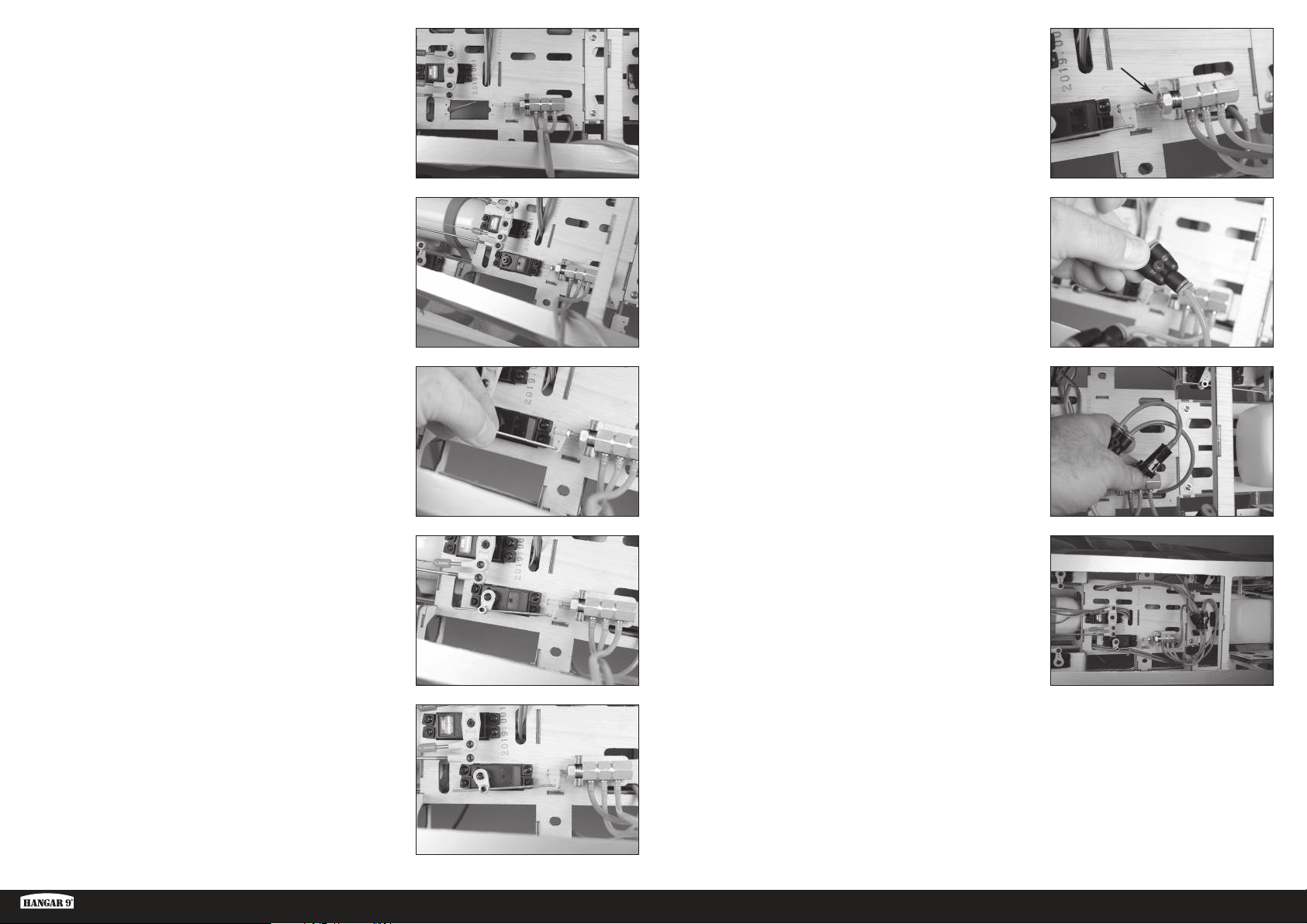
6. Secure the air valve in the fuselage. Use a 14mm wrench to tighten
the nut, securing the valve in place.
11. Toggle the switch at the radio and slowly increase the throw until
the edge of the actuator is fl ush with the edge of the valve body.
Make sure not to pull the actuator out of the
valve body and damage the O-rings.
7. Prepare the holes in the fuselage for the retract valve servo by
threading a screw into each hole. Remove the screws and place 2
to 3 drops of thin CA in each hole to harden the surrounding wood.
Once the CA has fully cured, install the retract valve servo with the
servo shaft toward the rear of the fuselage.
8. Insert the Z-bend of the retract valve pushrod through the hole in the
actuator.
9. Mount the servo connector in the servo arm so it is 11/32-inch
(9mm) from the center of the servo arm. Place a drop of canopy glue
on the M2 nut, then install it on the underside of the arm to secure
the connector. Set the throws for the retract servo to 0% in both
directions. Center the actuator as close to center as possible, then
tighten the setscrew securing the pushrod in the connector.
12. Connect a Y fi tting to the tube from the center of the valve. Fully
press the air line into the fi tting.
The air lines can be removed by pressing the shoulder against
the body of the fitting and pulling the air lines free.
13. Cut a 2-inch (51mm) piece of air line and connect the fi ll valve. The
arrow will point to the fi tting/valve. Attach the line from the air tank
to the fi tting.
The arrow indicates the flow of air from the external fill pump into
the retract system. There is a check valve inside the valve that
stops air from flowing the other way and emptying the air tank.
14. Connect the remaining Y fi ttings for the up and down air lines. Use
air line colors that match those from the valve to differentiate the
operation of the retracts. Route the air lines in the fuselage along
the edges of the radio tray toward the openings for the wing. Secure
all the air lines and fi ttings in the fuselage. Add fi ttings at the ends
of the air lines to connect the air lines from the retracts in the wing
panels.
It does not require much throw to operate the valve. Make sure
not to damage the valve using too much throw at the servo.
10. Slowly increase the servo throw at the radio system to move the
actuator into the valve. Make sure not to bottom out the actuator and
damage the valve.
Ki-43 Oscar 60cc ARF
With the push-in type pneumatic connectors it is important to
make sure the air line is pushed all the way into the air connectors
to seal the air lines. Failure to do so will result in air leaks.
31 EN
Page 32
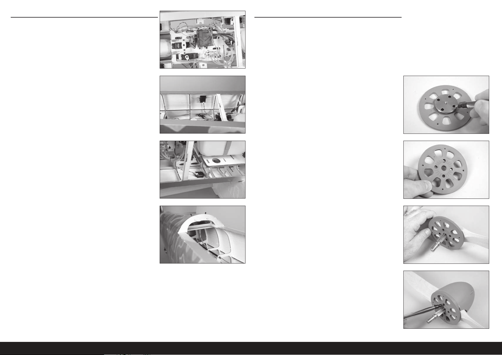
RECEIVER INSTALLATION
COWLING AND SPINNER INSTALLATION
1. Install the receiver in the fuselage. Secure the receiver using the
methods included in the receiver or radio instructions.
2. Mount any remote receivers in the fuselage using hook and loop
tape. Use the instructions provided with the receiver to orient the
remote receivers in the fuselage for the optimum operation of the
receiver.
Apply a small amount of 5-minute epoxy to the hook
and loop tape to secure them in the fuselage.
The spinner cone has been prepared with the slots for the propeller.
Most engines of this size use four bolts to retain the propeller.
Careful positioning of the drilled holes is required to make sure
the propeller aligns with the cutouts in the spinner cone.
We recommend preparing at least two propellers in case
a new propeller is required when out flying the model.
1. Place the washer from the engine on the spinner backplate. Mark
the locations for the propeller mounting screws using a felt-tipped
pen.
2. Remove the washer from the backplate. Use a drill and 7/32-inch
(5mm) drill bit to drill the holes for the propeller mounting screws.
A drill press is highly recommended for drilling
the holes to guarantee the holes are properly
aligned when installing the propeller.
3. Use a stepped reamer or bolt through the spinner back plate and
propeller to hold them in alignment so the bolt holes for attaching
the propeller can be marked.
4. Use the four M3 x 10 socket head cap screws to secure the spinner
cone to the back plate. Use a 3mm hex wrench to tighten the
screws. Position the propeller so it does not contact the spinner
cone. Use a pin vise and 3/16-inch (4.5mm) drill bit to drill and
indent or marker for the mounting bolt locations.
It may be necessary to trim the spinner cone to clear
the propeller depending on the choice of propellers.
32EN
Page 33
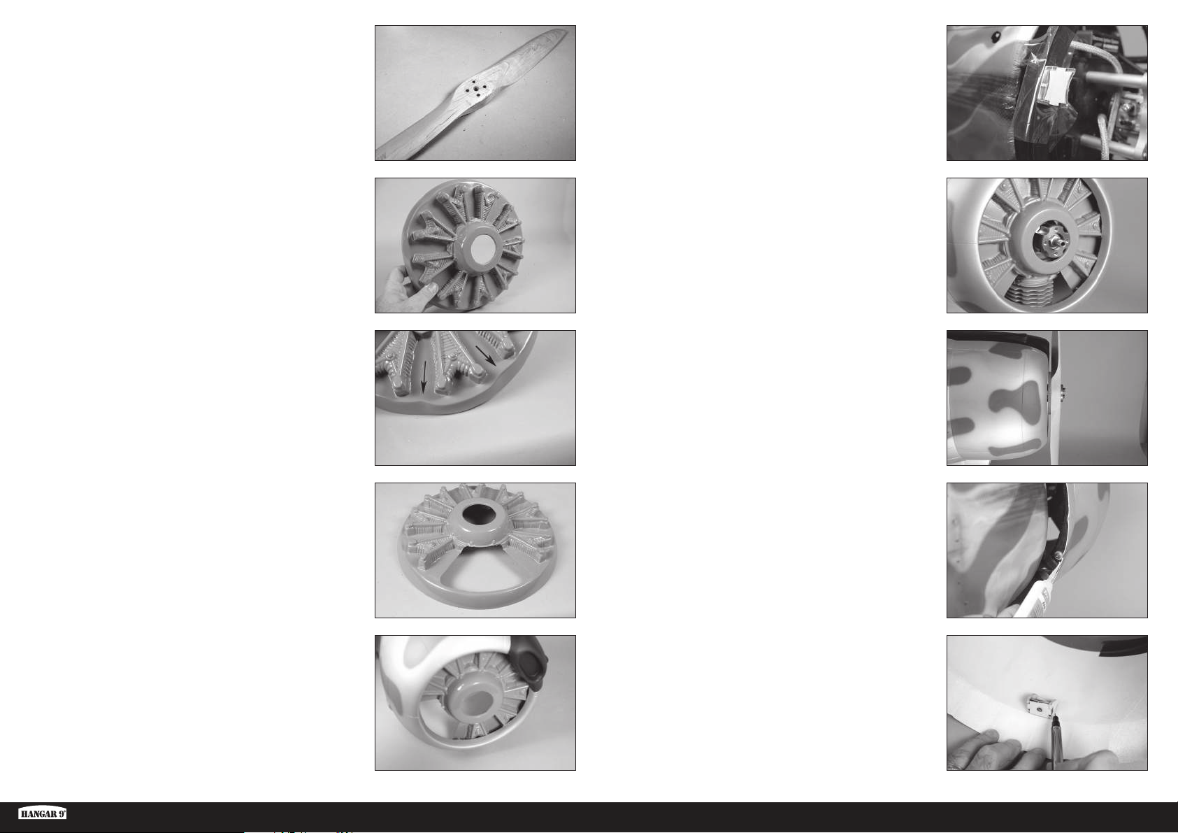
5. Disassemble the spinner and remove the propeller. Use a drill and
7/32-inch (5mm) drill bit to drill the holes in the propeller for the
mounting screws.
A drill press is highly recommended for drilling
the holes to guarantee the holes are properly
aligned when installing the propeller.
10. Place a piece of clear plastic between the cowl mounts and the cowl
ring. Secure the cowl mounts to the fuselage using the M4 x 15
socket head cap screws, M4 lock washer and M4 washer. Align the
mount with the cowl ring and tighten the hardware using a 3mm hex
wrench.
6. Remove the material in the center of the dummy radial for the
propeller shaft and drive washer for your particular motor.
The dummy engine is supplied unpainted. It is functional as an air
baffle which helps direct air over the gas engines cylinder head.
Failure to fit the dummy engine may result in your gas engine
overheating due to poor airflow through the cowling vents.
7. The top of the radial engine is indicated by two indentations that will
align with the gun exits in the cowling. Use this as a reference when
trimming the engine.
8. Gas: Trim the dummy radial engine to allow air to pass over the
engine and to clear the carburetor if necessary.
EP: Trim the material between the cylinders of the dummy radial
engine to allow cooling air to pass across the motor and ESC.
The photo shows the radial engine prepared
for the gas engine installation.
11. Slide the cowling into position. Center the drive washer in the
opening.
12. Attach the propeller to the motor shaft using the hardware included
with the engine. Position the cowling so the propeller is equal
distance from the cowling when rotated.
13. Use thin CA to tack glue the mounts to the cowling.
The mounts will be removed to be glued securely in the following
steps. Do not use excessive amounts of glue in this step.
The dummy radial engine can be detailed using paint before
securing it in the cowling. Make sure to test any paints on the
trimmed pieces to make sure they are compatible with the plastic.
9. Use sandpaper to remove the paint from the dummy radial where
it contacts the inside of the cowling. This will increase the bond of
the adhesive to the dummy radial. Use 15-minute epoxy to glue the
radial engine inside the cowling. Allow the epoxy to fully cure before
proceeding.
Ki-43 Oscar 60cc ARF
14. Carefully remove the screws and cowling from the fuselage. Use a
felt-tipped pen to trace the outline of the mounts on the inside of the
cowling.
33 EN
Page 34
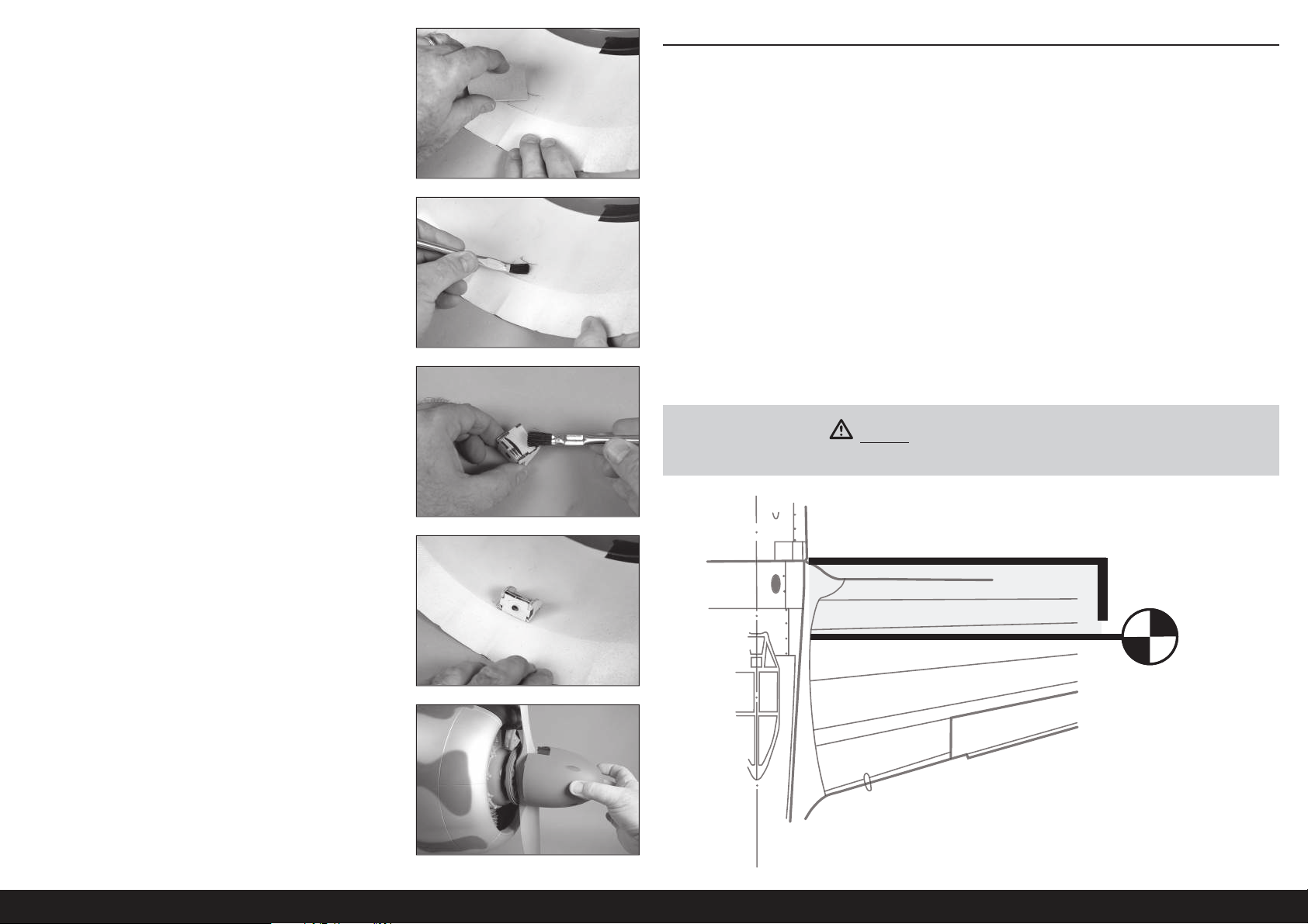
15. Remove the mounts and use medium grit sandpaper to sand the
area inside the cowling where the mounts rest, and an area at least
1/2 inch (13mm) outside of the area marked. Use a paper towel and
isopropyl alcohol to remove any oils or debris from the inside of the
cowling.
Preparation for gluing the mounts is important to guarantee the
adhesive can properly bond the mounts to the inside of the cowling.
16. Mix 1/2 ounce (15ml) of 30-minute epoxy. Apply epoxy inside the
cowling in the areas for the mounts.
CENTER OF GRAVITY
An important part of preparing the aircraft for fl ight is properly balancing the model. The Center of Gravity range
supplied here is a guideline based on testing. Deviation from the measurements we provide is possible and may result
in a model that suits your fl ying style better. Start with the recommended Center of Gravity, then feel free to experiment
with different balance points. We advise adjusting progressively and cautiously.
1. Attach the wing panels to the fuselage. Make sure to connect the leads from the aileron and fl aps to the
appropriate leads from the receiver. Make sure the leads, as well as the air lines from the retracts, are not
exposed outside the fuselage before tightening the wing bolts. Your model should be fl ight-ready before
balancing.
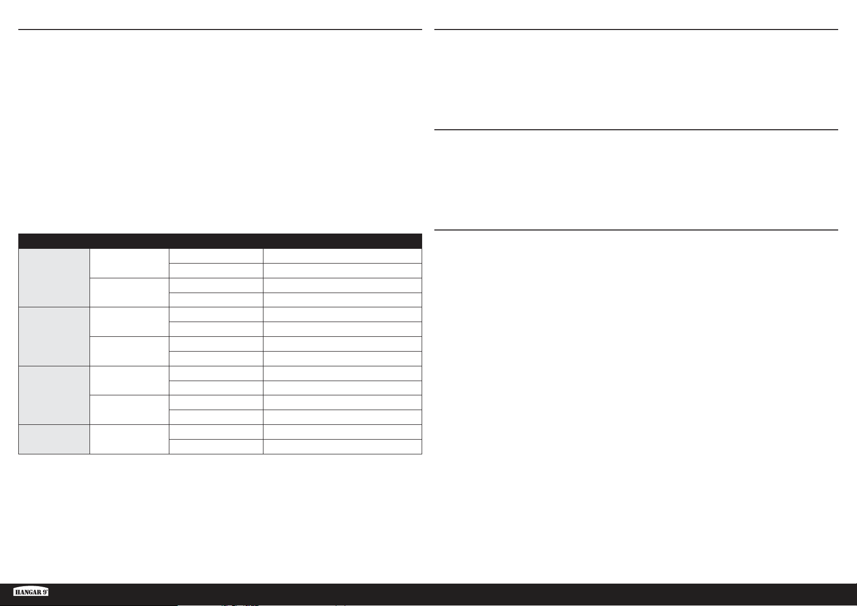
2. The recommended Center of Gravity (CG) location for your model is 6 inches (152.5mm) behind the leading edge
of the wing. Take this measurement against the fuselage where the wheel well extends forward of the leading
edge of the wing.
3. When balancing your model, make sure it is assembled and ready for fl ight. Support the plane inverted at the
marks made on the wing with your fi ngers or a commercially available balancing stand.
1
The overall CG range for this model is 5
at the measurement listed above, then adjusting to suit your particular flying style.
/2–7 inches (140–178mm). We recommend starting
17. Apply epoxy to the mounts using an epoxy brush.
18. Place the mounts in position in the cowling. Allow the epoxy to fully
cure before proceeding.
Create a fillet extending out 1/2 inch (13mm) from the mounts
to increase the
19. Install the muffl er on the engine. Trim the cowling as necessary to
clear the muffl er or any other parts of the engine that may protrude
outside the cowling. Mount the cowling back on the fuselage. Install
the spinner backplate, propeller and spinner on the engine.
bond between the mount and cowling.
Nose weight may be required when using lighter weight engines. Move the batteries
as far forward in the fuselage to help reduce the amount of weight required.
CAUTION: You must adjust your aircraft’s center of
gravity and balance your model properly before attempting fl ights.
6 inches
(152.5mm)
34EN
Page 35
CONTROL THROWS
1. Turn on the transmitter and receiver of your model. Check the movement of the rudder using the transmitter.
When the stick is moved to the right, the rudder should also move right. Reverse the direction of the servo at the
transmitter if necessary.
2. Check the movement of the elevator with the radio system. Moving the elevator stick toward the bottom of the
transmitter will make the airplane elevator move up.
3. Check the movement of the ailerons with the radio system. Moving the aileron stick to the right will make the
right aileron move up and the left aileron move down.
4. Use a ruler to adjust the throw of the elevator, ailerons and rudder.
These are general guidelines for general sport and aerobatic fl ying from our own fl ight tests. You can experiment with
higher or lower rates to match your preferred style of fl ying.
Travel Adjust and Sub-Trims are not listed and should be adjusted according to each individual model and preference.
Always install the control horns 90 degrees to the servo center line. Use sub-trim as a last resort to center the servos.
Always re-bind the radio system once all the control throws are set to keep the servos from moving to their endpoints
until the transmitter and receiver connect.
Surface Rate Direction Throw
High
Aileron
Low
High
Elevator
Low
High
Rudder
Low
Flaps
Up 25/32 inches (20mm)
Down 19/32 inches (15mm)
Up 19/32 inches (15mm)
Down 1/2 inches (13mm)
Up 1/2 inches (13mm)
Down 1/2 inches (13mm)
Up 13/32 inches (10mm)
Down 13/32 inches (10mm)
Left 131/32 inches (50mm)
31
Right 1
Left 13/16 inches (30mm)
Right 13/16 inches (30mm)
Take-Off 1–13/16 inches (25–30mm)
Landing 131/
/32 inches (50mm)
–23/8 inches (50–60mm)
32
PREFLIGHT CHECKLIST
• Charge the transmitter, receiver and motor batteries. Follow the instructions provided with the charger. Follow all
manufacturer’s instructions for your electronic components.
• Check the radio installation and make sure all control surfaces (aileron, elevator, rudder, and fl aps) move correctly
(i.e., the correct direction and with the recommended throws).
• Check all the hardware (control horns, servo horns, and clevises) to make sure they are secure and in good condition.
• Prior to each fl ying session (and especially with a new model), perform a range check of your radio system. See your
radio manual for the recommended range and instructions for your particular radio system.
DAILY FLIGHT CHECKS
• Check the battery voltage of the transmitter battery. Do not fl y below the manufacturer’s recommended voltage.
Doing so can cause your aircraft to crash.
• Check all hardware (linkages, screws, nuts, and bolts) prior to each day’s fl ight. Ensure that binding does not occur
and that all parts are properly secured.
• Ensure all surfaces are moving in the proper manner.
• Perform a ground range check before each day’s fl ying session.
• All servo leads and switch harness plugs should be secured in the receiver.
LIMITED WARRANTY
What this Warranty Covers
Horizon Hobby, LLC, (Horizon) warrants to the original purchaser that the product purchased (the “Product”) will be free from
defects in materials and workmanship at the date of purchase.
What is Not Covered
This warranty is not transferable and does not cover (i) cosmetic damage, (ii) damage due to acts of God, accident, misuse,
abuse, negligence, commercial use, or due to improper use, installation, operation or maintenance, (iii) modifi cation of or to
any part of the Product, (iv) attempted service by anyone other than a Horizon Hobby authorized service center, (v) Product
not purchased from an authorized Horizon dealer, (vi) Product not compliant with applicable technical regulations, or (vii) use
that violates any applicable laws, rules, or regulations.
OTHER THAN THE EXPRESS WARRANTY ABOVE, HORIZON MAKES NO OTHER WARRANTY OR REPRESENTATION,
AND HEREBY DISCLAIMS ANY AND ALL IMPLIED WARRANTIES, INCLUDING, WITHOUT LIMITATION, THE IMPLIED
WARRANTIES OF NON-INFRINGEMENT, MERCHANTABILITY AND FITNESS FOR A PARTICULAR PURPOSE. THE PURCHASER
ACKNOWLEDGES THAT THEY ALONE HAVE DETERMINED THAT THE PRODUCT WILL SUITABLY MEET THE REQUIREMENTS
OF THE PURCHASER’S INTENDED USE.
Purchaser’s Remedy
Horizon’s sole obligation and purchaser’s sole and exclusive remedy shall be that Horizon will, at its option, either (i) service,
or (ii) replace, any Product determined by Horizon to be defective. Horizon reserves the right to inspect any and all Product(s)
involved in a warranty claim. Service or replacement decisions are at the sole discretion of Horizon. Proof of purchase is
required for all warranty claims. SERVICE OR REPLACEMENT AS PROVIDED UNDER THIS WARRANTY IS THE PURCHASER’S
SOLE AND EXCLUSIVE REMEDY.
Ki-43 Oscar 60cc ARF
35 EN
Page 36
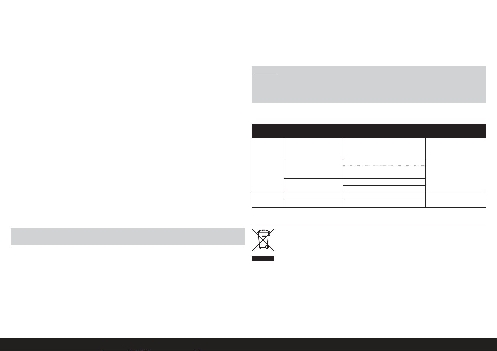
Limitation of Liability
HORIZON SHALL NOT BE LIABLE FOR SPECIAL, INDIRECT, INCIDENTAL OR CONSEQUENTIAL DAMAGES, LOSS OF PROFITS
OR PRODUCTION OR COMMERCIAL LOSS IN ANY WAY, REGARDLESS OF WHETHER SUCH CLAIM IS BASED IN CONTRACT,
WARRANTY, TORT, NEGLIGENCE, STRICT LIABILITY OR ANY OTHER THEORY OF LIABILITY, EVEN IF HORIZON HAS BEEN
ADVISED OF THE POSSIBILITY OF SUCH DAMAGES. Further, in no event shall the liability of Horizon exceed the individual price
of the Product on which liability is asserted. As Horizon has no control over use, setup, fi nal assembly, modifi cation or misuse,
no liability shall be assumed nor accepted for any resulting damage or injury. By the act of use, setup or assembly, the user
accepts all resulting liability. If you as the purchaser or user are not prepared to accept the liability associated with the use of
the Product, purchaser is advised to return the Product immediately in new and unused condition to the place of purchase.
Law
These terms are governed by Illinois law (without regard to confl ict of law principals). This warranty gives you specifi c legal
rights, and you may also have other rights which vary from state to state. Horizon reserves the right to change or modify this
warranty at any time without notice.
WARRANTY SERVICES
Questions, Assistance, and Services
Your local hobby store and/or place of purchase cannot provide warranty support or service. Once assembly, setup or
use of the Product has been started, you must contact your local distributor or Horizon directly. This will enable Horizon to
better answer your questions and service you in the event that you may need any assistance. For questions or assistance,
please visit our website at www.horizonhobby.com, submit a Product Support Inquiry, or call the toll free telephone number
referenced in the Warranty and Service Contact Information section to speak with a Product Support representative.
Inspection or Services
If this Product needs to be inspected or serviced and is compliant in the country you live and use the Product in, please use
the Horizon Online Service Request submission process found on our website or call Horizon to obtain a Return Merchandise
Authorization (RMA) number. Pack the Product securely using a shipping carton. Please note that original boxes may be
included, but are not designed to withstand the rigors of shipping without additional protection. Ship via a carrier that
provides tracking and insurance for lost or damaged parcels, as Horizon is not responsible for merchandise until it arrives
and is accepted at our facility. An Online Service Request is available at http://www.horizonhobby.com/content/servicecenter_render-service-center. If you do not have internet access, please contact Horizon Product Support to obtain a RMA
number along with instructions for submitting your product for service. When calling Horizon, you will be asked to provide
your complete name, street address, email address and phone number where you can be reached during business hours.
When sending product into Horizon, please include your RMA number, a list of the included items, and a brief summary of
the problem. A copy of your original sales receipt must be included for warranty consideration. Be sure your name, address,
and RMA number are clearly written on the outside of the shipping carton.
NOTICE: Do not ship LiPo batteries to Horizon. If you have any issue with a LiPo battery, please contact the
appropriate Horizon Product Support offi ce.
Warranty Requirements
For Warranty consideration, you must include your original sales receipt verifying the proof-of-purchase date. Provided
warranty conditions have been met, your Product will be serviced or replaced free of charge. Service or replacement
decisions are at the sole discretion of Horizon.
Non-Warranty Service
Should your service not be covered by warranty, service will be completed and payment will be required without notifi cation or
estimate of the expense unless the expense exceeds 50% of the retail purchase cost. By submitting the item for service you
are agreeing to payment of the service without notifi cation. Service estimates are available upon request. You must include this
request with your item submitted for service. Non-warranty service estimates will be billed a minimum of ½ hour of labor. In
addition you will be billed for return freight. Horizon accepts money orders and cashier’s checks, as well as Visa, MasterCard,
American Express, and Discover cards. By submitting any item to Horizon for service, you are agreeing to Horizon’s Terms and
Conditions found on our website http://www.horizonhobby.com/content/service-center_render-service-center.
ATTENTION: Horizon service is limited to Product compliant in the country of use and ownership. If received,
a non-compliant Product will not be serviced. Further, the sender will be responsible for arranging return
shipment of the un-serviced Product, through a carrier of the sender’s choice and at the sender’s expense.
Horizon will hold non-compliant Product for a period of 60 days from notifi cation, after which it will be
discarded.
10/15
WARRANTY AND SERVICE CONTACT INFORMATION
Country of
Purchase
United States
of America
European
Union
Horizon Hobby Contact Information Address
Horizon Service Center
(Repairs and Repair
Requests)
Horizon Product Support
(Product Technical
Assistance)
Sales
Horizon Technischer Service [email protected]
Sales: Horizon Hobby GmbH +49 (0) 4121 2655 100
servicecenter.horizonhobby.com/
RequestForm/
877-504-0233
[email protected]
800-338-4639
2904 Research Road
Champaign, IL 61822
Hanskampring 9
D 22885 Barsbüttel, Germany
INSTRUCTIONS FOR DISPOSAL OF WEEE BY USERS IN THE EUROPEAN UNION
This product must not be disposed of with other waste. Instead, it is the user’s responsibility to dispose of their
waste equipment by handing it over to a designated collections point for the recycling of waste electrical and
electronic equipment. The separate collection and recycling of your waste equipment at the time of disposal
will help to conserve natural resources and ensure that it is recycled in a manner that protects human health
and the environment. For more information about where you can drop off your waste equipment for recycling,
please contact your local city offi ce, your household waste disposal service or where you purchased the
product.
36EN
Page 37

ACADEMY OF MODEL AERONAUTICS NATIONAL MODEL AIRCRAFT SAFETY CODE
Effective January 1, 2018
A model aircraft is a non-human-carrying device capable of sustained fl ight within visual line of sight of the
pilot or spotter(s). It may not exceed limitations of this code and is intended exclusively for sport, recreation,
education and/or competition. All model fl ights must be conducted in accordance with this safety code and
related AMA guidelines, any additional rules specifi c to the fl ying site, as well as all applicable laws and
regulations.
As an AMA member I agree:
• I will not fl y a model aircraft in a careless or reckless manner.
• I will not interfere with and will yield the right of way to all human-carrying aircraft using AMA’s See and Avoid
Guidance and a spotter when appropriate.
• I will not operate any model aircraft while I am under the infl uence of alcohol or any drug that could adversely affect
my ability to safely control the model.
• I will avoid fl ying directly over unprotected people, moving vehicles, and occupied structures.
• I will fl y Free Flight (FF) and Control Line (CL) models in compliance with AMA’s safety programming.
• I will maintain visual contact of an RC model aircraft without enhancement other than corrective lenses prescribed to
me. When using an advanced fl ight system, such as an autopilot, or fl ying First-Person View (FPV), I will comply with
AMA’s Advanced Flight System programming.
• I will only fl y models weighing more than 55 pounds, including fuel, if certifi ed through AMA’s Large Model Airplane
Program.
• I will only fl y a turbine-powered model aircraft in compliance with AMA’s Gas Turbine Program.
• I will not fl y a powered model outdoors closer than 25 feet to any individual, except for myself or my helper(s)
located at the fl ightline, unless I am taking off and landing, or as otherwise provided in AMA’s Competition
Regulation.
• I will use an established safety line to separate all model aircraft operations from spectators and bystanders.
For a complete copy of AMA’s Safety Handbook please visit:
Ki-43 Oscar 60cc ARF
www.modelaircraft.org/fi les/100.pdf
37 EN
Page 38
HINWEIS
Alle Anweisungen, Garantien und andere Begleitdokumente können von Horizon Hobby, LLC nach eigenem Ermessen
geändert werden. Um aktuelle Produktinformationen zu erhalten, besuchen Sie horizonhobby.com oder www.
towerhobbies.com und klicken Sie auf die Registerkarte Support oder Ressourcen für dieses Produkt.
SPEZIELLE BEDEUTUNGEN
Die folgenden Begriffe werden in der gesamten Produktliteratur verwendet, um auf unterschiedlich hohe
Gefahrenrisiken beim Betrieb dieses Produkts hinzuweisen:
WARNUNG: Wenn diese Verfahren nicht korrekt befolgt werden, ergeben sich wahrscheinlich Sachschäden,
Kollateralschäden und schwere Verletzungen ODER mit hoher Wahrscheinlichkeit oberfl ächliche Verletzungen.
ACHTUNG: Wenn diese Verfahren nicht korrekt befolgt werden, ergeben sich wahrscheinlich Sachschäden UND die
Gefahr von schweren Verletzungen.
HINWEIS: Wenn diese Verfahren nicht korrekt befolgt werden, können sich möglicherweise Sachschäden UND
geringe oder keine Gefahr von Verletzungen ergeben.
WARNUNG: Lesen Sie die GESAMTE Bedienungsanleitung, um sich vor dem Betrieb mit den Produktfunktionen
vertraut zu machen. Wird das Produkt nicht korrekt betrieben, kann dies zu Schäden am Produkt oder persönlichem
Eigentum führen oder schwere Verletzungen verursachen.
Dies ist ein hochentwickeltes Hobby-Produkt. Es muss mit Vorsicht und gesundem Menschenverstand betrieben
werden und benötigt gewisse mechanische Grundfähigkeiten. Wird dieses Produkt nicht auf eine sichere und
verantwortungsvolle Weise betrieben, kann dies zu Verletzungen oder Schäden am Produkt oder anderen Sachwerten
führen. Dieses Produkt eignet sich nicht für die Verwendung durch Kinder ohne direkte Überwachung eines
Erwachsenen. Verwenden Sie das Produkt nicht mit inkompatiblen Komponenten oder verändern es in jedweder Art
ausserhalb der von Horizon Hobby, LLC vorgegebenen Anweisungen. Diese Bedienungsanleitung enthält Anweisungen
für Sicherheit, Betrieb und Wartung. Es ist unbedingt notwendig, vor Zusammenbau, Einrichtung oder Verwendung
alle Anweisungen und Warnhinweise im Handbuch zu lesen und zu befolgen, damit es bestimmungsgemäß betrieben
werden kann und Schäden oder schwere Verletzungen vermieden werden.
Nicht geeignet für Kinder unter 14 Jahren. Dies ist kein Spielzeug.
WARNUNGEN UND SICHERHEITS-VORKEHRUNGEN
Bitte lesen und befolgen Sie alle Anweisungen und Sicherheitsvorkehrungen vor dem Gebrauch. Falscher, nicht
sachgemäßer Gebrauch kann Feuer, ernsthafte Verletzungen und Sachbeschädigungen zur Folge haben.
Komponenten
Verwenden Sie mit dem Produkt nur kompatible Komponenten. Sollten Fragen zur Kompatibilität auftreten, lesen Sie
bitte die Produkt- oder Bedienungsanweisung oder kontaktieren den Service von Horizon Hobby.
Fliegen
Fliegen Sie um Sicherheit garantieren zu können, nur in weiten offenen Gegenden. Wir empfehlen hier den Betrieb auf
zugelassenen Modellfl ugplätzen. Bitte beachten Sie lokale Vorschriften und Gesetze, bevor Sie einen Platz zum Fliegen
wählen.
Propeller
Halten Sie lose Gegenstände, die sich im Propeller verfangen können, immer vom Propeller fern. Dazu gehören lose
Kleidung oder andere Gegenstände wie Stifte und Schraubendreher. Halten Sie Ihre Hände vom Propeller fern, da es zu
Verletzungen kommen kann.
Akkus
Folgen Sie immer den Herstelleranweisungen bei dem Gebrauch oder Entsorgung von Akkus. Falsche Behandlung von
LiPo Akkus kann zu Feuer mit Körperverletzungen und Sachbeschädigung führen.
Kleinteile
Dieser Baukasten beinhaltet Kleinteile und darf nicht unbeobachtet in der Nähe von Kindern gelassen werden, da die
Teile verschluckt werden könnten mit ernsthaften Verletzung zur Folge.
EMPFEHLUNGEN ZUM SICHEREN BETRIEB
• Überprüfen Sie zur Flugtauglichkeit ihr Modell vor jedem Flug.
• Beachten Sie andere Piloten deren Sendefrequenzen ihre Frequenz stören könnte.
• Begegnen Sie anderen Piloten in ihrem Fluggebiet immer höfl ich und respektvoll.
• Wählen Sie ein Fluggebiet, dass frei von Hindernissen und groß genug ist.
• Stellen Sie vor dem Start sicher, dass die Fläche frei von Freunden und Zuschauern ist.
• Beobachten Sie den Luftraum und andere Flugzeuge/Objekte die ihren Flugweg kreuzen und zu einem Konfl ikt
führen könnten.
• Planen Sie sorgfältig ihren Flugweg vor dem Start.
VOR DEM ZUSAMMENBAU
• Entnehmen Sie zur Überprüfung jedes Teil der Verpackung.
• Überprüfen Sie den Rumpf, Tragfl ächen, Seiten- und Höhenruder auf Beschädigung.
• Sollten Sie beschädigte oder fehlende Teile feststellen, kontaktieren Sie bitte den Verkäufer.
• Laden des Senders und Empfängers.
• Zentrieren der Trimmungen und Sticks auf dem Sender.
• Sollten Sie einen Computersender verwenden, resetten Sie einen Speicherplatz und benennen ihn nach dem Modell.
• Sender und Empfänger jetzt nach den Bindeanweisung des Herstellers zu binden.
HINWEIS: Das Funksystem nach dem Einstellen der Ruderausschläge erneut binden. Damit wird verhindert, dass sich
die Servos auf ihre Endpunkte bewegen, ehe Sender und Empfänger verbunden sind. Außerdem wird garantiert, dass
die Servo-Umkehreinstellungen im Funksystem gespeichert werden.
FÜR SEHBEHINDERTE
Auf der Seite www.horizonhobby.com fi nden Sie unter der Registerkarte für dieses bestimmte Modell eine Ausgabe
dieses Handbuchs. Sie können dieses Handbuch herunterladen und mit einem PDF-Viewer in alle Texte oder Bilder
hineinzoomen, die beim Zusammenbau auf der Grundlage des gedruckten Handbuchs nicht eindeutig zu erkennen
sind.
38DE
Page 39
INHALTSVERZEICHNIS
Hinweis .................................................................................................................................................................38
Spezielle Bedeutungen ..........................................................................................................................................38
Warnungen und Sicherheits-vorkehrungen ............................................................................................................38
Empfehlungen zum sicheren Betrieb ......................................................................................................................38
Vor dem Zusammenbau .........................................................................................................................................38
Für Sehbehinderte .................................................................................................................................................38
Ersatzteile ..............................................................................................................................................................39
Erforderliche Klebemittel ........................................................................................................................................39
Zur Fertigstellung erforderlich, Alle Antriebsoptionen ..............................................................................................40
Zur Fertigstellung erforderlich, Montage des Benzinmotors ....................................................................................40
Zur Fertigstellung erforderlich, Montage des Elektromotors ....................................................................................40
Sonderzubehör ......................................................................................................................................................40
Werkzeuge erforderlich ..........................................................................................................................................40
Hinweise zur Bespannung ......................................................................................................................................41
Vorsichtsmaßnahmen beim Zusammenbau ............................................................................................................41
Transport und Lagerung .........................................................................................................................................41
Überprüfen der Blindmuttern ..................................................................................................................................41
Buggewicht ...........................................................................................................................................................41
Montage des einziehbaren Fahrwerks ....................................................................................................................41
Montage des Querruders .......................................................................................................................................45
Aufhängen der Querruder.......................................................................................................................................47
Montage des Querruder-Servos .............................................................................................................................48
Aufhängen der Klappen ..........................................................................................................................................50
Montage des Klappen-Servos ................................................................................................................................51
Montage des Abwurftanks .....................................................................................................................................53
Montage des Stabilisators ......................................................................................................................................54
Montage des Höhenruders .....................................................................................................................................56
Montage des Seitenruders .....................................................................................................................................57
Montage des Seitenruder-Gestänges .....................................................................................................................57
Montage des Spornrads .........................................................................................................................................58
Montage von Pilot und Kanzel ................................................................................................................................60
Montage des Elektromotors ...................................................................................................................................61
Montage des Benzinmotors ....................................................................................................................................63
Montage des Kraftstofftanks ..................................................................................................................................65
Montage des Luftsystems des einziehbaren Fahrwerks ..........................................................................................66
Montage des Empfängers ......................................................................................................................................68
Montage von Motorhaube und Spinner ...................................................................................................................68
Schwerpunkt .........................................................................................................................................................70
Ruderausschlag .....................................................................................................................................................71
Vorfl ugkontrolle .....................................................................................................................................................71
Täglicher Flug Check ............................................................................................................................................71
Garantie Und Service Informationen .......................................................................................................................71
Garantie und Service Kontaktinformationen............................................................................................................72
Anweisungen zur Entsorgung von Elektro- und Elektronik-Altgeräten für Benutzer in der Europäischen Union ........72
ERSATZTEILE
Teile-Nr. Beschreibung
HAN472001 Nur KI-43 Oscar 60cc Flugwerk
HAN472002 Rumpf mit Haube: Ki-43 60cc
HAN472003 LH Flügel mit Querruder und Klappe: Ki-43 60cc
HAN472004 RH Flügel mit Querruder und Klappe: Ki-43 60cc
HAN472005 Stabilisator mit Höhenruder: KI-43 60cc
HAN472006 Seitenleitwerk: Ki-43 60cc
HAN472007 Motorhaube und Motorattrappe: Ki-43 60cc
HAN472008 Obere Abdeckung: Ki-43 60cc
HAN472009 Kabinenhaube: Ki-43 60cc
HAN472010 Lackierter Pilot: Ki-43 60cc
HAN472011 Kleinteile Set: Ki-43 60cc
HAN472012 Haupträder 12,7cm (5Zoll): Ki-43 60cc
HAN472013 Spornrad m. Zbh. : Ki-43 60cc
HAN472014 Gestänge / Anlenkungen Set: Ki-43 60cc
HAN472015 Spinner 95.25 mm: Ki-43 60cc
HAN472016 Tragfl ächenverbinder: Ki-43 60cc
HAN472017 Kraftstofftank: Ki-43 60cc
HAN472018 E-Motorhalter Set: Ki-43 60cc
HAN472019 Fahrwerkklappen-Satz: Ki-43 60cc
HAN472020 Maßstabsgetreue Details: Ki-43 60cc
HAN472025 Einziehbares Fahrwerkset: Ki-43 60cc
HAN472026 Einziehbare Fahrwerke und Streben: Ki-43 60cc
HAN472027 Hardware des Belüftungssystems: Ki-43 60cc
HAN472028 Streben des einziehbaren Fahrwerks: Ki-43 60cc
ERFORDERLICHE KLEBEMITTEL
Beschreibung
15 Minuten Epoxy
30 Minuten Epoxy
Sekundenkleber mittel
Sekundenkleber dünnfl üssig
Gewindesicherung, hohe und niedrige Festigkeit
Ki-43 Oscar 60cc ARF
39 DE
Page 40
ZUR FERTIGSTELLUNG ERFORDERLICH, ALLE ANTRIEBSOPTIONEN
Erforderliche
Anz.
1 SPMAR12310T PowerSafe-Telemetrieempfänger AR12310T mit 12 Kanälen
7 SPMSA6320 A6320 H-T/H-S Brushless HV-Servo
1 SPMSA6110 A6110 M-T/M-S Standard HV-Servo (Luftventil einziehbares Fahrwerk)
2 SPMA3000 Servokabelverlängerung 75 mm (3 inch)
4 SPMA3002 Servokabelverlängerung 230 mm (9 inch)
Teile-Nr. Beschreibung
ZUR FERTIGSTELLUNG ERFORDERLICH, MONTAGE DES BENZINMOTORS
Erforderliche
Anz.
2 SPMSA6110 A6110 HV Standard Servo
1 DLEG0061 DLE-61cc Gasmotor mit elektrischer Zündung
1 DUB800 Tygon Kraftstoffl eitung, 91 cm (3 Fuß) groß
1 HAN116 Hangar 9 Tanknippel mit T Stück u. Überlauf Fitting
1 SPM9530 Spektrum Kabel mit 3-Drahtschalter
3 SPMB4000LPRX LiPo-Empfängerakku (7,4 V / 4000 mAh)
Teile-Nr. Beschreibung
ZUR FERTIGSTELLUNG ERFORDERLICH, MONTAGE DES ELEKTROMOTORS
Erforderliche
Anz.
1 GPMG4805 Rimfi re 65cc Elektromotor
1 CSE010013100 Talon HV120 Geschwindigkeitsregler 010-0131-00
Teile-Nr. Beschreibung
SONDERZUBEHÖR
Teile-Nr. Beschreibung
EVOA100 Optischer Zünd-Notausschalter
SAIEG90R3 FG-90R3 90cc Dreizylinder-Sternmotor
SPMAS3000 AS3000 AS3X Stabilisierungsmodul
WERKZEUGE ERFORDERLICH
Beschreibung
Ring- oder Maulschlüssel: 10mm, 11mm (7/16Zoll), 13 mm (1/2 Zoll)
Schraubzwinge
Folienbügeleisen
Trennscheibe
Bohrer
Bohrer- und Gewindebohrersatz, metrisch
Pinsel
Faserstift
Schraubendreher
Flachfeile
Flussmittelpaste
Heißluftpistole
Klemme
Sechskantsatz, metrisch
Hobbymesser mit # 11 Klinge
Hobbyschere
Rechteck
Klettband
Nähmaschinenöl
Kreppband
Schleifpapier mittel
Mischbecher und Rührstäbchen
Stift
Phillips Schraubendreher: #1,#2
Handbohrer
Zange
Säge
elektrischer Handbohrer
Lineal
Schleiftrommel
Schere
Seitenschneider
Silberlot
Stufenreibahle
Zahnstocher
Schweißbrenner oder Lötkolben
Schraubzwinge
Abisolierzange
40DE
Page 41
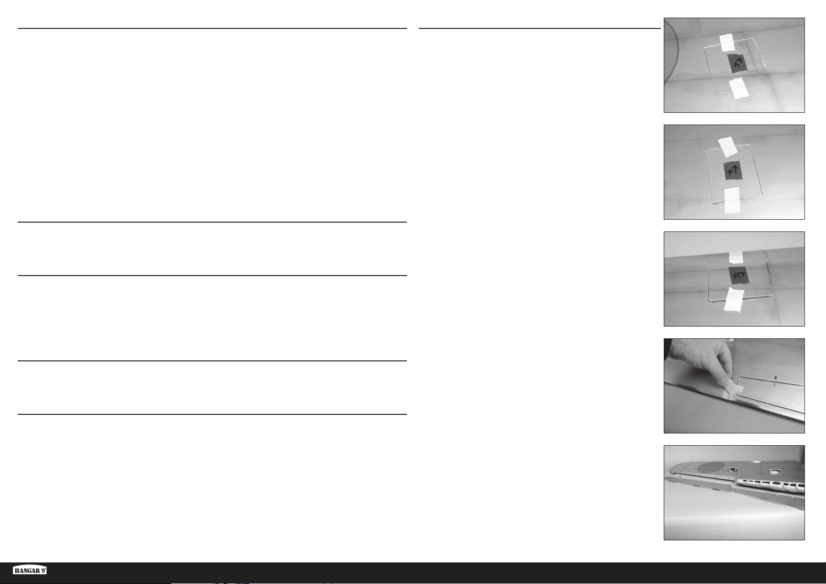
HINWEISE ZUR BESPANNUNG
• Bei der bei diesem Modell verwendeten Abdeckung sind Farben und Markierungen direkt auf die Abdeckung
gedruckt.
• Die Abdeckung ist selbstklebend, und ein Erwärmen wird nicht empfohlen, da die Wärme die Abdeckung
beschädigen könnte.
• Verwenden Sie nur milde Reiniger für die bedruckte Folie. Als aggressiver Reiniger der noch zu empfehlen ist,
empfehlen wir denaturierten Alkohol. Prüfen Sie vorher unbedingt an unauffälliger Stelle die Verträglichkeit.
Wiederholte / verlängerte Anwendung entfernt die Farbe.
• Verwenden Sie Klebeband nur mit äußerster Vorsicht. Bis auf Kreppband entfernt alle Klebebänder die Farbe. Dieses
gilt insbesondere für die Kanten.
• Vermeiden Sie den Kontakt mit Kraftstoff, insbesondere Alkohol-basierte Kraftstoffe mit Nitromethan.
• Entfernen Sie Abgasrückstände schnellstmöglich um ein Verfärben oder Beschädigen der Bespannung zu vermeiden.
Zwei Stellen Ihres Modells sind bei normalem Gebrauch Verschleiß ausgesetzt. Bei der ersten Stelle handelt es sich um
den Bereich, in dem die Motorhaube auf der Rumpfabdeckung sitzt und in dem die Tragfl äche in den Rumpf führt. Indem
Sie die Tragfl äche dort, wo sie in den Rumpf führt, sowie an der Abdeckung unter der Motorhaube mit einem Stück
transparentem Klebeband versehen, können Sie den Verschleiß der Abdeckung reduzieren. Außerdem vermindern Sie den
Verschleiß der Abdeckung unter der Motorhaube, wenn Sie die Innenseite der Motorhaube mit Sandpapier glattschmirgeln.
VORSICHTSMASSNAHMEN BEIM ZUSAMMENBAU
Die Arbeitsfl äche vor dem Zusammenbau vorbereiten. Die Oberfl äche sollte weich und frei von scharfen Objekten sein.
Wir empfehlen, die Teile des Flugwerks auf einem weichen Handtuch oder einer Matte zu lagern, um Kratzer oder
Beulen an der Oberfl äche des Flugzeugs zu vermeiden.
TRANSPORT UND LAGERUNG
Beim Transport und der Lagerung des Modells müssen mindestens 2.1m in der Länge und 50 cm in der Höhe
vorhanden sein, um die Größe des Rumpfs aufnehmen zu können. Wir empfehlen außerdem die Verwendung von
Tragfl ächen- und Stabilisatortaschen, um die Oberfl ächen bei Transport und Lagerung zu schützen. Selbst wenn sie
in Taschen gelagert sind, können die Steuerhörner und Gestänge Schäden an anderen Oberfl ächen verursachen. Die
Tragfl ächen und den Stabilisator immer so transportieren und lagern, dass die Gestänge keine anderen Teile berühren
und somit Schäden verhindert werden.
ÜBERPRÜFEN DER BLINDMUTTERN
Beim Bau des Flugzeugs müssen Maschinenschrauben in Blindmuttern eingeschraubt werden. Um sicherzustellen,
dass die Blindmuttern frei von Verunreinigungen sind, empfehlen wir, die Schrauben vorzudrehen. Lassen sich die
Schrauben nur schwer einschrauben, mit einem passenden Gewindeschneider mit Griff die Gewinde gängig machen.
MONTAGE DES EINZIEHBAREN FAHRWERKS
1. Mit einem Klebeband geringer Klebekraft das Querruder, die
Klappen und die Abdeckung des einziehbaren Fahrwerks markieren,
damit sie in der korrekten Ausrichtung wieder an der Tragfl äche
angebracht werden können. Den auf die Vorderkante weisenden
Pfeil als Referenz verwenden.
2. Das Klebeband von der Tragfl äche entfernen, mit dem Querruder und
die Klappe an der Tragfl äche gesichert werden.
BUGGEWICHT
Dieses Modell wird wahrscheinlich für das korrekte Gleichgewicht ein zusätzliches Buggewicht benötigen. Alle
Antriebsoptionen wurden getestet. Die Verwendung eines schwereren Antriebs oder Motors trägt dazu bei, das
erforderliche Zusatzgewicht zu reduzieren. Achten Sie darauf, dass Sie beim Fliegen mit diesen größeren und
leistungsfähigeren Modellen eine angemessene Gassteuerung anwenden. Unser Testfl ugzeug verfügte über den
empfohlenen Evolution
Die Verwendung anderer Motoren als den empfohlen kann ein zusätzliches Gewicht für das korrekte Gleichgewicht
erforderlich machen. Dies kann von Flugzeug zu Flugzeug unterschiedlich sein. Das Gewicht so weit vorne im Rumpf
wie möglich unterbringen, um die für das Gleichgewicht benötigte Menge zu reduzieren. Das Gewicht muss gesichert
werden, damit es sich im Flug nicht löst, das Modell unsicher wird und es zu einer Beschädigung des Flugzeugs
kommt.
Ki-43 Oscar 60cc ARF
®
62cc Motor und Schalldämpfer sowie Empfänger- und Zündakkus unter dem Kraftstofftank.
3. Querruder und Klappen vom Flügel trennen. An einem sicheren Ort
ablegen.
41 DE
Page 42
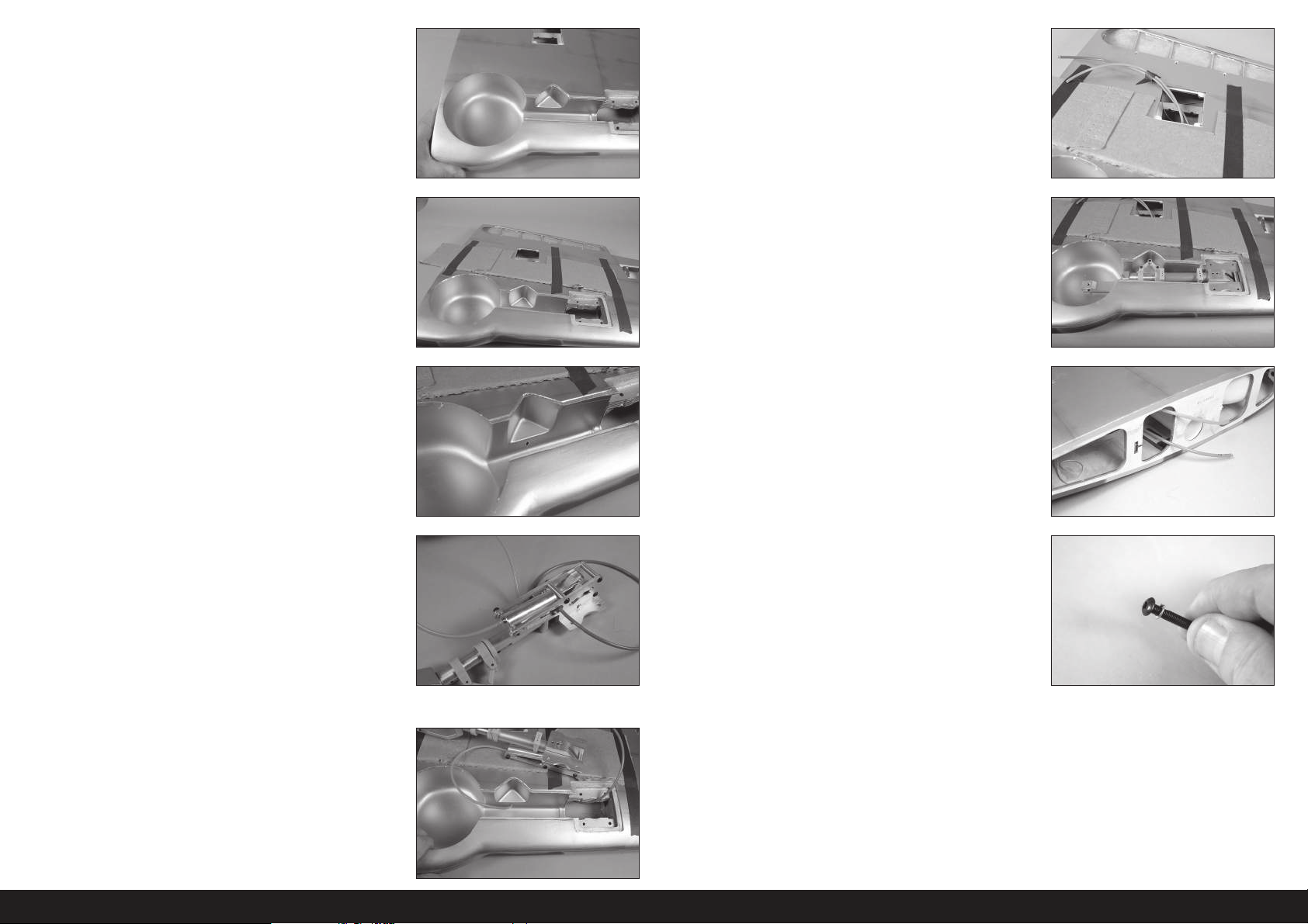
4. Mit einem Hobbymesser und einer Klinge der Nr.11 die Abdeckung
von den Öffnungen für das einziehbare Fahrwerk in der Tragfl äche
entfernen. Die Abdeckung in der Öffnung kürzen.
9. Beide Luftleitungen können an der Öffnung des Klappen-Servos
herausgezogen werden. Mit einem Klebeband geringer Klebekraft
die Leitungen zusammen sichern, damit sie nicht wieder in die
Tragfl äche fallen.
5. Mit einem Klebeband geringer Klebekraft ein Stück Karton über der
Tragfl äche sichern. Dadurch wird eine Stelle erschaffen, an der das
einziehbare Fahrwerk beim Verlegen der Luftleitungen ruht, und um
Schäden an der Unterseite der Tragfl äche zu vermeiden.
6. Mit einem Feilkloben und einem 3mm (1/8Zoll) Bohrer ein Loch im
einziehbaren Fahrwerk für die Luftleitungen schaffen.
7. Ein 482mmm (19Zoll) großes Stück der orangefarbenen und blauen
Luftleitung schneiden. Jede Luftleitung am einziehbaren Fahrwerk
anbringen. Durch die Verwendung verschiedener Farben wird der
korrekte Anschluss der einziehbaren Fahrwerke bei der Montage des
Modells erleichtert.
Mit einer Heißluftpistole auf schwacher Hitze die Luftleitungen
leicht weich machen, damit sie durch die Fittings passen.
10. Das einziehbare Fahrwerks im Flügel einpassen. Nach Bedarf
trimmen, um für den entsprechenden Abstand zu sorgen.
11. Die Luftleitungen können nun an der Tragfl ächenwurzel
herausgezogen werden.
12. Eine Sicherungsscheibe auf die M4 x 25 Rundkopfschraube
platzieren. Zum jetzigen Zeitpunkt vier Schrauben vorbereiten.
Sicherstellen, dass die Farben der Luftleitung auf dem linken
und rechten einziehbaren Fahrwerk gleich ausgerichtet sind,
damit beide auf die gleiche Art und Weise funktionieren.
8. Die Luftleitungen durch die Tragfl äche verlegen.
42DE
Page 43
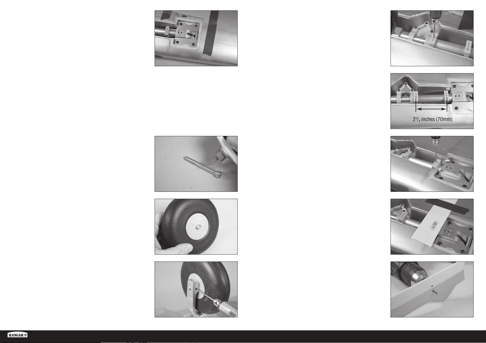
13. Mit den M4 x 25 Rundkopfschrauben das einziehbare Fahrwerk
in der Tragfl äche sichern. Vor der Montage der Schrauben einen
Tropfen Gewindesicherung auf jede Schraube geben. Die Schrauben
mit einem 2,5mm Sechskant festziehen.
Der Karton kann nach dem Sichern des einziehbaren
Fahrwerks von der Tragfläche entfernt werden.
Es kann erforderlich sein, Abstandshalter unter dem Rahmen des
einziehbaren Fahrwerks zu verwenden, um sicherzustellen, dass
beim Festziehen keine Torsionsspannung anliegt. Torsionsspannung
kann zu einem unzuverlässigen Betrieb der Einzieheinheit führen.
17. Die Halterung der Fahrwerkklappen so nah wie möglich am Rad
positionieren. Der fl ache Bereich wird sich mit der Unterseite der
Tragfl äche ausrichten. Mit einer M3x5 Feststellschraube und einem
1,5mm Sechskant die Position der Fahrwerkklappen-Halterung
sichern.
Die Schrauben nicht zu fest anziehen und
keinen Gewindekleber verwenden, da dies das
Verbundmaterial der Halterungen beschädigt.
18. Die obere Halterung 70mm (23/4 Zoll) von der unteren Halterung
entfernt positionieren.
14. Einen Tropfen leichtes Maschinenöl auf die M6x55
Zylinderkopfschrauben auftragen, die als Radachse fungiert.
15. Die M6x55 Zylinderkopfschraube durch das Rad schieben.
Sicherstellen, dass sich das Rad frei auf der Schraube drehen kann.
16. Die Schraube in das einziehbare Fahrwerk schrauben. Die Schraube
so weit festziehen, dass sich das Rad frei drehen kann, es aber
nicht zu übermäßigen Bewegungen des Rads auf der Schraube
kommt. Danach mit einer M3x5 Feststellschraube und einem
2mm Sechskant die Feststellschraube festziehen. Einen Tropfen
Gewindesicherung auf die M6x55 Zylinderkopfschraube auf die
M3x5 Feststellschraube auftragen, um ein Lösen unter Vibrationen
zu verhindern.
19. Mit einer M3x5 Feststellschraube und einem 1,5mm Sechskant
die Position der Fahrwerkklappen-Halterung sichern.
Die Schrauben nicht zu fest anziehen und
keinen Gewindekleber verwenden, da dies das
Verbundmaterial der Halterungen beschädigt.
20. Ein Stück Papier an die Tragfl äche kleben, das über die obere
Halterung geht. Mit einem Bleistift über das Papier streichen, um die
Position der Befestigungslöcher zum Vorschein zu bringen.
21. Mit einem 3mm (1/8Zoll) Bohrer die Befestigungslöcher für das
untere Fahrwerk in die Fahrwerkklappe bohren.
Ki-43 Oscar 60cc ARF
43 DE
Page 44
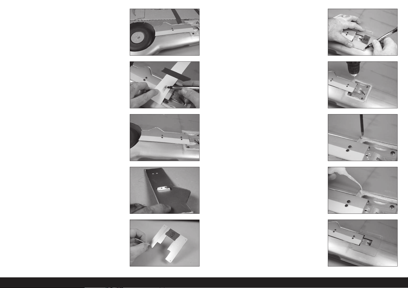
22. Die Fahrwerkklappe mit zwei M3x12 Rundkopfschrauben und
einem 2mm Sechskant an der Halterung anbringen.
Die Position der Klappe überprüfen, um sicherzustellen,
dass diese mittig in der Öffnung liegt und mit der
Öffnung nahe dem Rad ausgerichtet ist.
Die Schrauben nicht zu fest anziehen und
keinen Gewindekleber verwenden, da dies das
Verbundmaterial der Halterungen beschädigt.
27. Die Abdeckung in Position bringen. Mit einem Filzstift die Positionen
der Befestigungsschrauben markieren
23. Mit einem Filzstift die Position der Befestigungsschrauben der
oberen Fahrwerkklappe auf der Fahrwerkklappe markieren.
24. Die Abdeckung entfernen und mit einem 3mm (1/8Zoll) Bohrer
die zwei Löcher für die Befestigungsschrauben der oberen
Fahrwerkklappe bohren. Die Fahrwerkklappe kann nun mit vier
M3x12 Rundkopfschrauben und einem 2mm Sechskant an der
Halterung angebracht werden.
25. Liegt die Fahrwerkklappe mit der Unterseite der Tragfl äche nicht
bündig, so müssen die Halterungen angepasst werden. Der
Befestigungsbereich für die untere Halterung kann außerdem mit
Sandpapier mittlerer Körnung geschliffen werden, um Anpassungen
an der Ausrichtung der Fahrwerkklappen vorzunehmen.
28. Mit einem 1,5mm (1/16Zoll) Bohrer die Montagelöcher für die
Abdeckungen des einziehbaren Fahrwerks bohren.
29. Eine M2x10 Blechschraube mit einem Kreuzschlitzschraubendreher
Nr.1 in jedes Loch schrauben. Die Schrauben vor dem Fortfahren
entfernen.
30. Eine kleine Menge dünnen CA-Klebstoff zum Härten der im
vorherigen Schritt erzeugten Gewinde auftragen. Der CA-Klebstoff
muss vollständig gehärtet sein, ehe die Abdeckung des einziehbaren
Fahrwerks montiert werden kann.
26. Mit einem Hobbymesser oder einem anderen spitzen Werkzeug die
Abdeckung der Schraublöcher durchstechen, die die Abdeckung an
der Tragfl äche fi xieren. Außerdem die Abdeckung zum Freilegen des
Einfahrmechanismus entfernen.
31. Die Abdeckung des einziehbaren Fahrwerks mit vier M2x10
Blechschrauben an der Tragfl äche sichern. Mit einem
Kreuzschlitzschraubendreher Nr.1 die Schrauben festziehen.
44DE
Page 45
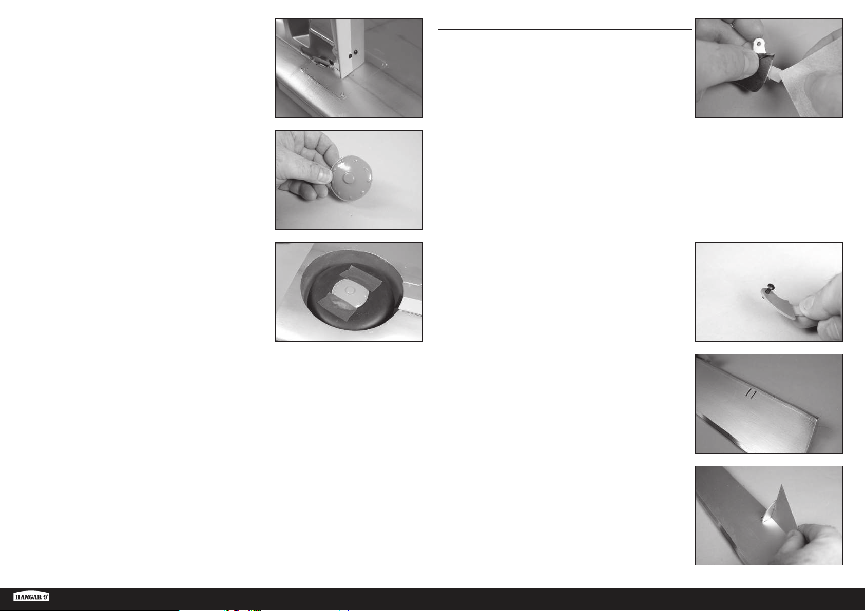
32. Prüfen, dass das einziehbare Fahrwerk vollständig ausgefahren
werden kann, ohne dass dabei die Fahrwerkklappe die Abdeckung
berührt. Die Fahrwerkklappe entsprechend trimmen, wenn diese die
Abdeckung berührt.
Während des Betriebs des Fahrwerks kommt es zu einer
Bewegung. Daher sicherstellen, dass eine Lücke zwischen der
Fahrwerkklappe und der Tragfläche besteht, damit beide sich
während des Betriebs des Fahrwerks nicht gegenseitig berühren.
33. Mit einer Hobbyschere und Sandpapier mittlerer Körnung die
Nabenkappe für die Montage vorbereiten.
Die Nabenkappe kann nach Wunsch lackiert werden.
Sicherstellen, dass die Oberfläche komplett geschliffen und
vorbereitet ist. Das Auftragen von Lack auf die unvorbereitete
Nabenkappe führt zu abblätternder Farbe. Mit dem Lack
immer einen Test auf einem Stück Abfallmaterial durchführen,
um die Kompatibilität mit dem Kunststoff zu prüfen.
MONTAGE DES QUERRUDERS
1. Mit Sandpapier mittlerer Körnung das Steuerhorn dort leicht
schleifen, wo es in die Steuerfl äche eingesetzt wird. Den mit
Sandpapier bearbeiteten Bereich mit einem Papiertuch und
Isopropylalkohol von Schmutz und Öl reinigen. Dadurch wird eine
Oberfl ächentextur geschaffen, die zur Verbindung mit dem Epoxid
notwendig ist.
Den lackierten Bereich mit Klebeband abdecken,
um eine Beschädigung des freiliegenden Bereichs
des Steuerhorns zu vermeiden. Das Klebeband
entfernen, sobald das Steuerhorn geschliffen ist.
34. Mit Kontaktkleber die Nabenkappe am Rad befestigen. Mit einem
Klebeband mit geringer Klebekraft die Nabenkappe in Position
halten, bis der Klebstoff vollständig ausgehärtet ist.
Diesen Abschnitt zur Montage der verbleibenden
Einziehbaugruppe wiederholen.
2. Die M3x10 Rundkopfschraube in das Loch im Steuerhorn
einführen. Lack mit einem Hobbymesser und einer Klinge Nr.11
entfernen, damit die Schraube problemlos in das Loch passt. Alle
Steuerhörner überprüfen.
Die Öffnung sollte so groß sein, dass die Schraube
hindurch und dennoch passgenau in die Öffnung
passt und sich nicht übermäßig bewegt.
3. Mit dem Finger entlang der Unterseite des Querruders fahren,
um die korrekte Stelle für das Steuerhorn zu fi nden. Mit einem
Hobbymesser und einer Klinge Nr.11 die Abdeckung entfernen, um
die Schlitze für das Steuerhorn freizulegen.
4. Das Steuerhorn probeweise in den Schlitz einsetzen. Beim Einsetzen
des Steuerhorns in den Schlitz keine Kraft aufwenden. Einen Winkel
verwenden, um sicherzustellen, dass das Steuerhorn rechtwinklig
zur Steuerfl äche sitzt. Beim Einsetzen des Steuerhorns in den Schlitz
keine Kraft aufwenden.
Ki-43 Oscar 60cc ARF
45 DE
Page 46
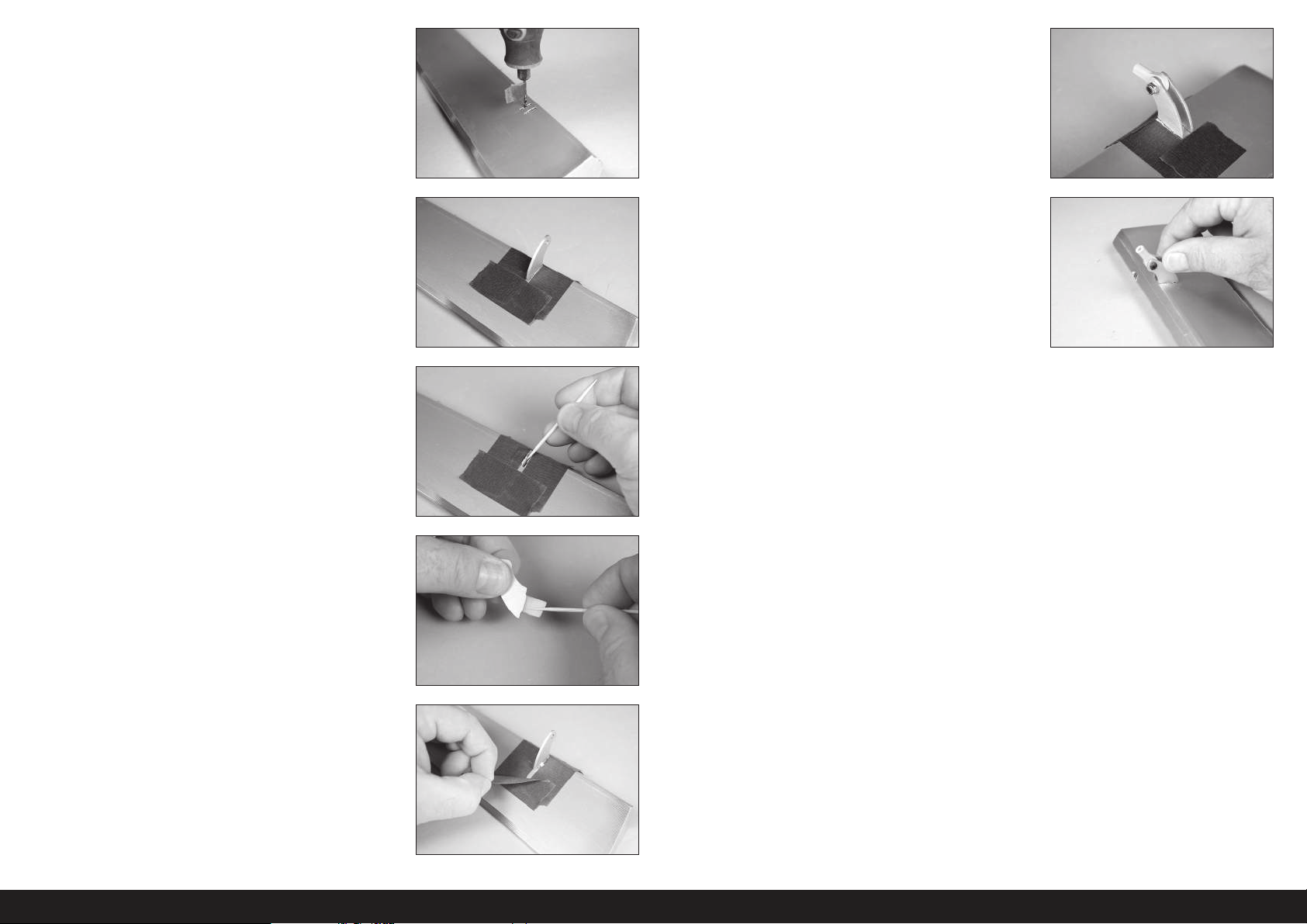
Wenn das Steuerhorn zu fest oder nicht rechtwinklig sitzt, ein
Rotationswerkzeug mit einem 2,5mm (3/32Zoll) Bohrer verwenden,
um das Loch vorsichtig zu vergrößern und umzuformen. Ein Stück
Klebeband mit geringer Klebekraft um den Bohrer wickeln, um
die Tiefe des Bohrers so einzustellen, dass er nicht versehentlich
in die gegenüberliegende Seite der Steuerfläche eindringt.
9. Das verbleibende Steuerhorn probeweise einsetzen. Beim Kleben
des Steuerhorns den Kugelkopf zwischen die Hörner platzieren
und die M3x10 Rundkopfschraube durch die Steuerhörner und
Stangenköpfe einführen. Dadurch werden die Hörner korrekt
ausgerichtet und die spätere Montage des Gestänges wird
erleichtert.
5. Klebeband um den Schlitz im Querruder für das Querruder-
Steuerhorn platzieren.
6. Die Steuerhörner von den Steuerfl ächen entfernen. Epoxid auf den
Schlitz im Querruder auftragen. Sicherstellen, dass das Epoxid für
eine gute Bindung zwischen den Oberfl ächen und dem Steuerhorn in
den Schlitz gelangt.
7. Epoxid auf den Bereich des Steuerhorns auftragen, der in den Schlitz
passt. Ausreichend Epoxid verwenden, damit sich das Steuerhorn
vollständig mit den Steuerfl ächen verbindet.
10. Nachdem das Epoxid vollständig gehärtet ist, am Steuerhorn ziehen,
um sicherzustellen, dass es sicher am Querruder klebt. Falls nicht,
das Steuerhorn entfernen und sämtlichen Kleber mit Sandpapier
abschleifen. Diesen Abschnitt zum Festkleben des Steuerhorns im
Querruder wiederholen.
8. Ehe das Epoxid vollständig ausgehärtet ist, das Klebeband um
das Steuerhorn entfernen. Dadurch kann das Epoxid um das
Steuerhorn fl ießen und für eine kleine Leiste zwischen Steuerhorn
und Oberfl äche für ein abgeschlossenes Aussehen und eine sichere
Verbindung sorgen. Das Epoxid muss vor dem Fortfahren vollständig
ausgehärtet sein.
46DE
Page 47
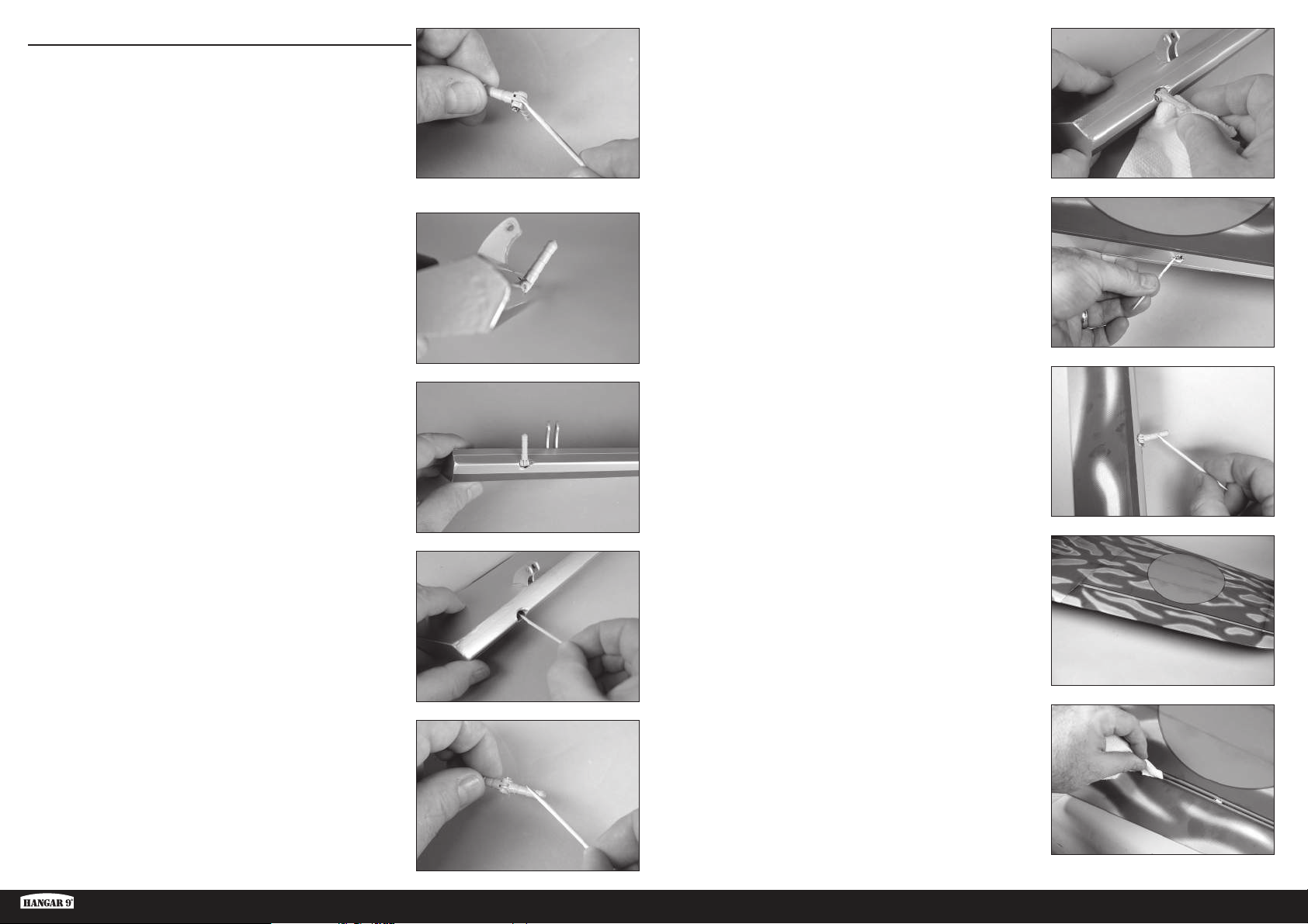
AUFHÄNGEN DER QUERRUDER
Das Epoxid erst nach Aufforderung mischen.
Die kurzen Aufhängungen für die Querruder verwenden. Die
längeren Aufhängungen werden aufgrund der verwendeten
Aufhängmethode für die Klappen verwendet.
1. Eine kleine Menge Öl auf den Flexpunkt der Aufhängungen
auftragen, um ein Eindringen des Epoxids in die Aufhängung zu
verhindern.
2. Die Aufhängung so einführen, dass die Mitte des Gelenkpunkts mit
der Vorderkante der Schräge auf der Steuerfl äche ausgerichtet ist.
Prüfen, dass sich die Aufhängung ungehindert bewegen kann.
3. Die Aufhängung so positionieren, dass sie bei vollständiger
Auslenkung senkrecht zur Linie steht.
6. Die Aufhängungen in die Steuerfl äche einführen. Bestätigen, dass
die Aufhängung korrekt positioniert ist. Mit einem Papiertuch und
Isopropylalkohol überschüssiges Epoxid entfernen. Das Epoxid muss
vor dem Fortfahren vollständig ausgehärtet sein.
7. 15ml (1/2 oz) 30-minütiges Epoxid mischen. Mit einem Zahnstocher
Epoxid auf die Innenseiten der Löcher für die Aufhängungen
auftragen.
8. Epoxid auf die Außenseiten der Aufhängung mit einem Zahnstocher
auftragen
4. 15ml (1/2 oz) 30-minütiges Epoxid mischen. Die Aufhängungen
entfernen und dann mit einem Zahnstocher Epoxid auf die
Innenseiten der Löcher für die Aufhängung auftragen.
5. Epoxid auf die Außenseiten der Aufhängung mit einem Zahnstocher
auftragen
Ki-43 Oscar 60cc ARF
9. Das Querruder an der Tragfl äche einpassen. Prüfen, ob sich
das Querruder frei bewegen kann und alle Aufhängen korrekt
ausgerichtet sind.
10. Mit einem Papiertuch und Isopropylalkohol überschüssiges Epoxid
entfernen. Mit einem Klebeband mit geringer Klebekraft das
Querruder in Position halten, bis das Epoxid vollständig ausgehärtet
ist.
47 DE
Page 48
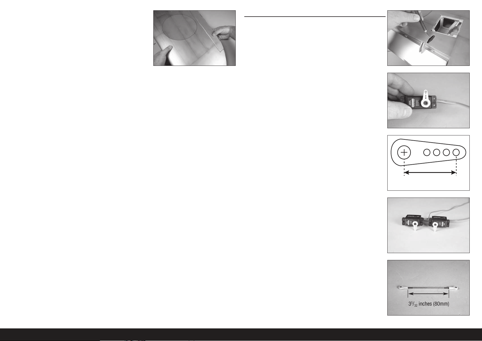
11. Nachdem das Epoxid vollständig gehärtet ist, an der Tragfl äche
ziehen, um sicherzustellen, dass die Aufhängungen sicher verklebt
sind. Falls nicht, das Querruder entfernen und sämtlichen Kleber
mit Sandpapier abschleifen. Diesen Abschnitt zum Festkleben der
Aufhängungen wiederholen.
MONTAGE DES QUERRUDER-SERVOS
1. Mit einem Hobbymesser und einer Klinge Nr.11 die Abdeckung für
den Austritt der Schubstange des Querruders entfernen.
2. Den Querruder-Servo zentrieren. Das Servohorn senkrecht zur
Mittellinie des Servos am Servo anbringen.
3. Beim Anbringen des Gestänges am Querruder-Servoarm die Öffnung
im Arm verwenden, die 16mm (5/8Zoll) von der Mitte des Arms
entfernt liegt.
5/8 inch
(16mm)
4. Zum jetzigen Zeitpunkt den linken und rechten Servo des Querruders
vorbereiten.
5. Das Gestänge für das Querruder mit zwei Kugelköpfen und
der Gewindestange von 100mm (3
Die Gelenkkopfenden mit 12Umdrehungen auf das Gestänge
schrauben. Die Länge anpassen, so dass der Abstand zwischen den
Kugelköpfen 80mm (3
48DE
5
/32 Zoll) beträgt.
15
/16 Zoll) zusammenbauen.
Page 49
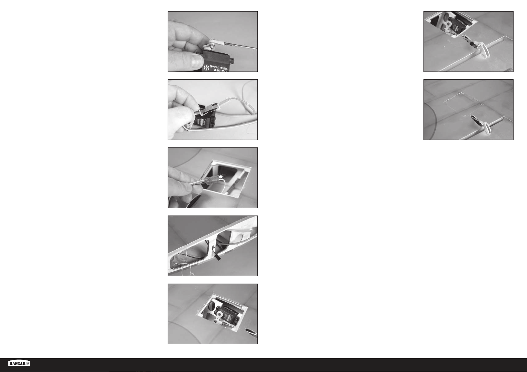
6. Den Servo-Gelenkkopf mit einer M3x10 Rundkopfschraube, einer
M3 Unterlegscheibe und einer M3 Kontermutter am Servoarm
sichern. Mit einem 2,5mm Sechskant und einem 5,5mm
Steckschlüssel die Hardware festziehen.
11. Den Servo-Gelenkkopf mit einer M3x10 Rundkopfschraube, einer
M3 Unterlegscheibe und einer M3 Kontermutter am Steuerhorn
befestigen. Mit einem 2,5mm Sechskant und einem 5,5mm
Steckschlüssel die Hardware festziehen.
Den Servo mit dem Funksystem verbinden, um den Servo des
Querruders in der zentrierten Position zu halten. Die Kugel
vom Steuerhorn trennen und das Gestänge ausrichten, damit
sich das Querruder in neutraler Position befindet. Nach dem
Anpassen des Gestänges die Hardware wieder montieren.
7. Eine 150mm (6Zoll) Servoverlängerung am Servo mit einem
käufl ich erhältlichen Halter (SPMA3054) sichern.
Die Länge der Verlängerung kann abhängig von der
Wahl des Servos variieren. Die aufgeführte Verlängerung
funktioniert mit den empfohlenen Servos.
8. Die im Inneren der Tragfl äche befi ndliche Schnur an das Ende der
Servoleitung knoten oder mit Klebeband kleben.
9. Mit der Schnur die Servoleitung durch die Tragfl äche und an der
Tragfl ächenwurzel herausziehen.
Wir haben ein kleines Stück der Schnur an der Servoleitung
des Querruders belassen, damit sie schnell von der später zu
montierenden Servoleitung der Klappen unterschieden werden kann.
12. Die für die Abdeckung des einziehbaren Fahrwerks aufgeführten
Schritte zur Montage der Querruderabdeckung verwenden.
10. Den Querruder-Servo in der Tragfl äche montieren, wobei
der Ausgang auf die Vorderkante weist. Sicherstellen, die
Befestigungslöcher des Servos vorzubereiten, indem eine
Befestigungsschraube in jedes Loch gedreht und dann wieder
entfernt wird. Die Löcher für die Befestigungsschrauben vor der
Montage der Servos mit dünnem CA-Klebstoff härten.
Ki-43 Oscar 60cc ARF
49 DE
Page 50
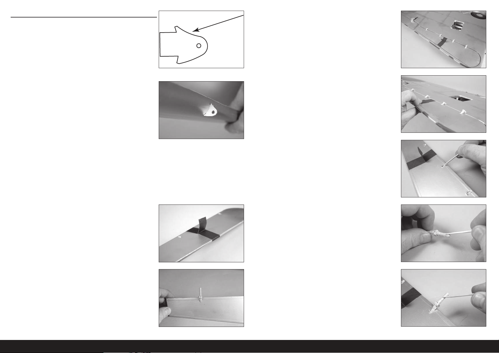
AUFHÄNGEN DER KLAPPEN
Die Klappen müssen an der Tragfläche positioniert
werden, bevor die Aushärtung des Epoxids beginnt. Vor
der Zubereitung von Epoxid alle Schritte durchlesen. Nur
jeweils eine Klappe verkleben, um genügend Arbeitszeit
zur korrekten Montage der Aufhängungen zu haben.
1. Die Steuerhörner der Klappe lokalisieren. Nach der Montage zeigt
die konkave Stelle des Steuerhorns (wie in der Abbildung dargestellt)
zur Oberseite der Klappen.
2. Mit dem Finger entlang der Vorderkante der Klappe fahren, um die
korrekte Stelle für die Steuerhörner der Klappe zu fi nden. Mit einem
Hobbymesser und einer Klinge Nr.11 die Abdeckung entfernen, um
die Schlitze für das Steuerhorn freizulegen. Mit dem 15-minütigen
Epoxid die Steuerhörner der Klappe in Position kleben. Mit einem
Papiertuch und Isopropylalkohol sämtliche Epoxidrückstände
entfernen.
Zur Montage der Steuerhörner der Klappe die für die
Steuerhörner des Querruders dargelegten Schritte
verwenden. Unbedingt überprüfen, dass die Steuerhörner
der Klappe nach dem vollständigen Aushärten des
Klebstoffs sicher in den Klappen geklebt sind.
5. Den Sitz der Klappe zur Tragfl äche messen. Sie wird in der Öffnung
mittig passen. Der Scharnierstift wird direkt über der Lücke
zwischen der Vorderkante der Klappen und der Hinterkante der
Tragfl ächenöffnung positioniert. Das Funktionieren der Klappe
prüfen, um sicherzustellen, dass die Aufhängungen korrekt
ausgerichtet sind und sich die Klappe ungehindert bewegen kann.
6. Die Klappe ist außerdem mit der Unterseite der Tragfl äche
ausgerichtet, wenn die Aufhängungen korrekt positioniert sind.
15- oder 30-minütigen Epoxid verwenden, um bei der Montage
der Aufhängungen für genügend Arbeitszeit zu sorgen.
7. Die Klappe von der Tragfl äche nehmen und die Aufhängungen
entfernen. Epoxid in jedes Loch der Klappe geben.
Beim Verkleben der Aufhängungen nicht zu viel Epoxid
verwenden. Eine für das sichere Verkleben der Aufhängungen
an den Oberflächen ausreichende Menge Epoxid verwenden.
3. Ein Stück Klebebands mit geringer Klebekraft um die Klappe
winkeln, um eine Lasche zu erschaffen, damit die Klappe beim
Einpassen der Aufhängungen angehoben und gesenkt werden kann.
Die langen Aufhängungen zum Montieren der
Klappen an der Tragfläche verwenden.
4. Probieren, ob die Aufhängungen in die Klappe passen. Zum jetzigen
Zeitpunkt noch keine Klebstoffe verwenden. Die Aufhängung in
Position schieben. Entsprechen der Abbildung positionieren und
darauf achten, dass sich die Aufhängung ungehindert bewegen
kann.
8. Epoxid an der Stelle auf jede Aufhängung auftragen, die in die
Klappe eingeführt wird. Die Aufhängungen in die Klappe einführen.
9. Epoxid an der Stelle auf jede Aufhängung auftragen, die in die
Tragfl äche eingeführt wird.
50DE
Page 51
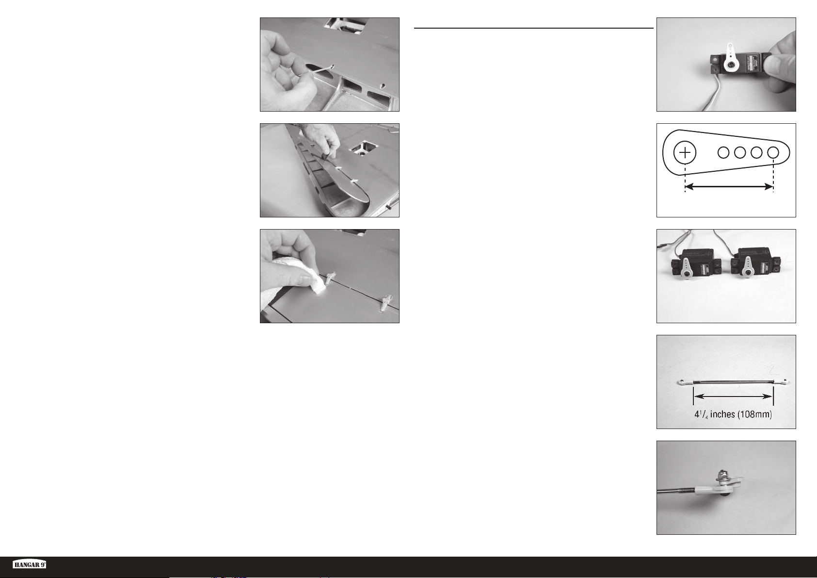
10. Epoxid in jedes Loch der Tragfl äche geben.
MONTAGE DES KLAPPEN-SERVOS
1. Den Klappen-Servo zentrieren. Das Servohorn senkrecht zur
Mittellinie des Servos am Servo anbringen.
Wir empfehlen, den Ausschlag auf 0° bei Funksystemen mit einem
Dreistellungsschalter einzustellen, um Schäden am Servo zu
verhindern, falls das Gestänge nicht die korrekte Länge aufweist.
11. Die Klappe in die Tragfl äche einpassen. Prüfen, ob sich die Klappe
ungehindert bewegen kann und alle Aufhängen korrekt ausgerichtet
sind. Mit einem Klebeband mit geringer Klebekraft die Klappe in
Position halten, bis das Epoxid vollständig ausgehärtet ist.
12. Mit einem Papiertuch und Isopropylalkohol überschüssiges Epoxid
entfernen, ehe es vollständig aushärtet. Darauf achten, dass kein
Epoxid in das bewegliche Teil der Aufhängung oder zwischen Klappe
und Tragfl äche eindringt. Warten, bis das Epoxid auf beiden Seiten
der Klappenaufhängungen vollständig ausgehärtet ist.
Unbedingt überprüfen, dass die Aufhängungen der Klappe nach
dem vollständigen Aushärten des Klebstoffs sicher geklebt sind.
Diesen Abschnitt zur Montage der verbleibenden
Aufhängung wiederholen.
2. Beim Anbringen des Gestänges am Querruder-Servoarm die Öffnung
im Arm verwenden, die 16mm (5/8Zoll) von der Mitte des Arms
entfernt liegt.
3. Zum jetzigen Zeitpunkt den linken und rechten Servo der Klappe
vorbereiten.
4. Das Gestänge für die Klappe mit zwei Kugelköpfen und der
Gewindestange von 120mm (4
Die Gelenkkopfenden mit 12Umdrehungen auf das Gestänge
schrauben. Die Länge anpassen, so dass der Abstand zwischen den
Kugelköpfen 108mm (4
23
/32 Zoll) zusammenbauen.
1
/4 Zoll) beträgt.
5/8 inch
(16mm)
Ki-43 Oscar 60cc ARF
5. Den Servoarm vom Servo entfernen. Den Servo-Gelenkkopf mit einer
M3x10 Rundkopfschraube, einer M3 Unterlegscheibe und einer M3
Kontermutter am Servoarm sichern. Mit einem 2,5mm Sechskant
und einem 5,5mm Steckschlüssel die Hardware festziehen.
51 DE
Page 52
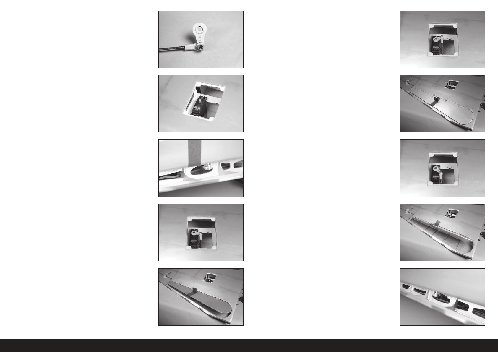
6. Der Kugelkopf wird an der Unterseite des Servoarms entsprechend
der Abbildung angebracht.
7. Den Klappen-Servo in der Tragfl äche montieren, wobei der Ausgang
auf die Vorderkante weist. Sicherstellen, die Befestigungslöcher des
Servos vorzubereiten, indem eine Befestigungsschraube in jedes
Loch gedreht und dann wieder entfernt wird. Die Löcher für die
Befestigungsschrauben vor der Montage der Servos mit dünnem
CA-Klebstoff härten.
Die Klappen-Servos können in der Tragfläche positioniert
werden, um die Verwendung eines Kabelbaums zum
Anschließen der Servos an den Empfänger zu ermöglichen.
11. Den Servo mit dem Funksystem in die ausgefahrene Klappenposition
bringen. Den Ruderausschlag im Funksystem anpassen, um die
Klappe auf die Unterseite der Tragfl äche auszurichten.
8. Den Servo-Gelenkkopf mit einer M3x10 Rundkopfschraube, einer
M3 Unterlegscheibe und einer M3 Kontermutter am Steuerhorn
befestigen. Mit einem 2,5mm Sechskant und einem 5,5mm
Steckschlüssel die Hardware festziehen.
9. Den Servoarm am Servo anbringen.
10. Die Länge des Gestänges anpassen, um die Klappen in der mittleren
Klappenposition von 25–30
Daran denken, den Ausschlag auf 0% in den Positionen
„Ausgefahren“ und „Eingefahren“ einzurichten, um Schäden
am Servo, an den Klappen oder am Gestänge zu verhindern.
mm zu positionieren
12. Den Servo mit dem Funksystem in die vollständig eingefahrene
Klappenposition von 50–60
Funksystem anpassen, um die aufgeführten Messwerte zu erzielen.
13. Das Gestänge kann abhängig von der Servoauswahl an der
Tragfl ächenstruktur reiben. Mit einem Hobbymesser mit einer
Klinge Nr.11 oder einem Rotationswerkzeug mit Schleifwalze die
Tragfl ächenstruktur nach Bedarf schleifen, damit das Gestänge frei
liegt.
mm bringen. Die Ausschläge mit dem
52DE
Page 53
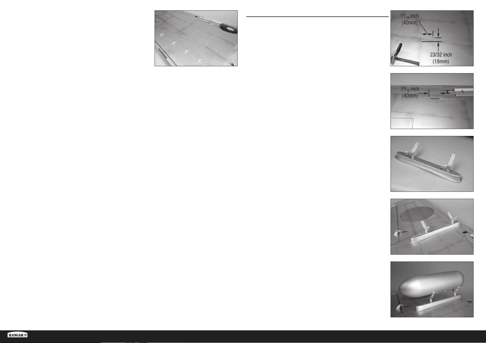
14. Die für die Abdeckung des einziehbaren Fahrwerks aufgeführten
Schritte zur Montage der Klappenabdeckung verwenden.
Diesen Abschnitt zur Montage des verbleibenden
Klappen-Servos wiederholen.
MONTAGE DES ABWURFTANKS
1. Mit dem Finger entlang der Unterseite der Tragfl äche fahren, um
die Position der Blindmuttern für die Halterung des Abwurftanks
zu fi nden. Mit einem Hobbymesser und einer Klinge Nr.11 die
Abdeckung zum Freilegen der Blindmuttern entfernen.
Zuerst per Hand eine Schraube in die Blindmuttern
drehen, um sicherzustellen, dass die Gewinde frei von
Verunreinigungen sind. Verkanten, zu starkes Anziehen oder
Beschädigen der Blindmuttern innerhalb der Tragfläche
werden umfangreiche Arbeiten zur Korrektur erfordern.
2. Die Befestigungen des Abwurftanks in die Blindmuttern im Mast
schrauben. Die Befestigungen nicht zu fest anziehen und den Mast
nicht beschädigen.
Ki-43 Oscar 60cc ARF
3. Den Mast mit zwei M4x15 Zylinderkopfschrauben und zwei M4
Sicherungsscheiben an der Tragfl äche anbringen. Mit einem 3mm
Sechskant die Schrauben festziehen.
Vor ihrer Montage einen Tropfen Kanzelkleber auf jede Schraube
auftragen. Dadurch können sich die Schrauben durch Vibrationen
nicht lösen, können jedoch einfach entfernt werden.
4. Den Abwurftank mit vier M3x12 Rundkopfschrauben an den
Halterungen befestigen. Mit einem 2mm Sechskant die Schrauben
festziehen.
Vor ihrer Montage einen Tropfen Kanzelkleber auf jede Schraube
auftragen. Dadurch können sich die Schrauben durch Vibrationen
nicht lösen, können jedoch einfach entfernt werden.
Diesen Abschnitt zur Montage des verbleibenden
Abwurftanks wiederholen.
53 DE
Page 54
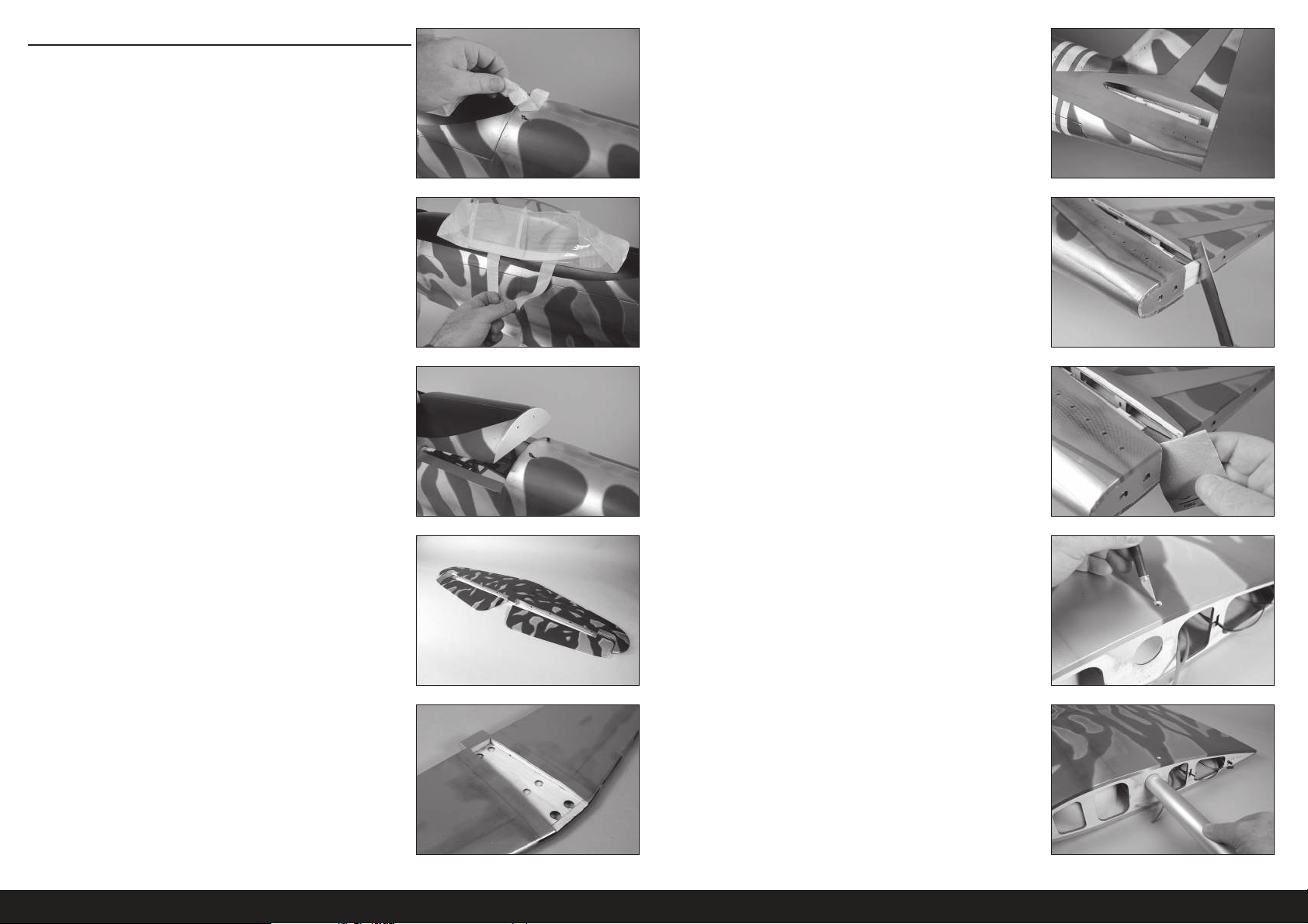
MONTAGE DES STABILISATORS
1. Das Klebeband und das Verpackungsmaterial vom Rumpf entfernen.
5. Mit dem Finger entlang der Rumpfseiten fahren, um die Öffnung für
den Stabilisator zu fi nden. Mit einem Hobbymesser und einer Klinge
Nr.11 die Abdeckung vom Rumpf entfernen.
6. Mit einer scharfen Säge den Abschnitt des Leitwerksmasts vom
Stabilisatorschlitz entfernen.
Der Leitwerkmast wird werkseitig angebracht, um
Beschädigungen zu vermeiden und die strukturelle Integrität
des Rumpfes während des Transports zu gewährleisten und
muss für die Montage des Stabilisators entfernt werden.
2. Den Verriegelungsschalter der Abdeckung zur Vorderseite des
Rumpfs bewegen. Die Kanzelabdeckung von hinten vom Rumpf
abheben und vom Rumpf entfernen. An einem sicheren Ort ablegen.
3. Die Höhenruder vom Stabilisator trennen. 8. Mit dem Finger entlang der Oberseite der Tragfl äche fahren, um
4. Mit dem Finger entlang der Unterseite des Stabilisators fahren, um
die Mitte zu fi nden. Mit einem Hobbymesser und einer Klinge Nr.11
die Abdeckung vom Mittelteil entfernen.
7. Mit Schleifpapier mittlerer Körnung den Rumpf mit dem
Stabilisatorschlitz glatt schleifen.
die Blindmutter für den Haltebolzen der Tragfl äche zu fi nden. Mit
einem Hobbymesser mit einer Klinge Nr.11 die Abdeckung von der
Tragfl äche entfernen, um die Blindmutter für den Haltebolzen der
Tragfl äche freizulegen.
Zur weiteren Sicherung kann Kleber auf die Blindmutter auf
der Innenseite der Tragfläche aufgetragen werden. Epoxid mit
Mikroballons funktioniert für diese Aufgabe ganz gut. Sicherstellen,
dass kein Klebemittel in die Gewinde der Blindmutter gelangt.
9. Das Steckungsrohr in die Steckungsrohrbuchse schieben.
Das Steckungsrohr kann sich schwer in die Buchse einsetzen
lassen. Das Polieren des Steckungsrohrs mit Sandpapier
feiner Körnung oder Stahlwolle erleichtert die Montage des
Steckungsrohrs. Beim Einsetzen des Steckungsrohrs in die
Buchse keine Kraft aufwenden, da dies Schäden in an der
Struktur innerhalb der Tragfläche verursachen kann.
54DE
Page 55
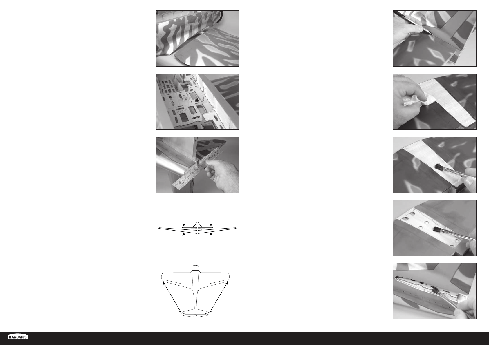
10. Die Tragfl äche in Position schieben. Die Klappen- und die
Querruderleitungen sowie die Luftleitungen des einziehbaren
Fahrwerks durch den Rumpf führen.
15. Mit einem Filzstift den Umriss des Rumpfes auf die Oberseite des
Stabilisators übertragen.
11. Die Tragfl äche mit der 1/4-20 x 1 Nylon-Flügelschraube am Rumpf
anbringen.
Die Schritte zum Sichern der verbleibenden
Tragfläche am Rumpf wiederholen.
12. Den Stabilisator in Position bringen. Eine gerade Kante zum
Ausrichten der Hinterseite des Stabilisators und des Seitenleitwerk
verwenden.
13. 2–3Meter (8–10Fuß) zurücktreten und überprüfen, ob der
Stabilisator mit der Tragfl äche ausgerichtet ist. Den Stabilisatorsattel
am Rumpf leicht schleifen, um etwaige Fehlausrichtungen zu
korrigieren.
A=A
16. Mit einem Lineal und einem Hobbymesser mit einer Klinge Nr.11
die Abdeckung 3mm (1/8 Zoll) innerhalb der gezogenen Linie auf
der Oberseite des Stabilisators schneiden, um die Abdeckung im der
Mitte des Stabilisators zu entfernen. Vorsicht walten lassen, um nicht
in das darunterliegende Holz zu schneiden, was zur Schwächung
des Stabilisators führen würde.
17. 25ml (3/4oz) 30-minütiges Epoxid mischen. Mit einer Epoxidbürste
das Epoxid auf das freigelegte Holz auf der Oberseite des
Stabilisators auftragen.
18. Mit einer Epoxidbürste das Epoxid ebenfalls auf das freigelegte Holz
auf der Unterseite des Stabilisators auftragen.
14. Von der Spitze jeder Tragfl äche bis zur Spitze jedes Stabilisators
messen. Den Stabilisator so anpassen, dass die Maße auf beiden
Seiten gleich sind.
Ki-43 Oscar 60cc ARF
AA
19. Mit einer Epoxidbürste das Epoxid auf die Montagefl äche für den
Stabilisator auftragen. Den Stabilisator wieder auf dem Rumpf
positionieren und die Ausrichtung überprüfen. Mit einem Papiertuch
und etwas Isopropylalkohol überschüssiges Epoxid von Rumpf und
Stabilisator entfernen, bevor das Epoxid vollständig aushärtet. Das
AA
A=A
Epoxid muss vor dem Fortfahren vollständig ausgehärtet sein.
Die Position des Stabilisators während des Aushärtens wiederholt
überprüfen, um sicherzugehen, dass er sich nicht verschoben hat.
55 DE
Page 56
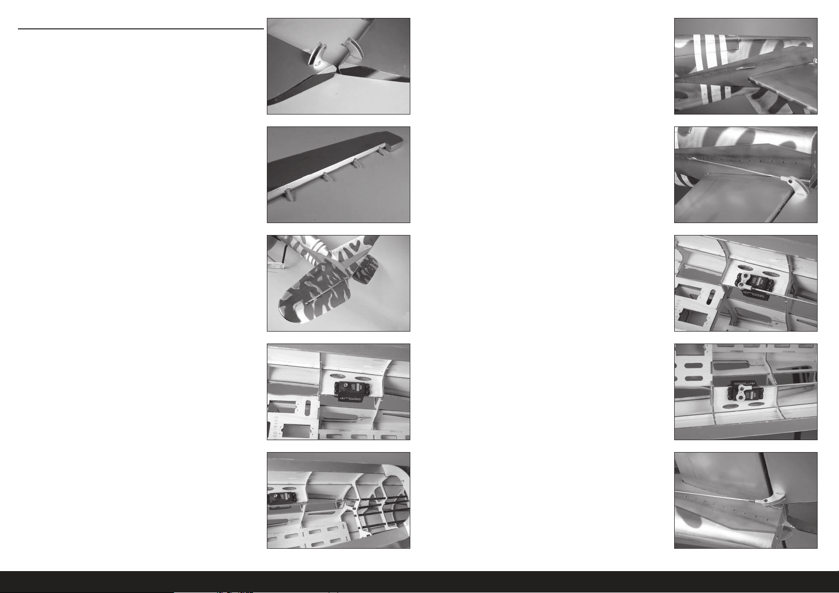
MONTAGE DES HÖHENRUDERS
1. Die Höhenruder-Steuerhörner montieren. Deren Montage entspricht
der Montage der Steuerhörner des Querruders.
Unbedingt überprüfen, dass die Steuerhörner
vor dem Fortfahren sicher verklebt sind.
6. Mit einem Hobbymesser mit einer Klinge Nr.11 die Abdeckung
trimmen, damit das Gestänge aus dem Rumpf treten kann.
2. Die Aufhängungen im Höhenruder mit 30-minütigem Epoxid kleben.
Die Montage der Höhenruder-Aufhängung ähnelt der Montage der
Querruder-Aufhängungen. Die kurzen Aufhängungen zum Aufhängen
der Höhenruder verwenden
3. Die Aufhängungen am Stabilisator mit 30-minütigem Epoxid kleben.
Unbedingt überprüfen, dass die Aufhängungen des
Höhenruders nach dem vollständigen Aushärten
des Klebstoffs sicher geklebt sind.
4. Die Löcher im Rumpf für den Höhenruder-Servo vorbereiten, indem
eine Schraube in jedes Loch geschraubt wird. Die Schrauben
entfernen und 2 bis 3 Tropfen dünnen CA-Klebstoff in jedes Loch
geben, um das umgebende Holz zu härten. Nach dem Aushärten
des CA-Klebstoffs den Höhenruder-Servo montieren, wobei die
Servoausgabewelle zur Vorderseite des Rumpfs weist.
7. Ein Gelenkkopfende mit 12Umdrehungen auf das Gestänge
schrauben. Den Servo-Gelenkkopf mit einer M3x10
Rundkopfschraube, einer M3 Unterlegscheibe und einer M3
Kontermutter am Steuerhorn befestigen. Mit einem 2,5mm
Sechskant und einem 5,5mm Steckschlüssel die Hardware
festziehen.
8. Den Höhenruder-Servo mit dem Funksystem zentrieren. Das
Servohorn senkrecht zum Gestänge am Servo anbringen. Ein
Gelenkkopfende mit 12Umdrehungen auf das Gestänge schrauben.
Den Servo-Gelenkkopf mit einer M3x10 Rundkopfschraube, einer
M3 Unterlegscheibe und einer M3 Kontermutter am Steuerhorn
befestigen. Mit einem 2,5mm Sechskant und einem 5,5mm
Steckschlüssel die Hardware festziehen.
9. Die vorherigen Schritte zur Montage des verbleibenden Höhenruder-
Servos und Gestänges wiederholen.
5. Ein Gestänge von 930mm (36
5
/8 Zoll) in das Gestängerohr schieben.
56DE
Page 57
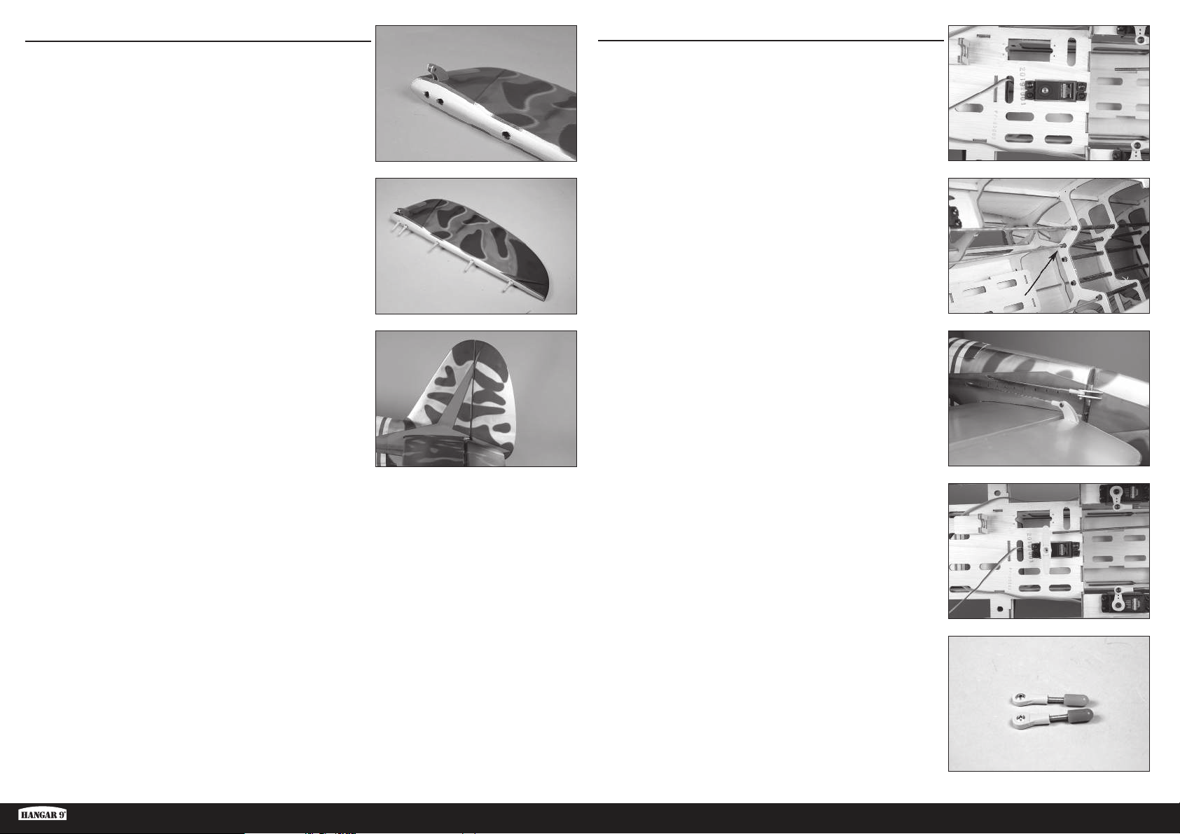
MONTAGE DES SEITENRUDERS
MONTAGE DES SEITENRUDER-GESTÄNGES
1. Die Seitenruder-Steuerhörner montieren. Deren Montage entspricht
der Montage der Steuerhörner des Querruders. Sicherstellen, die
Seitenruder-Steuerhörner auf der korrekten Seite des Seitenruders
zu montieren.
Unbedingt überprüfen, dass die Steuerhörner des Seitenruders nach
dem vollständigen Aushärten des Klebstoffs sicher geklebt sind.
2. Die Aufhängungen im Seitenruder mit 30-minütigem Epoxid kleben.
Die Montage der Seitenruder-Aufhängung ähnelt der Montage der
Querruder-Aufhängungen.
3. Die Aufhängungen am Seitenleitwerk mit 30-minütigem Epoxid
kleben.
Unbedingt überprüfen, dass die Aufhängungen des
Seitenruders nach dem vollständigen Aushärten
des Klebstoffs sicher geklebt sind.
1. Die Löcher im Rumpf für den Seitenruder-Servo vorbereiten, indem
eine Schraube in jedes Loch geschraubt wird. Die Schrauben
entfernen und 2 bis 3 Tropfen dünnen CA-Klebstoff in jedes Loch
geben, um das umgebende Holz zu härten. Nach dem Aushärten
des CA-Klebstoffs den Seitenruder-Servo montieren, wobei die
Servowelle zur Vorderseite des Rumpfs weist.
1
2. Ein Gestänge von 1020mm (40
Seitenruders schieben.
3. Ein Gelenkkopfende mit 12Umdrehungen auf das Gestänge
schrauben. Den Servo-Gelenkkopf mit einer M3x10
Rundkopfschraube, einer M3 Unterlegscheibe und einer M3
Kontermutter am Steuerhorn befestigen. Mit einem 2,5mm
Sechskant und einem 5,5mm Steckschlüssel die Hardware
festziehen.
/8 Zoll) in das Gestängerohr des
Ki-43 Oscar 60cc ARF
4. Den Seitenruder-Servo mit dem Funksystem zentrieren. Den
Servoarm auf den Servo platzieren, so dass er senkrecht zur
Mittellinie des Servos steht. Es kann notwendig sein, den Arm um
180° zu drehen, um eine bessere Ausrichtung des Arms auf dem
Servo zu erreichen. Den Arm so markieren, dass er zurück in seine
Position auf dem Servo gebracht werden kann.
5. Die Gelenkkopfenden mit 12Umdrehungen auf eine
Kabelverschraubung schrauben. Zum jetzigen Zeitpunkt zwei
Kabelverschraubungen vorbereiten.
57 DE
Page 58
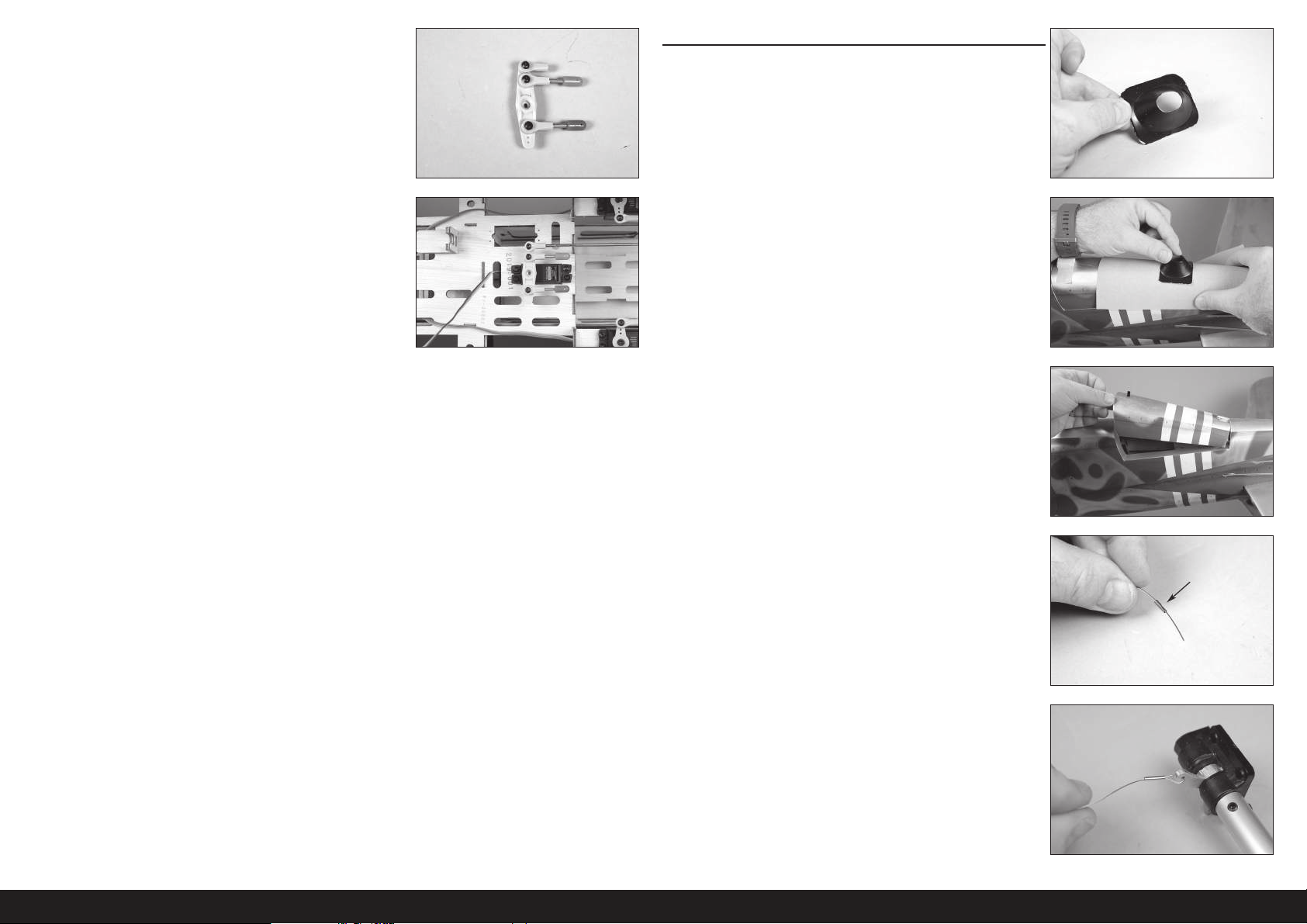
6. Ein Gelenkkopfende und zwei Gelenkkopfenden mit
Kabelverschraubung am Servoarm des Seitenruders anbringen. Drei
M3x10 Rundkopfschrauben, drei M3 Unterlegscheiben und drei M3
Kontermuttern verwenden. Mit einem 2,5mm Sechskant und einem
5,5mm Steckschlüssel die Hardware festziehen.
MONTAGE DES SPORNRADS
1. Mit einer Hobbyschere die Spornradverkleidung trimmen.
Die Montage der Spornradverkleidung ist optional.
7. Das Gestänge in das Gelenkkopfende auf dem Servoarm schrauben.
Das Gestänge bei eingeschaltetem Funksystem anpassen, so dass
das Seitenruder zentriert ist, wenn sich der Arm auf dem Servo
befi ndet. Die Schraube des Servoarms zum jetzigen Zeitpunkt nicht
montieren.
2. Sandpapier mittlerer Körnung gegen den Rumpf halten. Die
Spornradverkleidung leicht schleifen, um zur Form des Rumpfs zu
passen.
3. Die Verriegelung zur Hinterseite des Rumpfs schieben und die
Spornradverkleidung entfernen. Die Abdeckung zur Seite legen.
4. Eine Manschette auf das Kabelende schieben.
5. Das Kabel durch das Loch im Spornradarm führen. Das Kabel zurück
durch die Manschette führen.
58DE
Page 59
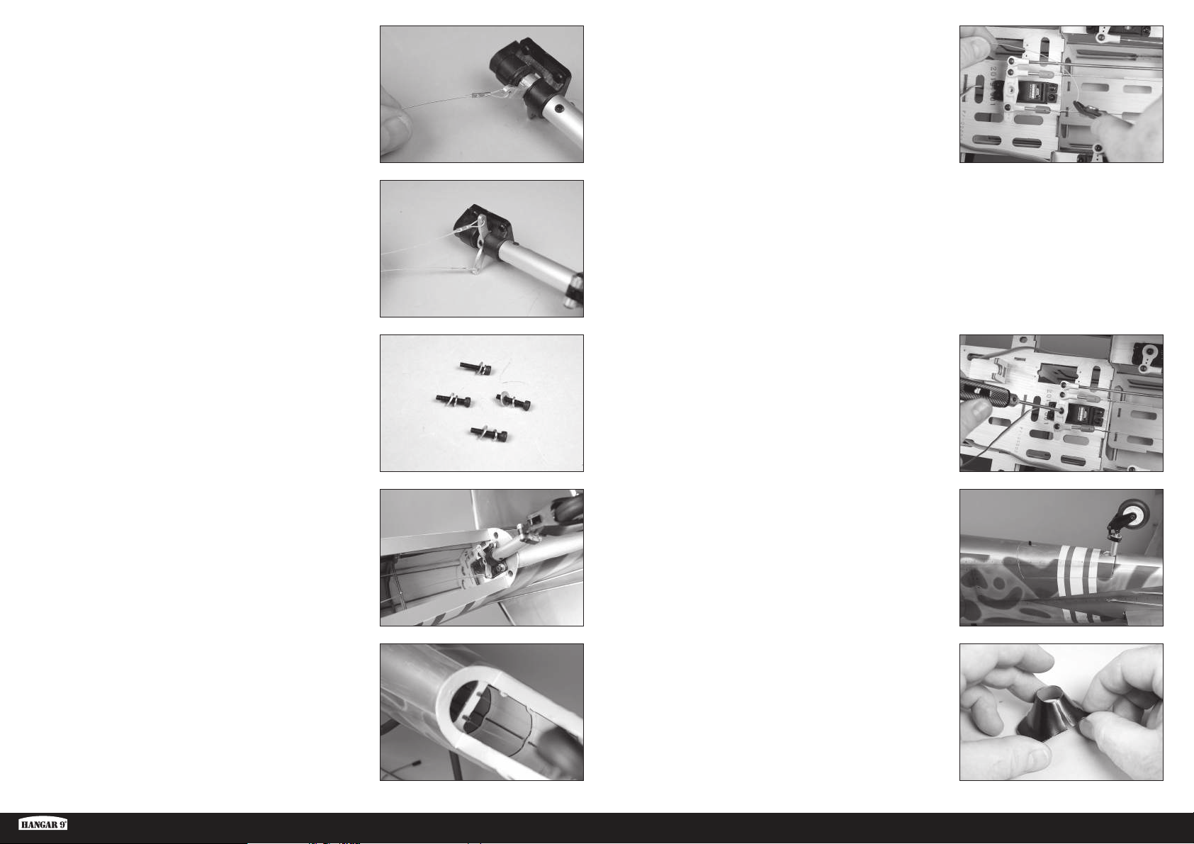
6. Mit einer Crimpzange die Manschette am Kabel sichern.
Darauf achten, keinen übermäßigen Druck auszuüben und die
Manschette abzuschneiden, anstatt diese am Kabel zu befestigen.
11. Eine Manschette auf das Kabelende schieben. Das Kabel durch das
Loch in der Kabelverschraubung führen. Das Kabel zurück durch die
Manschette führen. Bei zentriertem Querruder-Servo und Spornrad,
eine leichte Spannung auf das Kabel bringen. Mit einer Crimpzange
die Manschette am Kabel sichern.
Der Servoarm kann bei Bedarf vom Servo entfernt werden.
Darauf achten, nicht zu stark zu drücken und die Kräuselung
abzuschneiden, anstatt am Kabel zu befestigen.
7. Diesen Vorgang zur Befestigung des verbleibenden Kabels am
Spornradarm wiederholen.
8. Eine M3 Sicherungsscheibe, dann eine M3 Unterlegscheibe auf
eine M3x15 Zylinderkopfschraube schieben. Alle vier Schrauben
vorbereiten.
9. Einen Tropfen Gewindekleber auf jede Schraube auftragen. Die
Spornradhalterung mit den Schrauben aus dem vorherigen Schritt
und einem 2,5mm Sechskant im Rumpf sichern.
Diesen Vorgang zum Sichern beider Kabel wiederholen.
Die Kabel können sich im Laufe der Zeit leicht dehnen.
Die Kabel regelmäßig überprüfen, um sicherzustellen,
dass sie immer noch leicht gespannt sind.
Mit einem Seitenschneider die überstehenden Kabel trimmen, die den
Betrieb des Modells beeinträchtigen können.
12. Den Servoarm des Seitenruders mit der mit dem Seitenruder
mitgelieferten Schraube sichern.
13. Die Spornradabdeckung am Rumpf anbringen.
10. Die Kabel in die Rohre im Rumpf schieben. Die Kabel innerhalb des
Rumpfs zurückholen.
Ki-43 Oscar 60cc ARF
14. Mit einer Hobbyschere einen Schlitz in die Verkleidung schneiden,
damit diese über die Spornradbaugruppe platziert werden kann.
59 DE
Page 60
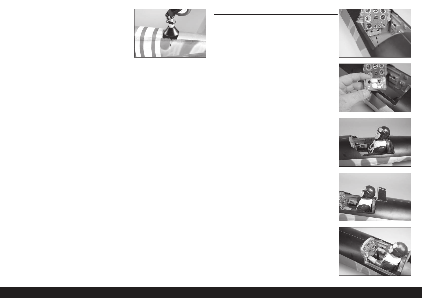
15. Die Spornradverkleidung mit Kontaktkleber an die
Spornradabdeckung kleben. Darauf achten, die Abdeckung nicht
an den Rumpf zu kleben, falls die Abdeckung für den Zugang zum
Spornrad entfernt werden muss.
MONTAGE VON PILOT UND KANZEL
1. Zum Einpassen des Piloten in das Cockpit muss der untere Teil der
Instrumententafel entfernt werden.
Bei Produktionsmodellen muss der untere Teil der
Instrumententafel nicht unbedingt entfernt werden.
2. Die untere Instrumententafel mit einem Hobbymesser und einer
Klinge Nr.11 vorsichtig entfernen.
3. Den Piloten mit Kontaktkleber im Cockpit befestigen. Der Klebstoff
muss vor dem Fortfahren vollständig ausgehärtet sein.
4. Die Kopfstütze mit mittlerem CA-Klebstoff oder Kontaktkleber in
Position festkleben.
5. Den Steuerknüppel im Cockpit mit mittlerem CA-Klebstoff oder
5-minütigem Epoxid kleben. Den Steuerknüppel nahe der Hand des
Piloten positionieren, falls dieser montiert wurde.
60DE
Page 61
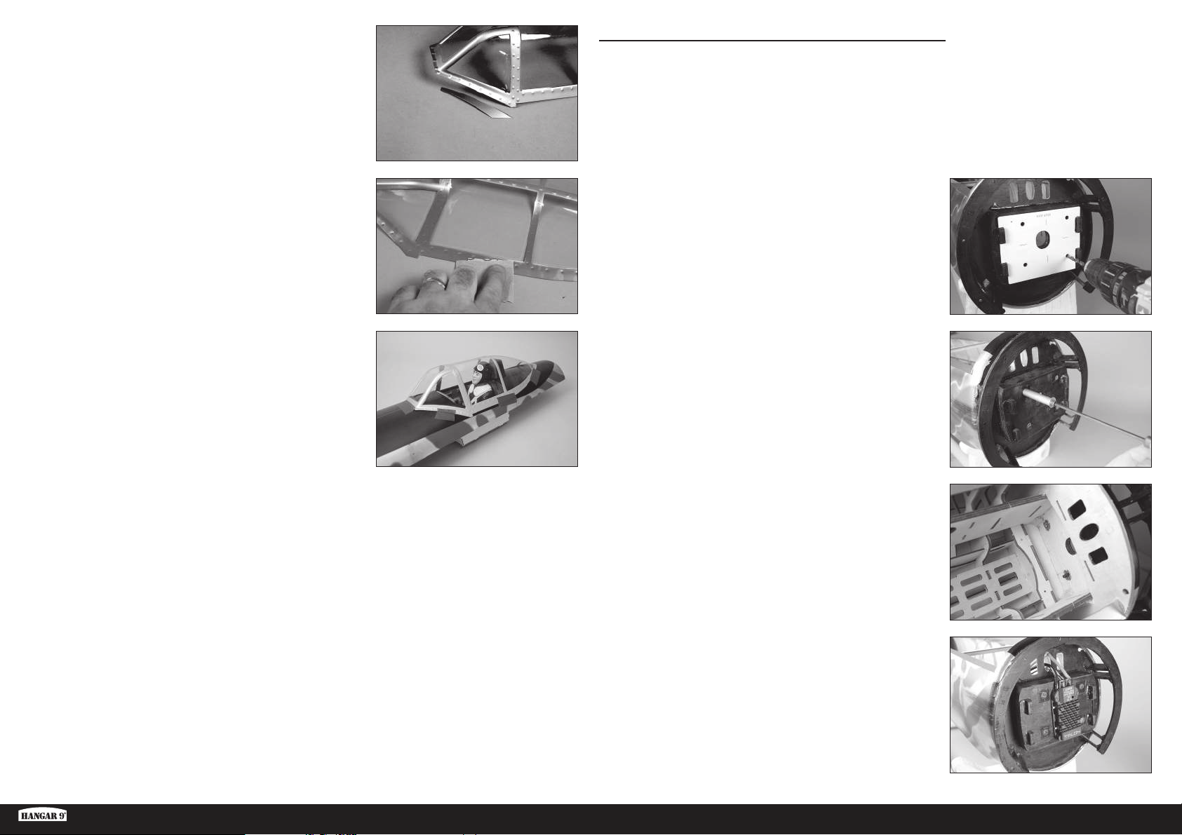
6. Überschüssiges Material muss unter Umständen von der Kanzel
entfernt werden. Mit einer Hobbyschere die Kanzel trimmen, dann
mit Sandpapier mittlerer Körnung die Kanten glätten.
MONTAGE DES ELEKTROMOTORS
Wie bei vielen maßstabsgetreuen Militärflugzeugen kommt es
auch bei der Ki-43 Oscar zu kurzen kopflastigen Momenten.
Es kann abhängig vom verwendeten Stromversorgungssystem
notwendig sein, ein Buggewicht hinzuzufügen. Dies beim
Zusammenbau im Hinterkopf behalten, um alle Komponenten
so weit vorne wie möglich im Rumpfs zu halten.
7. Die Innenkanten der Kanzel leicht mit mittelgrobem Schleifpapier
schleifen, wo diese die Kanzelabdeckung berührt. Den mit
Sandpapier bearbeiteten Bereich mit einem Papiertuch und
Isopropylalkohol von Schmutz und Öl reinigen. Dadurch wird eine
Oberfl ächentextur geschaffen, die zur Verbindung mit dem Klebstoff
notwendig ist.
8. Mit Kanzelkleber oder Kontaktkleber die Kanzel an die
Kanzelabdeckung kleben. Klebeband verwenden, um die Kanzel in
Position zu halten, bis der Kontaktkleber vollständig ausgehärtet ist.
Beim Kleben der Kanzel keinen CA-Kleber verwenden. Beim
Aushärten des CA-Klebers werden Gase freigesetzt, die die
Kanzel beschlagen und vom Erscheinungsbild ablenken.
1. Die Befestigungsplatte auf dem Brandschott platzieren. Mit
Klebeband geringer Klebekraft die Vorlage in Position halten. Mit
einem 6mm (1/4Zoll) Bohrer vier Löcher in das Brandschott bohren,
um den Motor anzubringen.
Bei Verwendung anderer Stromversorgungssysteme als der
empfohlenen Optionen empfehlen wir, die Montageschablone
als Test zu verwenden, um die vollständige Ausrichtung der
Löcher vor dem Bohren den Brandschott sicherzustellen.
2. Mit den Schrauben und Abstandsbolzen die Blindmuttern von der
Innenseite des Rumpfs in den Brandschott zu ziehen.
Ki-43 Oscar 60cc ARF
3. Bei Bedarf die Anschlüsse verlöten, um den Geschwindigkeitsregler
an Motor und Akku anzuschließen. Den Geschwindigkeitsregler mit
Schrauben oder Kabelbindern am Brandschott sichern.
61 DE
Page 62
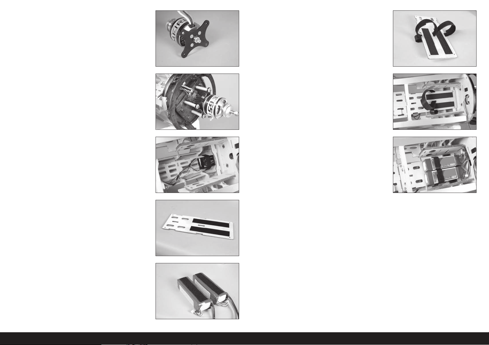
4. Die Halterung mit der dem Motor beiliegenden Hardware am
Motor befestigen. Einen Tropfen Gewindekleber auf jeder Schraube
verwenden, um ein Lösen unter Vibrationen zu verhindern.
9. Klettbänder um die Akkuhalterung verwenden, um die Akkus in der
Halterung zu sichern.
Eine kleine Menge 5-minütiges Epoxid auf die Bänder auftragen,
um sie an der Akkuhalterung zu sichern. Hierdurch wird vermieden,
dass diese durch die Löcher fallen, wenn der Akku entfernt wird.
5. Den Motor mit den Aluminium-Abstandsbolzen und Schrauben am
Brandschott befestigen. Einen Tropfen Gewindekleber auf jeder
Schraube verwenden, um ein Lösen unter Vibrationen zu verhindern.
Die Leitungen zwischen Geschwindigkeitsregler und Motor
anschließen. Die Leitungen sichern, sodass sie den Betrieb des
Motors nicht beeinträchtigen.
6. Den Akku für das Funksystem im unteren Bereich des Rumpfs
sichern. Den Akku mit Klettband oder Klettbändern sichern.
7. Eine dünne Schicht 5-minütigen Epoxid auf der Akkuhalterung
auftragen, wo das Klettband angebracht wird. Den Epoxid vollständig
aushärten lassen, ehe das Klettband an der Akkuhalterung
angebracht wird.
Der Klebstoff auf dem Klettband wird nicht am Rohholz
haften. Durch Epoxid wird eine Oberfläche geschaffen,
die für den Klebstoff des Klettbands geeignet ist.
10. Die Löcher im Rumpf für die Schrauben der Akkuhalterung mit
M3x15 Blechschrauben und dünnem CA-Klebstoff vorbereiten und
härten. Die Akkuhalterung mit vier M3x15 Blechschrauben und vier
M3 Unterlegscheiben im Rumpf sichern.
11. Die Akkus mit den Klettbändern im Rumpf sichern. Die Position der
Akkus kann zum Ausbalancieren des Modells verschoben werden.
8. Das anhaftende Klettband an den Akkus befestigen.
Die Sicherheitshinweise auf dem Akku nicht
mit dem Klettband verdecken.
62DE
Page 63
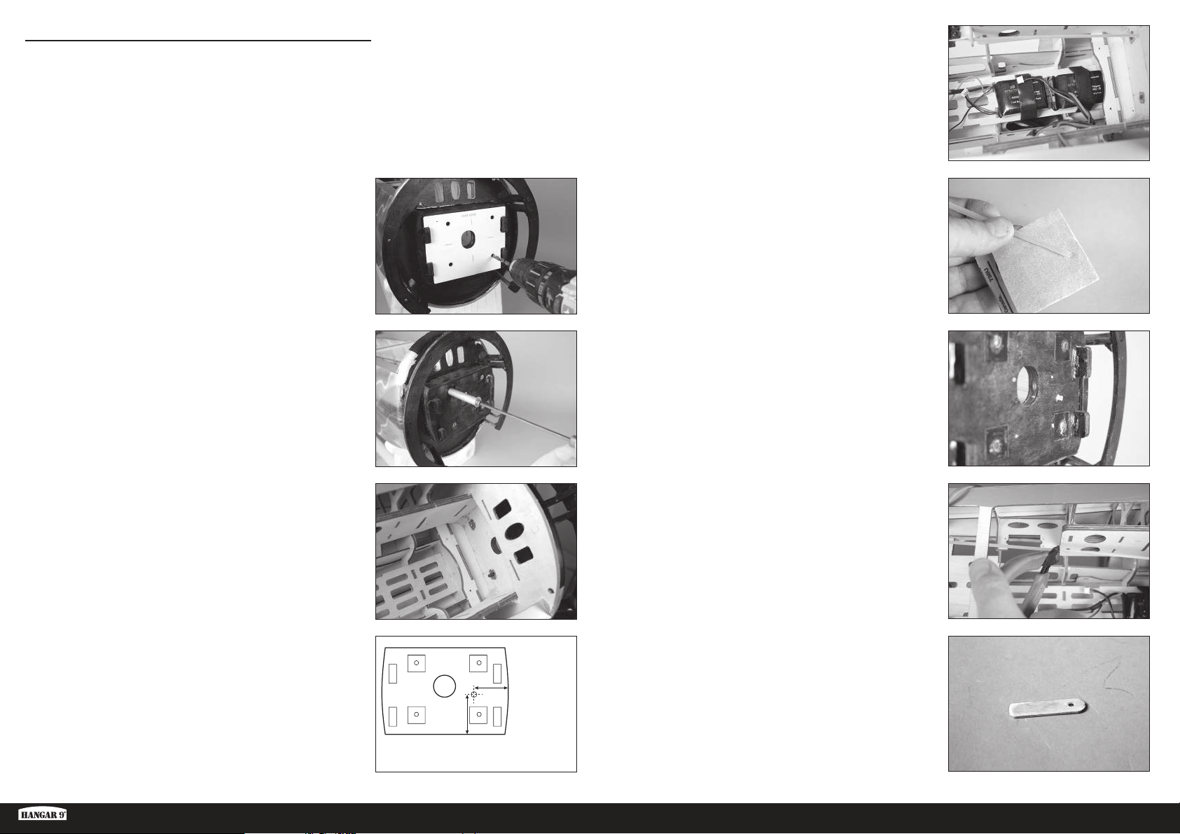
MONTAGE DES BENZINMOTORS
Wie bei vielen maßstabsgetreuen Militärflugzeugen kommt es
auch bei der Ki-43 Oscar zu kurzen kopflastigen Momenten.
Es kann abhängig vom verwendeten Stromversorgungssystem
notwendig sein, ein Buggewicht hinzuzufügen. Dies beim
Zusammenbau im Hinterkopf behalten, um alle Komponenten
so weit vorne wie möglich im Rumpfs zu halten.
4. Die Akkus für das Funksystem und die Zündung im unteren Bereich
des Rumpfs sichern. Die Akkus mit Klettband oder Klettbändern
sichern.
1. Die Befestigungsplatte auf dem Brandschott platzieren. Mit
Klebeband geringer Klebekraft die Vorlage in Position halten. Mit
einem 6mm (1/4Zoll) Bohrer vier Löcher in das Brandschott bohren,
um den Motor anzubringen.
Bei Verwendung anderer Stromversorgungssysteme als der
empfohlenen Optionen empfehlen wir, die Montageschablone
als Test zu verwenden, um die vollständige Ausrichtung der
Löcher vor dem Bohren den Brandschott sicherzustellen.
2. Mit den Schrauben und Abstandsbolzen die Blindmuttern von der
Innenseite des Rumpfs in den Brandschott zu ziehen.
5. Mit Sandpapier mittlerer Körnung das Gestängerohr leicht
schleifen. Mit einem Papiertuch und Isopropylalkohol Öl und
Schmutzrückstände vom Rohr entfernen.
6. Das Rohr in das Loch im Brandschott schieben. 6mm (1/4 Zoll) des
Rohrs aus dem Brandschott herausragen lassen. Mit mittelstarkem
CA-Klebstoff das Rohr fi xieren.
7. Mit einem Seitenschneider das Gestängerohr 5mm (3/16Zoll) hinter
der Kante der inneren Rumpfseite trimmen.
3. Mit einem 3,5mm (9/64Zoll) Bohrer das Loch für das Gasgestänge
bohren.
Die abgebildete Position ist für den Evolution 62GX.
Sicherstellen, dass das Gasrohr beim Einsatz
anderer Motoren korrekt lokalisiert wurde.
Ki-43 Oscar 60cc ARF
23/32 inches
(53mm)
121/32 inches
(42mm)
8. Mit einem 3,5mm (9/64Zoll) Bohrer ein Loch in einen Rührstab
bohren. Den Stab auf eine Länge von 38mm (1
1
/2 Zoll) schneiden.
Dies wird der hintere Träger für das Gasgestängerohr.
63 DE
Page 64
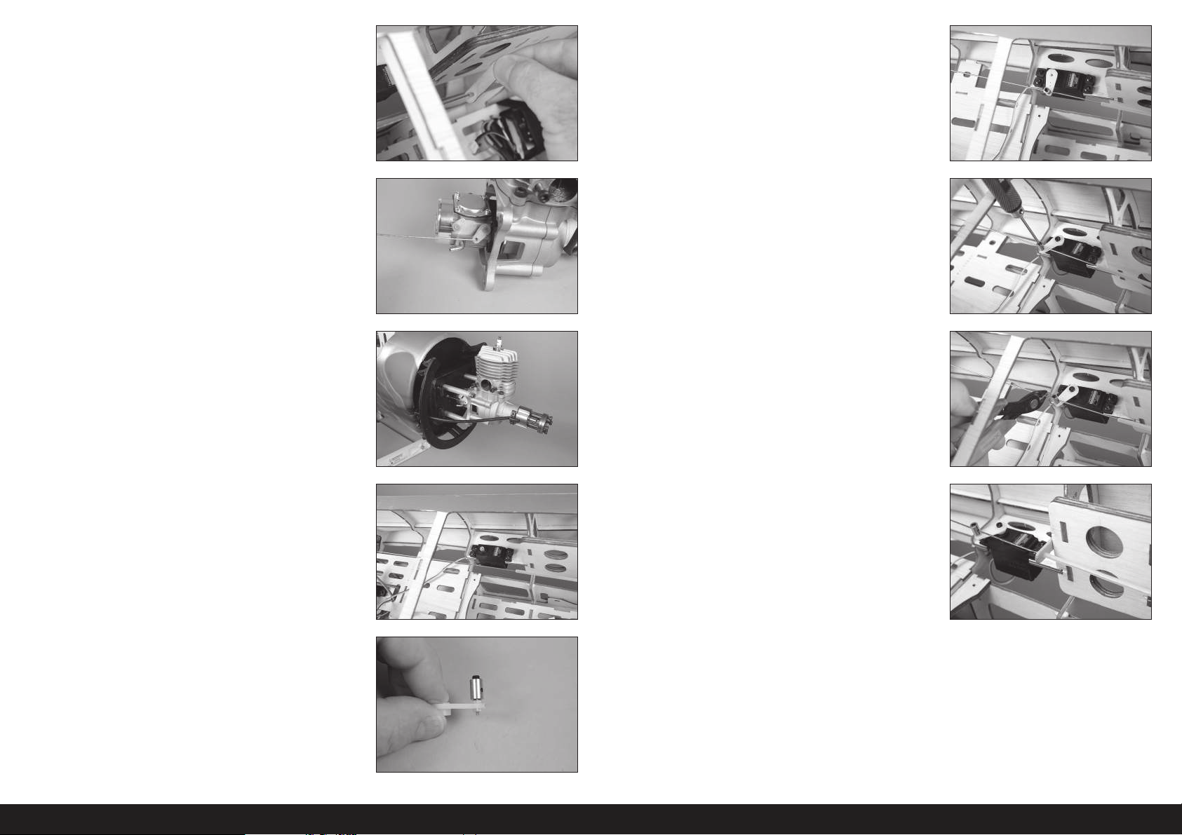
9. Den Träger auf das Gestängerohr schieben. 14. Das Servo mit dem Funksystem zentrieren und den Servoarm
auf dem Servo senkrecht zur Mittellinie des Servos montieren.
Sicherstellen, den Stecker auf den Gestängedraht zu schieben. Mit
einem Seitenschneider alle Arme entfernen, die den Betrieb des
Servos beeinträchtigen können.
10. Die Z-Krümmung mit dem Gestänge im Vergaserarm verbinden. 15. Vergaser und Servo auf niedrigere Gaszufuhr stellen und die
Feststellschraube festziehen, die das Gestänge am Steckverbinder
am Servo sichert. Mit einem Seitenschneider den überstehenden
Draht trimmen. Den Betrieb des Vergasers mit dem Funksystem
prüfen. Alle erforderlichen Einstellungen vornehmen, um den
Vergaser über das Radiosystem vollständig zu öffnen und zu
schließen.
11. Das Gasgestänge in das Gestängerohr führen. Den Motor mit vier
Abstandhaltern, vier Maschinenschrauben und vier Unterlegscheiben
am Brandschott anbringen. Einen Tropfen Gewindekleber vor der
Montage auf das Ende jeder Schraube auftragen.
12. Die Löcher im Rumpf für den Gas-Servo vorbereiten, indem eine
Schraube in jedes Loch geschraubt wird. Die Schrauben entfernen
und 2 bis 3 Tropfen dünnen CA-Klebstoff in jedes Loch geben, um
das umgebende Holz zu härten. Nach dem Aushärten des CAKlebstoffs den Gas-Servo montieren, wobei die Servowelle zur
Rückseite des Rumpfs weist.
13. Den Gas-Servo-Steckverbinder im Gas-Servoarm montieren, sodass
er 11mm (7/16Zoll) von der Mitte des Servoarms entfernt liegt.
Einen Tropfen Kanzelkleber auf die M2 Mutter geben und diese dann
auf der Unterseite des Arms montieren, um den Steckverbinder zu
fi xieren.
16. Mit einem Seitenschneider den überstehenden Gestängedraht
entfernen, der den Betrieb des Gas-Servos beeinträchtigen kann.
17. Mit 15-minütigem Epoxid den Gestängerohrträger an die Hinterkante
der inneren Rumpfseite kleben.
64DE
Page 65
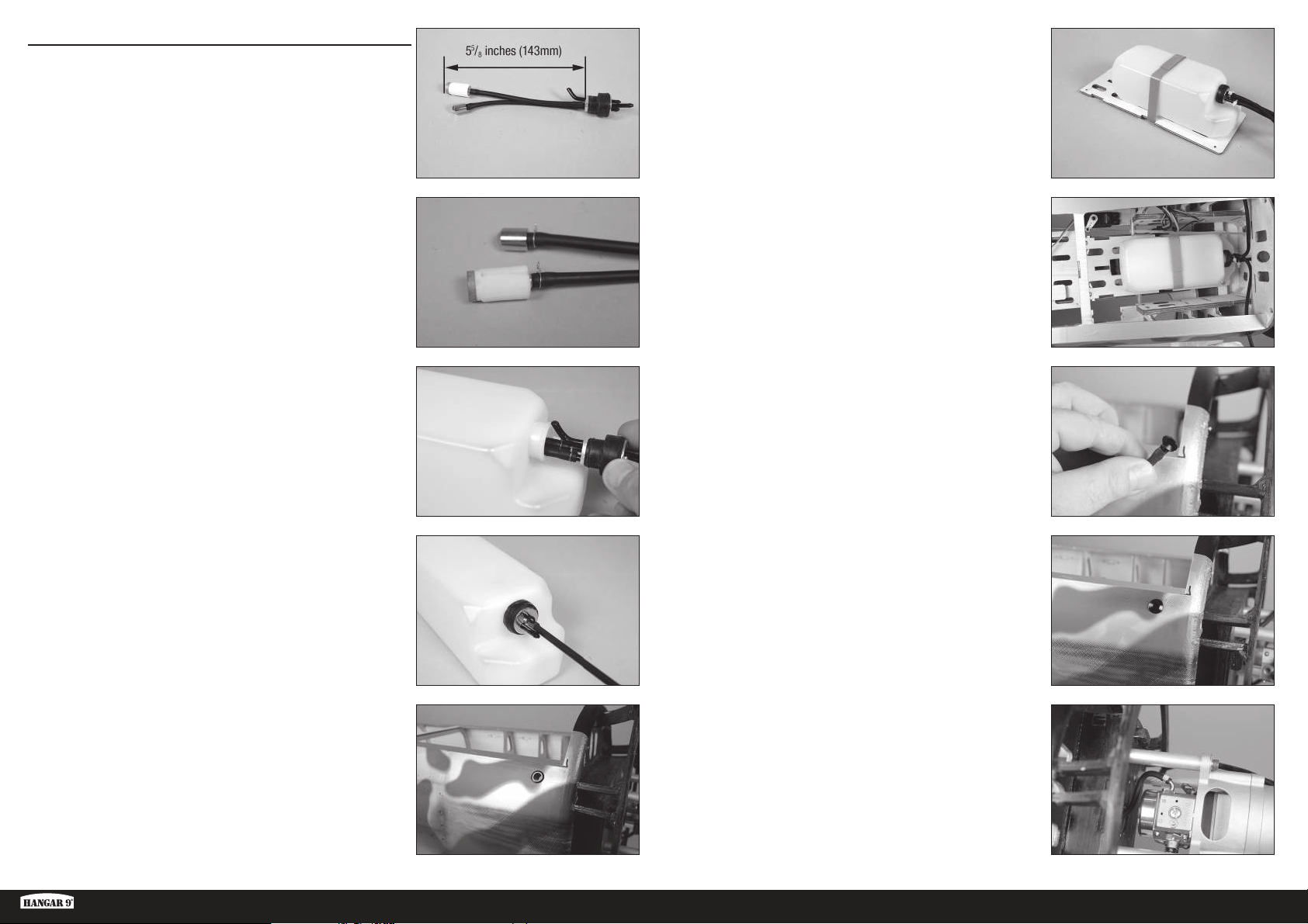
MONTAGE DES KRAFTSTOFFTANKS
1. Einen Teil der Kraftstoffl eitung schneiden, wodurch das Ende des
Pendels 143mm (55/8 Zoll) von der Rückseite der Aluminiumplatte
ist.
6. Den Kraftstofftank mit Klettband in der Halterung des Kraftstofftanks
sichern 190mm (7
1
/2 Zoll) lange Stücke der Kraftstoffl eitung an den
drei Leitungen sichern, die den Tank verlassen. Mit Kabelbindern
sichern, um ein Verrutschen der Leitungen zu verhindern.
2. Das Rohr mit einem dünnen Draht an Pendel und Verschluss
sichern. Dadurch wird ein Verrutschen des Rohrs innerhalb des
Kraftstofftanks verhindert. Darauf achten, das mit dem Motor
mitgelieferte Pendel zu verwenden.
Ein zweites Pendel kann montiert werden, um eine Leitung
zum Füllen/Entleeren des Fluggeräts bereitzustellen.
Wir empfehlen die Verwendung eines Pendels mit
einem Filter für sämtliche Motormontagen.
3. Die Pendel in den Kraftstofftank einführen. Erst das große Pendel
und dann das kleinere Pendel montieren. Die Entlüftungsleitung wird
zur Oberseite des Kraftstofftanks weisen.
4. Die Leitungen am Tank markieren, damit die Kraftstoffl eitungen
außerhalb des Kraftstofftanks erkannt werden können. Die Schraube
im Verschluss mit einem Kreuzschlitzschraubendreher Nr.1
festziehen.
Prüfen, ob sich beide Pendel im Kraftstofftank frei bewegen
können. Ist dies nicht der Fall, die Leitungen außerhalb des
Tanks anpassen, damit sich diese frei bewegen können, um so
einen gleichmäßigen Kraftstofffluss zum Motor sicherzustellen.
7. Die Löcher im Rumpf für die Schrauben der Halterung des
Kraftstofftanks mit M3x15 Blechschrauben und dünnem CAKlebstoff vorbereiten und härten. Die Halterung des Kraftstofftanks
mit vier M3x15 Blechschrauben und vier M3 Unterlegscheiben im
Rumpf sichern.
8. Die Füllleitung durch das Fitting im Rumpf führen. Den Einfüllstopfen
in die Füllleitung vom Tanks einführen.
9. Den Stopfen in das Fitting drücken, um die Füllleitung zu sichern. Die
Entlüftungsleitung vom Tank zum Boden des Rumpfs verlegen. Die
Entlüftungsleitung mit einem Fitting unterhalb des Rumpfs sichern.
5. Mit einem Hobbymesser mit einer Klinge Nr.11 die Abdeckung vom
Rumpf entfernen, um die Füllleitung einzupassen. Die Einpassung im
Rumpf montieren.
Die Füllleitung kann außerdem außerhalb der Rumpfs
verbleiben, um das maßstabsgetreue Aussehen des
Modells beizubehalten. Die Kanzelabdeckung muss entfernt
werden, um dem Kraftstofftank Kraftstoff zuzuführen.
Ki-43 Oscar 60cc ARF
10. Die Leitung vom gefi lterten Pendel am Vergaser anschließen. Mit
einem Kabelbinder den Leitung am Vergaser sichern.
Einen Filter zwischen Kraftstofftank und Vergaser verwenden,
um ein Eindringen möglicher sich im Kraftstoff befindlichen
Rückstände in den Vergaser und Motor zu verhindern.
65 DE
Page 66
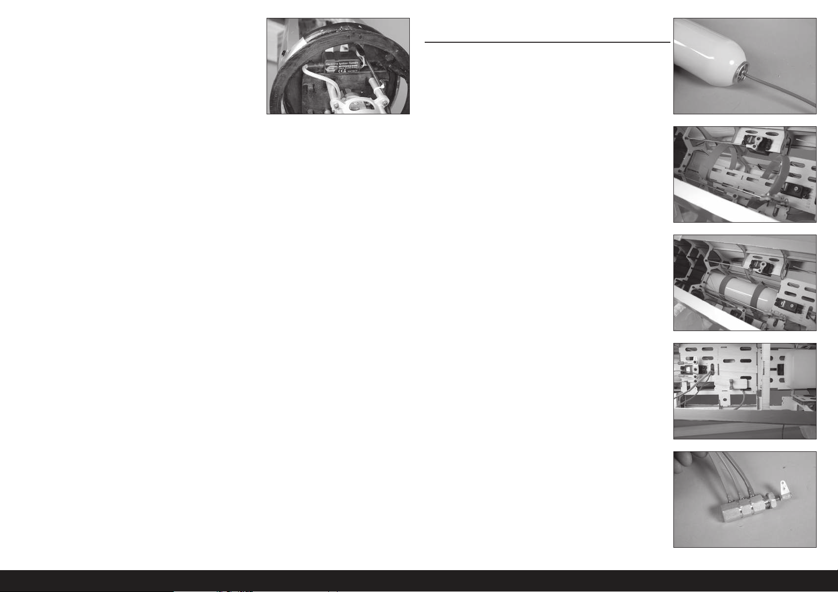
11. Das Zündmodul am Brandschott befestigen. Die mit dem Motor
mitgelieferten Anweisungen zum Anschließen des Moduls an Motor
und Zünd-Akku verwenden.
MONTAGE DES LUFTSYSTEMS DES EINZIEHBAREN
FAHRWERKS
1. Ein 305mmm (12Zoll) großes Stück der Luftleitung zuschneiden
und am Lufttank anbringen.
Mit einer Heißluftpistole auf schwacher Hitze die Luftleitungen
leicht weich machen, damit sie durch die Fittings passen.
2. Den Servoarm vom Seitenruder-Servo entfernen. Bänder um den
Tank im Rumpf platzieren.
3. Eine kleine Menge Kontaktkleber auf der Halterung auftragen. Den
Lufttank im Rumpf mit Bändern sichern.
4. Die Luftleitung unter der Servo-Halterung zur Position des Luftventils
verlegen.
5. Zwei 102mm (4 Zoll) große Stücke der orangefarbenen Luftleitung
und ein 102mm (4Zoll) großes Stück der blauen Luftleitung
zuschneiden. Die orangefarbene Luftleitung am Fitting nahe den
Endstücken und Mittelstücken des Luftventils anbringen und die
blaue Luftleitung am Fitting nahe des Stellantriebs.
Den Stellantrieb nicht vom Ventilkörper trennen, da dies die
O-Ringe beschädigt und einen Luftaustritt im Ventil verursacht.
Mit einer Heißluftpistole auf schwacher Hitze die Luftleitungen
leicht weich machen, damit sie durch die Fittings passen.
66DE
Page 67
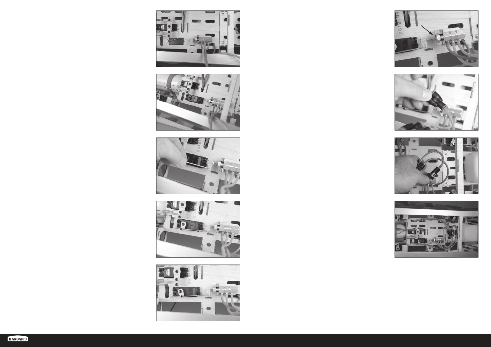
6. Das Luftventil im Rumpf sichern. Mit einem 14mm Steckschlüssel
die Mutter festziehen, um so das Ventil zu sichern.
11. Den Schalter am Funkgerät hin und herschalten, um den Ausschlag
langsam zu erhöhen, bis die Kante des Stellantriebs bündig mit der
Kante des Ventilkörpers liegt.
Sicherstellen, den Stellantrieb nicht aus dem Ventilkörper
zu ziehen und die O-Ringe zu beschädigen.
7. Die Löcher im Rumpf für das Ventil des Einfahr-Servos vorbereiten,
indem eine Schraube in jedes Loch geschraubt wird. Die Schrauben
entfernen und 2 bis 3 Tropfen dünnen CA-Klebstoff in jedes Loch
geben, um das umgebende Holz zu härten. Nach dem Aushärten des
CA-Klebstoffs das Ventil des Einfahr-Servos montieren, wobei die
Servowelle zur Rückseite des Rumpfs weist.
8. Die Z-Krümmung des Gestänges des Ventils des einziehbaren
Fahrwerks durch das Loch im Stellantrieb einführen.
9. Den Servo-Steckverbinder im Servoarm montieren, sodass er
9mm (11/32Zoll) von der Mitte des Servoarms entfernt liegt. Einen
Tropfen Kanzelkleber auf die M2 Mutter geben und diese dann
auf der Unterseite des Arms montieren, um den Steckverbinder zu
fi xieren. Die Ausschläge für den Einfahr-Servo in beide Richtungen
auf 0% einrichten. Den Stellantrieb so nah an der Mitte wie möglich
zentrieren, dann die Feststellschraube zum Sichern des Gestänges
im Stecker festziehen.
12. Ein Y-Stück am Rohr von der Mitte des Ventils anschließen. Die
Luftleitung vollständig in das Fitting drücken.
Die Luftleitungen können entfernt werden, indem die
Schulter gegen den Körper des Fittings gedrückt wird
und die Luftleitungen herausgezogen werden.
13. Ein 51mmm (2Zoll) großes Stück der Luftleitung zuschneiden
und am Füllventil anschließen. Der Pfeil wird auf das Fitting/Ventil
weisen. Die Leitung vom Lufttank am Fitting anbringen.
Der Pfeil zeigt den Luftfluss von der externen Füllpumpe
zum Einziehsystem an. Innerhalb des Ventils gibt es ein
Rückschlagventil, das die Luft daran hindert, in die andere
Richtung zu strömen und den Lufttank zu entleeren.
14. Die verbleibenden Y-Stücke für die Hin- und Rückleitungen der
Luft anschließen. Farbige Luftleitungen verwenden, die denen vom
Ventil entsprechen, um den Betrieb der einziehbaren Fahrwege
abzugrenzen. Die Luftleitungen in den Rumpf entlang der Kante der
Funksystemhalterung in Richtung der Öffnungen für die Tragfl äche
verlegen. Alle Luftleitungen und Fittings im Rumpf sichern. Fittings
am Ende der Luftleitungen anbringen, um die Luftleitungen von den
einziehbaren Fahrwerken in den Tragfl ächen anzuschließen.
Der Ausschlag muss für den Betrieb des Ventils nicht
groß sein. Sicherstellen, das Ventil durch einen zu
großen Ausschlag am Servo nicht zu beschädigen.
10. Den Servoausschlag am Funksystem langsam erhöhen, um den
Stellantrieb in das Ventil zu verschieben. Sicherstellen, dass der
Stellantrieb den Boden nicht berührt und das Ventil beschädigt.
Ki-43 Oscar 60cc ARF
Es ist bei den steckbaren pneumatischen Anschlüssen wichtig,
sicherzustellen, dass die Luftleitung zum Versiegeln der
Luftleitungen ganz in den Luftanschluss gedrückt wird. Wird
dies unterlassen, dann kommt es zu einem Luftaustritt.
67 DE
Page 68
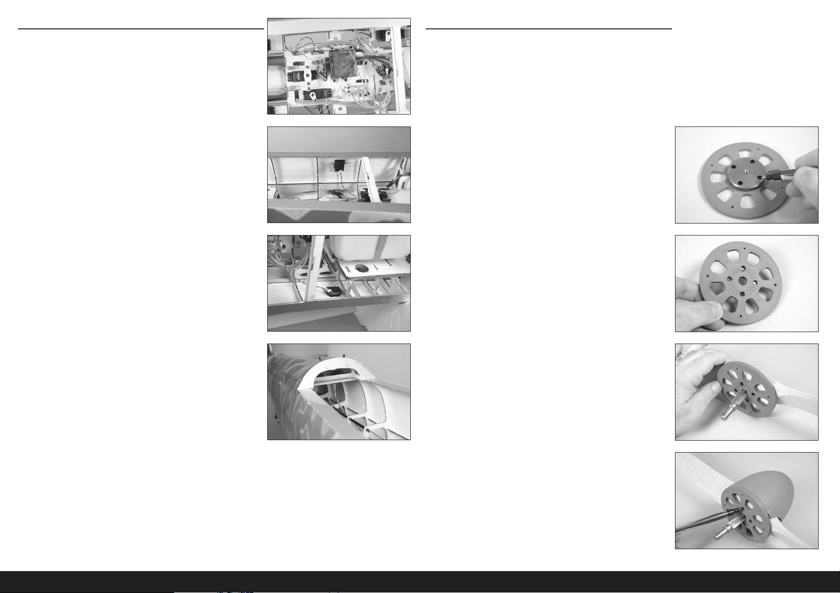
MONTAGE DES EMPFÄNGERS
MONTAGE VON MOTORHAUBE UND SPINNER
1. Den Empfänger im Rumpf montieren. Den Empfänger mit den in den
Anweisungen für den Empfänger oder das Funksystem enthaltenen
Methoden sichern.
2. Einen beliebigen Funkempfänger mit Klettband im Rumpf anbringen.
Die mit dem Empfänger bereitgestellten Anweisungen nutzen,
um die Funkempfänger im Rumpf für den optimalen Betrieb des
Empfängers ausrichten.
Eine kleine Menge 5-minütiges Epoxid auf das Klettband
auftragen, um diese im Rumpf zu sichern.
Der Spinnerkegel wurde mit Schlitzen für den Propeller vorbereitet.
Die meisten Motoren dieser Größe benötigen vier Schrauben
zum Halten des Propellers. Die vorsichtige Positionierung der
Bohrlöcher ist erforderlich, um sicherzustellen, dass der Propeller
mit den Aussparungen im Spinnerkegel ausgerichtet ist.
Wir empfehlen das Vorbereiten von mindestens zwei Propellern, falls
Sie beim Fliegen im Außenbereich einen neuen Propeller benötigen.
1. Setzen Sie die Unterlegscheibe vom Motor auf die Spinnerrückplatte.
Die Positionen für die Befestigungsschrauben des Propellers mit
einem Filzstift markieren.
2. Die Unterlegscheibe von der Rückplatte entfernen. Mit einem
5mm (7/32Zoll) Bohrer Löcher für die Befestigungsschrauben des
Propellers bohren.
Eine Standbohrmaschine wird zum Bohren der Löcher
empfohlen, um zu garantieren, dass die Löcher bei der
Montage des Propellers korrekt ausgerichtet sind.
3. Mit einer Stufenreibahle oder einer Schraube durch Spinner-
Rückplatte und Propeller diese ausgerichtet halten, damit die
Schraubenlöcher zum Anbringen des Propellers markiert werden
können.
4. Mit vier M3 x 10 Zylinderkopfschrauben den Spinnerkegel an der
Rückplatte sichern. Mit einem 3mm Sechskant die Schrauben
festziehen. Den Propeller so positionieren, dass er den Spinnerkegel
nicht berührt. Mit einem Feilkloben und 4,5mm (3/16Zoll) Bohrer
die Schraubenposition bohren und einrücken oder markieren.
Es kann notwendig sein, den Spinnerkegel
abhängig von der Propellerwahl zu trimmen, damit
sich der Propeller frei bewegen kann.
68DE
Page 69
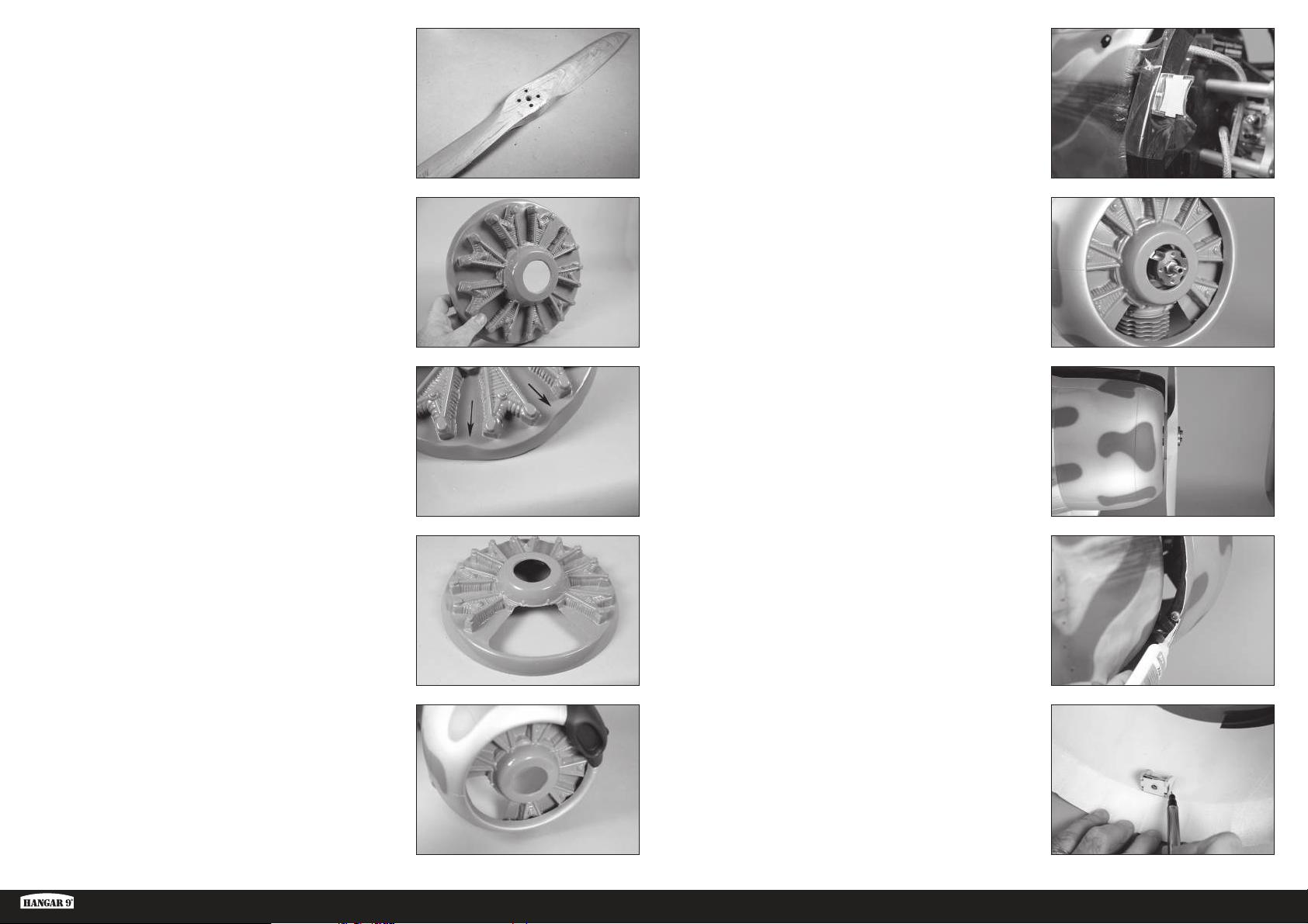
5. Den Spinner zerlegen und den Propeller entfernen. Mit einem
5mm (7/32Zoll) Bohrer die Löcher im Propeller für die
Befestigungsschrauben bohren.
Eine Standbohrmaschine wird zum Bohren der Löcher
empfohlen, um zu garantieren, dass die Löcher bei der
Montage des Propellers korrekt ausgerichtet sind.
10. Ein Stück durchsichtigem Kunststoff zwischen die Halterungen
und dem Ring der Motorhaube platzieren. Die Halterungen der
Motorhaube am Rumpf mit M4x15 Zylinderkopfschrauben,
M4 Sicherungsscheiben und M4 Unterlegscheiben sichern. Die
Halterung mit dem Motorhaubenring ausrichten und die Hardware
mit einem 3mm Sechskant festziehen.
6. Das Material in der Mitte der Motorattrappe für die Propellerwelle
und die Unterlegscheibe des Antriebs des verwendeten Motors
entfernen.
Die Motorattrappe wird unlackiert geliefert. Sie funktioniert
als Luftleitblech und hilft dabei, die Luft über den Zylinderkopf
des Gasmotors zu leiten. Wird die Motorattrappe nicht
eingepasst, so kann der Gasmotor aufgrund eines schlechten
Luftflusses durch die Öffnungen der Motorhaube überhitzen.
7. Die Oberseite des Sternmotors wird durch zwei Vertiefungen
angezeigt, die sich mit dem Austritt in der Motorhaube ausrichten.
Dies als Referenz beim Trimmen des Motors verwenden.
8. Gas: Die Motorattrappe trimmen, sodass Luft über den Motor fl ießen
kann, und um den Vergaser bei Bedarf zu reinigen.
EP: Das Material zwischen den Zylindern der Motorattrappe trimmen,
damit Kühlluft über den Motor und den Geschwindigkeitsregler
strömen kann.
Das Foto zeigt den für die Montage als
Gasmotor vorbereiteten Sternenmotor.
11. Die Motorhaube in Position schieben. Die Unterlegscheibe des
Antriebs in der Öffnung zentrieren.
12. Den Propeller anhand der dem Motor beiliegenden Hardware an der
Motorwelle befestigen. Die Motorhaube so positionieren, dass der
Propeller beim Drehen gleich weit von der Motorhaube entfernt liegt.
13. Dünnen CA-Klebstoff für das Ankleben der Halterungen an der
Motorhaube verwenden.
Die Halterungen werden für das sichere Kleben in
den nächsten Schritten entfernt. Keine übermäßige
Menge Klebstoff in diesem Schritt verwenden.
Die Motorattrappe kann durch eine entsprechende Lackierung
detailliert werden, ehe sie in der Motorhaube gesichert wird.
Sicherstellen, sämtliche Lacke an getrimmten Stücken zu testen,
um sicherzustellen, dass sie mit dem Kunststoff kompatibel sind.
9. Mit Sandpapier die Farbe von der Motorattrappe an der Stelle
entfernen, an der sie mit der Innenseite der Motorhaube in
Kontakt kommt. Hierdurch wird die Haftung des Klebstoffs an
der Motorattrappe verbessert. Mit dem 15-minütigen Epoxid den
Sternmotor in die Motorhaube kleben. Das Epoxid muss vor dem
Fortfahren vollständig ausgehärtet sein.
Ki-43 Oscar 60cc ARF
14. Die Schrauben und die Motorhaube vorsichtig vom Rumpf entfernen.
Mit einem Filzstift den Umriss der Halterungen auf die Innenseite der
Motorhaube übertragen.
69 DE
Page 70
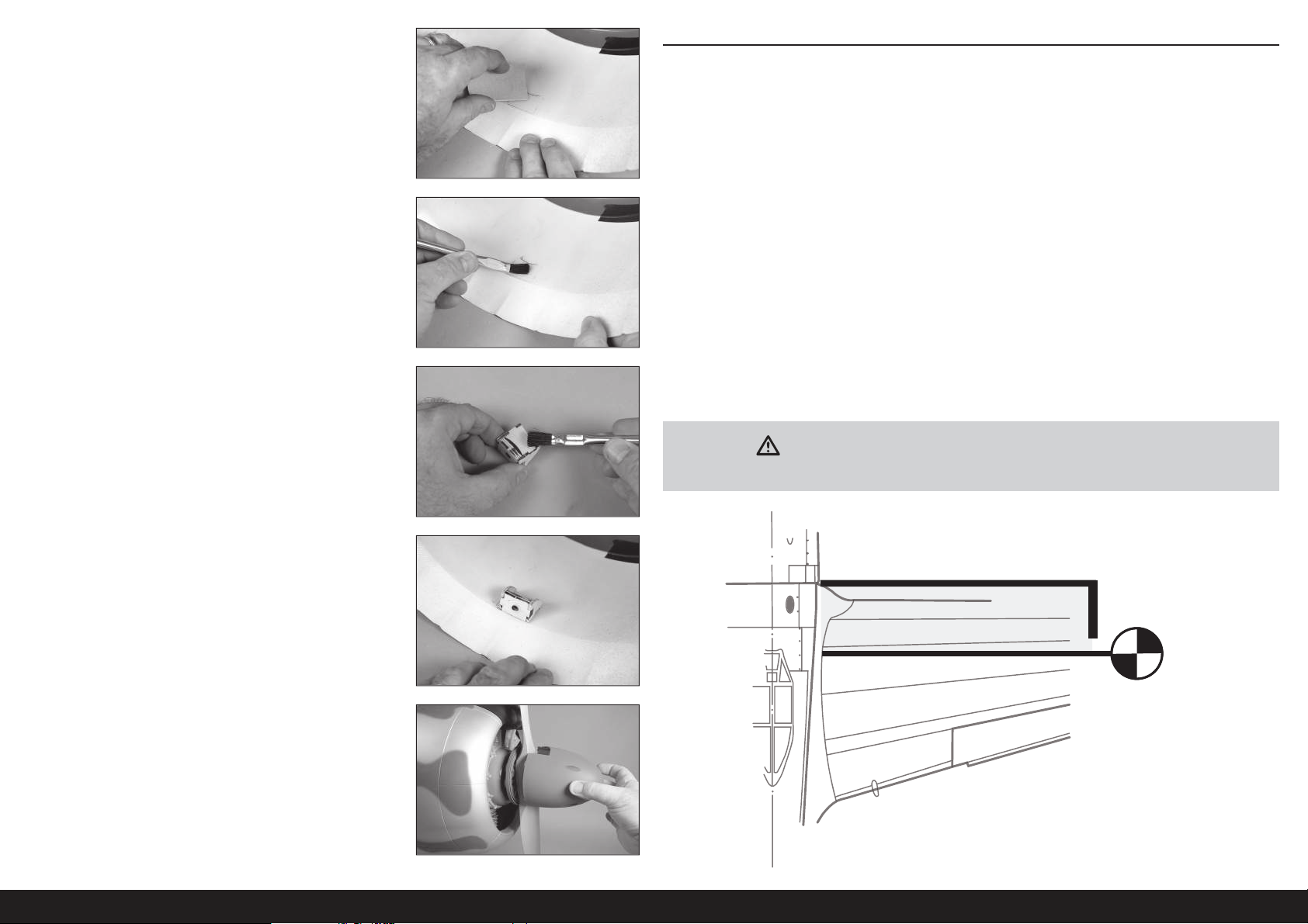
15. Die Halterungen entfernen und mit Sandpapier mittlerer Körnung
den Bereich an der Innenseite der Motorhaube, gegen den die
Halterungen anliegen, und einen Bereich von mindestens 13mm
(1/2Zoll) außerhalb des markierten Bereichs schleifen. Mit einem
Papiertuch und Isopropylalkohol Öl- oder Schmutzrückstände von
der Innenseite der Motorhaube entfernen.
Eine korrekte Vorbereitung auf das Verkleben der Halterungen ist
wichtig, um sicherzustellen, dass der Klebstoff die Halterungen
fest mit der Innenseite der Motorhaube verbinden kann.
16. 15ml (1/2 oz) 30-minütiges Epoxid mischen. Epoxid auf die
Bereiche für die Halterungen innerhalb der Motorhaube auftragen.
17. Epoxid mit einer Epoxidbürste auf die Halterungen auftragen.
SCHWERPUNKT
Ein wichtiger Teil bei der Vorbereitung des Flugzeugs für den Flug ist das ordnungsgemäße Ausbalancieren des
Modells. Der hier aufgeführte Schwerpunktbereich dient basierend auf Tests als Richtlinie. Abweichungen von
den von uns bereitgestellten Maßen ist möglich und kann zu einem Modell führen, dass besser zum eigenen
Flugstil passt. Beginnen Sie mit dem empfohlenen Schwerpunkt und experimentieren Sie dann mit verschiedenen
Gleichgewichtspunkten. Wir empfehlen ein schrittweises und vorsichtiges Anpassen.
1. Die Tragfl ächen am Rumpf anbringen. Sicherstellen, dass die Leitungen vom Querruder und Klappen an den
entsprechenden Leitungen vom Empfänger angeschlossen sind. Sicherstellen, dass die Leitungen sowie die
Luftleitungen von den einziehbaren Fahrwerken nicht außerhalb des Rumpfs liegen, ehe die Flügelschrauben
festgezogen werden. Das Modell sollte vor dem Ausbalancieren fl ugbereit sein.
2. Der empfohlene Schwerpunkt (CG) für das Modell liegt 152,5mm hinter der Vorderkante der Tragfl äche.
Diese Messung gegen den Rumpf vornehmen, dort wo der Fahrwerkschaft vor der Vorderkante der Tragfl äche
hervorragt.
3. Beim Ausbalancieren des Modells sicherstellen, dass es zusammengebaut und fl ugbereit ist. Das Flugzeug
mit den Fingern oder einem käufl ich erhältlichen Ständer aufrecht an den auf der Tragfl äche angebrachten
Markierungen abstützen.
Der CG-Gesamtbereich für dieses Modell liegt bei 140–178mm. Wir empfehlen, mit den vorstehend aufgeführten
Messwerten zu beginnen und dann die Anpassungen zum entsprechenden Flugstil vorzunehmen.
Bei der Verwendung leichterer Motoren kann Buggewicht erforderlich sein. Um das erforderliche
Gewicht zu reduzieren, die Batterien im Rumpf so weit wie möglich nach vorne bewegen.
VORSICHT: Vor einem Flug muss der Schwerpunkt des Flugzeugs ausgerichtet
und das Flugzeug ordnungsgemäß ausbalanciert sein.
18. Die Halterungen in ihre Position in der Motorhaube platzieren. Das
Epoxid muss vor dem Fortfahren vollständig ausgehärtet sein.
Eine Leiste erzeugen, die 13mm (1/2Zoll) aus den
Halterungen herausragt, um die
der Halterung und der Motorhaube zu verstärken.
19. Den Auspuff am Motor montieren. Die Motorhaube je nach Bedarf
trimmen, damit der Auspuff oder andere Bauteile des Motor, die sich
außerhalb der Motorhaube befi nden, freizulegen. Die Motorhaube
wieder auf dem Rumpf befestigen. Die Spinner-Rückplatte, den
Propeller und den Spinner am Motor montieren.
Verbindung zwischen
6 inches
(152.5mm)
70DE
Page 71
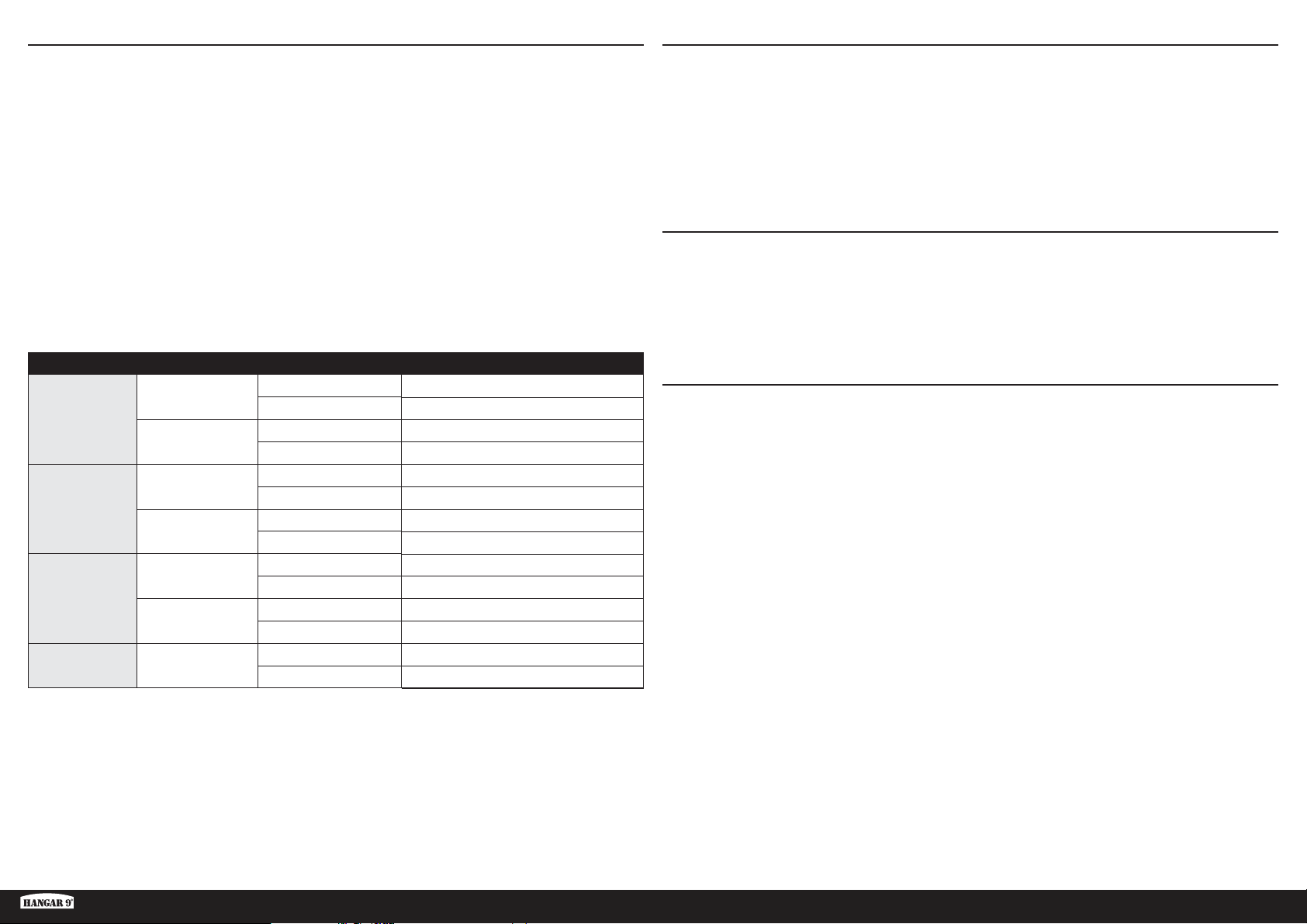
RUDERAUSSCHLAG
1. Den Sender und Empfänger des Modells einschalten. Die Bewegung des Seitenruders mit dem Empfänger prüfen.
Wird der Hebel nach rechts bewegt, sollte sich auch das Seitenruder nach rechts bewegen. Die Richtung auf dem
Servo am Empfänger bei Bedarf umkehren.
2. Die Bewegung des Höhenruders mit dem Funksystem prüfen. Wird der Hebel des Höhenruders auf dem Sender
nach unten bewegt, so bewegt sich das Höhenruder des Flugzeugs nach oben.
3. Die Bewegung des Querruders mit dem Funksystem prüfen. Wird der Hebel des Querruders nach rechts bewegt,
so bewegt sich das rechte Querruder nach oben und das linke Querruder nach unten.
4. Mit einem Lineal den Ausschlag von Höhen-, Quer- und Seitenruder einstellen.
Dies sind allgemeine Richtlinien für den allgemeinen Sport- und Kunstfl ug, die von unseren eigenen Testfl ügen
stammen. Sie können mit höheren oder niedrigeren Werten experimentieren, die zu Ihrem bevorzugten Flugstil passen.
Wegverstellung und Ersatztrimmungen sind nicht aufgeführt und sollten entsprechend dem Einzelmodell und Vorlieben
eingestellt werden. Die Steuerhörner immer im Winkel von 90° zur Mittellinie des Servos montieren. Ersatztrimmungen
als letzten Ausweg zur Zentrierung der Servos verwenden.
Oberfl äche Rate Richtung Ausschlag
20 mm
15 mm
13 mm
10 mm
50 mm
30 mm
50–60 mm
Querruder
Höhenruder
Seitenruder
Flaps
Hoch
Niedrig
Hoch
Niedrig
Hoch
Niedrig
Nach oben
Nach unten 15 mm
Nach oben
Nach unten 13 mm
Nach oben
Nach unten 13 mm
Nach oben
Nach unten 10 mm
Links
Rechts 50 mm
Links
Rechts 30 mm
Start 25–30 mm
Landen
VORFLUGKONTROLLE
• Akkus für Sender, Empfänger und Motor aufl aden. Die dem Ladegerät beigelegten Anweisungen befolgen. Die
Anweisungen des Herstellers der elektrischen Bauteile befolgen.
• Überprüfen Sie die Montage des Funkgeräts und stellen Sie sicher, dass sich alle Steuerfl ächen (Querruder,
Höhenruder, Ruder und Klappen) korrekt bewegen (d.h. in die richtige Richtung und mit den empfohlenen
Ausschlägen).
• Überprüfen Sie alle Teile der Anlenkungen (Ruderhörner, Servohebel und Gabelköpfe) und stellen sicher dass diese
gut befestigt und in einwandfreiem Zustand sind.
• Lassen Sie den Motor laufen. Wiederholen Sie mit laufenden Motor den Reichweitencheck. Die Reichweite sollte
nicht signifi kant beeinfl ußt werden.
TÄGLICHER FLUG CHECK
• Überprüfen Sie die Spannung des Senderakkus. Fliegen Sie nicht wenn die Spannung unterhalb der vom Hersteller
empfohlenen Spannung liegt, da dieses zu einem Absturz führen könnte.
• Überprüfen Sie alle montierten Teile (Verbindungen, Schrauben, Muttern und Bolzen vor jedem Flug. Stellen Sie
sicher, dass nichts blockiert und alle Teile vernünftig gesichert sind.
• Stellen Sie sicher, dass sich alle Ruder in die richtige Richtung bewegen.
• Führen Sie einen Reichweitentest vor jeder Flugsession durch.
• Alle Servoleitungen und Stecker der Schalterkabel sollten im Empfänger gesichert sein.
GARANTIE UND SERVICE INFORMATIONEN
Warnung
Ein ferngesteuertes Modell ist kein Spielzeug. Es kann, wenn es falsch eingesetzt wird, zu erheblichen Verletzungen
bei Lebewesen und Beschädigungen an Sachgütern führen. Betreiben Sie Ihr RC-Modell nur auf freien Plätzen und
beachten Sie alle Hinweise der Bedienungsanleitung des Modells wie auch der Fernsteuerung.
Garantiezeitraum
Exklusive Garantie Horizon Hobby LLC (Horizon) garantiert, dass dasgekaufte Produkt frei von Material- und
Montagefehlern ist. Der Garantiezeitraum entspricht den gesetzlichen Bestimmung des Landes, in dem das Produkt
erworben wurde. In Deutschland beträgt der Garantiezeitraum 6 Monate und der Gewährleistungszeitraum 18 Monate
nach dem Garantiezeitraum.
Einschränkungen der Garantie
(a) Die Garantie wird nur dem Erstkäufer (Käufer) gewährt und kann nicht übertragen werden. Der Anspruch
des Käufers besteht in der Reparatur oder dem Tausch im Rahmen dieser Garantie. Die Garantie erstreckt sich
ausschließlich auf Produkte, die bei einem autorisierten Horizon Händler erworben wurden. Verkäufe an dritte werden
von dieser Garantie nicht gedeckt. Garantieansprüche werden nur angenommen, wenn ein gültiger Kaufnachweis
erbracht wird. Horizon behält sich das Recht vor, diese Garantiebestimmungen ohne Ankündigung zu ändern oder
modifi zieren und widerruft dann bestehende Garantiebestimmungen.
(b) Horizon übernimmt keine Garantie für die Verkaufbarkeit des Produktes, die Fähigkeiten und die Fitness des
Verbrauchers für einen bestimmten Einsatzzweck des Produktes. Der Käufer allein ist dafür verantwortlich, zu prüfen,
ob das Produkt seinen Fähigkeiten und dem vorgesehenen Einsatzzweck entspricht.
(c) Ansprüche des Käufers ¬ Es liegt ausschließlich im Ermessen von Horizon, ob das Produkt, bei dem ein Garantiefall
festgestellt wurde, repariert oder ausgetauscht wird. Dies sind die exklusiven Ansprüche des Käufers, wenn ein Defekt
festgestellt wird.
Horizon behält sich vor, alle eingesetzten Komponenten zu prüfen, die in den Garantiefall einbezogen werden können.
Die Entscheidung zur Reparatur oder zum Austausch liegt nur bei Horizon. Die Garantie schließt kosmetische Defekte
oder Defekte, hervorgerufen durch höhere Gewalt, falsche Behandlung des Produktes, falscher Einsatz des Produktes,
kommerziellen Einsatz oder Modifi kationen irgendwelcher Art aus. Die Garantie schließt Schäden, die durch falschen
Einbau, falsche Handhabung, Unfälle, Betrieb, Service oder Reparaturversuche, die nicht von Horizon ausgeführt
wurden aus.
Ki-43 Oscar 60cc ARF
71 DE
Page 72
Ausgeschlossen sind auch Fälle die bedingt durch (vii) eine Nutzung sind, die gegen geltendes Recht, Gesetze oder
Regularien verstoßen haben. Rücksendungen durch den Käufer direkt an Horizon oder eine seiner Landesvertretung
bedürfen der Schriftform.
Schadensbeschränkung
Horizon ist nicht für direkte oder indirekte Folgeschäden, Einkommensausfälle oder kommerzielle Verluste, die in
irgendeinem Zusammenhang mit dem Produkt stehen verantwortlich, unabhängig ab ein Anspruch im Zusammenhang
mit einem Vertrag, der Garantie oder der Gewährleistung erhoben werden. Horizon wird darüber hinaus keine
Ansprüche aus einem Garantiefall akzeptieren, die über den individuellen Wert des Produktes hinaus gehen. Horizon hat
keinen Einfl uss auf den Einbau, die Verwendung oder die Wartung des Produktes oder etwaiger Produktkombinationen,
die vom Käufer gewählt werden. Horizon übernimmt keine Garantie und akzeptiert keine Ansprüche für in der folge
auftretende Verletzungen oder Beschädigungen. Mit der Verwendung und dem Einbau des Produktes akzeptiert der
Käufer alle aufgeführten Garantiebestimmungen ohne Einschränkungen und Vorbehalte.
Wenn Sie als Käufer nicht bereit sind, diese Bestimmungen im Zusammenhang mit der Benutzung des Produktes zu
akzeptieren, werden Sie gebeten, dass Produkt in unbenutztem Zustand in der Originalverpackung vollständig bei dem
Verkäufer zurückzugeben.
Sicherheitshinweise
Dieses ist ein hochwertiges Hobby Produkt und kein Spielzeug. Es muss mit Vorsicht und Umsicht eingesetzt werden
und erfordert einige mechanische wie auch mentale Fähigkeiten. Ein Versagen, das Produkt sicher und umsichtig
zu betreiben kann zu Verletzungen von Lebewesen und Sachbeschädigungen erheblichen Ausmaßes führen. Dieses
Produkt ist nicht für den Gebrauch durch Kinder ohne die Aufsicht eines Erziehungsberechtigten vorgesehen. Die
Anleitung enthält Sicherheitshinweise und Vorschriften sowie Hinweise für die Wartung und den Betrieb des Produktes.
Es ist unabdingbar, diese Hinweise vor der ersten Inbetriebnahme zu lesen und zu verstehen. Nur so kann der falsche
Umgang verhindert und Unfälle mit Verletzungen und Beschädigungen vermieden werden.
Fragen, Hilfe und Reparaturen
Ihr lokaler Fachhändler und die Verkaufstelle können eine Garantiebeurteilung ohne Rücksprache mit Horizon nicht
durchführen. Dies gilt auch für Garantiereparaturen. Deshalb kontaktieren Sie in einem solchen Fall den Händler, der
sich mit Horizon kurz schließen wird, um eine sachgerechte Entscheidung zu fällen, die Ihnen schnellst möglich hilft.
Wartung und Reparatur
Muss Ihr Produkt gewartet oder repariert werden, wenden Sie sich entweder an Ihren Fachhändler oder direkt an
Horizon.
Rücksendungen / Reparaturen werden nur mit einer von Horizon vergebenen RMA Nummer bearbeitet. Diese Nummer
erhalten Sie oder ihr Fachhändler vom technischen Service. Mehr Informationen dazu erhalten Sie im Serviceportal
unter www. Horizonhobby.de oder telefonisch bei dem technischen Service von Horizon.
Packen Sie das Produkt sorgfältig ein. Beachten Sie, dass der Originalkarton in der Regel nicht ausreicht, um
beim Versand nicht beschädigt zu werden. Verwenden Sie einen Paketdienstleister mit einer Tracking Funktion und
Versicherung, da Horizon bis zur Annahme keine Verantwortung für den Versand des Produktes übernimmt.
Bitte legen Sie dem Produkt einen Kaufbeleg bei, sowie eine ausführliche Fehlerbeschreibung und eine Liste aller
eingesendeten Einzelkomponenten. Weiterhin benötigen wir die vollständige Adresse, eine Telefonnummer für
Rückfragen, sowie eine Email Adresse.
Garantie und Reparaturen
Garantieanfragen werden nur bearbeitet, wenn ein Originalkaufbeleg von einem autorisierten Fachhändler beiliegt, aus
dem der Käufer und das Kaufdatum hervorgeht. Sollte sich ein Garantiefall bestätigen wird das Produkt repariert oder
ersetzt. Diese Entscheidung obliegt einzig Horizon Hobby.
Kostenpfl ichtige Reparaturen
Liegt eine kostenpfl ichtige Reparatur vor, erstellen wir einen Kostenvoranschlag, den wir Ihrem Händler übermitteln.
Die Reparatur wird erst vorgenommen, wenn wir die Freigabe des Händlers erhalten. Der Preis für die Reparatur ist
bei Ihrem Händler zu entrichten. Bei kostenpfl ichtigen Reparaturen werden mindestens 30 Minuten Werkstattzeit und
die Rückversandkosten in Rechnung gestellt. Sollten wir nach 90 Tagen keine Einverständniserklärung zur Reparatur
vorliegen haben, behalten wir uns vor, das Produkt zu vernichten oder anderweitig zu verwerten.
ACHTUNG: Kostenpfl ichtige Reparaturen nehmen wir nur für Elektronik und Motoren vor. Mechanische
Reparaturen, besonders bei Hubschraubern und RC-Cars sind extrem aufwendig und müssen deshalb vom
Käufer selbst vorgenommen werden.
GARANTIE UND SERVICE KONTAKTINFORMATIONEN
Land des Kauf Horizon Hobby Telefon/Email Adresse Adresse
EU
Horizon Technischer Service
Horizon Hobby GmbH
+49 (0) 4121 2655 100
[email protected]
Hanskampring 9
D 22885 Barsbüttel, Germany
ANWEISUNGEN ZUR ENTSORGUNG VON ELEKTRO- UND ELEKTRONIK-ALTGERÄTEN FÜR
BENUTZER IN DER EUROPÄISCHEN UNION
Dieses Produkt darf nicht zusammen mit anderem Abfall entsorgt werden. Stattdessen ist der Benutzer dafür
verantwortlich, unbrauchbare Geräte durch Abgabe bei einer speziellen Sammelstelle für das Recycling von
unbrauchbaren elektrischen und elektronischen Geräten zu entsorgen. Die separate Sammlung und das
Recycling von unbrauchbaren Geräten zum Zeitpunkt der Entsorgung hilft, natürliche Ressourcen zu bewahren
und sicherzustellen, dass Geräte auf eine Weise wiederverwertet werden, bei der die menschliche Gesundheit
und die Umwelt geschützt werden. Weitere Informationen dazu, wo Sie unbrauchbare Geräte zum Recycling
abgeben können, erhalten Sie bei lokalen Ämtern, bei der Müllabfuhr für Haushaltsmüll sowie dort, wo Siedas
Produkt gekauft haben.
10/15
72DE
Page 73
REMARQUE
Les instructions, garanties et autres documents associés sont soumis à des modifi cations à la seule discrétion
d’HorizonHobby,LLC. Pour obtenir les documents à jour du produit, consultez le site horizonhobby.com ou www.
towerhobbies.com et cliquez sur l’onglet d’aide ou de ressources pour ce produit.
SIGNIFICATION DE CERTAINS TERMES SPÉCIFIQUES
Les termes suivants sont utilisés dans l’ensemble du manuel pour indiquer différents niveaux de danger lors de
l’utilisation de ce produit:
AVERTISSEMENT: Procédures qui, si elles ne sont pas suivies correctement, peuvent entraîner des dégâts matériels
et des blessures graves OU engendrer une probabilité élevée de blessure superfi cielle.
ATTENTION: Procédures qui, si elles ne sont pas suivies correctement, peuvent entraîner des dégâts matériels ET des
blessures graves.
REMARQUE: Procédures qui, si elles ne sont pas suivies correctement, peuvent entraîner des dégâts matériels ET
éventuellement un faible risque de blessures.
AVERTISSEMENT: Lisez la TOTALITÉ du manuel d’utilisation afi n de vous familiariser avec les caractéristiques du
produit avant de le faire fonctionner. Une utilisation incorrecte du produit peut entraîner sa détérioration, ainsi que des
risques de dégâts matériels, voire de blessures graves.
Ceci est un produit de loisirs sophistiqué. Il doit être manipulé avec prudence et bon sens et requiert des aptitudes
de base en mécanique. Toute utilisation irresponsable de ce produit ne respectant pas les principes de sécurité peut
provoquer des blessures, entraîner des dégâts matériels et endommager le produit. Ce produit n’est pas destiné à
être utilisé par des enfants sans la surveillance directe d’un adulte. N’essayez pas de modifi er ou d’utiliser ce produit
avec des composants incompatibles hors des instructions fournies par Horizon Hobby, LLC. Ce manuel comporte des
instructions relatives à la sécurité, au fonctionnement et à l’entretien. Il est capital de lire et de respecter la totalité
des instructions et avertissements du manuel avant l’assemblage, le réglage et l’utilisation, ceci afi n de manipuler
correctement l’appareil et d’éviter tout dégât matériel ou toute blessure grave.
14 ans et plus. Ceci n’est pas un jouet.
AVERTISSEMENTS RELATIFS À LA SÉCURITÉ
Lisez et suivez toutes les instructions relatives à la sécurité avant utilisation. Une utilisation inappropriée peut entraîner
un incendie, de graves blessures et des dégâts matériels.
Composants
Utilisez uniquement des composants compatibles. Si vous avez des questions concernant la compatibilité, référez-vous
à ce manuel ou contactez le service technique Horizon Hobby.
Le vol
Volez uniquement dans des zones dégagées pour un maximum de sécurité. Il est recommandé d’utiliser les pistes des
clubs d’aéromodélisme. Consultez votre mairie pour connaître les sites autorisés.
L’hélice
Gardez toujours les éléments non fi xés pouvant s’emmêler à l’écart de l’hélice. Cela inclut les vêtements amples et
d’autres objets comme des crayons et des tournevis. Gardez vos mains éloignées de l’hélice, car il y a un risque de
blessure.
Les batteries
Suivez toujours les instructions du fabricant de vos batteries. Une mauvaise manipulation d’une batterie Li-Po peut
entraîner un incendie causant de graves dégâts matériels et des blessures corporelles.
Petites pièces
Ce kit contient des petites pièces qui ne doivent pas être laissées à la portée des enfants, ces pièces sont dangereuses
pour eux et peuvent entraîner de graves blessures.
CONSIGNES DE SÉCURITÉ CONCERNANT L’UTILISATION
• Inspectez votre modèle avant chaque vol.
• Surveillez les fréquences utilisées à proximité.
• Soyez toujours courtois et respectueux des autres utilisateurs de la zone de vol.
• Choisissez une zone dégagée de tout obstacle et suffi samment grande pour voler en toute sécurité.
• Contrôlez que la zone est libre de spectateurs avant de lancer votre modèle.
• Soyez conscient des autres activités aux alentours de votre vol, risque de confl it potentiel.
• Planifi ez votre vol avant de le commencer.
AVANT DE COMMENCER L’ASSEMBLAGE
• Retirez toutes les pièces des sachets pour les inspecter.
• Inspectez soigneusement le fuselage, les ailes et les empennages.
• Si un élément est endommagé, contactez votre revendeur.
• ll est recommandé de préparer tous les éléments du système de la radio.
• Cela inclut la charge des batteries comme la mise au neutre des trims et des manches de votre émetteur.
• Si vous utilisez une radio programmable, sélectionnez une mémoire libre afi n d’y enregistrer les paramètres de ce
modèle.
• Nous vous recommandons d’affecter maintenant le récepteur à l’émetteur en suivant les instructions fournies avec
votre radio.
Ki-43 Oscar 60cc ARF
REMARQUE: Reconnectez le système radio une fois que tous les coudes de contrôle sont confi gurés. Cette action
empêche les servos de se déplacer vers leurs extrémités jusqu’à la connexion de l’émetteur et du récepteur. Cela
garantit aussi que les paramètres d’inversion du servo sont enregistrés dans le système radio.
73 FR
Page 74
Remarque ..............................................................................................................................................................73
Signifi cation de certains termes spécifi ques ..........................................................................................................73
Avertissements relatifs à la sécurité .......................................................................................................................73
Consignes de sécurité concernant l’utilisation ........................................................................................................73
Avant de commencer l’assemblage .......................................................................................................................73
Pièces de rechange ...............................................................................................................................................74
Colles requises ......................................................................................................................................................74
Requis pour la fi nition, toutes options de puissance ...............................................................................................75
Requis pour la fi nition et l’Installation du moteur à essence ...................................................................................75
Requis pour la fi nition et l’installation du moteur électrique ....................................................................................75
Pièces facultatives .................................................................................................................................................75
Outils Nécessaires .................................................................................................................................................75
Remarques relatives à l’entoilage imprimé.............................................................................................................76
Précautions de construction ...................................................................................................................................76
Transport et stockage ............................................................................................................................................76
Vérifi cation des écrous borgnes .............................................................................................................................76
Poids du nez ..........................................................................................................................................................76
Pour les personnes ayant une défi cience visuelle ...................................................................................................76
Installation du système de rentrée .........................................................................................................................76
Installation de l’aileron ...........................................................................................................................................80
Mise en place des charnières des ailerons .............................................................................................................82
Installation du servo de l’aileron.............................................................................................................................83
Mise en place des charnières des volets ................................................................................................................85
Installation du servo du volet .................................................................................................................................86
Installation du réservoir largable ............................................................................................................................88
Installation du stabilisateur ....................................................................................................................................89
Installation des élévateurs .....................................................................................................................................91
Installation de la gouverne de direction ..................................................................................................................92
Installation de la tringlerie de la gouverne de direction ...........................................................................................92
Installation de la roue de queue .............................................................................................................................93
Installation du pilote et de la verrière .....................................................................................................................95
Installation du moteur électrique ............................................................................................................................96
Installation du moteur à essence............................................................................................................................98
Installation du réservoir de carburant ...................................................................................................................100
Installation du système pneumatique de rentrée ..................................................................................................101
Installation du récepteur ......................................................................................................................................103
Installation du capot et du cône ...........................................................................................................................104
Centre De Gravité ................................................................................................................................................106
Débattements ......................................................................................................................................................106
Checklist d’avant vol ............................................................................................................................................107
Contrôles systématiques ......................................................................................................................................107
Garantie et réparations ........................................................................................................................................107
Coordonnées de Garantie et réparations ..............................................................................................................108
Instructions relatives àl’élimination des D3E pour les utilisateurs résidant dans l’Union Européenne ...................108
PIÈCES DE RECHANGETABLE DES MATIÈRES
Référence Description
HAN472001 KI-43 Oscar 60cc Fuselage uniquement
HAN472002 Trappe avec verrière: Ki-43 60cc
HAN472003 Aile gauche avec aileron et volet: Ki-43 60cc
HAN472004 Aile droite avec aileron et volet: Ki-43 60cc
HAN472005 Stabilisateur avec fi let: KI-43 60cc
HAN472006 Gouverne de direction: Ki-43 60cc
HAN472007 Capot et moteur factice: Ki-43 60cc
HAN472008 Trappe supérieure: Ki-43 60cc
HAN472009 Verrière: Ki-43 60cc
HAN472010 Pilote peint: Ki-43 60cc
HAN472011 Sachet de visserie: Ki-43 60cc
HAN472012 Roues principales 12cm (5 pouces): Ki-43 60cc
HAN472013 Assemblage de roulette de queue: Ki-43 60cc
HAN472014 Jeu de tringleries: Ki-43 60cc
HAN472015 Cône 95,25 mm: Ki-43 60cc
HAN472016 Clé d’aile: Ki-43 60cc
HAN472017 Réservoir de carburant: Ki-43 60cc
HAN472018 Jeu de renforts moteur EP: Ki-43 60cc
HAN472019 Ensemble de trappe de train: Ki-43 60cc
HAN472020 Détails à l’échelle: Ki-43 60cc
HAN472025 Jeu de systèmes de rentrée: Ki-43 60cc
HAN472026 Systèmes de rentrée et haubans: Ki-43 60cc
HAN472027 Quincaillerie du système d’air: Ki-43 60 cc
HAN472028 Haubans de rentrée: Ki-43 60cc
COLLES REQUISES
Description
Époxy 15 minutes
Époxy 30 minutes
Colle cyano moyenne
Colle cyano fi ne
Frein-fi let, force faible et élevée
74FR
Page 75
REQUIS POUR LA FINITION, TOUTES OPTIONS DE PUISSANCE
Nombre
requis
1 SPMAR12310T Récepteur PowerSafe avec télémétrie AR12310T 12 canaux
7 SPMSA6320 Servo A6320 H-T/H-S HV
1 SPMSA6110 Servo HV standard M-T / M-S A6110 (soupape d’air de rentrée)
2 SPMA3000 Rallonge de servo, 75 mm
4 SPMA3002 Rallonge de servo, 230 mm
Référence Description
REQUIS POUR LA FINITION ET L’INSTALLATION DU MOTEUR À ESSENCE
Nombre
requis
2 SPMSA6110 Servo HV standard M-T / M-S A6110
1 DLEG0061 Moteur à essence avec allumage électronique DLE-61cc
1 DUB800 Tubulure de gaz Tygon, large, 91 cm (3 pi)
1 HAN116 Point de remplissage de carburant avec coupleur en T
1 SPM9530 Faisceau de commutateur 3 fi ls Spektrum
3 SPMB4000LPRX Batterie Li-Po de récepteur 7,4 V 4000 mAh
Référence Description
REQUIS POUR LA FINITION ET L’INSTALLATION DU MOTEUR ÉLECTRIQUE
Nombre
requis
1 GPMG4805 Moteur électrique Rimfi re 65cc
1 CSE010013100 Variateur ESC Talon HV120 010-0131-00
Référence Description
PIÈCES FACULTATIVES
EVOA100 Coupe-circuit optique d’allumage
SAIEG90R3 Moteur 3 cylindres en étoile FG-90R3 90cc
SPMAS3000 Module de stabilisation AS3000 AS3X
OUTILS NÉCESSAIRES
Description
Boîtier ou clé plate: 10mm (7/16po, 1/2po)
Serre joint
Fer à entoiler
Disque à découper
Mini-perceuse
Ensemble de mèches, impériales ou métriques
Pinceau Epoxy
Feutre fi n effaçable
Petit tournevis à tête plate
Lime plate
Pâte à souder
Pistolet thermique
Pince Hemostat
Ensemble de clés à six pans, impériales ou métriques
Couteau : Lame numéro 11
Ciseaux
Équerre
Bande auto aggripante
Lubrifi ant
Adhésif de masquage
Papier à poncer grain moyen
Récipients pour mélanger et bâtons
Crayon à papier
Tournevis cruciforme: #1, #2
Porte forets
Pince
Lame de rasoir
Multiutensilie
Réglet
Poncette rotative
Ciseaux
Pince coupante
Soudure à l’argent
Alésoir
Cure dents
Chalumeau ou fer à souder
Pince-étau
Pince à dénuder
Ki-43 Oscar 60cc ARF
75 FR
Page 76
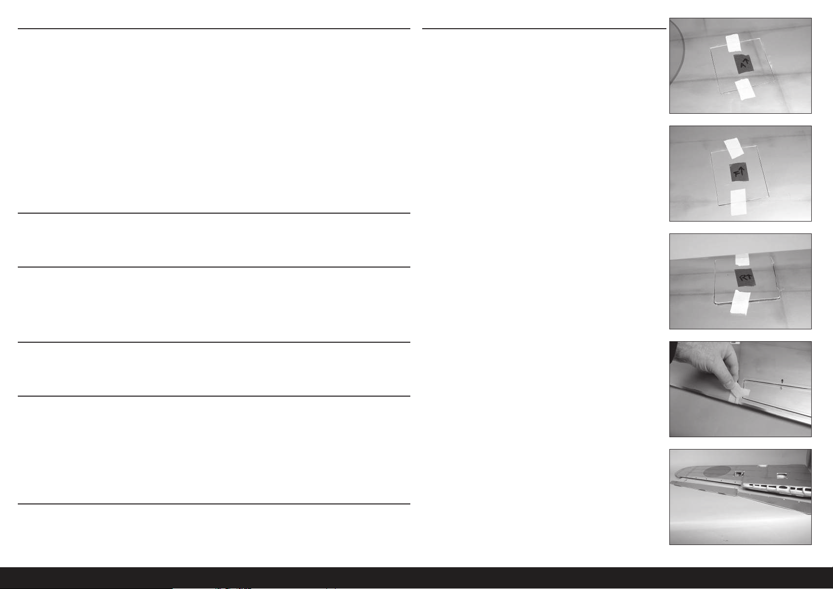
REMARQUES RELATIVES À L’ENTOILAGE IMPRIMÉ
• L’entoilage utilisé sur votre maquette a les couleurs et les marquages imprimés directement sur l’entoilage.
• L’entoilage a un endos autocollant, et il n’est pas recommandé d’utiliser de la chaleur car cela peut endommager
l’entoilage.
• Utilisez uniquement des produits de nettoyage doux sur la surface du fi lm. L’alcool dénaturé est le produit le plus
agressif que vous pouvez utiliser, mais nous vous conseillons de procéder d’abord à un essai sur une partie de
surface non visible. Une utilisation fréquente endommagera la peinture présente sur le fi lm.
• Utilisez du ruban adhésif avec précautions. Tout autre adhésif que de l’adhésif de masquage endommagera la
décoration, surtout au niveau des angles.
• Evitez le contact avec du carburant brut, surtout les carburants à base d’alcool contenant du nitrométhane.
• Essuyez les résidus de carburant immédiatement après le vol afi n d’éviter d’endommager la fi nition.
In condizioni di utilizzo normali, sono due le parti dell’aeromodello soggette a usura. La prima è la giuntura tra la
cappottatura e il portello della fusoliera, l’altra è il punto di inserimento delle ali nella fusoliera. Applicando del nastro
trasparente sull’ala nel punto di inserimento nella fusoliera e sul portello al di sotto della cappottatura è possibile
ridurre l’usura in queste zone del rivestimento. Inoltre, carteggiare l’interno della cappottatura aiuta a prevenire l’usura
di questa parte di rivestimento.
PRÉCAUTIONS DE CONSTRUCTION
Préparez la surface de travail avant le début de la construction. La surface devrait être douce et sans aucun objet
pointu. Nous recommandons de poser les pièces du fuselage sur une serviette douce ou du pit mat pour empêcher les
érafl ures ou les bosses sur la surface de l’appareil.
TRANSPORT ET STOCKAGE
Lorsque vous transportez et stockez votre maquette, vous devez avoir au minimum un espace de 2.1m de longueur et
50cm de hauteur pour la taille du fuselage. Nous vous conseillons d’utiliser des sacs d’ailes et de stabilisateurs pour
protéger ces surfaces lors du transport et du stockage. Les renvois de commande et tringleries peuvent également
endommager les autres surfaces même s’ils sont rangés dans des sacs de stockage. Transportez et stockez toujours
les ailes et le stabilisateur afi n que les tringleries ne touchent pas les autres panneaux, pour empêcher les dommages.
INSTALLATION DU SYSTÈME DE RENTRÉE
1. Utilisez un ruban adhésif à faible adhérence pour marquer les
caches de l’aileron, du volet et du système de rentrée de manière à
pouvoir les remettre sur l’aile dans le bon sens. Utilisez une fl èche
orientée vers le bord d’attaque comme guide.
VÉRIFICATION DES ÉCROUS BORGNES
Lors du montage de l’appareil, vous devrez visser les vis mécaniques dans les écrous borgnes. Nous recommandons
de prévisser les vis pour vous assurer que les écrous borgnes ne présentent pas de débris. Si les vis ne s’insèrent pas
facilement, dégagez les fi letages en utilisant le taraud et la poignée de taraud appropriés.
POIDS DU NEZ
Ce modèle nécessite probablement l’ajout d’un poids du nez à des fi ns d’équilibre. Des tests ont été réalisés sur toutes
les options de puissance. Utiliser un moteur plus lourd aide à réduire la quantité de poids requise. Assurez-vous de
bien gérer l’accélération en vol avec ces options plus larges et plus puissantes. Notre appareil test avec le moteur
recommandé Evolution
L’utilisation de moteurs autres que ceux recommandés peut nécessiter un ajout de poids à des fi ns d’équilibre. Cela
peut varier d’un avion à l’autre. Ajoutez ce poids aussi loin que possible dans le fuselage pour réduire la quantité
requise pour équilibrer. Ce poids doit être fi xé afi n de ne pas se desserrer en vol, faute de quoi la maquette ne sera pas
sécuritaire, pouvant provoquer la perte de l’appareil.
®
62cc et silencieux, et batteries de récepteur et d’allumage sous le réservoir de carburant.
POUR LES PERSONNES AYANT UNE DÉFICIENCE VISUELLE
Vous trouverez une copie de ce manuel à l’adresse www.horizonhobby.com sous l’onglet correspondant à ce modèle
particulier. N’hésitez pas à télécharger ce manuel et à utiliser un lecteur de fi chiers PDF pour agrandir un texte ou une
image correspondant lors du montage à partir du modèle imprimé.
2. Retirez le ruban qui fi xe l’aileron et le volet à l’aile.
3. Séparez l’aileron et le volet de l’aile. Mettez-les de côté dans un
endroit sûr.
76FR
Page 77
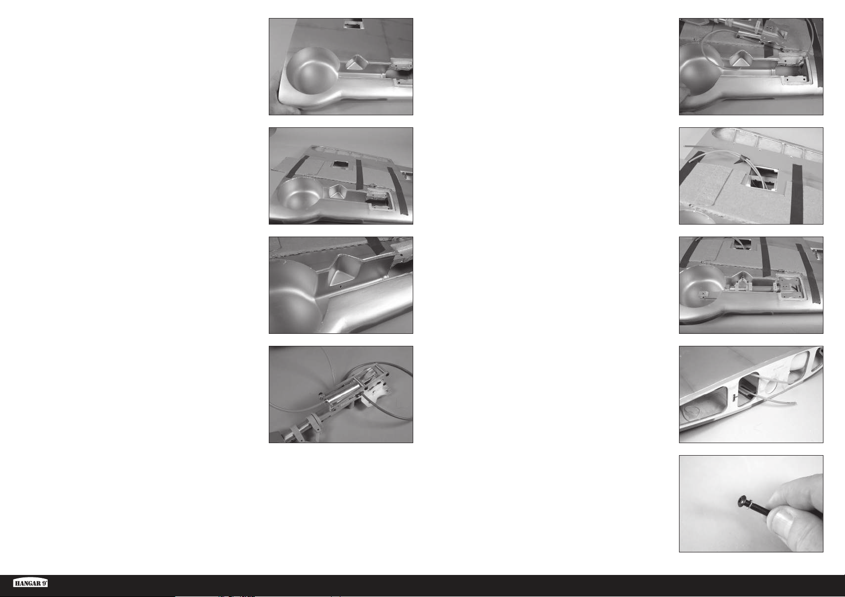
4. Utilisez un couteau et une lame n°11 pour retirer l’entoilage des
ouvertures du système de rentrée dans l’aile. Taillez l’entoilage à
l’intérieur de l’ouverture.
8. Acheminez les conduites d’air dans l’aile.
5. Utilisez un ruban adhésif à faible adhérence pour fi xer un morceau
de carton sur l’aile. Cela crée un endroit où poser le système de
rentrée lors de l’acheminement des conduites d’air et permet de ne
pas endommager le côté inférieur de l’aile.
6. Utilisez un porte-foret et une mèche de 3mm (1/8po) pour faire un
trou dans le passage du système de rentrée pour la conduite d’air.
7. Coupez un morceau de 482mm (19 pouces) de conduite d’air
orange et bleue. Fixez chaque conduite d’air au système de rentrée.
L’utilisation de couleurs différentes facilite grandement la bonne
connexion des systèmes de rentrée lors de l’assemblage de la
maquette.
Utilisez un pistolet thermique réglé sur basse
température pour assouplir légèrement les conduites
d’air afin qu’elles coulissent sur les raccords.
9. Les deux conduites d’air peuvent être récupérées au niveau de
l’ouverture du servo de volet. Utilisez un morceau de ruban adhésif à
faible adhérence pour fi xer les conduites ensemble afi n qu’elles ne
retombent pas dans l’aile.
10. Insérez le système de rentrée dans l’aile. Taillez au besoin pour
laisser un dégagement.
11. Les conduites d’air peuvent maintenant être récupérées au niveau
de la base de l’aile.
Assurez-vous que les conduites d’air de même couleur sont
orientées de la même manière sur les systèmes de rentrée de
gauche et de droite afin qu’elles fonctionnent de la même façon.
Ki-43 Oscar 60cc ARF
12. Placez un écrou de blocage sur la vis d’assemblage à tête bombée
M4 x 25. À ce stade, préparez quatre vis.
77 FR
Page 78
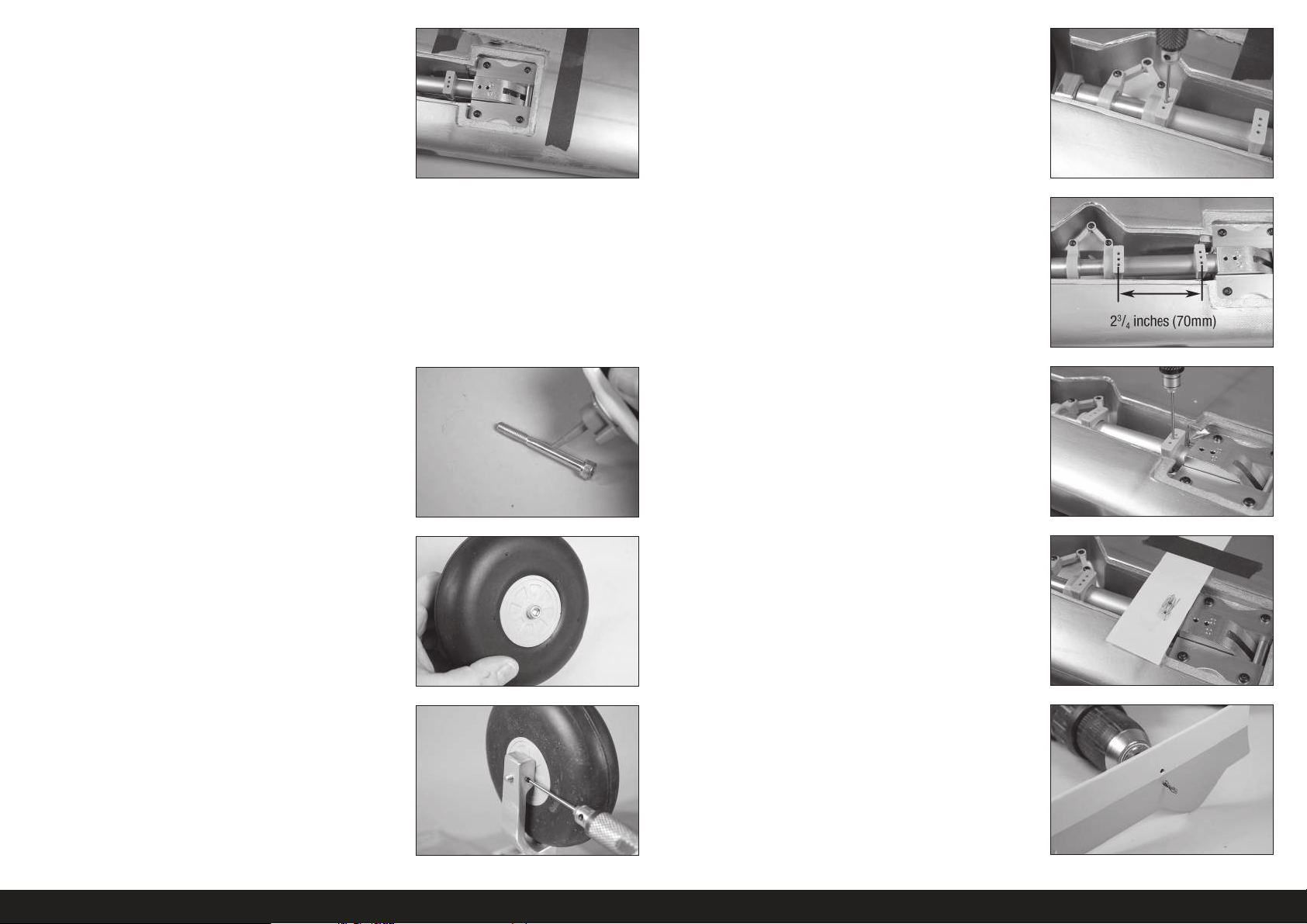
13. Utilisez les vis d’assemblage à tête bombée M4 x 25 pour fi xer le
système de rentrée dans l’aile. Appliquez une goutte de frein-fi let
sur chaque vis avant l’installation. Serrez les vis à l’aide d’une clé à
six pans de 2,5mm.
17. Positionnez le support de trappe de train près de la roue aussi près
de celle-ci que possible. La zone plane doit être alignée avec le bas
de l’aile. Utilisez une vis de fi xationM3 x 5 et une clé à six pans de
1,5mm pour fi xer le support de trappe de train en position.
Le carton peut être retiré de l’aile une fois
le système de rentrée bien fixé.
Il peut être nécessaire d’utiliser des entretoises sous le châssis de
rentrée pour vous assurer qu’il n’y a pas de contrainte de torsion
lorsqu’il est serré à son emplacement. La contrainte de torsion peut
entraîner un fonctionnement intermittent du système de rentrée.
14. Placez une goutte d’huile de machine légère sur la vis d’assemblage
creuse M6 x 55 qui fera offi ce d’essieu de roue.
15. Faites glisser la vis d’assemblage creuse M6 x 55 à travers la roue.
Veillez à ce que la roue tourne librement sur la vis.
Ne serrez pas trop les vis et n’utilisez pas de frein-filet, car
cela endommagera le matériau composite des supports.
18. Positionnez le support supérieur à 70mm (23/4 pouces) du support
inférieur.
19. Utilisez une vis de fi xationM3 x 5 et une clé à six pans de 1,5mm
pour fi xer le support de trappe de train en position.
Ne serrez pas trop les vis et n’utilisez pas de frein-filet, car
cela endommagera le matériau composite des supports.
20. Collez un morceau de papier sur l’aile qui se mettra par-dessus
le support supérieur. Frottez un crayon de bois sur le papier pour
révéler l’emplacement des orifi ces de montage.
16. Vissez la vis dans le système de rentrée. Serrez la vis suffi samment
pour que la roue puisse tourner librement, mais sans qu’il n’y ait de
mouvement excessif de la roue sur la vis. Une fois en place, utilisez
une vis de fi xation M3 x 5 que vous serrerez avec une clé à six pans
de 2mm. Utilisez une goutte de frein-fi let sur la vis d’assemblage
creuse M6 x 55 et sur la vis de fi xation M3 x 5 pour les empêcher de
se desserrer sous les vibrations.
21. Utilisez une perceuse et une mèche de 3mm (1/8po) pour percer
les trous pour le montage du train inférieur dans la trappe de train.
78FR
Page 79
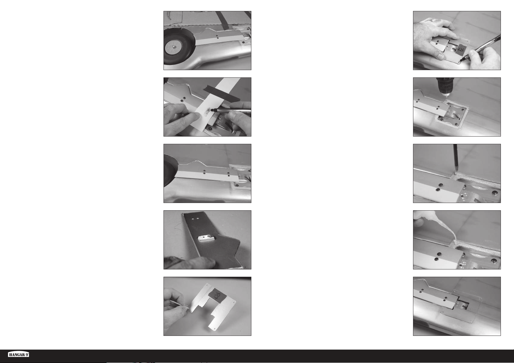
22. Fixez la trappe du train au support à l’aide de deux vis à tête
bombée M3 x 12 et d’une clé à six pans de 2mm.
Vérifiez le positionnement de la trappe afin de
vous assurer qu’elle est centrée dans l’ouverture
et alignée avec l’ouverture près de la roue.
Ne serrez pas trop les vis et n’utilisez pas de frein-filet, car
cela endommagera le matériau composite des supports.
27. Positionnez le cache. Utilisez un stylo-feutre pour marquer
l’emplacement des vis de montage
23. Utilisez un stylo-feutre pour marquer l’emplacement des vis de
montage de la trappe de train supérieure sur la trappe du train.
24. Retirez le couvercle et utilisez une perceuse et une mèche de 3mm
(1/8po) pour percer les deux trous pour les vis de montage de la
trappe de train supérieure. Vous pouvez maintenant fi xer la trappe
aux supports à l’aide des quatre vis à tête bombée M3 x 12 et d’une
clé à six pans de 2mm.
25. Si la trappe du train n’est pas alignée avec le bas de l’aile, il peut
être nécessaire d’ajuster les supports. La zone de montage du
support inférieur peut également être poncée à l’aide d’un papier
abrasif à grain moyen afi n d’ajuster l’alignement de la trappe du
train.
28. Utilisez un porte-foret et une mèche de 1,5mm (1/16po) pour
percer les supports de montage pour les caches de systèmes de
rentrée.
29. Vissez une vis à tôleM2 x 10 dans chaque trou à l’aide d’un
tournevis cruciforme n°1. Retirez les vis avant de continuer.
30. Appliquez une petite quantité de CA fi ne pour durcir les trous
réalisés à l’étape précédente. Laissez la CA sécher complètement
avant d’installer le cache du système de rentrée.
26. Utilisez un couteau ou un autre outil tranchant pour perforer
l’entoilage au niveau des trous de vis qui fi xeront le cache sur
l’aile. Retirez également l’entoilage pour dégager le mécanisme de
rentrée.
Ki-43 Oscar 60cc ARF
31. Fixez le cache du système de rentrée à l’aile à l’aide de quatre vis
à tôleM2 x 10. Utilisez un tournevis cruciforme n° 1 pour serrer les
vis.
79 FR
Page 80
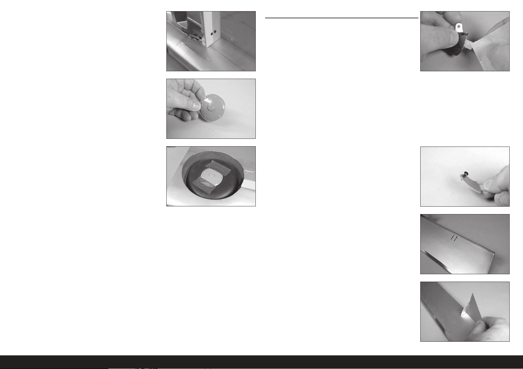
32. Assurez-vous que le système de rentrée puisse se déployer
entièrement sans que la trappe du train ne touche le cache. Taillez la
trappe du train au besoin si elle touche le cache.
Il y aura du mouvement dans le train pendant le fonctionnement,
donc assurez-vous qu’il y ait un écart entre la trappe du train
et l’aile de manière à ce que ces deux éléments n’entrent
pas en contact pendant le fonctionnement du train.
33. Utilisez des ciseaux et un papier abrasif à grain moyen pour préparer
les cache-moyeux à l’installation.
Vous pouvez peindre les cache-moyeux si vous le souhaitez.
Assurez-vous de poncer et préparer entièrement la surface. La
peinture s’écaillera si elle est appliquée directement sur le cachemoyeu sans préparation. Testez toujours la peinture sur une
pièce de rebut pour vérifier sa compatibilité avec le plastique.
INSTALLATION DE L’AILERON
1. Utilisez un papier abrasif à grain moyen pour poncer légèrement
le renvoi de commande là où il s’ajuste dans la surface de
commande. Nettoyez la zone poncée à l’aide de papier absorbant
imprégné d’alcool isopropylique pour enlever toute trace d’huile ou
d’impuretés. Cela permet d’obtenir la texture de surface nécessaire
pour l’adhérence de la colle époxy.
Utilisez du ruban adhésif sur la zone peinte afin de ne pas
retirer la partie exposée du renvoi de commande. Retirez
le ruban une fois le renvoi de commande poncé.
34. Utilisez un adhésif de contact pour coller le cache-moyeu à la
roue. Utilisez du ruban adhésif à faible adhérence pour maintenir le
cache-moyeu en place jusqu’au séchage complet de la colle.
Répétez cette partie pour l’installation du
système de rentrée restant.
2. Insérez la vis à tête bombée M3 x 10 dans le trou du renvoi de
commande. Pour que la vis se positionne facilement dans le trou,
retirez toute peinture à l’aide d’un couteau et d’une lame nº11.
Vérifi ez tous les renvois de commande.
Le trou doit être assez large pour que la vis puisse glisser à travers,
mais la vis doit être ajustée dans le trou et ne pas trop bouger.
3. Parcourez le bas de l’aileron avec votre doigt pour trouver
l’emplacement du renvoi de commande. Utilisez un couteau et une
lame n°11 pour retirer l’entoilage et exposer les fentes du renvoi de
commande.
4. Testez l’ajustement du renvoi de commande dans la fente. Ne forcez
pas le renvoi de commande dans la fente. Utilisez une équerre pour
vous assurer que le renvoi de commande est d’équerre par rapport
à la surface de commande. Ne forcez pas le renvoi de commande
dans la fente.
80FR
Page 81
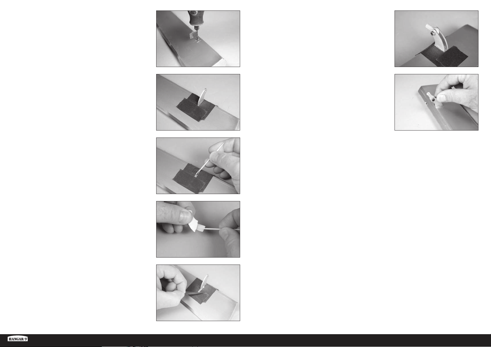
Si le renvoi de commande est trop juste, ou n’est pas d’équerre,
utilisez un outil rotatif avec une mèche de 2,5mm (3/32po)
pour doucement élargir et reformer le trou. Enroulez un morceau
de ruban adhésif à faible adhérence autour de la mèche pour
marquer la profondeur de la mèche afin qu’elle ne traverse pas
accidentellement le côté opposé de la surface de commande.
9. Testez l’ajustement du renvoi de commande restant. Lorsque vous
collez le renvoi de commande, placez l’extrémité à bille entre les
renvois et insérez la vis à tête bombée M3 x 10 à travers les renvois
de commande et les embouts de bielle. Cela permet d’aligner
correctement les renvois, facilitant ainsi l’installation de la tringlerie.
5. Mettez du ruban autour de la fente dans l’aileron pour le renvoi de
commande de l’aileron.
6. Retirez les renvois de commande des surfaces de commande.
Appliquez la colle époxy dans la fente de l’aileron. Assurez-vous
que la colle époxy rentre bien dans la fente pour garantir une bonne
fi xation entre les surfaces et le renvoi de commande.
7. Appliquez de la colle époxy sur la partie du renvoi de commande qui
rentre dans la fente. Utilisez suffi samment de colle époxy afi n que
le renvoi de commande soit entièrement rattaché aux surfaces de
commande.
10. Une fois la colle époxy entièrement séchée, tirez sur le renvoi
de commande pour vous assurer qu’il est fermement collé dans
l’aileron. Si ce n’est pas le cas, retirez le renvoi de commande et
poncez toute trace de colle. Répétez cette partie pour coller le renvoi
de commande dans l’aileron.
8. Avant le durcissement total de la colle époxy, retirez le ruban
adhésif autour du renvoi de commande. Ainsi, la colle époxy peut
s’écouler autour du renvoi de commande et créer un petit joint entre
le renvoi de commande et la surface. Le rendu est plus net et la
fi xation plus solide. Avant de continuer, laissez la colle époxy sécher
complètement.
Ki-43 Oscar 60cc ARF
81 FR
Page 82
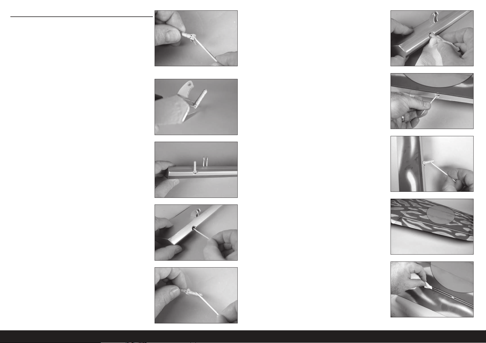
MISE EN PLACE DES CHARNIÈRES DES AILERONS
Ne mélangez pas la colle époxy avant d’en recevoir l’instruction.
Utilisez les charnières courtes pour les ailerons. Les
charnières longues sont utilisées pour les volets en
raison de la technique de mise en place utilisée.
1. Appliquez une petite quantité d’huile sur le point de fl exion de la
charnière pour prévenir toute pénétration de colle époxy dans la
charnière.
2. Insérez la charnière, de sorte que le centre du point de la charnière
soit aligné à l’extrémité avant du biseau sur la surface de
commande. Assurez-vous que la charnière peut bouger librement.
3. Positionnez la charnière, de sorte qu’elle soit perpendiculaire à la
ligne de la charnière en position entièrement déviée.
6. Insérez les charnières dans la surface de commande. Vérifi ez que les
charnières sont à la bonne position. Imprégnez du papier absorbant
d’alcool isopropylique et retirez tout excédent de colle époxy. Avant
de continuer, laissez la colle époxy sécher complètement.
7. Préparez un mélange de 15mL (1/2once) de colle époxy
«30minutes». Utilisez un cure-dent pour appliquer la colle époxy à
l’intérieur de chaque trou pour les charnières.
8. Appliquez la colle époxy à l’extérieur de la charnière à l’aide d’un
cure-dent.
4. Préparez un mélange de 15mL (1/2once) de colle époxy
«30minutes». Retirez les charnières, puis utilisez un cure-dent
pour appliquer la colle époxy à l’intérieur de chaque trou pour les
charnières.
5. Appliquez la colle époxy à l’extérieur de la charnière à l’aide d’un
cure-dent.
9. Insérez l’aileron sur l’aile. Vérifi ez que l’aileron peut bouger
librement et que les charnières sont toutes correctement alignées.
10. Imprégnez du papier absorbant d’alcool isopropylique et retirez tout
excédent de colle époxy. Utilisez du ruban adhésif à faible adhérence
pour maintenir l’aileron en place jusqu’au séchage complet de la
colle époxy.
82FR
Page 83
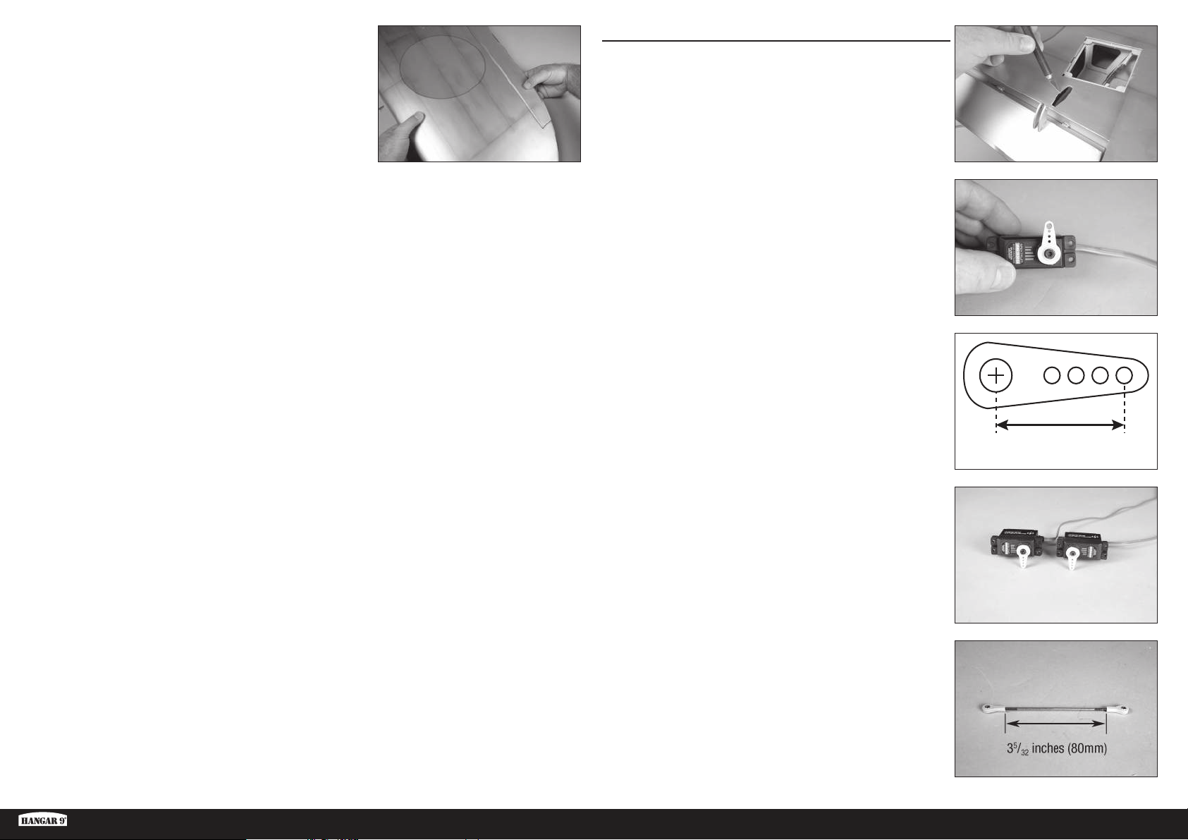
11. Une fois la colle époxy entièrement séchée, tirez sur l’aile et l’aileron
pour vous assurer que les charnières sont fermement collées. Si
ce n’est pas le cas, retirez l’aileron et poncez toute trace de colle.
Répétez cette partie pour coller les charnières.
INSTALLATION DU SERVO DE L’AILERON
1. Utilisez un couteau et une lame n°11 pour retirer l’entoilage pour la
sortie de la barre de liaison de l’aileron.
2. Centrez le servo de l’aileron. Fixez le renvoi de servo sur le servo de
manière à ce qu’il soit perpendiculaire à la ligne de centre du servo.
3. Lorsque vous fi xez la tringlerie au bras du servo de l’aileron, utilisez
le trou dans le bras qui se trouve à 16mm (5/8po) du centre du
bras de servo.
5/8 inch
(16mm)
Ki-43 Oscar 60cc ARF
4. Préparez les servos d’ailerons gauche et droite à ce stade.
5. Assemblez la tringlerie de l’aileron à l’aide de deux extrémités à bille
et de la barre fi letée de 100mm (3
à bille à 12tours sur l’articulation. Ajustez la longueur de manière
à ce que la distance entre les extrémités à bille soit de 80mm
5
/32pouces).
(3
83 FR
15
/16po). Vissez chaque extrémité
Page 84
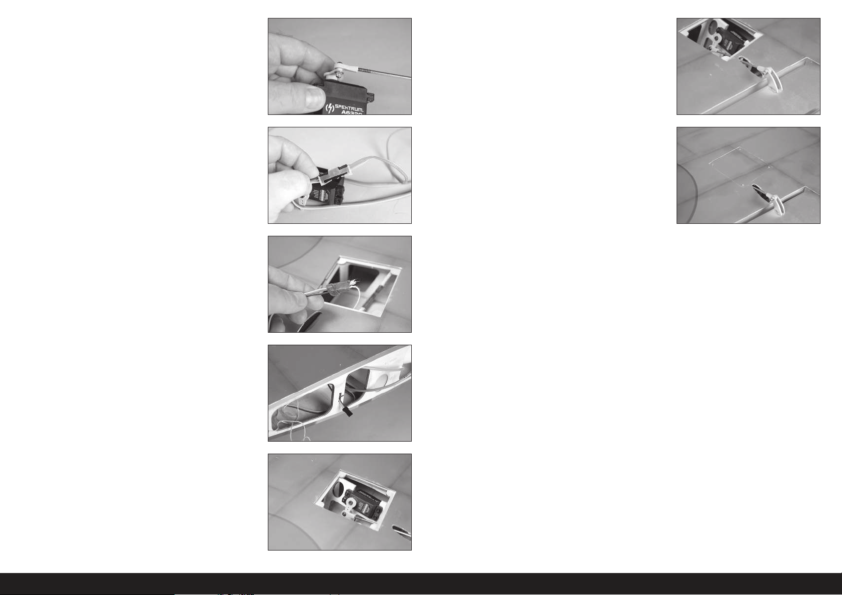
6. Fixez l’articulation à bille du servo au bras du servo à l’aide d’une vis
à tête bombée M3 x 10, d’un contre-écrouM3 et d’une rondelleM3.
Utilisez une clé à six pans de 2,5mm et un tournevis à écrou de
5,5mm pour le serrage du matériel.
11. Fixez l’articulation à bille du servo au renvoi de commande à l’aide
d’une vis à tête bombée M3 x 10, d’un contre-écrouM3 et d’une
rondelleM3. Utilisez une clé à six pans de 2,5mm et un tournevis à
écrou de 5,5mm pour le serrage du matériel.
Branchez le servo au système radio pour maintenir le
servo de l’aileron en position centrée. Déconnectez la
bille du renvoi de commande, puis ajustez la tringlerie
de sorte que l’aileron soit en position neutre. Réinstallez
la quincaillerie une fois la tringlerie ajustée.
7. Fixez une rallonge de servo de 150mm (6po) au servo à l’aide
d’une bague de retenue disponible dans le commerce (SPMA3054).
La longueur de la rallonge peut varier en fonction
du choix du servo. La rallonge répertoriée est
compatible avec les servos recommandés.
8. Nouez ou collez la fi celle située dans l’aile à l’extrémité du câble du
servo.
9. Utilisez la fi celle pour tirer le câble du servo à travers l’ouverture à la
base de l’aile.
Nous avons laissé une petite quantité de ficelle sur le câble
du servo de l’aileron afin de pouvoir facilement le différencier
avec le câble du servo du volet qui sera installé plus tard.
12. Suivez les étapes mentionnées pour le cache du système de rentrée
pour installer le cache de l’aileron.
10. Installez le servo de l’aileron dans l’aile avec la sortie dirigée vers le
bord d’attaque. Veillez à préparer les trous pour le montage du servo
en vissant une vis de montage de servo dans chaque trou et en la
retirant. Durcissez les emplacements des vis de montage avec de la
CA fi ne avant d’installer le servo.
84FR
Page 85
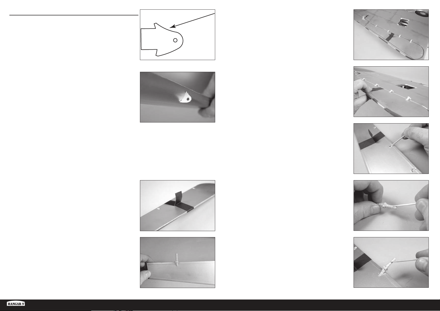
MISE EN PLACE DES CHARNIÈRES DES VOLETS
Les volets doivent être positionnés sur l’aile avant que la colle
époxy ne commence à sécher. Assurez-vous d’avoir bien lu
toutes les étapes avant de mélanger n’importe quelle colle
époxy. Ne collez qu’un volet à la fois pour vous laisser assez
de temps pour installer correctement les charnières.
1. Repérez les renvois de commande du volet. Une fois installée, la
portion concave du renvoi (comme indiqué dans le dessin) sera
orientée vers le haut des volets.
2. Parcourez le bord d’attaque du volet avec votre doigt pour trouver
l’emplacement des renvois de commande du volet. Utilisez un
couteau et une lame n°11 pour retirer l’entoilage et exposer les
fentes du renvoi de commande. Utilisez de la colle époxy 15minutes
pour fi xer les renvois de commande du volet. Retirez tout l’excédent
de colle époxy avec du papier absorbant imprégné d’alcool
isopropylique.
Suivez les étapes mentionnées pour les renvois de commande des
ailerons pour installer les renvois de commande des volets. Vérifiez
bien que les renvois de commande des volets sont fermement
collés dans les volets après séchage complet de la colle.
5. Vérifi ez l’ajustement du volet sur l’aile. Il doit être centré dans
l’ouverture. La goupille de charnière doit être positionnée
directement sur l’écart entre le bord d’attaque du volet et le bord
arrière de l’ouverture de l’aile. Testez le fonctionnement du volet
pour vous assurer que les charnières sont correctement alignées et
que le volet bouge librement.
6. Le volet doit également s’aligner avec le bas de l’aile lorsque les
charnières sont positionnées correctement.
Utilisez une colle époxy 15 minutes ou 30 minutes pour
vous laisser assez de temps pour installer la charnière.
7. Retirez le volet de l’aile et retirez les charnières. Appliquez de la
colle époxy dans chaque trou du volet.
N’utilisez pas trop de colle époxy lorsque vous collez les
charnières. Utilisez suffisamment de colle époxy pour
que les charnières adhèrent bien aux surfaces.
3. Enroulez un morceau de ruban à faible adhérence autour du volet
pour créer une languette de manière à pouvoir lever et abaisser le
volet pendant la mise en place des charnières.
Utilisez les charnières longues pour installer les volets sur l’aile.
4. Testez l’ajustement des charnières sur le volet. N’utilisez pas de
colles maintenant. Glissez la charnière en place. Positionnez-la
comme indiqué, en vous assurant qu’elle peut bouger librement.
Ki-43 Oscar 60cc ARF
8. Appliquez de la colle époxy sur chaque charnière qui s’insérera dans
le volet. Insérez les charnières dans le volet.
9. Appliquez de la colle époxy sur chaque charnière qui s’insérera dans
l’aile.
85 FR
Page 86
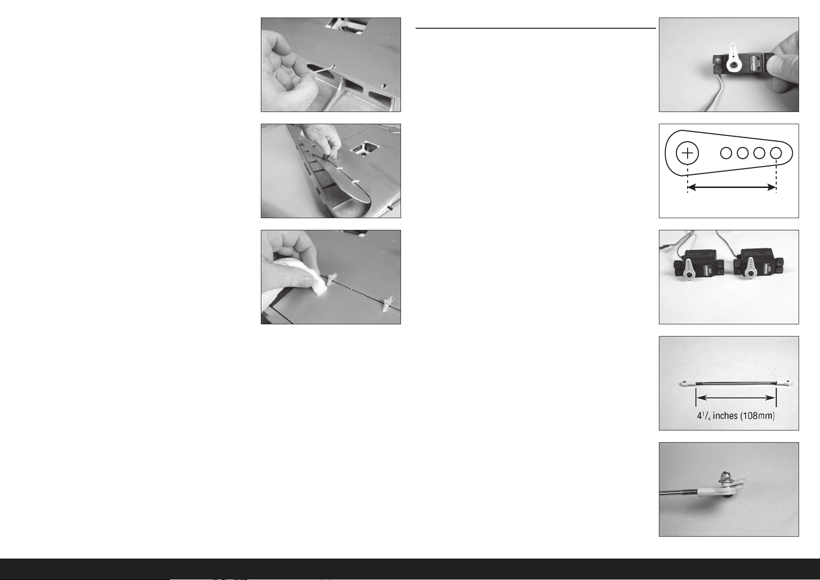
10. Appliquez de la colle époxy dans chaque trou de l’aile.
INSTALLATION DU SERVO DU VOLET
1. Centrez le servo du volet. Fixez le renvoi de servo sur le servo de
manière à ce qu’il soit perpendiculaire à la ligne de centre du servo.
Nous conseillons de régler les coudes sur 0% pour les radios qui
utilisent un commutateur 3 positions afin d’éviter d’endommager
le servo si la tringlerie n’est pas à la bonne longueur.
11. Insérez le volet sur l’aile. Vérifi ez que le volet peut bouger librement
et que les charnières sont toutes correctement alignées. Utilisez du
ruban adhésif à faible adhérence pour maintenir le volet jusqu’au
séchage complet de la colle époxy.
12. Imprégnez du papier absorbant d’alcool isopropylique et retirez
tout excédent de colle époxy avant qu’elle ne sèche. Faites
attention à ne pas mettre de colle époxy dans la partie mobile de la
charnière ou entre le volet et l’aile. Continuez une fois la colle époxy
complètement sèche pour les deux jeux de charnières de volets.
Vérifiez bien que les charnières des volets sont fermement
collées après séchage complet de la colle.
Répétez cette partie pour l’installation des
charnières de volet restantes.
2. Lorsque vous fi xez la tringlerie au bras du servo de l’aileron, utilisez
le trou dans le bras qui se trouve à 16mm (5/8po) du centre du
bras de servo.
3. Préparez les servos de volets gauche et droite à ce stade.
4. Assemblez la tringlerie du volet à l’aide de deux extrémités à bille
et de la barre fi letée de 120mm (4
à bille à 12tours sur l’articulation. Ajustez la longueur de manière
à ce que la distance entre les extrémités à bille soit de 108mm
1
/4pouces).
(4
23
/32po). Vissez chaque extrémité
5/8 inch
(16mm)
5. Retirez le bras de servo du servo. Fixez l’articulation à bille du servo
au bras du servo à l’aide d’une vis à tête bombée M3 x 10, d’un
contre-écrouM3 et d’une rondelleM3. Utilisez une clé à six pans
de 2,5mm et un tournevis à écrou de 5,5mm pour le serrage du
matériel.
86FR
Page 87
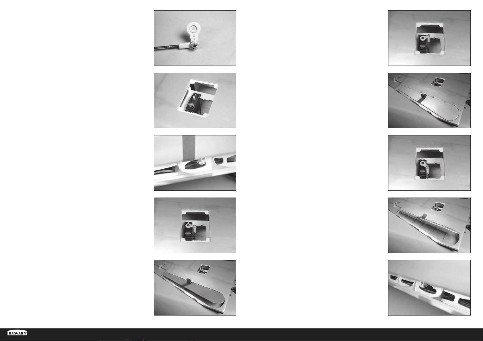
6. L’articulation à bille doit être fi xée sur le côté inférieur du bras de
servo comme indiqué.
7. Installez le servo du volet dans l’aile avec la sortie dirigée vers le
bord d’attaque. Veillez à préparer les trous pour le montage du servo
en vissant une vis de montage de servo dans chaque trou et en la
retirant. Durcissez les emplacements des vis de montage avec de la
CA fi ne avant d’installer le servo.
Les servos de volets peuvent être positionnés dans
l’aile pour permettre l’utilisation d’un harnais en
Y pour connecter les servos au récepteur.
11. Mettez le servo en position volet relevé à l’aide du système radio.
Réglez les coudes au niveau du système radio pour aligner le volet
avec le bas de l’aile.
8. Fixez l’articulation à bille du servo au renvoi de commande à l’aide
d’une vis à tête bombée M3 x 10, d’un contre-écrouM3 et d’une
rondelleM3. Utilisez une clé à six pans de 2,5mm et un tournevis à
écrou de 5,5mm pour le serrage du matériel.
9. Fixez le bras de servo sur le servo.
10. Ajustez la longueur de la tringlerie pour positionner le volet en
position intermédiaire de 25–30
N’oubliez pas de régler les coudes sur 0% pour
les positions haute et basse afin de prévenir tout
dommage au servo, au volet ou à la tringlerie.
mm.
12. Mettez le servo en position volet complètement sorti de 50–60
à l’aide du système radio. Ajustez les coudes dans le système radio
pour obtenir les mesures indiquées.
13. La tringlerie peut frotter contre la structure de l’aile en fonction du
servo choisi. Utilisez un couteau et une lame nº 11 ou un outil rotatif
et un rouleau à poncer pour limer la structure de l’aile au besoin
pour dégager la tringlerie.
mm
Ki-43 Oscar 60cc ARF
87 FR
Page 88
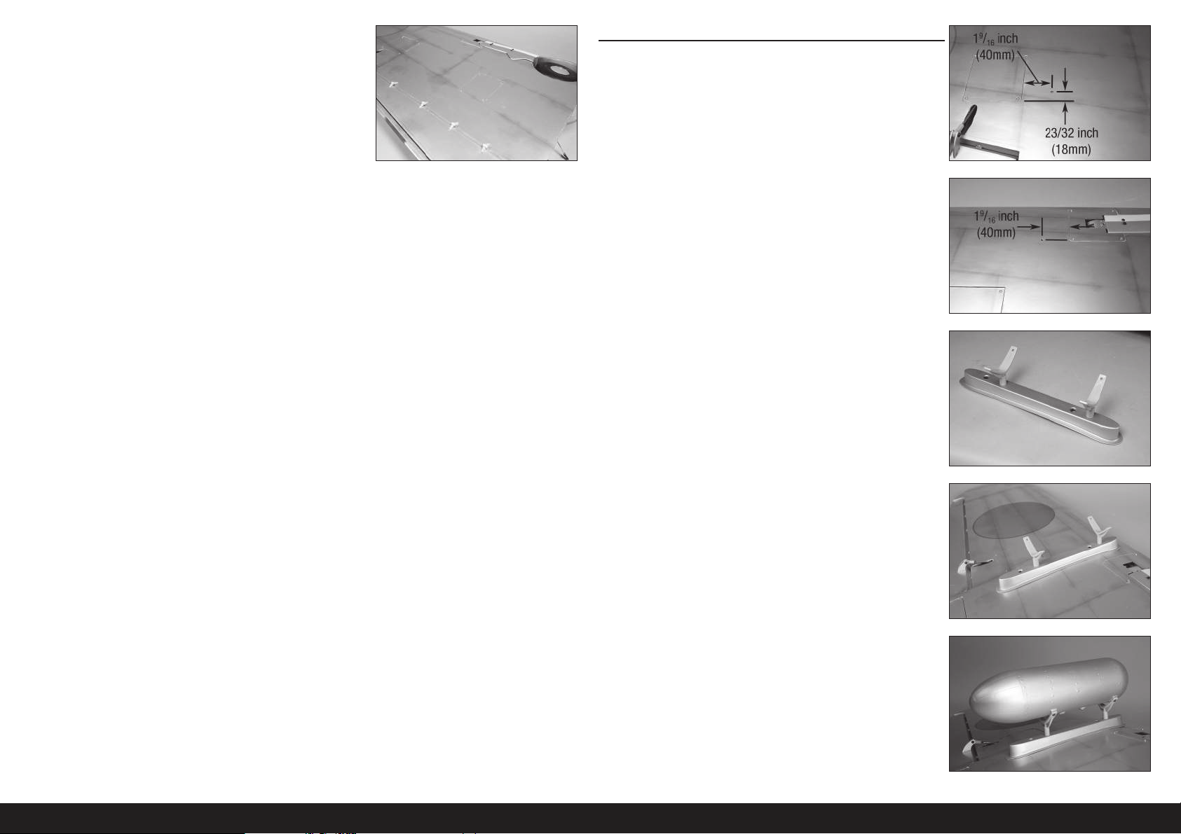
14. Suivez les étapes mentionnées pour le cache du système de rentrée
pour installer le cache du volet.
Répétez cette partie pour l’installation des servos de volet restants.
INSTALLATION DU RÉSERVOIR LARGABLE
1. Parcourez le bas de l’aile avec votre doigt pour trouver les écrous
borgnes du support du réservoir largable. Utilisez un couteau et une
lame n°11 pour retirer l’entoilage afi n de révéler les écrous borgnes.
Vissez d’abord manuellement une vis dans les écrous
borgnes afin de vous assurer que les filets sont dégagés.
Fausser ou arracher le filetage, ou endommager les écrous
borgnes dans l’aile, sont des conditions qui ne pourront
être rectifiées qu’au prix d’un effort considérable.
2. Vissez les supports du réservoir largable dans les écrous borgnes
dans les pylônes. Ne serrez pas trop les supports pour ne pas
endommager le pylône.
3. Fixez le pylône à l’aile à l’aide de deux vis d’assemblage creuses M4
x 15 et de deux écrous de blocageM4. Utilisez une clé à six pans de
3mm pour serrer les vis.
Appliquez une goutte de colle pour verrière sur chaque vis
avant leur installation. Cela empêchera les vis de se desserrer
à cause des vibrations, tout en étant facilement retirables.
4. Fixez le réservoir largable aux supports à l’aide de quatre vis à tête
bombéeM3x12. Utilisez une clé à six pans de 2mm pour serrer
les vis.
Appliquez une goutte de colle pour verrière sur chaque vis
avant leur installation. Cela empêchera les vis de se desserrer
à cause des vibrations, tout en étant facilement retirables.
Répétez cette partie pour l’installation du
88FR
réservoir largable restant.
Page 89
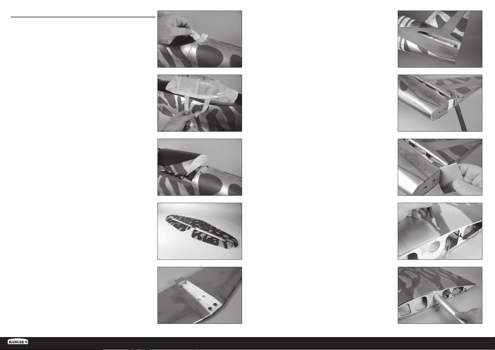
INSTALLATION DU STABILISATEUR
1. Retirez le ruban et les matériaux d’emballage du fuselage.
5. Parcourez les côtés du fuselage avec votre doigt pour trouver
l’ouverture pour le stabilisateur. Utilisez un couteau et une lame
n°11 pour retirer l’entoilage du fuselage.
6. Utilisez une scie rasoir pour retirer la partie de la colonne de
l’empennage de la fente du stabilisateur.
La colonne de l’empennage est laissée en position
d’usine pour prévenir tout dommage et maintenir
l’intégrité structurelle du fuselage pendant l’expédition.
Vous devez la retirer pour installer le stabilisateur.
2. Déplacez le loquet de la verrière vers l’avant du fuselage. Levez la
trappe de la verrière du fuselage à l’arrière et retirez-la du fuselage.
Mettez-la de côté dans un endroit sûr.
3. Séparez les élévateurs du stabilisateur. 8. Parcourez le haut de l’aile avec votre doigt pour trouver l’écrou
4. Parcourez le bas du stabilisateur avec votre doigt pour trouver le
centre. Utilisez un couteau et une lame n°11 pour retirer l’entoilage
de la partie centrale.
7. Utilisez du papier abrasif à grain moyen pour poncer le fuselage afi n
que le raccord avec la fente du stabilisateur soit bien lisse.
borgne du boulon de maintien de l’aile. Utilisez un couteau avec
une lame n°11 pour retirer l’entoilage de l’aile pour exposer l’écrou
borgne du boulon de maintien de l’aile.
Pour plus de sécurité, vous pouvez poser de la colle sur
l’écrou borgne à l’intérieur de l’aile. Une colle époxy épaissie
aux microballons conviendra bien. Faites attention de ne pas
laisser pénétrer de colle dans les filets de l’écrou borgne.
9. Glissez le tube d’aile dans la cavité dédiée.
Il peut être difficile de glisser le tube d’aile dans la cavité.
Polir le tube d’aile avec un papier abrasif à grains fins
ou de la paille de fer peut faciliter l’installation du tube
d’aile. Ne forcez pas le tube d’aile dans la douille, car cela
peut endommager la structure à l’intérieur de l’aile.
Ki-43 Oscar 60cc ARF
89 FR
Page 90
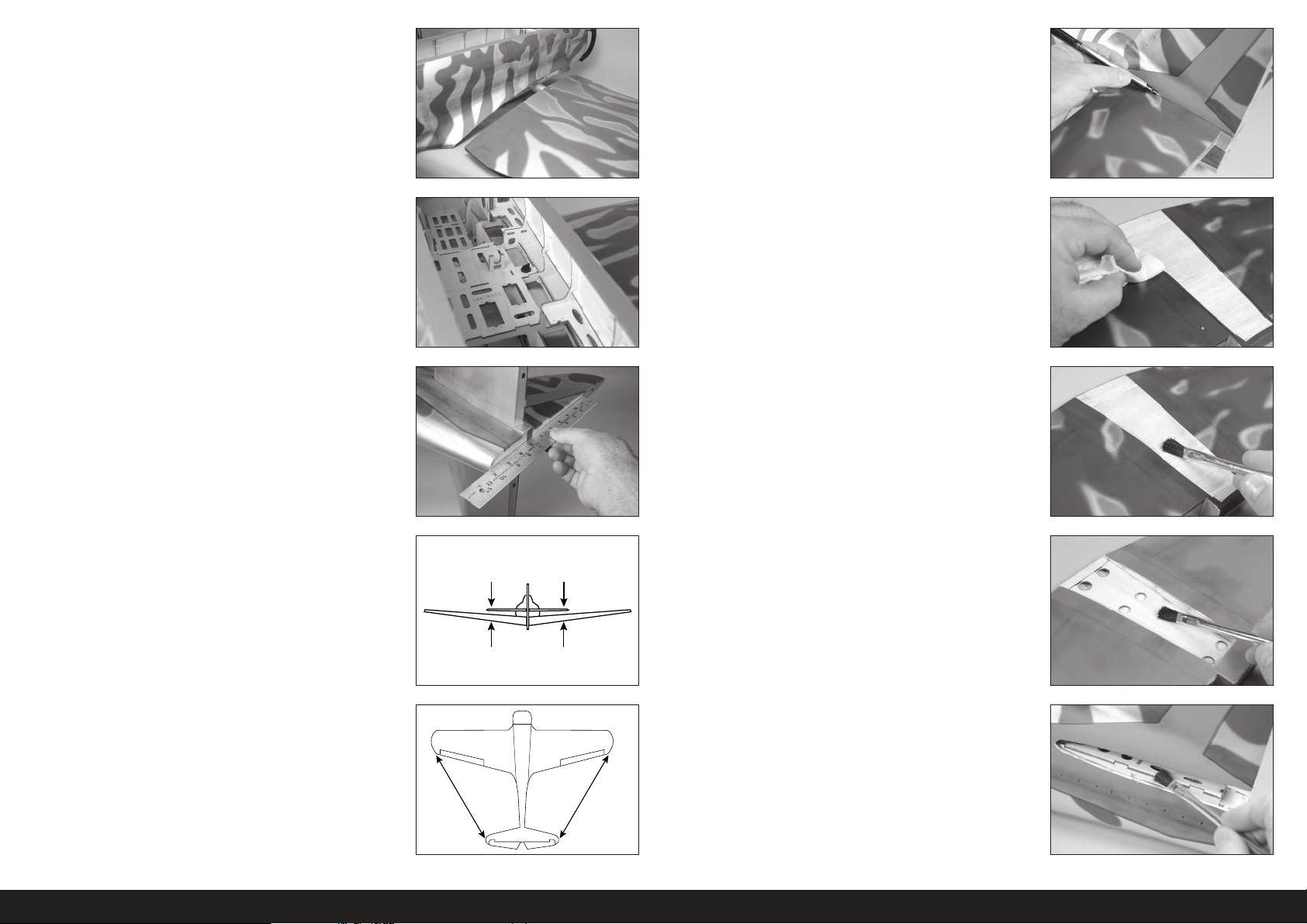
10. Remettez le panneau d’aile dans sa position. Guidez les fi ls de volets
et d’ailerons, ainsi que les conduites d’air du système de rentrée,
dans le fuselage.
15. Utilisez un stylo-feutre pour transférer le contour du fuselage sur le
haut du stabilisateur.
11. Fixez l’aile au fuselage à l’aide de la vis papillon en nylon 1/4-20 x
1.
Répétez les étapes pour fixer le panneau
d’aile restant sur le fuselage.
12. Mettez le stabilisateur en place. Utilisez une règle pour aligner
l’arrière du stabilisateur et la dérive.
13. Reculez de 2 ou 3mètres (8-10pieds) et vérifi ez que le stabilisateur
est aligné avec l’aile. Poncez légèrement le pontet du stabilisateur
sur le fuselage pour corriger tout problème d’alignement.
A=A
16. Munissez-vous d’une règle et d’un couteau avec une lame n°11
pour couper soigneusement l’entoilage de 3mm (1/8po) à l’intérieur
de la ligne tracée sur le haut du stabilisateur pour retirer l’entoilage
du centre du stabilisateur. Faites attention à ne pas découper la
structure en bois, car cela fragiliserait le stabilisateur.
17. Préparez un mélange de 25ml (3/4once) de colle époxy 30minutes.
Utilisez une brosse spéciale pour appliquer la colle époxy sur la
surface de bois exposée en haut du stabilisateur.
18. Utilisez une brosse spéciale pour appliquer la colle époxy sur la
surface de bois exposée en bas du stabilisateur également.
14. Mesurez du bout de chaque aile au bout de chaque stabilisateur.
Ajustez le stabilisateur de façon à ce que les mesures soient
identiques pour les deux côtés.
AA
19. Utilisez une brosse spéciale pour appliquer la colle époxy sur la
surface de montage du stabilisateur pour le stabilisateur. Remettez
le stabilisateur sur le fuselage et vérifi ez son alignement. Imprégnez
du papier absorbant d’un peu d’alcool isopropylique et retirez
tout excédent de colle époxy du fuselage et du stabilisateur avant
AA
A=A
qu’elle ne sèche. Avant de continuer, laissez la colle époxy sécher
complètement.
Vérifiez de façon répétée la position du stabilisateur pendant
le séchage pour vous assurer qu’il n’a pas bougé.
90FR
Page 91
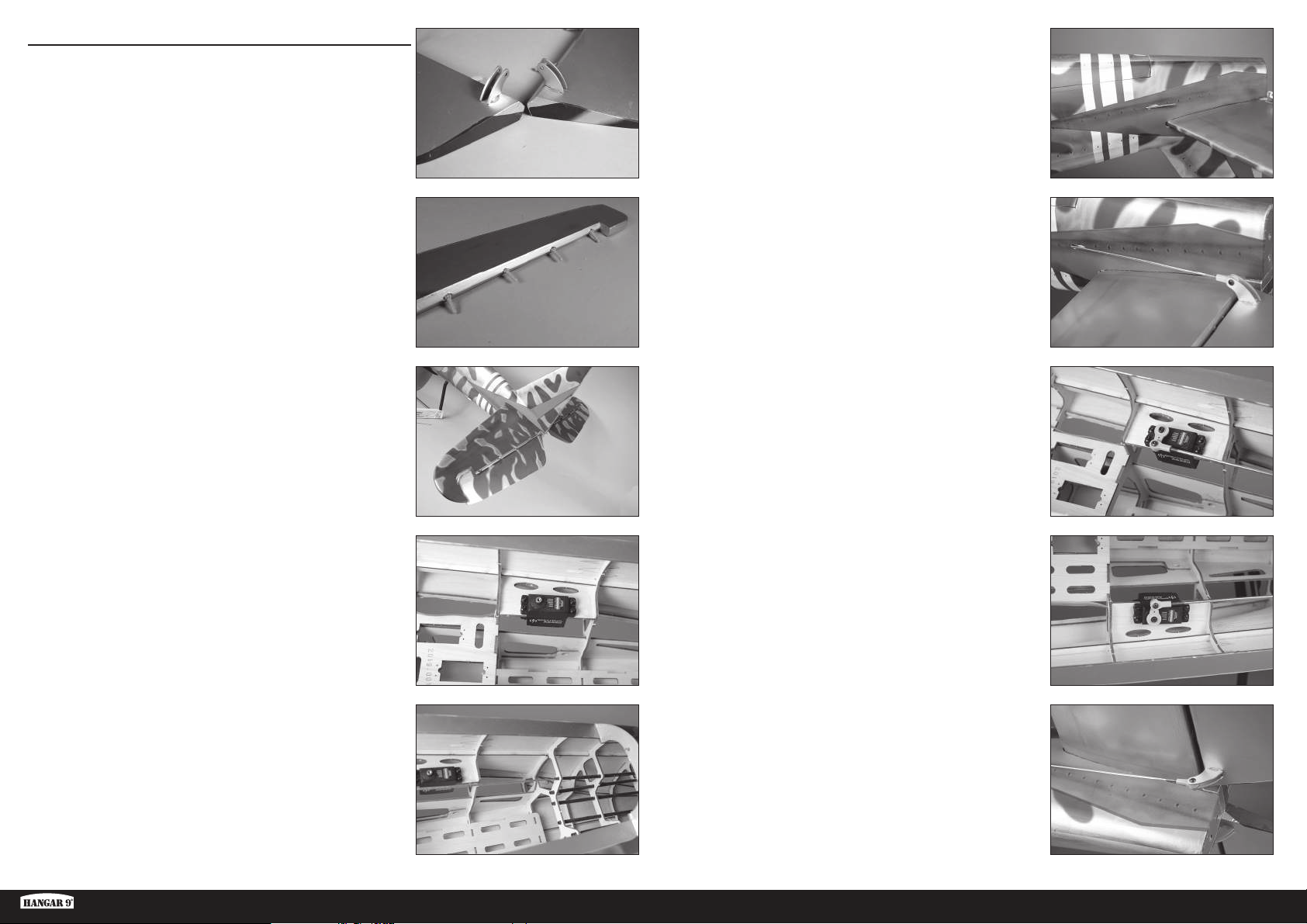
INSTALLATION DES ÉLÉVATEURS
1. Installez les renvois de commande des élévateurs. Leur installation
est identique à celle des renvois de commande de l’aileron.
Vérifiez que les renvois de commande sont
fermement collés avant de continuer.
6. Utilisez un couteau et une lame n°11 pour tailler l’entoilage de
façon à ce que la barre de liaison puisse sortir du fuselage.
2. Collez les charnières dans l’élévateur avec une colle époxy 30
minutes. L’installation des charnières d’élévateur suit la même
procédure que les charnières d’aileron. Utilisez les charnières
courtes pour les élévateurs
3. Collez les charnières au stabilisateur avec une colle époxy 30
minutes.
Vérifiez bien que les charnières des élévateurs sont
fermement collées après séchage complet de la colle.
4. Préparez les trous dans le fuselage pour le servo d’élévateur en
vissant une vis dans chaque trou. Retirez les vis et appliquez 2 à 3
gouttes de CA fi ne dans chaque trou pour durcir la structure de bois
qui l’encadre. Une fois la CA entièrement séchée, installez le servo
d’élévateur avec l’arbre de sortie du servo orienté vers l’avant du
fuselage.
7. Vissez une extrémité à bille à 12tours sur la barre de liaison. Fixez
l’articulation à bille du servo au renvoi de commande à l’aide
d’une vis à tête bombée M3 x 10, d’un contre-écrouM3 et d’une
rondelleM3. Utilisez une clé à six pans de 2,5mm et un tournevis à
écrou de 5,5mm pour le serrage du matériel.
8. Centrez le servo de l’élévateur à l’aide du système radio.
Fixez le renvoi de servo sur le servo de manière à ce qu’il soit
perpendiculaire à la barre de liaison. Vissez une extrémité à bille à
12tours sur la barre de liaison. Fixez l’articulation à bille du servo
au renvoi de commande à l’aide d’une vis à tête bombée M3 x 10,
d’un contre-écrouM3 et d’une rondelleM3. Utilisez une clé à six
pans de 2,5mm et un tournevis à écrou de 5,5mm pour le serrage
du matériel.
9. Répétez les étapes précédentes pour installer le servo et la barre de
liaison de l’élévateur restant.
5. Faites glisser une barre de liaison de 930mm (36
tube de barre de liaison.
Ki-43 Oscar 60cc ARF
5
/8 pouces) dans le
91 FR
Page 92
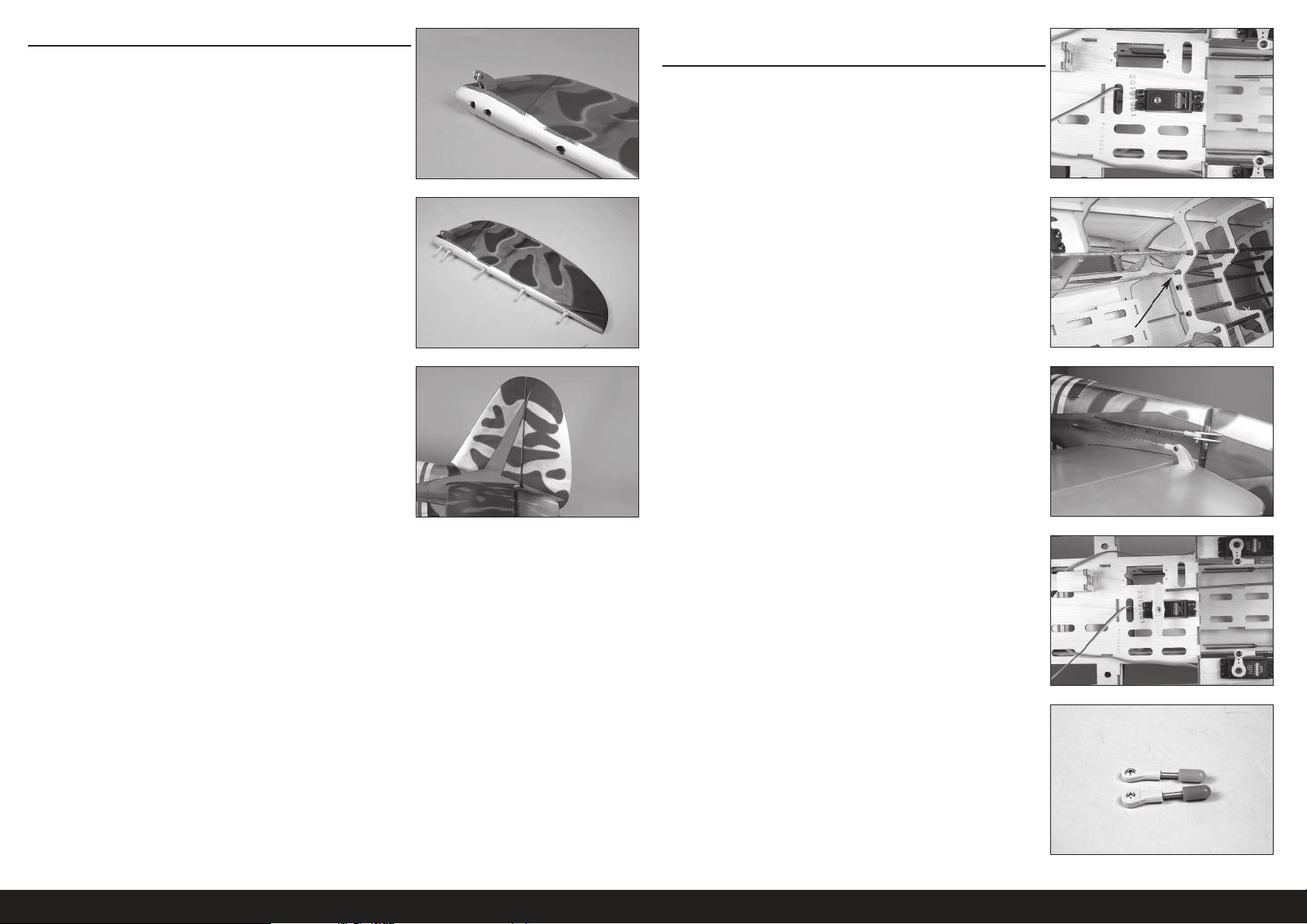
INSTALLATION DE LA GOUVERNE DE DIRECTION
1. Installez les renvois de commande de la gouverne de direction.
Leur installation est identique à celle des renvois de commande de
l’aileron. Assurez-vous d’installer les renvois de commande de la
gouverne de direction du bon côté de la gouverne de direction.
Vérifiez bien que les renvois de commande de la gouverne de
direction sont fermement collés après séchage complet de la colle.
2. Collez les charnières dans la gouverne de direction avec une colle
époxy 30 minutes. L’installation des charnières de gouverne de
direction suit la même procédure que les charnières d’aileron.
INSTALLATION DE LA TRINGLERIE DE LA GOUVERNE DE
DIRECTION
1. Préparez les trous dans le fuselage pour le servo de gouverne de
direction en vissant une vis dans chaque trou. Retirez les vis et
appliquez 2 à 3 gouttes de CA fi ne dans chaque trou pour durcir la
structure de bois qui l’encadre. Une fois la CA entièrement séchée,
installez le servo de gouverne de direction avec l’arbre du servo
orienté vers l’avant du fuselage.
1
2. Faites glisser une barre de liaison de 1020mm (40
le tube de barre de liaison.
/8 pouces) dans
3. Collez les charnières à la dérive avec une colle époxy 30 minutes.
Vérifiez bien que les charnières de la gouverne de direction
sont fermement collées après séchage complet de la colle.
3. Vissez une extrémité à bille à 12tours sur la barre de liaison.
Fixez l’articulation à bille du servo au renvoi de commande à l’aide
d’une vis à tête bombée M3 x 10, d’un contre-écrouM3 et d’une
rondelleM3. Utilisez une clé à six pans de 2,5mm et un tournevis à
écrou de 5,5mm pour le serrage du matériel.
4. Centrez le servo de la gouverne à l’aide du système radio. Placez le
bras de servo sur le servo de manière à ce qu’il soit perpendiculaire
à la ligne de centre du servo. Il peut être nécessaire de pivoter le
bras de 180 degrés pour mieux l’aligner sur le servo. Marquez le
bras afi n de pouvoir le remettre en position sur le servo.
5. Vissez une extrémité à bille à 12tours sur un raccord de câble. À ce
stade, préparez deux raccords de câble.
92FR
Page 93
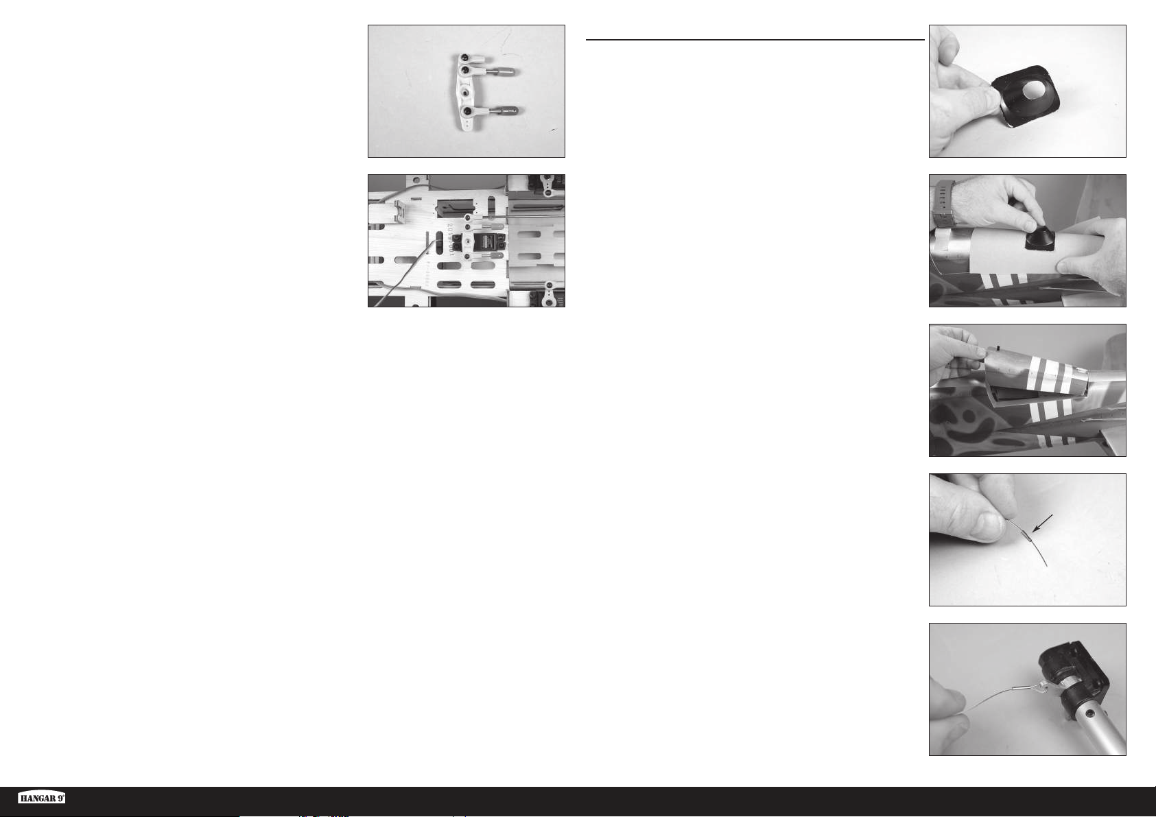
6. Fixez une extrémité à bille, et les deux extrémités à bille avec les
raccords de câble, au bras de servo de la gouverne de direction.
Utilisez trois vis à tête bombée M3 x 10, trois rondelles M3 et trois
contre-écrous M3. Utilisez une clé à six pans de 2,5mm et un
tournevis à écrou de 5,5mm pour le serrage du matériel.
INSTALLATION DE LA ROUE DE QUEUE
1. Utilisez des ciseaux pour tailler le carénage du train de queue.
L’installation du carénage de train de queue est facultative.
7. Vissez la barre de liaison dans l’extrémité à bille sur le bras de
servo. Avec le système radio allumé, ajustez la tringlerie de manière
à ce que la gouverne de direction soit centrée lorsque le bras est sur
le servo. N’installez pas la vis du bras de servo à ce stade.
2. Placez un papier abrasif à grain moyen contre le fuselage. Poncez
légèrement le carénage du train de queue pour que sa forme
corresponde au fuselage.
3. Faites glisser le loquet vers l’arrière du fuselage et retirez le cache
du train de queue. Mettez le cache de côté.
4. Faites glisser un manchon sur une extrémité du câble.
Ki-43 Oscar 60cc ARF
5. Faites passer le câble par le trou dans le bras de la roue de queue.
Passez à nouveau le câble par le manchon.
93 FR
Page 94
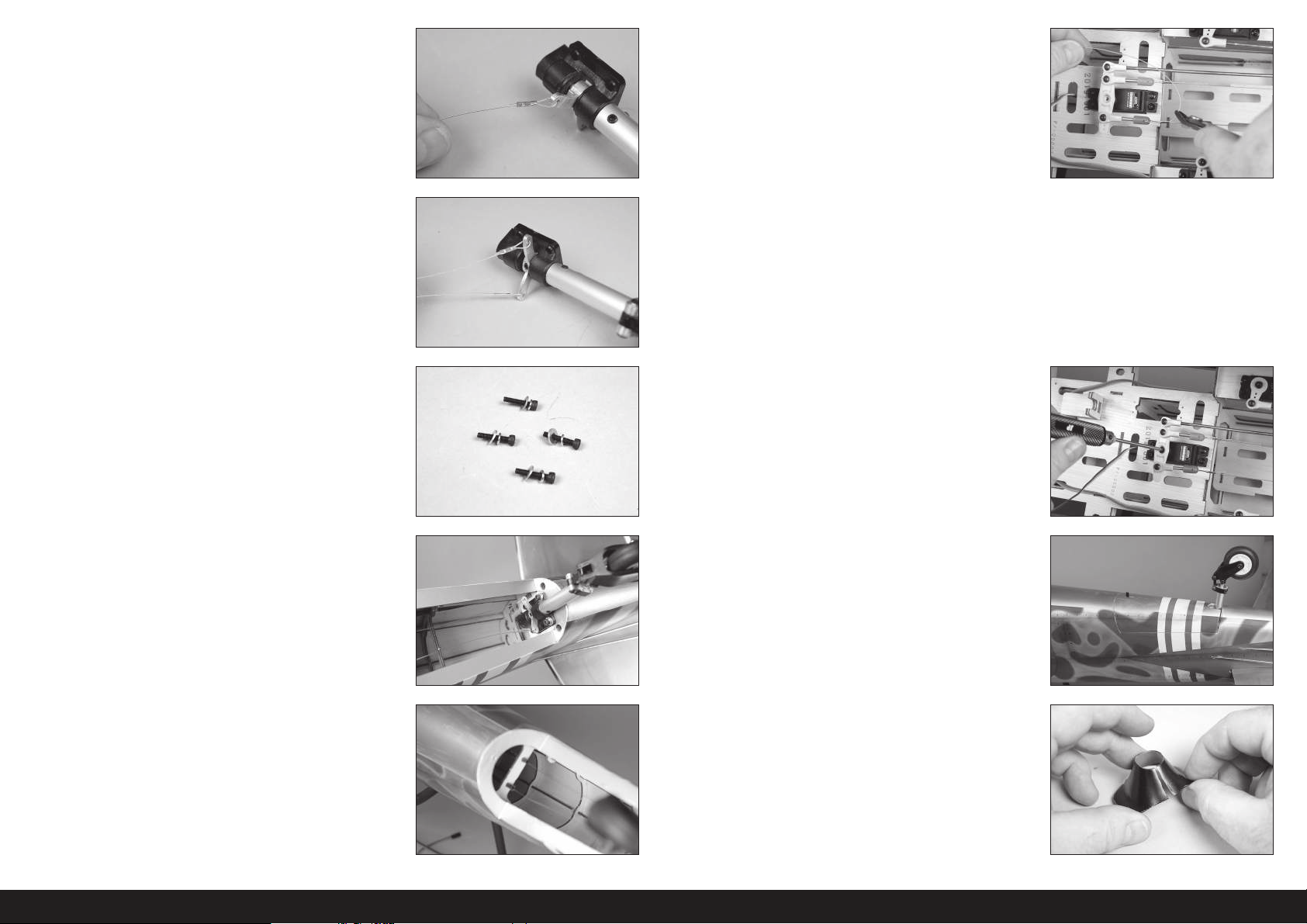
6. Utilisez une pince à sertir pour fi xer le manchon au câble.
Veillez à ne pas appuyer trop fort et à ne pas couper
le manchon au lieu de le fixer au câble.
11. Faites glisser un manchon sur une extrémité du câble. Faites passer
le câble par le trou dans le raccord du câble. Passez à nouveau le
câble par le manchon. Avec le servo de gouverne de direction et la
roue de queue centrés, appliquez une légère tension sur le câble.
Utilisez une pince à sertir pour fi xer le manchon au câble.
Le bras du servo peut être retiré du servo si nécessaire.
Veillez à ne pas appuyer trop fort et à ne pas couper
le sertissage au lieu de le fixer au câble.
7. Répétez le processus pour fi xer le câble restant au bras de la roue
de queue.
8. Faites glisser un écrou de blocage M3, puis une rondelle M3 sur une
vis d’assemblage creuse M3x15. Préparez les quatre vis.
9. Appliquez une goutte de frein-fi let sur chaque vis. Fixez le support
de roue de queue au fuselage en utilisant les vis de l’étape
précédente et une clé à six pans de 2,5mm.
Répétez le processus pour fixer les deux câbles.
Les câbles peuvent légèrement s’étendre au fil du
temps. Vérifiez régulièrement les câbles pour vous
assurer qu’il y a toujours une légère tension.
Utilisez une pince coupante pour tailler tout excédent de câble pouvant
interférer avec le fonctionnement de la maquette.
12. Fixez le bras du servo de la gouverne de direction avec la vis fournie
avec la gouverne de direction.
13. Remettez le cache de roue de queue sur le fuselage.
10. Glissez les câbles dans les tubes dans le fuselage. Récupérez les
câbles à l’intérieur du fuselage.
14. Utilisez des ciseaux pour découper une fente dans le carénage de
manière à pouvoir le placer sur l’ensemble de roue de queue.
94FR
Page 95
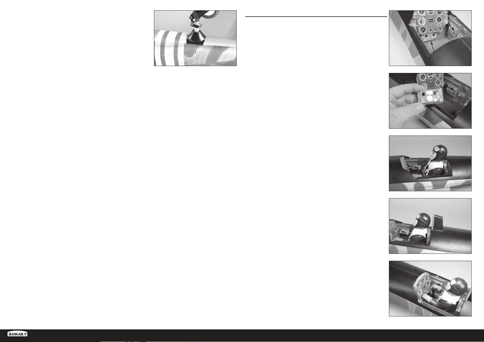
15. Collez le carénage de roue de queue au cache de roue de queue
avec une colle de contact. Veillez à ne pas coller le cache sur le
fuselage au cas où le cache devrait être retiré afi n d’accéder au
train de queue.
INSTALLATION DU PILOTE ET DE LA VERRIÈRE
1. Vous devrez retirer la partie inférieure du panneau d’instruments
pour installer le pilote dans le cockpit.
Il peut ne pas être nécessaire de retirer la partie inférieure
du panneau d’instruments sur les modèles de fabrication.
2. Retirez doucement le panneau d’instruments inférieur avec un
couteau et une lame nº11.
3. Utilisez un adhésif de contact pour coller le pilote au cockpit. Avant
de continuer, laissez la colle sécher complètement.
Ki-43 Oscar 60cc ARF
4. Collez l’appuie-tête en place avec une colle CA moyenne ou une
colle de contact.
5. Collez le manche de commande dans le cockpit avec une colle CA
moyenne ou une colle époxy 5 minutes. Positionnez le manche de
commande près des mains du pilote une fois le pilote installé.
95 FR
Page 96
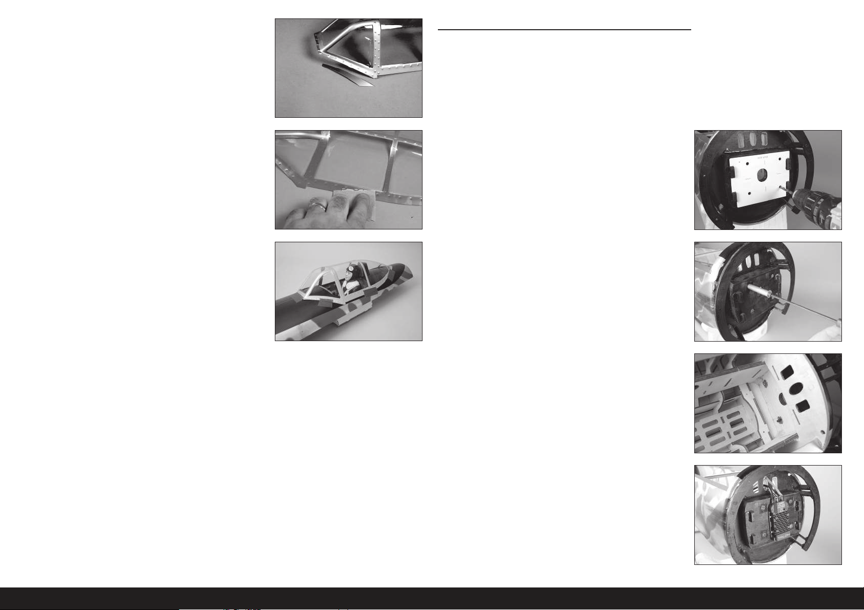
6. Il peut être nécessaire de tailler l’excédent de matériau de la
verrière. Utilisez des ciseaux pour tailler la verrière, puis utilisez un
papier abrasif à grain moyen pour lisser les bords.
INSTALLATION DU MOTEUR ÉLECTRIQUE
Comme beaucoup de maquettes d’avions de chasse, le Ki-43 Oscar
a un moment de nez court. Il peut être nécessaire d’ajouter du
poids au nez en fonction du système d’alimentation utilisé. Faites
attention à cela lors de l’assemblage et essayez de maintenir tous
les composants autant en avant dans le fuselage que possible.
7. Utilisez un papier abrasif à grain moyen pour poncer légèrement le
bord intérieur de la verrière là où il entre en contact avec la trappe
de la verrière. Nettoyez la zone poncée à l’aide de papier absorbant
imprégné d’alcool isopropylique pour enlever toute trace d’huile ou
d’impuretés. Cela permet d’obtenir la texture de surface nécessaire
pour l’adhérence de la colle.
8. Utilisez une colle pour verrière ou une colle de contact pour coller
la verrière à la trappe de la verrière. Utilisez du ruban adhésif pour
maintenir la verrière en place jusqu’au séchage complet de la colle.
N’utilisez pas de CA pour coller la verrière. Lorsque
la colle CA sèche, elle libère des gaz qui peuvent
embuer la verrière et altérer son aspect.
1. Placez le modèle de montage sur le pare-feu. Utilisez du ruban
à faible adhérence pour maintenir le modèle en place. Utilisez
une perceuse et une mèche de 6mm (1/4po) pour percer les
quatretrous dans le pare-feu permettant de fi xer le moteur.
Lorsque vous utilisez des systèmes électriques autres
que ceux recommandés, nous vous conseillons d’utiliser
le modèle de montage comme test pour vérifier
l’alignement des trous avant de percer le pare-feu.
2. Utilisez les vis et les entretoises pour attirer les écrous borgnes dans
le pare-feu depuis l’intérieur du fuselage.
3. Soudez les connecteurs nécessaires pour raccorder le variateur de
vitesse au moteur et à la batterie. Fixez le variateur de vitesse au
pare-feu à l’aide de vis ou de colliers de serrage.
96FR
Page 97
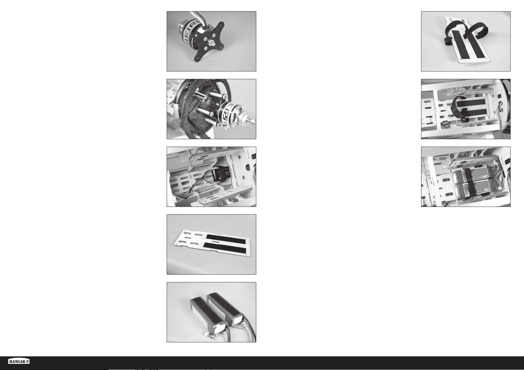
4. Fixez le support au moteur à l’aide de la quincaillerie fournie avec
le moteur. Déposez une goutte de frein-fi let sur chaque vis pour les
empêcher de se desserrer.
9. Utilisez des bandes velcro autour du support de batterie pour fi xer
les batteries au support.
Appliquez une petite quantité de colle époxy 5minutes sur les
sangles pour les fixer au support de batterie. Cela les empêchera
de tomber dans les trous lorsque la batterie est retirée.
5. Fixez votre moteur au pare-feu à l’aide des entretoises en aluminium
et des vis. Déposez une goutte de frein-fi let sur chaque vis pour les
empêcher de se desserrer. Connectez les fi ls entre le variateur de
vitesse et le moteur. Fixez les câbles de sorte qu’ils n’interfèrent pas
avec le fonctionnement du moteur.
6. Fixez la batterie pour le système radio dans la partie inférieure du
fuselage. Utilisez des bandes et des sangles velcro pour maintenir
la batterie.
7. Appliquez une fi ne couche de colle époxy 5 minutes sur le support
de batterie où les bandes velcro seront fi xées. Laissez la colle époxy
sécher entièrement avant d’appliquer la bande velcro au support de
batterie.
L’adhésif de la bande velcro n’adhérera pas au bois
brut. L’utilisation de colle époxy crée une surface
adaptée à l’adhésif de la bande velcro.
10. Préparez et durcissez les trous dans le fuselage pour les vis du
support de batterie à l’aide d’une vis à tôle M3 x 15 et de colle CA
fi ne. Fixez le support de batterie au fuselage à l’aide de quatre vis à
tôle M3 x 15 et de quatre rondelles M3.
11. Fixez les batteries dans le fuselage à l’aide des bandes velcro. Il
est possible d’ajuster l’emplacement des batteries pour aider à
équilibrer la maquette.
8. Appliquez la bande velcro correspondante sur les batteries.
Ne masquez pas les avertissements en matière de
sécurité de la batterie avec la bande velcro.
Ki-43 Oscar 60cc ARF
97 FR
Page 98
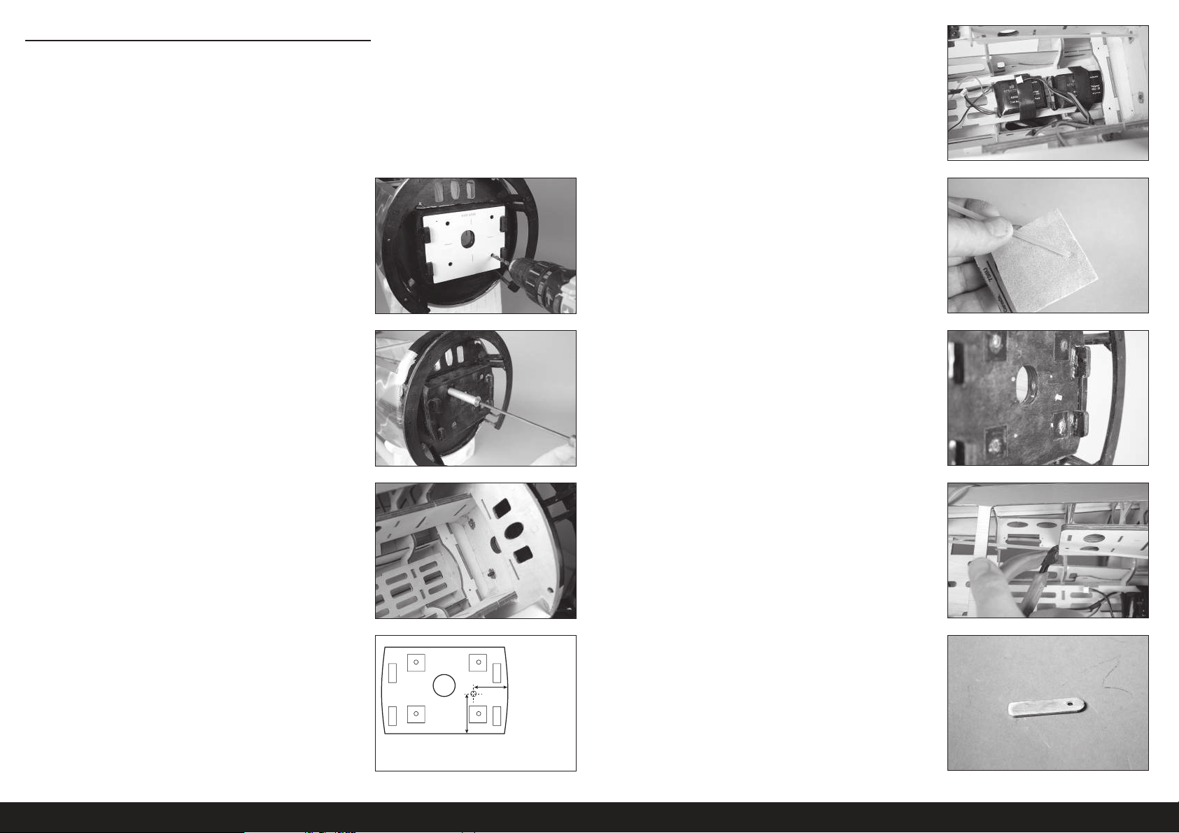
INSTALLATION DU MOTEUR À ESSENCE
Comme beaucoup de maquettes d’avions de chasse, le Ki-43 Oscar
a un moment de nez court. Il peut être nécessaire d’ajouter du
poids au nez en fonction du système d’alimentation utilisé. Faites
attention à cela lors de l’assemblage et essayez de maintenir tous
les composants autant en avant dans le fuselage que possible.
4. Fixez les batteries pour le système radio et l’allumage dans la partie
inférieure du fuselage. Utilisez des bandes et des sangles velcro
pour maintenir les batteries.
1. Placez le modèle de montage sur le pare-feu. Utilisez du ruban
à faible adhérence pour maintenir le modèle en place. Utilisez
une perceuse et une mèche de 6mm (1/4po) pour percer les
quatretrous dans le pare-feu permettant de fi xer le moteur.
Lorsque vous utilisez des systèmes électriques autres
que ceux recommandés, nous vous conseillons d’utiliser
le modèle de montage comme test pour vérifier
l’alignement des trous avant de percer le pare-feu.
2. Utilisez les vis et les entretoises pour attirer les écrous borgnes dans
le pare-feu depuis l’intérieur du fuselage.
5. Utilisez du papier abrasif à grain moyen pour légèrement poncer le
tube de la barre de liaison. Retirez toute huile ou tout débris du tube
avec du papier absorbant imprégné d’alcool isopropylique.
6. Faites glisser le tube par le trou dans le pare-feu. Laissez une
longueur de 6mm (1/4po) du tube exposée devant le pare-feu.
Utilisez une CA moyenne pour coller le tube en place.
7. Utilisez une pince coupante pour couper le tube de la barre de
liaison 5mm (3/16po) derrière le bord du côté intérieur du fuselage.
3. Utilisez une perceuse et une mèche de 3,5mm (9/64po) pour
percer le trou de la barre de liaison des gaz.
L’emplacement indiqué est pour le modèle Evolution62GX. Veillez
à bien localiser le tube des gaz si vous utilisez d’autres moteurs.
23/32 inches
(53mm)
121/32 inches
(42mm)
8. Utilisez une perceuse et une mèche de 3,5mm (9/64po) pour
percer un trou dans un manche de mélange. Coupez le manche
à une longueur de 38mm (1
1
/2po). Cela représentera le support
arrière du tube de la barre de liaison des gaz.
98FR
Page 99
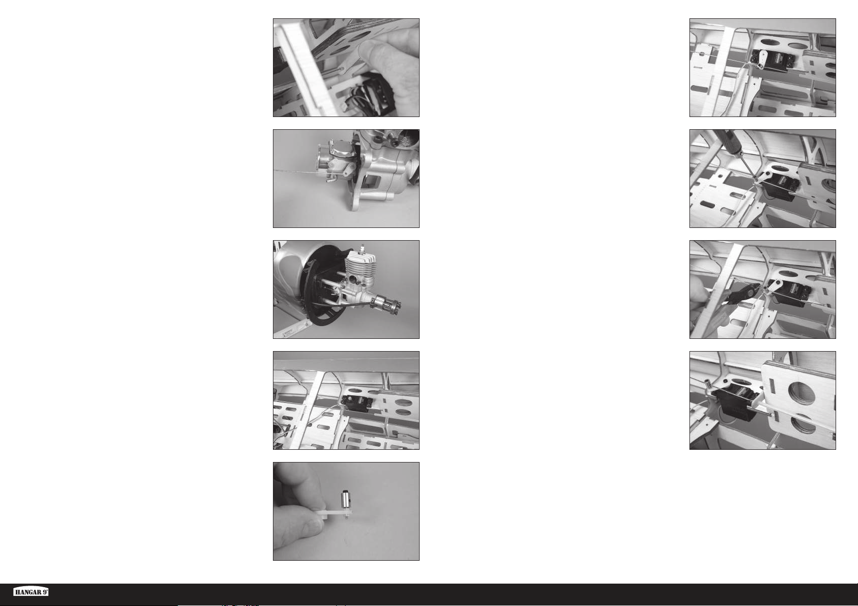
9. Glissez le support sur le tube de la barre de liaison. 14. Centrez le servo en utilisant le système radio, puis installez le bras
sur le servo de manière à ce qu’il soit perpendiculaire à la ligne
centrale de ce dernier. Veillez à glisser le connecteur sur le fi l de
barre de liaison. Utilisez une pince coupante pour supprimer tout
bras pouvant interférer avec le fonctionnement du servo.
10. Connectez la partie en Z dans la barre de liaison sur le bras du
carburateur.
11. Guidez la barre de liaison des gaz dans le tube de barre de liaison.
Fixez le moteur au pare-feu à l’aide de quatre entretoises, quatrevis
mécaniques, et quatrerondelles. Appliquez une goutte de frein-fi let
sur l’extrémité de chaque vis avant l’installation.
12. Préparez les trous dans le fuselage pour le servo des gaz en vissant
une vis dans chaque trou. Retirez les vis et appliquez 2 à 3 gouttes
de CA fi ne dans chaque trou pour durcir la structure de bois qui
l’encadre. Une fois la CA entièrement séchée, installez le servo des
gaz avec l’arbre du servo orienté vers l’arrière du fuselage.
15. Mettez le carburateur et le servo en position de gaz faibles et serrez
la vis de fi xation qui fi xe la barre de liaison sur le connecteur au
servo. Utilisez une pince coupante pour tailler l’excédent de câbles.
Vérifi ez le fonctionnement du carburateur à l’aide du système
radio. Apportez les ajustements nécessaires pour ouvrir et fermer
entièrement le carburateur à l’aide du système radio.
16. Utilisez une pince coupante pour supprimer tout excédent de fi l de
barre de liaison pouvant interférer avec le fonctionnement du servo
des gaz.
17. Utilisez une colle époxy 15 minutes pour coller le support de tube de
barre de liaison au bord arrière du côté intérieur du fuselage.
13. Montez le connecteur du servo des gaz dans le bras de servo des
gaz de manière à ce qu’il soit à 11mm (7/16po) du centre du bras
de servo. Mettez une goutte de colle pour verrière sur l’écrouM2
puis installez-le sur le côté inférieur du bras pour fi xer le connecteur.
Ki-43 Oscar 60cc ARF
99 FR
Page 100
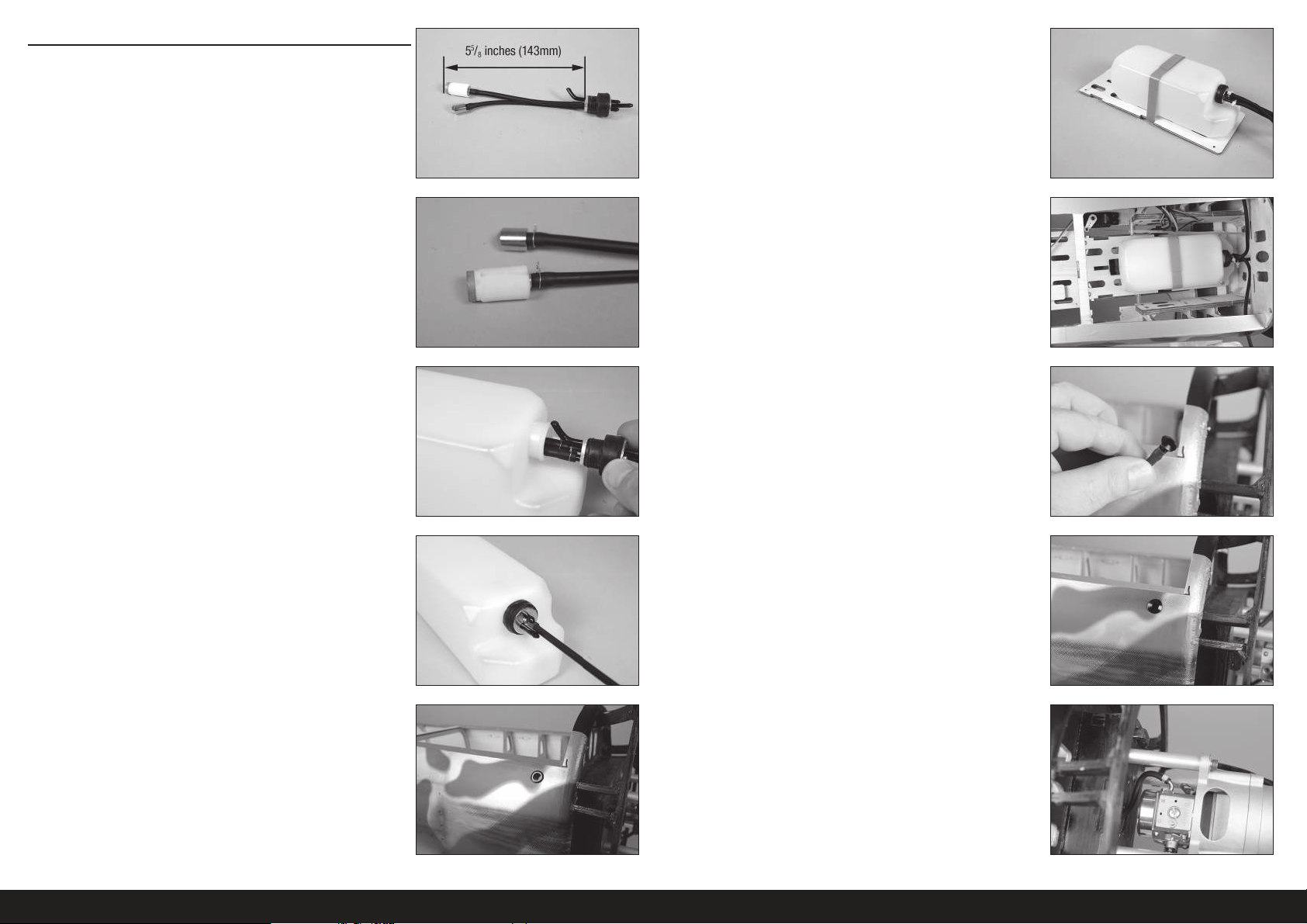
INSTALLATION DU RÉSERVOIR DE CARBURANT
1. Coupez une pièce de tube de carburant qui provoquera la fi n du
plongeur à 143mm (55/8po) de l’arrière de la plaque en aluminium.
6. Fixez le réservoir de carburant au support de réservoir de carburant
avec des sangles velcro Fixez des longueurs de 190mm (7
1
/2 po) de
ligne de carburant aux trois lignes qui sortent du réservoir. Utilisez
des colliers de serrage pour éviter que les lignes ne se desserrent.
2. Fixez la tuyauterie au plongeur et au bouchon à l’aide d’un fi l
fi n. Ceci permet d’éviter le glissement du tube dans le réservoir.
Assurez-vous d’utiliser le plongeur fourni avec votre moteur.
Un second plongeur peut être installé pour fournir une
ligne pour alimenter et vider l’appareil en carburant.
Nous recommandons l’utilisation d’un plongeur avec
un filtre pour toutes les installations de moteurs.
3. Insérez les plongeurs dans le réservoir. Installez le grand plongeur,
puis le petit plongeur. La ligne d’évent s’inclinera vers le sommet du
réservoir de carburant.
4. Identifi ez les lignes du réservoir, de sorte que les lignes de carburant
soient identifi ées depuis l’extérieur du réservoir. Serrez la vis dans le
bouchon à l’aide d’un tournevis cruciforme n°1.
Assurez-vous que les deux plongeurs peuvent bouger librement
dans le réservoir. Sinon, ajustez la tubulure depuis l’extérieur du
réservoir de sorte qu’ils puissent bouger librement pour assurer
qu’un flux cohérent de carburant circule jusqu’au moteur.
7. Préparez et durcissez les trous dans le fuselage pour les vis du
support de réservoir de carburant à l’aide d’une vis à tôle M3 x 15
et de colle CA fi ne. Fixez le support de réservoir de carburant au
fuselage à l’aide de quatre vis à tôle M3 x 15 et de quatre rondelles
M3.
8. Faites passer la ligne de remplissage à travers le raccord dans
le fuselage. Insérez le bouchon de remplissage dans la ligne de
remplissage partant du réservoir.
9. Appuyez le bouchon dans le raccord pour fi xer la ligne de
remplissage. Acheminez la ligne d’évent du réservoir vers le bas
du fuselage. Utilisez un raccord sous le fuselage pour fi xer la ligne
d’évent.
5. Utilisez un couteau avec une lame n°11 pour retirer l’entoilage
du fuselage pour le raccord de la ligne de remplissage. Installez le
raccord dans le fuselage.
La ligne de remplissage peut également être laissée à l’intérieur
du fuselage pour préserver l’aspect de la maquette. Vous devrez
retirer la trappe de la verrière pour remplir le réservoir de carburant.
10. Raccordez la ligne du bouchon à fi ltre vers le carburateur. Utilisez un
collier de serrage pour fi xer la ligne au carburateur.
Utilisez un filtre entre le réservoir de carburant et le
carburateur pour empêcher les débris pouvant se trouver dans
le carburant d’entrer dans le carburateur et le moteur.
100FR
 Loading...