

Page 1
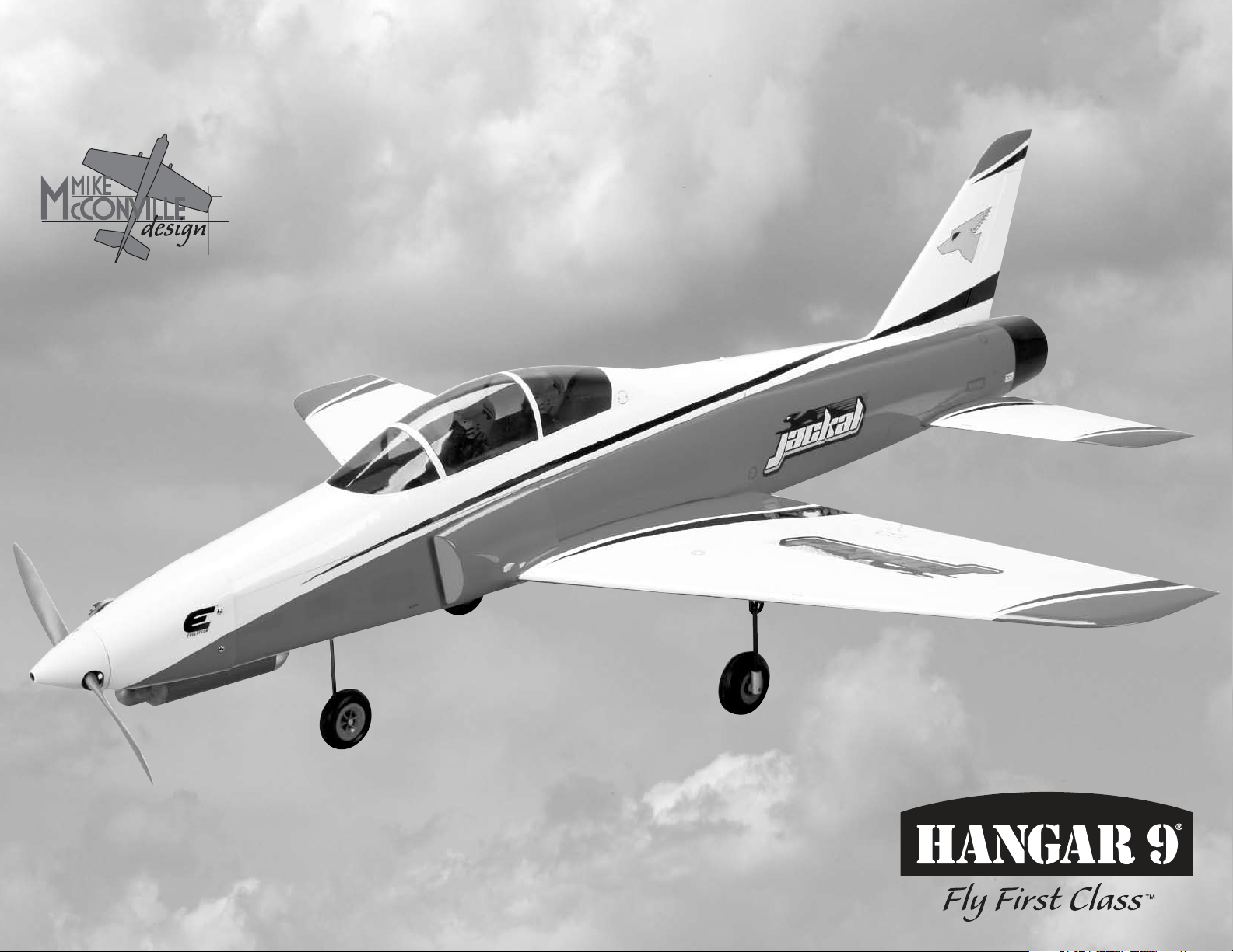
Jackal 50 ARF
Assembly Manual
Page 2
Notice
All instructions, warranties and other collateral
documents are subject to change at the sole discretion
of Horizon Hobby, Inc. For up-to-date product
literature, visit http://www.horizonhobby.com and click
on the support tab for this product.
Meaning of Special Language
The following terms are used throughout the product
literature to indicate various levels of potential harm
when operating this product:
NOTICE: Procedures, which if not properly followed,
create a possibility of physical property damage AND a
little or no possibility of injury.
CAUTION: Procedures, which if not properly followed,
create the probability of physical property damage AND a
possibility of serious injury.
WARNING: Procedures, which if not properly followed,
create the probability of property damage, collateral
damage, and serious injury OR create a high probability
of superficial injury.
WARNING: Read the ENTIRE instruction manual to
become familiar with the features of the product before
operating. Failure to operate the product correctly can result
in damage to the product, personal property and cause
serious injury.
This is a sophisticated hobby product and NOT a toy. It must
be operated with caution and common sense and requires
some basic mechanical ability. Failure to operate this Product
in a safe and responsible manner could result in injury or
damage to the product or other property. This product is not
intended for use by children without direct adult supervision.
Do not attempt disassembly, use with incompatible
components or augment product in any way without the
approval of Horizon Hobby, Inc. This manual contains
instructions for safety, operation and maintenance. It is
essential to read and follow all the instructions and warnings
in the manual, prior to assembly, setup or use, in order to
operate correctly and avoid damage or serious injury.
2 Hangar 9 Jackal 50 ARF
Notice ................................................................................2
Meaning of Special Language ...........................................2
Intro ..................................................................................2
Product Support ...............................................................2
Specifications ....................................................................2
Included Parts Listing .......................................................3
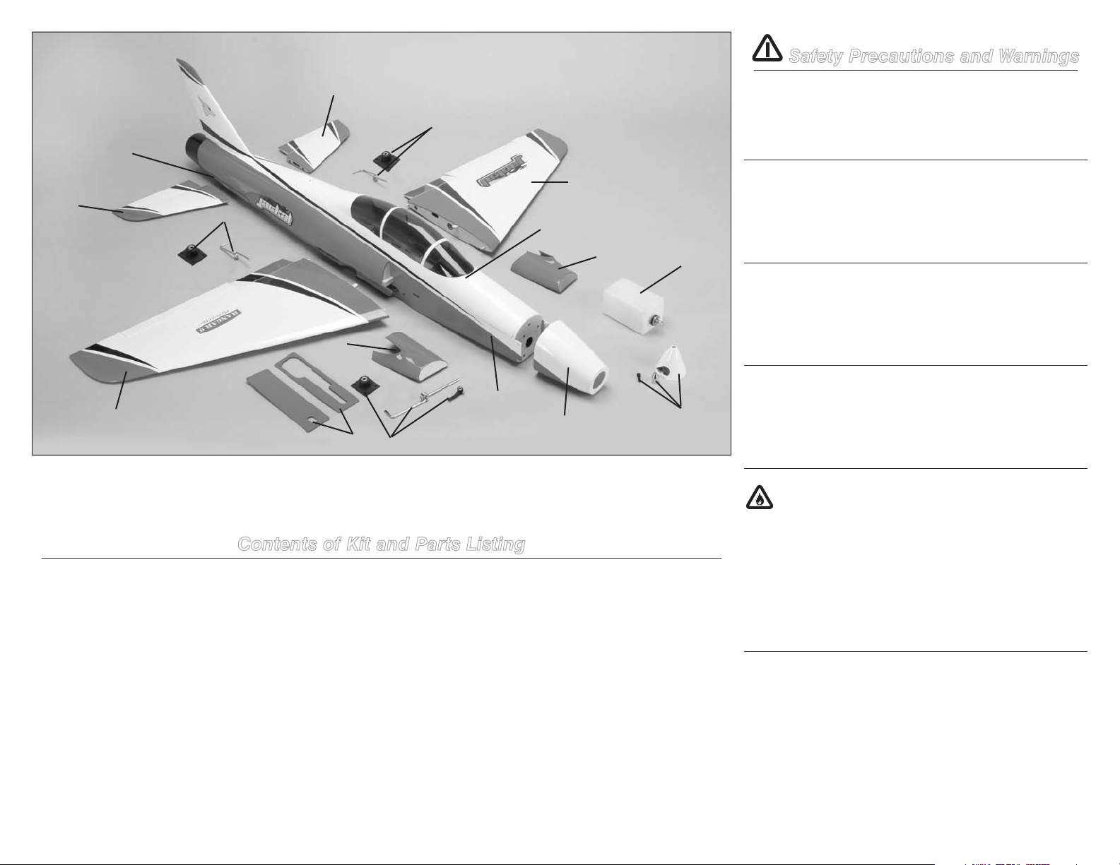
Contents of Kit and Parts Listing ......................................4
Safety Precautions and Warnings .....................................4
Important Information Regarding Warranty ......................5
Using the Manual ..............................................................5
UltraCote® Covering Colors .............................................5
Recommended Setup–2-Stroke Glow ...............................5
Transmitter Requirements.................................................5
Radio Equipment Requirements .......................................5
Optional Pilot ....................................................................5
Optional Pneumatic Retracts ............................................5
Optional Mechanical Retracts ...........................................5
Field Equipment Required .................................................5
Optional Field Equipment ..................................................6
Required Tools ..................................................................6
Required Adhesives ..........................................................6
Before Starting Assembly .................................................6
Elevator and Stabilizer Assembly ......................................6
Rudder Linkage and Receiver Installation .......................12
Stabilizer Assembly Installation ......................................15
Aileron Servo Installation ................................................16
Flap Servo Installation - Operational Flaps ......................18
Flap Stay Installation - Fixed Flaps ..................................21
Flap and Aileron Servo Linkage Installation ....................21
Nose Gear Installation - Fixed Gear.................................23
Nose Gear Installation - Mechanical Retract ...................26
Nose Gear Installation - Pneumatic Retract ....................32
Main Gear Installation - Fixed Gear .................................36
Main Gear Installation - Mechanical Retracts .................38
Main Gear Installation - Pneumatic Retracts...................43
Engine Installation ..........................................................47
Pneumatic Retract Valve and Air Line Installation ..........51
Wing Installation .............................................................54
Canopy Preparation and Pilot Installation .......................56
Center of Gravity .............................................................57
Control Throws ...............................................................58
Preflight ..........................................................................58
Range Test Your Radio ...................................................58
Safety Do’s and Don’ts for Pilots ....................................59
Daily Flight Checks ..........................................................59
Warranty and Repair Policy ............................................59
Warranty Services ...........................................................60
Compliance Information for the European Union ............60
2010 Official Academy of
Model Aeronautics Safety Code ...............................61
Table of Contents
The Jackal 50 ARF is a Mike McConville design capable of
reaching speeds in excess of 100 mph when using an engine
in the .50-.60 cu. in. range on a stock muffler. We highly
recommend the use of the Evolution® 60NX engine and
performance muffler (EVOM1) combination, as this really
allows the Jackal to perform to its fullest potential and reach
speeds in excess of 120 mph.. The removable top hatch
allows access to the radio equipment while the 2-piece wing
allows for easy transport. The optional Pneumatic Robart
Retracts (HAN502) provide additional performance and jetlike good looks.
Product Support
For technical assistance with this product, please contact the
appropriate Horizon Product Support office. See page 60.
Wingspan 63.0 in (160cm)
Length 56.0 in (142cm)
Wing Area 690 sq in (44.5 sq dm)
Weight 7.50–8.25 lb (3.40–3.80 kg)
Radio 5-channel (or greater) with 7 servos
Engine .52–.60 2-stroke
Intro
Specications
(6-channel or greater with 8–9 servos
if using retracts)
(small-case engine required)
Page 3
Included Parts Listing
PACKAGED INDIVIDUALLY LARGE BAGS
Fuselage with rudder, canopy hatch 1
Right wing with aileron and flap 1
Left wing with aileron and flap 1
Cowling and clear cowl template 1
Right horizontal stabilizer with elevator and hinges 1
Left horizontal stabilizer with elevator and hinges 1
Rear tail hatch 1
Fiberglass inlets left and right 2
FUSELAGE
2-56 Nylon clevis 3 Elevator (2) Rudder (1)
2mm white nylon clevis 1 Throttle
Silicone safety tubing 4 Elevator (2) Rudder (1) Throttle (1)
4-40 x 1-inch socket head cap screw 3 Rear elevator hatch to fuselage
#4 Black flat washers 3 Rear elevator hatch to fuselage
#4 lock washer 3 Rear elevator hatch to fuselage
Brass pushrod connector with setscrews 1 Throttle
4-40 x 3/8-inch chrome button head screw 4 Cowling to fuselage
Nylon torque link 3 Rudder (1) Elevator (2)
3mm x 8mm washer head wood screw 2 Inlet cheeks
1.7mm x 6mm washer head wood screw 2 Inlet cheeks
Servo extension safety clips 2 Elevator & receiver battery
WING
Aileron and flap servo covers 2 Left and right wing servos
17mm x 12mm x 10mm servo mounting blocks 8 Aileron and flaps
1.7mm x 6mm washer headed wood screws 12 Servo covers to wing
2-56 Nylon clevis 4 Aileron and flaps
Silicone safety tubing 4 Aileron and flaps
Wood & nylon brackets 2 Fixed flap stay
2.0mm x 15mm washer head wood screw 4 Fixed flap stay
4-40 x 5/8-inch socket head cap screw 2 Wing attachment
#4 black washers 2 Wing attachment
#4 lock washers 2 Wing attachment
3mm wood plates 2 Retract air line
LANDING GEAR
Landing gear base mount with setscrews 3 Fixed gear
Main gear struts with 4mm wire 2 Fixed gear
Nose gear strut with 4mm wire 1 Fixed gear
Nose gear steering arm with setscrew 1 Fixed gear
#6 x 1-inch wood screws 12 Landing gear mount
1
Hangar 9 Pro-Lite 2
/2-inch (63.5mm) wheel 2 Main gear
Hangar 9 Pro-Lite 21/4-inch (57mm) wheel 1 Nose gear
4mm wheel collars with setscrews 7 Wheel axles (6) nose wheel strut (1)
Wood mount 4 Retract valve mount
Nylon clevis 1 Retract
Safety tubing 1 Retract
2-56 x 2-inch (50mm) Pushrod 1 Retract
Wood adapter plate 1 Air retract servo mount
11mm x 7mm x 48mm blocks 2 Nose gear mount spacer
3mm x 8mm washer head wood screw 2 Retract valve mount
ENGINE MOUNT
Small black nylon motor mounts 2
8-32 x 3/4-inch socket head cap screws 4 Engine mount to firewall
#8 silver flat washers 4 Engine mount to firewall
6-32 x 1-inch socket head cap screw 4 Engine to mount
#6 silver flat washers 4 Engine to mount
6-32 nylon inserted lock nuts 4 Engine to mount
PUSHRODS
Elevator torque rods 2 Left and right elevator
1
2-56 x 4
/2-inch (114 mm) pushrod split end 1 Elevator
2-56 x 171/8-inch (435 mm) pushrod “Z” bend 1 Rudder
2-56 x 151/4-inch (387 mm) pushrod 1 Mechanical nose retract
2-56 x 61/2-inch (165mm) pushrod 2 Mechanical main gear retract
2mm x 31-inch (787 mm) pushrod 1 Throttle
2-56 x 2-inch (50 mm) pushrod 2 Flaps
2-56 x 3-inch (75 mm) pushrod 2 Ailerons
Small pushrod connector with setscrew & retainer 2 Nose wheel steering
Pull/Pull cable, 42-inch (1070mm) 1 Nose wheel steering
2-56 nut 3 Mechanical retracts
5/16-inch (8mm) copper tubes 4 Nose wheel steering crimps
Wire Pull/Pull cable end loops 2 Steering cables to the servo
5
/8-inch (218mm) Nylon pushrod housing 1 Nose wheel mechanical retract
8
MISC
Cockpit floor 1 Access to cockpit
9
/16 x 3/4-inch anodized black aluminum tube 1 Wing tube
13
103/8 x 5/16-inch anodized black aluminum tube 1 Horizontal stabilizer
53/4 x 5/16-inch anodized black aluminum tube 1 Horizontal stabilizer
1.5mm x 6mm washer headed wood screws 12 Cockpit floor and nose wheel cover
400cc 14 oz preplumbed fuel tank 1 Glow fuel tank
111/2 x 3/4-inch hook and loop straps 4 Battery receiver and fuel tank
Nose wheel fuselage plate 2 Retract (1) Fixed gear (1)
Decals 1
Instruction manual 1
3Hangar 9 Jackal 50 ARF
Page 4
Safety Precautions and Warnings
5
Read and follow all instructions and safety precautions
before use. Improper use can result in fire, serious injury
6
12
3
5
6
2
8
10
and damage to property.
COMPONENTS
Use only with compatible components. Should any
compatibility questions exist please refer to the product
instructions, the component instructions or contact Horizon
Hobby, Inc.
FLIGHT
Fly only in open areas to ensure safety. It is recommended
flying be done at AMA (Academy of Model Aeronautics)
approved flying sites. Consult local ordinances before
choosing a flying location.
8
PROPELLER
Keep loose items that can get entangled in the propeller
1
4
9
6
7
11
away from the prop, including loose clothing, or other
objects such as pencils and screwdrivers. Especially keep
your hands away from the propeller as injury can occur.
BATTERIES
Notes on Lithium Polymer Batteries
When used improperly, lithium polymer batteries are
Contents of Kit and Parts Listing
significantly more volatile than alkaline or Ni-Cd/Ni-MH
batteries used in RC applications. Always follow the
1. HAN488001 Fuselage with Hatch and Canopy
2. HAN488002 Fuselage Hatch and Canopy
3. HAN488003 Left Wing Panel
4. HAN488004 Right Wing Panel
5. HAN488005 Stabilizer and Elevator
6. HAN488006 Fixed Landing Gear without Wheels
7. HAN488007 Cowl
8. HAN488008 Fiberglass Inlets
9. HAN488009 Nose Wheel Cover Plate
10. HAN488013 14 oz (400cc)
11. HAN488019 Painted White 21/2-inch (63.5mm)
Aluminum Spinner
Items not shown
HAN488010 Anodized Aluminum Wing Tube
HAN488011 Pushrod Set
HAN488012 Decal Set
HAN488014 Wood Trays and Hatches
HAN488015 Aluminum Stabilizer Tubes
HAN488016 Steering Cables
HAN488017 Engine Mount
HAN488018 Complete Hardware Package
HAN488021 Cockpit Floor
HAN303 21/4-inch (57mm) Hangar 9 Wheels
HAN304 21/2-inch (63mm) Hangar 9 Wheels
manufacturer’s instructions when using and disposing of any
batteries. Mishandling of Li-Po batteries can result in fire and
explosion causing serious injury and damage.
SMALL PARTS
This kit includes small parts and should not be left
unattended near children as choking and serious injury
could result.
12. HAN488020 Rear Fuselage Hatch
4 Hangar 9 Jackal 50 ARF
Page 5

Safe Operating Recommendations
•Inspectyourmodelbeforeeveryflighttomakecertainit
is airworthy.
•Beawareofanyotherradiofrequencyuserwhomay
present an interference problem.
•Alwaysbecourteousandrespectfulofotherusersof
your selected flight area.
•Chooseanareaclearofobstaclesandlargeenoughto
safely accommodate your flying activity.
•Makecertainthisareaisclearoffriendsandspectators
prior to launching your aircraft.
•Beawareofotheractivitiesinthevicinityofyourflight
path that could cause potential conflict.
•Carefullyplanyourflightpathpriortolaunch.
•AbidebyanyandallestablishedAMANationalModel
Aircraft Safety Code.
Important Information
Regarding Warranty
Please read our Warranty and Liability Limitations section on
page 59 before building this product. If you as the purchaser
or user are not prepared to accept the liability associated
with the use of this Product, you are advised to return this
Product immediately in new and unused condition to the
place of purchase.
Using the Manual
UltraCote® Covering Colors
•WhiteHANU870
•TrueRedHANU866
•BlackHANU874
Recommended Setup–2-Stroke Glow
•Evolution
•APC10x7(APC10070)
•EvolutionHigh-PerformanceMuffler(EVOM1)
•Superplug(HAN3011)
®
.60NX with Muffler (EVOE0600)
Transmitter Requirements
This model requires a minimum of a 6-channel radio to
operate all the functions of your aircraft. We suggest the
following radio systems available through Horizon Hobby or
your local hobby distributor.
Spektrum DX6i SPM6600
JR® Systems X9503 2.4GHz JRP2930
JR Systems 12X 2.4GHz JRP1200
Radio Equipment Requirements
The following items are recommended when installing
the 7-Channel AR7000 (SPM6070) or 9-Channel AR9000
receiver (SPMAR9000) in your aircraft:
Optional Flaps: MN48 Servo (2)
•12-inchExtension(pluggedintoreceiver)(2)
•Y-harness(ifusing6-channelradioorless)
Elevator: DS821 Servo
•24-inchExtension(pluggedintoreceiver)
Rudder: DS821 Servo
Throttle: DS821 Servo
Optional Pilot
1/7-scale Jet Pilot (2) HAN9128
Optional Pneumatic Retracts
Robart Retracts, All-Metal Progressive HAN502
Robart Air Pump ROB164G
DS821 Servo JRPS821
Denatured alcohol
Optional Mechanical Retracts
Robart Retracts, All-Metal Progressive HAN501
RT88 Retract Servo (2) JSP20080
Y-harness JSP98020
JR Heavy-Duty Servo arm JRPA215
2-56 Quick Release Ball Link (2) SUL560
Denatured alcohol
This manual is divided into sections to help make assembly
easier to understand, and to provide breaks between each
major section. In addition, check boxes have been placed
next to each step to keep track of each step completed.
Steps with a single box () are performed once, while
steps with two boxes () indicate the step will require
repeating, such as for a right or left wing panel, two servos,
etc. Remember to take your time and follow the directions.
DS821 Digital Sport Servo (3) JRPS821
MN48 Mini Servo (2–4) JSP20040
9-inch Servo Extension (Receiver Battery) JRPA097
12-inch Servo Extension (4) (Ailerons/Flaps) JSP98030
24-inch Servo Extension (Elevator) JSP98040
Receiver Pack 2300mAh 6V Ni-MH JRPB5006
JR Chargeswitch JRPA004
Y-harness (Ailerons, 6-channel only) (2) JSP98020
Ailerons: MN48 Servo (2)
•12-inchExtension(pluggedintoreceiver)(2)
•Y-harness(ifusing7-channelradioorless)
Field Equipment Required
•Fuel(15%recommended)
•LongReachGlowPlugWrench(HAN2510)
•MeteredGlowDriverwithNi-Cd&Charger(HAN7101)
•2-CycleSportPlug(EVOGP1)
(For use with standard muffler)
•Superplug(HAN3011)(Forusewithhigh-performance
muffler, EVOM1)
•ManualFuelPump(HAN118)
The Spektrum trademark is used with permission
of Bachmann Industries, Inc.
All other marks are trademarks or registered
trademarks of Horizon Hobby, Inc.
5Hangar 9 Jackal 50 ARF
Page 6
Optional Field Equipment
Before Starting Assembly
Elevator and Stabilizer Assembly
•Self-stickweights,6oz(HAN3626)
•PowerPro
•12V7AhSealedBattery(HAN102)
•PowerPanel(HAN106)
•BlueBlockAfterRunOil(EVOX1001)
•Cleanerandtowels
™
12V Starter (HAN161)
Required Tools
Crimping tool Clamps
Drill Flat file
Hobby scissors Light machine oil
Low-tack tape Mixing cups
Mixing stick Felt-tipped pen
Nut driver: 5/16-inch Paper towels
Phillips screwdriver: #1, #2 Pencil
Pin vise Rotary tool
Cutoff wheel Sanding drum
Rubbing alcohol Ruler
Side cutter String
Toothpicks T-pins
Petroleum jelly Epoxy brush
Medium grit sandpaper Clear tape
Pliers
Needle nose pliers or hemostats
Ball driver or hex wrench: 1.5mm, 5/64-inch, 3/32-inch,
7/64-inch, 1/8-inch, 4mm
Drill bit: 1/16-inch (1.5mm), 5/64-inch (2mm),
3/32-inch, 7/64-inch (2.5mm), 1/8-inch (3mm),
9/64-inch (3.5mm), 3/16-inch (5mm)
Before beginning the assembly of your model, remove
each part from its bag for inspection. Closely inspect the
fuselage, wing panels, rudder and stabilizer for damage. If
you find any damaged or missing parts, contact the place of
purchase.
If you find any wrinkles in the covering, use a heat gun or
covering iron to remove them. Use caution while working
around areas where the colors overlap to prevent separating
the colors.
HAN100 – Heat Gun
HAN150 – Covering Glove
HAN101 – Sealing Iron
HAN141 – Sealing Iron Sock
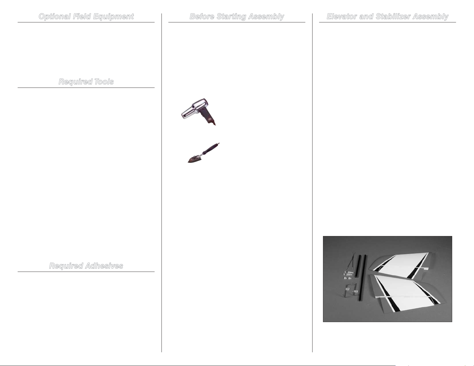
Required Parts
Stabilizer hatch cover
Clevis (2) Nylon torque rod horn (2)
Silicone clevis keeper (2) Split pushrod wire
Elevator torque rod (right and left)
Stabilizer/elevator assembly (right and left)
5/16 x 10
5/16 x 5
Required Tools and Adhesives
Thin CA 30-minute epoxy
Mixing cups Mixing sticks
Rubbing alcohol Paper towels
Toothpicks Low-tack tape
T-pins Pin vise
Petroleum jelly Phillips screwdriver: #1
Medium grit sandpaper Ruler
Medium grit sandpaper Pliers
Hobby knife with #11 blade Side cutters
Clear tape Receiver
Transmitter Receiver battery
Drill bit: 1/16-inch (1.5mm), 5/64-inch (2mm)
3
/8-inch (8mm x 263mm) anodized tube
3
/4-inch (8mm x 146mm) anodized tube
1. Locate the items for the elevator and stabilizer
assembly. You will also need to remove the stabilizer hatch
cover from the fuselage at this time.
Required Adhesives
Medium CA (PAAPT02)
Thin CA (PAAPT08)
Threadlock (PAAPT42)
30-Minute Epoxy, 8 oz (PAAPT39)
Zap-A-Dap-A-Goo similar or flexible adhesive
6 Hangar 9 Jackal 50 ARF
Page 7
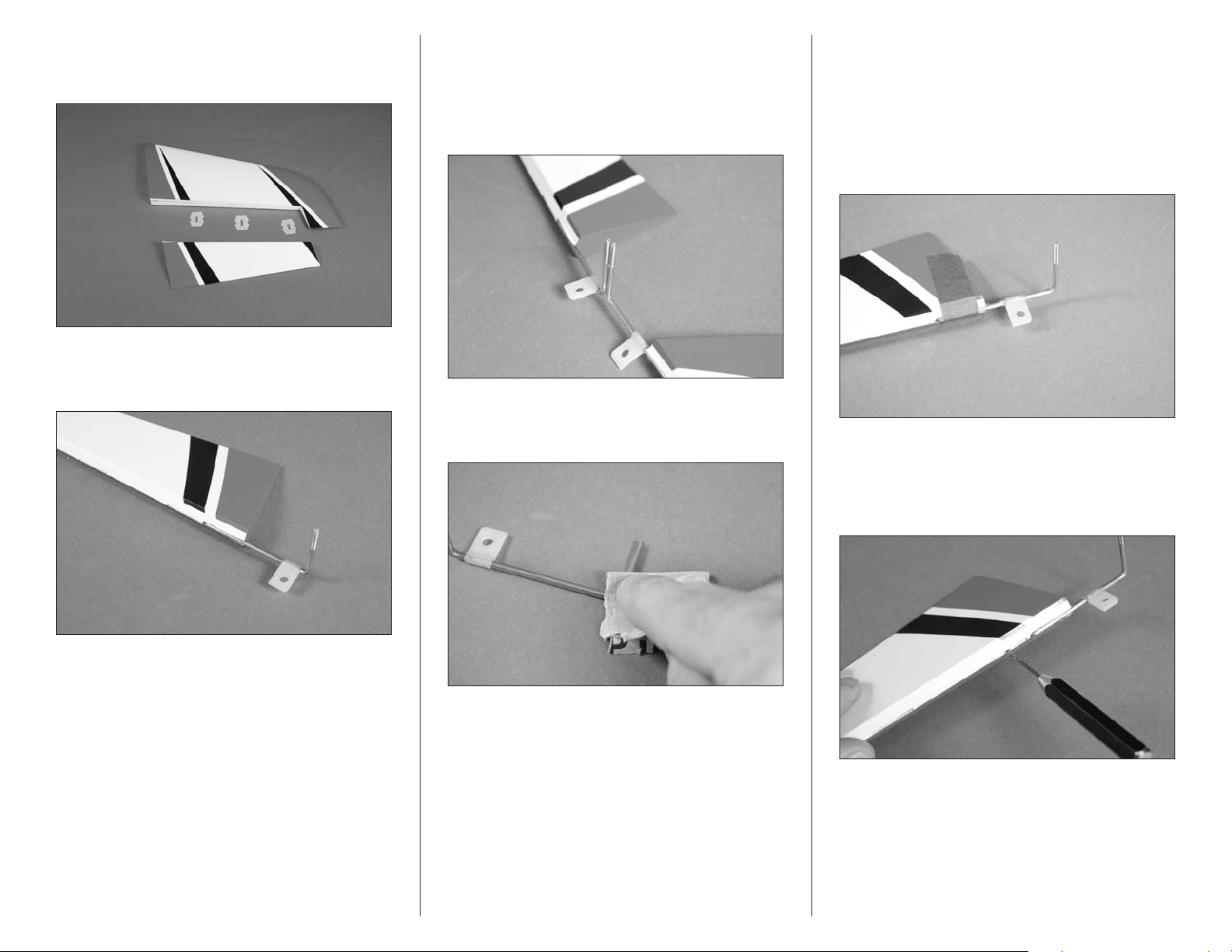
2. Separate the elevator and stabilizer. Set the three
hinges aside at this time. Prepare the left and right stabilizer
and elevator at this time.
3. Insert the elevator torque rod into the elevator. The rod
will fit tightly in the slot as shown. Note that the threaded
section of the torque rod faces to the top of the elevator.
4. Insert the torque rod in the remaining elevator. With
both elevators flat on your work surface, check to make
sure the threaded sections of the rods are parallel. If not,
slightly bend one of the torque rods until they are parallel.
Not checking the torque rods will result in uneven throw and
undesirable flight characteristics.
5. Once the torque rods are aligned, remove them from
the elevators. Use medium grit sandpaper to scuff the wire
where it contacts the elevator.
6. Use 30-minute epoxy to glue the torque rod to the
elevator. Use a toothpick to force the epoxy into the hole in
the leading edge of the elevator. Use low-tack tape to hold
the torque rod in position until the epoxy fully cures. Glue
the torque rods in both elevator halves at this time.
Note: Keep the nylon bushing slid away from the
elevator to avoid getting epoxy in the bushing.
7. Use a pin vise and 1/16-inch (1.5mm) drill bit to drill
a hole in the center of each hinge slot. This creates a tunnel
for the CA to wick into, creating a better bond between the
hinge and surrounding wood. Prepare both elevators and
stabilizers at this time.
7Hangar 9 Jackal 50 ARF
Page 8
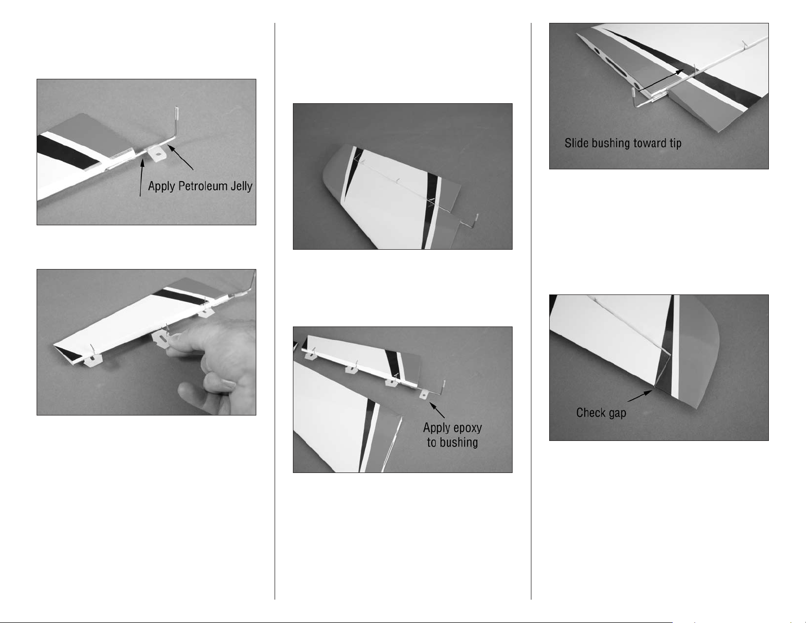
8. Apply a small amount of petroleum jelly to either side
of the bushing. Work the lubricant into the bushing to help
prevent epoxy from entering it when gluing the bushing to
the stabilizer.
Important: Hinge only one elevator to the stabilizer
at this time. The remaining stabilizer/elevator must be
left unhinged.
10. Check the fit of the elevator to the stabilizer. The
elevator should fit tightly against the stabilizer.
Important: Make sure the bushing does not extend
over the root edge of the stabilizer. If so, the stabilizer
will not fit correctly when installed.
9. Place a T-pin in the center of three hinges. Insert the
hinges into the elevator as shown.
11. Separate the elevator from the stabilizer. Attach
the elevator to the stabilizer by mixing a small amount of
30-minute epoxy and applying it to the nylon bushing to
secure the bushing to the stabilizer. Make sure to slide the
nylon torque rod bushing as close to the elevator as possible.
12. Remove the T-pins from the hinges. Position the
elevator so there is a 1/16-inch (1mm) gap between the tip
of the elevator and stabilizer. Saturate each of the hinges
on both the top and bottom of the hinge. Set the assembly
aside to cure.
8 Hangar 9 Jackal 50 ARF
Page 9
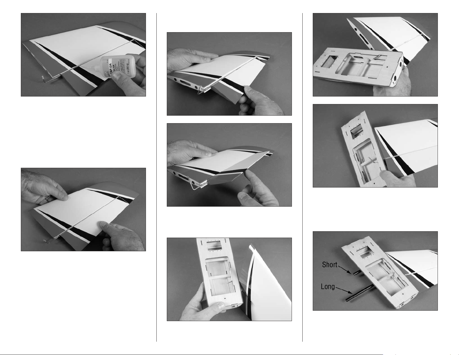
Important: Allow the CA to cure WITHOUT using CA
accelerator. This is necessary to allow the CA to soak
into the hinge, creating the best bond between the hinge
and surrounding wood.
13. Once the CA and epoxy has cured, check that all the
hinges are secure by gently trying to separate the elevator
from the stabilizer. If any hinges are loose, re-apply CA to the
loose hinges.
14. Break in the hinges by working the elevator up and
down a number of times.
15. Position the stabilizer in the stabilizer hatch cover.
Insert the torque rod through the slot, then rotate the
stabilizer and fit it into position.
16. Lightly sand the stabilizer tubes using medium grit
sandpaper. Use rubbing alcohol and a paper towel to remove
any oil or debris from the stabilizer tubes. Slide the tubes
through the stabilizer hatch. The shorter tube is near the
leading edge.
9Hangar 9 Jackal 50 ARF
Page 10
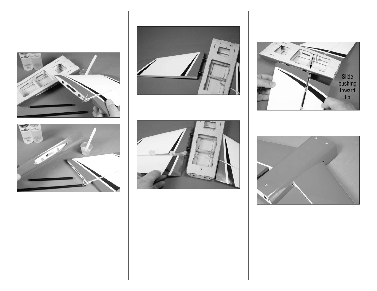
17. Now that the fit has been established, use 30-minute
epoxy to glue the stabilizer to the hatch, and the tubes in
the stabilizer. Disassemble the stabilizer, then apply epoxy in
the stabilizer sockets and the exposed wood. Apply a small
amount of epoxy in the tubes in the stabilizer hatch at this
time as well. Repeat Steps 15 and 16 to reassemble the one
stabilizer to the stabilizer hatch.
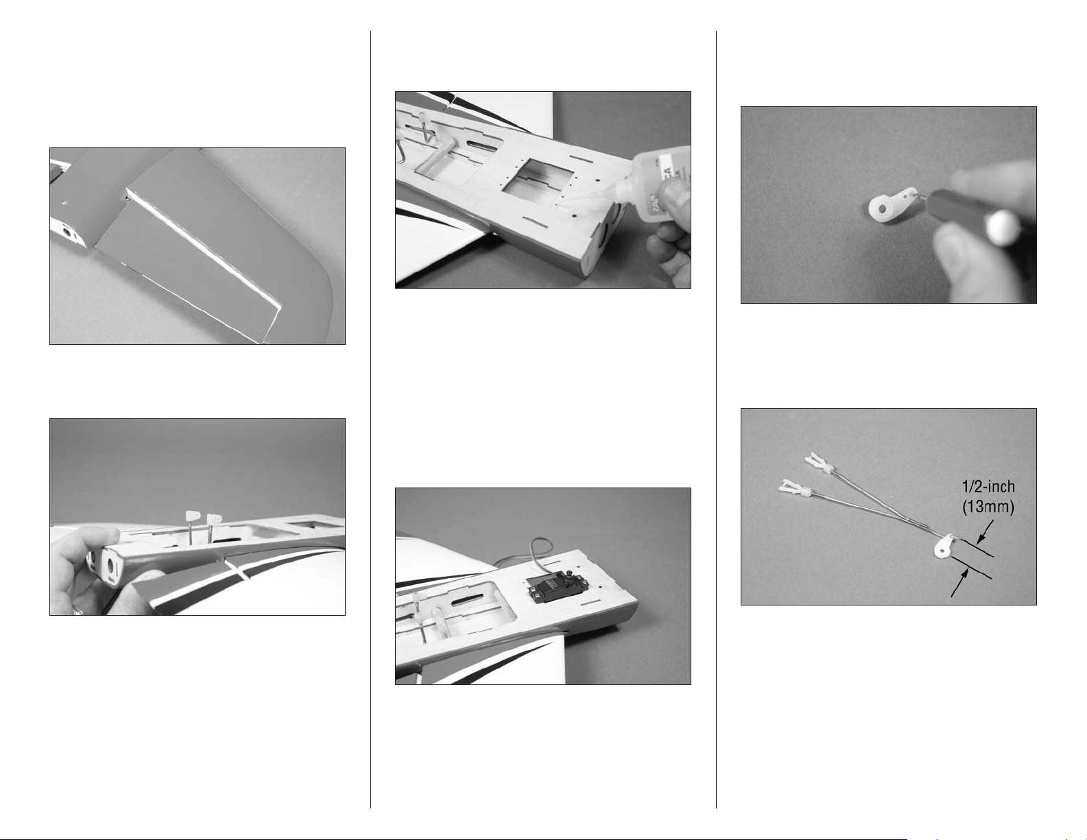
18. Slide the remaining stabilizer partially on the
stabilizer tubes.
19. Place a T-pin in the center of the three remaining
hinges and place them in the slots in the elevator. Insert the
torque rod into the stabilizer hatch.
20. You will need to position the stabilizer so the bushing
from the torque rod can be placed and the hinges installed.
Remember the torque rod bushing must be positioned as
close to the end of the elevator as possible or the stabilizer
won’t fit correctly.
21. Slide the stabilizer into position. It may be necessary
to use a hobby knife to lift the balsa on the bottom of the
stabilizer hatch to allow the stabilizer to fit into position.
Important: Check to make sure there is no epoxy on
the exposed tubes or base for the remaining stabilizer.
If there is, use rubbing alcohol and a paper towel to
remove it before it cures.
Note: Read through the next steps as the installation
of the remaining elevator and stabilizer does take
some finesse.
10 Hangar 9 Jackal 50 ARF
22. Now that the stabilizer has been fit, we can step
back and use epoxy to secure it into position. Remove the
stabilizer and apply epoxy to the stabilizer tubes and to the
exposed wood on the stabilizer root rib. When installing
the torque rod bushing, make sure to use epoxy on the
bushing and in the slot as well. Slide everything together and
remove the T-pins from the hinges. Check the gap between
the stabilizer and tip of the elevator so there is a 1/16-inch
(1mm) gap between the two.
Page 11
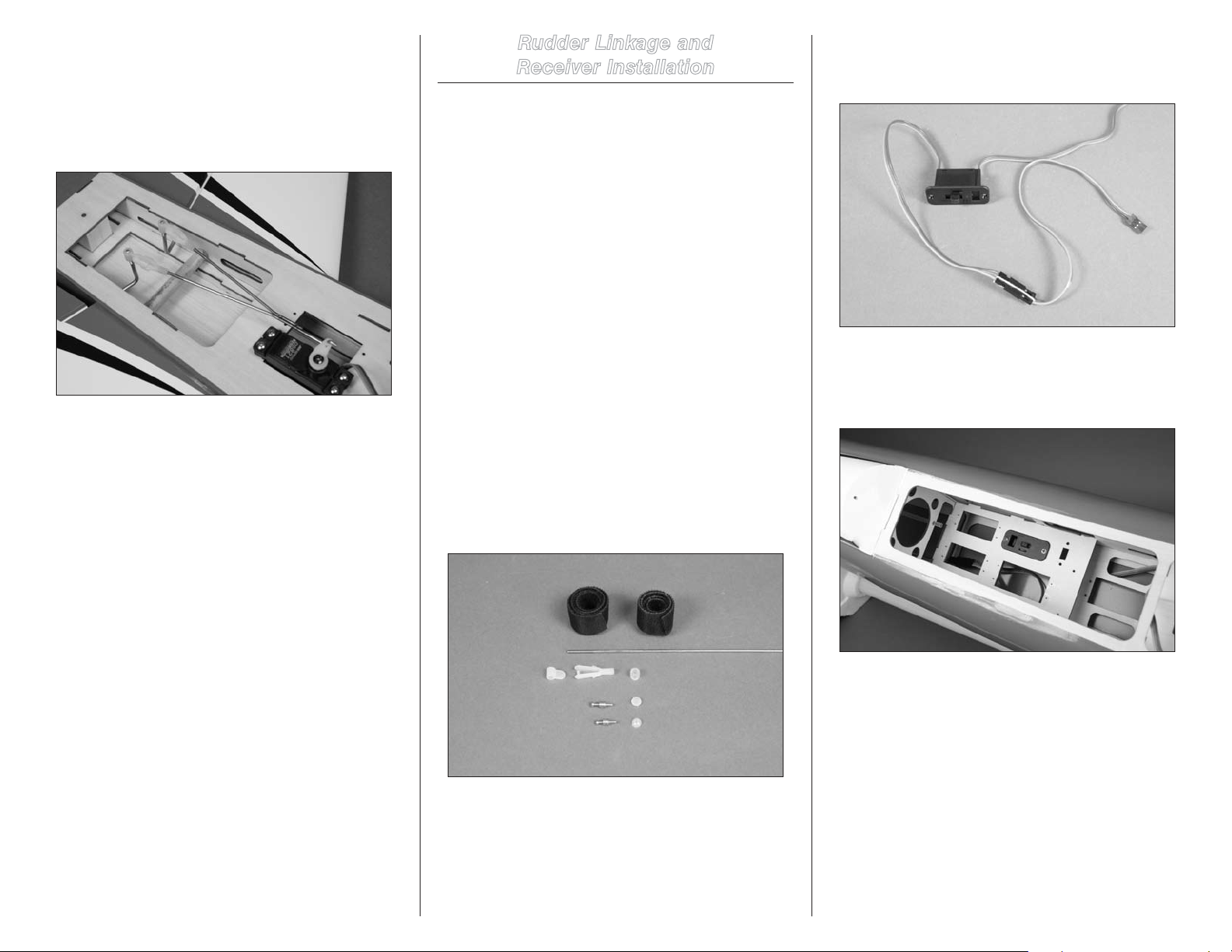
23. Use thin CA to glue the hinges. Make sure to check
and break them once the CA has fully cured.
24. At this time we recommend that you seal the hinge
gap between the elevator and stabilizer. Use either clear
covering or tape to seal the gap to prevent flutter of the
control surfaces during high-speed flight.
25. Thread the nylon torque rod horns on the threaded
ends of the torque rods. They will be flush with the top of
the threads as shown.
26. Place 2–3 drops of thin CA in each of the four holes
that will be used to mount the elevator servo. This will
harden the wood, making the screws more secure.
27. Remove the horn from the elevator servo. Install the
servo in the stabilizer hatch with the output facing away from
the elevators. Use the screws included with the servo to
secure it in the hatch. Make sure to install the grommets and
brass eyelets before securing the servo. Use a #1 Phillips
screwdriver to tighten the screws.
Note: Although there are two elevator servo positions,
we DO NOT recommend using two servos. This will add
too much weight to the rear of the fuselage, making it
difficult to balance your model.
28. Use a pin vise and 5/64-inch (2mm) drill bit to
enlarge the hole in the servo horn. Use side cutters to
remove any unused arms so they don’t interfere with the
operation of the servo.
29. Slide a silicone clevis keeper on a clevis. Thread the
clevis on the split pushrod wire. Prepare the pushrod wire
with two clevises as shown. Attach the bend in the pushrod
wire to a hole in the servo horn that is 1/2-inch (13mm)
from the center of the horn.
11Hangar 9 Jackal 50 ARF
Page 12
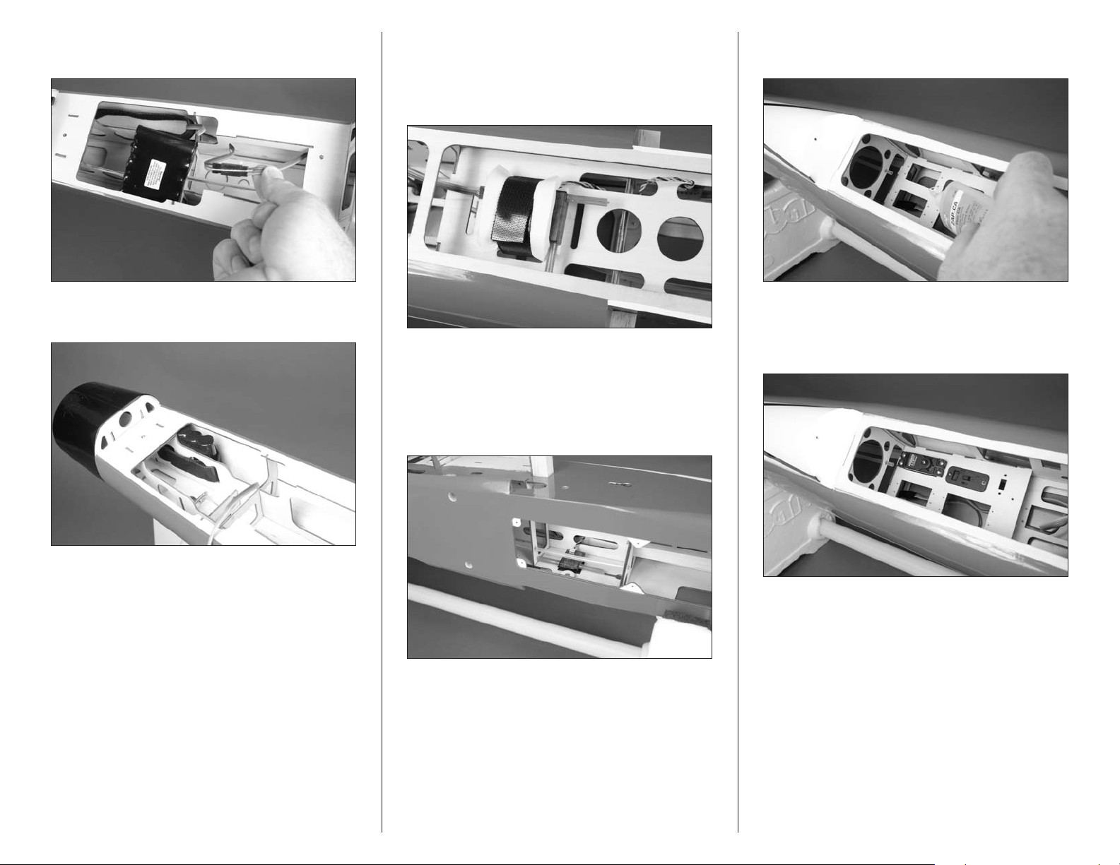
30. Center the elevator servo using the radio system.
Attach the servo horn to the elevator servo using the screw
provided with the servo. Connect the clevises to the nylon
torque rod horns. It will be necessary to adjust the clevis
to center both elevator halves. Once centered, slide the
silicone clevis keepers over the clevises to keep them from
opening accidentally.
Rudder Linkage and
Receiver Installation
Required Parts
Fuselage Clevis
Silicone clevis retainer Nylon torque rod horn
Receiver Hook and loop strap (2)
Receiver battery Switch harness
Transmitter
Hook and loop tape (not included)
1
17
/8-inch (435mm) pushrod with Z-bend
Brass pushrod connector (2)
Nylon connector backplate (2)
9-inch (228mm) servo extension
1/4-inch (6mm) foam rubber (not included)
Required Tools and Adhesives
Pin vise Thin CA
Phillips screwdriver: #1 Side cutter
String Ruler
Drill bit: 1/16-inch (1.5mm), 5/64-inch (2mm)
1. Locate the items to install the rudder linkage and
receiver. You will also need to have the fuselage and receiver
battery for this section of the manual.
2. Secure the 9-inch (228mm) servo extension to
the switch harness lead for the batery using string or a
commercially available connector.
3. Mount the switch in the fuselage by drilling two holes
for the mounting screws using a pin vise and 1/16-inch
(1.5mm) drill bit. Route the lead for the receiver under the
servo tray and to the rear of the fuselage.
Note: There are additional locations and sizes of
openings for switch locations in the radio tray and
fuselage sides. We prefer the location shown as it can
be checked visually.
12 Hangar 9 Jackal 50 ARF
Page 13
4. Secure the 9-inch (228mm) servo extension to the battery
pack lead using string or a commercially available connector.
6. Connect the lead from the switch to the receiver. The
receiver is secured in the fuselage using a hook and loop
strap. Make sure to use a piece of 1/4-inch (6mm) foam
between the plywood and receiver to prevent vibrations from
the airframe from entering the receiver.
8. Apply 2–3 drops of thin CA in the holes for the rudder
servo mounting screws.
5. Use a hook and loop strap to secure the receiver
battery in the rear of the fuselage.
7. Use hook and loop tape (not included) to mount the
remote receiver in the wheel well of the fuselage.
Note: We used short pieces of fuel tubing over the
antenna of the main and remote receivers to keep
them straight.
9. Remove the horn from the rudder servo. Use a #1
Phillips screwdriver and the screws provided with the servo
to mount the rudder servo in the fuselage. Note that the
output for the servo faces to the front of the fuselage.
13Hangar 9 Jackal 50 ARF
Page 14
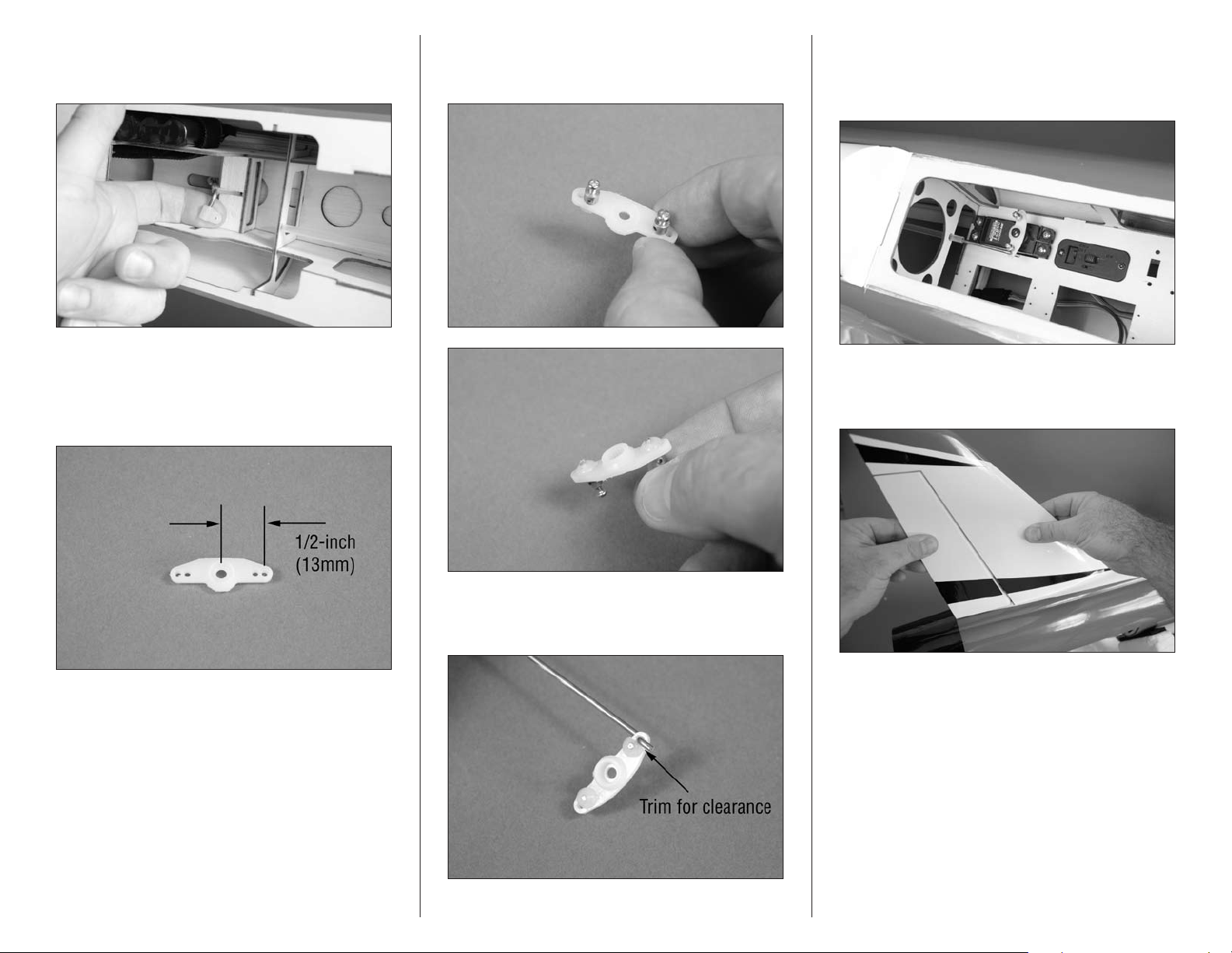
10. Thread the nylon torque rod horn onto the rudder
torque rod. The top of the horn will be flush with the end of
the threads as shown.
11. Locate a servo horn and enlarge the holes in the arm
as shown using a pin vise and 5/64-inch (2mm) drill bit. The
rudder pushrod will connect to a hole in the arm that is 1/2inch (13mm) from the center of the horn. Remove any arms
from the horn that will not be used.
12. Insert the brass pushrod connectors in the inner
holes as shown. Use a nylon connector backplate to secure
the connectors to the servo horn.
14. Insert the pushrod in the rudder tube inside the
fuselage. Center the rudder servo using the radio system.
Secure the horn to the rudder servo using the screw
previously removed.
15. Check that all the hinges are secure by gently
trying to separate the rudder from the fuselage. If any hinges
are loose, re-apply CA to the loose hinges.
13. Insert the Z-bend of the 17
in the outer hole of the servo horn. You will need to trim the
nylon backplate to provide clearance for the pushrod.
14 Hangar 9 Jackal 50 ARF
1
/8-inch (435mm) pushrod
Page 15
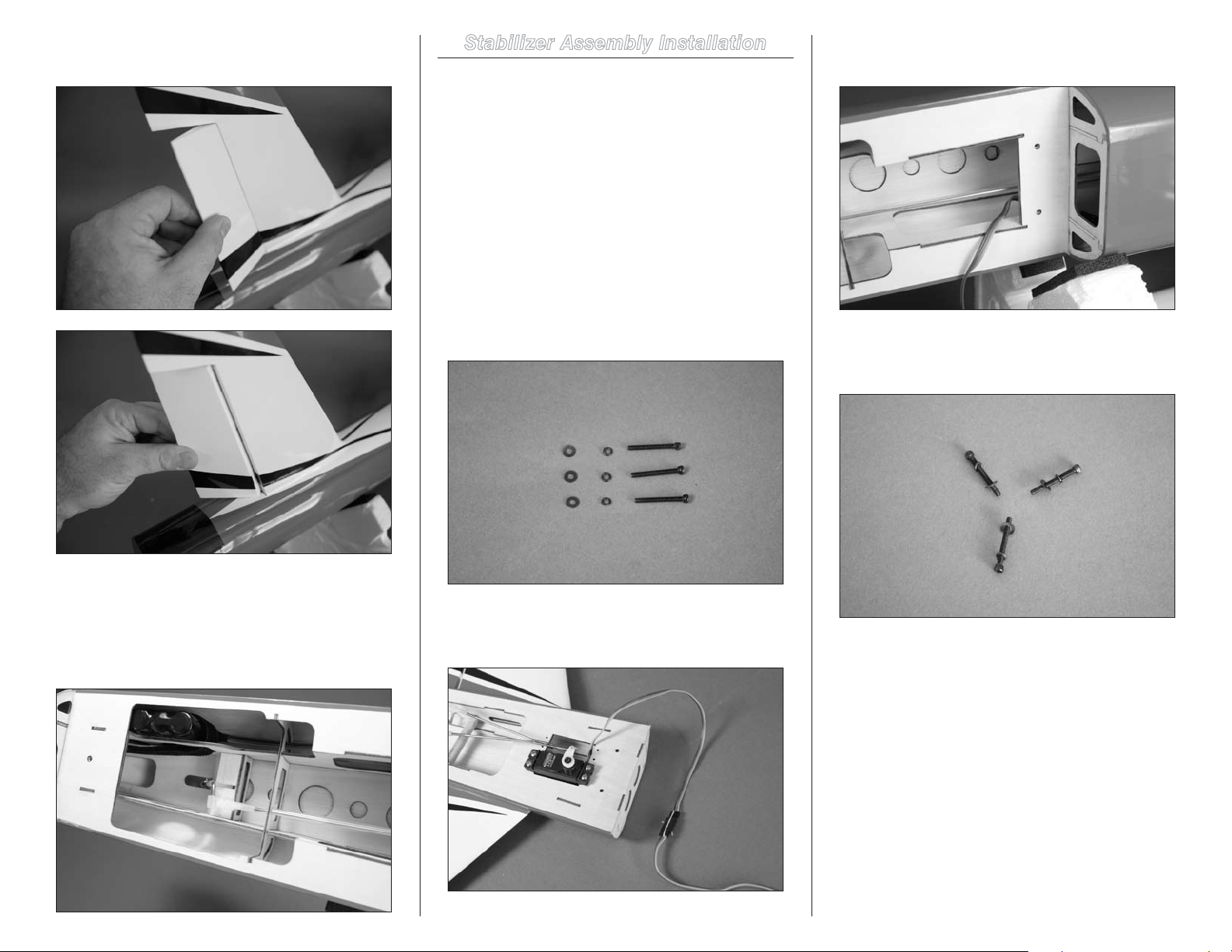
16. Break in the hinges by working the rudder right
and left a number of times.
Stabilizer Assembly Installation
Required Parts
Fuselage
#4 washer (3) #4 lock washer (3)
Stabilizer/elevator assembly
24-inch (610mm) servo extension
4-40 x 1-inch socket head machine screw (3)
Required Tools and Adhesives
String
Hex wrench or ball driver: 3/32-inch
1. Locate the hardware to attach the stabilizer assembly
to the fuselage. You will also need the fuselage and stabilizer
assembly at this time.
3. Pass the extension through the fuselage toward
the receiver.
4. Slide a lock washer then a standard washer on the
4-40 x 1-inch socket head machine screw. Prepare all three
screws at this time.
17. Slide a silicone clevis keeper over a nylon clevis.
Thread the clevis on the rudder pushrod. With the rudder
servo centered, check that when the clevis is attached to the
torque rod horn that the rudder is centered. Once complete,
slide the silicone keeper over the forks of the clevis to
prevent it from opening accidentally.
2. Use string or a commercially available connector to
secure the 24-inch (610mm) servo extension to the elevator
servo lead.
15Hangar 9 Jackal 50 ARF
Page 16
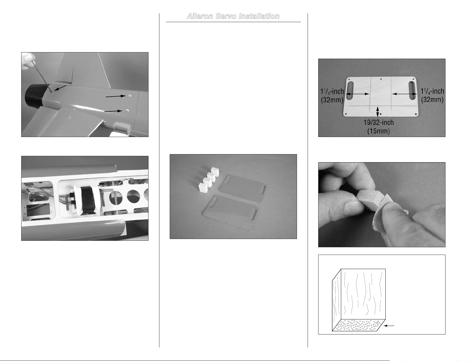
5. Position the stabilizer assembly on the fuselage.
Sand this end
Secure the assembly using the three screws prepared in the
previous step. Use a 3/32-inch hex wrench or ball driver
to tighten the screws. Make sure to use threadlock on the
screws so they don’t vibrate loose.
6. Plug the extension into the elevator port of the receiver.
Aileron Servo Installation
Required Parts
Servo cover (2) Receiver
Receiver battery
Servo with hardware (2) Transmitter
17mm x 12mm x 10mm servo mounting block (4)
Required Tools and Adhesives
Thin CA Medium grit sandpaper
30-minute epoxy Mixing stick
Pencil Side cutter
Pin vise Drill
Ruler Mixing cups
Drill bit: 1/16-inch (1.5mm), 5/64-inch (2mm)
1. Locate the servo covers and hardwood blocks to
mount the servos to the covers.
2. Use a pencil to draw two lines on the cover. The first
line is along the bottom of the cover, 19/32-inch (15mm)
from the edge. The second line is 11/4-inch (32mm) from the
side of the cover along both sides as shown. This will center
the servo horn in the slot when using the recommended
servos.
3. Lightly sand the end of the block using medium grit
sandpaper. Sand the end grain as shown in the drawing.
Note: If you are not using the recommended servos,
you will need to center the servo horn in the slot in the
cover and mark the location for the servo.
16 Hangar 9 Jackal 50 ARF
Page 17
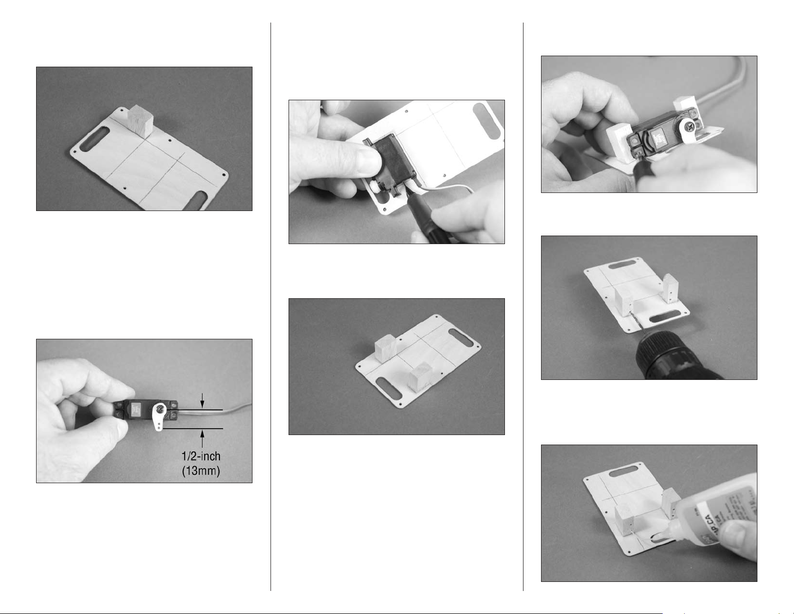
4. Use 30-minute epoxy to glue the 17mm x 12mm x
10mm hardwood block to the servo cover. Allow the epoxy
to fully cure before proceeding.
5. Repeat Steps 2 through 4 for the remaining servo
cover and block.
7. Position the aileron servo with the grommets resting
on the first mounting block and the servo parallel to the
line on the cover. Space the servo so it is not resting on the
servo cover as this will cause vibrations from the airframe to
be transferred to the servo. Use a pencil to mark the location
for the remaining servo mounting block.
9. Use a pencil to mark the locations for the four servo
mounting screws on the blocks.
10. Use a drill and 1/16-inch (1.5mm) drill bit to drill
the holes for the mounting screws.
6. Prepare the aileron servo by installing the rubber
grommets and brass eyelets as shown in the radio or servo
instructions. Center the aileron servo using the radio system.
Enlarge the hole in the servo arm using a pin vise and 5/64inch (2mm) drill bit that is 1/2-inch (13mm) from the center
of the servo horn. Use side cutters to remove any arms from
the horn that may interfere with the operation of the servo.
8. Use 30-minute epoxy to glue the remaining block
to the cover. Don’t forget to roughen the end of the block as
shown in Step 3.
11. Apply 2–3 drops of thin CA in each hole drilled.
Also saturate the top of the block using thin CA to harden the
block. This will keep the block from splitting when the servo
mounting screws are installed.
17Hangar 9 Jackal 50 ARF
Page 18
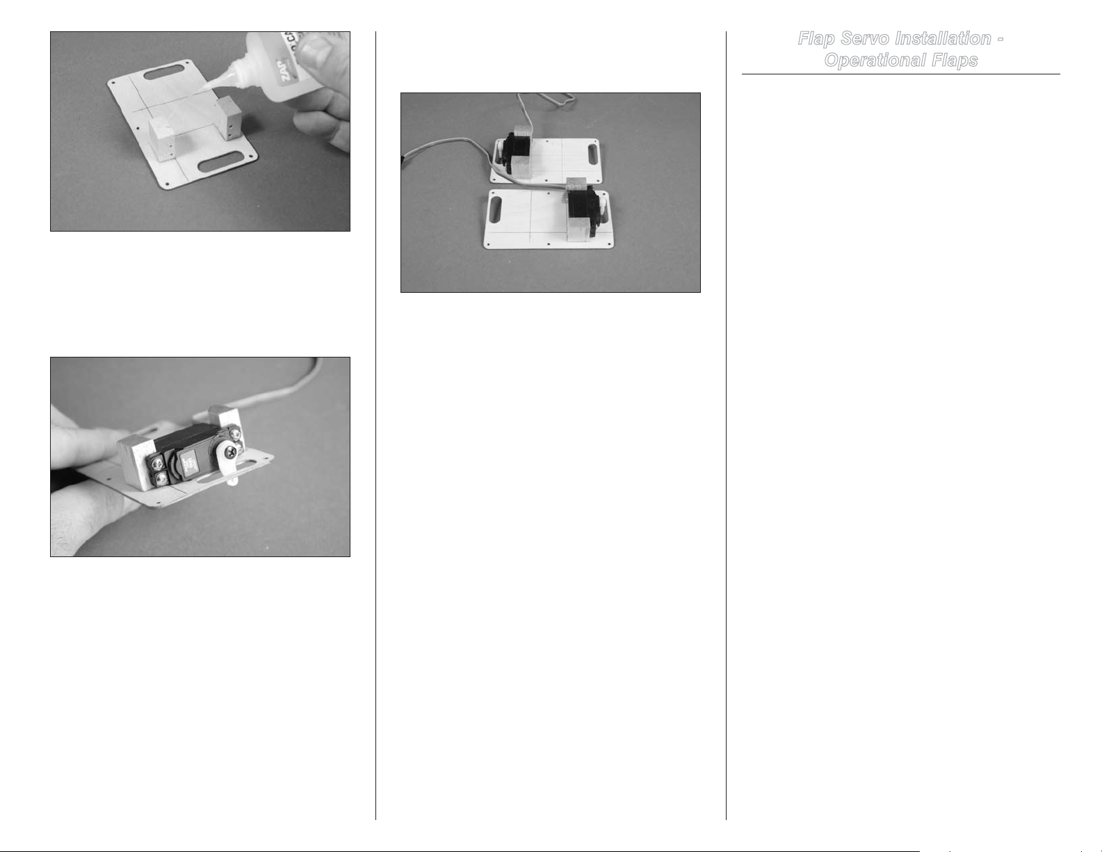
Important: Do not use a CA accelerator. Using an
accelerator will not allow the CA to soak into the fibers
of the wood, hardening the blocks.
12. Use the screws provided with the servo and a #1
Phillips screwdriver to attach the servo to the mounting blocks.
13. Repeat Steps 6 though 12 to install the remaining
aileron servo. Make sure you install the servo so you have a
right and left servo installation as shown in the photo.
Flap Servo Installation -
Operational Flaps
Required Parts
Servo cover with aileron servos (2)
Receiver Receiver battery
Servo with hardware (2) Transmitter
17mm x 12mm x 10mm servo mounting block (4)
Required Tools and Adhesives
Thin CA Low-tack tape
Mixing cup Medium grit sandpaper
30-minute epoxy Mixing stick
Pencil Side cutter
Pin vise Drill
Drill bit: 1/16-inch (1.5mm), 5/64-inch (2mm)
Note: If you are installing fixed flaps, please skip this
section and continue to “Flap Stay Installation,” the next
section of this manual.
Important: The flap servos cannot be operated using
a standard Y-harness. They will move in opposite
directions. The options for connecting the flaps to the
receiver are as follows:
Option 1: Use a computer radio to mix the flap
channel to an auxiliary channel. This will allow the
greatest versatility for the actuation of the flaps,
allowing the throws and endpoint to be set in the radio
programming.
Option 2: Use a JR MatchBox
to operate the flap servos. You will be able to set
the direction of the servos as well as the throws and
endpoints, matching the right and left flaps together.
Option 3: Use a reversing Y-harness. This will operate
the flaps, but they will not be able to be adjusted
individually. There may be a slight variation between the
endpoints and throws between the two servos, but they
will operate in unison as flaps.
Note: The installation of the flap servos follows the
same procedure as the aileron servos. The reference
lines should be drawn on the servo covers at this time.
18 Hangar 9 Jackal 50 ARF
™
from the flap channel
Page 19
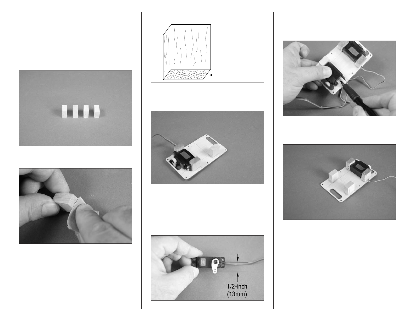
Hint: Place a piece of low-tack tape on the aileron
Sand this end
servo. The servo covers can fit in either the left or right
wing panel, but since the aileron servos are centered
using the radio, you will want to make sure the aileron
servos are oriented correctly in the wing when installed.
1. Locate hardwood blocks to mount the servos to the
covers. You will also need the servo covers with the aileron
servos installed.
2. Lightly sand the end of the block using medium grit
sandpaper. Sand the end grain as shown.
5. Position the flap servo with the grommets resting
on the first mounting block and the servo parallel to the
line on the cover. Use a pencil to mark the location for the
remaining servo mounting block.
3. Use 30-minute epoxy to glue the 17mm x 12mm x
10mm hardwood block to the servo cover. Allow the epoxy
to fully cure before proceeding.
6. Use 30-minute epoxy to glue the remaining block
to the cover. Don’t forget to roughen the end of the block as
shown in Step 3.
4. Prepare the flap servo by installing the rubber
grommets and brass eyelets as shown in the radio or servo
instructions. Center the flap servo using the radio system.
Enlarge the hole in the servo arm using a pin vise and 5/64inch (2mm) drill bit that is 1/2-inch (13mm) from the center
of the servo horn. Use side cutters to remove any arms from
the horn that may interfere with the operation of the servo.
19Hangar 9 Jackal 50 ARF
Page 20
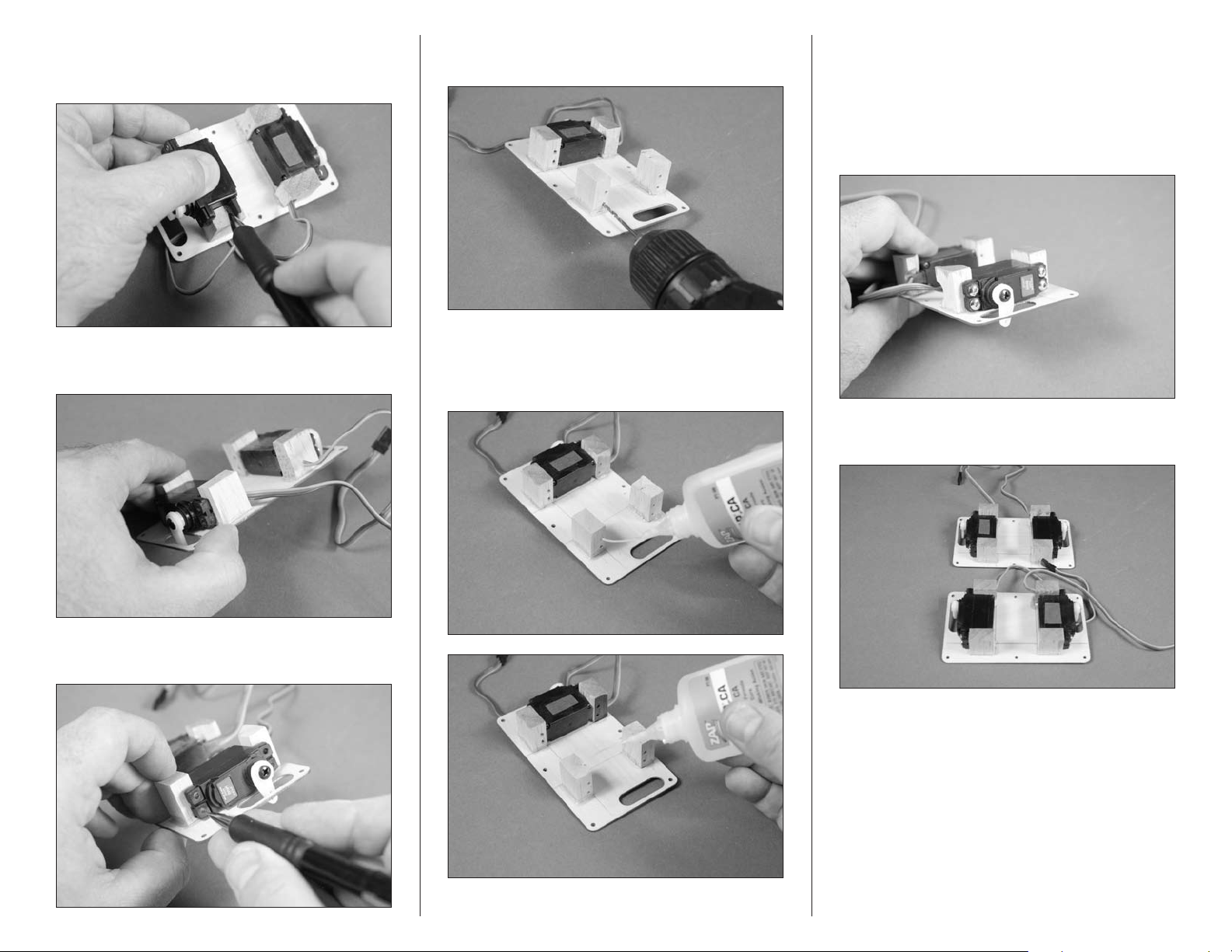
7. Position the servo on the blocks. Use a pencil to
mark the front block where it will need to be trimmed to
clear the servo lead.
8. Use a rotary tool and sanding drum to remove the
material from the block so the servo lead can clear the block.
10. Use a drill and 1/16-inch (1.5mm) drill bit to drill
the holes for the mounting screws.
11. Apply 2–3 drops of thin CA in each hole drilled.
Also saturate the top of the block using thin CA to harden the
block. This will keep the block from splitting when the servo
mounting screws are installed.
Important: Do not use a CA accelerator. Using an
accelerator will not allow the CA to soak into the fibers
of the wood, hardening the blocks.
12. Use the screws provided with the servo and
a #1 Phillips screwdriver to attach the servo to the
mounting blocks.
13. Repeat Steps 2 though 12 to install the remaining
flap servo.
9. Use a pencil to mark the locations for the four servo
mounting screws on the blocks.
20 Hangar 9 Jackal 50 ARF
Page 21
Flap Stay Installation - Fixed Flaps
Required Parts
Wing panel (right and left) Flap stay (right and left)
2mmx 15mm sheet metal screw (4)
Required Tools and Adhesives
Phillips screwdriver: #1
Required Tools and Adhesives (optional)
30-minute epoxy Mixing stick
Mixing cup Thin CA
Note: If you are installing operational flaps please skip
this section and continue to “Flap and Aileron Linkage
Installation” which is the next section of this manual.
Note: The flap stays installed in this section can be
removed if you choose to install operational flaps in the
future. They can also be installed permanently using
30-minute epoxy if you choose not to install operational
flaps during the life of your model. This will be covered
in this section of the manual.
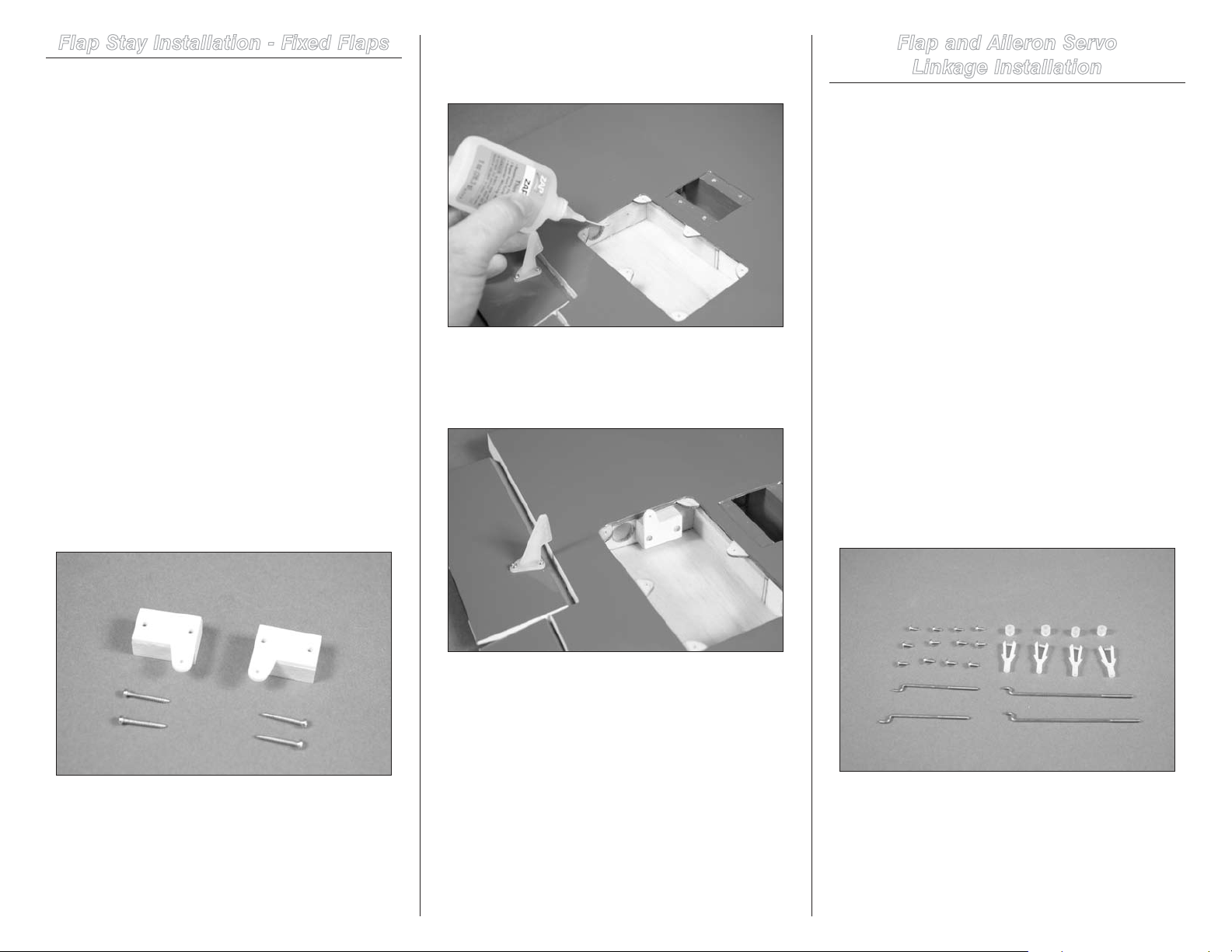
1. Locate the flap stays and hardware to install them
into the wing. You will also need the right and left wing
panels for this step.
2. Place 2–3 drops of thin CA in each of the flap stay
screw holes to harden the surrounding wood. This will help
in preventing the screws from vibrating loose.
3. Use the two 2mm x 15mm sheet metal screws to
secure the flap stay in the wing. Note the stay faces the
trailing edge of the wing and that the nylon portion of the
stay is placed more into the servo pocket as shown.
Flap and Aileron Servo
Linkage Installation
Required Parts
Wing panel (right and left)
Clevis (4) Silicone clevis keeper (4)
Servo cover assembly (right and left)
2-56 x 3-inch pushrod (aileron) (2)
2-56 x 2-inch pushrod (flap) (2)
1.5mm x 6mm sheet metal screw (12)
Required Tools and Adhesives
Phillips screwdriver: #1 Thin CA
Clear tape
Note: This section covers the installation of the
linkages for the flaps and ailerons. The installation of
the flap linkages for both fixed and operational flaps
follow the same procedure. Although the steps show
operational flaps, a final photo will show the fixed flap
linkage for reference.
1. Locate the items necessary to install the flap and
aileron linkages. You will also need the servo covers with
aileron (and flap) servos installed, as well as the right and
left wing panels.
4. Optional: If you choose to install the stay
permanently, use a small amount of 30-mionute epoxy on
the wood portion of the stay where it contacts the wing ribs.
This will secure the stay in the wing, making it impossible to
remove without damaging the wing.
5. Repeat Steps 2 and 4 to install the remaining flap stay.
21Hangar 9 Jackal 50 ARF
Page 22
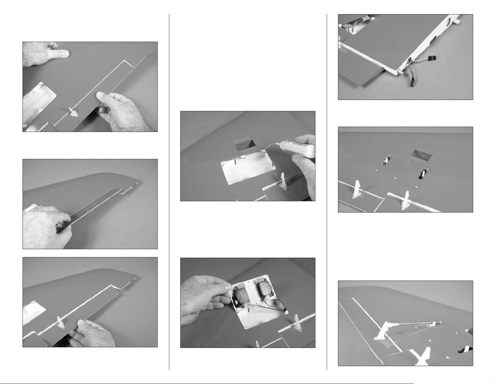
2. Check that all the hinges are secure by gently trying
to separate the aileron and flap from the wing. If any hinges
are loose, re-apply CA to the loose hinges.
3. Break in the hinges by working the aileron and flap
up and down a number of times.
4. At this time we recommend that you seal the hinge
gap between the wing and aileron. Use either clear covering
or tape to seal the gap to prevent flutter of the control
surfaces during high-speed flight.
5. Apply 2–3 drops of thin CA in each of the holes that
will accept the servo cover mounting screws.
Note: Read through the next few steps to make sure
the servo cover assemblies are installed correctly. The
servo output will be toward the leading edge of the
wing, with the aileron servo aligning with the aileron
control horn.
7. Use six 1.5mm x 6mm sheet metal screws and a #1
Phillips screwdriver to secure the cover to the wing.
6. Guide the leads from the aileron (and flap) servos
through the tube in the wing to the root.
Hint: Place a piece of low-tack tape on the end of the
aileron servo lead so it can be distinguished from the
flap servo lead before guiding them through the tube.
22 Hangar 9 Jackal 50 ARF
8. Attach the 2-56 x 3-inch pushrod wire to the aileron
servo horn using the Z-bend in the pushrod wire. Slide a
silicone clevis keeper on a clevis. Thread the clevis on the
pushrod wire. With the servo centered, attach the clevis to
the hole in the control horn that is three up from the control
surface. Make sure the aileron is centered when the clevis is
connected. Slide the silicone clevis keeper over the forks of
the clevis to keep it from opening accidentally in flight.
Page 23
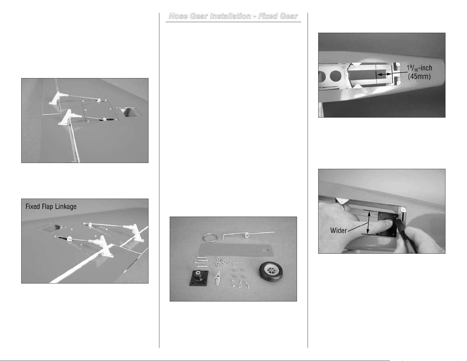
9. Attach the 2-56 x 2-inch pushrod wire to the flap
servo horn using the Z-bend in the pushrod wire. Slide a
silicone clevis keeper on a clevis. Thread the clevis on the
pushrod wire. With the servo centered, connect the clevis to
the hole in the control horn that is one hole away from the
control surface. Attach the clevis to the hole in the control
horn that is two up from the control surface. With the flap in
the up position, adjust the clevis so the flap is aligned with
the aileron.
Note: When fixed flaps are used, adjust the length of
the linkage to set the flap in the up position, aligned
with the aileron.
Nose Gear Installation - Fixed Gear
Required Parts
Fuselage Pull-pull fitting (2)
Landing gear base Nose gear wire strut
Fixed gear fuselage plate Steering arm with screw
#6 x 1/2-inch sheet metal screw (4)
4mm wheel collar with setscrew (3)
Nose wheel, 2
1.6mm x 6mm sheet metal screw (6)
Pull-pull cable, 42-inch (1070mm)
5/16-inch (8mm) copper crimp (4)
Required Tools and Adhesives
Phillips screwdriver: #1, #2 Drill
Drill bit: 3/32-inch (2.5mm) Pencil
Thin CA Threadlock
Flat file Light machine oil
Ruler Crimping tool or pliers
Side cutter Hex wrench: 1.5mm
Felt-tipped pen
Needle nose pliers or hemostats
1. Locate the items necessary to install the fixed nose
gear in the fuselage. You will also need the fuselage for
your model.
1
/4-inch (57mm)
2. Use a pencil to make a mark that is 1
from the back of the firewall on both mounting rails.
9
/16-inch (45mm)
3. Position the landing gear base on the rails. The base
is rectangular, and the wider portion of the base will straddle
the landing gear rails. Center the base on the rails, and align
the rear edge of the base with the line made in the previous
step. Use a pencil to transfer the location of the mounting
screws on the rails.
10. Repeat Steps 2 though 9 to install the
remaining linkages.
23Hangar 9 Jackal 50 ARF
Page 24
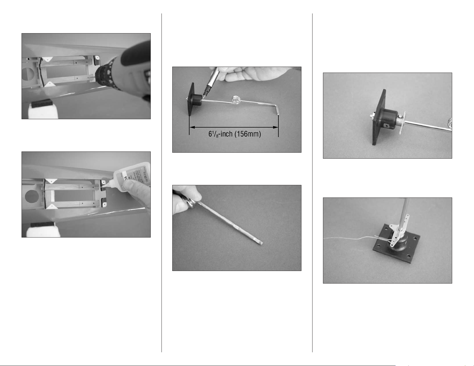
4. Use a drill and 3/32-inch (2.5mm) drill bit to drill the
four holes for the landing gear base mounting screws.
5. Place 2–3 drops of thin CA in each hole to harden the
surrounding wood. This will help prevent the screws from
pulling loose on hard landings.
6. Slide the nose gear strut into the landing gear block.
Place a 4mm wheel collar at the top of the block. Position
the collar so the distance between the top edge of the
block and centerline of the axle is 61/8-inch (156mm).
Tighten the collar so it leaves a mark on the wire. Use a
felt-tipped pen to mark the wire under the block for the
steering arm location.
8. Slide the steering arm on the nose gear strut, then the
landing gear base. The wheel collar can now be placed and
the setscrew tightened using a 1.5mm hex wrench. Check
the distance between the top edge of the base and axle as
shown in Step 6 and adjust as necessary. Slide the steering
arm against the base and use a #1 Phillips screwdriver to
tighten the screw. Make sure to use threadlock on both
screws to prevent them from vibrating loose.
7. Use a flat file to make two flat areas for the wheel
collar and steering arm setscrews. Make sure the flat areas
are parallel to the axle. Make each flat 1/4-inch (6mm) wide.
9. Pass the cable into a copper crimp. The wire then
goes through the center hole on the steering arm, then back
through the crimp. Use a crimping tool or pliers to secure
the wire.
Hint: If it is difficult to fit the wire through the crimp,
use pliers to slightly flatten the crimp to make it an oval
shape when viewed from the end.
24 Hangar 9 Jackal 50 ARF
Page 25
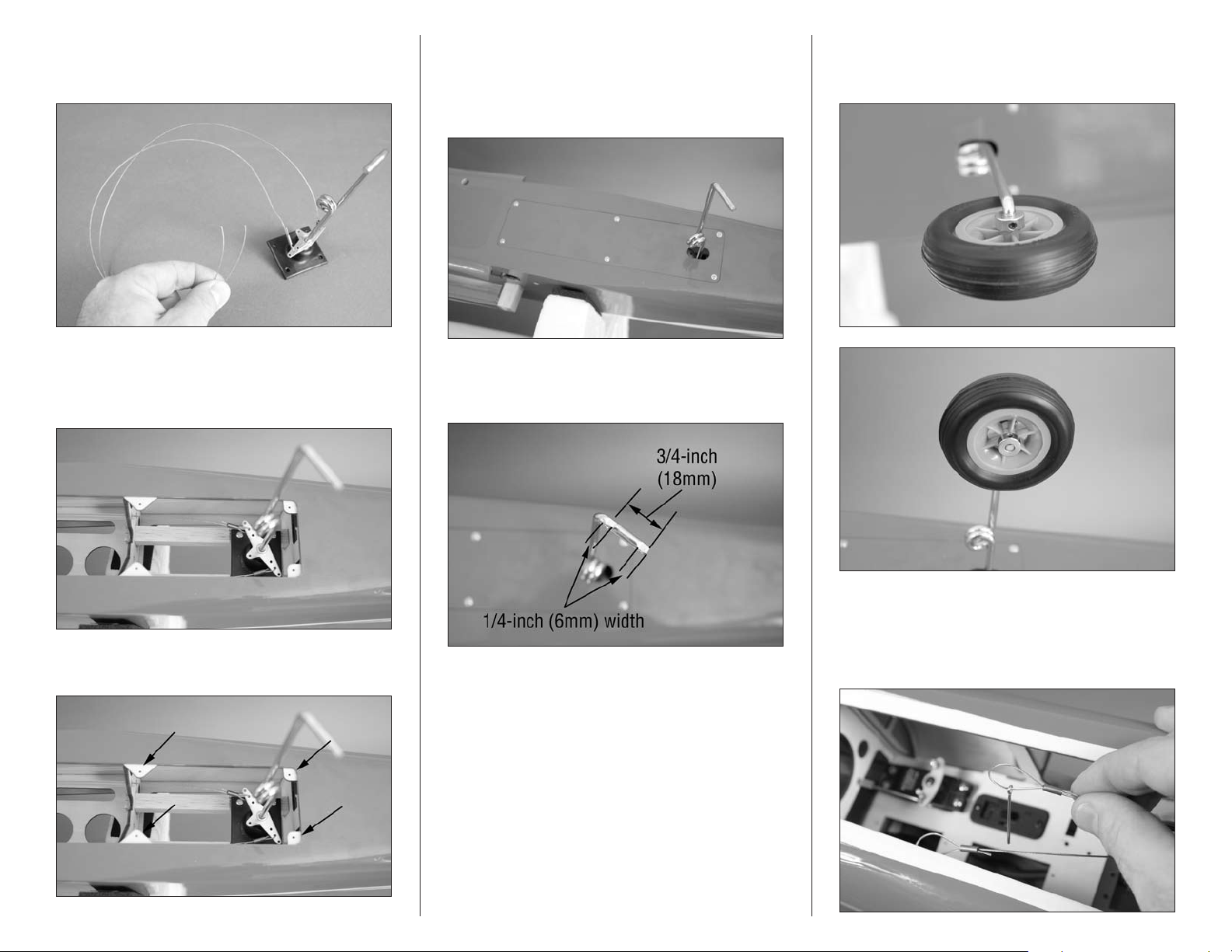
10. Secure the loose end of the cable to the steering arm
as described in Step 9. Use side cutters to cut the cable so
equal portions of the wire extend from the steering arm.
13. Use 2–3 drops of thin CA in each of the holes for the
screws to harden the surrounding wood. Use six 1.5mm x
6mm sheet metal screws to attach the fixed gear fuselage
plate to the fuselage. Use a #1 Phillips screwdriver to tighten
the screws.
15. Secure the wheel on the axle using two 4mm wheel
collars. Remember to place a drop of oil on the axle before
installing the wheel and to use threadlock on the setscrews.
11. Mount the nose gear assembly in the fuselage using
four #6 x 1-inch sheet metal screws. Tighten the screws
using a #2 Phillips screwdriver. Insert the steering cables
into their respective tubes in the fuselage.
12. Use 2–3 drops of thin CA in each of the holes for the
screws to harden the surrounding wood.
14. Use a flat file to make two 1/4-inch (6mm) wide flat
areas on the axle. The first is at the end of the axle, and the
second centered 3/4-inch (18mm) from the end of the axle.
16. Prepare the cables to connect to the rudder servo
by sliding a copper crimp on the wire, then a pull-pull
fitting. The cable then goes back through the copper crimp.
DO NOT crimp the cable, as it must be adjusted before
securing the crimps.
25Hangar 9 Jackal 50 ARF
Page 26
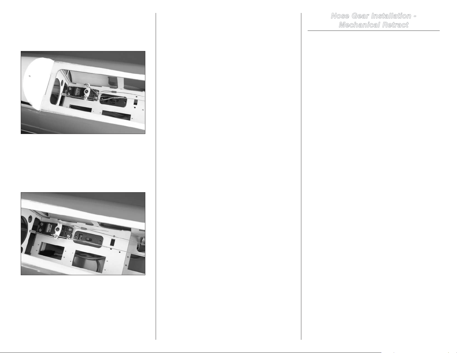
17. Insert the pull-pull fittings in the brass pushrod
connectors. With the end of the pull-pull fitting extending
1/4-inch (6mm) through the connector, use a #1 Phillips
screwdriver to lightly tighten the screw in the connector to
hold the fitting in place.
18. Adjust the cables so there is light and equal tension
on both cables. Check to make sure that when the rudder
servo is centered, the nose wheel is parallel to the fuselage
center line.
Hint: Use needle nose pliers or hemostats to tension
the cables.
19. Slide the crimp as close to the pull-pull fitting as
possible. This will keep the setting on the cables. Carefully
remove the fittings from the pushrod connector and use
crimping pliers to secure the position of the crimps. Trim any
excess cable using side cutters. Place the fittings back in the
connector and tighten the screw in the connector to secure
the fittings. Use threadlock on the screw to prevent it from
vibrating loose.
Important: It may be necessary to check the tension
of the cables periodically as they can stretch over
time. Also use the connectors and fittings to adjust the
steering if you find your model does not taxi straight
down the runway.
Nose Gear Installation -
Mechanical Retract
Required Parts
Fuselage Nose gear retract
2-56 nut Retract gear fuselage plate
Pull-pull fitting (2) Retract servo (2)
Axle Axle keeper
Nylon axle spacer Heavy-duty servo arm (2)
Y-harness Transmitter
2-56 ball links (not included)
#6 x 12-inch sheet metal screw (4)
Nose wheel, 2
11mm x 7mm x 48mm hardwood block (2)
1.6mm x 6mm sheet metal screw (6)
2-56 x 15
Pull-pull cable, 42-inch (1070mm)
5/16-inch (8mm) copper crimp (4)
5
8
/8-inch (218mm) pushrod tube
Required Tools and Adhesives
Felt-tipped pen Medium CA
Side cutters Mixing sticks
Clamps Epoxy brush
Phillips screwdriver: #1, #2 Drill
Thin CA Threadlock
Flat file Light machine oil
Ruler Crimping tool or pliers
Mixing cup 30-minute epoxy
Rotary tool with cutoff wheel Side cutter
Pencil Denatured alcohol
Hex wrench or ball driver: 5/64-inch
Drill bit: 3/32-inch (2.5mm), 3/16-inch (5mm)
Needle nose pliers or hemostats
1
/4-inch (57mm)
1
/4-inch pushrod wire, threaded both ends
Important: Before installing the nose gear retract, it
is recommended to use a fuel-proof paint or thinned
epoxy(mix20%denaturedalcoholto80%epoxy)
to seal all the wood inside the opening for the nose
gear. This will protect the wood and extend the life of
your model.
26 Hangar 9 Jackal 50 ARF
Page 27
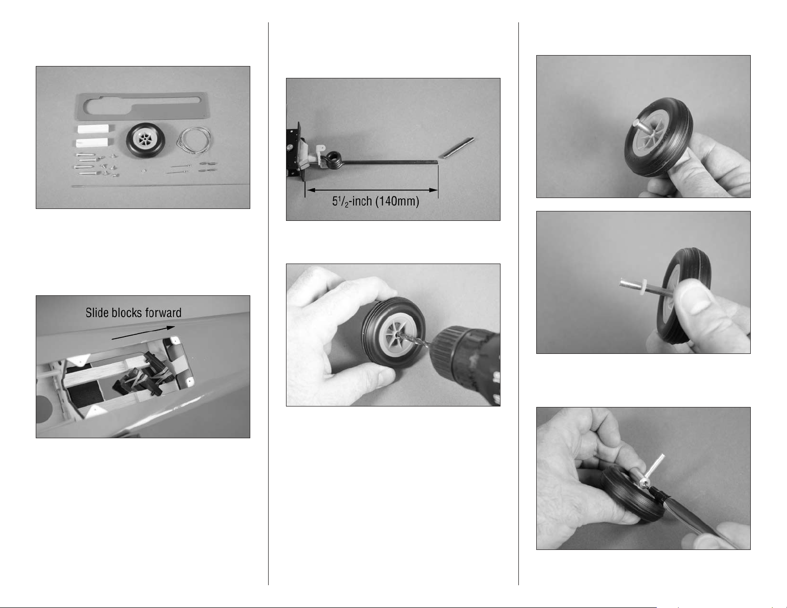
1. Locate the items necessary to install the mechanical
retract nose gear in the fuselage. You will also need the
fuselage for your model.
2. Use 30-minute epoxy to glue the two 11mm x 7mm x
48mm hardwood blocks to the landing gear rails. The wider
11mm measurement will match the width of the landing gear
rails in the fuselage. Slide the blocks forward on the rails
so they fit tightly against the back of the former. Use small
clamps to hold them in position until the epoxy fully cures.
3. Use a rotary tool and cutoff wheel to cut the length of
the nose gear strut to 51/2-inch (140mm) as shown in the
photo below. Measure from the bottom edge of the mounting
flange of the retract housing.
4. Use a drill and 3/16-inch (5mm) drill bit to enlarge the
hole in the wheel.
5. Slide the axle through the hole in the wheel. Slide a
nylon spacer on the axle from the opposite side.
Note: We recommend the use of a drill press to enlarge
the hole in the wheel so it is straight.
6. Slide the adapter on the axle. Use a felt-tipped pen
to mark the location for the setscrew and the outside edge
where the axle will need trimmed.
27Hangar 9 Jackal 50 ARF
Page 28
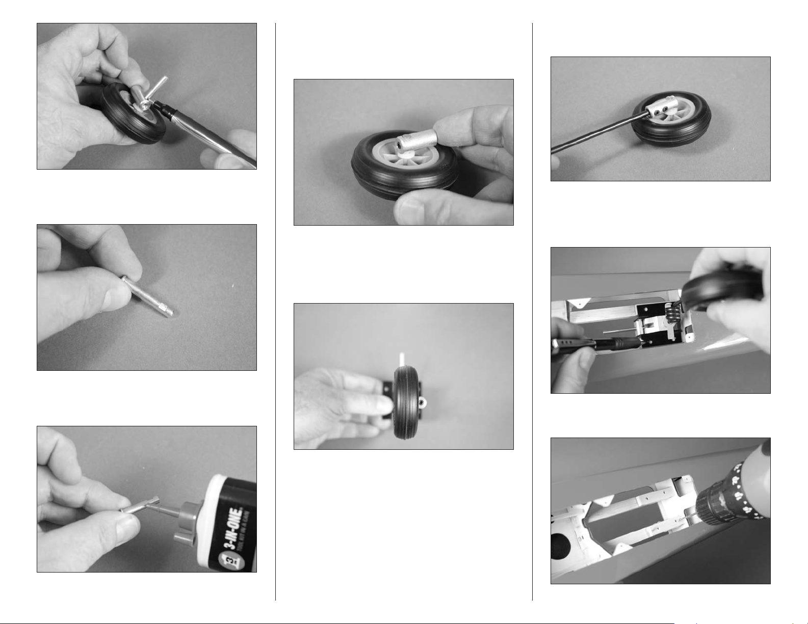
7. Use a rotary tool and cutoff wheel to trim the length of
the axle. Use a flat file to make a 1/4-inch (6mm) wide flat
where the setscrew from the adapter will rest.
9. Assemble the nose wheel assembly as shown. Use
threadlock on the setscrew before using a 5/64-inch hex
wrench or ball driver to tighten the setscrew on the flat area
made in the previous step.
10. Before attaching the nose wheel assembly to the nose
gear wire, use a flat file to make flats for the setscrews on
the nose gear wire for the adapter. Make sure the nose wheel
is aligned with the retract actuator when the steering arm is
perpendicular to the actuator.
11. Use the setscrews included with your retracts and
threadlock to secure the adapter to the nose gear wire.
12. Position the retract mechanism on the rails. Center
the mechanism on the rails, and align the rear edge of the
mechanism with end of the hardwood blocks. Use a pencil to
transfer the location of the mounting screws on the rails.
8. Place a drop of light machine oil on the axle before
sliding it into the wheel so it rolls smoothly during takeoff
and landing.
28 Hangar 9 Jackal 50 ARF
13. Use a drill and 3/32-inch (2.5mm) drill bit to drill the
four holes for the landing gear base mounting screws.
Page 29
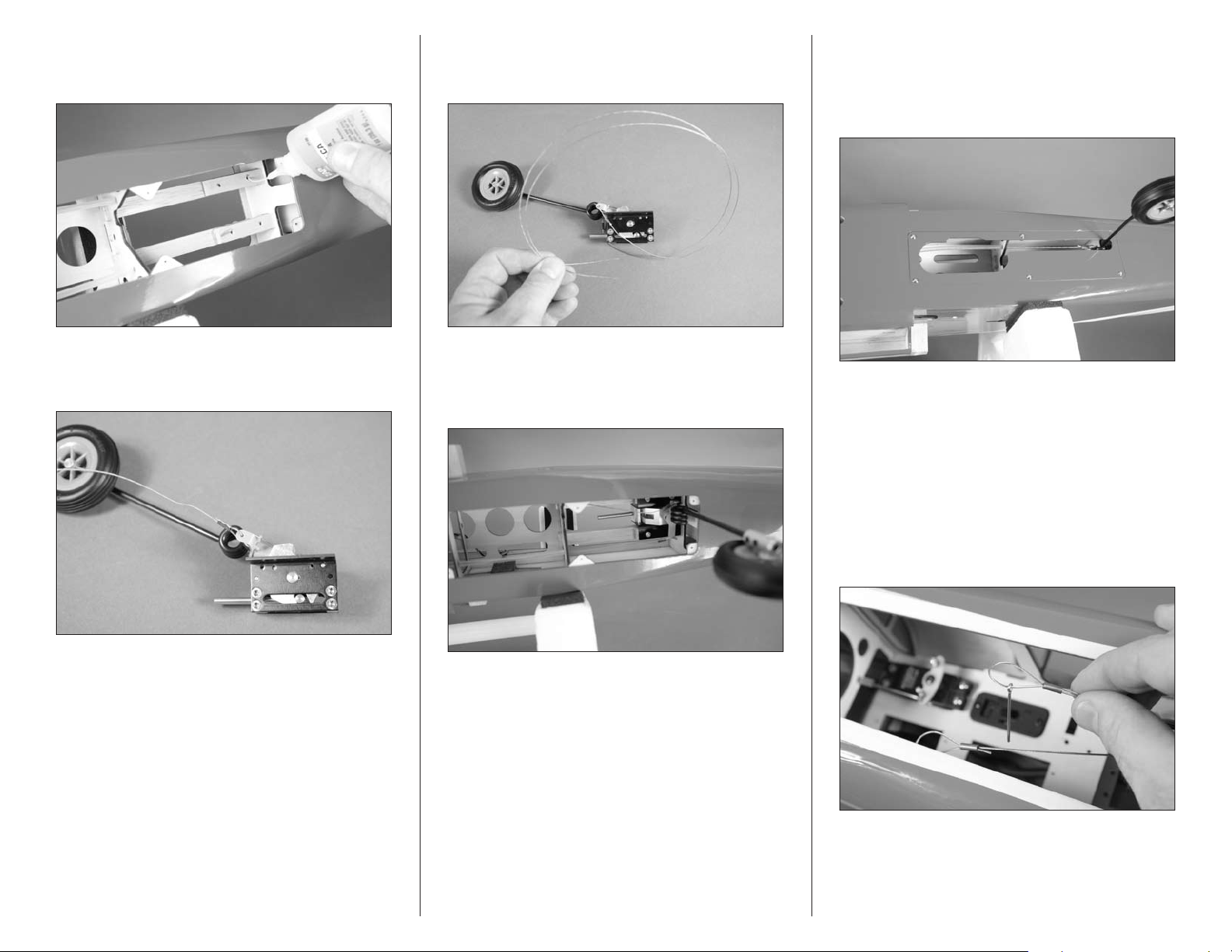
14. Place 2–3 drops of thin CA in each hole to harden the
surrounding wood. This will help prevent the screws from
pulling loose on hard landings.
16. Secure the loose end of the cable to the steering arm
as described in Step 13. Use side cutters to cut the cable so
equal portions of the wire extend from the steering arm.
18. Use 2–3 drops of thin CA in each of the holes for the
screws to harden the surrounding wood. Use six 1.5mm x
6mm sheet metal screws to attach the retract gear fuselage
plate to the fuselage. Use a #1 Phillips screwdriver to tighten
the screws.
15. Pass the cable into a copper crimp. The wire then
goes through the hole in the steering arm, then back through
the crimp. Use a crimping tool or pliers to secure the wire.
Hint: If it is difficult to fit the wire through the crimp,
use pliers to slightly flatten the crimp to make it an oval
shape when viewed from the end.
17. Mount the nose gear assembly in the fuselage using
four #6 x 1-inch sheet metal screws. Tighten the screws
using a #2 Phillips screwdriver. Insert the steering cables
into their respective tubes in the fuselage.
Important: Make sure the nose gear is in the down
and locked position before connecting the cables to the
rudder servo. If the gear is up, the cables will not be
installed correctly and your nose gear retract will not
operate properly.
19. Prepare the cables to connect to the rudder servo
by sliding a copper crimp on the wire, then a pull-pull
fitting. The cable then goes back through the copper crimp.
DO NOT crimp the cable, as it must be adjusted before
securing the crimps.
29Hangar 9 Jackal 50 ARF
Page 30
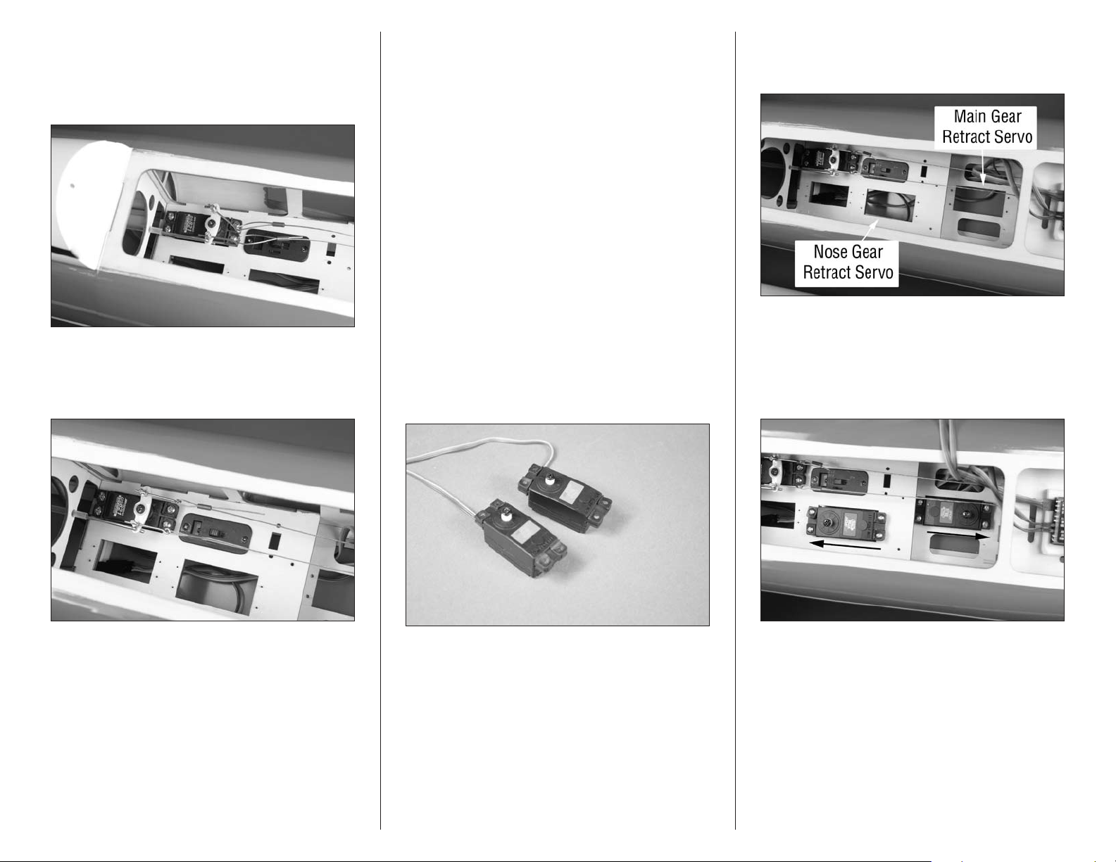
20. Insert the pull-pull fittings in the brass pushrod
connectors. With the end of the pull-pull fitting extending
1/4-inch (6mm) through the connector, use a #1 Phillips
screwdriver to lightly tighten the screw in the connector to
hold the fitting in place.
21. Adjust the cables so there is light and equal tension
on both cables. Check to make sure that when the rudder
servo is centered, the nose wheel is parallel to the fuselage
center line.
22. Slide the crimp as close to the pull-pull fitting as
possible. This will keep the setting on the cables. Carefully
remove the fittings from the pushrod connector and use
crimping pliers to secure the position of the crimps. Trim any
excess cable using side cutters. Place the fittings back in the
connector and tighten the screw in the connector to secure
the fittings. Use threadlock on the screw to prevent it from
vibrating loose.
Important: It may be necessary to check the tension
of the cables periodically as they can stretch over
time. Also use the connectors and fittings to adjust the
steering if you find your model does not taxi straight
down the runway.
Note: Although the retracts for the wing will not be
installed until later in the manual, we will be installing
the main gear retract servo at this time. Once the nose
gear and throttle linkages are installed, the installation
of the main gear retract servo will be difficult.
23. Prepare the two retract servos using the grommets
and brass eyelets. Remove the horns from the servos at
this time.
24. Apply 2–3 drops of thin CA in the holes for the main
gear and nose gear retract servo mounting screws. This
hardens the wood so the screws don’t vibrate loose.
25. Mount the retract servos in the fuselage using
the screws provided with the servos. Use a #1 Phillips
screwdriver to tighten the screws. The output for the nose
gear retract faces the rear of the fuselage, while the output
for the main gear retract servo faces to the front of the
fuselage.
Hint: Use needle nose pliers or hemostats to tension
the cables.
30 Hangar 9 Jackal 50 ARF
26. Plug the retract servos into a Y-harness. The Y-harness
is then plugged into the gear channel of the receiver.
Page 31
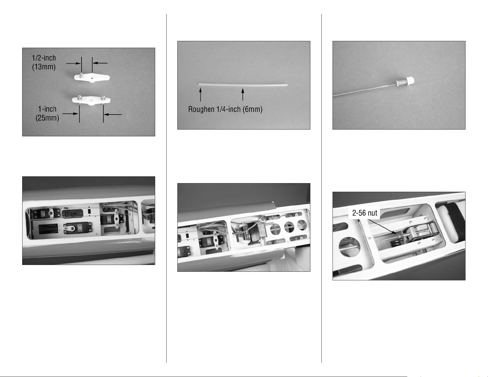
27. Prepare the main gear and nose gear servo arms.
Install the ball ends so they are 1-inch (25mm) apart as
shown. The nose gear servo arm uses only one ball link, but
it is positioned the same as the main gear.
29. Locate the 8
the first 1/2-inch (12mm) at the end and also a 1/2-inch
(12mm) section at the center of the tube.
5
/8-inch (217mm) pushrod tube. Roughen
31. Thread the ball end on the 2-56 x 15
wire. Start by setting it at around 12 to 14 turns on the wire.
Its final position will be adjusted once the pushrod is installed.
1
/4-inch pushrod
28. Install the servo arms on the retract servos as shown.
The nose gear is shown in the down position. Make sure the
switch on the radio is also in the position you will want as
the down setting.
30. Slide the pushrod tube in the fuselage with the end
that was not sanded toward the nose gear. Center the tube
and use medium CA to glue the tube to the center former
and the former near the servo compartment. Do not glue
the tube near the nose gear as it must be able to move to
operate properly.
32. Insert the pushrod wire into the pushrod tube. Once
the threads are exposed near the nose gear, thread a 2-56
nut on the threads as shown. The pushrod can then be
threaded into the actuator for the nose gear.
Hint: It is easier to thread the pushrod wire into the
actuator when the nose gear is in the up position.
33. It’s now time to set the length of the retract linkage.
With the nose gear in the down and locked position, use the
radio to move the servo to the down position. Adjust the
length of the linkage so the ball end fits on the ball without
any binding. Use the radio to move the retract servo to the
up position. Check that the retract is in up and locked. You
may need to fine-tune the length of the linkage to allow it to
move from up to down, locking the retract in both positions.
31Hangar 9 Jackal 50 ARF
Page 32
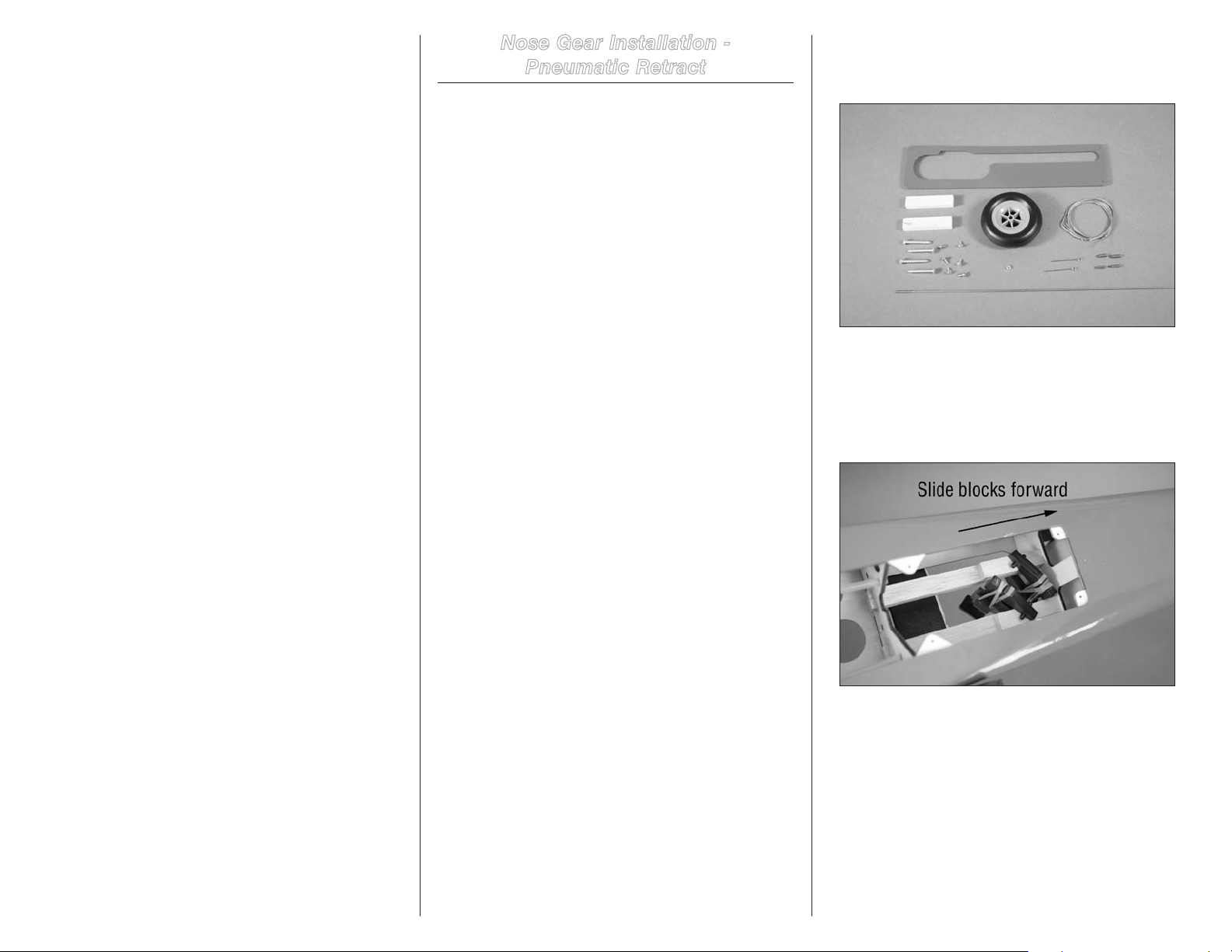
34. Use the radio to cycle the gear a number of times,
checking that the length of the linkage is correct. Although
it is important the gear locks in both the up and down
positions, it is most critical it is fully locked when down or
it may collapse on the runway during takeoff or landing.
Also make sure the servo is not binding at either position,
as this will quickly drain the receiver battery. Take your
time to set the linkage perfectly. Once complete, tighten
the 2-56 nut against the retract actuator to prevent it from
changing position.
Nose Gear Installation -
Pneumatic Retract
Required Parts
Fuselage Nose gear retract
Axle adapter Steel axle
Nylon spacer 2-56 nut
Retract gear fuselage plate Pull-pull fitting (2)
Retract servo
#6 x 12-inch sheet metal screw (4)
Nose wheel, 2
11mm x 7mm x 48mm hardwood block (2)
1.6mm x 6mm sheet metal screw (6)
Pull-pull cable, 42-inch (1070mm
5/16-inch (8mm) copper crimp (4)
Required Tools and Adhesives
Phillips screwdriver: #1, #2 Drill
Drill bit: 3/32-inch (2.5mm) Pencil
Thin CA Threadlock
Flat file Light machine oil
Ruler Crimping tool
Rotary tool with cutoff wheel Side cutter
30-minute epoxy Felt-tipped pen
Mixing cup Clamps
Mixing stick Epoxy brush
Denatured alcohol
Needle nose pliers or hemostats
1
/4-inch (57mm)
1. Locate the items necessary to install the pneumatic
retract nose gear in the fuselage. You will also need the
fuselage for your model.
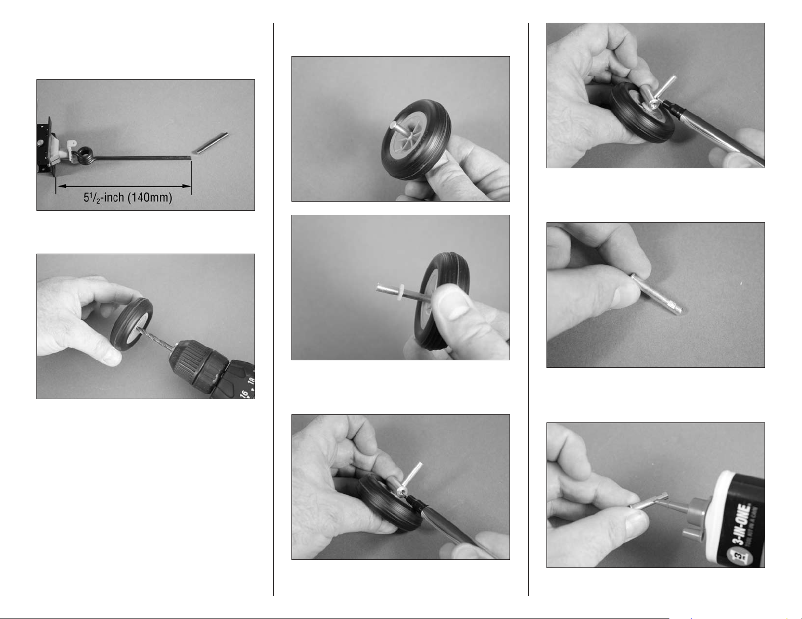
2. Use 30-minute epoxy to glue the two 11mm x 7mm x
48mm hardwood blocks to the landing gear rails. The wider
11mm measurement will match the width of the landing gear
rails in the fuselage. Slide the blocks forward on the rails
so they fit tightly against the back of the former. Use small
clamps to hold them in position until the epoxy fully cures.
Important: Before installing the nose gear retract, it
is recommended to use a fuel-proof paint or thinned
epoxy(mix20%denaturedalcoholto80%epoxy)
to seal all the wood inside the opening for the nose
gear. This will protect the wood and extend the life of
your model.
32 Hangar 9 Jackal 50 ARF
Page 33
3. Use a rotary tool and cutoff wheel to cut the length of
the nose gear strut to 51/2-inch (140mm) as shown in the
photo below. Measure from the bottom edge of the mounting
flange of the retract housing.
4. Use a drill and 3/16-inch (5mm) drill bit to enlarge the
hole in the wheel.
5. Slide the axle through the hole in the wheel. Slide a
nylon spacer on the axle from the opposite side.
7. Use a rotary tool and cutoff wheel to trim the length of
the axle. Use a flat file to make a 1/4-inch (6mm) wide flat
where the setscrew from the adapter will rest.
Note: We recommend the use of a drill press to enlarge
the hole in the wheel so it is straight.
6. Slide the adapter on the axle. Use a felt-tipped pen
to mark the location for the setscrew and the outside edge
where the axle will need trimmed.
8. Place a drop of light machine oil on the axle before
sliding it into the wheel so it rolls smoothly during takeoff
and landing.
33Hangar 9 Jackal 50 ARF
Page 34
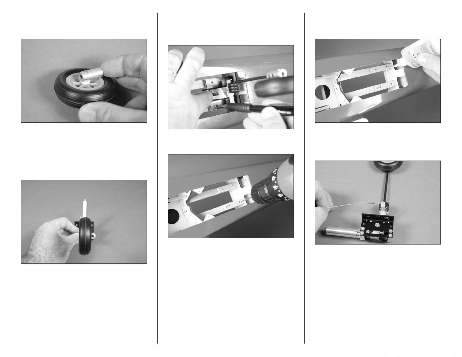
9. Assemble the nose wheel assembly as shown. Use
threadlock on the setscrew before tightening it on the flat
area made in the previous step.
11. Position the retract mechanism on the rails. Center
the mechanism on the rails, and align the rear edge of the
mechanism with end of the hardwood blocks. Use a pencil to
transfer the location of the mounting screws on the rails.
13. Place 2–3 drops of thin CA in each hole to harden the
surrounding wood. This will help prevent the screws from
pulling loose on hard landings.
10. Before attaching the nose wheel assembly to the
nose gear wire, use a flat file to make flats for the setscrews
on the nose gear wire for the adapter. Use the setscrews
included with your retracts and threadlock to secure the
adapter to the nose gear wire. Make sure the nose wheel is
aligned with the retract air cylinder when the steering arm is
perpendicular to the actuator.
12. Use a drill and 3/32-inch (2.5mm) drill bit to drill the
four holes for the landing gear base mounting screws.
14. Pass the cable into a copper crimp. The wire then
goes through the hole in the steering arm, then back through
the crimp. Use a crimping tool to secure the wire. Secure
each end to the steering arm at this time.
Hint: If it is difficult to fit the wire through the crimp,
use pliers to slightly flatten the crimp to make it an oval
shape when viewed from the end.
34 Hangar 9 Jackal 50 ARF
Page 35
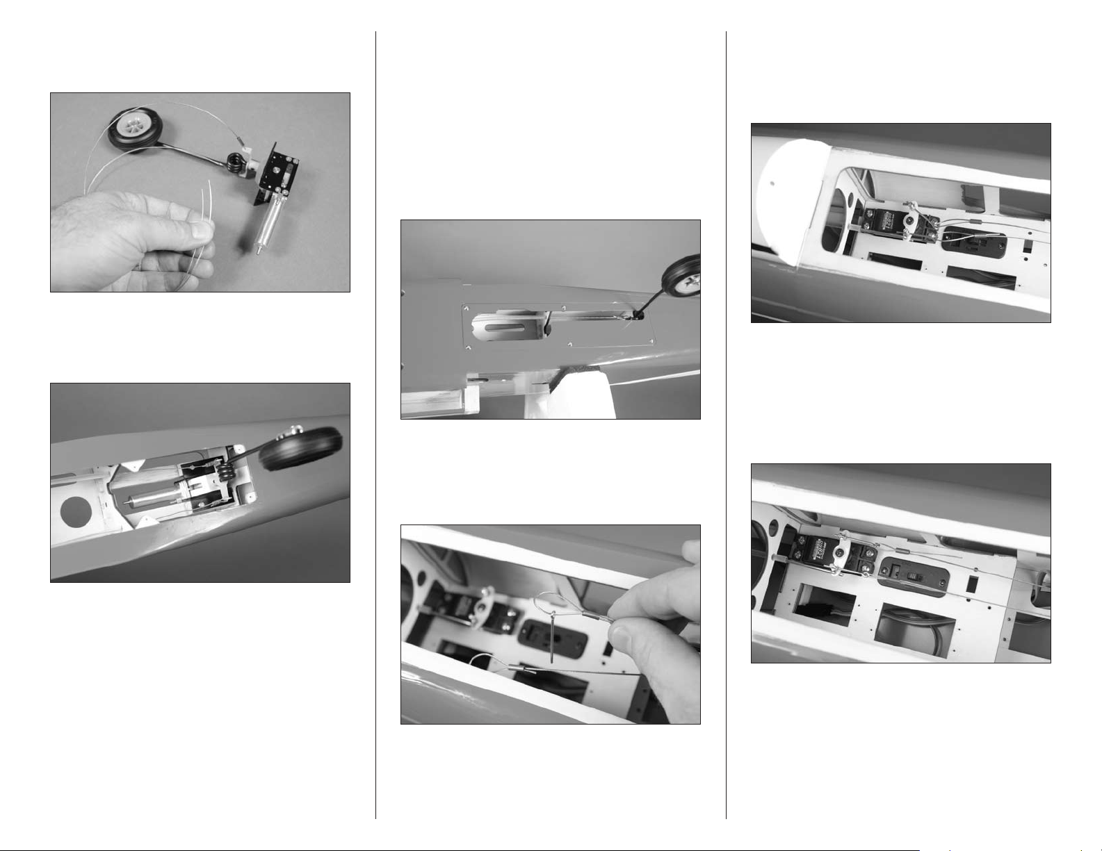
15. Secure the loose end of the cable to the steering arm
as described in Step 13. Use side cutters to cut the cable so
equal portions of the wire extend from the steering arm.
16. Mount the nose gear assembly in the fuselage using
four #6 x 1-inch sheet metal screws. Tighten the screws
using a #2 Phillips screwdriver. Insert the steering cables
into their respective tubes in the fuselage.
17. Use 2–3 drops of thin CA in each of the holes for the
screws to harden the surrounding wood. Use six 1.5mm x
6mm sheet metal screws to attach the retract gear fuselage
plate to the fuselage. Use a #1 Phillips screwdriver to tighten
the screws.
Important: Make sure the nose gear is in the down
and locked position before connecting the cables to the
rudder servo. If the gear is up, the cables will not be
installed correctly and your nose gear retract will not
operate properly.
18. Prepare the cables to connect to the rudder servo by
sliding a copper crimp on the wire, then a pull-pull fitting.
The cable then goes back through the copper crimp. DO NOT
crimp the cable, as it must be adjusted before securing the
crimps.
19. Insert the pull-pull fittings in the brass pushrod
connectors. With the end of the pull-pull fitting extending
1/4-inch (6mm) through the connector, use a #1 Phillips
screwdriver to lightly tighten the screw in the connector to
hold the fitting in place.
20. Adjust the cables so there is light and equal tension
on both cables. Check to make sure that when the rudder
servo is centered, the nose wheel is parallel to the fuselage
center line.
Hint: Use needle nose pliers or hemostats to tension
the cables.
35Hangar 9 Jackal 50 ARF
Page 36
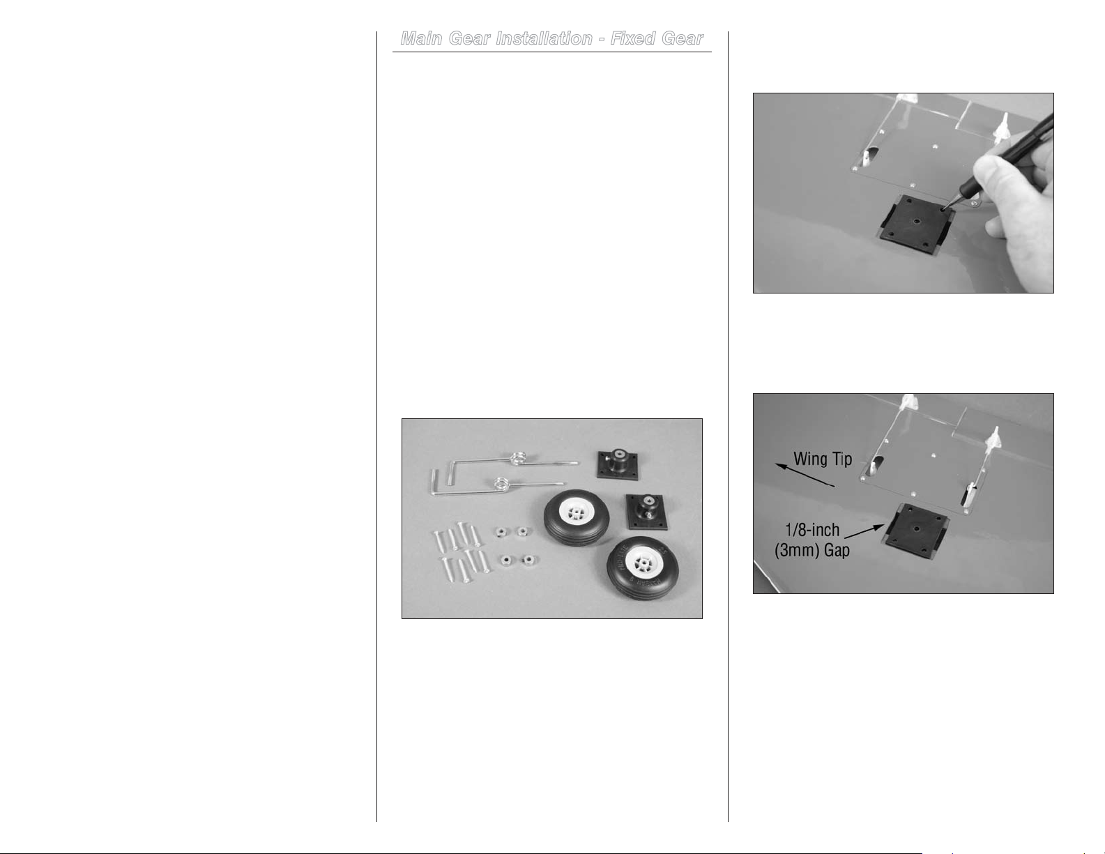
21. Slide the crimp as close to the pull-pull fitting as
possible. This will keep the setting on the cables. Carefully
remove the fittings from the pushrod connector and use
crimping pliers to secure the position of the crimps. Trim any
excess cable using side cutters. Place the fittings back in the
connector and tighten the screw in the connector to secure
the fittings. Use threadlock on the screw to prevent it from
vibrating loose.
Important: It may be necessary to check the tension
of the cables periodically as they can stretch over
time. Also use the connectors and fittings to adjust the
steering if you find your model does not taxi straight
down the runway.
Main Gear Installation - Fixed Gear
Required Parts
Wing panel (right and left)
Landing gear base with setscrew (2)
Main wheel, 2
4mm wheel collar with setscrew (4)
Main gear strut (right and left)
#6 x 1-inch sheet metal screw (8)
Required Tools and Adhesives
Phillips screwdriver: #2 Drill
Drill bit: 3/32-inch (2.5mm) Pencil
Thin CA Threadlock
Flat file Light machine oil
Hobby knife with #11 blade Ruler
Hex wrench: 1.5mm
1. Locate the items necessary to install the main fixed
gear in the wing panels. You will also need the right and left
wing panels from your model.
1
/2-inch (63.5mm) (2)
2. Place the landing gear base in the wing. Use a
pencil to transfer the mounting locations for the base on the
landing gear rails.
Important: If you plan on installing the recommended
retracts in the future, set the base so there is a 1/8-inch
(3mm) gap between the base and edge of the opening
near the wing tip as shown.
36 Hangar 9 Jackal 50 ARF
Page 37
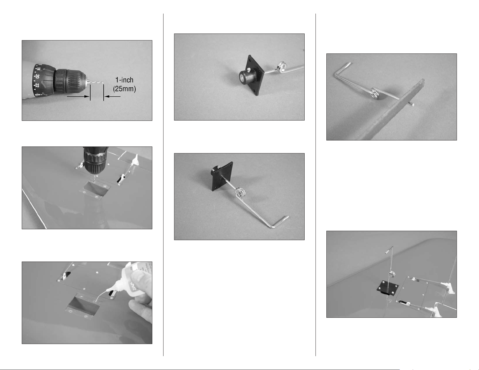
3. Place the 3/32-inch (2.5mm) drill bit in the drill. Set
the drill so it is 1-inch (25mm) from the chuck to prevent
accidentally drilling through the top of the wing.
6. Slide the main gear into the landing gear base. The
top of the gear will be flush with the top of the base.
8. Use a #2 Phillips screwdriver to tighten the screw
in the base on the wire. This will leave a mark on the wire
where you will need to file a flat area for the screw. This will
prevent the gear from rotating during takeoff and landing.
Use a flat file to make the flat on the wire.
4. Drill the four mounting holes for the landing gear
base using the drill and drill bit prepared in the previous step.
5. Place 2–3 drops of thin CA in each hole to harden
the surrounding wood. This makes it difficult for the screw
to pull loose on hard landings.
7. Place the gear and base on a flat surface. The wheel
axle will rest flat on the surface when the base is resting flat.
This will position the wheel straight forward when installed.
9. Once the flat is on the main gear wire, insert it back
into the base and tighten the screw. Check the alignment to
make sure the flat is in the correct location. Once complete,
use threadlock on the screw and tighten it to secure the
landing gear wire.
10. Place the block in the wing. Check that the spring
faces the rear and the wire for the wheel faces the wing
root. If not, you will need to prepare the opposite landing
gear wire for this particular wing panel. Use four #6 x 1-inch
sheet metal screws and a #2 Phillips screwdriver to secure
the landing gear block in the wing.
37Hangar 9 Jackal 50 ARF
Page 38
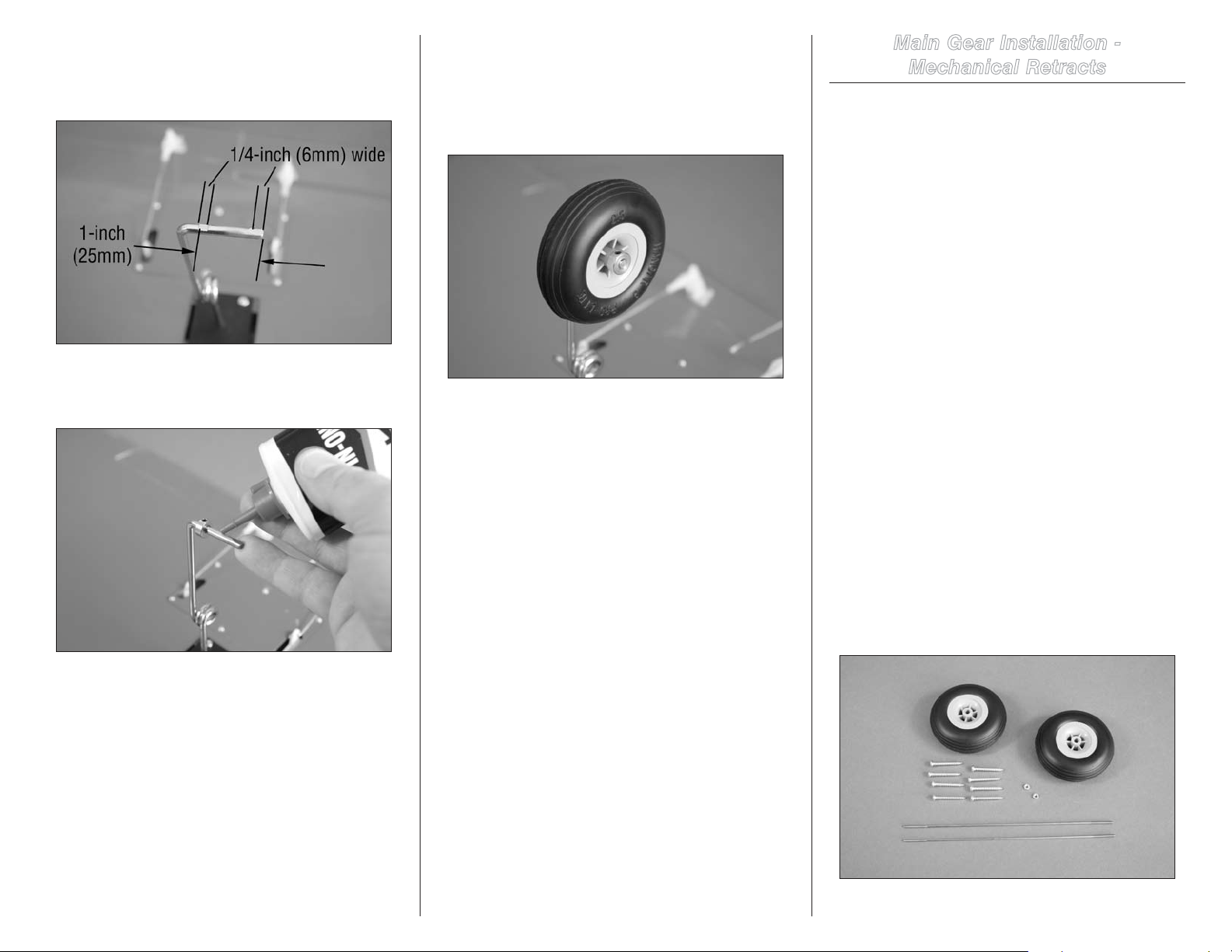
11. Use a flat file to make two flat areas on the wire
for the wheel. The first will cover the first 1/4-inch (6mm) of
the wire at the end, the other will be 1/4-inch (6mm) wide,
centered 1-inch (25mm) from the end of the wire.
13. Slide the wheel on the axle. Use a second 4mm
wheel collar to secure the wheel. Apply threadlock on the
setscrews and use a 1.5mm hex wrench to tighten the
setscrews on the flat areas made in Step 11. Check to make
sure the wheel rolls freely. If not, reposition the collars so
they are not causing binding.
Main Gear Installation -
Mechanical Retracts
Required Parts
Wing panel (right and left) Main gear retracts
Nylon washer (2) Axle adapter (2)
Axle (2) Transmitter
#4 washer (2) 2-56 nut (2)
Fuselage assembly Aluminum wing tube
2-56 ball link (2) (not included)
4-40 x 1-inch socket head screw (2)
Main wheel, 2.5-inch (63.5mm) (2)
2-56 x 6
#6 x 1-inch sheet metal screw (8)
1
/2-inch pushrod, threaded both ends (2)
12. Place the first 4mm wheel collar on the wire. Apply
2–3 drops of light machine oil to the axle so the wheel will
roll freely when installed.
14. Repeat Steps 2 through 13 to prepare and install the
remaining main landing gear.
Required Tools and Adhesives
Rotary tool Cutoff wheel
Hobby knife with #11 blade Covering iron
Sealing iron Ruler
Felt-tipped pen
Phillips screwdriver: #2 Drill
Pencil Thin CA
Threadlock Flat file
Light machine oil Hex wrench: 5/64-inch
Drill bit: 3/32-inch (2.5mm), 3/16-inch (5mm)
1. Locate the items necessary to install the main
mechanical retracts in the wing panels. You will also need
the right and left wing panels from your model as well as the
retract mechanism and axles for both wing panels.
38 Hangar 9 Jackal 50 ARF
Page 39
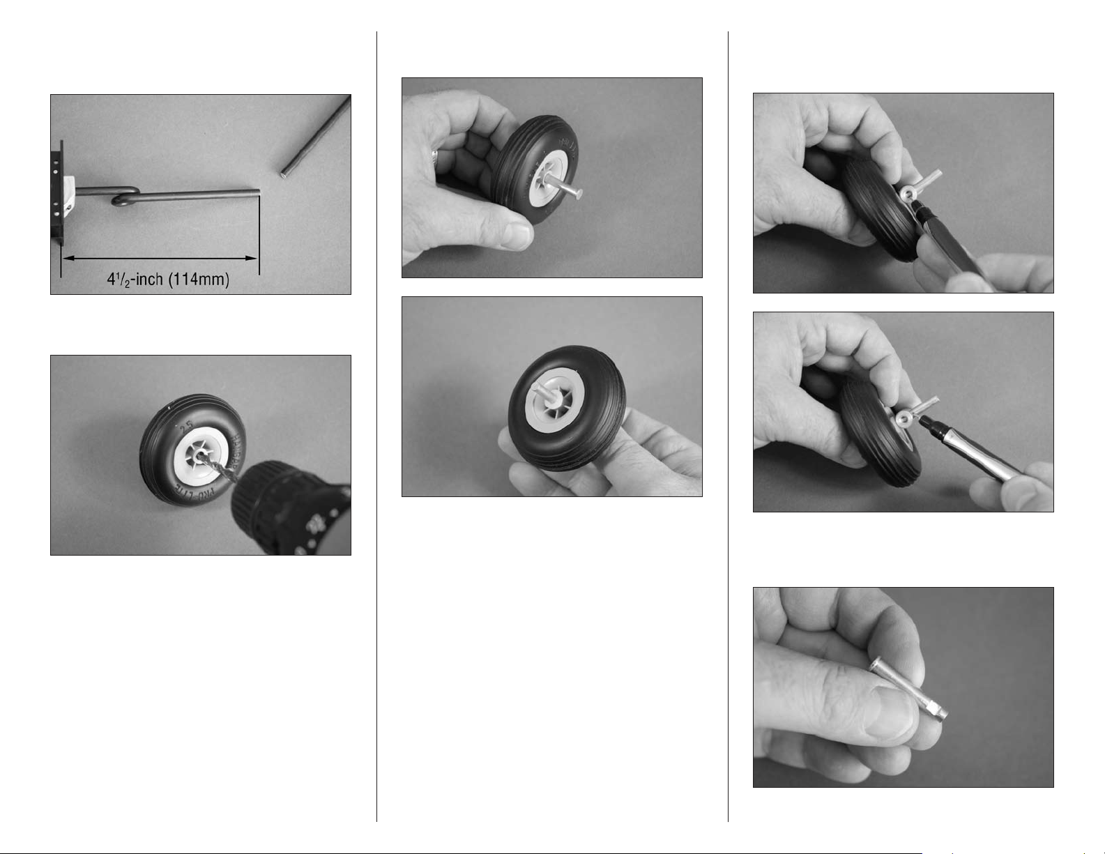
2. Use a rotary tool and cutoff wheel to cut the main
gear strut so it is 41/2-inch (114mm) when measured from
the top edge of the retract mounting flange as shown.
3. Use a drill and 3/16-inch (5mm) drill bit to enlarge
the hole in the wheel.
4. Slide the axle through the hole in the wheel. Slide
two nylon spacers on the axle from the opposite side.
5. Slide the adapter on the axle. Use a felt-tipped pen
to mark the location for the setscrew and the outside edge
where the axle will need trimmed.
Note: We recommend the use of a drill press to enlarge
the hole in the wheel so it is straight.
6. Use a rotary tool and cutoff wheel to trim the length
of the axle. Use a flat file to make a 1/4-inch (6mm) wide flat
where the setscrew from the adapter will rest.
39Hangar 9 Jackal 50 ARF
Page 40
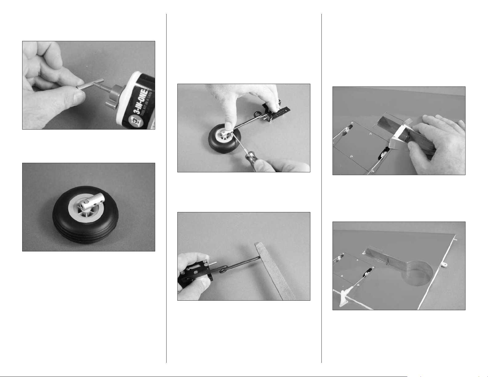
7. Place a drop of light machine oil on the axle before
sliding it into the wheel so it rolls smoothly during takeoff
and landing.
9. Tighten the wheel assembly to the main gear
strut. Use the setscrews provided with the axle adapters
and a 5/64-inch hex wrench to tighten the setscrews. The
setscrews will leave a mark on the strut where you will file in
the next step.
11. You can now attach the wheel assembly to the
strut using the setscrews and a 5/64-inch hex wrench. Make
sure to use threadlock on the setscrews to prevent them
from vibrating loose. Make sure the wheel is perpendicular
to the retract actuator before tightening the setscrews.
8. Assemble the axle and wheel as shown. Use
threadlock on the setscrew before tightening it on the flat
area made in the previous step.
Hint: With the retract mechanism in the up position,
hold the retract frame and wheel flat on your work
surface. This will set the wheel to the correct alignment.
10. Use a flat file to make a flat on the strut for the
setscrews. This will provide an area for the setscrews to be
tightened on, and prevent the wheel from rotating during
take-off and landing.
12. Use a hobby knife to cut the covering down the
center of the opening in the wing for the retract. Peel the
covering back to expose the balsa brace near the opening for
the mechanism.
13. Use a hobby knife to carefully remove the brace.
Trim the covering so you will have roughly 1/8-inch
(3mm) of covering that will be ironed into the wheel well.
Use a covering iron or trim seal tool to iron the covering,
completing the retract wheel well.
40 Hangar 9 Jackal 50 ARF
Page 41
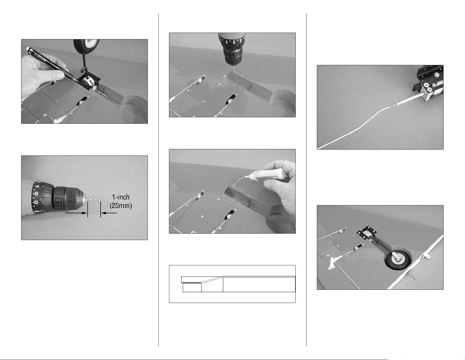
14. Place the retract mechanism in the wing. Use a
Jackal pushrods for mechanical mains
11/16-inch
(27mm)
5/16-inch
(9mm)
11/4-inch
(32mm)
43/16-inch
(106mm)
pencil to transfer the mounting locations for the screws on
the landing gear rails.
15. Place the 3/32-inch (2.5mm) drill bit in the drill.
Set the drill so it is 1-inch (25mm) from the chuck to prevent
accidentally drilling through the top of the wing.
16. Drill the four mounting holes for the landing gear
base using the drill and drill bit prepared in the previous step.
17. Place 2–3 drops of thin CA in each hole to harden
the surrounding wood. This makes it difficult for the screw
to pull loose on hard landings.
19. Thread the 2-56 nut on the threads of the short
bent end of the pushrod. The pushrod is then threaded into
the actuator for the retracts. With the pushrod positioned
so the bend is toward the top of the retract, use needle
nose pliers to tighten the nut against the actuator to keep it
from rotating. Use threadlock to prevent the pushrod from
vibrating loose.
20. Repeat Steps 2 through 19 to prepare the opposite
retract mechanism.
21. Place the retract mechanism in the wing. The
spring faces toward the trailing edge of the wing as shown.
Use four #6 x 1-inch sheet metal screws and a #2 Phillips
screwdriver to secure the landing gear block in the wing.
18. Bend the retract linkage using the drawing. This
will allow the linkage to clear the wheel when the retract is in
the up position.
41Hangar 9 Jackal 50 ARF
Page 42
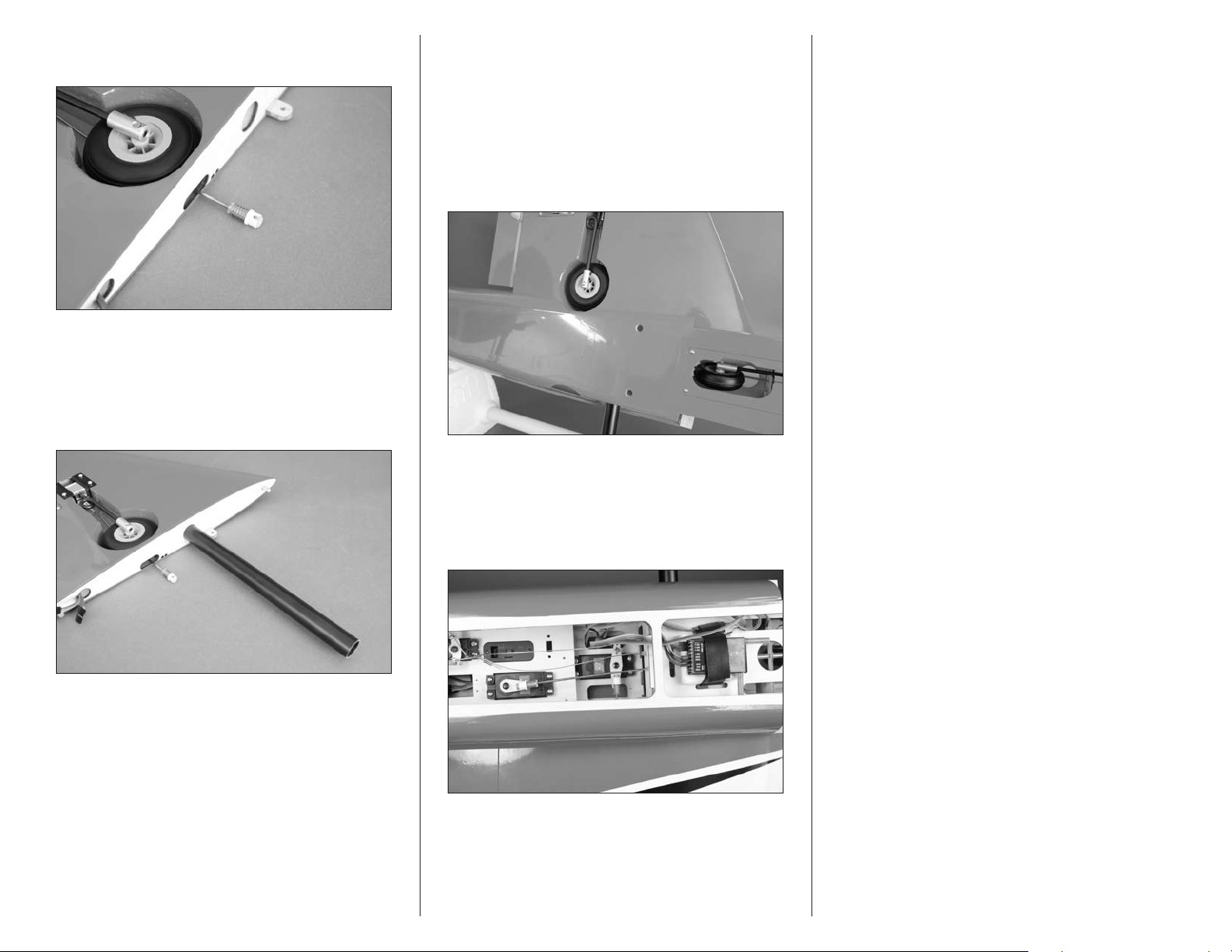
22. Thread the ball end on the pushrod wire. The
position will be adjusted in the next few steps.
24. Slide the wing panel into position in the fuselage.
Use a 4-40 x 1-inch socket head screw and #4 washer to
hold the wing in position. You don’t need to tighten the
screw, it is just holding the wing in position.
26. Use the radio system to move the retract servo to
the down position. Check that the gear is down and locked at
this time. If not, adjust the length of the linkage as necessary
to make sure the gear is down and locked.
Important: The wing installation in this section
is only for adjusting the retracts. Please follow the
procedure in “Wing Installation” for the complete
details for the wing installation.
23. Slide the wing tube into the wing panel.
Note: Setting the linkage correctly will take some time
and patience. Work slowly and make small adjustments
to the linkage so the main gear retract operates
correctly.
25. Use the radio system to move the retract servo
to the up position. Move the linkage so the main gear is
in the up and locked position. Connect the ball end to the
ball on the servo arm. You may need to adjust the length of
the linkage to get the ball end to align with the ball on the
servo horn.
Note: Check to make sure the nose gear and main gear
are moving up and down together. If you find the nose
gear up when the main gear is down, remove the servo
horn from the nose gear retract servo and rotate it
180-degrees so the gears move in unison.
27. Use the radio to cycle the gear a number of times,
checking that the length of the linkage is correct. Although
it is important the gear locks in both the up and down
positions, it is most critical it is fully locked when down or
it may collapse on the runway during takeoff or landing.
Also make sure the servo is not binding at either position,
as this will quickly drain the receiver battery. Take your time
to set the linkage perfectly. Once complete, tighten the 2-56
nut against the retract actuator to prevent it from changing
position.
28. Repeat Steps 21 through 26 to prepare and install the
remaining main landing gear retract.
42 Hangar 9 Jackal 50 ARF
Page 43
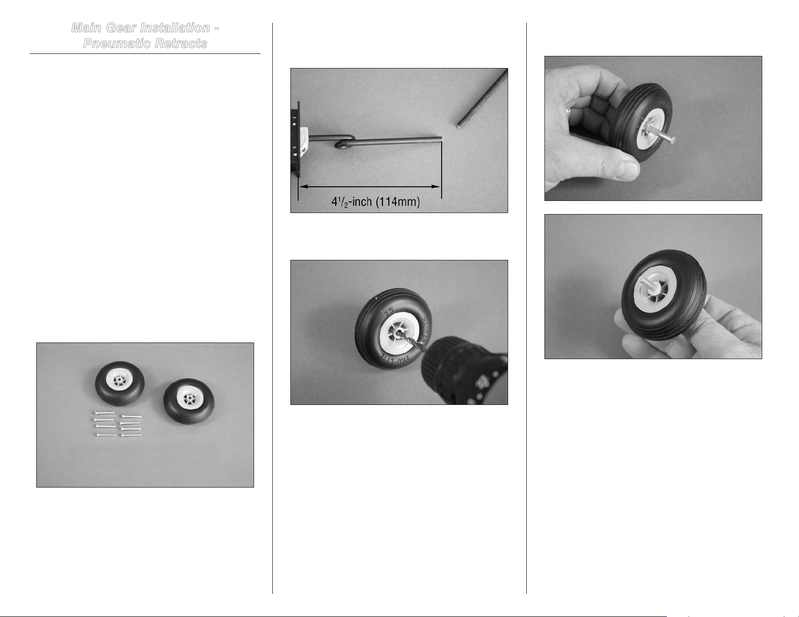
Main Gear Installation -
Pneumatic Retracts
Required Parts
Air line Quick disconnect (2)
Wing panel (right and left)
Main wheel, 2.5-inch (63.5mm) (2)
#6 x 1-inch sheet metal screw (8)
Required Tools and Adhesives
Rotary tool Cutoff wheel
Hobby knife with #11 blade Covering iron
Sealing iron Ruler
Felt-tipped pen
Phillips screwdriver: #2 Drill
Pencil Thin CA
Threadlock Flat file
Light machine oil Hex wrench: 5/64-inch
Drill bit: 3/32-inch (2.5mm), 3/16-inch (5mm)
1. Locate the items necessary to install the main pneumatic
retracts in the wing panels. You will also need the right
and left wing panels from your model as well as the retract
mechanism, axles and air line kit for both wing panels.
2. Use a rotary tool and cutoff wheel to cut the main
gear strut so it is 41/2-inch (114mm) when measured from
the top edge of the retract mounting flange as shown.
3. Use a drill and 3/16-inch (5mm) drill bit to enlarge
the hole in the wheel.
4. Slide the axle through the hole in the wheel. Slide
two nylon spacers on the axle from the opposite side.
Note: We recommend the use of a drill press to enlarge
the hole in the wheel so it is straight.
43Hangar 9 Jackal 50 ARF
Page 44
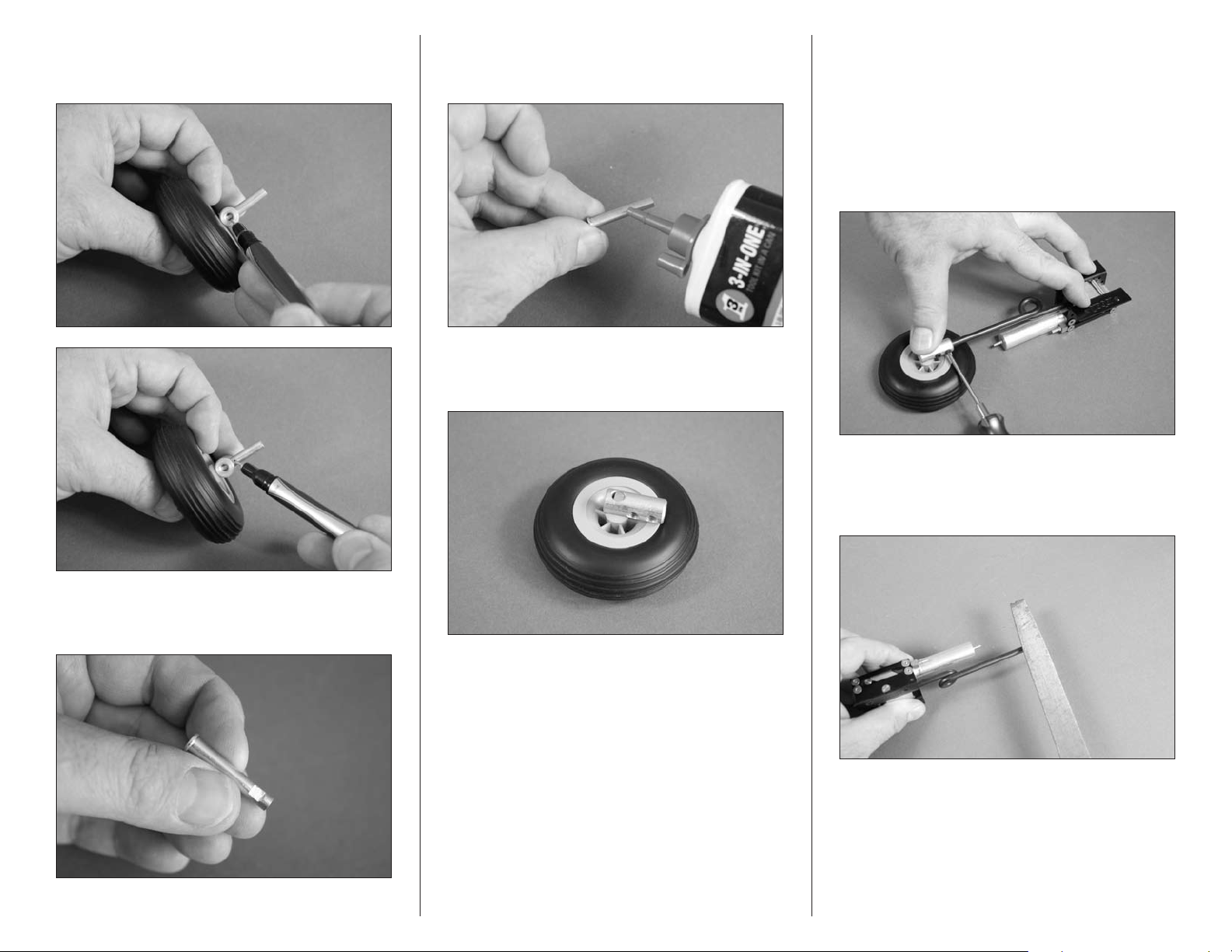
5. Slide the adapter on the axle. Use a felt-tipped pen
to mark the location for the setscrew and the outside edge
where the axle will need trimmed.
7. Place a drop of light machine oil on the axle before
sliding it into the wheel so it rolls smoothly during takeoff
and landing.
8. Assemble the axle and wheel as shown. Use
threadlock on the setscrew before tightening it on the flat
area made in the previous step.
9. Tighten the wheel assembly to the main gear
strut. Use the setscrews provided with the axle adapters
and a 5/64-inch hex wrench to tighten the setscrews. The
setscrews will leave a mark on the strut where you will file in
the next step.
Hint: With the retract mechanism in the up position,
hold the retract frame and wheel flat on your work
surface. This will set the wheel to the correct alignment.
10. Use a flat file to make a flat on the strut for the
setscrews. This will provide an area for the setscrews to be
tightened on, and prevent the wheel from rotating during
takeoff and landing.
6. Use a rotary tool and cutoff wheel to trim the length
of the axle. Use a flat file to make a 1/4-inch (6mm) wide flat
where the setscrew from the adapter will rest.
11. You can now attach the wheel assembly to the
strut using the setscrews and a 5/64-inch hex wrench. Make
sure to use threadlock on the setscrews to prevent them
from vibrating loose. Make sure the wheel is perpendicular
to the retract actuator before tightening the setscrews.
44 Hangar 9 Jackal 50 ARF
Page 45
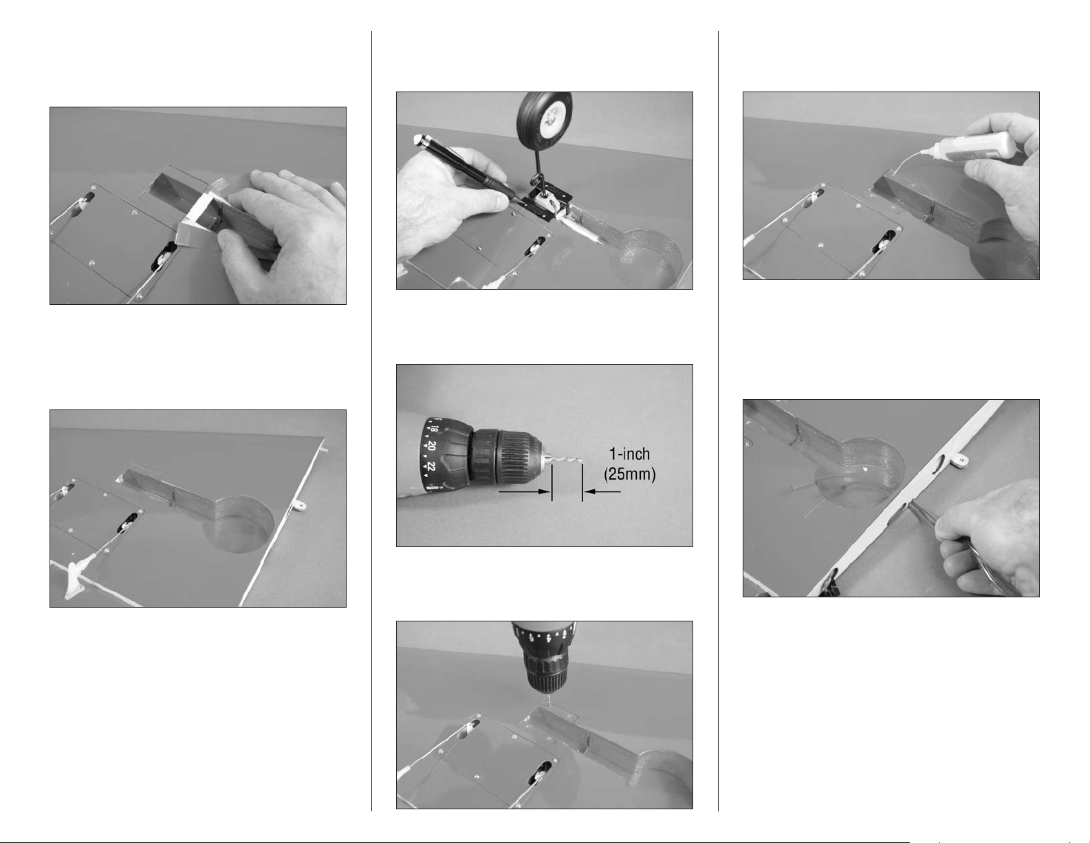
12. Use a hobby knife to cut the covering down the
center of the opening in the wing for the retract. Peel the
covering back to expose the balsa brace near the opening for
the mechanism.
15. Place the retract mechanism in the wing. Use a
pencil to transfer the mounting locations for the screws on
the landing gear rails.
18. Place 2–3 drops of thin CA in each hole to harden
the surrounding wood. This makes it difficult for the screw
to pull loose on hard landings.
13. Use a hobby knife to carefully remove the brace.
Trim the covering so you will have roughly 1/8-inch
(3mm) of covering that will be ironed into the wheel well.
Use a covering iron or trim seal tool to iron the covering,
completing the retract wheel well.
14. Repeat Steps 2 through 13 to prepare and install the
remaining main landing gear retract.
16. Place the 3/32-inch (2.5mm) drill bit in the drill.
Set the drill so it is 1-inch (25mm) from the chuck to prevent
accidentally drilling through the top of the wing.
17. Drill the four mounting holes for the landing
gear base using the drill and drill bit prepared in the
previous step.
19. Cut two 8-inch (230mm) pieces of air line (one
of each color) using scissors or a hobby knife and #11
blade. Insert the air lines through the holes in the root of
the wing from the outside of the wing. You may need to
use a hobby knife and #11 blade to trim the holes through
the foam of the wing.
Note: We recommend Robart air line with a 1/16-inch
inside diameter and 1/8-inch outside diameter for
connecting your retracts. Use two different colored lines
to differentiate the air line for Up and Down actuation
of the retract. Use the drawing on Page 53 for more
information regarding the routing of the air lines for
your model.
45Hangar 9 Jackal 50 ARF
Page 46
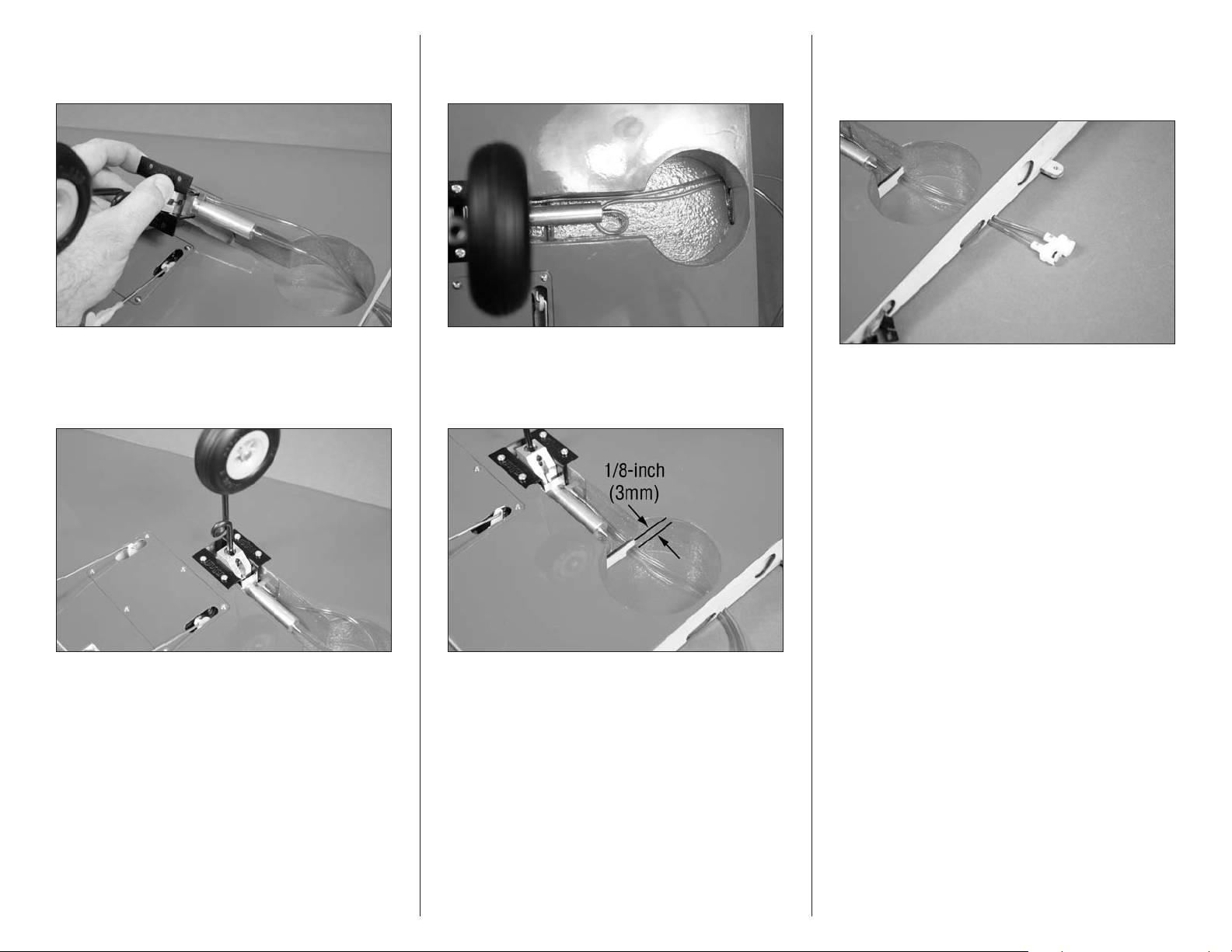
20. Attach the air lines to the retract air cylinder.
Use the instructions included with the retracts to connect
the lines.
22. Loop the air line from the end of the air cylinder
back under the cylinder. This will keep it from kinking when
installing the air line brace.
24. Use side cutters to trim the tubing 1
(37mm) from the end of the wing root. Install the air line
quick connect fittings on the tubes according to the Robart
instructions.
1
/2-inch
21. Place the retract mechanism in the wing. The
spring faces toward the trailing edge of the wing as shown.
Use four #6 x 1-inch sheet metal screws and a #2 Phillips
screwdriver to secure the landing gear block in the wing.
23. Use 30-minute epoxy to glue the air line brace into
the wing. Set the brace back 1/8-inch (3mm) from the wheel
well so it does not interfere with the wheel when the gear is
in the up position.
Hint: We install opposing fittings to make sure the up
and down air lines are not connected incorrectly when
assembling the model at the field.
25. Repeat Steps 15 through 24 to prepare and install the
remaining main landing gear retract.
46 Hangar 9 Jackal 50 ARF
Page 47
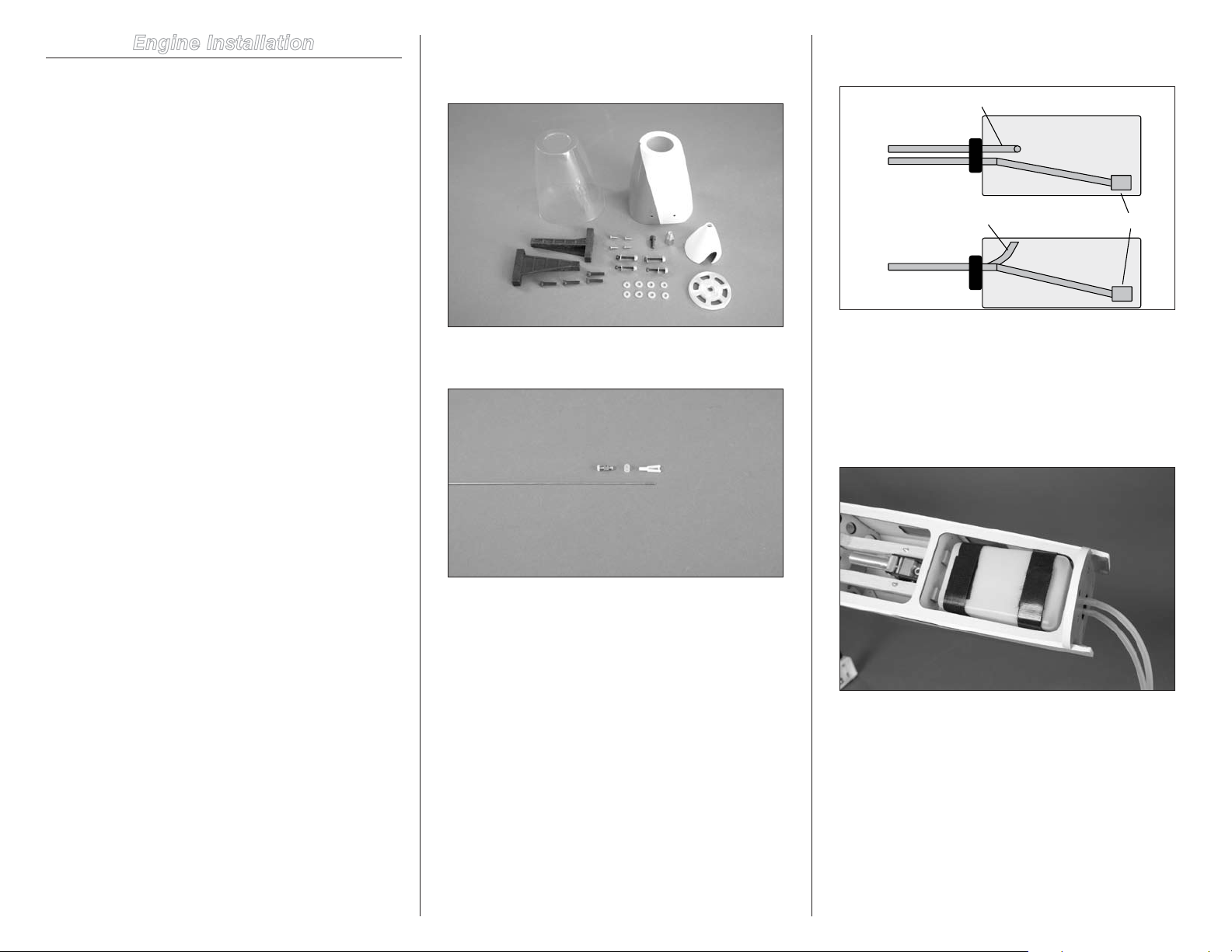
Engine Installation
Clunk
Vent Line
Top View
Side View
Vent Line (faces top of fuselage)
To Muffler
To Carburetor
Required Parts
Fuselage assembly Engine mount rails (2)
#8 washer (4) #6 washer (4)
6-32 locknut (4) Nylon clevis, small
Silicone clevis retainer Spinner cone
Spinner backplate Spinner adapter
2mm x 787mm pushrod Transmitter
Fuel tank Hook and loop strap
2mm x 31-inch (787 mm) pushrod
Clear cowling template
Painted cowling
Brass pushrod connector
10-32 x 5/8-inch socket head machine screw
Nylon pushrod connector backplate
8-32 x 3/4-inch socket head machine screw (4)
6-32 x 1-inch socket head machine screw (4)
3mm x 4mm machine screw
4-40 x 3/8-inch button head screw (4)
Required Parts (not included)
Servo with hardware Engine
Muffler
1. Locate the items necessary to install the engine. You
will also need the fuselage assembly, which includes the fuel
tank.
Don’t forget the pushrod linkage and other items to connect
the throttle servo to the carburetor.
2. Inspect the fuel tank to determine the correct
orientation before installing it into the fuselage.
3. Place the fuel tank in the fuselage, securing it with the
hook and loop straps.
Note: You will be required to drill the engine mount for
the engine. If you will NOT be using a drill press, make
sure to use threadlock on the screws that attach the
engine mount rails to the firewall in the following step.
Required Tools and Adhesives
Low-tack tape Drill
Nut driver: 5/16-inch Hobby scissors
Threadlock Pin vise
Felt-tipped pen Phillips screwdriver: #1
Ruler Open end wrench: 12mm
Side cutter Thin CA
Pencil
Rotary tool with sanding drum
Drill bit: 5/64-inch (3mm), 9/64-inch (3.5mm)
Ball driver or hex wrench: 5/64-inch, 7/64-inch,
1/8-inch, 4mm or 5/32-inch
47Hangar 9 Jackal 50 ARF
Page 48
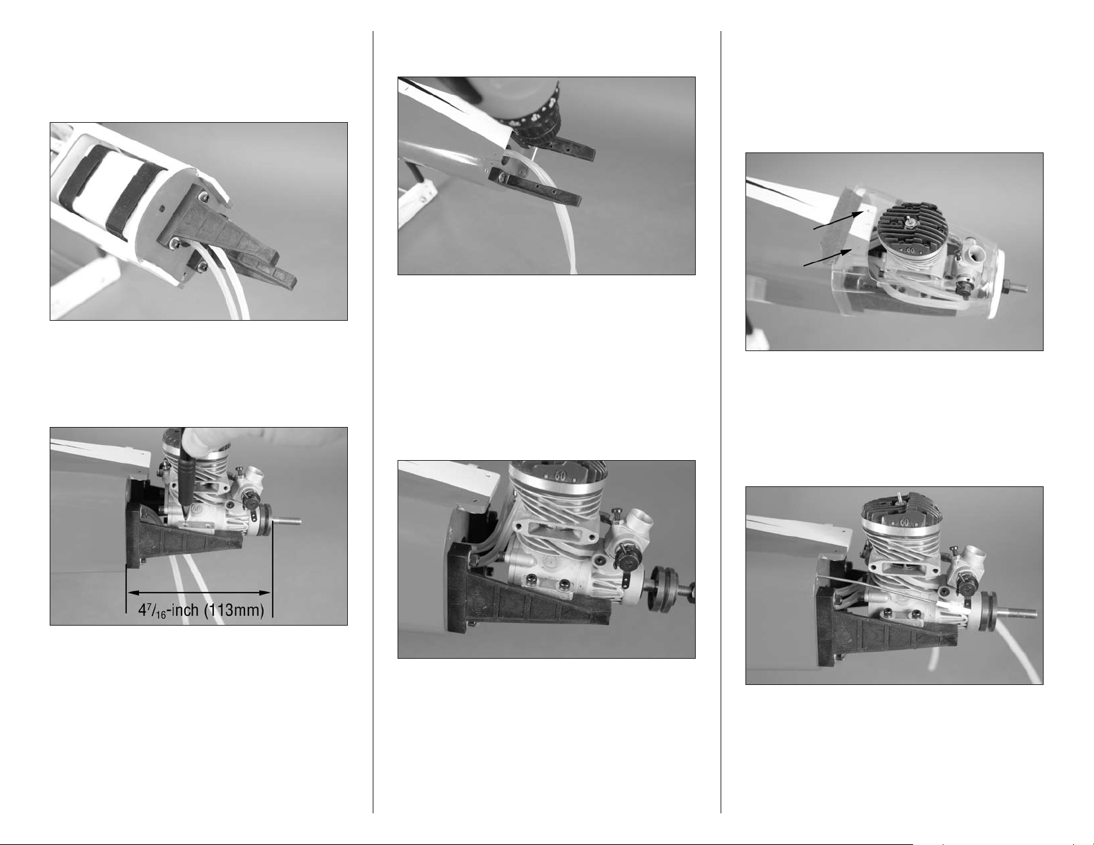
4. Attach the engine mount rails to the firewall using four
8-32 x 3/4-inch socket head machine screws and four #8
washers. Use a 1/8-inch hex wrench or ball driver to tighten
the screws. Make sure to use threadlock on the screws so
they don’t vibrate loose in flight.
5. Position the engine on the rails. Measure the
distance from the firewall to the front face of the drive
washer. Adjust the engine so this measurement is 47/16-
inch (113mm). Mark the engine mount rails for the engine
mounting screws using a pencil.
6. Use a drill and 9/64-inch (3.5mm) drill bit to drill the
four holes in the engine mount rails for mounting the engine.
Hint: It is recommended to use a drill press for drilling
the holes in the engine mount rails. This will make
them nice and straight in the rails. Make sure to use
threadlock on the screws that attach the rails to the
firewall when installing the rails back on the firewall.
7. Use four 6-32 x 1-inch socket head machine screws,
four #6 washers and four 6-32 locknuts to attach the engine
to the mounting rails. Use a 5/16-inch nut driver and 7/64inch hex wrench or ball driver to tighten the hardware.
8. Trim the clear cowling to fit the engine. We placed the
spinner backplate on the engine crankshaft to help locate
the clear cowling while trimming. Use low-tack tape to hold
the cowling in position on the fuselage. Use a felt-tipped
pen to mark the locations for the cowl mounting screws on
the clear template. This will help when aligning the clear
template to the painted cowl.
9. Slide a silicone clevis retainer over the small nylon
clevis. Thread the clevis on the throttle pushrod and slide
the pushrod into the tube in the firewall. Connect the clevis
to the outer hole of the carburetor arm and slide the clevis
retainer over the forks of the clevis to prevent it from
opening accidentally. Bend the pushrod slightly so it does
not bind when the carburetor is opened or closed.
48 Hangar 9 Jackal 50 ARF
Page 49
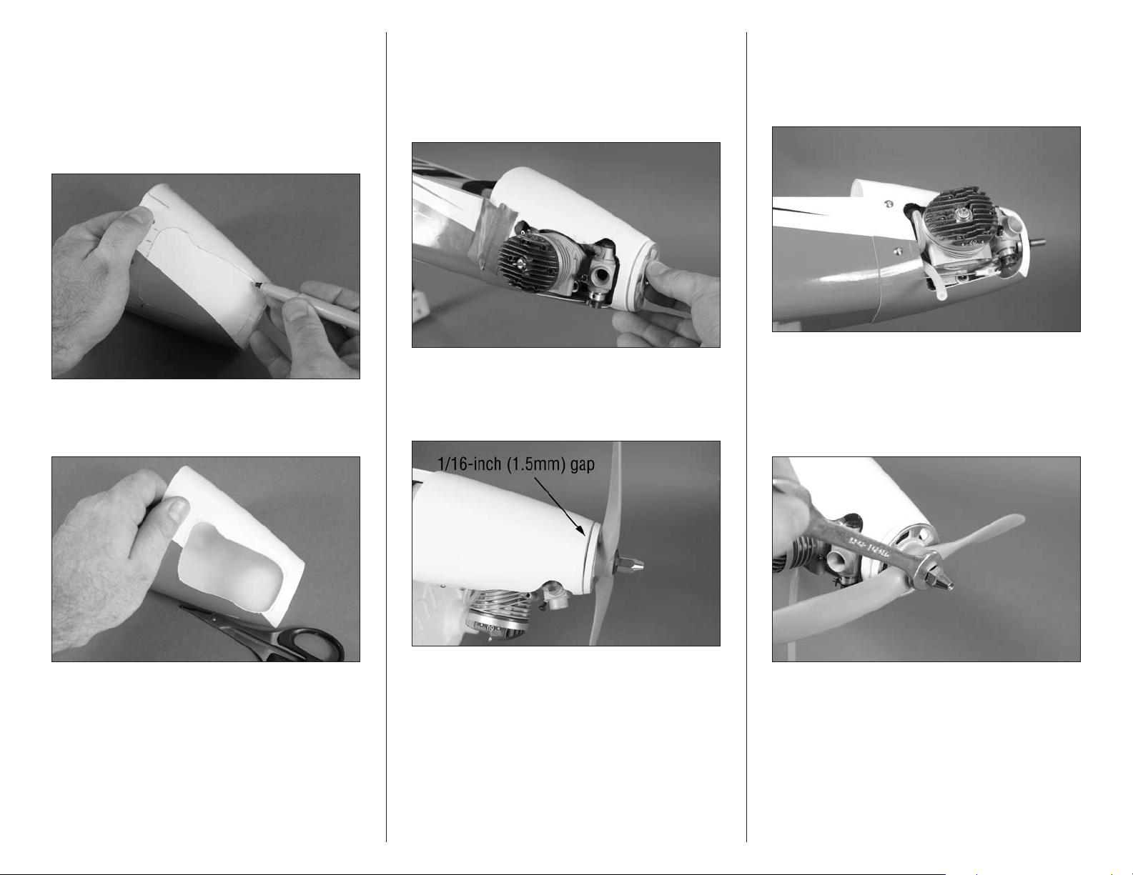
10. Slide the clear cowling over the painted cowling.
Align the marks made on the clear cowl in Step 8 for the
cowl mounting screws to align the clear cowl and painted
cowl. Use a felt-tipped pen to transfer the opening from the
clear cowling to the painted cowling. Make the marks on the
painted cowling roughly 1/8-inch (3mm) inside the opening
in the clear cowling to allow some material to remove when
making the final fit of the painted cowling.
11. Use hobby scissors to rough the opening for the
engine. Cut the cowling along the paint line behind the
engine so it can be installed and removed easily.
12. Use a rotary tool and sanding drum to fit the cowl
to the engine. Work slowly removing small amounts of
material. Use the spinner backplate and cowl mounting holes
to help in aligning the cowling while trimming. The cowl only
needs to fit over the engine at this time. Final adjustments
can be made once the cowl is secured to the fuselage.
13. Check that there is a gap of 1/16-inch (1.5mm)
between the spinner backplate and cowling. If not, slightly
oval the mounting holes in the cowl so there is a small gap
to prevent the backplate from rubbing on the cowl.
14. Attach the cowling to the fuselage using four 4-40 x
3/8-inch button head screws. Use a 5/64-inch hex wrench or
ball driver to tighten the screws. Trim and connect the fuel
line connected to the fuel tank clunk line to the carburetor
fuel inlet nipple.
15. Attach the propeller and spinner backplate to the
crankshaft using the washer included with the engine and the
adapter included with the model. Use a 12mm open end or
box wrench to tighten the nut. Do not use pliers as this will
not tighten the nut and will round the corners so a box or
open end wrench won’t fit.
49Hangar 9 Jackal 50 ARF
Page 50
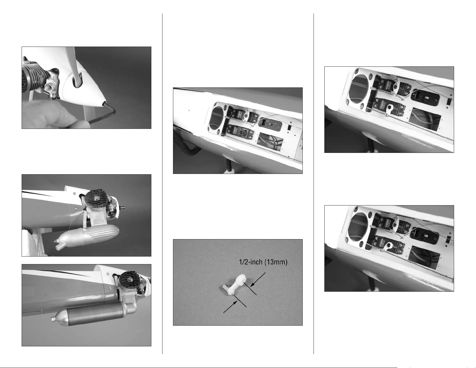
16. Place the spinner cone on the backplate so the
openings for the propeller in the cone are not touching the
propeller. Use a 4mm hex wrench or ball driver to install the
spinner mounting screw.
17. Attach the muffler to the engine using the hardware
included with the muffler. Connect the line from the fuel tank
vent to the muffler. Trim the line so it won’t interfere with the
operation of the engine. Use a small amount of threadlock on
the screws to prevent them from vibrating loose.
Hint: The installation of the optional EVOM1 muffler
will increase the speed of the engine over 1500 rpm on
an APC 10 x 7 propeller.
18. Place 2–3 drops of thin CA in the holes for the
throttle servo mounting screws. Remove the horn from the
throttle servo and use the hardware included with the servo
and a #1 Phillips screwdriver to mount the throttle servo in
the fuselage. Route the lead from the servo under the tray
and plug it into the throttle port of the receiver.
19. Prepare the servo horn for the throttle by enlarging
a hole that is 1/2-inch (13mm) from the center of the horn
using a pin vise and 5/64-inch (2mm) drill bit. Insert the
brass pushrod connector in the hole of the servo horn that
is 1/2-inch (13mm) from the center of the horn. Use the
connector backplate to secure the connector to the horn. Use
side cutters to remove any arm on the horn that will interfere
with the operation of the radio system.
20. Center the throttle servo using the radio system.
Slide the pushrod wire through the hole in the brass
pushrod connector and attach the servo horn to the throttle
servo so it is perpendicular to the servo center line. This
provides equal throw to both low and high throttle. Secure
the horn using the screw removed from the servo and a #1
Phillips screwdriver.
21. Move the throttle servo to the low-throttle position
using the radio system. Use the linkage to close the
carburetor then use the 3mm x 4mm machine screw to
secure the pushrod to the brass pushrod connector. Use
threadlock on all metal-to-metal fasteners to prevent them
from vibrating loose.
50 Hangar 9 Jackal 50 ARF
Page 51
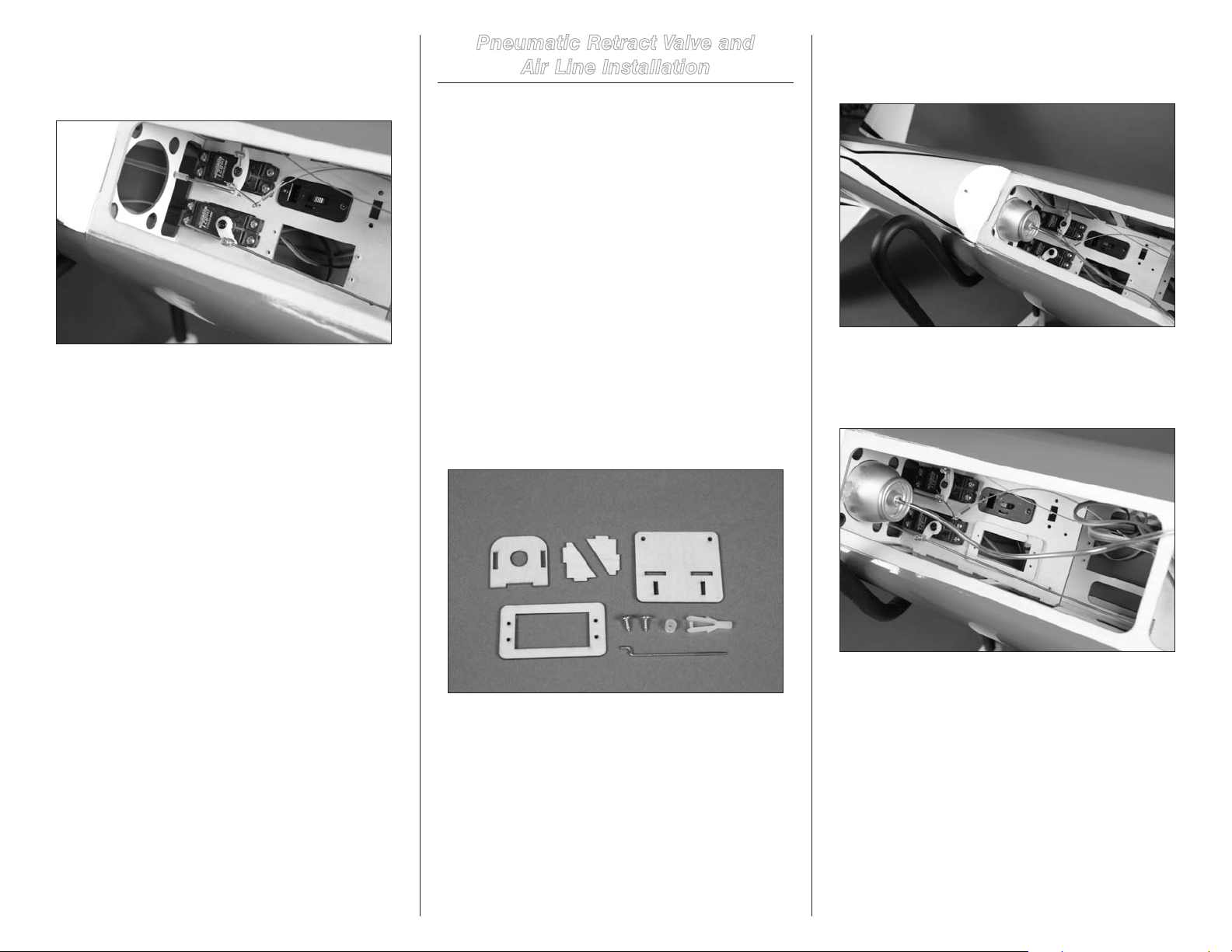
22. Use the radio system to move the carburetor to the
high-throttle position. If the servo binds, use the setting in
the radio to reduce the throw. If the carburetor is not fully
open, use the radio setting so the carburetor opens fully.
Pneumatic Retract Valve and
Air Line Installation
Required Parts
Fuselage assembly
Air valve mount base Air valve mount
Air valve mount support (2) 2-56 x 2-inch pushrod
Nylon clevis Silicone clevis retainer
Plywood servo adapter plate
3mm x 8mm sheet metal screw (2)
Retract air valve kit
Required Tools and Adhesives
Phillips screwdriver: #1 Pin vise
Medium CA Pin vise
Drill bit: 1/16-inch (1.5mm), 5/64-inch (2mm)
Zap-A-Dap-A-Goo similar or flexible adhesive
1. Locate the items necessary to install the air valve in
the fuselage. You will also need to have the fuselage, along
with the appropriate air control kit for your model.
2. Attach an appropriate colored line to the air tank. Use a
very small amount of flexible adhesive to secure the air tank
in the fuselage as shown.
3. Use a small amount of medium CA to glue the plywood
servo adapter plate in the fuselage. Make sure to center the
adapter plate over the existing retract servo opening in the
servo tray as shown.
51Hangar 9 Jackal 50 ARF
Page 52
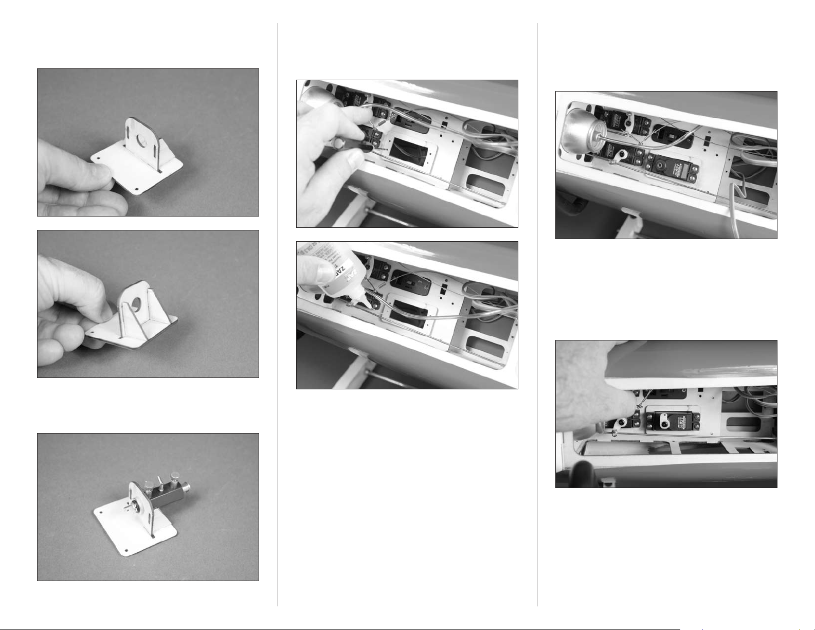
4. While the adhesives from the first few steps cure, you
can build the retract valve mount using medium CA. Make
sure all the joints are tight when assembling the mount.
6. Use a pin vise and 1/16-inch (1.5mm) drill bit to drill
the holes through the plywood servo adapter plate and into
the radio tray. Apply 2–3 drops of thin CA in each hole to
harden the surrounding wood.
7. Use the screws provided with the servo and a #1
Phillips screwdriver to secure the retract servo in the
fuselage. Make sure the output of the servo faces the rear
of the fuselage. Route the lead for the servo under the servo
tray and plug it into the retract port of the receiver.
8. Prepare a servo horn by enlarging the hole in the arm
that is as close to the center of the arm as possible using a
pin vise and 5/64-inch (2mm) drill bit. Use the radio to set
thethrowfortheretractservoto0%inbothdirections.This
will center the servo and allow you to set the throw for the
retract valve without causing damage to the servo, valve or
airframe by having more throw than necessary.
5. Attach the retract valve to the mount. Make sure to
position the valve so the mount does not interfere with the
air lines when they are connected to the valve.
52 Hangar 9 Jackal 50 ARF
Page 53
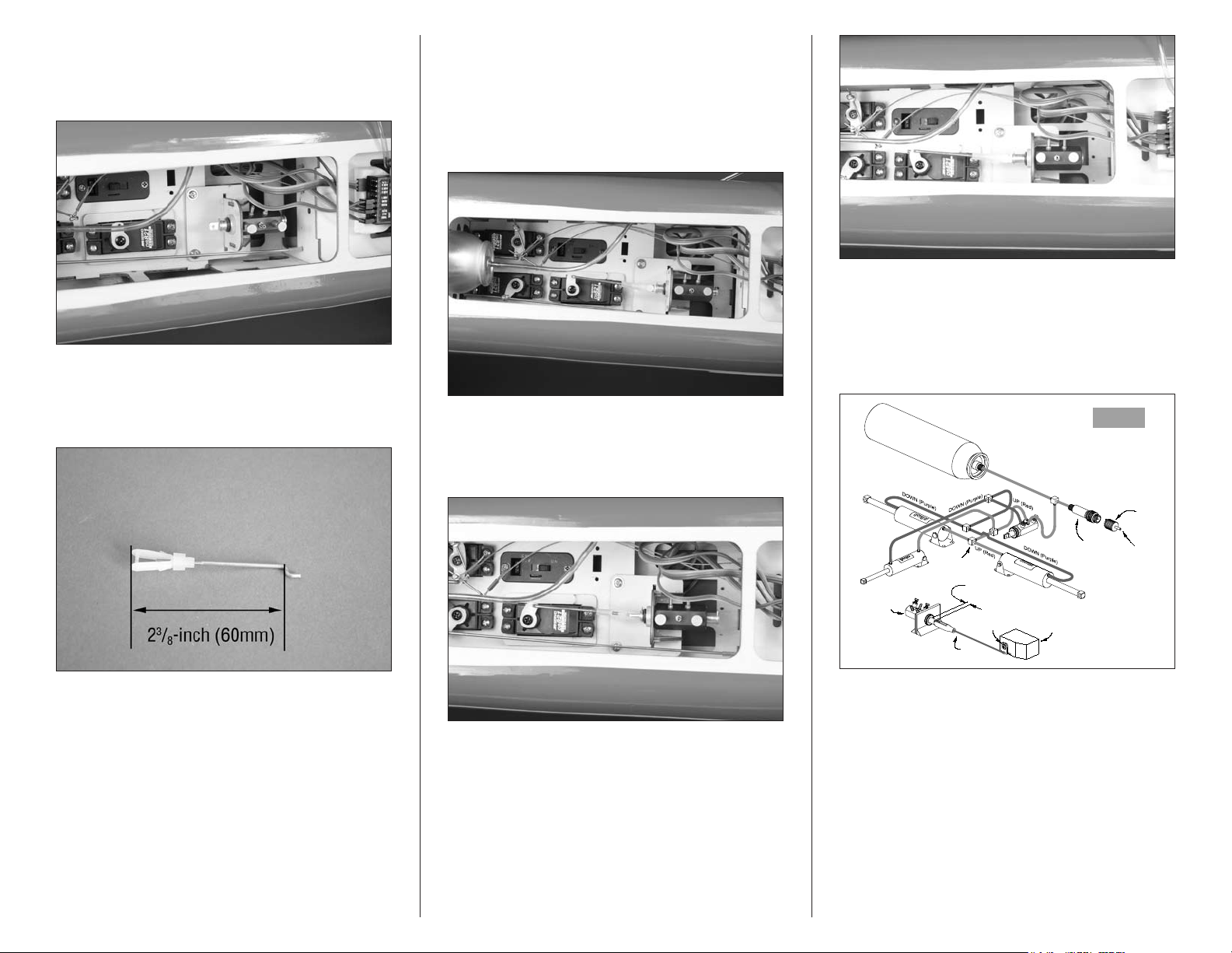
9. Place 2–3 drops of thin CA in each of the two retract
3 GEAR
INSTALLATION
Right Landing
Gear Cylinder
Nose
Gear
Cylinder
Tee
Fittings
Left Landing
Gear Cylinder
Servo
Arm
Link Rod
Assembly
Control
Valve
1/4" Travel
Maximum
Servo
Fill Valve
(AIR SUPPLY IN)
Fill Chuck
valve mounting holes in the radio tray. Use two 3mm x 8mm
sheet metal screws to attach the retract valve mount in the
fuselage. Tighten the screws using a #1 Phillips screwdriver.
10. Assemble the linkage for the retract valve using a
silicone clevis keeper, nylon clevis and the 2-56 x 2-inch
pushrod. Thread the clevis on the pushrod so the overall
length of the linkage is 23/8-inch (60mm).
11. Center the retract servo using the radio system
bysettingtheATV(orendpoint)valuesto0%.Installthe
linkage by inserting the bend in the linkage in the hole of the
servo horn. The clevis is then connected to the retract valve.
Check that the valve is in the center of the throw. Adjust the
clevis as necessary. Slice the retainer over the forks of the
clevis to keep it from opening accidentally.
13. Route the airlines in the fuselage for the air tank,
nose gear and main gear. Use the information provided
with the retract instructions to route the lines correctly.
Make sure that the fittings for the main gear are oriented
correctly so they work in unison with each other and with
the nose gear retract.
12. Use the ATV (or endpoints) in the programming of
your radio system to properly operate the retract valve.
It will only take a few percents in both directions to
operate the valve.
53Hangar 9 Jackal 50 ARF
Page 54
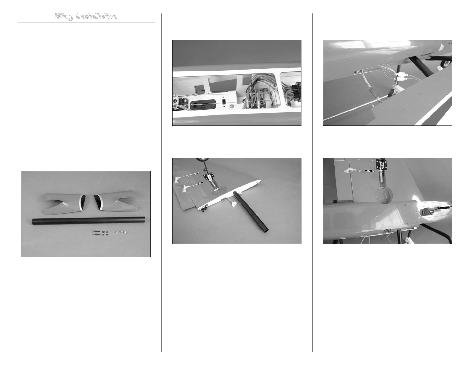
Wing Installation
Required Parts
Fuselage assembly #4 washer (2)
#4 lock washer (2) Aluminum wing tube
Wing assembly (right and left)
4-40 x 1-inch socket head machine screw (2)
Fiberglass inlet (right and left)
3mm x 8mm sheet metal screw (2)
1.7mm x 6mm sheet metal screw (2)
9-inch (228mm) servo extension (4)
Tie wraps (not included)
Required Tools and Adhesives
Phillips screwdriver: #1
Hex wrench or ball driver: 3/32-inch
1. Locate the items necessary to install the wing to
the fuselage. You will also need both wing panels and the
fuselage for this section of the manual.
3. Use tie wraps to secure the servo leads inside the
fuselage. This will prevent them from interfering with the
operation of the radio system inside the fuselage.
4. Slide the wing tube into one of the wing panels. The
tube will slide in easily, so don’t force it in farther than it will
slide easily.
5. Insert the tube into the fuselage. Before sliding the
panel tight against the fuselage, connect any extensions or
air lines at this time.
6. Guide the extensions (and air lines) into the
fuselage while sliding the wing into position. The wing will fit
tightly against the fuselage.
2. Plug the 9-inch (228mm) servo extensions into the
receiver for the flaps and ailerons. Route the extensions out
of the fuselage so the leads in the wing can be plugged in
when the wing is installed.
54 Hangar 9 Jackal 50 ARF
Page 55
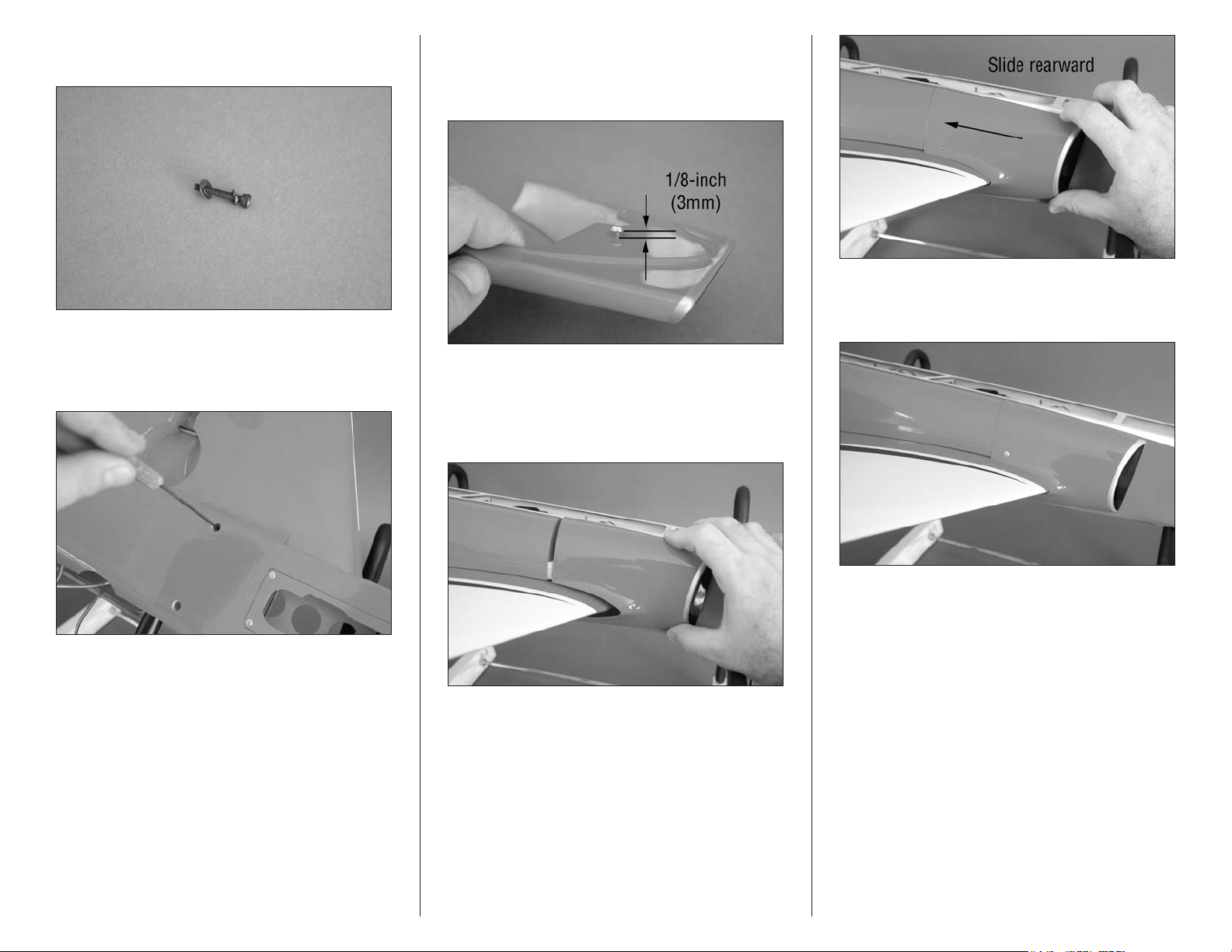
7. Slide a #4 lock washer, then a #4 washer on a
4-40 x 1-inch socket head machine screw.
8. Insert the screw into the hole in the bottom of the
fuselage. The screw will thread into the blind nut installed
in the wing. Use a 3/32-inch hex wrench or ball driver to
tighten the screw.
9. Use a #1 Phillips screwdriver to thread the 3mm x
8mm sheet metal screw into the fiberglass inlet. Allow a gap
of 1/8-inch (3mm) between the edge of the fairing and head
of the screw.
11. Use a 1.7mm x 6mm sheet metal screw to secure
the fairing in position. Use a #1 Phillips screwdriver to
tighten the screw.
10. The head of the screw will fit into the keyed
opening in the fuselage. Slide the fairing rearward and
against the leading edge of the wing. If the screw is too far
in, it may be difficult to install the fairing. Loosen the screw
slightly until the fairing can be installed.
12. Repeat Steps 5 through 11 to attach the remaining
wing panel to the fuselage.
13. Connect the linkages to the retract servo if you have
installed mechanical retracts.
55Hangar 9 Jackal 50 ARF
Page 56
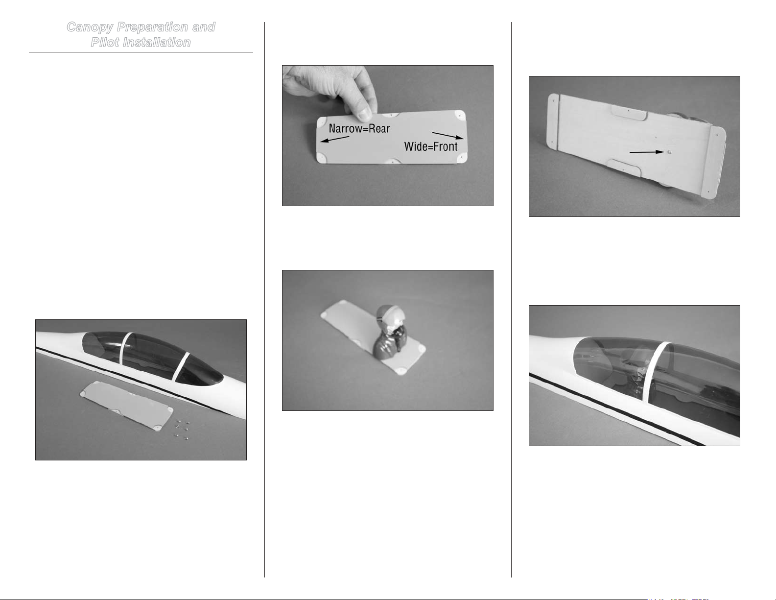
Canopy Preparation and
Pilot Installation
Required Parts
Canopy hatch Cockpit floor
1.5mm x 6mm sheet metal screw (6)
Required Tools and Adhesives
Phillips screwdriver: #1
Optional Required Items
Pilot figure (2) Medium CA
Drill bit: 1/16-inch (1.5mm) Pin vise
#2 x 1/2-inch sheet metal screw (2) (not included)
2. Before installing the pilots, make sure to determine the
front and rear of the canopy floor. The front of the floor is
wider than the rear as shown in the photo.
4. Use a pin vise and a 1/16-inch (1.5mm) drill bit to
drill a hole through the canopy floor and into the base of the
pilot. Use a #2 x 1/2-inch sheet metal screw to secure the
pilot to the canopy floor.
Note: This section covers the installation of two pilot
figures (optional) in the canopy. If you choose not to
install the pilots now, they can be added later. You
will need to install the canopy floor as described in
Step 6 and 7.
1. Locate the items necessary to attach the canopy floor
to the canopy. If you are installing pilots, you will also need
the items listed under the optional required items.
3. Use medium CA to glue the forward pilot figure to the
canopy floor. Position the pilot about half-way between the
front and center mounting holes. Make sure the shoulders of
the pilot hang over the edge of the canopy floor equally.
5. Use medium CA to glue the shoulders of the rear
pilot to the canopy frame. Allow the CA to fully cure before
proceeding.
Note: Do not use CA accelerator as it may damage the
canopy material.
56 Hangar 9 Jackal 50 ARF
Page 57
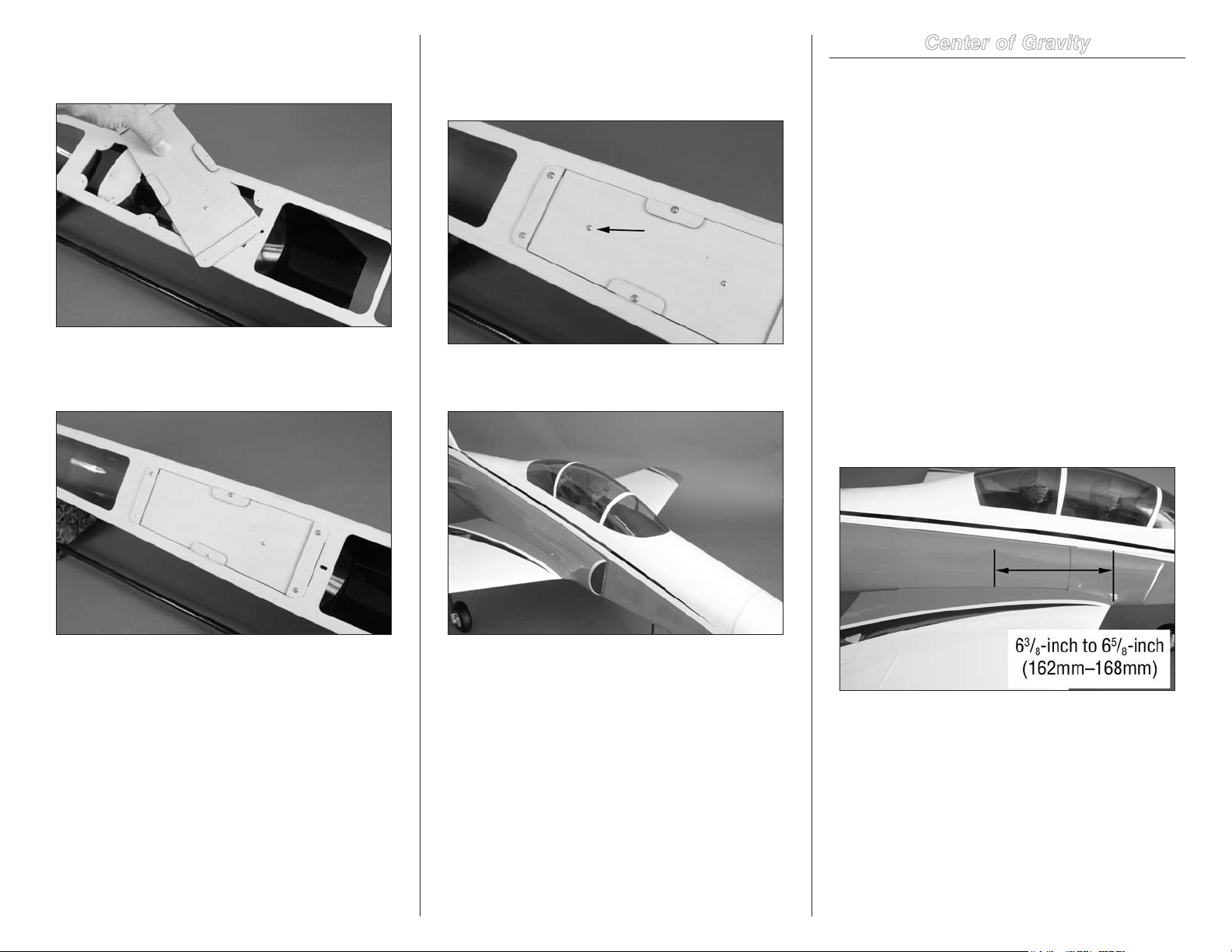
6. Position the canopy floor in the opening in the canopy
hatch. If you installed a pilot, you will need to rotate the
hatch to fit the shoulders of the front pilot.
7. Use six 1.5mm x 6mm sheet metal screws to secure
the canopy floor. Use a #1 Phillips screwdriver to tighten
the screws.
8. Use a pin vise and a 1/16-inch (1.5mm) drill bit to drill
a hole through the canopy floor and into the base of the rear
pilot. Use a #2 x 1/2-inch sheet metal screw to secure the
pilot to the canopy floor.
9. Attach the canopy to the fuselage to complete the build
of your model.
Center of Gravity
An important part of preparing the aircraft for flight is
properly balancing the model.
Caution: Do not inadvertently skip this step!
The recommended Center of Gravity (CG) location for your
model is 63/8-inch to 65/8-inch (162mm–168mm) back from
the leading edge of the wing as shown with the battery
pack installed. Mark the location of the CG on the top of the
wing with a felt-tipped pen.
When balancing your model, support the plane inverted
at the marks made on the wing with your fingers or a
commercially available balancing stand. This is the correct
balance point for your model. Make sure your model is
assembled and ready for flight before balancing.
Adjust the motor battery as necessary so the model is level
or slightly nose down. This is the correct balance point for
your model. You should find the CG to be very close with
the battery installed as shown in this manual. Mark the
location of the battery on the battery tray using a felt-tipped
pen so it can be returned to this position if it is removed
from your model.
After the first flights, the CG position can be adjusted for
your personal preference.
57Hangar 9 Jackal 50 ARF
Page 58

Control Throws
Rudder:
Preight
1. Turn on the transmitter and receiver of your model.
Check the movement of the rudder using the transmitter.
When the stick is moved right, the rudder should also move
right. Reverse the direction of the servo at the transmitter if
necessary.
2. Check the movement of the elevator with the radio
system. Moving the elevator stick toward the bottom of the
transmitter will make the airplane elevator move up.
3. Check the movement of the ailerons with the radio
system. Moving the aileron stick right will make the right
aileron move up and the left aileron move down.
4. Use a ruler to adjust the throw of the elevator, ailerons
and rudder.
Aileron:
High Rate:
Up: 1/2-inches 13mm 18 degrees
Down: 1/2-inches 13mm 18 degrees
Low Rate:
Up: 5/16-inches 8mm 15 degrees
Down: 5/16-inches 8mm 15 degrees
Elevator:
High Rate:
Up: 1-inches 25mm 22 degrees
Down: 3/4-inches 19mm 18 degrees
Low Rate:
Up: 3/4inches 19mm 18 degrees
Down: 1/2-inches 13mm 14 degrees
High Rate:
Right: 13/8-inches 35mm 28 degrees
Left: 1-inches 25mm 20 degrees
Low Rate:
Right: 1-inches 25mm 20 degrees
Left: 7/8-inches 22mm 18 degrees
Flap:
Mid: 23 degrees
Land: 42 degrees
Flap Mix to Elevator:
Mid:1degrees(6%)
Land:3degrees(13%)
These are general guidelines measured from our own flight
tests. You can experiment with higher rates to match your
preferred style of flying.
Note: Travel Adjust, Sub-Trim and Dual Rates are
not listed and should be adjusted according to each
individual model and preference.
Check Your Radio
Before going to the field, be sure your batteries are fully
charged per your radio’s instructions. Charge the transmitter
and motor battery for your airplane. Use the recommended
charger supplied with your particular radio system, following
the instructions provided with the radio. In most cases, the
radio should be charged the night before going out flying.
Before each flying session, be sure to range check your
radio. See your radio manual for the recommended
range and instructions for your radio system. Each radio
manufacturer specifies different procedures for their radio
systems. Next, run the motor. With the model securely
anchored, check the range again. The range test should not
be significantly affected. If it is, don’t attempt to fly! Have
your radio equipment checked out by the manufacturer.
Double-check that all controls (aileron, elevator, rudder and
throttle) move in the correct direction.
Check the radio installation and make sure all the control
surfaces are moving correctly (i.e., the correct direction and
with the recommended throws).
Check all the control horns, servo horns, and clevises to
make sure they are secure and in good condition.
Range Test Your Radio
Before each flying session, and especially with a new model,
it is important to perform a range check. It is helpful to have
another person available to assist during the range check. If
you are using a Spektrum transmitter, please refer to your
transmitter’s manual for detailed instructions on the range
check process.
58 Hangar 9 Jackal 50 ARF
Page 59
Safety Do’s and Don’ts for Pilots
•Consultlocallawsandordinancesbeforechoosinga
location to fly your aircraft.
•Checkallcontrolsurfacespriortoeachtakeoff.
•Donotflyyourmodelnearspectators,parkingareasor
any other area that could result in injury to people or
damage of property.
•Donotflyduringadverseweatherconditions.Poor
visibility can cause disorientation and loss of control of
your aircraft. Strong winds can cause similar problems.
•Donottakechances.Ifatanytimeduringflight
you observe any erratic or abnormal operation, land
immediately and do not resume flight until the cause of
the problem has been ascertained and corrected. Safety
can never be taken lightly.
•Donotflynearpowerlines.
Daily Flight Checks
•1.Checkthebatteryvoltageofthetransmitterbattery.
Do not fly below the manufacturer’s recommended
voltage. To do so can crash your aircraft.
When you check these batteries, ensure you have the
polarities correct on your expanded scale voltmeter.
•2.Checkallhardware(linkages,screws,nuts,andbolts)
prior to each day’s flight. Be sure that binding does not
occur and that all parts are properly secured.
•3.Ensureallsurfacesaremovinginthe
proper manner.
•4.Performagroundrangecheckbeforeeachday’s
flying session.
•5.Priortostartingyouraircraft,turnoffyour
transmitter, then turn it back on. Do this each time you
start your aircraft. If any critical switches are on without
your knowledge, the transmitter alarm will sound a
warning at this time.
•6.Checkthatalltrimleversareintheproperlocation.
•7.Allservopigtailsandswitchharnessplugsshouldbe
secured in the receiver. Make sure the switch harness
moves freely in both directions.
Warranty and Repair Policy
WARRANTY PERIOD
Exclusive Warranty- Horizon Hobby, Inc., (Horizon)
warranties that the Products purchased (the “Product”) will
be free from defects in materials and workmanship at the
date of purchase by the Purchaser.
LIMITED WARRANTY
Horizon reserves the right to change or modify this
warranty without notice and disclaims all other
warranties, express or implied.
(a) This warranty is limited to the original Purchaser
(“Purchaser”) and is not transferable. REPAIR OR
REPLACEMENT AS PROVIDED UNDER THIS WARRANTY
IS THE EXCLUSIVE REMEDY OF THE PURCHASER. This
warranty covers only those Products purchased from an
authorized Horizon dealer. Third party transactions are not
covered by this warranty. Proof of purchase is required for
all warranty claims.
(b) Limitations- HORIZON MAKES NO WARRANTY OR
REPRESENTATION, EXPRESS OR IMPLIED, ABOUT
NON-INFRINGEMENT, MERCHANTABILITY OR FITNESS
FOR A PARTICULAR PURPOSE OF THE PRODUCT. THE
PURCHASER ACKNOWLEDGES THAT THEY ALONE HAVE
DETERMINED THAT THE PRODUCT WILL SUITABLY MEET
THE REQUIREMENTS OF THE PURCHASER’S INTENDED
USE.
(c) Purchaser Remedy- Horizon’s sole obligation hereunder
shall be that Horizon will, at its option, (i) repair or (ii)
replace, any Product determined by Horizon to be defective.
In the event of a defect, these are the Purchaser’s exclusive
remedies. Horizon reserves the right to inspect any and
all equipment involved in a warranty claim. Repair or
replacement decisions are at the sole discretion of Horizon.
This warranty does not cover cosmetic damage or damage
due to acts of God, accident, misuse, abuse, negligence,
commercial use, or modification of or to any part of the
Product. This warranty does not cover damage due to
improper installation, operation, maintenance, or attempted
repair by anyone other than Horizon. Return of any Product
by Purchaser must be approved in writing by Horizon before
shipment.
DAMAGE LIMITS
HORIZON SHALL NOT BE LIABLE FOR SPECIAL, INDIRECT
OR CONSEQUENTIAL DAMAGES, LOSS OF PROFITS OR
PRODUCTION OR COMMERCIAL LOSS IN ANY WAY
CONNECTED WITH THE PRODUCT, WHETHER SUCH CLAIM
IS BASED IN CONTRACT, WARRANTY, NEGLIGENCE, OR
STRICT LIABILITY. Further, in no event shall the liability of
Horizon exceed the individual price of the Product on which
liability is asserted. As Horizon has no control over use,
setup, final assembly, modification or misuse, no liability
shall be assumed nor accepted for any resulting damage or
injury. By the act of use, setup or assembly, the user accepts
all resulting liability.
If you as the Purchaser or user are not prepared to accept
the liability associated with the use of this Product, you
are advised to return this Product immediately in new and
unused condition to the place of purchase.
Law: These Terms are governed by Illinois law (without
regard to conflict of law principals).
59Hangar 9 Jackal 50 ARF
Page 60
Warranty Services
QUESTIONS, ASSISTANCE, AND REPAIRS
Your local hobby store and/or place of purchase cannot
provide warranty support or repair. Once assembly, setup
or use of the Product has been started, you must contact
Horizon directly. This will enable Horizon to better answer
your questions and service you in the event that you may
need any assistance. For questions or assistance, please
direct your email to [email protected], or
call 877.504.0233 toll free to speak to a Product Support
representative. You may also find information on our website
at www.horizonhobby.com.
INSPECTION OR REPAIRS
If this Product needs to be inspected or repaired, please
use the Horizon Online Repair Request submission process
found on our website or call Horizon to obtain a Return
Merchandise Authorization (RMA) number. Pack the Product
securely using a shipping carton. Please note that original
boxes may be included, but are not designed to withstand
the rigors of shipping without additional protection. Ship
via a carrier that provides tracking and insurance for lost
or damaged parcels, as Horizon is not responsible for
merchandise until it arrives and is accepted at our facility. An
Online Repair Request is available at www.horizonhobby.com
http://www.horizonhobby.com under the Repairs tab. If you
do not have internet access, please contact Horizon Product
Support to obtain a RMA number along with instructions for
submitting your product for repair. When calling Horizon,
you will be asked to provide your complete name, street
address, email address and phone number where you can
be reached during business hours. When sending product
into Horizon, please include your RMA number, a list of the
included items, and a brief summary of the problem. A copy
of your original sales receipt must be included for warranty
consideration. Be sure your name, address, and RMA
number are clearly written on the outside of the shipping
carton.
Notice: Do not ship batteries to Horizon. If you
have any issue with a battery, please contact the
appropriate Horizon Product Support office.
WARRANTY INSPECTION AND REPAIRS
To receive warranty service, you must include your
original sales receipt verifying the proof-of-purchase
date. Provided warranty conditions have been met, your
Product will be repaired or replaced free of charge. Repair or
replacement decisions are at the sole discretion of Horizon.
NON-WARRANTY REPAIRS
Should your repair not be covered by warranty
the repair will be completed and payment will
be required without notication or estimate of
the expense unless the expense exceeds 50% of
the retail purchase cost. By submitting the item for
repair you are agreeing to payment of the repair without
notification. Repair estimates are available upon request. You
must include this request with your repair. Non-warranty
repair estimates will be billed a minimum of ½ hour of labor.
In addition you will be billed for return freight. Horizon
accepts money orders and cashiers checks, as well as Visa,
MasterCard, American Express, and Discover cards. By
submitting any item to Horizon for inspection or repair, you
are agreeing to Horizon’s Terms and Conditions found on our
website under the Repairs tab.
UNITED STATES
(Electronics and engines)
Horizon Service Center
4105 Fieldstone Rd
Champaign, Illinois
61822 USA
877-504-0233
(All other products)
Horizon Product Support
4105 Fieldstone Rd
Champaign, Illinois
61822 USA
877-504-0233
UNITED KINGDOM
Horizon Hobby Limited
Units 1-4 Ployters Rd
Staple Tye
Harlow, Essex
CM18 7NS
United Kingdom
+44 (0) 1279 641 097
GERMANY
Horizon Technischer Service
Hamburger Str. 10
25335 Elmshorn
Germany
+49 4121 46199 66
FRANCE
Horizon Hobby SAS
14 Rue Gustave Eiffel
Zone d’Activité du Réveil Matin
91230 Montgeron
+33 (0) 1 60 47 44 70
Compliance Information for the
European Union
INSTRUCTIONS FOR DISPOSAL OF WEEE BY
USERS IN THE EUROPEAN UNION
This product must not be disposed of with other waste.
Instead, it is the user’s responsibility to dispose of their
waste equipment by handing it over to a designated
collection point for the recycling of waste electrical and
electronic equipment. The separate collection and recycling
of your waste equipment at the time of disposal will help to
conserve natural resources and ensure that it is recycled in
a manner that protects human health and the environment.
For more information about where you can drop off your
waste equipment for recycling, please contact your local city
office, your household waste disposal service or where you
purchased the product.
Age Recommendation: 14 years or over. Not a toy.
Not intended for use by children without direct
adult supervision.
60 Hangar 9 Jackal 50 ARF
Page 61

2010 Official Academy of Model
Aeronautics Safety Code
GENERAL
1. A model aircraft shall be defined as a non-humancarrying device capable of sustained flight in the
atmosphere. It shall not exceed limitations established
in this code and is intended to be used exclusively for
recreational or competition activity.
2. The maximum takeoff weight of a model aircraft,
including fuel, is 55 pounds, except for those flown
under the AMA Experimental Aircraft Rules.
3. I will abide by this Safety Code and all rules established
for the flying site I use. I will not willfully fly my model
aircraft in a reckless and/or dangerous manner.
4. I will not fly my model aircraft in sanctioned events,
air shows, or model demonstrations until it has been
proven airworthy.
5. I will not fly my model aircraft higher than approximately
400 feet above ground level, when within three (3) miles
of an airport without notifying the airport operator. I will
yield the right-of-way and avoid flying in the proximity of
full-scale aircraft, utilizing a spotter when appropriate.
6. I will not fly my model aircraft unless it is identified with
my name and address, or AMA number, inside or affixed
to the outside of the model aircraft. This does not apply
to model aircraft flown indoors.
7. I will not operate model aircraft with metal-blade
propellers or with gaseous boosts (other than air),
nor will I operate model aircraft with fuels containing
tetranitromethane or hydrazine.
8. I will not operate model aircraft carrying pyrotechnic
devices which explode burn, or propel a projectile of
any kind. Exceptions include Free Flight fuses or devices
that burn producing smoke and are securely attached
to the model aircraft during flight. Rocket motors up
to a G-series size may be used, provided they remain
firmly attached to the model aircraft during flight. Model
rockets may be flown in accordance with the National
Model Rocketry Safety Code; however, they may not be
launched from model aircraft. Officially designated AMA
Air Show Teams (AST) are authorized to use devices
and practices as defined within the Air Show Advisory
Committee Document.
9. I will not operate my model aircraft while under the
influence of alcohol or within eight (8) hours of having
consumed alcohol.
10. I will not operate my model aircraft while using any drug
which could adversely affect my ability to safely control
my model aircraft.
11. Children under six (6) years old are only allowed on a
flightline or in a flight area as a pilot or while under flight
instruction.
12. When and where required by rule, helmets must be
properly worn and fastened. They must be OSHA, DOT,
ANSI, SNELL or NOCSAE approved or comply with
comparable standards.
RADIO CONTROL
1. All model flying shall be conducted in a manner to avoid
over flight of unprotected people.
2. I will have completed a successful radio equipment
ground-range check before the first flight of a new or
repaired model aircraft.
3. I will not fly my model aircraft in the presence of
spectators until I become a proficient flier, unless I am
assisted by an experienced pilot.
4. At all flying sites a line must be established, in front of
which all flying takes place. Only personnel associated
with flying the model aircraft are allowed at or in front of
the line. In the case of airshows demonstrations straight
line must be established. An area away from the line
must be maintained for spectators. Intentional flying
behind the line is prohibited.
5. I will operate my model aircraft using only radiocontrol frequencies currently allowed by the Federal
Communications Commission (FCC). Only individuals
properly licensed by the FCC are authorized to operate
equipment on Amateur Band frequencies.
6. I will not knowingly operate my model aircraft within
three (3) miles of any preexisting flying site without
a frequency-management agreement. A frequency
management agreement may be an allocation of
frequencies for each site, a day-use agreement between
sites, or testing which determines that no interference
exists. A frequency-management agreement may exist
between two or more AMA chartered clubs, AMA
clubs and individual AMA members, or individual
AMA members. Frequency-management agreements,
including an interference test report if the agreement
indicates no interference exists, will be signed by all
parties and copies provided to AMA Headquarters.
7. With the exception of events flown under official AMA
rules, no powered model may be flown outdoors closer
than 25 feet to any individual, except for the pilot and
located at the flightline.
8. Under no circumstances may a pilot or other person
touch a model aircraft in flight while it is still under
power, except to divert it from striking an individual.
9. Radio-controlled night flying is limited to lowperformance model aircraft (less than 100 mph). The
model aircraft must be equipped with a lighting system
which clearly defines the aircraft’s attitude and direction
at all times.
10. The operator of a radio-controlled model aircraft shall
control it during the entire flight, maintaining visual
contact without enhancement other than by corrective
lenses that are prescribed for the pilot. No model aircraft
shall be equipped with devices which allow it to be flown
to a selected location which is beyond the visual range
of the pilot.
61Hangar 9 Jackal 50 ARF
Page 62
Building and Flying Notes
62 Hangar 9 Jackal 50 ARF
Page 63
Building and Flying Notes
63Hangar 9 Jackal 50 ARF
Page 64

15022
© 2010 Horizon Hobby, Inc.
horizonhobby.com
Hangar9.com
Printed 05/2010
 Loading...