

Page 1
Fun Scale PT-19 PNP
Instruction Manual
Bedienungsanleitung
Manuel d’utilisation
Manuale di Istruzioni
HAN3180
Scan the QR code and select the Manuals and Support quick links from the product
page for the most up-to-date manual information.
Scannen Sie den QR-Code und wählen Sie auf der Produktseite die Quicklinks
Handbücher und Unterstützung, um die aktuellsten Informationen zu Handbücher.
Scannez le code QR et sélectionnez les liens rapides Manuals and Support sur la page
du produit pour obtenir les informations les plus récentes sur le manuel.
Scannerizzare il codice QR e selezionare i Link veloci Manuali e Supporto dalla pagina
del prodotto per le informazioni manuali più aggiornate.
Page 2

NOTICE
All instructions, warranties and other collateral documents are subject to change at the sole discretion of Horizon
Hobby, LLC. For up-to-date product literature, visit horizonhobby.com or towerhobbies.com and click on the support
or resources tab for this product.
MEANING OF SPECIAL LANGUAGE
The following terms are used throughout the product literature to indicate various levels of potential harm when
operating this product:
WARNING: Procedures, which if not properly followed, create the probability of property damage, collateral damage,
and serious injury OR create a high probability of superfi cial injury.
CAUTION: Procedures, which if not properly followed, create the probability of physical property damage AND a
possibility of serious injury.
NOTICE: Procedures, which if not properly followed, create a possibility of physical property damage AND a little or
no possibility of injury.
WARNING: Read the ENTIRE instruction manual to become familiar with the features of the product before
operating. Failure to operate the product correctly can result in damage to the product, personal property and
cause serious injury.
This is a sophisticated hobby product. It must be operated with caution and common sense and requires some basic
mechanical ability. Failure to operate this Product in a safe and responsible manner could result in injury or damage
to the product or other property. This product is not intended for use by children without direct adult supervision. Do
not attempt disassembly, use with incompatible components or augment product in any way without the approval
of Horizon Hobby, LLC. This manual contains instructions for safety, operation and maintenance. It is essential to
read and follow all the instructions and warnings in the manual, prior to assembly, setup or use, in order to operate
correctly and avoid damage or serious injury.
Age Recommendation: Not For Children Under 14 Years. This Is Not A Toy.
SAFETY WARNINGS AND PRECAUTIONS
Read and follow all instructions and safety precautions before use. Improper use can result in fi re, serious injury and
damage to property.
Components
Use only with compatible components. Should any compatibility questions exist, please refer to the product
instructions, component instructions or contact the appropriate Horizon Hobby offi ce.
Flight
Fly only in open areas to ensure safety. It is recommended fl ying be done at radio control fl ying fi elds. Consult local
ordinances before choosing a fl ying location.
SAFE OPERATING RECOMMENDATIONS
• Inspect your model before every fl ight to ensure it is airworthy.
• Be aware of any other radio frequency user who may present an interference problem.
• Always be courteous and respectful of other users in your selected fl ight area.
• Choose an area clear of obstacles and large enough to safely accomodate your fl ying activity.
• Make sure this area is clear of friends and spectators prior to launching your aircraft.
• Be aware of other activities in the vicinity of your fl ight path that could cause potential confl ict.
• Carefully plan your fl ight path prior to launch.
• Abide by any and all established AMA National Model Aircraft Safety Code.
BEFORE STARTING ASSEMBLY
• Remove parts from bag.
• Inspect fuselage, wing panels, rudder and stabilizer for damage.
• If you fi nd damaged or missing parts, contact your place of purchase.
• Charge transmitter and receiver batteries.
• Center trims and sticks on your transmitter.
• For a computer radio, create a model memory for this particular model.
• Bind your transmitter and receiver, using your radio system’s instructions.
NOTICE: Rebind the radio system once all control throws are set. This will keep the servos from moving to their
endpoints until the transmitter and receiver connect. It will also guarantee the servo reversal settings are saved in the
radio system.
FAA INFORMATION
If you own this product, you may be required to register with the FAA.
For up-to-date information on how to register with the FAA, please visit https://registermyuas.faa.gov/.
For additional assistance on regulations and guidance on UAS usage, visit knowbeforeyoufl y.org/.
Propeller
Always keep loose items that can become entangled in the propeller away from the prop. This includes loose clothing
or other objects such as pencils and screwdrivers. Keep your hands away from the propeller as injury can occur.
Batteries
Always follow the manufacturer’s instructions when using and disposing of any batteries. Mishandling of Li-Po
batteries can result in fi re causing serious injury and damage.
Small Parts
This kit includes small parts and should not be left unattended near children as choking and serious injury could result.
2EN
Page 3
SPECIFICATIONS
REPLACEMENT PARTS
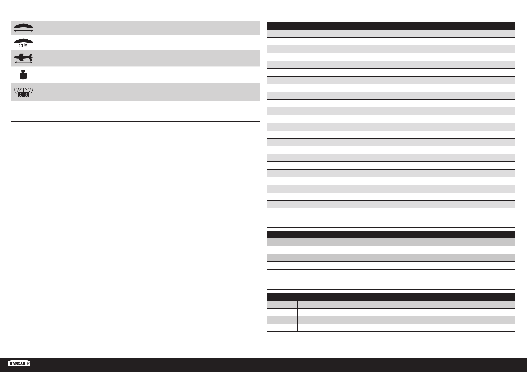
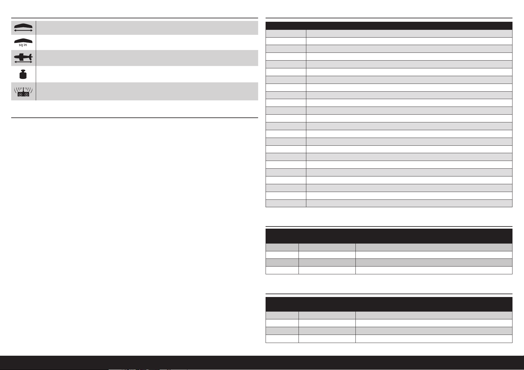
561/2 in (1435 mm)
537 sq in (35.65 dm2)
46.18 in (1172 mm)
79 oz (2240 g) without battery, 96 oz (2722 g) with recommended battery
5-channel (or greater)
TABLE OF CONTENTS
Specifi cations ...............................................................................................................................................................3
Replacement Parts ........................................................................................................................................................3
Required for Completion ...............................................................................................................................................3
Optional Parts ...............................................................................................................................................................3
Optional Batteries for High Power (When Using 12 x 6 Propeller) ...................................................................................4
Required Tools and Adhesives ....................................................................................................................................... 4
Optional Tools and Adhesives ........................................................................................................................................4
Building Precautions .....................................................................................................................................................4
Removing Wrinkles .......................................................................................................................................................4
Checking the Aileron Servos .........................................................................................................................................4
Landing Gear Installation ..............................................................................................................................................5
Joining the Wing Panels ................................................................................................................................................5
Stabilizer and Fin Installation ........................................................................................................................................5
Receiver Installation ...................................................................................................................................................... 7
Rudder and Elevator Servo Connections ........................................................................................................................7
Mounting the Cowling and Battery ................................................................................................................................7
Wing Installation ...........................................................................................................................................................8
Final Assembly ..............................................................................................................................................................8
Decal Installation ..........................................................................................................................................................8
Center of Gravity ...........................................................................................................................................................9
Pushrod Connections ....................................................................................................................................................9
Control Throws ...........................................................................................................................................................10
Prefl ight Checklist .......................................................................................................................................................10
Daily Flight Checks .....................................................................................................................................................10
Limited Warranty ........................................................................................................................................................11
Compliance Information for the European Union ..........................................................................................................12
Academy of Model Aeronautics National Model Aircraft Safety Code ............................................................................12
Part # Description
HAN318001 Fuselage
HAN318002 Wing Panels
HAN318003 Landing Gear
HAN318004 Horizontal Stabilizer
HAN318005 Vertical Stabilizer
HAN318006 Tailwheel Assembly
HAN318007 Tail Nut Cover
HAN318009 Pilot
HAN318010 Hatch w/Pilot
HAN318011 Cowl
HAN318012 Motor Box
HAN318013 Wheels
HAN318014 Pushrod Set
HAN318015 Wing Bolts
HAN318016 Hardware Set
HAN318017 Plastic Hardware
HAN318018 Decal Set
HAN318019 Landing Gear Covers
HAN318020 Propeller; 14 x 8.5
HAN338008 Wing Tube
SPMSA391 Standard Servo
SPMXAE1060C Avian 60 Amp Smart ESC 6S
SPMXAM2100 4250-600KV Motor
REQUIRED FOR COMPLETION
# Required Part # Description
2 SPMA3050 Standard Servo Extension 3-inch
1 SPMAR637T AR637T 6CH SAFE and AS3X TelemRX
1 SPMR6775 NX6 6 Ch Transmitter Only
1 SPMX50004S30 5000mAh 4S 14.8V Smart LiPo 30C IC5
OPTIONAL PARTS
# Required Part # Description
1 APC12060E Electric Propeller, 12 x 6E
1 APC14085E Electric Propeller, 14 x 8.5E
1 SPMAR8360T AR8360T 8CH SAFE Telemetry RX
1 SPMR8200 NX8 8 Ch DSMX Transmitter Only
Fun Scale PT-19 PNP
3 EN
Page 4
OPTIONAL BATTERIES FOR HIGH POWER (WHEN USING 12 X 6 PROPELLER) CHECKING THE AILERON SERVOS
# Required Part # Description
1 SPMX40006S30 4000mAh 6S 22.2V Smart 30C; IC5
1 SPMX50006S30 5000mAh 6S 22.2V Smart 30C; IC5
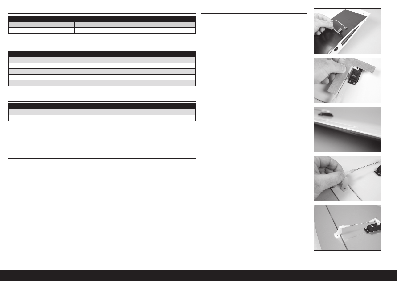
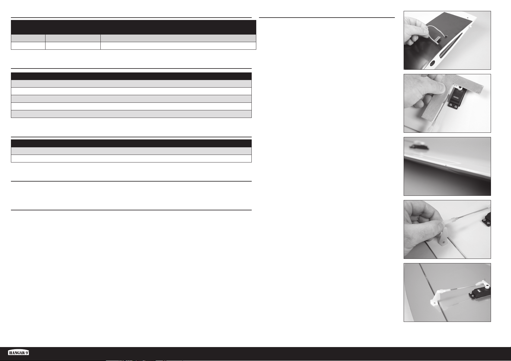
1. Pull the aileron servo leads through the holes in the top of the
wing.
REQUIRED TOOLS AND ADHESIVES
Description
Balancing stand
Flat-blade screwdriver
Nut driver: 1/4-inch
Phillips screwdriver: #1, #2
Square
2. Connect the aileron servo to the receiver. Center the aileron
stick and trim. Check that the pushrod is 90-degrees to the
servo arm. If not, either remove the servo arm and adjust, or
use the sub-trim when using a computer radio.
OPTIONAL TOOLS AND ADHESIVES
Description
Silicone Adhesive
Thin CA
BUILDING PRECAUTIONS
During assembly, we recommend resting the parts on a soft surface such as a soft towel to help prevent denting the
sheeting.
REMOVING WRINKLES
The covering of your model may develop wrinkles during shipping and will require the use of a heat gun (HAN100)
and covering glove (HAN150) or covering iron (HAN101) with a sealing iron sock (HAN141) to remove them. Use
caution while working around areas where the colors overlap to prevent separating the colors. Avoid using too much
heat, which could separate the colors. Placing a cool damp cloth on adjacent colors will also help in preventing the
separation of the colors while removing wrinkles.
3. Check the aileron to make sure it is aligned with the wing.
4. If the aileron is not aligned, disconnect the clevis and thread it
in or out to correct the alignment of the aileron.
5. Once adjusted, reconnect the clevis to the aileron control
horn. Slide the silicone retainer over the forks of the clevis to
prevent it from disconnecting from the control horn
Repeat this section for the remaining wing panel.
4EN
Page 5
LANDING GEAR INSTALLATION
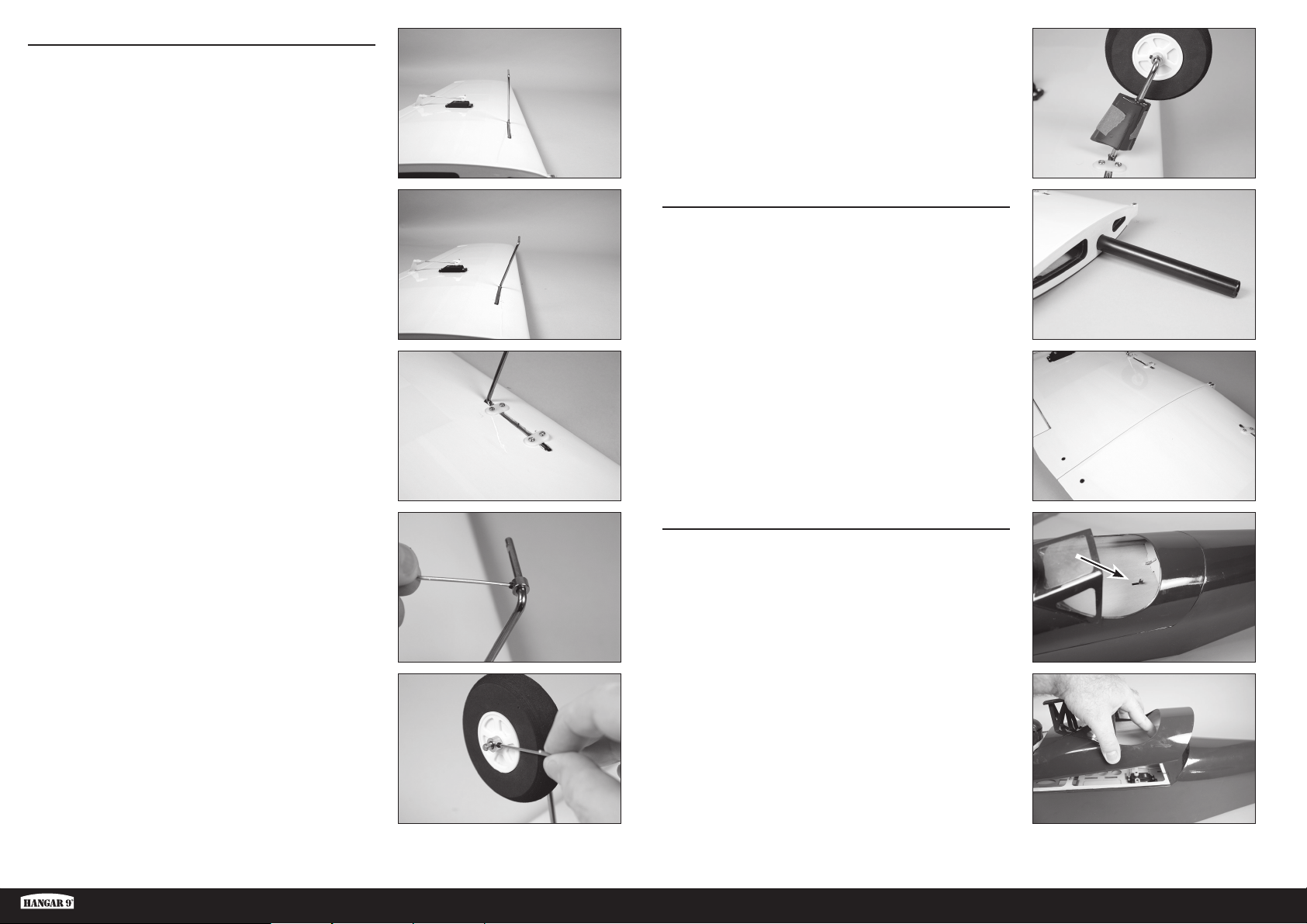
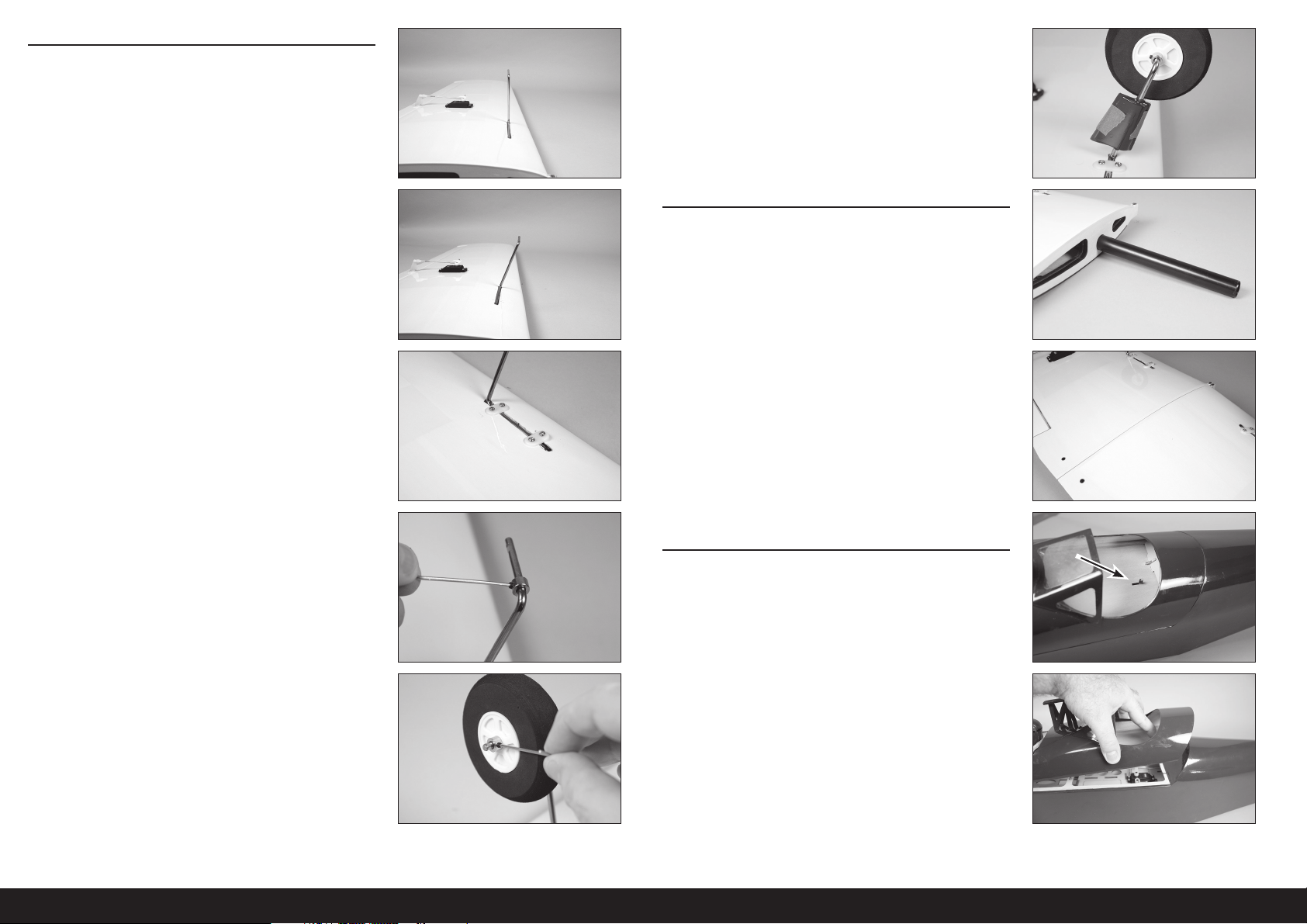
6. Fit the landing gear wire into the wing. The landing gear will
angle forward when installed correctly. The wire will be fl ush
with the bottom of the wing when installed.
Optional
10. Use a fl exible silicone adhesive to attach the landing gear
fairings to the landing gear. Use low-tack tape to hold the
fairings in position until the adhesive fully cures.
JOINING THE WING PANELS
7. Secure the landing gear uisng two nylon landing gear straps
and four 3mm x 12 self-tapping screws. Thread the screws
into the predrilled holes, then use a #2 Phillips screwdriver to
tighten the screws.
8. Slide a wheel collar on the landing gear. Thread an M3 x 4mm
setscrew into the wheel collar. Use the supplied hex wrench
to tighten the setscrew on the fl at area on the landing gear
nearest the vertical leg.
11. Slide the wing tube into the socket in the wing. It will slide in
easily, do not force it in farther than it will easily slide.
12. Slide the remaining wing panel on the wing tube. The wing
panels will fi t together tightly and with no gaps.
STABILIZER AND FIN INSTALLATION
13. Remove the canopy hatch from the fuselage by sliding the
latch located in the rear cockpit forward.
9. Slide the wheel on the landing gear, then secure it using a
wheel collar and M3 x 4mm setscrew.
Optional: Use a small amount of threadlock on
each setscrew to prevent them vibrating loose.
Fun Scale PT-19 PNP
14. Lift the hatch at the rear and remove it from the fuselage. Set
it aside in a safe location.
5 EN
Page 6
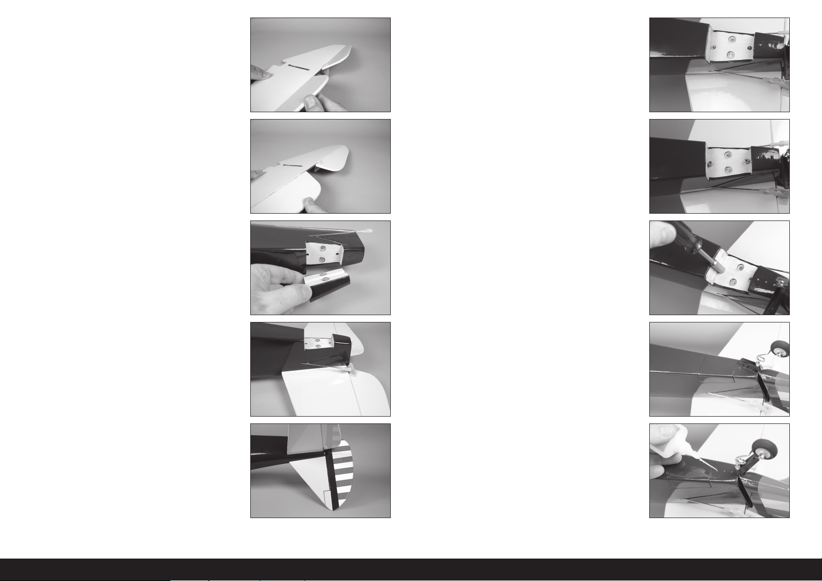
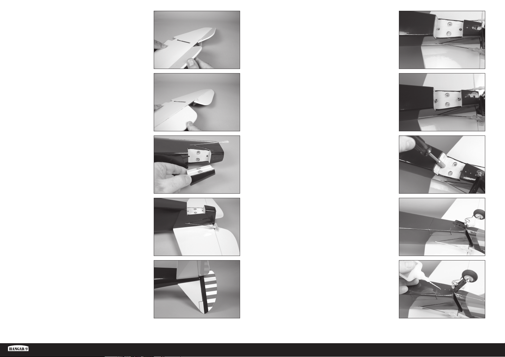
15. Flex the elevator through its range of motion a few times to
break in the hinges.
19. Slide one #4 washer on each of the threaded rods.
20. Thread the 4-40 nuts on the threaded rods.
16. Remove the magnetically-retained lower fuselage cover from
the fuselage. Set it aside in a safe location.
17. Slide the stabilizer into the slot in the fuselage. The control
horn will face the bottom of the fuselage. Make sure the
stabilizer is fully forward and the slot in the stabilizer aligned
with the slot in the fuselage for the fi n.
18. Break in the rudder hinges using the same method as the
elevator hinges. Slide the fi n into position. The tail wheel
bracket will require manipulation during the installation of
the fi n.
21. Use a 1/4-inch nut driver to tighten the nuts. Make sure not to
over-tighten the nuts which could damage the fuselage or fi n.
22. Place the lower fuselage cover back into position on the
fuselage.
Optional
23. Place a few drops of thin CA in each of the three holes for the
tail wheel bracket screws. Make sure the CA has fully cured
before proceeding.
6EN
Page 7
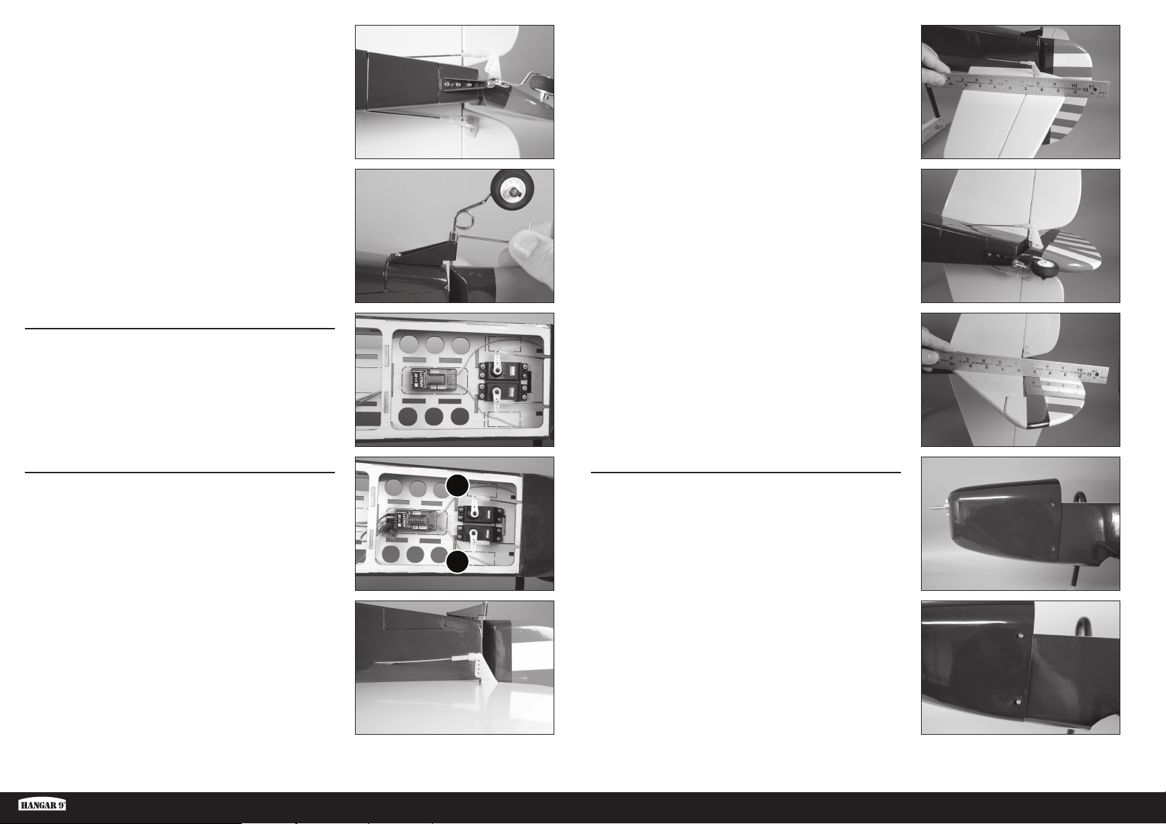
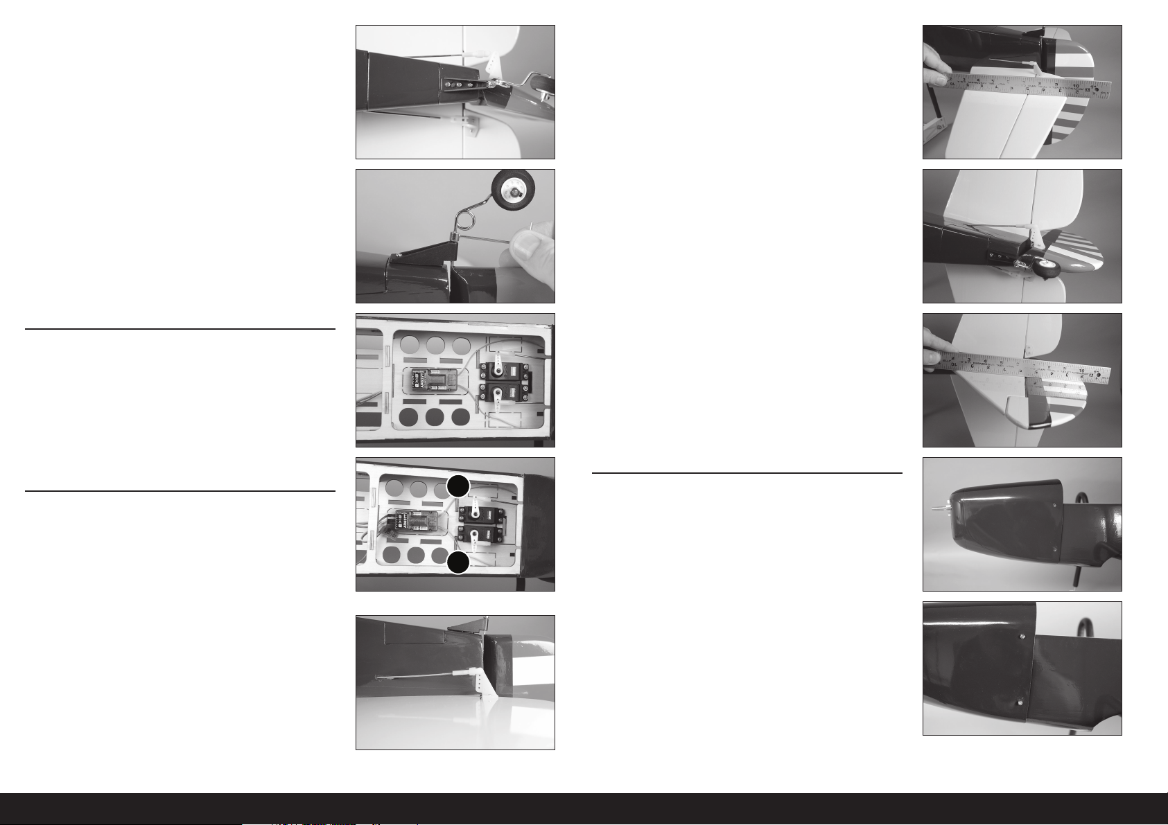
24. Use the three #2 x 5/16 inch sheet metal screws to secure
the tail wheel bracket to the fuselage. Use a #1 Phillips
screwdriver to tighten the screws.
29. Use a straight edge or ruler to check the alignment of the
elevator to the stabilizer. The ruler will lay fl at across both
when correctly aligned. Adjust the clevis on the pushrod as
necessary to align the elevator. Make sure to slide the silicone
retainer over the forks of the clevis to prevent it from coming
loose in fl ight.
25. Slide the wheel collar against the tail wheel bracket. Make
sure there is enough clearance that the rudder can move
freely. Tighten the setscrew in the wheel collar using a
1.5mm hex wrench.
RECEIVER INSTALLATION
26. Install the receiver in the fuselage using double-sided foam
tape. Refer to the receiver instructions for more details on
mounting the receiver and routing the antenna.
Use clear tape to secure the antenna so they don’t
interfere with the operation of the servos.
RUDDER AND ELEVATOR SERVO CONNECTIONS
27. Connect the rudder (1) and elevator (2) servos to the receiver.
Center the rudder and elevator sticks and trims. Check that
the pushrod is 90-degrees to the servo arm. If not, either
remove the servo arm and adjust, or use the sub-trim when
using a computer radio.
30. Connect the clevis to the outer hole of the rudder control horn.
31. Use a straight edge or ruler to check the alignment of the
rudder to the fi n. The ruler will lay fl at across both when
correctly aligned. Adjust the clevis on the pushrod as
necessary to align the rudder. Make sure to slide the silicone
retainer over the forks of the clevis to prevent it from coming
loose in fl ight.
MOUNTING THE COWLING AND BATTERY
1
2
32. Slide the cowling on the fuselage.
28. Connect the clevis to the outer hole of the elevator control
horn.
Fun Scale PT-19 PNP
33. Attach the cowl using four 3mm x 12mm self-tapping screws
and a #2 Phillips screwdriver. Two screws are used on each
side of the cowling.
7 EN
Page 8
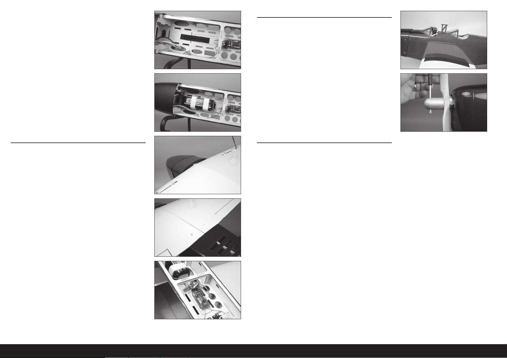
34. Apply one side of the hook and loop tape to the battery tray.
Optional: Apply a thin coat of thin CA on the
tray using a paper towel. Allow the CA to cure
before applying the hook and loop tape.
We recommend applying the hook portion of the hook and
loop tape to the airframe, and the loop portion to the battery.
FINAL ASSEMBLY
39. Install the canopy hatch on the fuselage.
35. Apply the mating side of the hook and loop tape on the
battery. Make sure not to cover any warning labels on the
battery. Place the battery in the fuselage, and use the hook
and loop strap to secure the battery.
The placement of the battery can be changed to
adjust the Center of Gravity. Once adjusted, mark the
location of the battery so it can be returned to the
correct location when installed after charging.
WING INSTALLATION
36. Slide the wing on the fuselage, aligning the tab on the wing
with the slot in the fuselage. The tab will fi t in the fuselage
with the leading edge tight against the fuselage.
37. Attach the wing to the fuselage using the two nylon wing
bolts. Tighten the bolts using a fl at blade screwdriver.
40. Slide the propeller on the motor shaft. Thread the spinner nut
on the motor shaft. Use a hex wrench passed through the
hole in the spinner nut to tighten the nut on the shaft.
Use extreme caution around the propeller once
installed. To prevent injury, treat the motor as ‘live’,
in that it could start abruptly without warning.
DECAL INSTALLATION
41. Apply the decals to your model using the box art photos as
a guide. Use a spray bottle and a drop of dish washing liquid
or glass cleaner sprayed in the location of the decal to allow
repositioning of the decal. Use a paper towel as a squeegee
to remove excess liquid from under the decal. Allow the
model to rest overnight so the remaining liquid can evaporate.
38. Connect the aileron servo leads to the receiver.
8EN
Page 9
CENTER OF GRAVITY
An important part of preparing the aircraft for fl ight is properly balancing the model.
1. Attach the wing to the fuselage. Make sure to connect the leads from the aileron to the appropriate leads from the
receiver. Make sure the leads are not exposed outside the fuselage before tightening the wing bolts. Your model
should be fl ight ready before balancing.
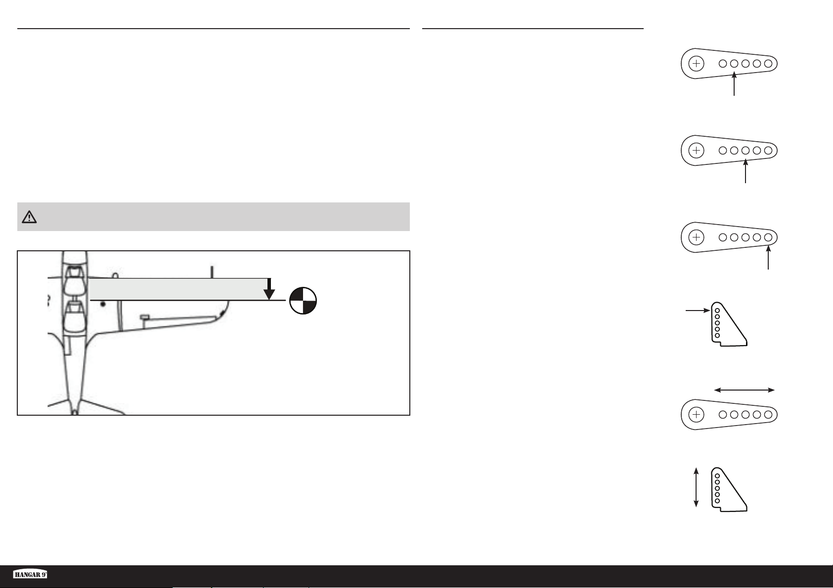
2. The recommended Center of Gravity (CG) location for your model is 85 mm behind the leading edge of the wing.
3. When balancing your model, make sure it is assembled and ready for fl ight. Support the plane inverted at the
marks made on the wing with your fi ngers, or a commercially available balancing stand.
The suggested Center of Gravity (CG) is the recommended balance point for fi rst fl ights. This provides a safe and stable
setting so you may comfortably explore the performance and handling of your model.
The CG Range of 80 mm to 95 mm is the extremes of balance to which the model was fl ight tested, and found to be
fl yable. The stability and performance of the model will vary when adjusted within this range. As each pilot’s fl ying style
and preferences are different, we suggest that you make small adjustments to the CG until you fi nd the feel that you
prefer.
CAUTION: You must adjust your aircraft’s center of gravity
and balance your model properly before attempting fl ights.
PUSHROD CONNECTIONS
Before checking the control throws, make sure the pushrods are
connected to the servo arms as shown to achieve the correct
amount of control throw.
Elevator
Ailerons
Rudder
85mm
back from leading
edge at the root
The clevis must be attached to the outer hole of the control horn
for the rudder, elevator and ailerons to achieve the correct amount
of control throw.
These are the recommended connections for the pushrod locations
for your fi rst fl ights. The pushrod locations can be changed
to increase or decrease the amount of throw once you are
comfortable with the fl ight characteristics of your model.
Control Horns
IncreaseDecrease
Decrease
Increase
Fun Scale PT-19 PNP
9 EN
Page 10
CONTROL THROWS
1. Turn on the transmitter and receiver of your model. Check the movement of the rudder using the transmitter.
When the stick is moved to the right, the rudder should also move right. Reverse the direction of the servo at the
transmitter if necessary.
2. Check the movement of the elevator with the radio system. Moving the elevator stick toward the bottom of the
transmitter will make the elevator move up.
3. Check the movement of the ailerons with the radio system. Moving the aileron stick to the right will make the
right aileron move up and the left aileron move down.
PREFLIGHT CHECKLIST
• Charge the transmitter, receiver and motor batteries. Follow the instructions provided with the charger. Follow all
manufacturer’s instructions for your electronic components.
• Check the radio installation and make sure all control surfaces (aileron, elevator, rudder, and fl aps) move correctly
(i.e., the correct direction and with the recommended throws).
• Check all the hardware (control horns, servo horns, and clevises) to make sure they are secure and in good condition.
• Prior to each fl ying session (and especially with a new model), perform a range check of your radio system. See your
radio manual for the recommended range and instructions for your particular radio system.
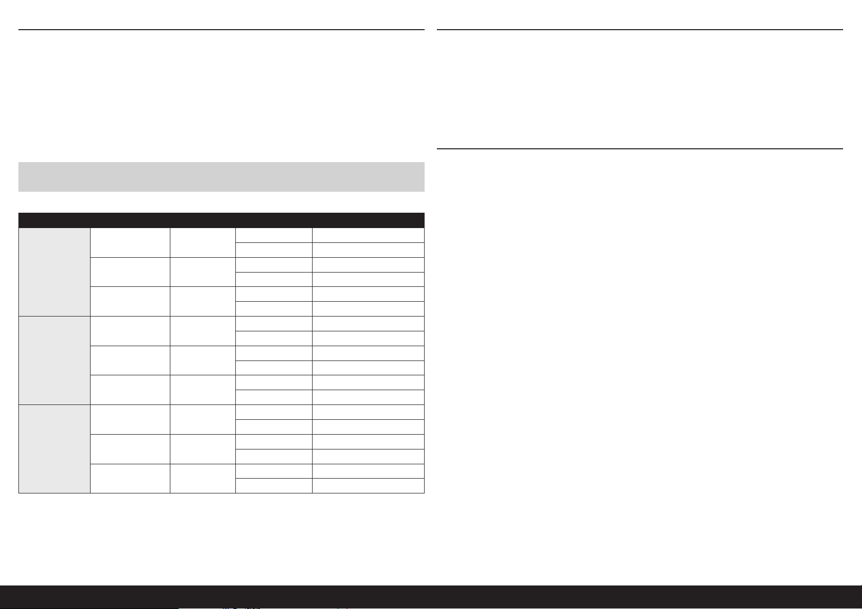
4. Use a ruler to adjust the throw of the elevator, ailerons and rudder.
PLEASE DO NOT INCREASE CONTROL MOVEMENTS FROM THOSE SHOWN BEFORE FIRST FLIGHT! This model is very
responsive to pitch and roll with small movements.
Surface Rate Exponential Direction Throw
Up 13 mm
Down 13 mm
Up 9 mm
Down 9 mm
Up 7 mm
Down 7 mm
Up 15 mm
Down 15 mm
Up 10.5 mm
Down 10.5 mm
Up 8 mm
Down 8 mm
Left 36 mm
Right 36 mm
Left 24 mm
Right 24 mm
Left 18 mm
Right 18 mm
Aileron
Elevator
Rudder
High 10%
Mid 5%
Low 0%
High 10%
Mid 5%
Low 0%
High 10%
Mid 5%
Low 0%
DAILY FLIGHT CHECKS
• Check the battery voltage of the transmitter battery. Do not fl y below the manufacturer’s recommended voltage.
Doing so can cause your aircraft to crash.
• Check all hardware (linkages, screws, nuts, and bolts) prior to each day’s fl ight. Ensure that binding does not occur
and that all parts are properly secured.
• Ensure all surfaces are moving in the proper manner.
• Perform a ground range check before each day’s fl ying session.
• All servo leads and switch harness plugs should be secured in the receiver.
10EN
Page 11

LIMITED WARRANTY
What this Warranty Covers
Horizon Hobby, LLC, (Horizon) warrants to the original purchaser that the product purchased (the “Product”) will be free from
defects in materials and workmanship at the date of purchase.
What is Not Covered
This warranty is not transferable and does not cover (i) cosmetic damage, (ii) damage due to acts of God, accident, misuse,
abuse, negligence, commercial use, or due to improper use, installation, operation or maintenance, (iii) modifi cation of or to
any part of the Product, (iv) attempted service by anyone other than a Horizon Hobby authorized service center, (v) Product
not purchased from an authorized Horizon dealer, (vi) Product not compliant with applicable technical regulations, or (vii) use
that violates any applicable laws, rules, or regulations.
OTHER THAN THE EXPRESS WARRANTY ABOVE, HORIZON MAKES NO OTHER WARRANTY OR REPRESENTATION,
AND HEREBY DISCLAIMS ANY AND ALL IMPLIED WARRANTIES, INCLUDING, WITHOUT LIMITATION, THE IMPLIED
WARRANTIES OF NON-INFRINGEMENT, MERCHANTABILITY AND FITNESS FOR A PARTICULAR PURPOSE. THE PURCHASER
ACKNOWLEDGES THAT THEY ALONE HAVE DETERMINED THAT THE PRODUCT WILL SUITABLY MEET THE REQUIREMENTS
OF THE PURCHASER’S INTENDED USE.
Purchaser’s Remedy
Horizon’s sole obligation and purchaser’s sole and exclusive remedy shall be that Horizon will, at its option, either (i) service,
or (ii) replace, any Product determined by Horizon to be defective. Horizon reserves the right to inspect any and all Product(s)
involved in a warranty claim. Service or replacement decisions are at the sole discretion of Horizon. Proof of purchase is
required for all warranty claims. SERVICE OR REPLACEMENT AS PROVIDED UNDER THIS WARRANTY IS THE PURCHASER’S
SOLE AND EXCLUSIVE REMEDY.
Limitation of Liability
HORIZON SHALL NOT BE LIABLE FOR SPECIAL, INDIRECT, INCIDENTAL OR CONSEQUENTIAL DAMAGES, LOSS OF PROFITS
OR PRODUCTION OR COMMERCIAL LOSS IN ANY WAY, REGARDLESS OF WHETHER SUCH CLAIM IS BASED IN CONTRACT,
WARRANTY, TORT, NEGLIGENCE, STRICT LIABILITY OR ANY OTHER THEORY OF LIABILITY, EVEN IF HORIZON HAS BEEN
ADVISED OF THE POSSIBILITY OF SUCH DAMAGES. Further, in no event shall the liability of Horizon exceed the individual price
of the Product on which liability is asserted. As Horizon has no control over use, setup, fi nal assembly, modifi cation or misuse,
no liability shall be assumed nor accepted for any resulting damage or injury. By the act of use, setup or assembly, the user
accepts all resulting liability. If you as the purchaser or user are not prepared to accept the liability associated with the use of
the Product, purchaser is advised to return the Product immediately in new and unused condition to the place of purchase.
Law
These terms are governed by Illinois law (without regard to confl ict of law principals). This warranty gives you specifi c legal
rights, and you may also have other rights which vary from state to state. Horizon reserves the right to change or modify this
warranty at any time without notice.
WARRANTY SERVICES
Questions, Assistance, and Services
Your local hobby store and/or place of purchase cannot provide warranty support or service. Once assembly, setup or
use of the Product has been started, you must contact your local distributor or Horizon directly. This will enable Horizon to
better answer your questions and service you in the event that you may need any assistance. For questions or assistance,
please visit our website at www.horizonhobby.com, submit a Product Support Inquiry, or call the toll free telephone number
referenced in the Warranty and Service Contact Information section to speak with a Product Support representative.
Inspection or Services
If this Product needs to be inspected or serviced and is compliant in the country you live and use the Product in, please use
the Horizon Online Service Request submission process found on our website or call Horizon to obtain a Return Merchandise
Authorization (RMA) number. Pack the Product securely using a shipping carton. Please note that original boxes may be
included, but are not designed to withstand the rigors of shipping without additional protection. Ship via a carrier that
provides tracking and insurance for lost or damaged parcels, as Horizon is not responsible for merchandise until it arrives
and is accepted at our facility. An Online Service Request is available at http://www.horizonhobby.com/content/servicecenter_render-service-center. If you do not have internet access, please contact Horizon Product Support to obtain a RMA
number along with instructions for submitting your product for service. When calling Horizon, you will be asked to provide
your complete name, street address, email address and phone number where you can be reached during business hours.
When sending product into Horizon, please include your RMA number, a list of the included items, and a brief summary of
the problem. A copy of your original sales receipt must be included for warranty consideration. Be sure your name, address,
and RMA number are clearly written on the outside of the shipping carton.
NOTICE: Do not ship LiPo batteries to Horizon. If you have any issue with a LiPo battery, please contact the
appropriate Horizon Product Support offi ce.
Warranty Requirements
For Warranty consideration, you must include your original sales receipt verifying the proof-of-purchase date. Provided
warranty conditions have been met, your Product will be serviced or replaced free of charge. Service or replacement
decisions are at the sole discretion of Horizon.
Non-Warranty Service
Should your service not be covered by warranty, service will be completed and payment will be required without notifi cation or
estimate of the expense unless the expense exceeds 50% of the retail purchase cost. By submitting the item for service you
are agreeing to payment of the service without notifi cation. Service estimates are available upon request. You must include this
request with your item submitted for service. Non-warranty service estimates will be billed a minimum of ½ hour of labor. In
addition you will be billed for return freight. Horizon accepts money orders and cashier’s checks, as well as Visa, MasterCard,
American Express, and Discover cards. By submitting any item to Horizon for service, you are agreeing to Horizon’s Terms and
Conditions found on our website http://www.horizonhobby.com/content/service-center_render-service-center.
Fun Scale PT-19 PNP
ATTENTION: Horizon service is limited to Product compliant in the country of use and ownership. If received,
a non-compliant Product will not be serviced. Further, the sender will be responsible for arranging return
shipment of the un-serviced Product, through a carrier of the sender’s choice and at the sender’s expense.
Horizon will hold non-compliant Product for a period of 60 days from notifi cation, after which it will be
discarded.
10/15
11 EN
Page 12
Country of
Purchase
United States
of America
European
Union
Horizon Hobby Contact Information Address
Horizon Service Center
(Repairs and Repair
Requests)
Horizon Product Support
(Product Technical
Assistance)
Sales
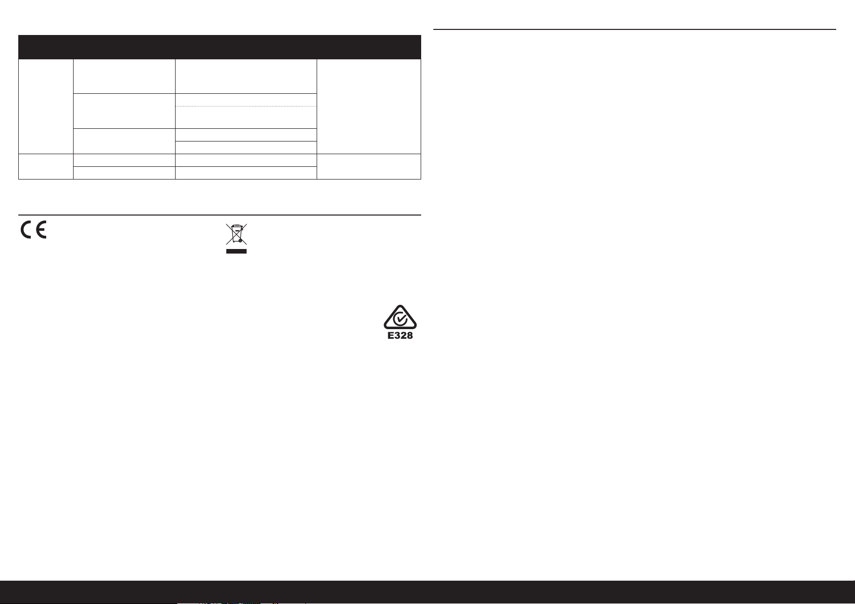
Horizon Technischer Service [email protected]
Sales: Horizon Hobby GmbH +49 (0) 4121 2655 100
servicecenter.horizonhobby.com/
RequestForm/
877-504-0233
[email protected]
800-338-4639
COMPLIANCE INFORMATION FOR THE EUROPEAN UNION
EU Compliance Statement: Hereby, Horizon
Hobby, LLC declares that the device is in
compliance with the following:
2014/30/EU EMC Directive
RoHS 2 Directive 2011/65/EU;
RoHS 3 Directive - Amending 2011/65/EU Annex II
2015/863
The full text of the EU declaration of conformity is
available at the following internet address: https://www.
horizonhobby.com/content/support-render-compliance.
EU Manufacturer of Record:
Horizon Hobby, LLC
2904 Research Road
Champaign, IL 61822 USA
EU Importer of Record:
Horizon Hobby, GmbH
Hanskampring 9
22885 Barsbüttel Germany
(WEEE). This label indicates that this product should
not be disposed of with household waste. It should be
deposited at an appropriate facility to enable recovery and
recycling.
2904 Research Road
Champaign, IL 61822
Hanskampring 9
D 22885 Barsbüttel, Germany
WEEE NOTICE:
This appliance is labeled in accordance with
European Directive 2012/19/EU concerning
waste of electrical and electronic equipment
ACADEMY OF MODEL AERONAUTICS NATIONAL MODEL AIRCRAFT SAFETY CODE
Effective January 1, 2018
A model aircraft is a non-human-carrying device capable of sustained fl ight within visual line of sight of the
pilot or spotter(s). It may not exceed limitations of this code and is intended exclusively for sport, recreation,
education and/or competition. All model fl ights must be conducted in accordance with this safety code and
related AMA guidelines, any additional rules specifi c to the fl ying site, as well as all applicable laws and
regulations.
As an AMA member I agree:
• I will not fl y a model aircraft in a careless or reckless manner.
• I will not interfere with and will yield the right of way to all human-carrying aircraft using AMA’s See and Avoid
Guidance and a spotter when appropriate.
• I will not operate any model aircraft while I am under the infl uence of alcohol or any drug that could adversely affect
my ability to safely control the model.
• I will avoid fl ying directly over unprotected people, moving vehicles, and occupied structures.
• I will fl y Free Flight (FF) and Control Line (CL) models in compliance with AMA’s safety programming.
• I will maintain visual contact of an RC model aircraft without enhancement other than corrective lenses prescribed to
me. When using an advanced fl ight system, such as an autopilot, or fl ying First-Person View (FPV), I will comply with
AMA’s Advanced Flight System programming.
• I will only fl y models weighing more than 55 pounds, including fuel, if certifi ed through AMA’s Large Model Airplane
Program.
• I will only fl y a turbine-powered model aircraft in compliance with AMA’s Gas Turbine Program.
• I will not fl y a powered model outdoors closer than 25 feet to any individual, except for myself or my helper(s)
located at the fl ightline, unless I am taking off and landing, or as otherwise provided in AMA’s Competition
Regulation.
• I will use an established safety line to separate all model aircraft operations from spectators and bystanders.
For a complete copy of AMA’s Safety Handbook please visit:
www.modelaircraft.org/fi les/100.pdf
12EN
Page 13
HINWEIS
Alle Anweisungen, Garantien und andere Begleitdokumente können von Horizon Hobby, LLC nach eigenem Ermessen
geändert werden. Um aktuelle Produktinformationen zu erhalten, besuchen Sie horizonhobby.com oder www.
towerhobbies.com und klicken Sie auf die Registerkarte Support oder Ressourcen für dieses Produkt.
SPEZIELLE BEDEUTUNGEN
Die folgenden Begriffe werden in der gesamten Produktliteratur verwendet, um auf unterschiedlich hohe
Gefahrenrisiken beim Betrieb dieses Produkts hinzuweisen:
WARNUNG: Wenn diese Verfahren nicht korrekt befolgt werden, ergeben sich wahrscheinlich Sachschäden,
Kollateralschäden und schwere Verletzungen ODER mit hoher Wahrscheinlichkeit oberfl ächliche Verletzungen.
ACHTUNG: Wenn diese Verfahren nicht korrekt befolgt werden, ergeben sich wahrscheinlich Sachschäden UND die
Gefahr von schweren Verletzungen.
HINWEIS: Wenn diese Verfahren nicht korrekt befolgt werden, können sich möglicherweise Sachschäden UND
geringe oder keine Gefahr von Verletzungen ergeben.
WARNUNG: Lesen Sie die GESAMTE Bedienungsanleitung, um sich vor dem Betrieb mit den Produktfunktionen
vertraut zu machen. Wird das Produkt nicht korrekt betrieben, kann dies zu Schäden am Produkt oder persönlichem
Eigentum führen oder schwere Verletzungen verursachen.
Dies ist ein hochentwickeltes Hobby-Produkt. Es muss mit Vorsicht und gesundem Menschenverstand betrieben
werden und benötigt gewisse mechanische Grundfähigkeiten. Wird dieses Produkt nicht auf eine sichere und
verantwortungsvolle Weise betrieben, kann dies zu Verletzungen oder Schäden am Produkt oder anderen Sachwerten
führen. Dieses Produkt eignet sich nicht für die Verwendung durch Kinder ohne direkte Überwachung eines
Erwachsenen. Verwenden Sie das Produkt nicht mit inkompatiblen Komponenten oder verändern es in jedweder Art
ausserhalb der von Horizon Hobby, LLC vorgegebenen Anweisungen. Diese Bedienungsanleitung enthält Anweisungen
für Sicherheit, Betrieb und Wartung. Es ist unbedingt notwendig, vor Zusammenbau, Einrichtung oder Verwendung
alle Anweisungen und Warnhinweise im Handbuch zu lesen und zu befolgen, damit es bestimmungsgemäß betrieben
werden kann und Schäden oder schwere Verletzungen vermieden werden.
Nicht geeignet für Kinder unter 14 Jahren. Dies ist kein Spielzeug.
WARNUNGEN UND SICHERHEITS-VORKEHRUNGEN
Bitte lesen und befolgen Sie alle Anweisungen und Sicherheitsvorkehrungen vor dem Gebrauch. Falscher, nicht
sachgemäßer Gebrauch kann Feuer, ernsthafte Verletzungen und Sachbeschädigungen zur Folge haben.
Komponenten
Verwenden Sie mit dem Produkt nur kompatible Komponenten. Sollten Fragen zur Kompatibilität auftreten, lesen Sie
bitte die Produkt- oder Bedienungsanweisung oder kontaktieren den Service von Horizon Hobby.
Fliegen
Fliegen Sie um Sicherheit garantieren zu können, nur in weiten offenen Gegenden. Wir empfehlen hier den Betrieb auf
zugelassenen Modellfl ugplätzen. Bitte beachten Sie lokale Vorschriften und Gesetze, bevor Sie einen Platz zum Fliegen
wählen.
Propeller
Halten Sie lose Gegenstände, die sich im Propeller verfangen können, immer vom Propeller fern. Dazu gehören lose
Kleidung oder andere Gegenstände wie Stifte und Schraubendreher. Halten Sie Ihre Hände vom Propeller fern, da es zu
Verletzungen kommen kann.
Akkus
Folgen Sie immer den Herstelleranweisungen bei dem Gebrauch oder Entsorgung von Akkus. Falsche Behandlung von
LiPo Akkus kann zu Feuer mit Körperverletzungen und Sachbeschädigung führen.
Kleinteile
Dieser Baukasten beinhaltet Kleinteile und darf nicht unbeobachtet in der Nähe von Kindern gelassen werden, da die
Teile verschluckt werden könnten mit ernsthaften Verletzung zur Folge.
EMPFEHLUNGEN ZUM SICHEREN BETRIEB
• Überprüfen Sie zur Flugtauglichkeit ihr Modell vor jedem Flug.
• Beachten Sie andere Piloten deren Sendefrequenzen ihre Frequenz stören könnte.
• Begegnen Sie anderen Piloten in ihrem Fluggebiet immer höfl ich und respektvoll.
• Wählen Sie ein Fluggebiet, dass frei von Hindernissen und groß genug ist.
• Stellen Sie vor dem Start sicher, dass die Fläche frei von Freunden und Zuschauern ist.
• Beobachten Sie den Luftraum und andere Flugzeuge/Objekte die ihren Flugweg kreuzen und zu einem Konfl ikt
führen könnten.
• Planen Sie sorgfältig ihren Flugweg vor dem Start.
VOR DEM ZUSAMMENBAU
• Entnehmen Sie zur Überprüfung jedes Teil der Verpackung.
• Überprüfen Sie den Rumpf, Tragfl ächen, Seiten- und Höhenruder auf Beschädigung.
• Sollten Sie beschädigte oder fehlende Teile feststellen, kontaktieren Sie bitte den Verkäufer.
• Laden des Senders und Empfängers.
• Zentrieren der Trimmungen und Sticks auf dem Sender.
• Sollten Sie einen Computersender verwenden, resetten Sie einen Speicherplatz und benennen ihn nach dem Modell.
• Sender und Empfänger jetzt nach den Bindeanweisung des Herstellers zu binden.
HINWEIS: Das Funksystem nach dem Einstellen der Ruderausschläge erneut binden. Damit wird verhindert, dass sich
die Servos auf ihre Endpunkte bewegen, ehe Sender und Empfänger verbunden sind. Außerdem wird garantiert, dass
die Servo-Umkehreinstellungen im Funksystem gespeichert werden.
Fun Scale PT-19 PNP
13 DE
Page 14
ERSATZTEILESPEZIFIKATIONEN
561/2 in (1435 mm)
537 sq in (35.65 dm2)
46.18 in (1173 mm)
55 oz (1569 g) ohne Akku, 73 oz (2079 g) mit empfohlenem Akku
5-Kanal (oder mehr)
INHALTSVERZEICHNIS
Warnungen und Sicherheits-vorkehrungen .................................................................................................................13
Empfehlungen zum sicheren Betrieb ...........................................................................................................................13
Vor dem Zusammenbau ..............................................................................................................................................13
Spezifi kationen ...........................................................................................................................................................14
Ersatzteile ...................................................................................................................................................................14
Zur Fertigstellung erforderlich .....................................................................................................................................14
Optionale Teile ............................................................................................................................................................14
Optionale Akkus für Hochleistung (bei Verwendung eines 12 x 6 Propeller)..................................................................15
Erforderliche Werkzeuge und Klebstoffe ......................................................................................................................15
Optionale Werkzeuge und Klebstoffe ...........................................................................................................................15
Vorsichtsmaßnahmen beim Zusammenbau .................................................................................................................15
Falten entfernen .........................................................................................................................................................15
Querruder-Servos prüfen ............................................................................................................................................15
Montage des Fahrwerks .............................................................................................................................................16
Tragfl ächen zusammenfügen ......................................................................................................................................16
Montage von Stabilisator und Seitenleitwerk ...............................................................................................................16
Montage des Empfängers ...........................................................................................................................................18
Servo-Anschlüsse der Seiten- und Höhenruder ...........................................................................................................18
Motorhaube und Akku befestigen ................................................................................................................................ 18
Montage der Tragfl äche ..............................................................................................................................................19
Abschließende Montage ..............................................................................................................................................19
Anbringen der Decals..................................................................................................................................................19
Der Schwerpunkt ........................................................................................................................................................20
Gestängeanschlüsse ...................................................................................................................................................20
Ruderausschlag ..........................................................................................................................................................21
Vorfl ugkontrolle ..........................................................................................................................................................21
Täglicher Flug Check .................................................................................................................................................21
Garantie Und Service Informationen ............................................................................................................................22
Garantie und Service Kontaktinformationen.................................................................................................................23
Teile-Nr. Beschreibung
HAN318001 Rumpf
HAN318002 Tragfl ächen
HAN318003 Fahrwerk Set
HAN318004 Höhenruder
HAN318005 Seitenleitwerk
HAN318006 Spornrad m. Zbh.
HAN318007 Heckmutterabdeckung
HAN318009 Pilotenfi gur
HAN318010 Kanzel mit Pilot
HAN318011 Motorhaube
HAN318012 Motorkasten
HAN318013 Räder
HAN318014 Gestänge / Anlenkungen Set
HAN318015 Flügelschrauben
HAN318016 Kleinteile Set
HAN318017 Kunststoff-Hardware
HAN318018 Dekorbogen
HAN318019 Fahrwerkabdeckungen
HAN318020 Propeller, 14 x 8,5
HAN338008 Tragfl ächenverbinder
SPMSA391 Servoarm-Satz
SPMXAE1060C Avian 60A Smart-Geschwindigkeitsregler 6S
SPMXAM2100 4250-600KV Motor 14-polig
ZUR FERTIGSTELLUNG ERFORDERLICH
Erforderliche
Anz.
2 SPMA3050 Standard Servoverlängerung 76mm (3 Zoll)
1 SPMAR637T AR637T SAFE mit 6Kanälen und AS3X-Telemetrieempfänger
1 SPMR6775 Nur NX6 6-Kanal-Sender
1 SPMX50004S30 5000mAh 4S 14,8V Smart LiPo 30C; IC5
Teile-Nr. Beschreibung
OPTIONALE TEILE
Erforderliche
Anz.
1 APC12060E Elektro Propeller, 12 x 6
1 APC14085E Elektro Propeller, 14 x 8,5
1 SPMAR8360T AR8360T SAFE-Telemetrieempfänger mit 8 Kanälen
1
Teile-Nr. Beschreibung
SPMR8200 Nur NX8 8-Kanal-DSMX-Sender
14DE
Page 15
OPTIONALE AKKUS FÜR HOCHLEISTUNG (BEI VERWENDUNG EINES 12 X 6 PROPELLER) QUERRUDER-SERVOS PRÜFEN
Erforderliche
Anz.
1 SPMX40006S30 4000mAh 6S 22,2V Smart LiPo 30C; IC5
1 SPMX50006S30 5000mAh 6S 22,2V Smart LiPo 30C; IC5
Teile-Nr. Beschreibung
1. Die Leitungen des Querruder-Servos durch die Löcher in der
Oberseite des Flügels führen.
ERFORDERLICHE WERKZEUGE UND KLEBSTOFFE
Beschreibung
Balancierständer
Schraubendreher fl ach
Steckschlüssel. 1/4 inch
Phillips Schraubendreher: #1,#2
Winkel
OPTIONALE WERKZEUGE UND KLEBSTOFFE
Beschreibung
Silikonklebstoff
Sekundenkleber dünnfl üssig
VORSICHTSMASSNAHMEN BEIM ZUSAMMENBAU
Während des Zusammenbaus empfehlen wird, dass die Teile auf einer weichen Oberfl äche, wie einem Handtuch,
abgelegt werden, um ein Eindrücken der Bleche zu verhindern.
FALTEN ENTFERNEN
Beim Versand können an der Abdeckung Ihres Modells Falten entstehen. Um diese zu entfernen, benötigen Sie
eine Heißluftpistole (HAN100) und einen Schutzhandschuh (HAN150) oder ein Heißsiegelgerät (HAN101) mit einem
Folienbügeleisen-Schutzbezug (HAN141). Seien Sie vorsichtig, wenn Sie um Bereiche herum arbeiten, in denen sich die
Farben überschneiden, um zu vermeiden, dass die Farben sich trennen. Indem Sie zu hohe Temperaturen vermeiden,
beugen Sie einer Trennung der Farben vor. Um eine Trennung der Farben während des Entfernens der Falten zu
verhindern, hilft außerdem das Aufl egen eines kühlen, feuchten Tuches auf angrenzende Farben.
2. Querruder-Servo mit dem Empfänger verbinden. Hebel des
Querruders zentrieren und trimmen. Überprüfen, dass das
Gestänge im Winkel von 90Grad zum Servoarm liegt. Falls
nicht, entweder den Servoarm entfernen und anpassen oder
die Ersatztrimmung bei Einsatz eines Computer-Funksystems
verwenden.
3. Das Querruder kontrollieren, um sicherzustellen, dass es am
Flügel ausgerichtet ist.
4. Ist das Querruder nicht korrekt ausgerichtet, den Gabelkopf
entfernen und hinein- oder herausdrehen, um die Ausrichtung
des Querruders zu korrigieren.
Fun Scale PT-19 PNP
5. Nach erfolgter Anpassung den Gabelkopf wieder am
Steuerhorn des Querruders befestigen. Den Silikon-Halter
über die Zinken des Gabelkopfes schieben, um zu verhindern,
dass sich dieser vom Steuerhorn löst.
Wiederholen Sie diesen Vorgang für
die verbleibende Tragfläche.
15 DE
Page 16
MONTAGE DES FAHRWERKS
6. Das Kabel des Fahrwerks in den Flügel einpassen. Wenn es
korrekt montiert ist, neigt sich das Fahrwerk nach vorne. Das
Kabel wird bündig mit dem Flügelboden abschließen wenn es
installiert ist.
Optional
11. Mit einem fl exiblen Silikonklebstoff die
Fahrwerkverkleidungen am Fahrwerk befestigen. Mit einem
Klebeband mit geringer Klebekraft die Fahrwerkverkleidungen
in Position halten, bis der Klebstoff vollständig ausgehärtet ist.
TRAGFLÄCHEN ZUSAMMENFÜGEN
8. Sichern Sie das Fahrwerk mit zwei Fahrwerk-Halteriemen aus
Nylon und vier 3mm x 12 Blechschrauben. Schrauben Sie die
Schrauben in die vorgebohrten Löcher ein und befestigen Sie
sie mit einem Kreuzschlitzschraubendreher.
9. Eine Anschlaghülse auf das Fahrwerk schieben. Schrauben
Sie eine M3 x 4mm Feststellschraube in die Anschlaghülse.
Verwenden Sie den mitgelieferten Sechskantschlüssel zum
Anziehen der Feststellschraube auf dem fl achen Bereich des
Fahrwerks, möglichst nahe am vertikalen Fahrwerkbein.
12. Das Flügelrohr in die Lasche des Flügels schieben. Es lässt
sich leicht einführen. Daher nicht mehr Kraft aufwenden, als
beim leichten Einschieben notwendig.
13. Die verbleibende Tragfl äche auf das Flügelrohr schieben. Die
Tragfl ächen sitzen fest und spaltfrei.
MONTAGE VON STABILISATOR UND
SEITENLEITWERK
14. Durch Vorwärtsschieben des Riegels hinten im Cockpit die
Kanzelabdeckung vom Rumpf entfernen.
10. Schieben Sie das Rad auf das Fahrwerk und sichern es
danach mit einer Anschlaghülse und einer M3 x 4mm
Feststellschraube.
Optional: Eine kleine Menge Gewindekleber
auf jeder Feststellschraube verwenden, um ein
Lösen unter Vibrationen zu verhindern.
15. Die Kanzelabdeckung hinten anheben und vom Rumpf
entfernen. An einem sicheren Ort ablegen.
16DE
Page 17
16. Das Höhenruder einige Male durch seinen Bewegungsradius
biegen, um die Aufhängungen einzufahren.
21. Eine Nr.4 Unterlegscheibe auf jede der Gewindestangen
schieben.
22. Die 4-40 Muttern auf die Gewindestange drehen.
18. Die magnetisch gesicherte untere Rumpfabdeckung vom
Rumpf entfernen. An einem sicheren Ort ablegen.
19. Den Stabilisator in den Schlitz am Rumpf schieben.
Das Steuerhorn zeigt auf die Unterseite des Rumpfes.
Sicherstellen, dass sich der Stabilisator ganz vorne befi ndet
und dass der Schlitz im Stabilisator mit dem Schlitz im Rumpf
für das Seitenleitwerk ausgerichtet ist.
20. Die Seitenruderaufhängungen einfahren, dabei wie bei
den Höhenrudern vorgehen. Das Seitenleitwerk in Position
schieben. Die Spornradhalterung muss während der Montage
des Seitenleitwerks verstellt werden.
23. Mit einem 6mm (1/4Zoll) Steckschlüssel die Muttern
festziehen. Die Muttern nicht zu stark anziehen, wodurch
Rumpf oder Seitenleitwerk beschädigt werden könnten.
24. Die untere Rumpfabdeckung wieder in Position auf dem
Rumpf positionieren.
Optional
25. Einige Tropfen dünnen CA-Klebstoff in jedes der drei Löcher
für die Spornradhalterungsschrauben geben. Sicherstellen,
dass der CA-Klebstoff vor dem Fortfahren vollständig
ausgehärtet ist.
Fun Scale PT-19 PNP
17 DE
Page 18
26. Mithilfe von drei #2 x 7,5mm (5/16Zoll) Metallschrauben
die Spornradhalterung am Rumpf befestigen. Mit einem
Kreuzschlitzschraubendreher Nr.1 die Schrauben festziehen.
31. Mit einem Geodreieck oder Lineal die Ausrichtung des
Höhenruders auf dem Stabilisator prüfen. Das Lineal liegt
nach korrekter Ausrichtung fl ach über beiden. Den Gabelkopf
bei Bedarf an das Gestänge anpassen, um das Höhenruder
auszurichten. Den Silikon-Halter über die Zinken des
Gabelkopfes schieben, um zu verhindern, dass sich dieser
beim Flug löst.
27. Die Anschlaghülse gegen die Spornradhalterung schieben.
Sicherstellen, das genügend Spielraum vorhanden ist,
damit sich das Seitenruder frei bewegen kann. Die
Feststellschraube in der Anschlaghülse mit einem 1,5mm
Sechskant sichern.
MONTAGE DES EMPFÄNGERS
28. Den Empfänger im Rumpf mit doppelseitigem
Schaumklebeband befestigen. Weitere Informationen zur
Montage des Empfängers und Führung der Antenne sind der
Empfängeranleitung zu entnehmen.
Mit Klarsichtklebeband die Antenne sichern, damit sie
den Betrieb des Servos nicht beeinträchtigen kann.
SERVO-ANSCHLÜSSE DER SEITEN- UND
HÖHENRUDER
29. Die Servos von Seitenruder (1) und Höhenruder (2) mit dem
Empfänger verbinden. Seitenruder, Höhenruder-Hebel und
Trimmungen zentrieren. Überprüfen, dass das Gestänge
im Winkel von 90Grad zum Servoarm liegt. Falls nicht,
entweder den Servoarm entfernen und anpassen oder die
Ersatztrimmung bei Einsatz eines Computer-Funksystems
verwenden.
30. Den Gabelkopf mit dem Außenloch des Höhenruder-
Steuerhorns verbinden.
32. Den Gabelkopf mit dem Außenloch des Seitenruder-
Steuerhorns verbinden.
33. Mit einem Geodreieck oder Lineal die Ausrichtung des
Seitenruders auf dem Seitenleitwerk prüfen. Das Lineal liegt
nach korrekter Ausrichtung fl ach über beiden. Den Gabelkopf
bei Bedarf an das Gestänge anpassen, um das Seitenruder
auszurichten. Den Silikon-Halter über die Zinken des
Gabelkopfes schieben, um zu verhindern, dass sich dieser
beim Flug löst.
MOTORHAUBE UND AKKU BEFESTIGEN
1
2
34. Die Motorhaube auf den Rumpf schieben.
35. Die Haube mit vier 3mm x 12mm Blechschrauben und einem
Kreuzschlitzschraubendreher befestigen. Auf jeder Seite der
Motorhaube werden zwei Schrauben verwendet.
18DE
Page 19
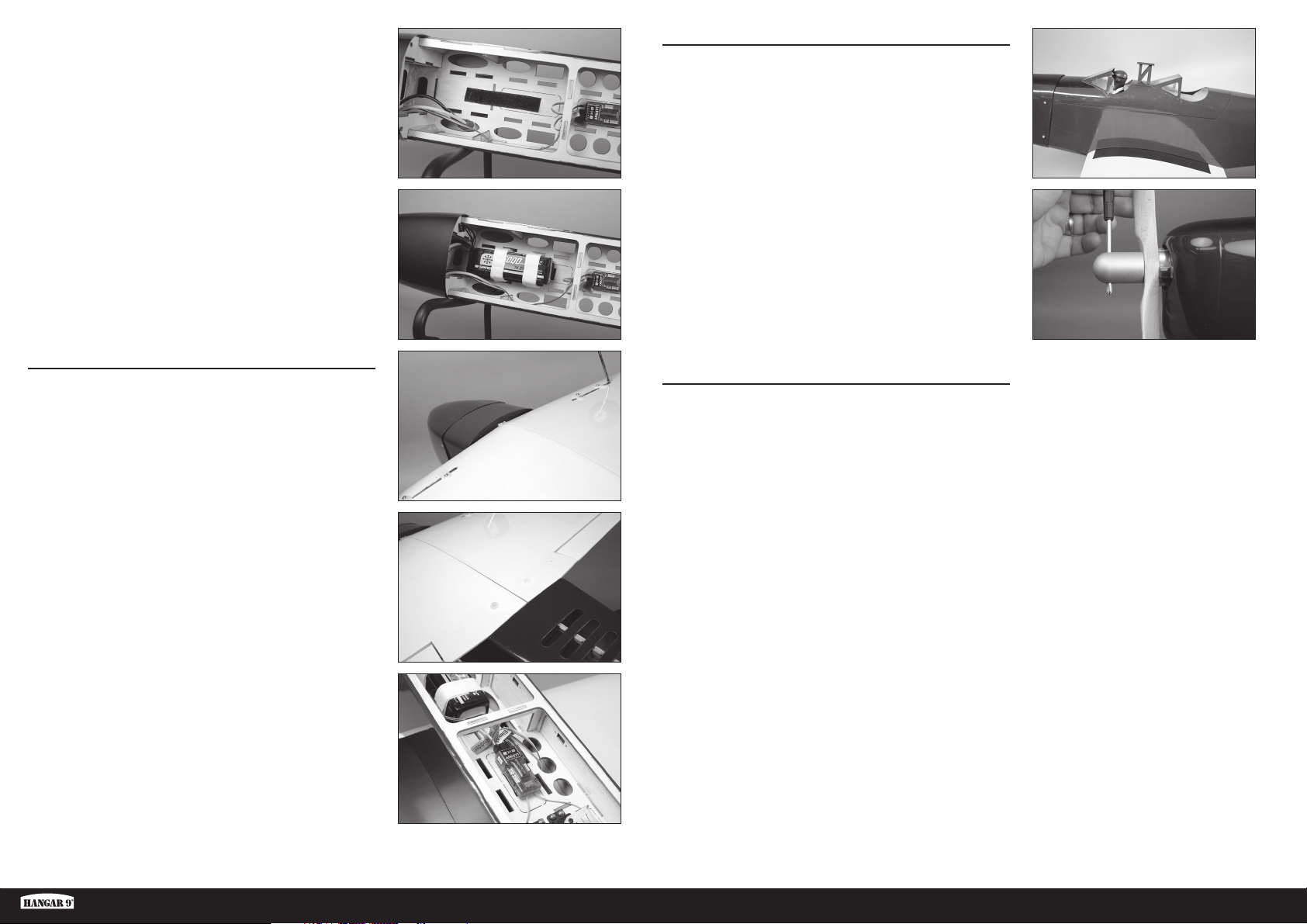
36. Eine Seite des Klettbands an der Akkuhalterung befestigen.
Optional: Eine dünne Schicht CA-Klebstoff mithilfe eines
Papiertuchs auf die Halterung auftragen. Den CA-Klebstoff
aushärten lassen, ehe das Klettband angebracht wird.
Wir empfehlen, die Klettbandseite mit den
Widerhaken auf dem Flugzeug, die Seite mit
den Schlaufen auf dem Akku anzubringen.
ABSCHLIESSENDE MONTAGE
41. Die Batterieabdeckung auf dem Rumpf montieren.
37. Die Schlaufenseite des Klettbands am Akku befestigen.
Sicherstellen, dass die Warnhinweise auf dem Akku nicht
überdeckt werden. Den Akku in den Rumpf einlegen und mit
dem Klettband im Rumpf sichern.
Die Platzierung des Akkus kann geändert werden,
um den Schwerpunkt anzupassen. Nach erfolgter
Anpassung die Akkuposition markieren, damit er nach
dem Laden wieder korrekt positioniert werden kann.
MONTAGE DER TRAGFLÄCHE
38. Die Tragfl äche auf den Rumpf schieben, dabei die Lasche
auf der Tragfl äche mit dem Schlitz im Rumpf ausrichten. Die
Lasche passt in den Rumpf, wobei die Vorderkante eng am
Rumpf anliegt.
39. Die Tragfl äche mit zwei Nylon-Flügelschrauben am Rumpf
befestigen. Die Schrauben mit einem Flachschraubendreher
festziehen.
42. Den Propeller auf die Motorwelle schieben. Schrauben Sie
die Spinnermutter auf die Motorwelle. Benutzen Sie einen
Sechskantschraubenschlüssel, der durch das Loch in der
Spinnermutter geführt wird, um die Mutter auf der Welle zu
befestigen.
Seien Sie um den Propeller herum sehr vorsichtig,
nachdem er installiert wurde. Um Verletzungen
vorzubeugen, behandeln Sie den Motor als ‚lebendig‘, d.h.
als ob er jederzeit ohne Vorwarnung starten könnte.
ANBRINGEN DER DECALS
43. Die Decals auf dem Modell anhand der Fotos der
Verpackungsgestaltung als Orientierung aufbringen. Mit
einer Sprühfl asche und einem Tropfen Geschirrspüler oder
Glasreiniger auf die Position der Decals sprühen, um eine
Neupositionierung des Decals zu ermöglichen. Ein Papiertuch
als Abzieher verwenden und überfl üssige Flüssigkeit unter
dem Decal entfernen. Das Modell über Nacht ruhen lassen,
sodass die verbleibende Flüssigkeit verdunsten kann.
40. Die Leitungen des Querruder-Servos mit dem Empfänger
verbinden.
Fun Scale PT-19 PNP
19 DE
Page 20
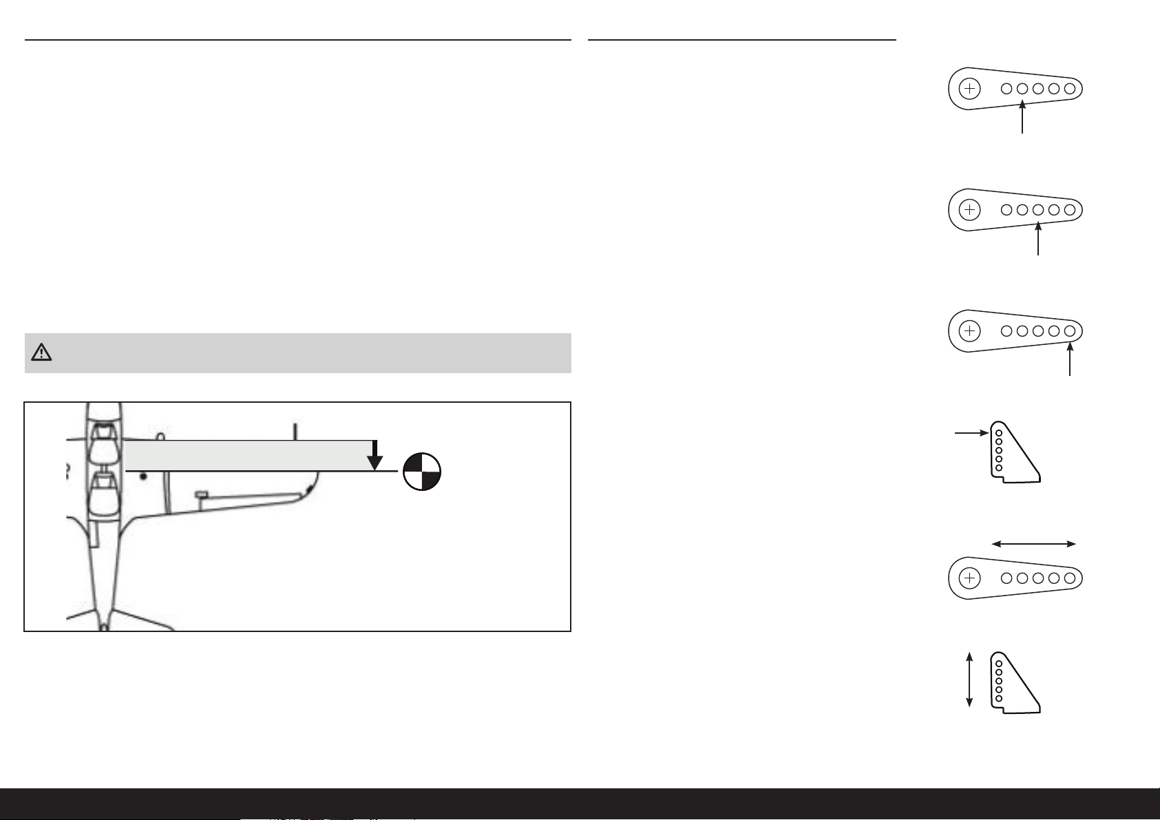
DER SCHWERPUNKT
Ein wichtiger Teil bei der Vorbereitung des Flugzeugs für den Flug ist das ordnungsgemäße Ausbalancieren des
Modells.
1. Die Tragfl ächen am Rumpf anbringen. Sicherstellen, dass die Leitungen vom Querruder an den entsprechenden
Leitungen vom Empfänger angeschlossen sind. Sicherstellen, dass die Leitungen nicht außerhalb des Rumpfs
liegen, ehe die Flügelschrauben festgezogen werden. Das Modell sollte vor dem Ausbalancieren fl ugbereit sein.
GESTÄNGEANSCHLÜSSE
Vor Überprüfung des Ruderausschlags sicherstellen, dass die
Gestänge wie abgebildet an den Servoarmen angeschlossen sind,
um einen korrekten Ruderausschlag zu erreichen.
Höhenruder
2. Der empfohlene Schwerpunkt (CG) für das Modell liegt 85 mm hinter der Vorderkante des Flügels.
3. Beim Ausbalancieren des Modells sicherstellen, dass es zusammengebaut und fl ugbereit ist. Das Flugzeug
mit den Fingern oder einem käufl ich erhältlichen Ständer umgekehrt an den auf der Tragfl äche angebrachten
Markierungen abstützen.
Der empfohlene Schwerpunkt (CG) ist der empfohlene Gleichgewichtspunkt für die ersten Flüge. Dieser bietet eine
sichere und stabile Einstellung zum bequemen Erkunden von Leistung und Handhabung des Modells.
Der CG-Bereich von 80mm bis 95mm stellt das Extrem des Gleichgewichts dar, mit dem das Modell im Flug getestet
wurde und sich als fl ugfähig erwies. Die Stabilität und Leistung des Modells variiert bei der Einstellung innerhalb dieses
Bereichs. Da der Flugstil und die Vorlieben eines jeden Piloten unterschiedlich sind, empfehlen wir, kleine Änderungen
am CG vorzunehmen, bis sich das bevorzugte Fluggefühl einstellt.
ACHTUNG: Vor einem Flug muss der Schwerpunkt des Flugzeug ausgerichtet
und das Flugzeug ordnungsgemäß ausbalanciert sein.
85mm
back from leading
edge at the root
Der Gabelkopf muss im äußeren Loch des Steuerhorns für
Seitenruder, Höhenruder und Querruder angebracht werden, um
einen korrekten Ruderausschlag zu erreichen.
Dies sind die empfohlenen Anschlüsse für die Gestängepositionen
bei ersten Flügen. Die Gestängepositionen können geändert
werden, um den Ruderausschlag zu erhöhen oder zu verringern,
sobald Sie mit den Flugeigenschaften Ihres Modells vertraut sind.
Querruder
Seitenruder
Steuerhörner
VerringernErhöhen
Erhöhen
Verringern
20DE
Page 21
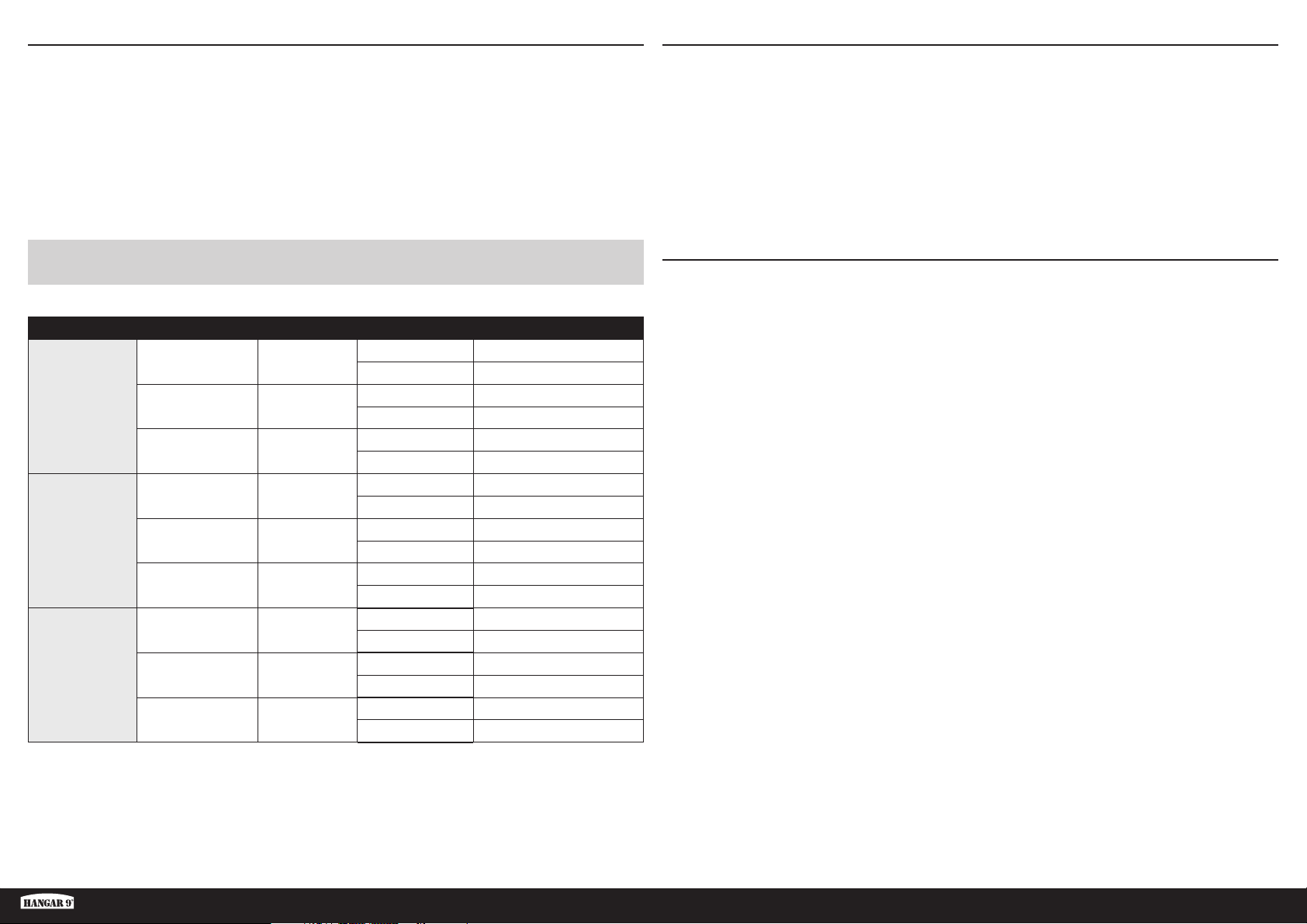
RUDERAUSSCHLAG
1. Den Sender und Empfänger des Modells einschalten. Die Bewegung des Seitenruders mit dem Empfänger prüfen.
Wird der Hebel nach rechts bewegt, sollte sich auch das Seitenruder nach rechts bewegen. Die Richtung auf dem
Servo am Empfänger bei Bedarf umkehren.
2. Die Bewegung des Höhenruders mit dem Funksystem prüfen. Wird der Hebel des Höhenruders auf dem Sender
nach unten bewegt, so bewegt sich das Höhenruder des Flugzeugs nach oben.
3. Die Bewegung des Querruders mit dem Funksystem prüfen. Wird der Hebel des Querruders nach rechts bewegt,
so bewegt sich das rechte Querruder nach oben und das linke Querruder nach unten.
4. Mit einem Lineal den Ausschlag von Höhen-, Quer- und Seitenruder einstellen.
VORFLUGKONTROLLE
• Akkus für Sender, Empfänger und Motor aufl aden. Die dem Ladegerät beigelegten Anweisungen befolgen. Die
Anweisungen des Herstellers der elektrischen Bauteile befolgen.
• Überprüfen Sie die Montage des Funkgeräts und stellen Sie sicher, dass sich alle Steuerfl ächen (Querruder,
Höhenruder, Ruder und Klappen) korrekt bewegen (d.h. in die richtige Richtung und mit den empfohlenen
Ausschlägen).
• Überprüfen Sie alle Teile der Anlenkungen (Ruderhörner, Servohebel und Gabelköpfe) und stellen sicher dass diese
gut befestigt und in einwandfreiem Zustand sind.
• Lassen Sie den Motor laufen. Wiederholen Sie mit laufenden Motor den Reichweitencheck. Die Reichweite sollte
nicht signifi kant beeinfl ußt werden.
BITTE ERHÖHEN SIE DIE BEWEGUNGEN DER STEUERUNGEN NICHT ÜBER DIE VOR DEM ERSTEN FLUG ANGEGEBENEN!
Dieses Modell reagiert sehr gut auf Nick- und Rollbewegungen mit kleinen Bewegungen.
Oberfl äche Rate Exponential Richtung Ausschlag
Nach oben 13 mm
Nach unten 13 mm
Nach oben 9 mm
Nach unten 9 mm
Nach oben 7 mm
Nach unten 7 mm
Nach oben 15 mm
Nach unten 15 mm
Nach oben 10,5 mm
Nach unten 10,5 mm
Nach oben 8 mm
Nach unten 8 mm
Rechts 36 mm
Links 36 mm
Rechts 24 mm
Links 24 mm
Rechts 18 mm
Links 18 mm
Querruder
Höhenruder
Seitenruder
Hoch 10%
Mitte 5%
Niedrig 0%
Hoch 10%
Mitte 5%
Niedrig 0%
Hoch 10%
Mitte 5%
Niedrig 0%
TÄGLICHER FLUG CHECK
• Überprüfen Sie die Spannung des Senderakkus. Fliegen Sie nicht wenn die Spannung unterhalb der vom Hersteller
empfohlenen Spannung liegt, da dieses zu einem Absturz führen könnte.
• Überprüfen Sie alle montierten Teile (Verbindungen, Schrauben, Muttern und Bolzen vor jedem Flug. Stellen Sie
sicher, dass nichts blockiert und alle Teile vernünftig gesichert sind.
• Stellen Sie sicher, dass sich alle Ruder in die richtige Richtung bewegen.
• Führen Sie einen Reichweitentest vor jeder Flugsession durch.
• Alle Servoleitungen und Stecker der Schalterkabel sollten im Empfänger gesichert sein.
Fun Scale PT-19 PNP
21 DE
Page 22

GARANTIE UND SERVICE INFORMATIONEN
Warnung
Ein ferngesteuertes Modell ist kein Spielzeug. Es kann, wenn es falsch eingesetzt wird, zu erheblichen Verletzungen
bei Lebewesen und Beschädigungen an Sachgütern führen. Betreiben Sie Ihr RC-Modell nur auf freien Plätzen und
beachten Sie alle Hinweise der Bedienungsanleitung des Modells wie auch der Fernsteuerung.
Garantiezeitraum
Exklusive Garantie Horizon Hobby LLC (Horizon) garantiert, dass dasgekaufte Produkt frei von Material- und
Montagefehlern ist. Der Garantiezeitraum entspricht den gesetzlichen Bestimmung des Landes, in dem das Produkt
erworben wurde. In Deutschland beträgt der Garantiezeitraum 6 Monate und der Gewährleistungszeitraum 18 Monate
nach dem Garantiezeitraum.
Einschränkungen der Garantie
(a) Die Garantie wird nur dem Erstkäufer (Käufer) gewährt und kann nicht übertragen werden. Der Anspruch
des Käufers besteht in der Reparatur oder dem Tausch im Rahmen dieser Garantie. Die Garantie erstreckt sich
ausschließlich auf Produkte, die bei einem autorisierten Horizon Händler erworben wurden. Verkäufe an dritte werden
von dieser Garantie nicht gedeckt. Garantieansprüche werden nur angenommen, wenn ein gültiger Kaufnachweis
erbracht wird. Horizon behält sich das Recht vor, diese Garantiebestimmungen ohne Ankündigung zu ändern oder
modifi zieren und widerruft dann bestehende Garantiebestimmungen.
(b) Horizon übernimmt keine Garantie für die Verkaufbarkeit des Produktes, die Fähigkeiten und die Fitness des
Verbrauchers für einen bestimmten Einsatzzweck des Produktes. Der Käufer allein ist dafür verantwortlich, zu prüfen,
ob das Produkt seinen Fähigkeiten und dem vorgesehenen Einsatzzweck entspricht.
(c) Ansprüche des Käufers ¬ Es liegt ausschließlich im Ermessen von Horizon, ob das Produkt, bei dem ein Garantiefall
festgestellt wurde, repariert oder ausgetauscht wird. Dies sind die exklusiven Ansprüche des Käufers, wenn ein Defekt
festgestellt wird.
Horizon behält sich vor, alle eingesetzten Komponenten zu prüfen, die in den Garantiefall einbezogen werden können.
Die Entscheidung zur Reparatur oder zum Austausch liegt nur bei Horizon. Die Garantie schließt kosmetische Defekte
oder Defekte, hervorgerufen durch höhere Gewalt, falsche Behandlung des Produktes, falscher Einsatz des Produktes,
kommerziellen Einsatz oder Modifi kationen irgendwelcher Art aus. Die Garantie schließt Schäden, die durch falschen
Einbau, falsche Handhabung, Unfälle, Betrieb, Service oder Reparaturversuche, die nicht von Horizon ausgeführt
wurden aus.
Ausgeschlossen sind auch Fälle die bedingt durch (vii) eine Nutzung sind, die gegen geltendes Recht, Gesetze oder
Regularien verstoßen haben. Rücksendungen durch den Käufer direkt an Horizon oder eine seiner Landesvertretung
bedürfen der Schriftform.
Schadensbeschränkung
Horizon ist nicht für direkte oder indirekte Folgeschäden, Einkommensausfälle oder kommerzielle Verluste, die in
irgendeinem Zusammenhang mit dem Produkt stehen verantwortlich, unabhängig ab ein Anspruch im Zusammenhang
mit einem Vertrag, der Garantie oder der Gewährleistung erhoben werden. Horizon wird darüber hinaus keine
Ansprüche aus einem Garantiefall akzeptieren, die über den individuellen Wert des Produktes hinaus gehen. Horizon hat
keinen Einfl uss auf den Einbau, die Verwendung oder die Wartung des Produktes oder etwaiger Produktkombinationen,
die vom Käufer gewählt werden. Horizon übernimmt keine Garantie und akzeptiert keine Ansprüche für in der folge
auftretende Verletzungen oder Beschädigungen. Mit der Verwendung und dem Einbau des Produktes akzeptiert der
Käufer alle aufgeführten Garantiebestimmungen ohne Einschränkungen und Vorbehalte.
Wenn Sie als Käufer nicht bereit sind, diese Bestimmungen im Zusammenhang mit der Benutzung des Produktes zu
akzeptieren, werden Sie gebeten, dass Produkt in unbenutztem Zustand in der Originalverpackung vollständig bei dem
Verkäufer zurückzugeben.
Sicherheitshinweise
Dieses ist ein hochwertiges Hobby Produkt und kein Spielzeug. Es muss mit Vorsicht und Umsicht eingesetzt werden
und erfordert einige mechanische wie auch mentale Fähigkeiten. Ein Versagen, das Produkt sicher und umsichtig
zu betreiben kann zu Verletzungen von Lebewesen und Sachbeschädigungen erheblichen Ausmaßes führen. Dieses
Produkt ist nicht für den Gebrauch durch Kinder ohne die Aufsicht eines Erziehungsberechtigten vorgesehen. Die
Anleitung enthält Sicherheitshinweise und Vorschriften sowie Hinweise für die Wartung und den Betrieb des Produktes.
Es ist unabdingbar, diese Hinweise vor der ersten Inbetriebnahme zu lesen und zu verstehen. Nur so kann der falsche
Umgang verhindert und Unfälle mit Verletzungen und Beschädigungen vermieden werden.
Fragen, Hilfe und Reparaturen
Ihr lokaler Fachhändler und die Verkaufstelle können eine Garantiebeurteilung ohne Rücksprache mit Horizon nicht
durchführen. Dies gilt auch für Garantiereparaturen. Deshalb kontaktieren Sie in einem solchen Fall den Händler, der
sich mit Horizon kurz schließen wird, um eine sachgerechte Entscheidung zu fällen, die Ihnen schnellst möglich hilft.
Wartung und Reparatur
Muss Ihr Produkt gewartet oder repariert werden, wenden Sie sich entweder an Ihren Fachhändler oder direkt an
Horizon.
Rücksendungen / Reparaturen werden nur mit einer von Horizon vergebenen RMA Nummer bearbeitet. Diese Nummer
erhalten Sie oder ihr Fachhändler vom technischen Service. Mehr Informationen dazu erhalten Sie im Serviceportal
unter www. Horizonhobby.de oder telefonisch bei dem technischen Service von Horizon.
Packen Sie das Produkt sorgfältig ein. Beachten Sie, dass der Originalkarton in der Regel nicht ausreicht, um
beim Versand nicht beschädigt zu werden. Verwenden Sie einen Paketdienstleister mit einer Tracking Funktion und
Versicherung, da Horizon bis zur Annahme keine Verantwortung für den Versand des Produktes übernimmt.
Bitte legen Sie dem Produkt einen Kaufbeleg bei, sowie eine ausführliche Fehlerbeschreibung und eine Liste aller
eingesendeten Einzelkomponenten. Weiterhin benötigen wir die vollständige Adresse, eine Telefonnummer für
Rückfragen, sowie eine Email Adresse.
Garantie und Reparaturen
Garantieanfragen werden nur bearbeitet, wenn ein Originalkaufbeleg von einem autorisierten Fachhändler beiliegt, aus
dem der Käufer und das Kaufdatum hervorgeht. Sollte sich ein Garantiefall bestätigen wird das Produkt repariert oder
ersetzt. Diese Entscheidung obliegt einzig Horizon Hobby.
Kostenpfl ichtige Reparaturen
Liegt eine kostenpfl ichtige Reparatur vor, erstellen wir einen Kostenvoranschlag, den wir Ihrem Händler übermitteln.
Die Reparatur wird erst vorgenommen, wenn wir die Freigabe des Händlers erhalten. Der Preis für die Reparatur ist
bei Ihrem Händler zu entrichten. Bei kostenpfl ichtigen Reparaturen werden mindestens 30 Minuten Werkstattzeit und
die Rückversandkosten in Rechnung gestellt. Sollten wir nach 90 Tagen keine Einverständniserklärung zur Reparatur
vorliegen haben, behalten wir uns vor, das Produkt zu vernichten oder anderweitig zu verwerten.
ACHTUNG: Kostenpfl ichtige Reparaturen nehmen wir nur für Elektronik und Motoren vor. Mechanische
Reparaturen, besonders bei Hubschraubern und RC-Cars sind extrem aufwendig und müssen deshalb vom
Käufer selbst vorgenommen werden.
10/15
22DE
Page 23
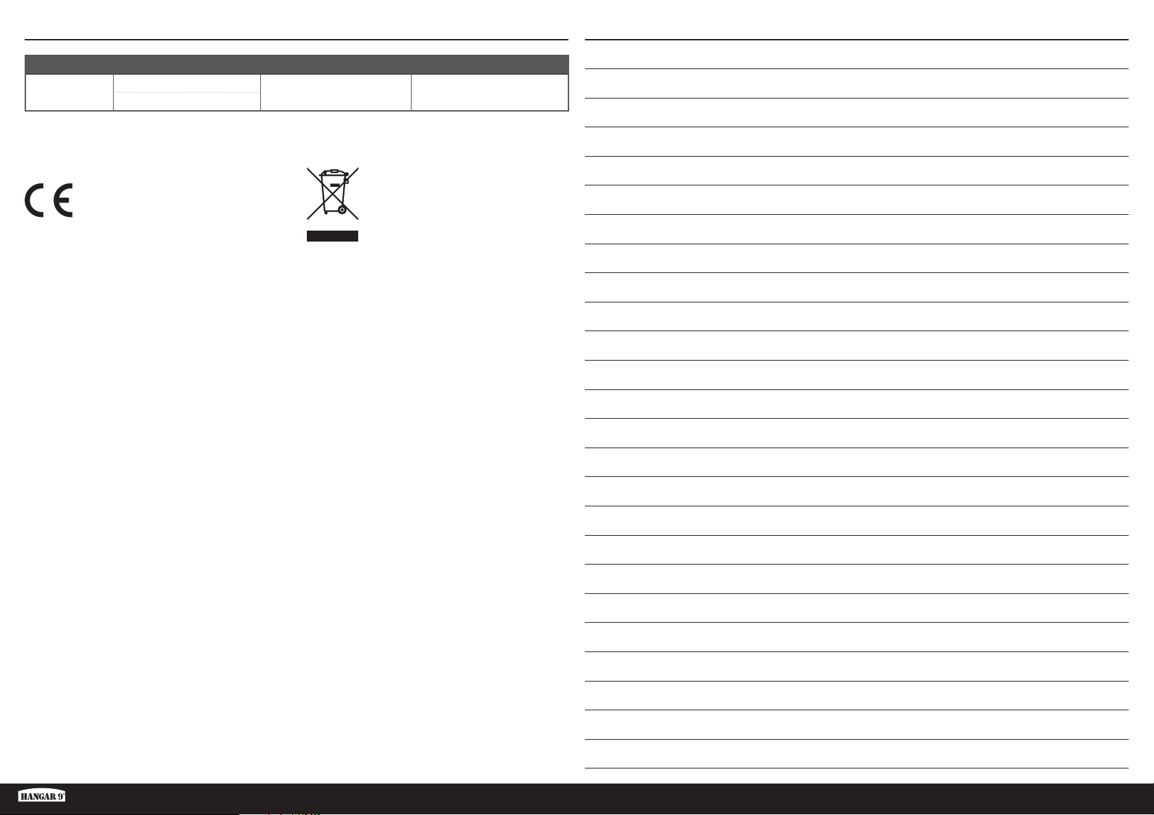
GARANTIE UND SERVICE KONTAKTINFORMATIONEN
Land des Kauf Horizon Hobby Telefon/Email Adresse Adresse
EU
Horizon Technischer Service
Horizon Hobby GmbH
+49 (0) 4121 2655 100
[email protected]
Hanskampring 9
D 22885 Barsbüttel, Germany
NOTIZEN ZUM AUFBAU UND FLIEGEN
EU Konformitätserklärung
Hiermit erklärt Horizon Hobby, LLC, dass das
Gerät den folgenden Richtlinien entspricht:
Öko-Design-Richtlinie 1275/2008;
RoHS 2-Richtlinie 2011/65 / EU;
RoHS 3-Richtlinie - Änderung 2011/65 / EU-Anhang II
2015/863;
Der vollständige Text der EU-Konformitätserklärung ist
unter folgender Internetadresse abrufbar: https://www.
horizonhobby.com/content/support-render-compliance.
Offi zieller EU-Hersteller:
Horizon Hobby, LLC
2904 Research Road
Champaign, IL 61822 USA
Offi zieller EU-Importeur:
Horizon Hobby, GmbH
Hanskampring 9
22885 Barsbüttel Germany
WEEE-HINWEIS:
Dieses Gerät ist gemäß der Europäischen
Richtlinie 2012/19/EU über Elektround Elektronik-Altgeräte (WEEE)
gekennzeichnet. Dieses Symbol weist
darauf hin, dass dieses Produkt kein
normaler Haushaltsabfall ist, sondern in einer
entsprechenden Sammelstelle für Elektro- und
Elektronik-Altgeräte entsorgt werden muss.
Fun Scale PT-19 PNP
23 DE
Page 24

REMARQUE
Les instructions, garanties et autres documents associés sont soumis à des modifi cations à la seule discrétion
d’HorizonHobby,LLC. Pour obtenir les documents à jour du produit, consultez le site horizonhobby.com ou www.
towerhobbies.com et cliquez sur l’onglet d’aide ou de ressources pour ce produit.
SIGNIFICATION DE CERTAINS TERMES SPÉCIFIQUES
Les termes suivants sont utilisés dans l’ensemble du manuel pour indiquer différents niveaux de danger lors de
l’utilisation de ce produit:
AVERTISSEMENT: Procédures qui, si elles ne sont pas suivies correctement, peuvent entraîner des dégâts matériels
et des blessures graves OU engendrer une probabilité élevée de blessure superfi cielle.
ATTENTION: Procédures qui, si elles ne sont pas suivies correctement, peuvent entraîner des dégâts matériels ET des
blessures graves.
REMARQUE: Procédures qui, si elles ne sont pas suivies correctement, peuvent entraîner des dégâts matériels ET
éventuellement un faible risque de blessures.
AVERTISSEMENT: Lisez la TOTALITÉ du manuel d’utilisation afi n de vous familiariser avec les caractéristiques du
produit avant de le faire fonctionner. Une utilisation incorrecte du produit peut entraîner sa détérioration, ainsi que des
risques de dégâts matériels, voire de blessures graves.
Les batteries
Suivez toujours les instructions du fabricant de vos batteries. Une mauvaise manipulation d’une batterie Li-Po peut
entraîner un incendie causant de graves dégâts matériels et des blessures corporelles.
Petites pièces
Ce kit contient des petites pièces qui ne doivent pas être laissées à la portée des enfants, ces pièces sont dangereuses
pour eux et peuvent entraîner de graves blessures.
CONSIGNES DE SÉCURITÉ CONCERNANT L’UTILISATION
• Inspectez votre modèle avant chaque vol.
• Surveillez les fréquences utilisées à proximité.
• Soyez toujours courtois et respectueux des autres utilisateurs de la zone de vol.
• Choisissez une zone dégagée de tout obstacle et suffi samment grande pour voler en toute sécurité.
• Contrôlez que la zone est libre de spectateurs avant de lancer votre modèle.
• Soyez conscient des autres activités aux alentours de votre vol, risque de confl it potentiel.
• Planifi ez votre vol avant de le commencer.
Ceci est un produit de loisirs sophistiqué. Il doit être manipulé avec prudence et bon sens et requiert des aptitudes
de base en mécanique. Toute utilisation irresponsable de ce produit ne respectant pas les principes de sécurité peut
provoquer des blessures, entraîner des dégâts matériels et endommager le produit. Ce produit n’est pas destiné à
être utilisé par des enfants sans la surveillance directe d’un adulte. N’essayez pas de modifi er ou d’utiliser ce produit
avec des composants incompatibles hors des instructions fournies par Horizon Hobby, LLC. Ce manuel comporte des
instructions relatives à la sécurité, au fonctionnement et à l’entretien. Il est capital de lire et de respecter la totalité
des instructions et avertissements du manuel avant l’assemblage, le réglage et l’utilisation, ceci afi n de manipuler
correctement l’appareil et d’éviter tout dégât matériel ou toute blessure grave.
14 ans et plus. Ceci n’est pas un jouet.
AVERTISSEMENTS RELATIFS À LA SÉCURITÉ
Lisez et suivez toutes les instructions relatives à la sécurité avant utilisation. Une utilisation inappropriée peut entraîner
un incendie, de graves blessures et des dégâts matériels.
Composants
Utilisez uniquement des composants compatibles. Si vous avez des questions concernant la compatibilité, référez-vous
à ce manuel ou contactez le service technique Horizon Hobby.
Le vol
Volez uniquement dans des zones dégagées pour un maximum de sécurité. Il est recommandé d’utiliser les pistes des
clubs d’aéromodélisme. Consultez votre mairie pour connaître les sites autorisés.
L’hélice
Gardez toujours les éléments non fi xés pouvant s’emmêler à l’écart de l’hélice. Cela inclut les vêtements amples et
d’autres objets comme des crayons et des tournevis. Gardez vos mains éloignées de l’hélice, car il y a un risque de
blessure.
AVANT DE COMMENCER L’ASSEMBLAGE
• Retirez toutes les pièces des sachets pour les inspecter.
• Inspectez soigneusement le fuselage, les ailes et les empennages.
• Si un élément est endommagé, contactez votre revendeur.
• ll est recommandé de préparer tous les éléments du système de la radio.
• Cela inclut la charge des batteries comme la mise au neutre des trims et des manches de votre émetteur.
• Si vous utilisez une radio programmable, sélectionnez une mémoire libre afi n d’y enregistrer les paramètres de ce
modèle.
• Nous vous recommandons d’affecter maintenant le récepteur à l’émetteur en suivant les instructions fournies avec
votre radio.
REMARQUE: Reconnectez le système radio une fois que tous les coudes de contrôle sont confi gurés. Cette action
empêche les servos de se déplacer vers leurs extrémités jusqu’à la connexion de l’émetteur et du récepteur. Cela
garantit aussi que les paramètres d’inversion du servo sont enregistrés dans le système radio.
24FR
Page 25
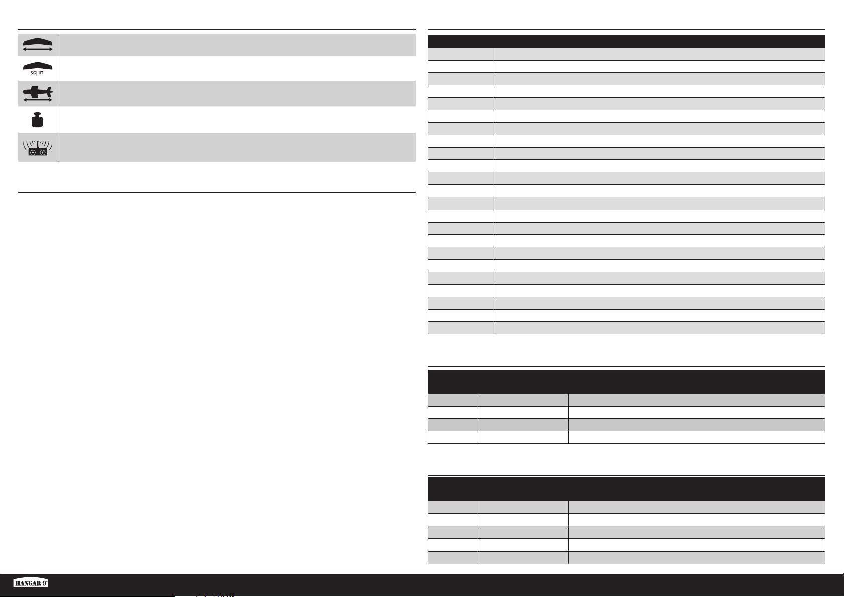
PIÈCES DE RECHANGESPÉCIFICATIONS
561/2 in (1435 mm)
537 sq in (35.65 dm2)
46.18 in (1172 mm)
1569 g (55 oz) sans batterie, 2079 g (73 oz) avec la batterie recommandée
5canaux (ou plus)
TABLE DES MATIÈRES
Avertissements relatifs à la sécurité ............................................................................................................................24
Consignes de sécurité concernant l’utilisation .............................................................................................................24
Avant de commencer l’assemblage ............................................................................................................................24
Spécifi cations .............................................................................................................................................................25
Pièces de rechange ....................................................................................................................................................25
Nécessaire pour terminer l’appareil ............................................................................................................................25
Pièces en option .........................................................................................................................................................25
Batteries en option pour haute puissance (pour l’hélice 12x6) ................................................................................... 26
Outils et adhésifs nécessaires .....................................................................................................................................26
Outils et adhésifs en option .........................................................................................................................................26
Précautions de montage .............................................................................................................................................26
Retrait des faux-plis .................................................................................................................................................... 26
Vérifi cation des servos d’aileron ..................................................................................................................................26
Installation du train d’atterrissage ............................................................................................................................... 27
Assemblage des panneaux d’aile ................................................................................................................................27
Installation du stabilisateur et de la dérive ..................................................................................................................27
Installation du récepteur .............................................................................................................................................29
Connexion des servos de la gouverne de direction et de la profondeur ........................................................................29
Montage du capot et de la batterie..............................................................................................................................29
Installation de l’aile .....................................................................................................................................................30
Assemblage fi nal ........................................................................................................................................................30
Application des autocollants .......................................................................................................................................30
Centre De Gravité .......................................................................................................................................................31
Connexions des barres de liaison ................................................................................................................................31
Débattements .............................................................................................................................................................32
Checklist d’avant vol ...................................................................................................................................................32
Contrôles systématiques .............................................................................................................................................32
Garantie et réparations ...............................................................................................................................................33
Coordonnées de Garantie et réparations .....................................................................................................................34
Informations de IC.......................................................................................................................................................34
Informations de conformité pour l’Union européenne ..................................................................................................34
Référence Description
HAN318001 Fuselage
HAN318002 Panneaux d’aile
HAN318003 Train d’atterrissage
HAN318004 Stabilisateur
HAN318005 Stabilisateur vertical
HAN318006 Assemblage de roulette de queue
HAN318007 Cache d’écrou de queue
HAN318009 Figurine de pilote
HAN318010 Trappe avec pilote
HAN318011 Verrière
HAN318012 Boîtier du moteur
HAN318013 Roues
HAN318014 Jeu de tringleries
HAN318015 Vis papillon
HAN318016 Sachet de visserie
HAN318017 Matériel en plastique
HAN318018 Planche de décoration
HAN318019 Caches du train d’atterrissage
HAN318020 Hélice, 14x8,5
HAN338008 Clé d’aile
SPMSA391 Servo standard
SPMXAE1060C Variateur ESC 60A Smart Avian 6S
SPMXAM2100 Moteur 14pôles 4250-600kV
NÉCESSAIRE POUR TERMINER L’APPAREIL
Nombre
requis
2 SPMA3050 Rallonge de servo standard de 76,2mm (3po)
1 SPMAR637T Récepteur de télémétrie 6canaux SAFE et AS3X AR637T
1 SPMR6775 Émetteur uniquement 6canaux NX6
1 SPMX50004S30 Li-Po 5000mAh 4S 14,8V Smart 30C IC5
Référence Description
PIÈCES EN OPTION
Nombre
requis
1 APC12060E Hélice électrique, 12 x 6E
1 APC14085E Hélice électrique, 14 x 8,5E
1 SPMAR8360T Récepteur avec télémétrie 8canaux SAFE AR8360T
1
1 SPMR8200 Émetteur uniquement DSMX 8canaux NX8
Référence Description
SPMR10100 Émetteur uniquement 10canaux NX10
Fun Scale PT-19 PNP
25 FR
Page 26
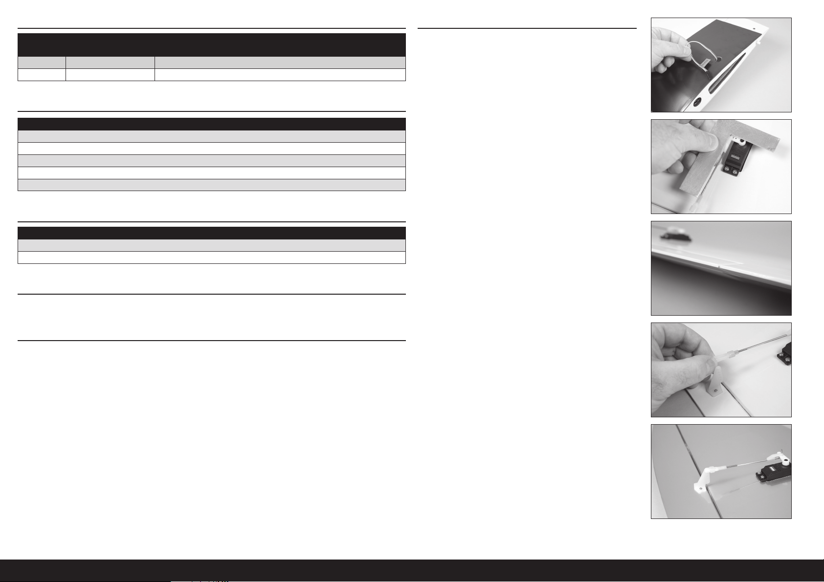
BATTERIES EN OPTION POUR HAUTE PUISSANCE (POUR L’HÉLICE 12X6)
VÉRIFICATION DES SERVOS D’AILERON
Nombre
requis
1 SPMX40006S30 4000mAh 6S 22.2V Smart 30C; IC5
1 SPMX50006S50 5000mAh 6S 22.2V Smart 50C; IC5
Référence Description
OUTILS ET ADHÉSIFS NÉCESSAIRES
Description
Support d’équilibrage
Tournevis plat, petit et grand
Clés à douilles : 1/4 pouce
Tournevis cruciforme: #1, #2
Équerre
OUTILS ET ADHÉSIFS EN OPTION
Description
Colle silicone
Colle cyano fi ne
PRÉCAUTIONS DE MONTAGE
Pendant le montage, nous recommandons de poser les pièces sur une surface douce comme une serviette douce pour
éviter de cabosser les plaques.
RETRAIT DES FAUX-PLIS
Des faux-plis peuvent se former sur l’entoilage de votre modèle lors du transport. Ils nécessitent l’utilisation d’un
pistolet thermique (HAN100) et de gants d’entoilage (HAN150) ou de fer d’entoilage (HAN101) avec une douille en
fer scellante (HAN141) pour les retirer. Faites attention lorsque vous travaillez autour des zones où les couleurs se
chevauchent afi n d’éviter de séparer les couleurs. Évitez d’appliquer trop de chaleur, cela pourrait séparer les couleurs.
Placer un chiffon humide frais sur les couleurs adjacentes permet également d’éviter la séparation des couleurs lors du
retrait des faux-plis.
1. Faites passer les fi ls du servo d’aileron par les trous en haut
de l’aile.
2. Raccordez le servo d’aileron au récepteur. Centrez le manche
de l’aileron et le trim. Vérifi ez que la barre de liaison est à 90°
par rapport au bras de servo. SI ce n’est pas le cas, retirez
le bras de servo et ajustez-le ou utilisez le trim secondaire
lorsque vous utilisez une radio ordinateur.
3. Vérifi ez l’aileron pour vous assure qu’il est aligné avec l’aile.
4. Si l’aileron n’est pas aligné, déconnectez la manille et vissez-
la ou dévissez-la pour corriger l’alignement de l’aileron.
5. Une fois réglée, reconnectez la manille au renvoi de
commande de l’aileron. Faites glisser la bague de retenue en
silicone sur les fourches de la manille pour la fi xer au renvoi
de commande.
Répétez la procédure pour l’autre panneau d’aile.
26FR
Page 27
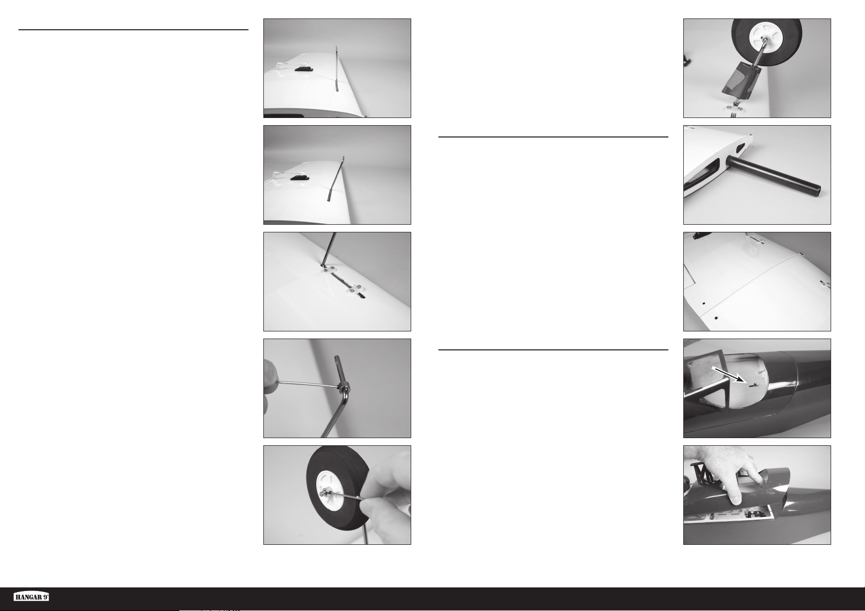
INSTALLATION DU TRAIN D’ATTERRISSAGE
6. Placez le fi l du train d’atterrissage dans l’aile. Le train
d’atterrissage penche vers l’avant s’il est installé
correctement. Le fi l doit être aligné avec le bas de l’aile
lorsqu’il est installé.
Facultatif
11. Utilisez une colle silicone fl exible pour fi xer les carénages
du train d’atterrissage sur le train d’atterrissage. Utilisez
du ruban adhésif à faible adhérence pour maintenir les
carénages jusqu’au séchage complet de la colle.
ASSEMBLAGE DES PANNEAUX D’AILE
8. Fixez le train d’atterrissage à l’aide les 2 sangles du train
d’atterrissage en nylon et des 4 vis autotaraudeuses 3mm x
12. Faussez les vis dans les trou pré-percés, puis utilisez un
tournevis cruciforme Phillips n°2 pour serrer les vis.
9. Insérez une bague sur le train d’atterrissage. Faussez une
vis de fi xation M3 x 4mm dans la bague. Utilisez la clé à six
pans fournie pour serrer la vis de fi xation sur la zone plate du
train d’atterrissage le plus proche du pied vertical.
12. Glissez le tube d’aile dans la cavité de l’aile. Il doit glisser
facilement, ne forcez pas au-delà de ce qui est nécessaire.
13. Faites glisser l’autre panneau d’aile sur le tube d’aile. Les
panneaux d’aile sont bien ajustés l’un contre l’autre, sans
espace.
INSTALLATION DU STABILISATEUR ET DE LA DÉRIVE
14. Retirez la trappe de la verrière du fuselage en faisant glisser
le loquet situé à l’avant du cockpit arrière.
10. Faites glisser la roue sur le train d’atterrissage, puis fi xez-la à
l’aide d’une bague et de la vis de fi xation M3 x 4mm.
Facultatif: Utilisez une petite quantité de frein-filet sur
chaque vis de fixation pour les empêcher de se desserrer.
Fun Scale PT-19 PNP
15. Levez la trappe à l’arrière et retirez-la du fuselage. Mettez-la
de côté dans un endroit sûr.
27 FR
Page 28
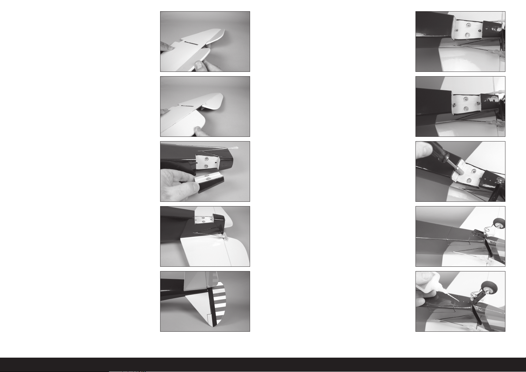
16. Pliez plusieurs fois la profondeur dans une amplitude de
mouvements pour rompre les charnières.
21. Faites glisser un écrou no4 sur chacune des tiges fi letées.
22. Vissez les écrous4-40 sur les tiges fi letées.
18. Retirez la trappe de fuselage inférieure sécurisée
magnétiquement du fuselage. Mettez-la de côté dans un
endroit sûr.
19. Glissez le stabilisateur dans la fente du fuselage. Assurez-
vous que le renvoi de commande est orienté vers le bas du
fuselage. Assurez-vous que le stabilisateur est placé vers
l’avant et que la fente du stabilisateur est alignée avec la
fente du fuselage de la dérive.
20. Rompez les charnières de gouverne de direction à l’aide de
la même méthode que les charnières de profondeur. Glissez
la dérive en place. Le support de roue de queue devra être
manipulé pendant l’installation de la dérive.
23. Utilisez un tournevis à écrou11mm (1/4po) pour serrer les
écrous. Veillez à ne pas serrer excessivement les écrous qui
pourraient endommager le fuselage ou la dérive.
24. Remettez la trappe de fuselage inférieure en position sur le
fuselage.
Facultatif
25. Déposez quelques gouttes de CA fi ne dans chacun des trois
trous pour les vis de support de la roue de queue. Avant de
continuer, laissez la colle sécher complètement.
28FR
Page 29
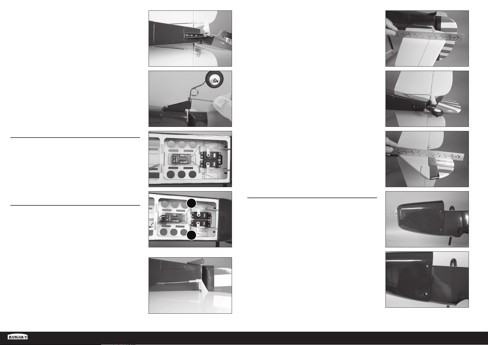
26. Utilisez les trois vis à tôle no2x5/16po pour fi xer le support
de la roue de queue au fuselage. Utilisez un tournevis
cruciforme n
o
1 pour serrer les vis.
31. Utilisez un bord rectiligne ou une règle pour vérifi er
l’alignement de la profondeur avec le stabilisateur. La règle
reposera à plat sur les deux une fois correctement alignée.
Ajustez la manille sur la barre de liaison de façon à aligner la
profondeur. Assurez-vous de glisser la bague de retenue en
silicone sur les fourches de la manille pour éviter qu’elle ne
se desserre en vol.
27. Insérez la bague de la roue contre le support de la roue de
queue. Assurez-vous qu’il y a suffi samment de place pour
que la gouverne puisse bouger librement. Serrez la vis
de fi xation dans la bague à l’aide d’une clé à six pans de
1,5mm.
INSTALLATION DU RÉCEPTEUR
28. Installez le récepteur dans le fuselage à l’aide du ruban
adhésif double-face. Consultez les instructions du récepteur
pour obtenir plus d’informations sur le montage du récepteur
et l’installation de l’antenne.
Utilisez du ruban adhésif transparent pour
fixer l’antenne, de manière à ne pas interférer
avec le fonctionnement des servos.
CONNEXION DES SERVOS DE LA GOUVERNE DE
DIRECTION ET DE LA PROFONDEUR
29. Raccordez les servos de la gouverne de direction(1) et de la
profondeur(2) au récepteur. Centrez les manches et les trims
de la gouverne de direction et de la profondeur. Vérifi ez que
la barre de liaison est à 90° par rapport au bras de servo.
SI ce n’est pas le cas, retirez le bras de servo et ajustez-le
ou utilisez le trim secondaire lorsque vous utilisez une radio
ordinateur.
30. Connectez la manille sur le trou extérieur du renvoi de
commande de l’élévateur.
32. Fixez la manille sur l’orifi ce extérieur du renvoi de commande
de la profondeur.
33. Utilisez un bord rectiligne ou une règle pour vérifi er
l’alignement entre le gouvernail et la dérive. La règle reposera
à plat sur les deux une fois correctement alignée. Ajustez la
manille sur la barre de liaison de façon à aligner la gouverne.
Assurez-vous de glisser la bague de retenue en silicone sur
les fourches de la manille pour éviter qu’elle ne se desserre
en vol.
MONTAGE DU CAPOT ET DE LA BATTERIE
1
2
34. Glissez le capot sur le fuselage.
35. Fixez le capot à l’aide des 4 vis autotaraudeuses 3mm x
12mm et d’un tournevis cruciforme Phillips n°2. Deux vis
sont utilisées de chaque côté du capot.
Fun Scale PT-19 PNP
29 FR
Page 30
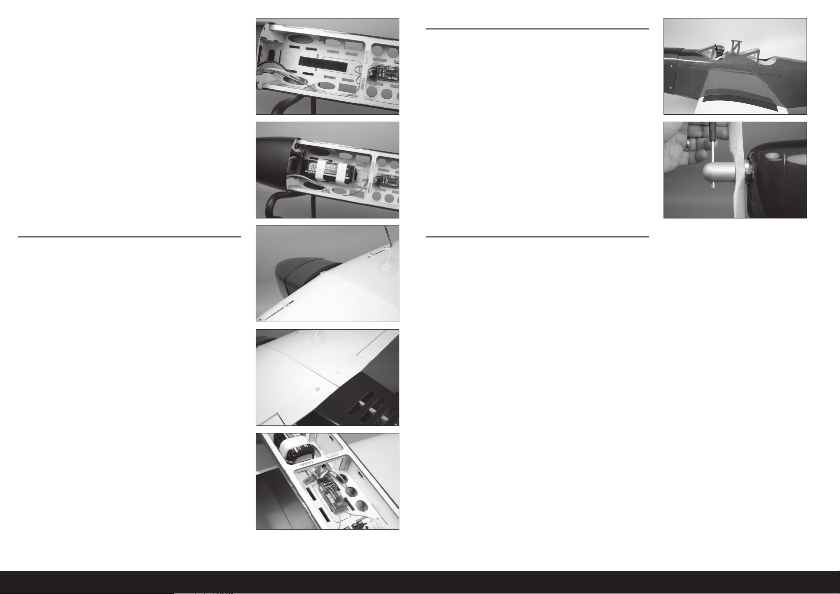
36. Appliquez un côté de la bande scratch sur la tablette de la
batterie.
Facultatif: Appliquez une fine couche de CA fine
sur la tablette à l’aide de papier absorbant. Laissez
sécher la CA avant d’appliquer la bande scratch.
Nous vous recommandons d’appliquer la partie
crochets de la bande scratch sur la cellule
et la partie boucles sur la batterie.
37. Appliquez la partie appariée de la bande scratch sur la
batterie. Assurez-vous de ne pas recouvrir des étiquettes de
sécurité sur la batterie. Fixez la batterie au fuselage à l’aide
de la bande scratch fournie.
ASSEMBLAGE FINAL
41. Installez la trappe de la verrière sur le fuselage.
42. Faites glisser l’hélice sur l’arbre du moteur. Vissez l’écrou du
cône sur l’arbre du moteur. Utilisez une clé à six pans passée
à travers le trou de l’écrou du cône pour serrer l’écrou sur
l’arbre.
La position de la batterie peut être modifiée pour
ajuster le centre de gravité. Une fois ajusté, indiquez
l’emplacement de la batterie afin de pouvoir la replacer
dans la bonne position, après l’avoir chargée.
INSTALLATION DE L’AILE
38. Glissez l’aile sur le fuselage, en alignant la languette de
l’aile avec la fente du fuselage. La languette s’insère dans le
fuselage, avec le bord d’attaque contre le fuselage.
39. Fixez l’aile au fuselage à l’aide des deux vis papillon en nylon.
Serrez les vis à l’aide d’un tournevis plat.
40. Raccordez les fi ls du servo d’aileron au récepteur.
Faites attention une fois que l’hélice a été installée. Pour
éviter toute blessure, partez du principe que le moteur est
actif et qu’il peut démarrer inopinément sans prévenir.
APPLICATION DES AUTOCOLLANTS
43. Appliquez les autocollants à votre modèle à l’aide des photos
fournies. Utilisez un vaporisateur et une goutte de liquide
vaisselle ou de nettoyant pour vitres que vous vaporiserez à
l’emplacement de l’autocollant pour le repositionner. Utilisez
du papier absorbant pour retirer l’excédent de liquide sous
l’autocollant. Laissez reposer le modèle toute une nuit pour
permettre l’évaporation du liquide résiduel.
30FR
Page 31
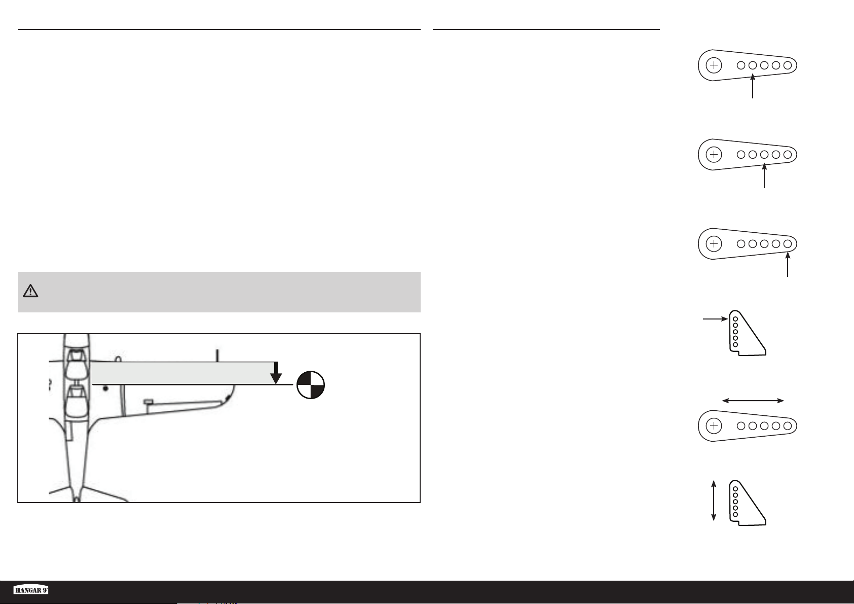
CENTRE DE GRAVITÉ
Une des étapes importantes de la préparation d’un modèle est son équilibrage.
1. Fixez les ailes au fuselage. Vérifi ez que les ailerons sont reliés aux prises appropriées du récepteur. Contrôlez
que les câbles ne dépassent pas du fuselage avant de serrer les ailes. Votre modèle doit être prêt à voler pour
effectuer l’équilibrage.
2. L’emplacement du centre de gravité recommandé de votre modèle se situe à 85 mm en arrière du bord d’attaque
de l’aile.
3. Lorsque vous équilibrez votre maquette, assurez-vous qu’elle est assemblée et qu’elle est prête pour le vol. Tenez
l’avion à l’envers au niveau des marquages réalisés sur l’aile ou avec un support d’équilibrage disponible dans le
commerce.
Le centre de gravité (CG) suggéré représente le point d’équilibre recommandé pour les premiers vols. Il assure un
réglage sûr et stable, afi n de pouvoir découvrir confortablement les performances de votre modèle et de le manipuler
aisément.
Les centres de gravité compris entre 80 et 95mm représentent les points extrêmes d’équilibre pour lesquels le modèle
a été testé en vol, et avec lesquels il pouvait voler. La stabilité et les performances du modèle varient avec un réglage
compris dans cette plage. Comme le style de pilotage et les préférences de chaque pilote sont différents, nous vous
recommandons d’ajuster légèrement le centre de gravité jusqu’à trouver votre préférence.
CONNEXIONS DES BARRES DE LIAISON
Avant de vérifi er les coudes de commande, assurez-vous que
les barres de liaison sont connectées aux bras de servo, comme
illustré, afi n de parvenir au coude de commande approprié.
Gouverne de profondeur
Ailerons
Gouverne de direction
ATTENTION: Le centre de gravité de votre modèle doit être parfaitement réglé avant de tenter un vol.
85mm
back from leading
edge at the root
La manille doit être fi xée à l’orifi ce extérieur du coude de
commande du gouvernail, de la profondeur et des ailerons, afi n de
parvenir au coude de commande approprié.
Voici les connexions recommandées pour les emplacements des
barres de liaison pour vos premiers vols. L’emplacement des
barres de liaison peut être modifi é pour augmenter ou réduire
l’inclinaison, une fois que vous serez habitué aux caractéristiques
de votre modèle.
Renvois de commande
AugmentationRéduction
Réduction
Augmentation
Fun Scale PT-19 PNP
31 FR
Page 32
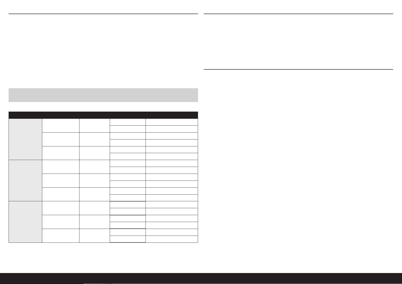
DÉBATTEMENTS
1. Mettez l’émetteur et le récepteur de votre maquette sous tension. Vérifi ez le mouvement de la dérive à l’aide
de l’émetteur. Lorsque le manche se déplace vers la droite, la dérive doit également se déplacer vers la droite.
Inversez le sens du servo au niveau de l’émetteur le cas échéant.
2. Vérifi ez le mouvement de profondeur à l’aide du système radio. Actionner le manche de profondeur vers le bas de
l’émetteur fait monter la profondeur de l’avion.
3. Vérifi ez le mouvement des ailerons à l’aide du système radio. Actionner le manche des ailerons vers la droite fait
monter l’aileron droit et descendre l’aileron gauche.
CHECKLIST D’AVANT VOL
• Chargez l’émetteur, le récepteur et les batteries du moteur. Suivez les instructions fournies avec le chargeur. Suivez
toutes les instructions du fabricant pour vos composants électroniques.
• Vérifi ez l’installation de la radio et assurez-vous que toutes les surfaces de commande (aileron, élévateur, gouverne,
et volets) bougent correctement (c’est-à-dire dans la bonne direction et avec les amplitudes recommandées).
• Contrôlez tous les accessoires (guignols, palonniers et chapes) pour être sûr qu’ils sont en bon état.
• Avant chaque session de vol (et surtout avec un nouveau modèle), effectuez un test de portée radio. Consultez le
manuel de votre radio pour les instructions pour effectuer un test de portée.
4. Utilisez un réglet pour ajuster les débattements de profondeur, des ailerons et de la dérive.
Ce sont des lignes directrices générales pour le vol sportif et acrobatique provenant de nos propres tests de vol. Vous
pouvez essayer des taux supérieurs ou inférieurs qui correspondent à votre style de vol préféré.
VEUILLEZ NE PAS AUGMENTER LES MOUVEMENTS DES COMMANDES PAR RAPPORT À CEUX ILLUSTRÉS AVANT LE
PREMIER VOL ! Ce modèle est très réactif au tangage et au roulis avec de petits mouvements.
Surface Débattement d’exponentiel Direction Coude
Haut 13 mm
Bas 13 mm
Haut 9 mm
Bas 9 mm
Haut 7 mm
Bas 7 mm
Haut 15 mm
Bas 15 mm
Haut 10,5 mm
Bas 10,5 mm
Haut 8 mm
Bas 8 mm
Vers la droite 36 mm
Vers la gauche 36 mm
Vers la droite 24 mm
Vers la gauche 24 mm
Vers la droite 18 mm
Vers la gauche 18 mm
Aileron
Profondeur
Dérive
Élevé 10%
Demi 5%
Bas 0%
Élevé 10%
Demi 5%
Bas 0%
Élevé 10%
Demi 5%
Bas 0%
CONTRÔLES SYSTÉMATIQUES
• Contrôlez la tension de la batterie de l’émetteur. Ne volez jamais en dessous de la tension minimale recommandée
par le fabricant. Le non-respect de cette consigne pourrait entraîner un crash.
• Contrôlez tous les accessoires (guignols, palonniers et chapes) pour être sûr qu’ils sont en bon état.
• Vérifi ez que toutes les gouvernes fonctionnent de manière correcte.
• Effectuez un test de portée avant chaque journée de vol.
• Tous les fi ls de servo et les prises du faisceau du commutateur devraient être fi xés dans le récepteur.
32FR
Page 33

GARANTIE ET RÉPARATIONS
Durée de la garantie
Garantie exclusive - Horizon Hobby, LLC (Horizon) garantit que le Produit acheté (le « Produit ») sera exempt de défauts
matériels et de fabrication à sa date d’achat par l’Acheteur. La durée de garantie correspond aux dispositions légales
du pays dans lequel le produit a été acquis. La durée de garantie est de 6 mois et la durée d’obligation de garantie de
18 mois à l’expiration de la période de garantie.
Limitations de la garantie
(a) La garantie est donnée à l’acheteur initial (« Acheteur ») et n’est pas transférable. Le recours de l’acheteur consiste
en la réparation ou en l’échange dans le cadre de cette garantie. La garantie s’applique uniquement aux produits
achetés chez un revendeur Horizon agréé. Les ventes faites à des tiers ne sont pas couvertes par cette garantie. Les
revendications en garantie seront acceptées sur fourniture d’une preuve d’achat valide uniquement. Horizon se réserve
le droit de modifi er les dispositions de la présente garantie sans avis préalable et révoque alors les dispositions de
garantie existantes.
(b) Horizon n’endosse aucune garantie quant à la vendabilité du produit ou aux capacités et à la forme physique de
l’utilisateur pour une utilisation donnée du produit. Il est de la seule responsabilité de l’acheteur de vérifi er si le produit
correspond à ses capacités et à l’utilisation prévue.
(c) Recours de l’acheteur – Il est de la seule discrétion d’Horizon de déterminer si un produit présentant un cas de
garantie sera réparé ou échangé. Ce sont là les recours exclusifs de l’acheteur lorsqu’un défaut est constaté.
Horizon se réserve la possibilité de vérifi er tous les éléments utilisés et susceptibles d’être intégrés dans le cas de
garantie. La décision de réparer ou de remplacer le produit est du seul ressort d’Horizon. La garantie exclut les défauts
esthétiques ou les défauts provoqués par des cas de force majeure, une manipulation incorrecte du produit, une
utilisation incorrecte ou commerciale de ce dernier ou encore des modifi cations de quelque nature qu’elles soient.
La garantie ne couvre pas les dégâts résultant d’un montage ou d’une manipulation erronés, d’accidents ou encore du
fonctionnement ainsi que des tentatives d’entretien ou de réparation non effectuées par Horizon. Les retours effectués
par le fait de l’acheteur directement à Horizon ou à l’une de ses représentations nationales requièrent une confi rmation
écrite.
Limitation des dommages
Horizon ne saurait être tenu pour responsable de dommages conséquents directs ou indirects, de pertes de revenus ou
de pertes commerciales, liés de quelque manière que ce soit au produit et ce, indépendamment du fait qu’un recours
puisse être formulé en relation avec un contrat, la garantie ou l’obligation de garantie. Par ailleurs, Horizon n’acceptera
pas de recours issus d’un cas de garantie lorsque ces recours dépassent la valeur unitaire du produit. Horizon n’exerce
aucune infl uence sur le montage, l’utilisation ou la maintenance du produit ou sur d’éventuelles combinaisons de
produits choisies par l’acheteur. Horizon ne prend en compte aucune garantie et n‘accepte aucun recours pour les
blessures ou les dommages pouvant en résulter. Horizon Hobby ne saurait être tenu responsable d’une utilisation ne
respectant pas les lois, les règles ou règlementations en vigueur.
En utilisant et en montant le produit, l’acheteur accepte sans restriction ni réserve toutes les dispositions relatives à la
garantie fi gurant dans le présent document. Si vous n’êtes pas prêt, en tant qu’acheteur, à accepter ces dispositions
en relation avec l’utilisation du produit, nous vous demandons de restituer au vendeur le produit complet, non utilisé et
dans son emballage d’origine.
Indications relatives à la sécurité
Ceci est un produit de loisirs perfectionné et non un jouet. Il doit être utilisé avec précaution et bon sens et nécessite
quelques aptitudes mécaniques ainsi que mentales. L’incapacité à utiliser le produit de manière sure et raisonnable
peut provoquer des blessures et des dégâts matériels conséquents. Ce produit n’est pas destiné à être utilisé par des
enfants sans la surveillance par un tuteur. La notice d’utilisation contient des indications relatives à la sécurité ainsi
que des indications concernant la maintenance et le fonctionnement du produit. Il est absolument indispensable de lire
et de comprendre ces indications avant la première mise en service. C’est uniquement ainsi qu’il sera possible d’éviter
une manipulation erronée et des accidents entraînant des blessures et des dégâts. Horizon Hobby ne saurait être tenu
responsable d’une utilisation ne respectant pas les lois, les règles ou règlementations en vigueur.
Questions, assistance et réparations
Votre revendeur spécialisé local et le point de vente ne peuvent effectuer une estimation d’éligibilité à l’application de
la garantie sans avoir consulté Horizon. Cela vaut également pour les réparations sous garantie. Vous voudrez bien,
dans un tel cas, contacter le revendeur qui conviendra avec Horizon d’une décision appropriée, destinée à vous aider le
plus rapidement possible.
Maintenance et réparation
Si votre produit doit faire l’objet d’une maintenance ou d’une réparation, adressez-vous soit à votre revendeur
spécialisé, soit directement à Horizon. Emballez le produit soigneusement. Veuillez noter que le carton d’emballage
d’origine ne suffi t pas, en règle générale, à protéger le produit des dégâts pouvant survenir pendant le transport. Faites
appel à un service de messagerie proposant une fonction de suivi et une assurance, puisque Horizon ne prend aucune
responsabilité pour l’expédition du produit jusqu’à sa réception acceptée. Veuillez joindre une preuve d’achat, une
description détaillée des défauts ainsi qu’une liste de tous les éléments distincts envoyés. Nous avons de plus besoin
d’une adresse complète, d’un numéro de téléphone (pour demander des renseignements) et d’une adresse de courriel.
Garantie et réparations
Les demandes en garantie seront uniquement traitées en présence d’une preuve d’achat originale émanant d’un
revendeur spécialisé agréé, sur laquelle fi gurent le nom de l’acheteur ainsi que la date d’achat. Si le cas de garantie
est confi rmé, le produit sera réparé. Cette décision relève uniquement d’Horizon Hobby.
Réparations payantes
En cas de réparation payante, nous établissons un devis que nous transmettons à votre revendeur. La réparation sera
seulement effectuée après que nous ayons reçu la confi rmation du revendeur. Le prix de la réparation devra être
acquitté au revendeur. Pour les réparations payantes, nous facturons au minimum 30 minutes de travail en atelier
ainsi que les frais de réexpédition. En l’absence d’un accord pour la réparation dans un délai de 90 jours, nous nous
réservons la possibilité de détruire le produit ou de l’utiliser autrement.
ATTENTION: Nous n’effectuons de réparations payantes que pour les composants électroniques et les
moteurs. Les réparations touchant à la mécanique, en particulier celles des hélicoptères et des voitures
radiocommandées, sont extrêmement coûteuses et doivent par conséquent être effectuées par l’acheteur
lui-même.
10/15
Fun Scale PT-19 PNP
33 FR
Page 34
COORDONNÉES DE GARANTIE ET RÉPARATIONS
Pays d’achat Horizon Hobby Telefon/Email Adresse Adresse
EU
Horizon Technischer Service
Horizon Hobby GmbH
+49 (0) 4121 2655 100
[email protected]
Hanskampring 9
D 22885 Barsbüttel, Germany
INFORMATIONS DE IC
IC: 6157A-SPMSLT300
CAN ICES-3 (B)/NMB-3(B)
Ce dispositif contient un/des émetteur(s)/récepteur(s)
non soumis à licence conforme(s) aux CNR d’Innovation,
Sciences et Développement économique Canada. Son
utilisation est soumise aux deux conditions suivantes:
1. Cet appareil ne doit pas causer d’interférences.
2. Cet appareil doit accepter toutes les interférences,
y compris celles pouvant entraîner un
dysfonctionnement.
REMARQUES SUR LE MONTAGE ET LE PILOTAGE
INFORMATIONS DE CONFORMITÉ POUR
L’UNION EUROPÉENNE
Par la présente, Horizon Hobby, LLC déclare
que cet appareil est conforme aux directives
suivantes:
Directive sur éco-conception 1275/2008;
Directive RoHS 2 2011/65/U;
Directive RoHS 3 - Modifi ant 2011/65/UE Annexe II
2015/863;
Le texte complet de la déclaration de conformité UE est
disponible à l’adresse Internet suivante: https://www.
horizonhobby.com/content/support-render-compliance.
Fabricant offi ciel de l’UE
Horizon Hobby, LLC
2904 Research Road
Champaign, IL 61822 USA
Importateur offi ciel de l’UE
Horizon Hobby, GmbH
Hanskampring 9
22885 Barsbüttel Germany
DIRECTIVE DEEE
L’étiquette de cet appareil respecte la
directive européenne 2012/19/UE en
matière de déchets des équipements
électriques et électroniques (DEEE). Cette
étiquette indique que ce produit ne doit
pas être jeté avec les déchets ménagers, mais déposé
dans une installation appropriée afi n de permettre sa
récupération et son recyclage.
34FR
Page 35
AVVISO
Tutte le istruzioni, garanzie e altri documenti collaterali sono soggetti a modifi ca a esclusiva discrezione di Horizon
Hobby, LLC. Per la documentazione aggiornata del prodotto, visitare horizonhobby.com oppure www.towerhobbies.
com e cliccare sulla scheda relativa all’assistenza o alle risorse per il relativo prodotto.
SIGNIFICATO DEI TERMINI PARTICOLARI
In tutta la documentazione relativa al prodotto sono utilizzati iseguenti termini per indicare vari livelli di potenziale
pericolo durante il funzionamento:
AVVERTENZA: Procedure che, se non debitamente seguite, espongono alla possibilità di danni alla proprietà fi sica
opossono omportare un’elevata possibilità di provocare ferite superfi ciali. Ulteriori precauzioni per la sicurezza e
avvertenze.
ATTENZIONE: Procedure che, se non sono seguite correttamente, possono creare danni materiali E possibili gravi
lesioni.
AVVISO: Procedure che, se non sono seguite correttamente, possono creare danni materiali E nessuna oscarsa
possibilità di lesioni.
AVVERTENZA: Leggere TUTTO il manuale di istruzioni e prendere familiarità con le caratteristiche del prodotto, prima
di farlo funzionare. Un utilizzo scorretto del prodotto può causare danni al prodotto stesso, alle persone oalle cose,
provocando gravi lesioni.
Questo è un prodotto di hobbistica sofi sticato e NON un giocattolo. È necessario farlo funzionare con cautela e
responsabilità e avere conoscenze basilari di meccanica. Se questo prodotto non è utilizzato in maniera sicura e
responsabile potrebbero verifi carsi lesioni odanni al prodotto stesso oad altre proprietà. Non è un prodotto adatto
aessere utilizzato dai bambini senza la diretta supervisione di un adulto. Non usare componenti non compatibili
o alterare il prodotto in nessuna maniera al di fuori delle istruzioni fornite da Horizon Hobby, LLC. Questo manuale
contiene le istruzioni per un funzionamento e una manutenzione sicuri. È fondamentale leggere e seguire tutte le
istruzioni e le avvertenze del manuale prima di montare, confi gurare ofar funzionare il Prodotto, al fi ne di utilizzarlo
correttamente e di evitare danni olesioni gravi.
MINIMO 14 anni. Non è un giocattolo.
Piccole parti
Questo kit comprende delle parti di piccole dimensioni e non lo si può lasciare incustodito se c’è la presenza di bambini
che li possono inghiottire e rimanere soffocati o intossicati.
RACCOMANDAZIONI PER OPERARE IN SICUREZZA
• Controllare attentamente il modello prima di ogni volo per accertarsi che sia idoneo.
• Essere consapevoli che un altro utente della frequenza in uso, potrebbe procurare delle interferenze.
• Essere sempre cortesi e rispettosi nei confronti degli altri utilizzatori dell’area in cui ci si trova.
• Scegliere un’area libera da ostacoli e abbastanza ampia da permettere lo svolgimento del volo in sicurezza.
• Prima del volo verifi care che l’area sia libera da amici e spettatori.
• Stare attenti alle altre attività che si svolgono in vicinanza della vostra traiettoria di volo, per evitare possibili confl itti.
• Pianifi care attentamente il volo prima di lanciare il modello.
• Rispettare sempre scrupolosamente le regole stabilite dall’associazione locale.
PRIMA DI INIZIARE IL MONTAGGIO
• Togliere tutti i pezzi dalla scatola.
• Verifi care che la fusoliera, l’ala e i piani di coda non siano danneggiati.
• Se si trovano parti danneggiate, contattare il negozio da cui è stato acquistato.
• Caricare il trasmettitore e la batteria di volo.
• Centrare stick e trim sul trasmettitore.
• Con una radio computerizzata creare una nuova memoria per questo modello.
• Facendo riferimento alle istruzioni del radiocomando, connettere (bind) trasmettitore e ricevitore.
AVVERTIMENTI E PRECAUZIONI PER LA SICUREZZA
Prima dell’uso leggere attentamente tutte le istruzioni e le precauzioni per la sicurezza. In caso contrario si potrebbero
procurare incendi, danni o ferite.
Componenti
Usare solo componenti compatibili. Se ci fossero dubbi riguardo alla compatibilità, è opportuno far riferimento alle
istruzioni relative al prodotto o ai componenti oppure rivolgersi al reparto Horizon Hobby di competenza.
Volo
Per sicurezza volare solo in aree molto ampie. Meglio se in campi volo autorizzati per modellismo. Consultare le
ordinanze locali prima di scegliere luogo dove volare.
Elica
Tenere sempre lontano dall’elica tutto ciò che vi si potrebbe impigliare. Per esempio, indumenti non aderenti e altri
oggetti come matite e cacciaviti. Tenere le mani lontano dall’elica per evitare il rischio di lesioni.
Batterie
Quando si maneggiano o si utilizzano le batterie, bisogna attenersi alle istruzioni del costruttore; il rischio è di procurare
incendi, specialmente con le batterie LiPo, con danni e ferite serie.
Fun Scale PT-19 PNP
AVVISO: una volta impostate tutte le corse dei comandi, effettuare nuovamente la connessione del radiocomando.
Ciò impedirà che i servocomandi si spostino verso i propri fi ne corsa prima del collegamento della trasmittente con il
ricevitore. Ciò inoltre farà in modo che le impostazioni di inversione dei servocomandi siano salvate nel radiocomando.
35 IT
Page 36
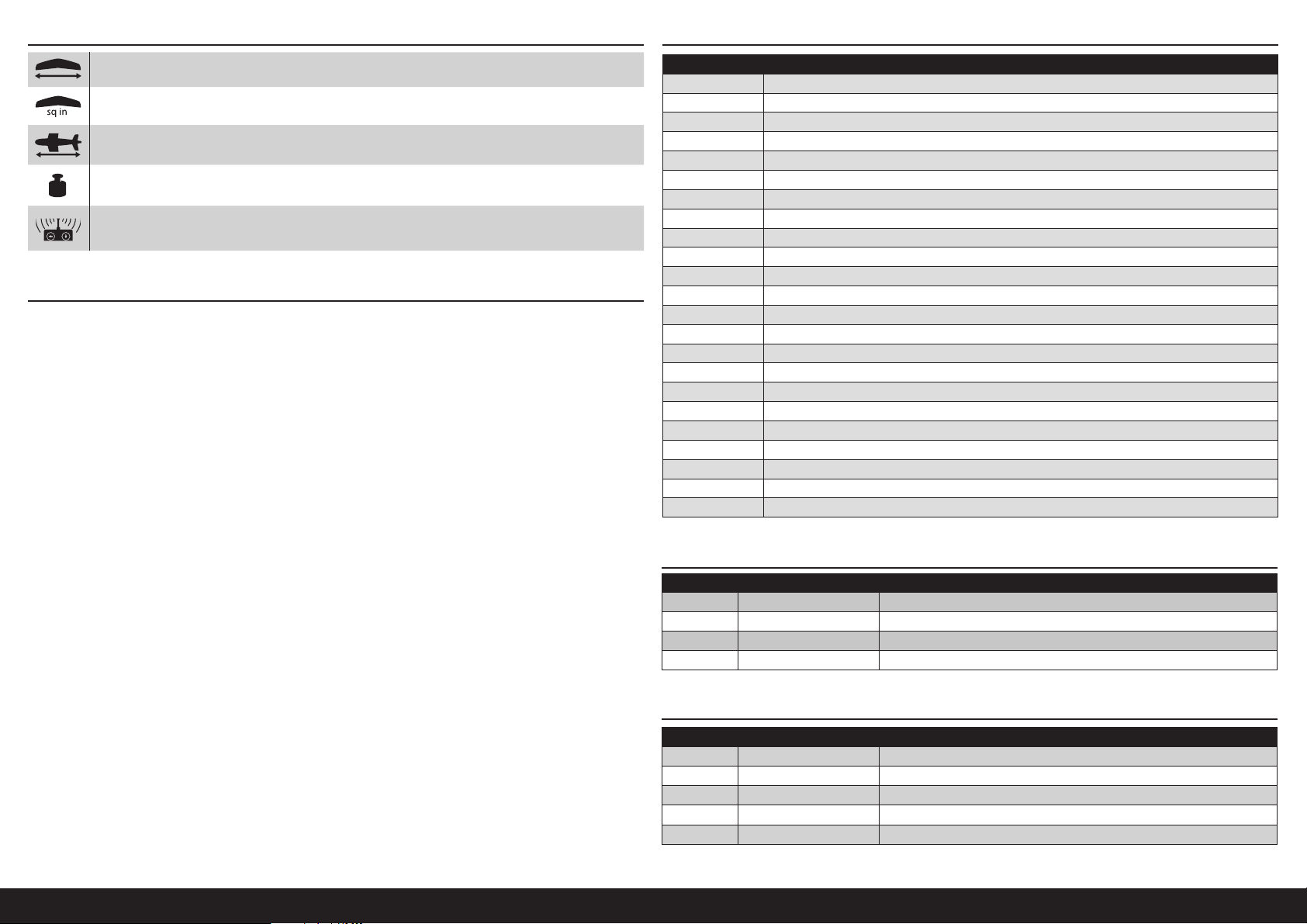
PEZZI DI RICAMBIOSPECIFICHE
561/2 in (1435 mm)
537 sq in (35.65 dm2)
46.18 in (1172 mm)
1569 g senza batteria, 2079 g con la batteria consigliata
5 (o più) canali
INDICE
Avvertimenti E Precauzioni Per La Sicurezza ...............................................................................................................35
Raccomandazioni per operare in sicurezza .................................................................................................................35
Prima di iniziare il montaggio ......................................................................................................................................35
Specifi che ...................................................................................................................................................................36
Pezzi di ricambio .........................................................................................................................................................36
Necessario per completare .........................................................................................................................................36
Parti opzionali ............................................................................................................................................................. 36
Batterie opzionali per grande potenza (per elica 12 x 6) ..............................................................................................37
Attrezzi e adesivi richiesti ...........................................................................................................................................37
Adesivi e attrezzi opzionali .......................................................................................................................................... 37
Precauzioni di montaggio ............................................................................................................................................37
Rimozione delle grinze ................................................................................................................................................37
Controllo dei servo degli alettoni .................................................................................................................................37
Montaggio del carrello di atterraggio ...........................................................................................................................38
Montaggio delle ali .....................................................................................................................................................38
Montaggio di stabilizzatore e deriva ............................................................................................................................38
Montaggio del ricevitore .............................................................................................................................................40
Collegamenti dei servo di equilibratore e timone .........................................................................................................40
Montaggio di cappottatura e batteria ..........................................................................................................................40
Montaggio dell’ala ......................................................................................................................................................41
Montaggio fi nale .........................................................................................................................................................41
Applicazione delle decalcomanie ................................................................................................................................41
BARICENTRO ..............................................................................................................................................................42
Collegamento delle aste di comando ...........................................................................................................................42
Corse dei comandi ......................................................................................................................................................43
Lista Dei Controlli Prima Del Volo ................................................................................................................................43
Controlli Di Volo Giornalieri ..........................................................................................................................................43
Garanzia .....................................................................................................................................................................44
Contatti Per La Garanzia E L’Assistenza .......................................................................................................................45
Pezzo # Descrizione
HAN318001 Fusoliera
HAN318002 Pannelli alari
HAN318003 Set del carrello di atterraggio
HAN318004 Stabilizzatore
HAN318005 Stabilizzatore verticale
HAN318006 Gruppo del ruotino di coda
HAN318007 Coperchio del dado di coda
HAN318009 Miniatura di pilota
HAN318010 Portello con pilota
HAN318011 Carenatura
HAN318012 Vano motore
HAN318013 Ruote
HAN318014 Set dell’asta di spinta
HAN318015 Bulloni alari
HAN318016 Set dei pezzi
HAN318017 Bulloneria in plastica
HAN318018 Set di decalcomanie
HAN318019 Carter carrello d’atterraggio
HAN318020 Elica 14 x 8,5
HAN338008 Tubo dell’ala
SPMSA391 Servo standard
SPMXAE1060C Smart ESC 6S Avian 60 A
SPMXAM2100 Motore 4250-600 Kv 14 poli
NECESSARIO PER COMPLETARE
# richiesto Parte # Descrizione
2 SPMA3050 Prolunga servo standard 76 mm
1 SPMAR637T Ricevitore AR637T 6 CH SAFE e AS3X con telemetria
1 SPMR6775 NX6 6 CH solo trasmittente
1 SPMX50004S30 5000 mAh 4S 14,8 V Smart LiPo 30C IC5
PARTI OPZIONALI
# richiesto Parte # Descrizione
1 APC12060E Elica elettrica sottile, 12 x 6
1 APC14085E Elica elettrica sottile, 14 x 8,5
1 SPMAR8360T Ricevitore AR8360T 8 CH SAFE con telemetria
1
1 SPMR8200 NX8 8 CH DSMX solo trasmittente
SPMR10100 NX10 10 CH solo trasmittente
36IT
Page 37
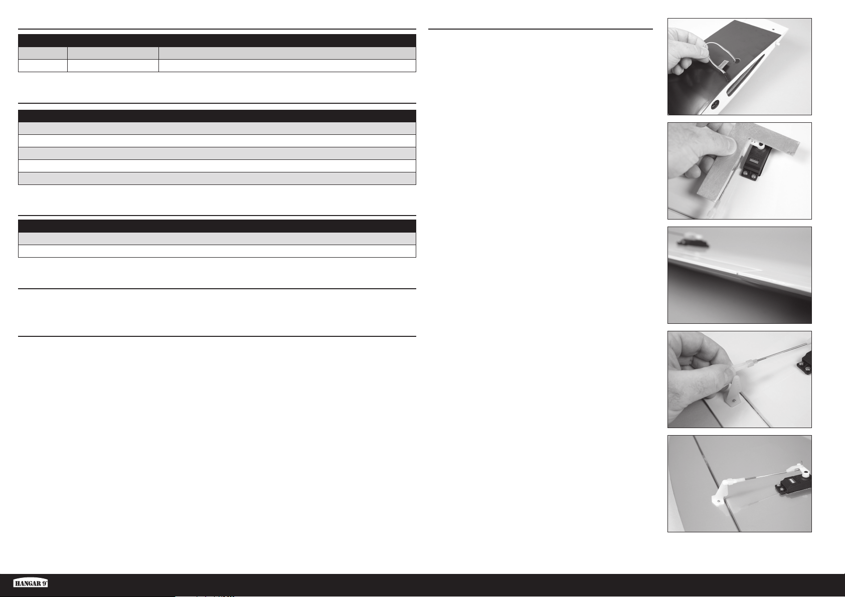
BATTERIE OPZIONALI PER GRANDE POTENZA (PER ELICA 12 X 6)
CONTROLLO DEI SERVO DEGLI ALETTONI
# richiesto Parte # Descrizione
1 SPMX40006S30 4000mAh 6S 22.2V Smart 30C; IC5
1 SPMX50006S50 5000mAh 6S 22.2V Smart 50C; IC5
ATTREZZI E ADESIVI RICHIESTI
Descrizione
Supporto per bilanciamento
Cacciavite a lama piatta: piccolo, grande
Chiave per dadi: 1/4-inch
Cacciavite a croce: #1, #2
Squadretta
ADESIVI E ATTREZZI OPZIONALI
Descrizione
Adesivo siliconico
Sottile CA
PRECAUZIONI DI MONTAGGIO
Durante il montaggio, si consiglia di appoggiare le parti su una superfi cie morbida, per esempio un asciugamano
morbido, in modo da non ammaccare il rivestimento.
RIMOZIONE DELLE GRINZE
Il rivestimento del modello può sviluppare delle grinze durante la spedizione per la cui rimozione può essere necessario
ricorrere a pistola termica (HAN100) e guanto speciale (HAN150) oppure a un ferro apposito per rivestimenti (HAN101)
con la sua calza di protezione (HAN141). Prestare attenzione quando si lavora attorno ad aree con sovrapposizione di
colori per evitarne il distacco. Evitare di scaldare troppo per non separare i colori. Mettere un panno umido fresco sui
colori vicini aiuta a prevenirne la separazione durante la rimozione delle grinze.
1. Tirare i fi li dei servo degli alettoni facendoli passare nei fori
sulla parte superiore dell’ala.
2. Collegare il servo degli alettoni al ricevitore. Centrare stick
e trim degli alettoni. Controllare che l’asta di comando sia a
90° rispetto al braccio del servo. In caso contrario, rimuovere
il braccio del servo e regolare oppure usare il sub-trim se si
usa una radio computerizzata.
3. Controllare l’alettone per assicurarsi che sia allineato con
l’ala.
4. Se l’alettone non è allineato, scollegare la forcella e avvitarla
o svitarla quanto basta per correggere il disallineamento.
Fun Scale PT-19 PNP
5. Completata la regolazione, ricollegare la forcella alla
squadretta di controllo dell’alettone. Far scorrere il fermo in
silicone sopra i bracci della forcella per evitare che possa
sganciarsi dalla squadretta di controllo
Ripetere la procedura per l’altra ala.
37 IT
Page 38
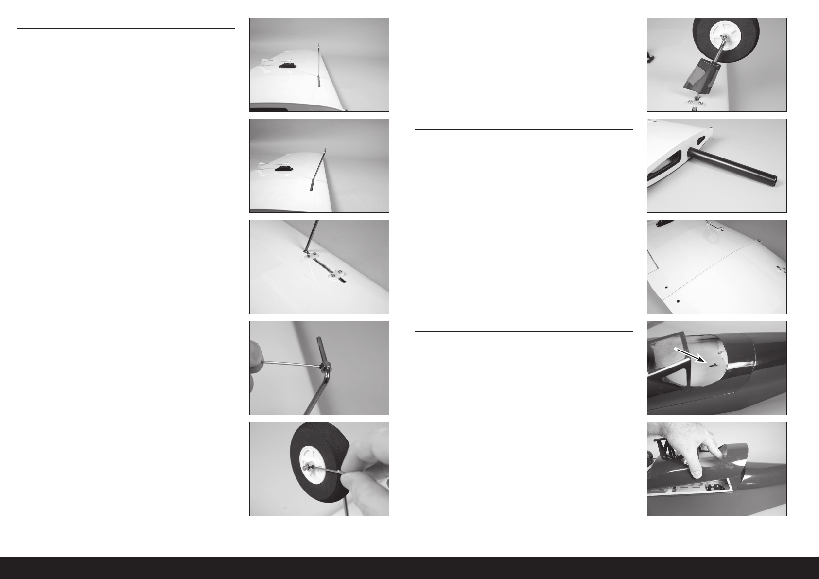
MONTAGGIO DEL CARRELLO DI ATTERRAGGIO
6. Inserire il fi lo del carrello nell’ala. Il carrello di atterraggio
risulta leggermente inclinato in avanti quando installato
correttamente. Il fi lo devono essere a fi lo con il fondo dell’ala
quando installato.
Opzionale
11. Usare un adesivo siliconico fl essibile per attaccare le
carenature al carrello di atterraggio. Utilizzare un nastro a
bassa adesione per tenere le carenature in posizione fi no
all’asciugatura completa dell’adesivo.
MONTAGGIO DELLE ALI
8. Fissare il carrello di atterraggio con due cinghie di nylon e
quattro viti autofi lettanti 3 x 12 mm. Infi lare le viti nei fori
preforati, poi usare un cacciavite a croce #2 per serrare le
viti.
9. Inserire un collarino per ruota sul carrello di atterraggio.
Avvitare una vite di arresto M3 x 4 mm nel collarino della
ruota. Usare la chiave esagonale in dotazione per stringere la
vite di arresto sull’area piatta del carrello di atterraggio più
vicina alla gamba verticale.
12. Far scorrere il tubo alare nella tasca dell’ala. Il tubo scivola
facilmente, non forzarlo più di quanto sia necessario.
13. Far scorrere l’altra ala sul tubo. Le semiali si incastreranno
strettamente e senza spazi vuoti.
MONTAGGIO DI STABILIZZATORE E DERIVA
14. Rimuovere il portello della capottina dalla fusoliera facendo
scorrere in avanti il fermo situato nel cockpit posteriore.
10. Far scorrere la ruota sul carrello di atterraggio, quindi fi ssarla
con un collarino e una vite di fermo M3 x 4 mm.
Opzionale: Utilizzare una piccola quantità di
frenafiletti su ciascuna vite di arresto per evitarne
l’allentamento a causa delle vibrazioni.
15. Sollevare il portello dal retro e rimuoverlo dalla fusoliera.
Riporre in un luogo sicuro.
38IT
Page 39
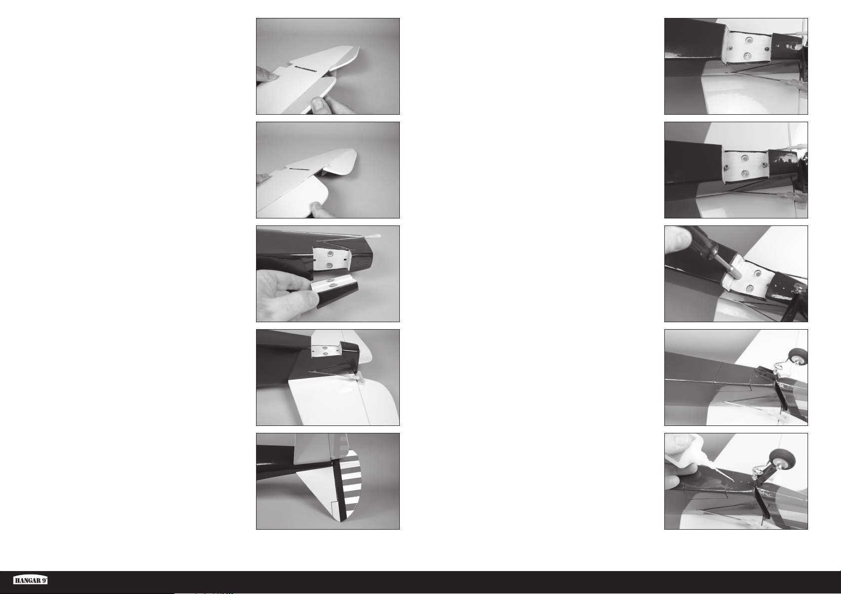
16. Flettere più volte l’equilibratore per tutta la sua ampiezza di
movimento per rodare le cerniere.
21. Far scorrere una rondella #4 su ciascuna delle aste fi lettate.
22. Avvitare i dadi 4-40 sulle aste fi lettate.
18. Rimuovere dalla fusoliera il coperchio inferiore trattenuto
magneticamente. Riporre in un luogo sicuro.
19. Far scorrere lo stabilizzatore nella tasca della fusoliera. La
squadretta di controllo sarà rivolta verso la parte inferiore
della fusoliera. Assicurarsi che lo stabilizzatore sia tutto avanti
e che la tasca nello stabilizzatore sia allineata con quella nella
fusoliera per la deriva.
20. Rodare le cerniere del timone usando lo stesso metodo
seguito per le cerniere dell’elevatore. Far scorrere la deriva
in posizione. Sarà necessario muovere la staffa del ruotino di
coda quando si monta la deriva.
23. Serrare i dadi con una chiave per dadi da 1/4". Non serrare
eccessivamente i dadi per non danneggiare la fusoliera o la
deriva.
24. Rimettere il rivestimento inferiore della fusoliera in posizione
sulla fusoliera.
Opzionale
25. Applicare qualche goccia di colla cianoacrilica in ciascuno
dei tre fori per le viti della staffa del ruotino di coda. Prima di
procedere, assicurarsi che la colla si asciughi del tutto.
Fun Scale PT-19 PNP
39 IT
Page 40
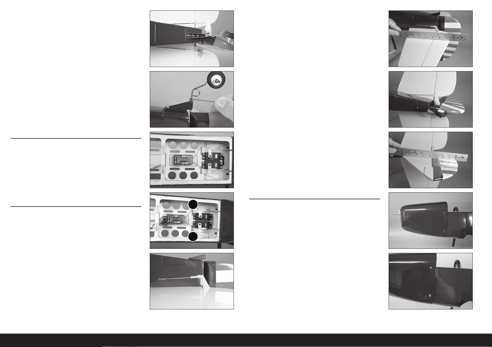
26. Fissare la staffa del ruotino di coda alla fusoliera con tre viti
per lamiera #2 x 5/16". Utilizzare un cacciavite a croce #1 per
serrare le viti.
31. Utilizzare un bordo dritto o una squadretta per controllare
l’allineamento tra equilibratore e stabilizzatore. Il righello
giacerà piatto lungo entrambi se la regolazione è corretta.
Regolare la forcella sull’asta di comando quanto necessario
per allineare l’equilibratore. Assicurarsi di far scorrere il fermo
in silicone sui bracci della forcella per evitare che possa
allentarsi in volo.
27. Infi lare il collarino della ruota sulla staffa del ruotino.
Assicurarsi che ci sia abbastanza spazio per permettere il
libero movimento del timone. Serrare il grano nel collarino
della ruota con una chiave esagonale da 1,5 mm.
MONTAGGIO DEL RICEVITORE
28. Installare il ricevitore nella fusoliera con del nastro biadesivo
in schiuma. Fare riferimento alle istruzioni del ricevitore
per maggiori dettagli sul suo montaggio e sul percorso
dell’antenna.
Utilizzare del nastro trasparente per fissare l’antenna in
modo che non interferisca con il movimento dei servo.
COLLEGAMENTI DEI SERVO DI EQUILIBRATORE E
TIMONE
29. Collegare i servo del timone (1) e dell’equilibratore (2) al
ricevitore. Centrare stick e trim di equilibratore e timone.
Controllare che l’asta di comando sia a 90° rispetto al
braccio del servo. In caso contrario, rimuovere il braccio del
servo e regolare oppure usare il sub-trim se si usa una radio
computerizzata.
32. Collegare la forcella al foro esterno sulla squadretta del
timone.
33. Utilizzare un bordo dritto o una squadretta per controllare
l’allineamento tra timone e deriva. Il righello giacerà piatto
lungo entrambi se la regolazione è corretta. Regolare la
forcella sull’asta di comando quanto necessario per allineare
il timone. Assicurarsi di far scorrere il fermo in silicone sui
bracci della forcella per evitare che possa allentarsi in volo.
MONTAGGIO DI CAPPOTTATURA E BATTERIA
1
2
34. Far scivolare la cappottatura sulla fusoliera.
30. Collegare la forcella al foro esterno sulla squadretta
dell’elevatore.
35. Fissare la capottina usando quattro viti autofi lettanti da 3 x
12 mm e un cacciavite a croce #2. Due viti sono utilizzate su
ciascun lato della cappottatura.
40IT
Page 41
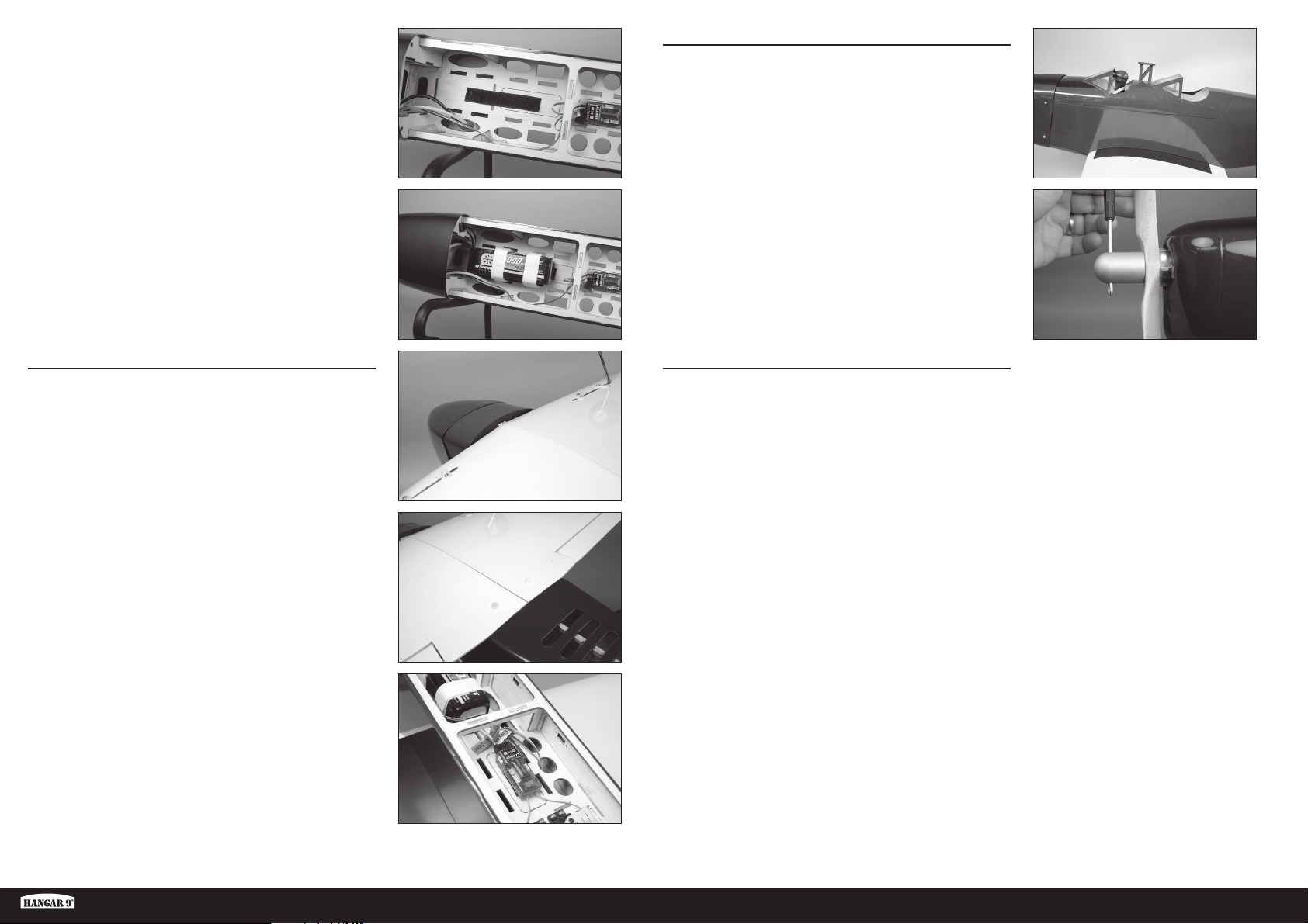
36. Applicare un lato della fascetta a strappo sul supporto della
batteria.
Opzionale: applicare uno strato sottile di colla cianoacrilica
sul vassoio usando un tovagliolo di carta. Lasciare indurire
la colla prima di applicare la fascetta a strappo.
Si raccomanda di applicare la parte a uncini del nastro
a strappo alla cellula e la parte ad asole alla batteria.
MONTAGGIO FINALE
41. Montare il tettuccio sulla fusoliera.
37. Applicare il lato di accoppiamento del nastro a strappo sulla
batteria. Assicurarsi di non coprire le etichette di avvertenza
sulla batteria. Fissare la batteria nella fusoliera con il nastro
a strappo.
Il posizionamento della batteria può essere cambiato
per regolare il centro di gravità. Una volta regolato
il centro di gravità, segnare la posizione della
batteria in modo da poterla riportare nella posizione
corretta quando viene installata dopo la ricarica.
MONTAGGIO DELL’ALA
38. Far scorrere l’ala sulla fusoliera, allineandone la linguetta
con la fessura nella fusoliera. La linguetta si inserirà nella
fusoliera con il bordo d’attacco stretto contro la fusoliera.
39. Fissare l’ala alla fusoliera con i due bulloni ad alette di nylon.
Serrare i bulloni con un cacciavite a lama piatta.
42. Infi lare l’elica sull’albero del motore. Avvitare il dado
dell’ogiva sull’albero motore. Usare una chiave esagonale
fatta passare attraverso il foro del dado dell’ogiva per
stringere il dado sull’albero.
Usare estrema cautela intorno all’elica una volta
installata. Per evitare il rischio di infortuni, trattare il
motore come se fosse "sotto tensione", nel senso che
potrebbe avviarsi bruscamente senza preavviso.
APPLICAZIONE DELLE DECALCOMANIE
43. Applicare le decalcomanie al modello utilizzando come
riferimento le foto sulla confezione. Utilizzare una bomboletta
spray e una goccia di detersivo liquido per piatti o lavavetri
spruzzato in corrispondenza della decalcomania per regolarne
la posizione. Utilizzare un panno di carta come lavavetri per
rimuovere il liquido in eccesso da sotto la decalcomania.
Lasciare riposare il modello durante la notte in modo che il
liquido residuo evapori.
40. Collegare i cavi dei servi degli alettoni al ricevitore.
Fun Scale PT-19 PNP
41 IT
Page 42
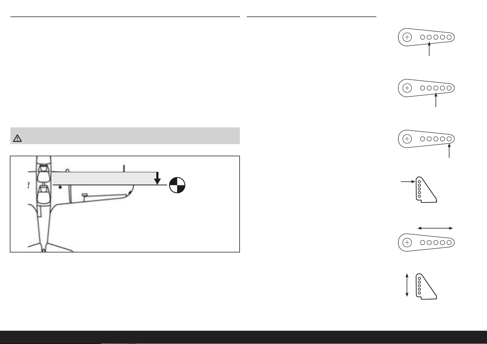
BARICENTRO
Una parte molto importante nella preparazione del modello riguarda il suo bilanciamento.
1. Fissare le ali alla fusoliera. Accertarsi che gli alettoni siano collegati alle giuste prolunghe provenienti dalla
ricevente. Prima di stringere le viti di fi ssaggio dell’ala, verifi care che i fi li non siano rimasti fuori dalla fusoliera.
Prima del bilanciamento è necessario che il modello sia completamente pronto al volo.
2. Il baricentro consigliato per il modello si trova 85 mm dietro il bordo d’attacco dell’ala.
3. Quando si esegue il bilanciamento del modello, assicurarsi sia ben assemblato e pronto per il volo. Tenere l’aereo
capovolto in corrispondenza dei segni presenti sull’ala utilizzando le mani o un supporto disponibile in commercio.
Il baricentro consigliato (CG) è il punto di equilibrio raccomandato per i primi voli. Esso rappresenta un’impostazione
stabile e sicura per esplorare in tutta tranquillità le prestazioni e la guida del modello.
L’intervallo di valori tra 80 mm e 95 mm comprende le impostazioni alle quali il modello è stato testato in volo e che
sono risultate sicure. All’interno di questo intervallo la stabilità e le prestazioni del modello variano leggermente con la
regolazione. Poiché ogni pilota ha il proprio stile e le proprie preferenze, si consiglia di apportare piccole modifi che al
baricentro fi nché non si ottengono le prestazioni desiderate.
ATTENZIONE: prima di andare in volo, bisogna regolare correttamente la posizione del baricentro.
COLLEGAMENTO DELLE ASTE DI COMANDO
Prima di controllare le corse dei comandi, assicurarsi che le aste
di comando siano collegate ai bracci del servo come mostrato per
ottenere la corsa dei comandi corretta.
Equilibratore
Alettoni
Timone
85mm
back from leading
edge at the root
La forcella deve essere collegata al foro esterno della squadretta
di controllo per il timone, l’equilibratore e gli alettoni per ottenere
la corsa dei comandi corretta.
Questi sono i collegamenti raccomandati per le posizioni delle aste
di comando per i primi voli. Le posizioni delle aste di comando
possono essere cambiate per aumentare o ridurre la corsa una
volta che ci si è abituati alle caratteristiche di volo del modello.
Squadrette di controllo
AumentaRiduce
Riduce
Aumenta
42IT
Page 43
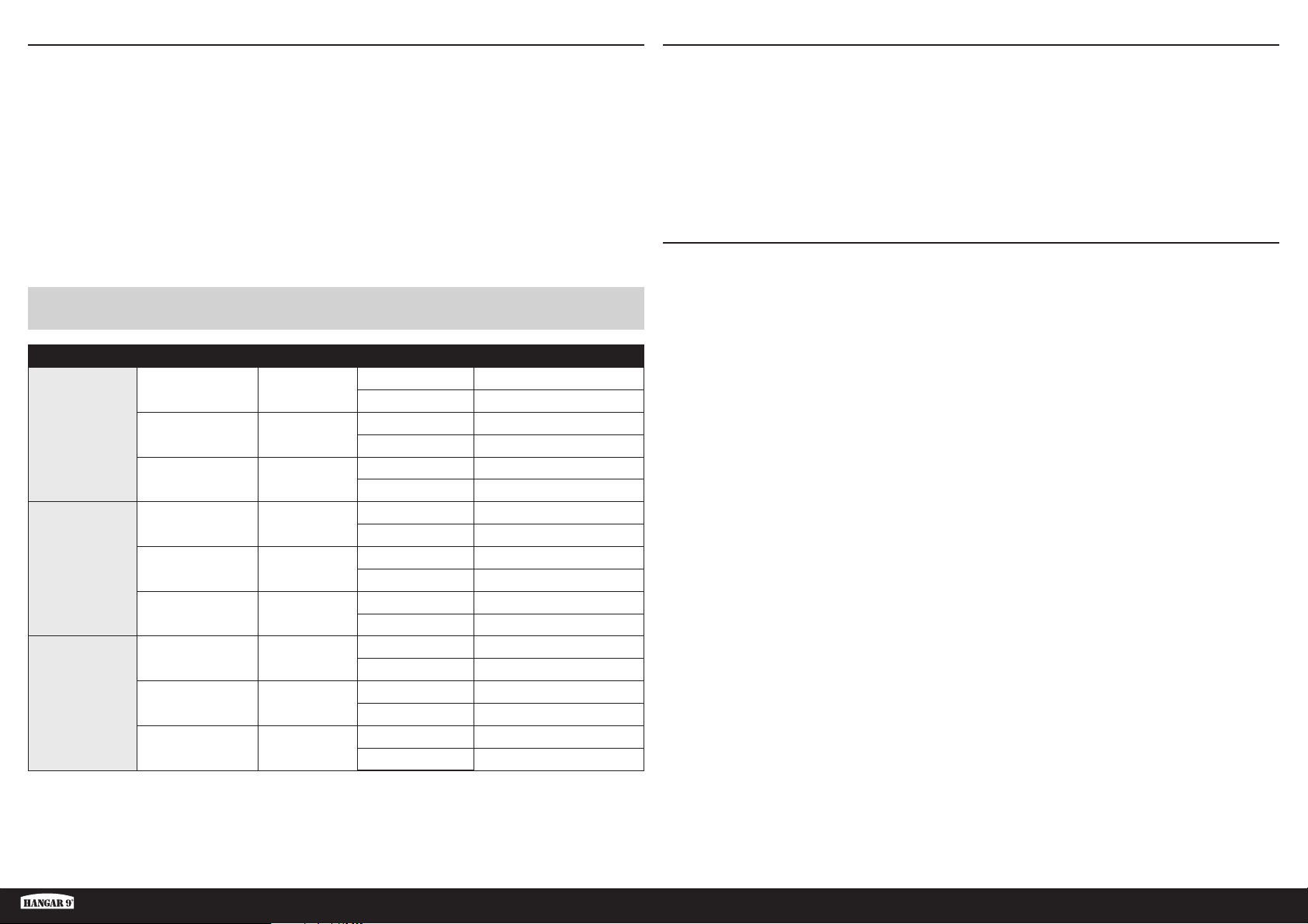
CORSE DEI COMANDI
1. Accendere la trasmittente e la ricevente del modello. Controllare il movimento del timone con il radiocomando.
Quando si sposta lo stick a destra il timone si deve spostare verso destra. Se necessario intervenire sul Reverse
del tramettitore.
2. Controllare il movimento dell’elevatore con il radiocomando. Spostando lo stick dell’elevatore verso il basso del
trasmettitore, l’elevatore sul modello si sposterà in alto.
3. Controllare il movimento degli alettoni con il radiocomando. Spostando lo stick degli alettoni verso destra,
l’alettone destro andrà verso l’alto e quello sinistro verso il basso.
4. Usare un misuratore di corsa per regolare le corse di alettoni, elevatore e timone.
Queste sono le linee guida generali per il volo sportivo e acrobatico suggerite dai nostri test di volo. Si può comunque
provare con ratei più alti o più bassi secondo lo stile di volo preferito.
SI PREGA DI NON AUMENTARE I MOVIMENTI DEI COMANDI SU QUELLI MOSTRATI PRIMA DEL PRIMO VOLO! Questo
modello è molto reattivo al beccheggio e al rollio con piccoli movimenti.
Superfi cie Rateo Esponenziale Direzione Corsa
Verso l’alto 13 mm
Verso il basso 13 mm
Verso l’alto 9 mm
Verso il basso 9 mm
Verso l’alto 7 mm
Verso il basso 7 mm
Verso l’alto 15 mm
Verso il basso 15 mm
Verso l’alto 10,5 mm
Verso il basso 10,5 mm
Verso l’alto 8 mm
Verso il basso 8 mm
Destra 36 mm
Sinistra 36 mm
Destra 24 mm
Sinistra 24 mm
Destra 18 mm
Sinistra 18 mm
Alettoni
Elevatore
Timone
Alto 10%
Medio 5%
Basso 0%
Alto 10%
Medio 5%
Basso 0%
Alto 10%
Medio 5%
Basso 0%
LISTA DEI CONTROLLI PRIMA DEL VOLO
• Caricare la trasmittente, il ricevitore e le batterie del motore. Seguire eventuali istruzioni fornite con il caricabatterie.
Seguire tutte le istruzioni del produttore relative ai componenti elettronici.
• Controllare l’installazione della radio e assicurarsi che tutte le superfi ci di controllo (alettoni, elevatore, timone e fl ap)
si muovano correttamente (cioè nella direzione corretta e con le corse consigliate).
• Controllare tutte le squadrette di controllo, squadrette dei servi e forcelle, per accertarsi che siano ben fi ssate e in
buone condizioni.
• Prima di ogni sessione di volo e specialmente con un modello nuovo, eseguire una prova di portata del
radiocomando. Per ulteriori spiegazioni si veda il manuale del radiocomando.
CONTROLLI DI VOLO GIORNALIERI
• Controllare la tensione della batteria del trasmettitore. Non volare se la tensione è inferiore a quella indicata dal
costruttore; in caso contrario si potrebbe avere un incidente distruttivo.
• Controllare tutti i rinvii, le viti, i dadi e i bulloni prima di ogni giornata di volo. Verifi care che non ci siano impedimenti
nelle corse dei comandi e che tutte le parti siano fi ssate bene.
• Verifi care che le superfi ci mobili si muovano nel verso giusto.
• Eseguire una prova di portata a terra prima di una sessione di volo giornaliera.
• Tutti i cavi dei servocomandi e i connettori dei cablaggi degli interruttori devono essere fi ssati al ricevitore.
Fun Scale PT-19 PNP
43 IT
Page 44

GARANZIA
Periodo di garanzia
Garanzia esclusiva - Horizon Hobby, LLC (Horizon) garantisce che il prodotto acquistato (il “Prodotto”) sarà privo di
difetti relativi ai materiali e di eventuali errori di montaggio alla data di acquisto. Il periodo di garanzia è conforme alle
disposizioni legali del paese nel quale il prodotto è stato acquistato. Tale periodo di garanzia ammonta a 6 mesi e si
estende ad altri 18 mesi dopo tale termine.
Limiti della garanzia
(a) La garanzia è limitata all’acquirente originale (Acquirente) e non è cedibile a terzi. L’acquirente ha il diritto a far
riparare o a far sostituire la merce durante il periodo di questa garanzia. La garanzia copre solo quei prodotti acquistati
presso un rivenditore autorizzato Horizon. Altre transazioni di terze parti non sono coperte da questa garanzia. La prova
di acquisto è necessaria per far valere il diritto di garanzia. Inoltre, Horizon si riserva il diritto di cambiare o modifi care i
termini di questa garanzia senza alcun preavviso e di escludere tutte le altre garanzie già esistenti.
(b) Horizon non si assume alcuna garanzia per la disponibilità del prodotto, per l’adeguatezza o l’idoneità del prodotto a
particolari previsti dall’utente. È sola responsabilità dell’acquirente il fatto di verifi care se il prodotto è adatto agli scopi
da lui previsti.
(c) Richiesta dell’acquirente – spetta soltanto a Horizon, a propria discrezione riparare o sostituire qualsiasi prodotto
considerato difettoso e che rientra nei termini di garanzia. Queste sono le uniche rivalse a cui l’acquirente si può
appellare, se un prodotto è difettoso.
Horizon si riserva il diritto di controllare qualsiasi componente utilizzato che viene coinvolto nella rivalsa di garanzia.
Le decisioni relative alla sostituzione o alla riparazione sono a discrezione di Horizon. Questa garanzia non copre dei
danni superfi ciali o danni per cause di forza maggiore, uso errato del prodotto, un utilizzo che viola qualsiasi legge,
regolamentazione o disposizione applicabile, negligenza, uso ai fi ni commerciali, o una qualsiasi modifi ca a qualsiasi
parte del prodotto.
Questa garanzia non copre danni dovuti ad un’installazione errata, ad un funzionamento errato, ad una manutenzione
o un tentativo di riparazione non idonei a cura di soggetti diversi da Horizon. La restituzione del prodotto a cura
dell’acquirente, o da un suo rappresentante, deve essere approvata per iscritto dalla Horizon.
Limiti di danno
Horizon non si riterrà responsabile per danni speciali, diretti, indiretti o consequenziali; perdita di profi tto o di
produzione; perdita commerciale connessa al prodotto, indipendentemente dal fatto che la richiesta si basa su un
contratto o sulla garanzia. Inoltre la responsabilità di Horizon non supera mai in nessun caso il prezzo di acquisto
del prodotto per il quale si chiede la responsabilità. Horizon non ha alcun controllo sul montaggio, sull’utilizzo o sulla
manutenzione del prodotto o di combinazioni di vari prodotti. Quindi Horizon non accetta nessuna responsabilità per
danni o lesioni derivanti da tali circostanze. Con l’utilizzo e il montaggio del prodotto l’utente acconsente a tutte le
condizioni, limitazioni e riserve di garanzia citate in questa sede.
Qualora l’utente non fosse pronto ad assumersi tale responsabilità associata all’uso del prodotto, si suggerisce di
restituire il prodotto intatto, mai usato e immediatamente presso il venditore.
Indicazioni di sicurezza
Questo è un prodotto sofi sticato di hobbistica e non è un giocattolo. Esso deve essere manipolato con cautela, con
giudizio e richiede delle conoscenze basilari di meccanica e delle facoltà mentali di base. Se il prodotto non verrà
manipolato in maniera sicura e responsabile potrebbero risultare delle lesioni, dei gravi danni a persone, al prodotto o
all’ambiente circostante. Questo prodotto non è concepito per essere usato dai bambini senza una diretta supervisione
di un adulto. Il manuale del prodotto contiene le istruzioni di sicurezza, di funzionamento e di manutenzione del
prodotto stesso. È fondamentale leggere e seguire tutte le istruzioni e le avvertenze nel manuale prima di mettere in
funzione il prodotto. Solo così si eviterà un utilizzo errato e si preverranno incidenti, lesioni o danni.
Domande, assistenza e riparazioni
Il vostro negozio locale e/o luogo di acquisto non possono fornire garanzie di assistenza o riparazione senza previo
colloquio con Horizon. Questo vale anche per le riparazioni in garanzia. Quindi in tale casi bisogna interpellare un
rivenditore, che si metterà in contatto subito con Horizon per prendere una decisione che vi possa aiutare nel più breve
tempo possibile.
Manutenzione e riparazione
Se il prodotto deve essere ispezionato o riparato, si prega di rivolgersi ad un rivenditore specializzato o direttamente ad
Horizon. Il prodotto deve essere imballato con cura. Bisogna far notare che i box originali solitamente non sono adatti
per effettuare una spedizione senza subire alcun danno. Bisogna effettuare una spedizione via corriere che fornisce
una tracciabilità e un’assicurazione, in quanto Horizon non si assume alcuna responsabilità in relazione alla spedizione
del prodotto. Inserire il prodotto in una busta assieme ad una descrizione dettagliata degli errori e ad una lista di tutti
i singoli componenti spediti. Inoltre abbiamo bisogno di un indirizzo completo, di un numero di telefono per chiedere
ulteriori domande e di un indirizzo e-mail.
Garanzia e riparazione
Le richieste in garanzia verranno elaborate solo se è presente una prova d’acquisto in originale proveniente da un
rivenditore specializzato autorizzato, nella quale è ben visibile la data di acquisto. Se la garanzia viene confermata,
allora il prodotto verrà riparato o sostituito. Questa decisione spetta esclusivamente a Horizon Hobby.
Riparazioni a pagamento
Se bisogna effettuare una riparazione a pagamento, effettueremo un preventivo che verrà inoltrato al vostro rivenditore.
La riparazione verrà effettuata dopo l’autorizzazione da parte del vostro rivenditore. La somma per la riparazione dovrà
essere pagata al vostro rivenditore. Le riparazioni a pagamento avranno un costo minimo di 30 minuti di lavoro e in
fattura includeranno le spese di restituzione. Qualsiasi riparazione non pagata e non richiesta entro 90 giorni verrà
considerata abbandonata e verrà gestita di conseguenza.
ATTENZIONE: Le riparazioni a pagamento sono disponibili solo sull’elettronica e sui motori. Le riparazioni a
livello meccanico, soprattutto per gli elicotteri e le vetture RC, sono molto costose e devono essere effettuate
autonomamente dall’acquirente.
10/15
44IT
Page 45
CONTATTI PER LA GARANZIA E L’ASSISTENZA
NOTE DI MONTAGGIO E DI VOLO
Paese di
acquisto
EU
Dichiarazione di Conformità EU
Con la presente, Horizon Hobby, LLC dichiara
che il dispositivo è conforme a quanto segue:
Direttiva Eco-design 1275/2008;
Direttiva RoHS 2 2011/65 / UE;
Direttiva RoHS 3 - Modifi ca 2011/65 / UE allegato II
2015/863;
Il testo completo della dichiarazione di conformità UE è
disponibile al seguente indirizzo internet: https://www.
horizonhobby.com/content/support-render-compliance.
Produttore uffi ciale dell’UE:
Horizon Hobby, LLC
2904 Research Road
Champaign, IL 61822 USA
Importatore uffi ciale dell’UE:
Horizon Hobby, GmbH
Hanskampring 9
22885 Barsbüttel Germany
Horizon Hobby Telefon/Email Adresse Adresse
Horizon Technischer Service
Horizon Hobby GmbH
+49 (0) 4121 2655 100
[email protected]
Hanskampring 9
D 22885 Barsbüttel, Germany
AVVISO RAEE:
Questo dispositivo è marcato ai sensi della
Direttiva europea 2012/19/UE riguardante
i rifi uti di apparecchiature elettriche ed
elettroniche (RAEE). Il simbolo indica che
il prodotto non va smaltito insieme ai rifi uti domestici. Il
prodotto deve essere consegnato agli appositi centri di
raccolta per consentirne il recupero e il riciclaggio.
Fun Scale PT-19 PNP
45 IT
Page 46

BUILDING AND FLYING NOTES • NOTIZEN ZUM AUFBAU UND FLIEGEN • REMARQUES SUR LE MONTAGE ET LE PILOTAGE • NOTE DI MONTAGGIO E DI VOLO
Page 47

BUILDING AND FLYING NOTES • NOTIZEN ZUM AUFBAU UND FLIEGEN • REMARQUES SUR LE MONTAGE ET LE PILOTAGE • NOTE DI MONTAGGIO E DI VOLO
Page 48

© 2022 Horizon Hobby, LLC.
Hangar 9, SAFE, AS3X, DSMX, Avian, IC3, IC5 and the Horizon Hobby logo are trademarks or registered trademarks of Horizon Hobby, LLC.
The Spektrum trademark is used with permission of Bachmann Industries, Inc.
All other trademarks, service marks and logos are the property of their respective owners.
143081 HAN3180 Created 12/2021
 Loading...