

Page 1
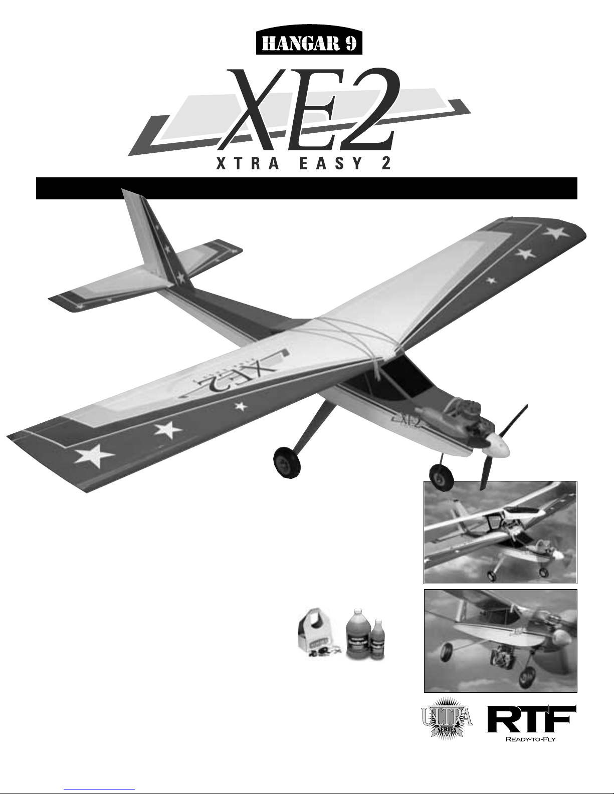
Specifications
• Wingspan: ................................................................................................................ 69in
• Length: ..................................................................................................................... 55in
• Wing Area: ....................................................................................................... 793 sq in
• Weight (approximate): ....................................................................................... 61/4–7 lb
• Engine Supplied: ........................................................... Evolution Trainer Power System
• Ready to fly in less than one hour
• Comes with engine, radio, and control linkages installed
• No glue required for assembly (no smell, no mess)
• Precovered and trimmed in genuine UltraCote
®
• Two Fun options available: Sailplane Launch and Photo OP
(camera not included)
Additional items required to get the Xtra Easy 2 into the air:
• Hangar 9 Start-Up Field Pack, which includes glow plugs, fuel pump,
4-way wrench, glow plug igniter with charger,
Start Stick and tote box (HANSTART)
• Glow Fuel (10% or 15% nitro content recommended) (HAN3109–3115)
TM
TM
Ver. 1.0
INSTRUCTION MANUAL
TM
Page 2
2
Table of Contents
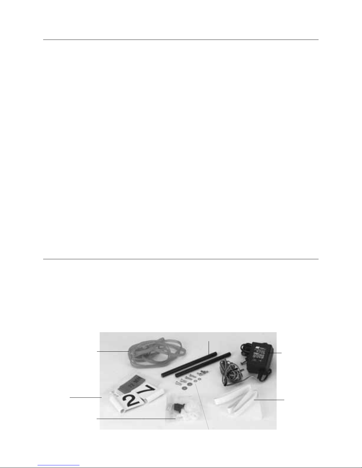
Small Parts
A. #64 Rubber Bands
B. Wing Dowels
C. Transmitter/Receiver Charger
D. Radio Frequency Identifiers
E. Servo Accessories
F. Tail and Landing Gear Hardware
G. Center Wing Tape
Small Parts Layout . . . . . . . . . . . . . . . . . . . . . . . . . . . . . . . . . . . . . . . . . . . . . . . . . . . . . . . . . . . . . . . . . . . . . . . . . . . . . . . . . . . 2
Large Parts Layout . . . . . . . . . . . . . . . . . . . . . . . . . . . . . . . . . . . . . . . . . . . . . . . . . . . . . . . . . . . . . . . . . . . . . . . . . . . . . . . . . . . 3
Assembly Diagram . . . . . . . . . . . . . . . . . . . . . . . . . . . . . . . . . . . . . . . . . . . . . . . . . . . . . . . . . . . . . . . . . . . . . . . . . . . . . . . . . . . 4
Section 1: Assemble the Wing . . . . . . . . . . . . . . . . . . . . . . . . . . . . . . . . . . . . . . . . . . . . . . . . . . . . . . . . . . . . . . . . . . . . . . . . . . 6
Section 2: Install the Main Landing Gear and Wing Hold-Down Dowels . . . . . . . . . . . . . . . . . . . . . . . . . . . . . . . . . . . . . . . . . . . . 7
Section 3: Install the Tail Surfaces . . . . . . . . . . . . . . . . . . . . . . . . . . . . . . . . . . . . . . . . . . . . . . . . . . . . . . . . . . . . . . . . . . . . . . . 8
Section 4: Installing the Propeller on the Evolution Trainer Engine . . . . . . . . . . . . . . . . . . . . . . . . . . . . . . . . . . . . . . . . . . . . . . . . 9
Final Assembly . . . . . . . . . . . . . . . . . . . . . . . . . . . . . . . . . . . . . . . . . . . . . . . . . . . . . . . . . . . . . . . . . . . . . . . . . . . . . . . . . . . . 11
Control Checks . . . . . . . . . . . . . . . . . . . . . . . . . . . . . . . . . . . . . . . . . . . . . . . . . . . . . . . . . . . . . . . . . . . . . . . . . . . . . . . . . . . . 12
Preflight Checks at the Field . . . . . . . . . . . . . . . . . . . . . . . . . . . . . . . . . . . . . . . . . . . . . . . . . . . . . . . . . . . . . . . . . . . . . . . . . . 13
Evolution Trainer Power System . . . . . . . . . . . . . . . . . . . . . . . . . . . . . . . . . . . . . . . . . . . . . . . . . . . . . . . . . . . . . . . . . . . . . . . . 13
Starting the Evolution Engine . . . . . . . . . . . . . . . . . . . . . . . . . . . . . . . . . . . . . . . . . . . . . . . . . . . . . . . . . . . . . . . . . . . . . . . . . . .15
Flying your Xtra Easy Trainer . . . . . . . . . . . . . . . . . . . . . . . . . . . . . . . . . . . . . . . . . . . . . . . . . . . . . . . . . . . . . . . . . . . . . . . . . . 17
Engine Adjustments . . . . . . . . . . . . . . . . . . . . . . . . . . . . . . . . . . . . . . . . . . . . . . . . . . . . . . . . . . . . . . . . . . . . . . . . . . . . . . . . . .17
AMA Safety Code . . . . . . . . . . . . . . . . . . . . . . . . . . . . . . . . . . . . . . . . . . . . . . . . . . . . . . . . . . . . . . . . . . . . . . . . . . . . . . . . . . . 18
Glossary of Terms . . . . . . . . . . . . . . . . . . . . . . . . . . . . . . . . . . . . . . . . . . . . . . . . . . . . . . . . . . . . . . . . . . . . . . . . . . . . . . . . . . 20
Miscellaneous Package
A. #64 Rubber Bands
D. Radio Frequency
Identifiers
E. Servo Accessories
F. Tail and Landing Gear Hardware
G. Center
Wing Tape
C. Transmitter/
Receiver Charger
B. Wing Dowels
Page 3
3
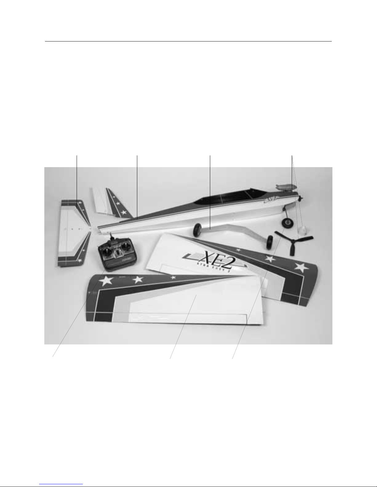
Large Parts
1. Tail Assembly
2. Fuselage
3. Main Landing Gear
4. Engine (Evolution Trainer Power System)
5. Transmitter (JR 421EX)
6. Wings
7. Nose Gear
6. Wings 7. Nose Gear
3. Main Landing Gear2. Fuselage
4. Engine
(Evolution Trainer
Power System)1. Tail Assembly
5. Transmitter (JR 421EX)
Page 4
4
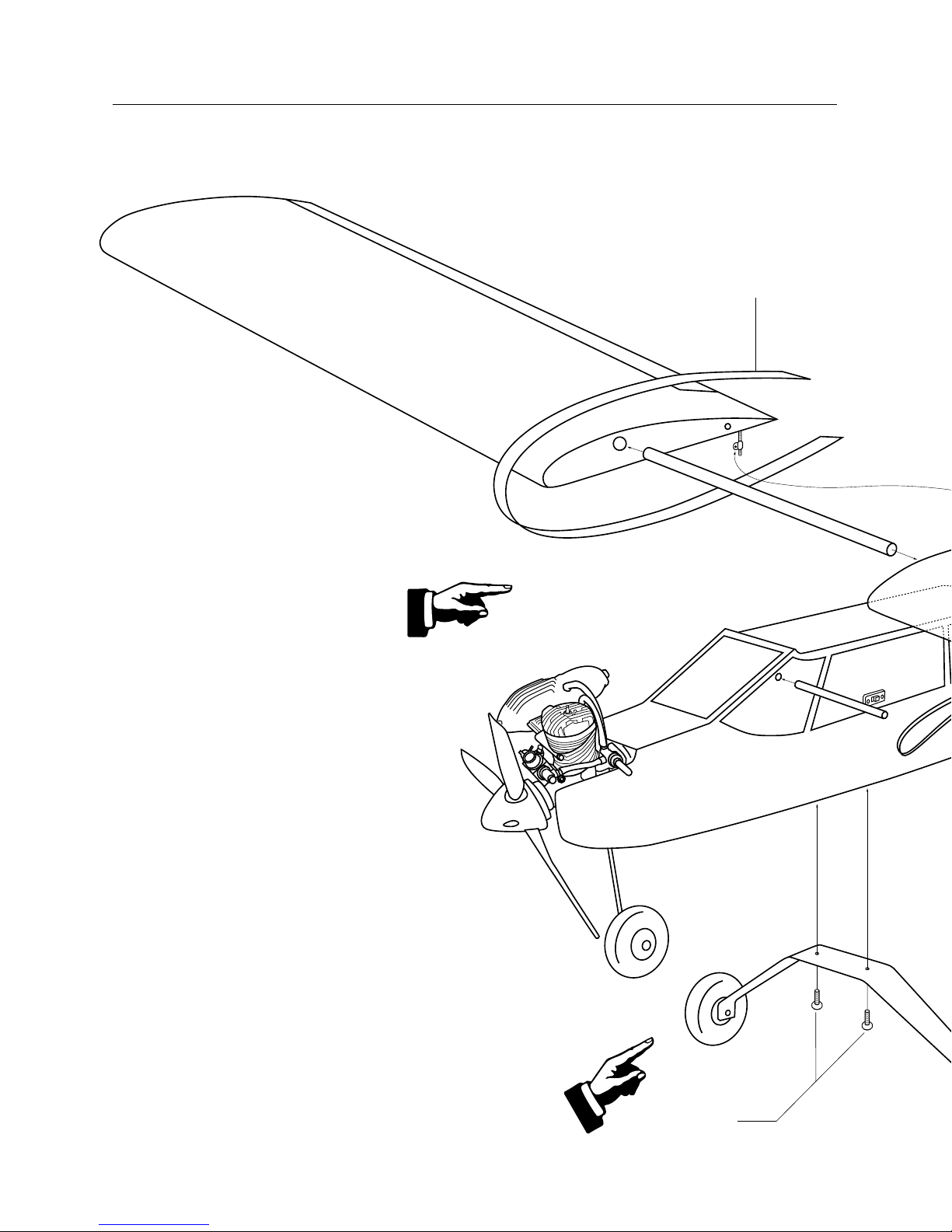
Assembly Diagram (For reference only)
Please carefully read through the entire instruction manual
before beginning assembly of your Xtra Easy 2™
Ready-To-Fly (RTF) kit.
1. Assemble the wing
2. Mount the main landing gear
Tape Strip
Short Screws
Page 5
5
3. Install the
tail surfaces
Rubber Bands (5 per side) to hold wing
Small Washers
Long Screws
Large Washers
Page 6
6
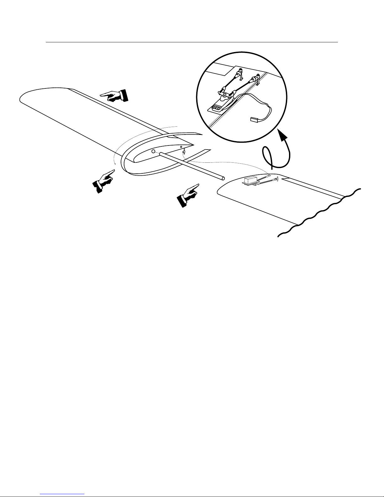
Section 1: Assemble the Wing
Carefully remove the contents of the Xtra Easy 2™ RTF kit. It is
recommended that you charge the transmitter and receiver batteries for 24 hours prior to flying your model.
Step 1. Remove each wing from its protective plastic bag.
Remove the pieces of tape that hold the ailerons in place for
shipping. The hinges in the Xtra Easy 2 Trainer have already
been glued in place during manufacturing. Check the ailerons
for freedom of movement by flexing them up and down several
times.
Step 2. Locate the aluminum wing tube and carefully slide it
into the opening in one of the wing halves. The fit may be snug,
so use a twisting motion while inserting the tube. There is a
short metal pin located near the trailing edge that will key into
the opposite wing panel and keep the wing from rotating around
the wing tube. Carefully slide the other wing half onto the wing
tube. Align the metal pin with its hole and press the wing
panels together.
Step 3. Locate the wing joiner tape and apply it to the top and
bottom of the wing along the joint. Start at the top of the trailing
edge and wrap it around the front of the wing and to the bottom
trailing edge.
Step 4. The aileron servo lead has been tied around the linkage for shipment. Untie the servo lead to free up the aileron
linkage. Note that the lead has been labeled with a piece of
tape; do not remove this tape. One of the aileron linkages has
already been connected to the aileron and secured with a small
piece of tubing (clevis keeper). This is done to prevent the
clevis from opening during flight.
Connect the other aileron linkage to the aileron and snap the
clevis in place. Slide the clevis keeper over the clevis to secure
the linkage to the aileron.
Step 1-3
Wrap supplied
clear tape around
the center joint.
Step 1-1
Remove shipping tape.
Step 1-2
Slide both wing panels onto
the metal tube.
Step 1-4
Attach clevis.
Bottom view of wing
Page 7
7
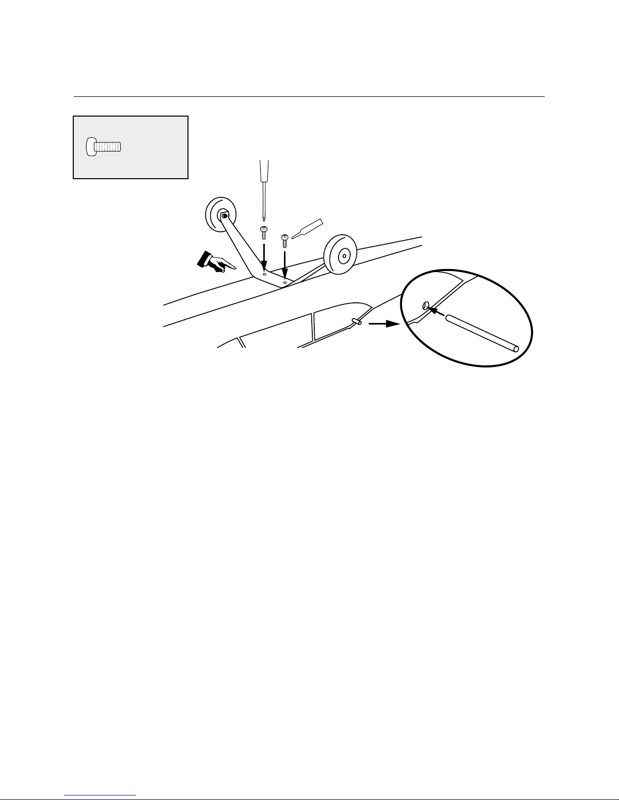
Section 2. Installing the Main Landing Gear and
Wing Hold-Down Dowels
Step 1. Locate the aluminum main landing gear. The wheels
have already been attached. You should have two screws
remaining from the hardware package. Apply a drop of threadlock to each screw. Then, insert them through the holes in the
landing gear and attach the landing gear to the fuselage.
Step 2. Locate the two wing hold-down dowels and insert
one into each of the two holes located in the fuselage, using
a careful twisting motion to install. The dowels should be
positioned so an equal amount is projecting from either side
of the fuselage.
Step 2-1
Mount landing gear to fuselage
with the two screws provided.
Apply threadlock to threads of the screws prior
mounting to landing gear.
Short Screw
Step 2-2
Page 8
8
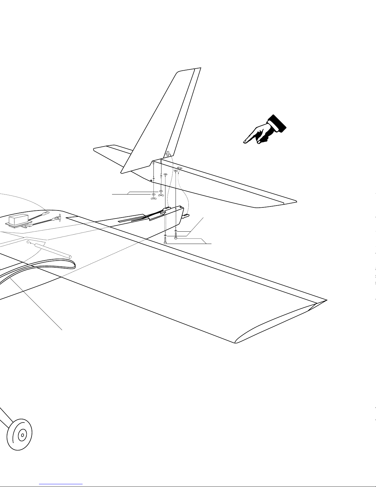
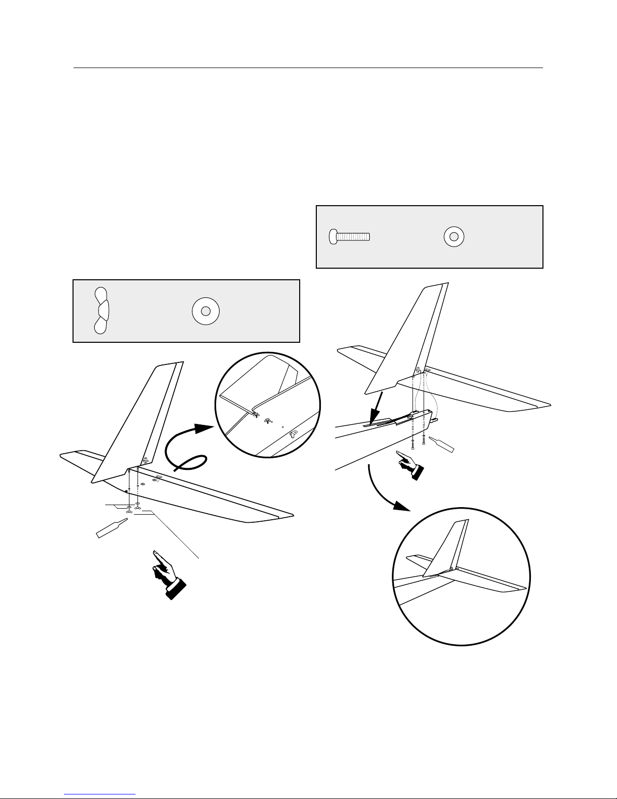
Section 3: Installing the Tail Assembly
Locate the horizontal stabilizer and vertical stabilizer
assemblies. The rudder and elevator have been prehinged
at the factory and the control horns are also attached.
Remove the shipping tape holding the rudder and elevator
in place. Check both the rudder and elevator for freedom of
movement.
Step 1. The vertical stabilizer has threaded rods in the bottom
that secure it to the horizontal stabilizer. Insert the threaded
rods through the pre-drilled holes in the horizontal stabilizer.
Secure them together using the two large washers and two wing
nuts. Be sure to use a drop of threadlock on the threaded rods
before tightening the wing nuts.
Step 2. Slide the tail assembly into the slot in the rear of
the fuselage; making sure the rudder pushrod is on top of the
horizontal stabilizer. Use the two long screws and two small
washers to secure the tail assembly to the fuselage. There are
holes in the bottom of the fuselage to access the screw locations. Place a drop of threadlock on the screws before installing
the screws.
Hint: Use a magnetic screwdriver when installing
the screws.
Attach the vertical stabilizer to the
horizontal stabilizer using washer
and wing nut.
Apply threadlock
to the threaded
rods before
installing wing
nuts.
Large
Washer
Wing Nut
Large Washer
Wing Nut
Step 3-1
Slide tail assembly into slot
at fuselage rear.
Apply threadlock to the
screws before installing.
Step 3-2
Small Washer
Long Screw
Page 9

9
Section 4: Installing the Propeller on the
Evolution Trainer Engine
Step 3. Connect the rudder and elevator pushrod clevises to
the pre-installed control horns. Install the clevises into the hole
furthest away from the control surface (see illustration). Secure
each clevis to the control horn by snapping the clevis pin into
the hole. To prevent the clevises from accidentally opening in
flight make sure the clevis keeper is slid up onto the clevis.
Step 1. Remove the prop nut and washer from the Evolution
engine, noting the position of the washer and flywheel.
Step 2. Locate the spinner and three self-tapping screws
included in your Xtra Easy 2™ RTF kit.
Clevis Keeper
Clevis Keeper
Step 3-3
The rudder pushrod
is positioned above
the horizontal stabilizer.
Page 10

10
Section 4: Installing the Propeller on the
Evolution Trainer Engine (continued)
Step 3. With the flywheel in place, install the spinner back
plate onto the engine as shown.
Note: The flywheel is keyed in place onto the engines
crankshaft and should be tight against the front engine
bearing.
Step 4. Slide the propeller onto the engine with the molded
“E” facing forward as shown.
Step 5. Install the prop washer and prop nut removed in
Step 1. Make sure to position the beveled edge of the washer
forward.
Step 6. Using an adjustable wrench, tighten the prop nut
while holding the propeller in place.
Warning: The propeller must be securely tightened
before attempting to run your evolution engine. Be sure
to check the security of the propeller before each flying
session.
Note: The propeller must be positioned to allow the
spinner cone to fit into the slots in the back plate. Test
fit the spinner cone before attempting to install the selftapping screws of the spinner.
Page 11

11
Section 4: Installing the Propeller on the
Evolution Trainer Engine (continued)
Final Assembly
Step 7. Using a Phillips head screwdriver, secure the spinner
cone in place with the three self-tapping screws provided.
Plug the aileron servo connector into the connector marked
“aileron” located in the fuselage. This will connect the aileron
servo in the wing to the aileron channel of your receiver.
Temporarily attach the wing to the fuselage by stretching a rubber band from wing hold-down dowels starting at the leading
edge of the wing back to the trailing edge of the wing. For now,
use just two rubber bands to mount the wing in position.
Aileron
Charger
Page 12

12
Control Checks
The correct servo directions are pre-adjusted, but it’s a good
idea to confirm the correct direction. After charging the transmitter and receiver batteries per the instruction included with
the radio, turn on the transmitter and airplane and check that
the controls are moving in the correct direction, as per the
illustrations below.
Elevator: Moving the
right stick down should
cause the elevator to
move upward. Pushing
the right stick up will
cause the elevator to
move down.
Ailerons: Moving the
right stick to the right
should move the right
aileron up and the left
aileron down. Moving the
stick in the opposite
direction will give the
opposite result.
Rudder: Moving the left
stick to the right should
move the rudder to the
right. Moving the stick to
the left moves the rudder
to the left.
Throttle: Look into the
carburetor. With the throttle (left stick) in the upper
position, the carburetor
should be fully open.
With the throttle stick in
the lower position and
the trim lever centered
the carburetor should be
1/16” open.
It is very important that you make sure the control surfaces
(elevator, ailerons and rudder) are at 0 degrees when the transmitter control sticks and trim levers are centered. Turn on your
transmitter and receiver. Make sure the rudder, elevator and
aileron sticks are centered and the trim levers are centered. Use
a ruler to place against the control surfaces to see if there are
any deflections from the center (0 degrees).
Threading the clevis in or out on the control rod makes adjustments to the control surfaces. Threading in causes the surface
to move toward the rod. Threading out causes the surface to
move away from the rod. Set the control surfaces, elevator,
ailerons and rudder to 0 degrees.
Reconnect the clevises to the outer hole of the control horn of
the rudder and elevator control horns. Make sure that the clevis
keepers are in place.
0°
ELEVATOR
AILERONAILERON
RUDDER
CARBURETOR
Full open
1/16”
Page 13

13
Preflight Checks at the Field
Important: Be sure your batteries are fully charged,
per the instructions included with your radio system.
Before each flight, check the screws and nuts that secure the
metal plate holding the motor in place on the motor mount.
Also check the clevises of each control surface for security and
presence of a clevis keeper.
Perform a ground range check before each day’s flying. Proceed
as follows:
1. Turn the transmitter on. Do not extend the transmitter
antenna.
2. Turn the model on.
3. Slowly walk away from the model while moving the control
surfaces. The aircraft should function properly at a distance of
75–100 feet.
4. Make sure all trim levers on the transmitter are in the proper
position.
5. Make sure all servos and switch harness plugs are secure in
the receiver.
The Evolution Trainer Power System has been specifically
designed with the first time pilot in mind. The engine and
special 3-bladed propeller have been designed to give your Xtra
Easy 2™ the optimum performance for training new RC pilots.
The engine is designed for easy starting and reliable idle to give
you confidence in your equipment allowing you to concentrate
on improving your piloting skills.
Benefits
Meets AMA noise standards
3-bladed propeller produces lower noise level than standard
10 x 6 prop
Baffle in muffler lowers noise even more
Smaller speed envelope
The new 3-bladed prop design has a lower top speed, so overspeeding the model is less likely. This will give the beginner
more reaction time while still providing lots of power to climb
out of bad situations.
Preset needle settings
Ready to run out of the box with no break-in period
Needle Valve limiters
Make it impossible for beginners to adjust the needles valves
wrong to the point that the engine will not run
User-friendly
Easy to start from first try with super reliable idle and
no-break-in needed
Warning: Before operating the Evolution Alpha
Power System, read and follow all safety
points. A rotating propeller can cause serious
personal injury.
Follow these instructions carefully! If this is the first time you
have run a model airplane engine we recommend that you seek
the help of an experienced modeler. Your local hobby shop can
put you in contact with the flying club in your area.
Evolution Trainer Power System
The Evolution Trainer
Power System.
Engineered for ease...
first flight, every flight.
Page 14

14
Evolution Trainer Power System (continued)
Before using, remove any flashing along the edges of the
propeller by scraping it with a sharp knife.
Only use a “chicken stick” or electric starter to start the engine.
Only make adjustments to the carburetor from behind the
engine.
Keep spectators at least 20 feet away and out of the path of a
rotating propeller.
Wear safety glasses and hand protection when operating model
engines. Do not permit any objects to touch a turning propeller.
Remain clear of the propeller plane of rotation.
20 feet
Page 15

15
Evolution Trainer Power System (continued)
Starting the Evolution Engine
To stop the engine, cut off the fuel and air supply by moving
the throttle stick and trim lever down to close the carburetor.
Do not stop the propeller with your hand or other object.
Inspect the propeller after each flight; discard any propeller that
has nicks scratches, or any other visible defect. Do not repair,
alter or in any way modify a propeller. Replacement propellers
are available through your local hobby retailer (EVOE100P).
Field Equipment Needed
The following are included in the Hangar 9®Start-Up Field
pack (HANSTART)
Sturdy cardboard construction Tote Box
Manual fuel pump
Two Hangar 9 glow plugs
4-way wrench
Rechargeable glow driver with charger
Chicken stick
Other Items Needed (not included in Start-Up
Field Accessory pack)
Fuel, 10 to 15% nitro content (Cool Power or Powermaster
recommended)
Electric Starter (optional)
Step 1. Fill the fuel tank with the proper fuel. We recommend
10% or 15% Nitro content such as Cool Power or Powermaster
fuel. Fill the tank by connecting the fuel pump to the line that is
connected to the remote needle valve assembly. Disconnect the
fuel line attached to the pressure fitting of the muffler; your tank
is full when fuel begins to run out of the pressure line. Reconnect the fuel lines to the needle valve assembly and muffler.
Note: It is very important to reconnect the fuel lines to
the correct fitting. If they are reconnected incorrectly the
engine will not run properly.
Page 16

16
Starting the Evolution Engine (continued)
Step 2. To prime your engine, first turn on your transmitter
and then your receiver. Move the throttle to full open and place
your finger over the carburetor opening. Turn the propeller over
by hand six full turns thus priming the engine. Move the throttle
stick full down to idle.
Caution: Always have a helper hold your plane when
starting.
Step 3. Move the throttle trim lever to the middle position.
Place the glow driver on the glow plug and using a start stick
turn the propeller counter clockwise through the compression
stroke. You should feel a bump against the start stick. When
you feel the bump, flip the propeller counter clockwise to start
the engine. Repeat the process if the engine does not start.
Step 4. Allow the engine to idle for 30 seconds. Adjust the
trim lever if necessary to achieve a constant idle.
Note: The flywheel will allow the Evolution engine to
idle reliably at incredibly low speeds. With the glow
driver still attached advance the throttle to full throttle
and then back to idle. Remove the glow driver.
Step 3 photo
Page 17

17
Engine Adjustments
In some conditions due to high altitudes, extreme temperatures,
etc, it may be necessary to slightly adjust the idle and highspeed needle valves. The high- and low-speed needles have
limiters that prevent over adjustment.
If your engine starts from the above procedure but won’t reliably
continue to run with the glow driver removed, follow the steps
below.
Low-Speed Needle Adjustment
Start the engine using the above procedure and leave the glow
driver attached. Allow the engine to idle for 30 seconds, then
pinch and hold the fuel line, cutting off the fuel flow.
Correct: If the low-speed needle adjustment is correct, the
engine increase in rpm slightly (about 300 rpm) and then die.
Too Rich: If the engine rpm increases a lot (500 rpm or
greater) the low-speed needle must be leaned or turned clockwise.
Too Lean: If the engine doesn’t increase in rpm and simply
dies, the low-speed needle must be richened or turned counter
clockwise.
High-Speed Needle Adjustment
With the engine running from Step 1 above, advance the throttle
to full throttle while a helper securely holds your airplane.
Carefully pinch and hold the fuel line, cutting off the fuel flow.
Correct: If the high-speed needle adjustment is correct, the
engine will increase rpm slightly (about 500 rpm) and then die.
Too Rich: If the engine increases a lot (1,000 rpm or greater)
the high-speed needle is too rich and must be leaned or turned
clockwise.
Too Lean: If the engine doesn’t increase rpm and simply dies,
the high-speed needle is too lean and must be richened or
turned counterclockwise.
High-Speed
Needle Adjustment
Low-Speed Needle
Adjustment
Flying the Xtra Easy 2 Trainer
For first-time pilots, the thought of flying their Xtra Easy 2™
Trainer through loops, rolls, and perfect three-point landings
can be thrilling. Learning to fly, however, takes time, patience,
and most importantly, a good instructor. If you’re a first-time
pilot, don’t try to fly your model without an instructor. Seek an
experienced instructor. Your local hobby shop can put you in
touch with an instructor in your area who can fly and trim your
Xtra Easy Trainer, and then give you your first chance on the
“sticks” with very little risk of damage to the airplane. We cannot over emphasize the importance of having a qualified
instructor to help you through your first flights.
The JR radio system has a built-in trainer system or “buddy
box” option. The transmitter can be used with any JR transmitter and a trainer cord (JRPA130). Use of the “buddy box” for the
first few flights is highly recommended.
More experienced pilots will find the Xtra Easy 2 to be a confidence-inspiring airplane. Its super stable, and slow flight characteristics make pinpoint landings easy as pie. At full throttle,
the Xtra Easy 2 Trainer is more than capable of most sport aerobatics maneuvers. The self-righting stability of the model also
makes it one of the easiest airplanes you’ll ever fly.
Page 18

AMA SAFETY CODE
18
2003 Official AMA National Model Aircraft Safety Code
Effective January 1, 2003
Model Flying MUST be in accordance with this Code in order
for AMA Liability Protection to apply.
GENERAL
1) I will not fly my model aircraft in sanctioned events, air
shows, or model flying demonstrations until it has been proven
to be airworthy by having been previously, successfully flight
tested.
2) I will not fly my model higher than approximately 400 feet
within 3 miles of an airport without notifying the airport operator. I will give right-of-way and avoid flying in the proximity
of full-scale aircraft. Where necessary, an observer shall be
utilized to supervise flying to avoid having models fly in the
proximity of full-scale aircraft.
3) Where established, I will abide by the safety rules for the flying site I use, and I will not willfully and deliberately fly my
models in a careless, reckless and/or dangerous manner.
4) The maximum takeoff weight of a model is 55 pounds,
except models flown under Experimental Aircraft rules,
5) I will not fly my model unless it is identified with my name
and address or AMA number, on or in the model. (This does
not apply to models while being flown indoors.)
6) I will not operate models with metal-bladed propellers or
with gaseous boosts, in which gases other than air enter their
internal combustion engine(s); nor will I operate models with
extremely hazardous fuels such as those containing tetranitromethane or hydrazine.
7) I will not operate models with pyrotechnics (any device that
explodes, burns, or propels a projectile of any kind) including,
but not limited to, rockets, explosive bombs dropped from
models, smoke bombs, all explosive gases (such as hydrogen
filled balloons), ground mounted devices launching a projectile.
The only exceptions permitted are rockets flown in accordance
with the National Model Rocketry Safety Code or those permanently attached (as per JATO use); also those items authorized
for Air Show Team use as defined by AST Advisory Committee
(document available from AMA HQ). In any case, models using
rocket motors as a primary means of propulsion are limited to a
maximum weight of 3.3 pounds and a G series motor. Note:( A
model aircraft is defined as an aircraft with or without engine,
not able to carry a human being.)
8) I will not consume alcoholic beverages prior to, nor during,
participation in any model operations.
9) Children under 6 years old are only allowed on the flight line
as a pilot or while under flight instruction.
RADIO CONTROL
1) I will have completed a successful radio equipment ground
range check before the first flight of a new or repaired model.
2) I will not fly my model aircraft in the presence of spectators
until I become a qualified flier, unless assisted by an experienced helper.
3) At all flying sites a straight or curved line(s) must be established in front of which all flying takes place with the other side
for spectators. Only personnel involved with flying the aircraft
are allowed at or in the front of the flight line. Intentional flying
behind the flight line is prohibited.
4) I will operate my model using only radio control frequencies
currently allowed by the Federal Communications Commission.
(Only properly licensed Amateurs are authorized to operate
equipment on Amateur Band frequencies.)
5) Flying sites separated by three miles or more are considered
safe from site-to site interference, even when both sites use the
same frequencies. Any circumstances under three miles separation require a frequency management arrangement which may
be either an allocation of specific frequencies for each site or
testing to determine that freedom from interference exists.
Allocation plans or interference test reports shall be signed by
the parties involved and provided to AMA Headquarters.
Documents of agreement and reports may exist between (1) two
or more AMA Chartered Clubs, (2) AMA clubs and individual
AMA members not associated with AMA Clubs, or (3) two or
more individual AMA members,
6) For Combat, distance between combat engagement line and
spectator line will be 500 feet per cubic inch of engine displacement. (Example: .40 engine = 200 feet.); electric motors
will be based on equivalent combustion engine size. Additional
safety requirements will be per the RC Combat section of the
current Competition Regulations.
7) At air shows or model flying demonstrations a single
straight line must be established, one side of which is for
flying, with the other side for spectators.
8) With the exception of events flown under AMA Competition
rules, after launch, except for pilots or helpers being used, no
powered model may be flown closer than 25 feet to any person.
9) Under no circumstances may a pilot or other person touch a
powered model in flight.
Page 19

19
AMA SAFETY CODE (continued)
Organized RC Racing Event
10) An RC racing event, whether or not an AMA Rule Book
event, is one in which model aircraft compete in flight over a
prescribed course with the objective of finishing the course
faster to determine the winner.
A. In every organized racing event in which contestants, callers and officials are on the course:
1. All officials, callers and contestants must
properly wear helmets, which are OSHA, DOT,
ANSI, SNELL or NOCSAE approved or comparable standard while on the racecourse.
2. All officials will be off the course except for
the starter and their assistant.
3."On the course" is defined to mean any area
beyond the pilot/staging area where actual flying takes place.
B. I will not fly my model aircraft in any organized racing event which does not comply with paragraph A
above or which allows models over 20 pounds unless
that competition event is AMA sanctioned.
C. Distance from the pylon to the nearest spectator
(line) will be in accordance with the current
Competition Regulations under the RC Pylon Racing
section for the specific event pending two or three
pylon course layout.
11) RC Night flying is limited to low performance models (less
than 100 mph). The models must be equipped with a lighting
system that clearly defines the aircraft's attitude at all times.
Page 20

Glossary of Terms
Ailerons: Each side of this airplane has a hinged control surface, called an aileron, located on the trailing edge of the wing.
Move the aileron stick on the transmitter left, the left aileron
moves up and the right aileron moves down. Moving the left
aileron up causes more drag and less lift causing the wing to
drop down. When the right aileron moves down, more lift is
created, causing the wing to rise. This interaction causes the
airplane turn or roll to the left. Perform the opposite actions,
and the airplane will roll to the right. This is how you control
the airplane’s direction in flight.
Carburetor: By adjusting the needle valve in the carburetor,
you control the engine’s lean/rich fuel mixture and determine
the airplane’s speed.
Charger: This is the device used to charge/recharge batteries.
If Ni-Cd batteries are provided with the radio, a charger is usually provided as well.
Clevis: The Clevis connects the wire end of the pushrod to the
control horn of the control surface. A small clip, the clevis has
fine threads so that you can adjust the length of the pushrod.
Clunk: Located in the fuel tank, a clunk is weighted and
ensures that the intake line has a steady supply of fuel.
Computer Radio: By using advanced programming functions
of the transmitter, you can adjust the airplane without changing
any mechanical structures.
Control Horn: This arm connects the control surface to the
clevis and pushrod.
Control Surfaces: The moveable part of the wing and tail
that causes the aircraft to roll (aileron), pitch (elevator) or yaw
(rudder).
Dead Stick: When the airplane is in flight gliding, without the
engine running, it is called “dead stick”.
Dihedral: The degree of angle (V-shaped bend) at which the
wings intersect the plane is called dihedral. More dihedral gives
an airplane more aerodynamic stability. Some sailplanes and
trainer planes with large dihedral dispense with ailerons and
use only the rudder to control the roll and yaw.
Electric Starter: This is the small motor commonly used to
start the airplane’s engine.
Elevator: The hinged control surface functions as an elevator,
which you adjust to control the airplane’s pitch axis. Pulling the
transmitter’s control stick toward the bottom of the transmitter
adjusts the elevator upward, and the airplane begins to climb.
Push the control stick forward, and the airplane begins to dive.
Expanded Scale Voltmeter (ESV): This device is used to
check the voltage of the battery pack.
Flight Box: The box in which you store and transport your flying equipment is called a flight box.
Flight Pack or Airborne Pack: These interchangeable terms
describe the radio equipment that is installed on the airplane.
Fuel Overflow Line (Vent): This line pressures the fuel tank
and provides an even fuel flow to the engine. It also functions
as an overflow line when the fuel tank is full.
Fuel Pickup Line: This line connects the fuel tank to the carburetor, usually with a clunk on the tank end to keep the fuel
flowing while the aircraft is in flight.
Fuselage: The main body of an airplane.
Glow Plug Clip/Battery: A 1.2-volt battery with a clip, which
is connected to your engine’s glow plug and is used to start the
engine. You remove it once the engine is running smoothly.
High Wing: The term describes an airplane that has its wings
mounted on the top of the fuselage.
Hinge: Moving blades on the control surface that allow you to
control the airplane’s movement. All hinges must be glued
properly and securely to prevent the airplane from crashing.
(This has already been done for you on the Easy Fly)
Horizontal Stabilizer: The horizontal surface of the tail gives
the airplane stability while in flight.
Leading Edge: The front of a flying surface.
Main Landing Gear: The wheel and gear assembly the air-
plane uses to land. It is attached to the bottom of the fuselage.
Muffler: This device muffles engine noise and increases the
backpressure from the engine’s exhaust stack, which can
improve the airplane’s performance at low speeds.
Needle Valve: This mechanism within the carburetor adjusts
the fuel mixture and throttle. Refer to your instructions for
directions on how to adjust the needle valve.
Ni-Cd: This abbreviation stands for Nickel Cadmium, the
chemical compound used in rechargeable batteries.
Nitro: Short for nitromethane, a fuel additive that improves an
airplane’s high-speed performance. 10% to 15% nitro content
is recommended for
Nose Gear: The part of the landing gear that is attached to the
nose of the fuselage. The nose gear is usually connected to the
rudder servo to help you steer the airplane on the ground.
Pitch Axis: The horizontal plane on which the airplane’s nose
is raised or lowered. By adjusting the elevator, you can raise the
airplane’s nose above the pitch axis (climb) or lower it below
the pitch axis (dive).
20
Page 21

21
Glossary of Terms (continued)
Pushrod: The rigid mechanism that transfers movement from
the servo to the control surface.
Receiver: The receiver unit in the airplane receives your signals from the ground transmitter and passes the instructions
along to the airplane’s servos.
Roll Axis: The horizontal plane on which the airplane’s wings
are raised or lowered. By adjusting the ailerons, you can drop a
wing tip below the roll axis and cause the airplane to bank or
roll.
Rudder: The hinged control surface on the vertical stabilizer
that controls the airplane’s yaw. Moving the rudder to the left
causes the airplane to yaw left; moving the rudder to the right
causes it to yaw right.
Servo: The servo transforms your ground commands into
physical adjustments of the airplane while it’s in the air.
Servo Output Arm: A removable arm or wheel that connects
the servo to the pushrod - also called servo horn.
Spinner: Term describing the nose cone that covers the
propeller hub.
Switch Harness: This switch is commonly located on the
fuselage and governs the On/Off mechanism for the flight pack.
Tachometer: A device that measures the engine’s rpm (rota-
tions per minute) by counting light impulses that passes
through the spinning propeller.
Threadlock: A liquid that solidifies; used to prevent screws
from loosening due to vibration.
Torque Rods: Inserted into the ailerons, these rigid wire rods
run along the wing’s trailing edge, then bend downward and
connect to the pushrod.
Trainer Airplane: Designed to fly with high stability at low
speeds, a trainer model airplane allows new users some extra
reaction time as they learn to control the airplane’s movements.
Transmitter: The device used on the ground to transmit
instructions to the airplane. Three transmitter modes are used
in model airplanes. The most common is Mode 2, where the left
stick controls the throttle and rudder, and the right stick controls the elevator and ailerons.
Vertical Stabilizer: The vertical surface of the tail gives the
airplane stability while in flight.
Wheel Collar: The round retaining piece that anchors wheels
in place on the wheel axle.
Wing: Because wings provide the primary lifting force on an
airplane, adjustments to the wings affect the airplane’s movements while in flight.
Yaw Axis: The vertical plane through which the airplane’s nose
passes as it yaws to the left or to the right. The rudder controls
the yaw axis.
Z-Bend: The wire ends of pushrods have Z-shaped bends
which attach to the servo.
Page 22

22
Page 23

23
Page 24

© Copyright 2003, Horizon Hobby, Inc.
www.horizonhobby.com
5340
 Loading...