

Hangar 9 Extra 300 X 120cc Instruction Manual

Extra 300 X 120cc
Instruction Manual
Bedienungsanleitung
Manuel d’utilisation
Manuale di Istruzioni
2
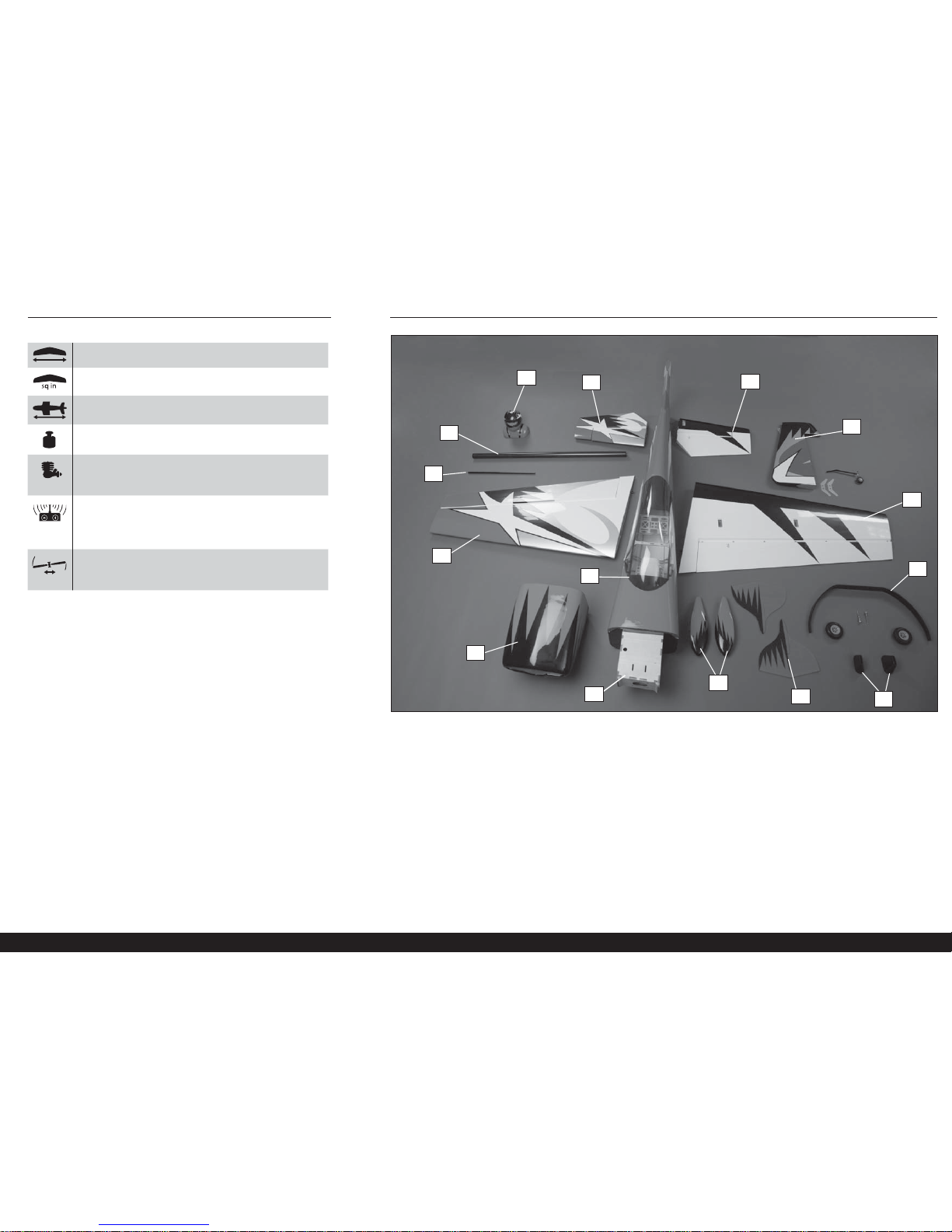
LARGE PARTS LAYOUT • BAUTEILE (OHNE KLEINTEILE) • GRANDES PIÈCES • SCHEMA DEI COMPONENTI GRANDI SPECIFICATIONS • SPEZIFIKATIONEN • SPÉCIFICATIONS • SPECIFICHE
105 in (2.65 m)
2003 sq in (129 dm2) Total/Totale
98 in (2.5 m)
27–31 lbs (12.2–14.1 kg)
2-Stroke Gas • 2-Takt Benziner
2 temps Essence • 2-Tempi Gas:
100cc–120cc
4-channel (or greater) with 8 servos
4-Kanal (oder größer) mit 8-Servos
4 voies (ou plus) avec 8 servos
a 4 canali (o più) con 8 servo
Spinner • Spinner • Cône • Ogiva dell’elica: 41/2-inch (114mm)
(not included • nicht im Lieferumfang enthalten •
non inclus • non inclusa)
1
3
2
4
5
6
7
8
9
10
12
13
14
15
11

3
Extra 300 X 120cc
Part # English Deutsch Français Italiano
REPLACEMENT PARTS • ERSATZTEILE • PIÈCES DE RECHANGE • PEZZI DI RICAMBIO
1 HAN922501 Fuselage with Hatch Rumpf mit Haube Fuselage avec capot Fusoliera con portello
2 HAN922502 Left Wing with Aileron Tragfl äche links m. Querruder Aile gauche avec aileron Semiala sinistra con alettone
3 HAN922503 Right Wing with Aileron Tragfl äche rechts m. Querruder Aile droite avec aileron Semiala destra con alettone
4 HAN922504 Left Stabilizer with Elevator Linkes Höhenleitwerk mit Höhenruder Stabilisateur gauche avec gouverne Stabilizzatore sinistro con elevatore
5 HAN922505 Right Stabilizer with Elevator Rechtes Höhenleitwerk mit Höhenruder Stabilisateur droit avec gouverne Stabilizzatore destro con elevatore
6 HAN922506 Rudder with Control Horn Ruder m. Horn Dérive avec guignol Timone con squadretta
7 HAN922507 Hatch with Canopy Öffnung mit Kabinenhaube Capot avec verrière Naca pilota
8 HAN922508 Cowling Motorhaube Capot moteur Carenatura
9 HAN922509 Landing Gear with Axles Fahrwerk m. Achsen Train d’atterrissage avec axes Carrello con assali
10 HAN922510 Carbon Wing Tube Flächenverbinder Clé d’aile en carbone Tubo ala in carbonio
11 HAN922511 Carbon Stabilizer Tube Carbon Leitwerksverbinder Clé de stabilisateur en carbone Tubo in carbonio per stabilizzatore
12 HAN922513 Pilot Pilot Pilote Pilota
13 HAN922514 Landing Gear Cuffs Landegestellmanschetten Carénages de train Cuffi e per carrello
14 HAN922518 Wheel Pant Set Radverkleidung Carénage de roue Copriruote
15 HAN922519 Side Force Generators Sideforce Generatoren Générateurs d’appui latéraux Generatori di spinta laterale
SMALL PARTS (NOT SHOWN) • KLEINTEILE (NICHT ABGEBILDET) • PETITES PIÈCES (NON REPRÉSENTÉES) • PARTI DI PICCOLE DIMENSIONI (NON MOSTRATE)
HAN922512 Decal Set Dekorbogen Planche de décoration Set di decalcomanie
HAN922515 Canister Mount Set Kanisterhalterungsset Set de fi xation de résonateur Set supporto serbatoio
HAN922516 Fiberglass Control Horn Set Ruderhornset, GFK Guignols en fi bre de verre Set squadrette in vetroresina
HAN922517 Hardware Set Kleinteile Set Sachet de visserie Set dei pezzi
HAN925 Assembled Fuel Tank: 32oz (950cc) Eingebauter Benzintank Réservoir à carburant assemblé Serbatoio del carburante assemblato
OPTIONAL ITEMS • OPTIONALE TEILE • ÉLÉMENTS OPTIONNELS • ARTICOLI OPZIONALI
SPM9548
TM1000 DSMX Full Range Aircraft Telemetry
Module
Spektrum DSM Telemetriemodul TM1000 Module de télémétrie TM1000 DSMX Modulo di telemetria per aereo a piena portata
EVOA100 Optical Kill Switch Optischer Killschalter Interrupteur coupe-circuit optique Interruttore ottico di spegnimento
WGT211
Extreme Big Tote Double 59 x 35 x 22 inch
Red & Black Wing Bag
Extreme Big Tote Double 59 x 35 x 22 inch Rot &
Schwarz Flächentasche
Sac de transport pour 2 ailes Extreme Big Tote 150 x
90 x 55 cm rouge/noir
Custodie Alari 150 X 90 X 55 cm Rosse e Nere

4
Part # English Deutsch Français Italiano
RECEIVER (RECOMMENDED) • EMPFÄNGER (EMPFOHLEN) • RÉCEPTEUR (RECOMMANDÉ) • RICEVENTE (CONSIGLIATO)
SPMAR9110
AR9110 9-Channel DSMX
®
PowerSafe™
Receiver
Spektrum AR9110 9-Kanal DSMX-PowerSafeEmpfänger
Récepteur DSMX PowerSafe 9 voies AR9110
Ricevente AR9110 9-canali DSMX®
PowerSafe™
SPMB4000LP (2) LiPo Receiver Pack 4000mAh Spektrum 4000mAh 2S 6,6V Li-Fe Empfängerakku Pack récepteur Li-Po 4000mA Batteria LiPo 4000mAh per ricevente
SPMB2000LP LiPo Receiver Pack 2000mAh Spektrum 2000mAh 2S 6,6V Li-Fe Empfängerakku Pack récepteur Li-Po 2000mA Batteria LiPo 2000mAh per ricevente
SPMEXEC324 (2)
24-Inch EC3 Extension with 16AWG
(Receiver to receiver batteries)
EC3-Verlängerung 600mm mit 16 AWG
(Empfänger zu Empfängerakkus)
Rallonge EC3 600 mm, section 1.5mm²
(Récepteur vers batterie récepteur)
Prolunga EC3 da 600 mm con 16 AWG
(Tra ricevente e batterie)
SPMA3043
Heavy-Duty Male to Male Extension 12-inch
(Data cable to receiver)
Spektrum 30,48 cm HochleistungsSteckerverlängerung
Rallonge renforcée mâle vers mâle longueur 304mm
(Câble données vers récepteur)
Prolunga alta capacità maschio-maschio da
30cm (Cavo dati alla ricevente)
RECEIVER (OPTION 1) • EMPFÄNGER (OPTION 1) • RÉCEPTEUR (OPTION 1) • RICEVENTE (OPZIONE 1)
SPMAR9350
AR9350 9-Channel AS3X
®
Receiver
Spektrum AR9350 9-Kanal AS3X-Empfänger Récepteur AR9350 9 voies AS3X Ricevente AR9350 9-canali AS3X
SPMB4000LP
(1 or 2)
LiPo Receiver Pack 4000mAh Spektrum 4000mAh 2S 7,4V Lipo Empfängerpack Pack récepteur Li-Po 4000mA Batteria LiPo 4000mAh per ricevente
EVOA112 (1 or 2) Evolution 3 Wire Ignition/Rx Switch Evolution Zündschalter Interrupteur Evolution 3 fi ls Allumage/RX
Evolution, interruttore a 3 fi li accensione/
ricevitore
SPMA3005 (1 or 2) Heavy-Duty Servo Extension 24-inch Servokabelverlängerung 600 mm Rallonge de servo, 600 mm Estensione servo 600 mm
RECEIVER (OPTION 2) • EMPFÄNGER (OPTION 2) • RÉCEPTEUR (OPTION 2) • RICEVENTE (OPZIONE 2)
SPMAR12120
AR12120 12-Channel DSMX
®
X-Plus
PowerSafe
™
Receiver
Spektrum AR12120 12-Kanal X-Plus-DSMXPowerSafe-Empfänger
Récepteur DSMX X-Plus PowerSafe AR12120 12-voies
Ricevente AR12120 12-canali DSMX X-plus
PowerSafe
SPMB4000LP LiPo Receiver Pack 4000mAh Spektrum 4000mAh 2S 7,4V Lipo Empfängerpack Pack récepteur Li-Po 4000mA Batteria LiPo 4000mAh per ricevente
SPMEXEC324 (2)
24-Inch EC3 Extension with 16AWG
(Receiver to receiver batteries)
EC3-Verlängerung 600mm mit 16 AWG
(Empfänger zu Empfängerakkus)
Rallonge EC3 600 mm, section 1.5mm²
(Récepteur vers batterie récepteur)
Prolunga EC3 da 600 mm con 16 AWG
(Ricevente alle batterie ricevente
SPMA3043
Heavy-Duty Male to Male Extension 12-inch
(Data cable to receiver)
Spektrum 300 mm Hochleistungs-Steckerverlängerung
Rallonge renforcée mâle vers mâle longueur 300mm
(Câble données vers récepteur)
Prolunga alta capacità maschio-maschio da
30cm (Cavo dati alla ricevente)
SPMAS1000 Alpha-6™ AS3X® Stability System Spektrum Alpha-6 AS3X Stabilisierungssystem Système Stabilité Spektrum AS3X Alpha-6 Alpha-6 Sistema stabilizzante AS3X
REQUIRED RADIO EQUIPMENT • ERFORDERLICHE RC AUSRÜSTUNG • ÉQUIPEMENT RADIO REQUIS • APPARECCHIATURE RADIO NECESSARIE
Servos •
Servocomandi (8)
We recommend servos for the control
surfaces (7) have a minimum torque rating of
400 oz/in
Wir empfehlen für die Ruder Servos mit einer
Mindestkraft von 400 oz/inch (2.824 Newton meter).
Nous vous recommandons d’utiliser des servos avec un
couple minimum de 28 kg/cm pour les gouvernes (7).
Raccomandiamo di usare servocomandi con una
potenza non inferiore ai 28 kg/cm.
HAN9160 (7) Aluminum Servo Arm, 2-inch (JR/SPM) Hangar 9 Aluminium Servo Arm, 2” (JR/SPM) Palonnier de servo en aluminium, long 50mm (JR,SPM) Squadretta servo in alluminio 5cm (JR/SPM)
SPMA3004 (6)
Heavy Duty Servo Extension 18-inch
(Outer aileron servos and recevier to ailerons)
Servokabelverlängerung 460 mm
(Äußere Querruderservo und Empfänger zu Servo)
Rallonge de servo, 460 mm
(Servos ailerons externes et récepteur aux ailerons)
Estensione servo 460 mm (Servo alettone
esterno e dalla ricevente agli alettoni)
SPMA3005 (2)
Heavy-Duty Servo Extension 24-inch
(Rudder and Throttle servo to receiver)
Servokabelverlängerung 600 mm
(Seitenruder und Gasservo zu Empfänger)
Rallonge de servo, 600 mm
(Servo dérive et gaz au récepteur)
Estensione servo 600 mm
(Dai servi motore e timone alla ricevente)
SPMA3006 (2)
Heavy-Duty Servo Extension 36-inch
(Elevator servos to receiver)
Servokabelverlängerung 920 mm
(Höhenruderservo zu Empfänger)
Rallonge de servo, 920 mm
(Servos profondeur au récepteur)
Estensione servo 920 mm
(Dai servi elevatore alla ricevente)
2-STROKE GAS • 2-TAKT BENZINER • 2 TEMPS ESSENCE • 2-TEMPI A BENZINA
EVOE125GX 125GX 125cc Twin-Cylinder Gas Engine 125GX 125cc Zweizylinder Motor Moteur 125GX essence 125cc à deux cylindres Motore Bicilindrico 125GX 125cc
27 x 11 Propeller 27 x 11 Propeller Hélice 27 x 11 27 x 11 Elica
HAN116 Fuel Filler with “T” and Overfl ow Fittings Tanknippel mit T-Stück u. Überlauf Fitting Point de remplissage de carburant avec coupleur en T Riempitore carburante con “T” e raccordi troppo
Compact muffl er for DA-120 Kompaktschalldämpfer für DA-120 Silencieux compact pour DA-120 Silenziatore compatto per DA-120
SPMB2000LP LiPo Receiver Pack 2000mAh Spektrum 2000mAh 2S 7,4V Lipo Empfängerpack Pack récepteur Li-Po 2000mA Batteria LiPo 2000mAh per ricevente
EVOA112 Evolution 3 Wire Ignition/Rx Switch Evolution Zündschalter Interrupteur Evolution 3 fi ls Allumage/RX
Evolution, interruttore a 3 fi li accensione/
ricevitore

5
Extra 300 X 120cc
Part # English Deutsch Français Italiano
TRU4552BM3WAB
4
1
/2-inch Ultimate Menz Cut 28" 2-Blade
Black Anodized
41/2-inch Ultimate Menz Cut 28” 2-Blade
Black Anodized
Cône 41/2-inch Ultimate Menz Cut 28” bipale noir
anodisé
41/2-inch Ultimate Menz Cut 28” 2-pale
Anodizzato nero
Part # English Deutsch Français Italiano
REQUIRED ADHESIVES • ERFORDERLICHE KLEBSTOFFE • TYPES DE COLLES • ADESIVI NECESSARI
PAAPT09 Thin CA Sekundenkleber dünnfl üssig Colle cyano fi ne Sottile CA
PAAPT03 Medium CA Sekundenkleber mittel Colle cyano moyenne Medio CA
PAAPT715 CA Accelerator Sekundenkleber (CA) Aktivator Accélérateur de colle CA Accelerante colla CA
PAAPT56 Canopy Glue Kanzelkleber Colle pour verrière Colla per capottine
PAAPT35 15-Minute Epoxy 15 Minuten Epoxy Époxy 15 minutes Colla epoxy 15 minuti
PAAPT39 30-Minute Epoxy 30 Minuten Epoxy Époxy 30 minutes Colla epoxy 30 minuti
PAAPT42 Threadlock Schraubensicherungslack Frein-fi let Frenafi letti
REQUIRED TOOLS • BENÖTIGTES WERKZEUG • OUTILS REQUIS • ATTREZZI NECESSARI
Box wrench: 10mm, 1/2-inch Ringschlüssel 10mm, 1/2-inch Clé hexagonale: 10mm, 1/2-inch Chiave esagonale: 10mm, 1/2-inch
Drill Bohrer Mini-perceuse Trapano
Drill bit: 1/16-inch, 5/64-inch,
17/64-inch
Bohrer: 1,5mm, 2mm, 7mm Forêt : 1,5mm, 2mm, 7mm Punte per trapano: 1,5mm, 2mm, 7mm
Felt-tipped pen Faserstift Feutre fi n effaçable Pennarello
Hemostats Klemme Pince Hemostat Pinzetta
Hex wrench: 3/32-inch, 3/16-inch, 7/64-inch,
2.5mm
Inbusschlüssel: 3/32-inch, 3/16-inch, 7/64-inch,
2,5mm
Tournevis hexagonal : 3/32-inch, 3/16-inch, 7/64-inch,
2,5mm
Chiave esag.: 3/32-inch, 3/16-inch, 7/64-inch,
2,5mm
Hobby knife with #11 blade Hobbymesser mit # 11 Klinge Couteau : Lame numéro 11 Taglierino: #11 lama
Isoplrpyl alcohol Isopropyl Alkohol Alcool isopropylique Alcol isopropilico
Low-tack tape Kreppband Adhésif de masquage Nastro a bassa aderenza
Needle nose pliers Spitzzange Pince fi ne Pinze a becco stretto
Nut driver: 1/4-inch, 11/32-inch Steckschlüssel. 1/4-inch, 11/32-inch Clés à douilles : 1/4-inch, 11/32 pouce Chiave per dadi: 1/4-inch, 11/32-inch
Paper towels Papiertücher Papier absorbant Asciugamani di carta
Pencil Stift Crayon à papier Matita
Phillips screwdriver: #1 Phillips Schraubendreher: #1 Tournevis cruciforme: #1 Cacciavite a croce: #1
Pin vise Handbohrer Porte forets Trapano manuale
Pliers Zange Pince Pinze
Ruler Lineal Réglet Righello
Sandpaper Schleifpapier Papier de verre Carta vetrata
Scissors Schere Ciseaux Forbici
Side cutters Seitenschneider Pince coupante Lama laterale
Square Geodreieck Équerre Squadra
Tap and drill set, English Gewindeschneider und Bohrerset Taraud et foret Set punte e maschi, Inglese
Tap Handle Halter für Gewindeschneider Épingles Impugnatura per maschiare

6
NOTICE
All instructions, warranties and other collateral documents are subject to change at the sole discretion of Horizon
Hobby, LLC. For up-to-date product literature, visit horizonhobby.com and click on the support tab for this product.
The following terms are used throughout the product literature to indicate various levels of potential harm when
operating this product:
Meaning of Special Language
NOTICE: Procedures, which if not properly followed, create a possibility of physical property damage AND a little or
no possibility of injury.
CAUTION: Procedures, which if not properly followed, create the probability of physical property damage AND a
possibility of serious injury.
WARNING: Procedures, which if not properly followed, create the probability of property damage, collateral damage,
and serious injury OR create a high probability of superfi cial injury.
WARNING: Read the ENTIRE instruction manual to become familiar with the features of the product before operating.
Failure to operate the product correctly can result in damage to the product, personal property and cause serious
injury.
This is a sophisticated hobby product. It must be operated with caution and common sense and requires some basic
mechanical ability. Failure to operate this Product in a safe and responsible manner could result in injury or damage
to the product or other property. This product is not intended for use by children without direct adult supervision. Do
not attempt disassembly, use with incompatible components or augment product in any way without the approval
of Horizon Hobby, LLC. This manual contains instructions for safety, operation and maintenance. It is essential to
read and follow all the instructions and warnings in the manual, prior to assembly, setup or use, in order to operate
correctly and avoid damage or serious injury.
AGE RECOMMENDATION: NOT FOR CHILDREN UNDER 14 YEARS. THIS IS NOT A TOY.
USING THE MANUAL
This manual is divided into sections to help make assembly easier to understand.
SAFETY WARNINGS AND PRECAUTIONS
Read and follow all instructions and safety precautions before use. Improper use can result in fi re, serious injury and
damage to property.
Components
Use only with compatible components. Should any compatibility questions exist, please refer to the product
instructions, component instructions or contact the appropriate Horizon Hobby offi ce.
Flight
Fly only in open areas to ensure safety. It is recommended fl ying be done at radio control fl ying fi elds. Consult local
ordinances before choosing a fl ying location.
Propeller
Keep loose items that can become entangled in the propeller away from the prop. This includes loose clothing or other
objects such as pencils and screwdrivers. Keep your hands away from the propeller as injury can occur.
Batteries
Always follow the manufacturer’s instructions when using and disposing of any batteries. Mishandling of Li-Po
batteries can result in fi re causing serious injury and damage.
Small Parts
This kit includes small parts and should not be left unattended near children as choking and serious injury could result.
SAFE OPERATING RECOMMENDATIONS
• Inspect your model before every fl ight to ensure it is airworthy.
• Be aware of any other radio frequency user who may present an interference problem.
• Always be courteous and respectful of other users in your selected fl ight area.
• Choose an area clear of obstacles and large enough to safely accomodate your fl ying activity.
• Make sure this area is clear of friends and spectators prior to launching your aircraft.
• Be aware of other activities in the vicinity of your fl ight path that could cause potential confl ict.
• Carefully plan your fl ight path prior to launch.
• Abide by any and all established AMA National Model Aircraft Safety Code.
BEFORE STARTING ASSEMBLY
• Remove parts from bag.
• Inspect fuselage, wing panels, rudder and stabilizer for damage.
• If you fi nd damaged or missing parts, contact your place of purchase.
If you fi nd any wrinkles in the covering, use a heat gun (HAN100) and covering glove (HAN150) or covering iron
(HAN101) with a sealing iron sock (HAN141) to remove them. Use caution while working around areas where the colors
overlap to prevent separating the colors.
• Charge transmitter and receiver batteries.
• Center trims and sticks on your transmitter.
• For a computer radio, create a model memory for this particular model.
• Bind your transmitter and receiver, using your radio system’s instructions.
IMPORTANT: Rebind the radio system once all control throws are set. This will keep the servos from moving to
their endpoints until the transmitter and receiver connect. It will also guarantee the servo reversal settings are
saved in the radio system.

7
Extra 300 X 120cc
Propeller
Halten Sie lose Gegenstände die sich im Propeller verfangen können weg vom Propeller. Dieses gilt auch für Kleidung
oder andere Objekte wie zum Beispiel Stifte oder Schraubendreher.
Halten Sie ihre Hände weg vom Propeller, es besteht akute Verletzungsgefahr.
Akkus
Folgen Sie immer den Herstelleranweisungen bei dem Gebrauch oder Entsorgung von Akkus. Falsche Behandlung von
LiPo Akkus kann zu Feuer mit Körperverletzungen und Sachbeschädigung führen.
Kleinteile
Dieser Baukasten beinhaltet Kleinteile und darf nicht unbeobachtet in der Nähe von Kindern gelassen werden, da die
Teile verschluckt werden könnten mit ernsthaften Verletzung zur Folge.
EMPFEHLUNGEN ZUM SICHEREN BETRIEB
• Überprüfen Sie zur Flugtauglichkeit ihr Modell vor jedem Flug.
• Beachten Sie andere Piloten deren Sendefrequenzen ihre Frequenz stören könnte.
• Begegnen Sie anderen Piloten in ihrem Fluggebiet immer höfl ich und respektvoll.
• Wählen Sie ein Fluggebiet, dass frei von Hindernissen und groß genug ist.
• Stellen Sie vor dem Start sicher, dass die Fläche frei von Freunden und Zuschauern ist.
• Beobachten Sie den Luftraum und andere Flugzeuge/Objekte die ihren Flugweg kreuzen und zu einem Konfl ikt
führen könnten.
• Planen Sie sorgfältig ihren Flugweg vor dem Start.
VOR DEM ZUSAMMENBAU
• Entnehmen Sie zur Überprüfung jedes Teil der Verpackung.
• Überprüfen Sie den Rumpf, Tragfl ächen, Seiten- und Höhenruder auf Beschädigung.
• Sollten Sie beschädigte oder fehlende Teile feststellen, kontaktieren Sie bitte den Verkäufer.
Zum Entfernen von Falten in der Bespannung verwenden Sie den Heißluftfön (HAN100) und Bespannhandschuh
(HAN150) oder das Folienbügeleisen (HAN141). Bitte achten Sie bei überlappenden Farben, dass Sie diese sich bei
dem Bearbeitung nicht trennen.
• Laden des Senders und Empfängers.
• Zentrieren der Trimmungen und Sticks auf dem Sender.
• Sollten Sie einen Computersender verwenden, resetten Sie einen Speicherplatz und benennen ihn nach dem Modell.
• Sender und Empfänger jetzt nach den Bindeanweisung des Herstellers zu binden.
WICHTIG: Wir empfehlen dringend nachdem alle Einstellungen vorgenommen worden sind, das Modell neu zu binden.
Dieses verhindert, dass die Servos in die Endanschläge laufen bevor sich Sender und Empfänger verbunden haben. Es
garantiert auch, dass die Servoreverseeinstellungen in der RC Anlage gesichert sind.
HINWEIS
Alle Anweisungen, Garantien und anderen zugehörigen Dokumente können im eigenen Ermessen von Horizon Hobby,
LLC. jederzeit geändert werden Die aktuelle Produktliteratur fi nden Sie auf horizonhobby.com unter der Registerkarte
„Support“ für das betreffende Produkt.
Spezielle Bedeutungen
Die folgenden Begriffe werden in der gesamten Produktliteratur verwendet, um auf unterschiedlich hohe
Gefahrenrisiken beim Betrieb dieses Produkts hinzuweisen:
HINWEIS: Wenn diese Verfahren nicht korrekt befolgt werden, können sich möglicherweise Sachschäden UND geringe
oder keine Gefahr von Verletzungen ergeben.
ACHTUNG: Wenn diese Verfahren nicht korrekt befolgt werden, ergeben sich wahrscheinlich Sachschäden UND die
Gefahr von schweren Verletzungen.
WARNUNG: Wenn diese Verfahren nicht korrekt befolgt werden, ergeben sich wahrscheinlich Sachschäden,
Kollateralschäden und schwere Verletzungen ODER mit hoher Wahrscheinlichkeit oberfl ächliche Verletzungen.
WARNUNG: Lesen Sie die GESAMTE Bedienungsanleitung, um sich vor dem Betrieb mit den Produktfunktionen
vertraut zu machen. Wird das Produkt nicht korrekt betrieben, kann dies zu Schäden am Produkt oder persönlichem
Eigentum führen oder schwere Verletzungen verursachen.
Dies ist ein hochentwickeltes Hobby-Produkt. Es muss mit Vorsicht und gesundem Menschenverstand betrieben
werden und benötigt gewisse mechanische Grundfähigkeiten. Wird dieses Produkt nicht auf eine sichere und
verantwortungsvolle Weise betrieben, kann dies zu Verletzungen oder Schäden am Produkt oder anderen Sachwerten
führen. Dieses Produkt eignet sich nicht für die Verwendung durch Kinder ohne direkte Überwachung eines
Erwachsenen. Verwenden Sie das Produkt nicht mit inkompatiblen Komponenten oder verändern es in jedweder Art
ausserhalb der von Horizon Hobby, LLC vorgegebenen Anweisungen. Diese Bedienungsanleitung enthält Anweisungen
für Sicherheit, Betrieb und Wartung. Es ist unbedingt notwendig, vor Zusammenbau, Einrichtung oder Verwendung
alle Anweisungen und Warnhinweise im Handbuch zu lesen und zu befolgen, damit es bestimmungsgemäß betrieben
werden kann und Schäden oder schwere Verletzungen vermieden werden.
NICHT GEEIGNET FÜR KINDER UNTER 14 JAHREN. DIES IST KEIN SPIELZEUG.
ÜBER DIESE ANLEITUNG
Diese Anleitung ist zur Vereinfachung des Zusammenbaues in Sektionen unterteilt.
WARNUNGEN UND SICHERHEITS-VORKEHRUNGEN
Bitte lesen und befolgen Sie alle Anweisungen und Sicherheitsvorkehrungen vor dem Gebrauch. Falscher, nicht
sachgemäßer Gebrauch kann Feuer, ernsthafte Verletzungen und Sachbeschädigungen zur Folge haben.
Komponenten
Verwenden Sie mit dem Produkt nur kompatible Komponenten. Sollten Fragen zur Kompatibilität auftreten, lesen Sie
bitte die Produkt- oder Bedienungsanweisung oder kontaktieren den Service von Horizon Hobby.
Fliegen
Fliegen Sie um Sicherheit garantieren zu können, nur in weiten offenen Gegenden. Wir empfehlen hier den Betrieb auf
zugelassenen Modellfl ugplätzen. Bitte beachten Sie lokale Vorschriften und Gesetze, bevor Sie einen Platz zum Fliegen
wählen.

8
L’hélice
Gardez éloignés tous les éléments qui pourraient être attrapés par l’hélice. Cela inclut les vêtements larges ou les
objets comme des outils par exemple. Gardez toujours vos mains à distance pour éviter tout cas de blessures.
Les batteries
Suivez toujours les instructions du fabricant de vos batteries. Une mauvaise manipulation d’une batterie Li-Po peut
entraîner un incendie causant de graves dégâts matériels et des blessures corporelles.
Petites pièces
Ce kit contient des petites pièces qui ne doivent pas être laissées à la portée des enfants, ces pièces sont dangereuses
pour eux et peuvent entraîner de graves blessures.
CONSIGNES DE SÉCURITÉ CONCERNANT L’UTILISATION
• Inspectez votre modèle avant chaque vol.
• Surveillez les fréquences utilisées à proximité.
• Soyez toujours courtois et respectueux des autres utilisateurs de la zone de vol.
• Choisissez une zone dégagée de tout obstacle et suffi samment grande pour voler en toute sécurité.
• Contrôlez que la zone est libre de spectateurs avant de lancer votre modèle.
• Soyez conscient des autres activités aux alentours de votre vol, risque de confl it potentiel.
• Planifi ez votre vol avant de le commencer.
AVANT DE COMMENCER L’ASSEMBLAGE
• Retirez toutes les pièces des sachets pour les inspecter.
• Inspectez soigneusement le fuselage, les ailes et les empennages.
• Si un élément est endommagé, contactez votre revendeur.
Si l’entoilage présente quelque plis, vous pouvez les lisser en utilisant le pistolet à air chaud (HAN100) et le gant
(HAN150) ou le fer à entoiler (HAN101) avec la chaussette de protection (HAN141). Agissez soigneusement dans les
zones où plusieurs couleurs d’entoilage sont superposées afi n d’éviter de les séparer.
• ll est recommandé de préparer tous les éléments du système de la radio.
• Cela inclut la charge des batteries comme la mise au neutre des trims et des manches de votre émetteur.
• Si vous utilisez une radio programmable, sélectionnez une mémoire libre afi n d’y enregistrer les paramètres de ce
modèle.
• Nous vous recommandons d’affecter maintenant le récepteur à l’émetteur en suivant les instructions fournies avec
votre radio.
IMPORTANT: Il est hautement recommandé de ré-affecter le système une fois que les courses seront réglées. Cela
empêchera les servos d’aller en butée lors de la connexion du système. Cela garantit également que la direction des
servos est enregistrée dans l’émetteur.
REMARQUE
La totalité des instructions, garanties et autres documents est sujette à modifi cation à la seule discrétion d’Horizon
Hobby, LLC. Pour obtenir la documentation àjour, rendez-vous sur le site horizonhobby.com et cliquez sur l’onglet de
support de ce produit.
Signifi cation de certains termes spécifi ques
Les termes suivants sont utilisés dans l’ensemble du manuel pour indiquer différents niveaux de danger lors de
l’utilisation de ce produit:
REMARQUE: Procédures qui, si elles ne sont pas suivies correctement, peuvent entraîner des dégâts matériels ET
éventuellement un faible risque de blessures.
ATTENTION: Procédures qui, si elles ne sont pas suivies correctement, peuvent entraîner des dégâts matériels ET des
blessures graves.
AVERTISSEMENT: Procédures qui, si elles ne sont pas suivies correctement, peuvent entraîner des dégâts matériels
et des blessures graves OU engendrer une probabilité élevée de blessure superfi cielle.
AVERTISSEMENT: Lisez la TOTALITÉ du manuel d’utilisation afi n de vous familiariser avec les caractéristiques du
produit avant de le faire fonctionner. Une utilisation incorrecte du produit peut entraîner sa détérioration, ainsi que des
risques de dégâts matériels, voire de blessures graves.
Ceci est un produit de loisirs sophistiqué. Il doit être manipulé avec prudence et bon sens et requiert des aptitudes
de base en mécanique. Toute utilisation irresponsable de ce produit ne respectant pas les principes de sécurité peut
provoquer des blessures, entraîner des dégâts matériels et endommager le produit. Ce produit n’est pas destiné à
être utilisé par des enfants sans la surveillance directe d’un adulte. N’essayez pas de modifi er ou d’utiliser ce produit
avec des composants incompatibles hors des instructions fournies par Horizon Hobby, LLC. Ce manuel comporte des
instructions relatives à la sécurité, au fonctionnement et à l’entretien. Il est capital de lire et de respecter la totalité
des instructions et avertissements du manuel avant l’assemblage, le réglage et l’utilisation, ceci afi n de manipuler
correctement l’appareil et d’éviter tout dégât matériel ou toute blessure grave.
14 ANS ET PLUS. CECI N’EST PAS UN JOUET.
UTILISATION DU MANUEL
Ce manuel est divisé en sections pour vous aider à comprendre plus facilement l’assemblage.
AVERTISSEMENTS RELATIFS À LA SÉCURITÉ
Lisez et suivez toutes les instructions relatives à la sécurité avant utilisation. Une utilisation inappropriée peut entraîner
un incendie, de graves blessures et des dégâts matériels.
Composants
Utilisez uniquement des composants compatibles. Si vous avez des questions concernant la compatibilité, référez-vous
à ce manuel ou contactez le service technique Horizon Hobby.
Le vol
Volez uniquement dans des zones dégagées pour un maximum de sécurité. Il est recommandé d’utiliser les pistes des
clubs d’aéromodélisme. Consultez votre mairie pour connaître les sites autorisés.

9
Extra 300 X 120cc
AVVISO
Tutte le istruzioni, le garanzie e gli altri documenti pertinenti sono soggetti a cambiamenti a totale discrezione di
Horizon Hobby, LLC. Per una documentazione aggiornata sul prodotto, visitare il sito www.horizonhobby.com e fare
clic sulla sezione Support per questo prodotto.
Signifi cato dei termini particolari
In tutta la documentazione relativa al prodotto sono utilizzati iseguenti termini per indicare vari livelli di potenziale
pericolo durante il funzionamento:
AVVISO: Procedure che, se non sono seguite correttamente, possono creare danni materiali E nessuna oscarsa
possibilità di lesioni.
ATTENZIONE: Procedure che, se non sono seguite correttamente, possono creare danni materiali E possibili gravi
lesioni.
AVVERTENZA: Procedure che, se non debitamente seguite, espongono alla possibilità di danni alla proprietà fi sica
opossono omportare un’elevata possibilità di provocare ferite superfi ciali. Ulteriori precauzioni per la sicurezza e
avvertenze.
AVVERTENZA: Leggere TUTTO il manuale di istruzioni e prendere familiarità con le caratteristiche del prodotto, prima
di farlo funzionare. Un utilizzo scorretto del prodotto può causare danni al prodotto stesso, alle persone oalle cose,
provocando gravi lesioni.
Questo è un prodotto di hobbistica sofi sticato e NON un giocattolo. È necessario farlo funzionare con cautela e
responsabilità e avere conoscenze basilari di meccanica. Se questo prodotto non è utilizzato in maniera sicura e
responsabile potrebbero verifi carsi lesioni odanni al prodotto stesso oad altre proprietà. Non è un prodotto adatto
aessere utilizzato dai bambini senza la diretta supervisione di un adulto. Non usare componenti non compatibili
o alterare il prodotto in nessuna maniera al di fuori delle istruzioni fornite da Horizon Hobby, LLC. Questo manuale
contiene le istruzioni per un funzionamento e una manutenzione sicuri. È fondamentale leggere e seguire tutte le
istruzioni e le avvertenze del manuale prima di montare, confi gurare ofar funzionare il Prodotto, al fi ne di utilizzarlo
correttamente e di evitare danni olesioni gravi.
ALMENO 14 ANNI. NON È UN GIOCATTOLO.
COME USARE IL MANUALE
Questo manuale è diviso in sezioni per rendere più facile la comprensione del montaggio.
AVVERTIMENTI E PRECAUZIONI PER LA SICUREZZA
Prima dell’uso leggere attentamente tutte le istruzioni e le precauzioni per la sicurezza. In caso contrario si potrebbero
procurare incendi, danni o ferite.
Componenti
Usare solo componenti compatibili. Se ci fossero dubbi riguardo alla compatibilità, è opportuno far riferimento alle
istruzioni relative al prodotto o ai componenti oppure rivolgersi al reparto Horizon Hobby di competenza.
Volo
Per sicurezza volare solo in aree molto ampie. Meglio se in campi volo autorizzati per modellismo. Consultare le
ordinanze locali prima di scegliere luogo dove volare.
Elica
Tenere gli oggetti liberi (vestiti, penne, cacciaviti, ecc.) lontano dall’elica, prima che vi restino impigliati. Bisogna fare
attenzione anche con le mani perché c’è il rischio di ferirsi anche gravemente.
Batterie
Quando si maneggiano o si utilizzano le batterie, bisogna attenersi alle istruzioni del costruttore; il rischio è di procurare
incendi, specialmente con le batterie LiPo, con danni e ferite serie.
Piccole parti
Questo kit comprende delle parti di piccole dimensioni e non lo si può lasciare incustodito se c’è la presenza di bambini
che li possono inghiottire e rimanere soffocati o intossicati.
RACCOMANDAZIONI PER OPERARE IN SICUREZZA
• Controllare attentamente il modello prima di ogni volo per accertarsi che sia idoneo.
• Essere consapevoli che un altro utente della frequenza in uso, potrebbe procurare delle interferenze.
• Essere sempre cortesi e rispettosi nei confronti degli altri utilizzatori dell’area in cui ci si trova.
• Scegliere un’area libera da ostacoli e abbastanza ampia da permettere lo svolgimento del volo in sicurezza.
• Prima del volo verifi care che l’area sia libera da amici e spettatori.
• Stare attenti alle altre attività che si svolgono in vicinanza della vostra traiettoria di volo, per evitare possibili confl itti.
• Pianifi care attentamente il volo prima di lanciare il modello.
• Rispettare sempre scrupolosamente le regole stabilite dall’associazione locale.
PRIMA DI INIZIARE IL MONTAGGIO
• Togliere tutti i pezzi dalla scatola.
• Verifi care che la fusoliera, l’ala e i piani di coda non siano danneggiati.
• Se si trovano parti danneggiate, contattare il negozio da cui è stato acquistato.
Se si trovano delle pieghe nella ricopertura, si possono togliere usando una pistola ad aria calda (HAN100) e guanto per
ricopertura (HAN150), oppure un ferro per ricopertura (HAN101) con la sua calza di protezione (HAN141). Usare cautela
quando si lavora in aree del rivestimento dove ci sono dei colori sovrapposti, per evitare la loro separazione.
• Caricare il trasmettitore e la batteria di volo.
• Centrare stick e trim sul trasmettitore.
• Con una radio computerizzata creare una nuova memoria per questo modello.
• Facendo riferimento alle istruzioni del radiocomando, connettere (bind) trasmettitore e ricevitore.
IMPORTANTE: Ripetere la procedura di connessione una volta regolate le corse, per evitare che i servi vadano a fi ne
corsa. Garantirà anche che le impostazioni di inversione del servo vengano salvate nel sistema radio.

10
BUILDING PRECAUTIONS
The wings of your model are constructed using a balsa
sheeted foam core to aid in reducing the weight of your
model yet maintain a strong structure. During assembly,
we recommend resting the parts on a soft surface such
as a soft towel to help prevent denting the sheeting.
REMOVING WRINKLES
The covering of your model may develop wrinkles during
shipping and will require the use of a heat gun (HAN100)
and covering glove (HAN150) or covering iron (HAN101)
with a sealing iron sock (HAN141) to remove them. Use
caution while working around areas where the colors
overlap to prevent separating the colors. Avoid using
too much heat, which could separate the colors. Placing
a cool damp cloth on adjacent colors will also help in
preventing the separation of the colors while removing
wrinkles.
TRANSPORTATION AND STORAGE
When transporting and storing your model, you will
need a minimum of 104 inches (2.6m) in length, and
29 inches (76cm) in height to accommodate the size
of the fuselage. We also recommend the use of a wing
bag (WGT211) and stabilizer bags to help protect these
surfaces during transport and storage. The control horns
and linkages can also cause damage to nearby surfaces
even when placed in storage bags. Always place surfaces
so the tops are together to prevent damage from the
control horns and linkages.
CANISTER MUFFLER OPTION
For canister muffl er installation two headers with
50mm drop and two 62cc Canister Muffl ers (EVOM12)
are required. Couplers and clamps will also be needed
to connect the canister muffl ers to the headers. The
required plywood parts to support the canister muffl ers
inside the fuselage have been included with your model.
HINWEISE ZUM BAU
Die Tragfl ächen des Modells bestehen aus einem
Balsaholz beplankten Styroporkern. Dieses sorgt für
niedriges Gewicht bei hoher Festigkeit. Wir empfehlen
diese Komponenten bei dem Bau auf eine weiche
Unterlage wie ein Handtuch zu legen um Druckstellen zu
vermeiden.
ENTFERNEN VON FALTEN
Während des Transportes können bei der Bespannung
Falten aufgetreten sein. Sie können diese mit dem
Heißluftfön (HAN100) und Bespannhandschuh (HAN150)
oder dem Bügeleisenbezug (HAN141) entfernen. Bitte
achten Sie bei überlappenden Farben diese nicht durch
zuviel Hitze zu lösen. Ein kühlendes Stück Stoff kann hier
neben den Falten aufgelegt helfen, dass die Farben sich
nicht trennen.
TRANSPORT UND LAGERUNG
Bei dem Transport des Modells benötigen Sie mindestens
2.6 Meter Länge und 76cm Höhe für den Rumpf. Wir
empfehlen ebenfalls Flächen- und Leitwerkstaschen um
Transportschäden zu vermeiden. Durch die Ruderhörner
können ebenfalls Flächen beschädigt werden, so dass
diese nur mit den Oberseiten zueinander gelagert werden
sollten.
KANISTER SCHALLDÄMPFEROPTION
Für den Einbau der Kanisterschalldämpfer sind zwei
50mm Krümmer und zwei 62CC Kanister Schalldämpfer
erforderlich. Zur Montage sind ebenfalls Verbinder und
Klemmen erforderlich. Die erforderlichen Sperrholzteile
zum Einbau der Schalldämpfer sind im Lieferumfang des
Models enthalten.
PRÉCAUTIONS D’ASSEMBLAGE
Les ailes de votre modèle sont fabriquées en mousse
recouverte de balsa moulé pour réduire la masse de votre
modèle tout en restant résistant. Lors de la construction
de votre modèle, nous vous recommandons de poser les
pièces sur une surface douce comme une serviette douce
pour éviter d’abîmer l’aile.
ÉLIMINATION DES PLIS
L’entoilage de votre modèle peut développer des plis
lors de l’expédition. Vous pouvez les lisser en utilisant le
pistolet à air chaud (HAN100) et le gant (HAN150) ou le
fer à entoiler (HAN101) avec la chaussette de protection
(HAN141). Soyez vigilant sur les zones où plusieurs
couleurs d’entoilage sont superposées, une température
trop élevée pourrait séparer les couleurs. Placez un
chiffon humide et froid sur les couleurs adjacentes pour
éviter leur séparation lorsque vous enlevez les plis.
TRANSPORT ET STOCKAGE
Lorsque vous transportez ou stockez votre modèle, il
vous faudra un espace d’au moins 2,6m de longueur et
76cm de hauteur pour accueillir le fuselage. Nous vous
recommandons également l’utilisation d’un sac pour ailes
(WGT211) et de sacs pour stabilisateurs pour les protéger
lors du transport ou stockage. Les guignols et tringleries
peuvent également endommager les gouvernes même
dans les sacs de stockage. Placez toujours les gouvernes
de façon à ce que les parties supérieures soient l’une
contre l’autre pour éviter les contacts et dommages
causés par les guignols ou tringleries.
RÉSONATEUR EN OPTION
Pour installer les résonateurs, vous aurez besoin de
deux coudes (déport 50mm) et deux résonateurs 62cc
(EVOM12). Vous aurez également besoin de durites
silicone et de colliers auto-serrants pour raccorder les
résonateurs aux coudes. Les supports de résonateur en
bois sont inclus dans le fuselage de votre modèle.
PRECAUZIONI PER LA COSTRUZIONE
L’ala di questo modello è costruita in polistirolo
rivestito con fogli di balsa per avere un peso ridotto
pur mantenendo una struttura robusta. Durante
l’assemblaggio, noi consigliamo di appoggiare le varie
parti su di una superfi cie morbida, tipo una salvietta, per
evitare ammaccature.
TOGLIERE LE GRINZE
rivestimento di questo modello potrebbe sviluppare delle
grinze durante la spedizione e quindi per toglierle, sarà
necessario usare una pistola termica (phon) (HAN100) e
un guanto speciale (HAN150), oppure un ferro apposito
per rivestimenti (HAN101) con la sua calza (HAN141).
Bisogna usare cautela quando si lavora intorno ad
aeree con sovrapposizione di colori per evitare la loro
separazione. Evitare di scaldare troppo per non separare
i colori. Mettere un panno umido fresco sui colori vicini,
aiuta a prevenire la separazione dei colori mentre si
tolgono le grinze.
TRASPORTO E DEPOSITO
Quando si trasporta o si tiene in magazzino questo
modello, sarà necessario uno spazio di 2,6 metri di
lunghezza e di 76 centimetri in altezza per adattarsi
alle dimensioni della fusoliera. Si consiglia anche di
usare una custodia per proteggere le ali (WGT211) e
lo stabilizzatore. Le squadrette e i rinvii possono pure
causare danni alle superfi ci vicine anche se sono
sistemate dentro alle custodie. Per evitare questo,
sistemare le superfi ci in modo da mettere a contatto le
loro parti superiori che non hanno squadrette o rinvii.
MARMITTA CANISTER OPZIONALE
Per l’installazione delle Marmite Canister sono necessari
due collettori da 50mm e due Marmitte Canister da 62cc
(EVOM12). I raccordi ed il materiale di fi ssaggio sono
necessari per connettere le Marmitte Canister ai collettori
( non forniti ). Le parti in legno necessarie a supportare
internamente le Marmitte Canister sono incluse.
11 EN
Extra 300 X 120cc
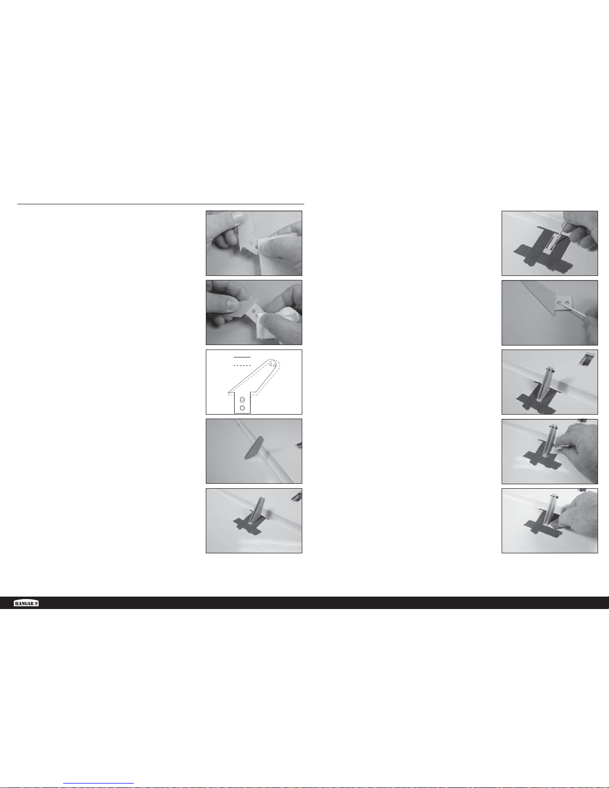
1. Sand the lower portion of the control horn where it fi ts
into the aileron using medium grit sandpaper.
6. Remove the control horns from the aileron. Apply a small
amount of 30-minute epoxy into each of the slots in the
aileron.
1.
2.
3.
A
B
4.
5.
2. Clean the oils and debris from the sanded area using a
paper towel and isopropyl alcohol.
7. Apply a small amount of 30-minute epoxy to the base of
the control horn using a toothpick.
3. Separate the control horns into two groups. The longer
horns are used toward the wing tip (A), and the shorter
horns toward the wing root (B).
8. Insert the control horns back into the aileron. Slide a 4-40
x 3/8-inch socket head cap screw through the hole in
the control horn to make sure they are aligned with each
other.
4. Fit the shorter control horns into the slots in the aileron
near the wing root. Insert them so they are fl ush with the
surface of the aileron. Check that they do not protrude
from the top of the aileron. Sand the base of the control
horn if it does protrude and deform the top of the aileron.
9. Remove any excess epoxy using a paper towel and
isopropyl alcohol.
5. Place low-tack tape on the aileron around the control
horns. This will keep the glue from getting on the aileron.
Removing the tape before the glue cures will leave a fi llet
between the control horn and aileron for a fi nished look.
10. Remove the tape while the epoxy is still slightly pliable.
This will allow the epoxy to fl ow between the control horn
and aileron creating a small fi llet. Remove the screw from
the control horn after the epoxy has fully cured.
11. Repeat the previous steps to install the control horns
toward the wing tip.
12. Repeat this section to install the control horns in the
opposite aileron.
AILERON CONTROL HORN INSTALLATION
6.
7.
8.
9.
10.
12EN
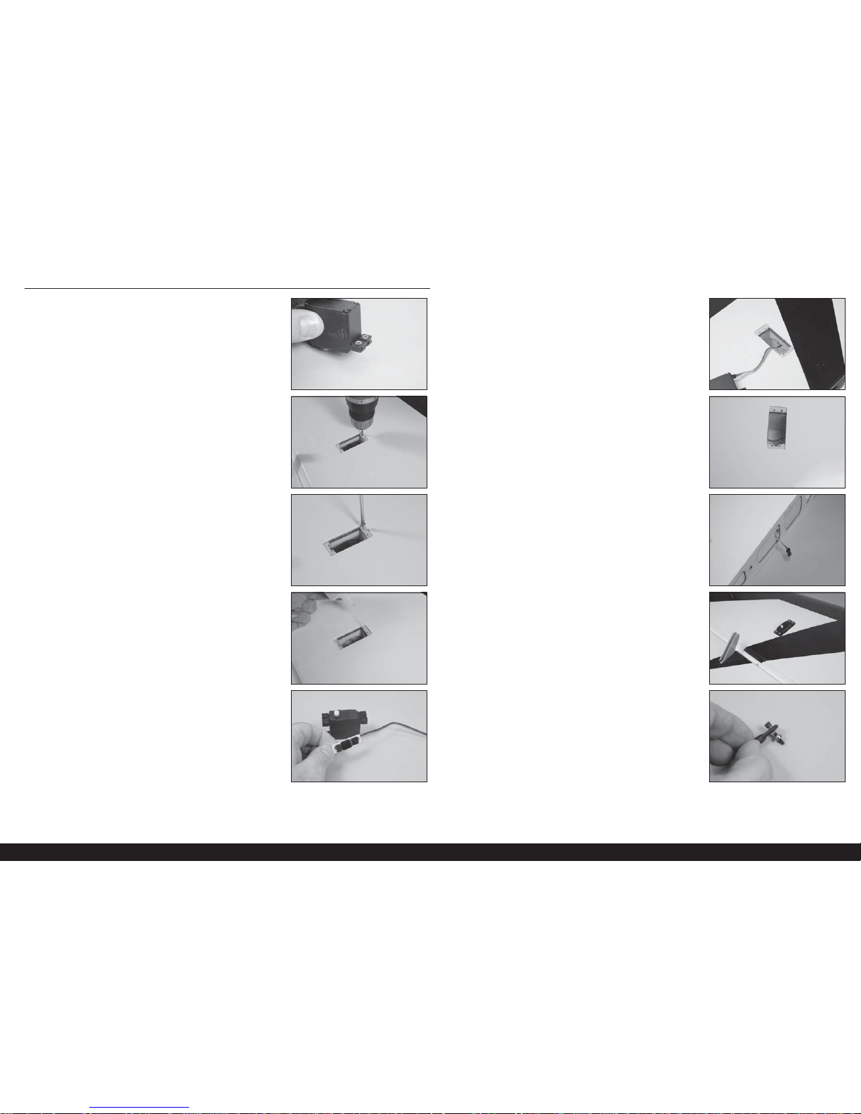
1. Install the grommets and brass eyelets in the servos.
Follow any instructions included with the servo. Prepare
both the root and tip aileron servos.
2. Enlarge the holes for the servo mounting screws using a
drill and 5/64-inch (2mm) drill bit. Prepare both the root
and tip servo openings at this time.
3. Thread a servo mounting screw into each of the mounting
holes to cut threads into the surrounding wood. Remove
the screws before proceeding. Prepare both root and tip
servo openings at this time.
4. Place 2 to 3 drops of thin CA into each hole to harden
the surrounding wood. Allow the CA to fully cure before
proceeding. Prepare both root and tip servo openings at
this time.
5. Secure an 18-inch (460mm) servo extension to the tip
servo using a commercially available fastener.
1.
2.
3.
4.
5.
AILERON SERVO INSTALLATION
6. Insert the servo extension into the hole in the wing at the
location for the tip servo.
7. Guide the servo lead through the area for the root aileron
servo.
8. Retrieve the servo lead at the wing root.
9. Place the tip servo in the wing with the output facing
toward the aileron. Secure the tip servo in the wing using
the screws included with the servo.
10. Insert a 4-40 x 5/8-inch socket head cap screw into the
metal ball of the ball link. Slide the conical washer on the
screw with the narrow end against the metal ball.
6.
7.
8.
9.
10.
13 EN
Extra 300 X 120cc
11. Thread the socket head cap screw into the hole of the
arm that is 1
3
/4 inches (44mm) from the center of the
servo arm.
16. Adjust the linkage to center the aileron while keeping
the servo centered with the radio system. Use a Pro-Link
Wrench (HAN3558) to make the adjustment process
easier.
17. Repeat steps 6 through 16 to install the root aileron servo.
Do not use a servo extension for the root aileron servo.
18. Repeat the previous section to install the aileron servos in
the opposite wing panel.
12. Secure the ball link to the servo arm using a 4-40 lock
nut. Use a 3/32-inch hex wrench and 1/4-inch nut driver
to tighten the hardware.
13. Center the tip aileron servo using the radio system.
Attach the servo arm parallel to the hinge line. Make any
adjustments to the alignment of the servo arm using the
sub-trim features of your radio system.
14. Thread the 3-inch (76mm) aileron linkage 10 turns into
the ball link on the servo arm. Thread a second ball link
10 turns on the opposite end of the turnbuckle.
15. Attach the second ball link to the tip aileron control horn
using a 4-40 x 5/8-inch socket head cap screw and a
4-40 lock nut. Use a 3/32-inch hex wrench and 1/4-inch
nut driver to tighten the hardware.
11.
12.
13.
14.
15.
16.
The elevator servo installation follows the same techniques as the aileron servos. This section has been
condensed, and any information that is not covered can be found in the previous sections regarding the
installation for the aileron servos.
1. Prepare and glue the control horns into position in the
elevator.
2. Prepare the stabilizer for the mounting of the elevator
servo. Mount the elevator servo in the stabilizer with the
output shaft facing toward the elevator. Make sure to
route the servo lead along the side of the elevator servo
when installing it into the opening.
3. Attach the ball link to the servo arm 2 inches (52mm)
from the center of the servo arm. Make sure to install the
conical washer between the ball link and servo arm. Use
a 4-40 x 5/8 socket head cap screw and 4-40 locknut as
the hardware for this step. Use a 3/32-inch hex wrench
and 1/4-inch nut driver to tighten the hardware.
1.
2.
3.
ELEVATOR SERVO INSTALLATION
14EN
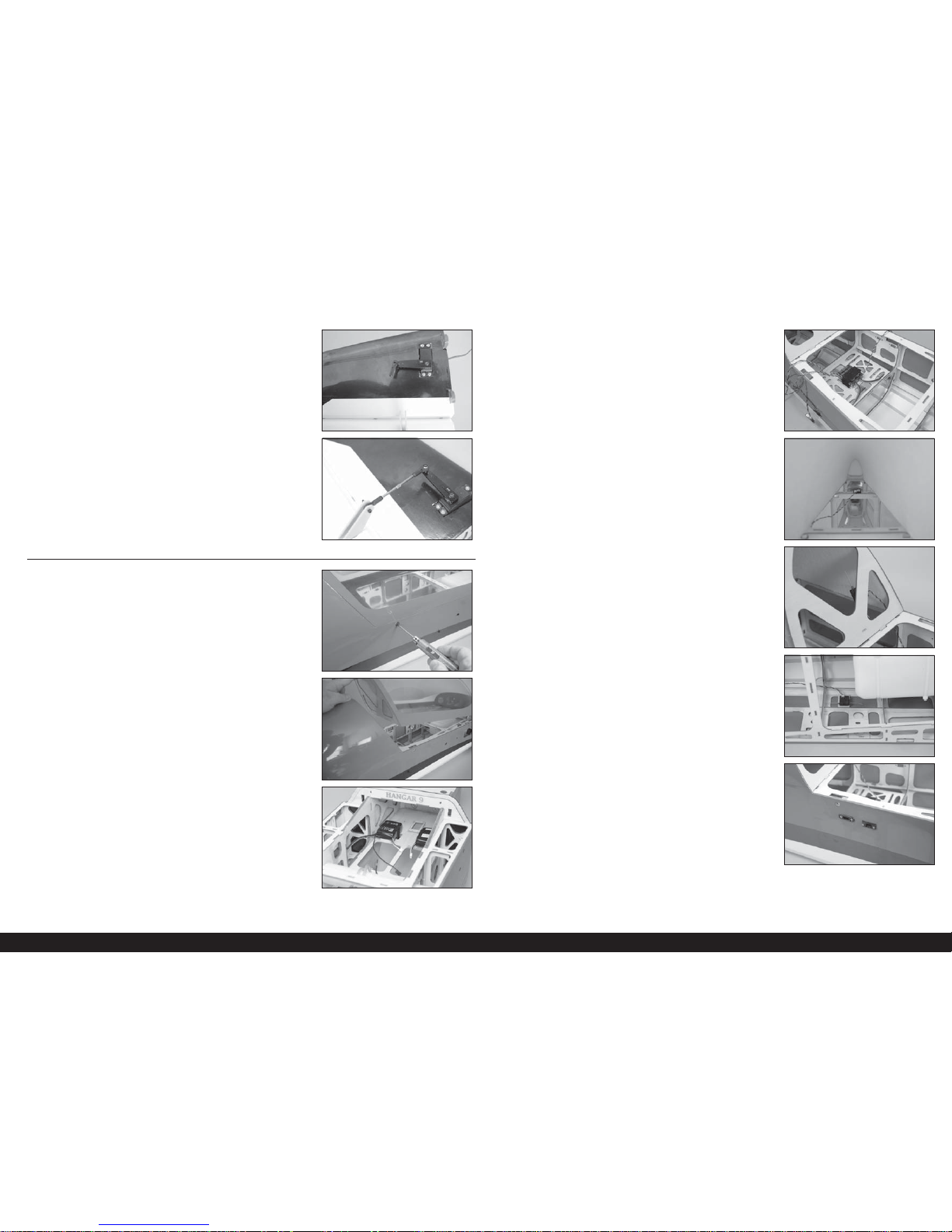
6. Mount the second remote receiver behind the opening
for the canopy. Face the antenna up and down for this
receiver.
4.
5.
6.
7.
8.
7. Mount the fi nal remote receiver in the fuselage where
the antenna can face forward and aft. Make a small plate
from plywood if necessary to mount the receiver to.
8. Mount the receiver switch and data jack to the side of the
fuselage. Use a hobby knife equipped with a #11 blade to
remove the covering and trim the openings as necessary.
Connect the switch and a data cable (not included) to the
receiver inside the fuselage.
4. Center the elevator servo using the radio system. Attach
the servo arm to the servo parallel to the elevator hinge
line. Adjust the servo if necessary using the sub-trim
feature of the radio system.
5. Install the 3-inch (76mm) linkage and remaining ball
link using a 4-40 x 5/8-inch socket head cap screw and
4-40 locknut. Adjust the length of the linkage to center
the elevator while the servo is centered using the radio
system. Use a 3/32-inch hex wrench and 1/4-inch nut
driver to tighten the hardware.
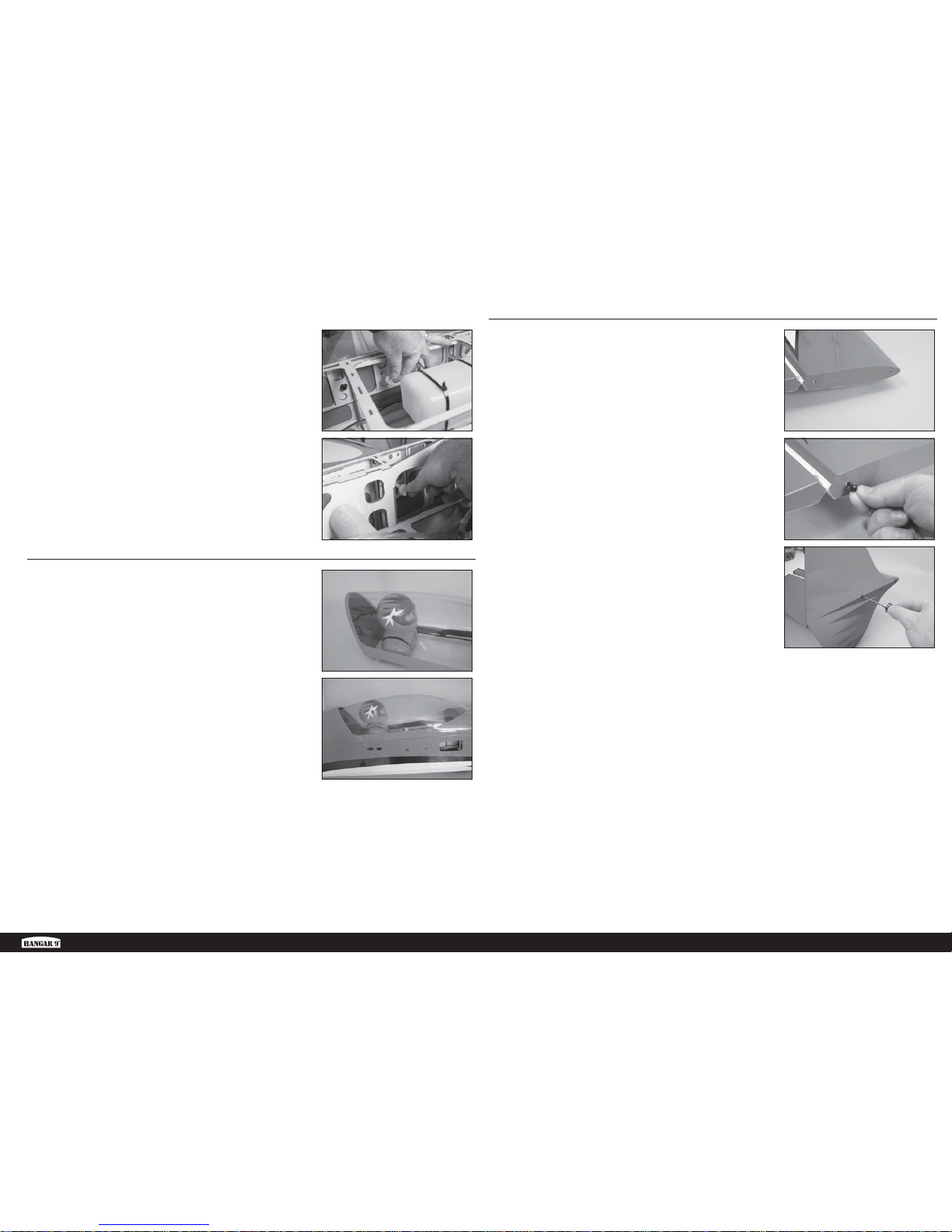
1. Remove the four screws holding the canopy hatch to the
fuselage using a 3/32-inch hex wrench.
2. Remove the canopy hatch from the fuselage by lifting it at
the rear. Slide the canopy hatch back and set it aside.
3. Cut one of the hook and loop straps into two equal pieces
using scissors. Secure the two receiver battery packs
in the fuselage. Place foam between the plywood and
batteries to help isolate them from vibrations.
4. Cut the remaining the hook and loop strap into two equal
pieces using scissors. Secure the receiver in the fuselage.
Place foam between the plywood and receiver to help
isolate it from vibrations.
5. Mount the remote receivers in the fuselage using hook
and loop tape (not included). Mount the fi rst remote
receiver as far back in the fuselage as possible with the
antenna facing toward the wing tips.
1.
2.
3.
RECEIVER AND BATTERY INSTALLATION
4.
5.
15 EN
Extra 300 X 120cc
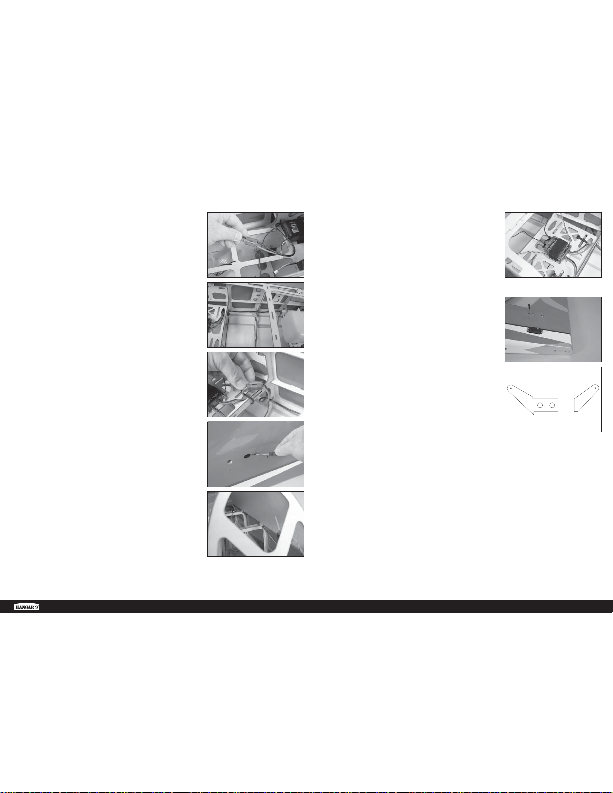
11. Connect the extension to the receiver power leads,
securing them with tie wraps.
12. Route the two 36-inch (920mm) servo extensions through
the opening in the side of the fuselage at the rear. Clip
the extension into the notch to hold it in position until the
elevators are installed, and when transporting the model
with the elevators off.
13. Route the extensions forward inside the fuselage.
Notches are located in the formers to route the extensions
through, keeping them from getting tangled inside the
fuselage.
14. Connect the 36-inch (920mm) servo extensions to the
receiver for the elevator servos.
9.
10.
11.
12.
13.
9. Secure the 24-inch (600mm) EC3 extensions to the
batteries using tie wraps.
10. Route the extensions through the fuselage, securing them
to the formers using tie wraps.
14.
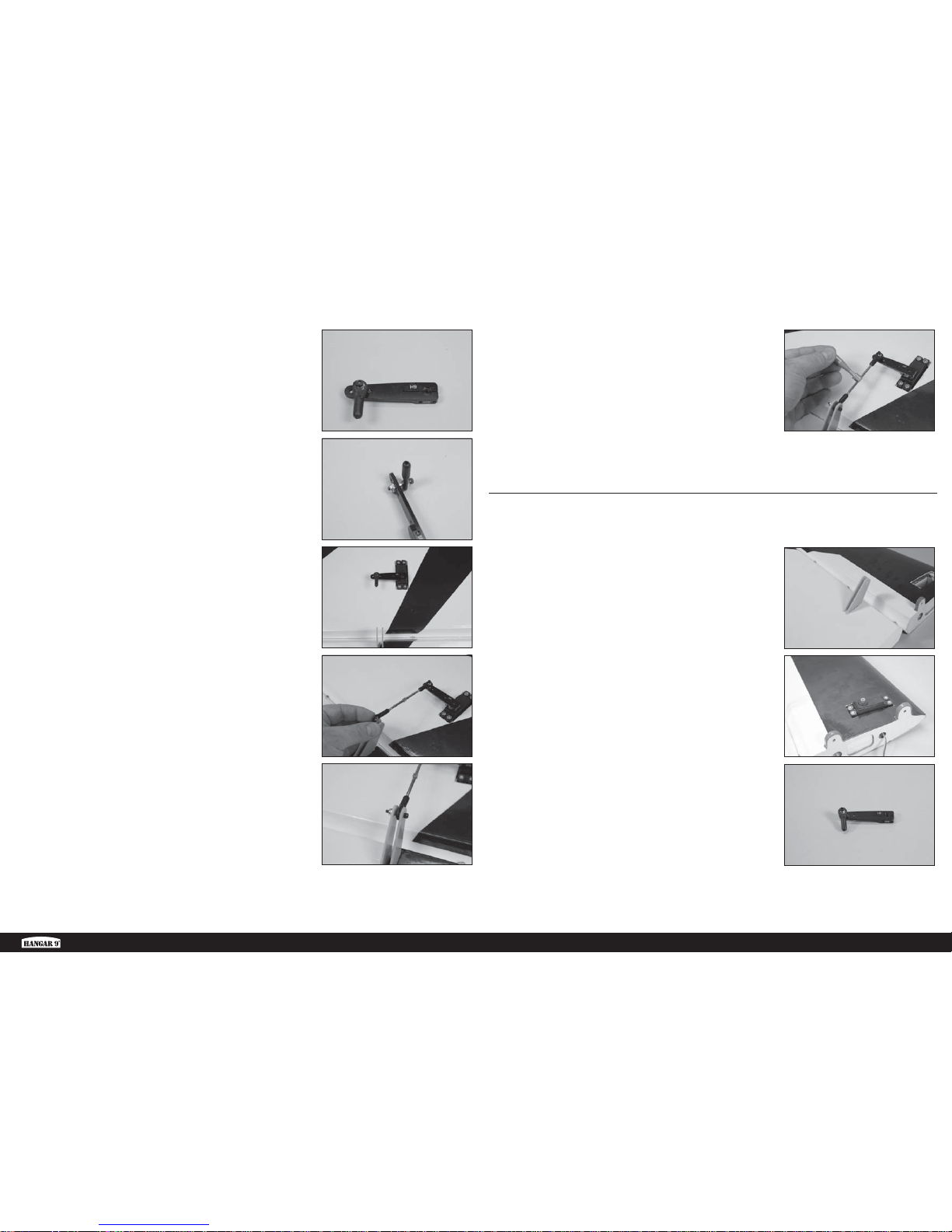
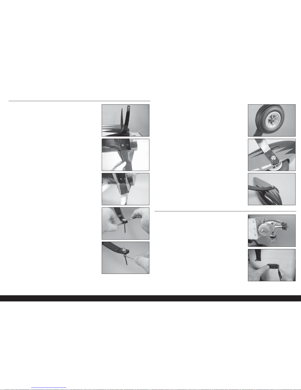
1. Prepare the rudder servo for installation by installing the
grommets and brass eyelets. Secure a 24-inch (600mm)
extension to the servo lead using a commercially
available fastener. Route the extension through the
fuselage and connect it to the rudder channel of the
receiver. Mount the servo in the fuselage with the output
facing toward the rear of the fuselage. Use the techniques
found earlier in this manual.
2. Prepare the rudder control horns for installation in the
rudder. The horns are designed to be used with dual
rudder servos. If you use a single rudder servo, the
control horn can be cut as shown.
Î We will be installing the rudder control horns
in the dual rudder configuration. Use the technique
as outlined earlier for the aileron control horns
to install the single rudder control horn.
1.
2.
RUDDER INSTALLATION
16EN
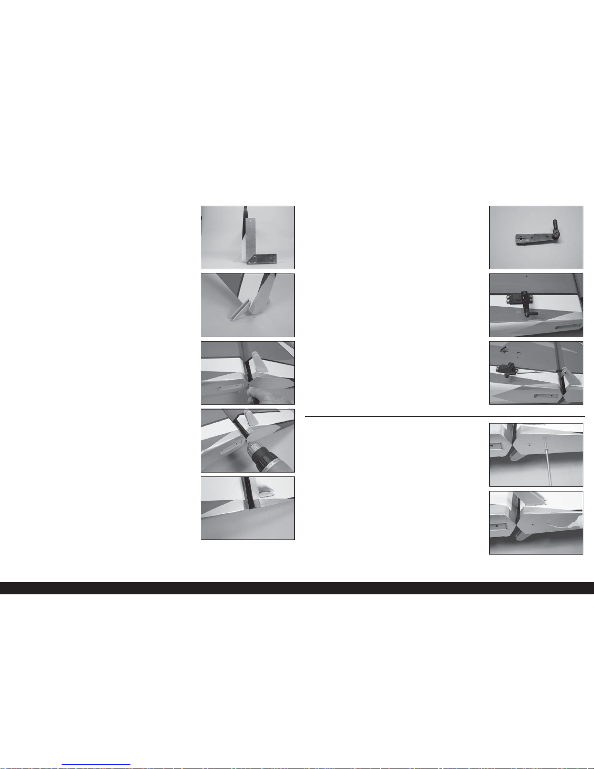
10. Assemble the rudder linkage using a 41/2-inch (114mm)
linkage and ball end. Attach the ball end to the control
horn using a 4-40 x 5/8-inch socket head cap screw and
4-40 locknut. Tighten the hardware using a 3/32-inch
hex wrench and 1/4-inch nut driver. Adjust the linkage so
the rudder is centered while the rudder servo is centered
using the radio system.
1. Thread a #4 x 5/8-inch self-tapping socket head cap
screw into the two pre-drilled holes in the bottom of the
rudder using a 3/32-inch hex wrench. Remove the screws
before proceeding.
2. Place 2 to 3 drops of thin CA in each hole to harden
the surrounding wood. Allow the CA to fully cure before
proceeding.
1.
2.
TAIL WHEEL INSTALLATION
5. Attach the rudder to the fi n using the hinge wire. Start the
wire in the bottom hinge by hand.
6. Attach a drill to the wire, then use the drill to install the
wire through the remaining hinges.
7. Complete the hinge wire installation by inserting the wire
so only 1/8-inch (3mm) of the wire protrudes beyond the
bottom of the rudder.
3. Prepare and install the rudder control horn, starting with
the upper horn. Check that the rudder rests perpendicular
to your work surface when the rudder is resting on the
control horn and hinge line as shown using a square.
8. Attach the ball link to the rudder servo arm.
4. Repeat the process to install the lower control horn. Allow
the epoxy to fully cure before proceeding.
9. Center the rudder servo using the radio system. Attach
the servo arm to the rudder servo perpendicular to the
servo center line.
8.
9.
10.
3.
4.
5.
6.
7.
17 EN
Extra 300 X 120cc
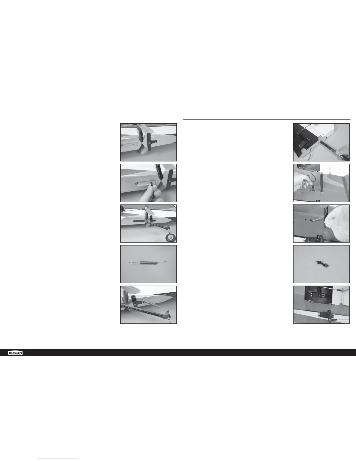
3. Attach the tiller arm to the bottom of the rudder using
two #4 x 5/8-inch self-tapping socket head caps screws.
Tighten the screws using a 3/32-inch hex wrench.
4. Thread a 6-32 x 3/4-inch socket head cap screw into
each of the blind nuts pre-installed in the fuselage. Clear
the threads using a 6-32 tap if the screws do not thread
in easily.
5. Attach the tail wheel bracket to the fuselage using two
6-32 x 3/4-inch socket head cap screws. Use a 7/64-inch
hex wrench to tighten the screws. Make sure to apply
thread lock to the screws to prevent them from vibrating
loose.
6. Bend a small loop 1-inch (25mm) from the end of the
springs at each end of the spring using pliers. Trim the
excess wire using side cutters. Prepare both springs at
this time.
7. Attach the spring coils to the rudder tiller arm and tail
wheel tiller arm. Bend the loops tightly against the tiller
arms to secure them in position.
3.
4.
5.
6.
7.
1. Slide the stabilizer tube into the socket in the stabilizer.
The tube will slide in easily, so don’t force it any more
than it will easily slide.
2. Slide the stabilizer tube into the fuselage. Connect the
extension for the elevator servo and tuck the extension
into the fuselage.
1.
2.
3.
4.
5.
STABILIZER INSTALLATION
3. Thread a 4-40 x 5/8 inch socket head screw into the blind
nuts. Use a 4-40 tape to clear the threads in the blind nut
if the screw does not thread in easily. Remove the screw
before proceeding.
4. Slide a #4 lock washer, the #4 washer on a 4-40 x 5/8-
inch socket head cap screw. Prepare all four screws at
this time.
5. Slide the stabilizer tight against the fuselage. Secure it
using two of the screws prepared in the previous step.
Use a 3/32-inch hex wrench to tighten the screws.
6. Repeat the previous steps to install the remaining
stabilizer.
18EN
1. Attach the landing gear to the fuselage using four 8-32
x 3/4-inch socket head cap screws, four #8 washers
and four 8-32 lock nuts. Use a 1/8-inch hex wrench and
11/32-inch nut driver to tighten the hardware. The gear
will angle forward slightly when installed.
2. Fit the landing gear fairing to the landing gear. There is
a right and left fairing, so make sure to check each side.
The front edge of the fairing will be roughly 3/4-inch
(19mm) rearward of the front edge of the fuselage to
allow clearance for the cowling.
3. Apply a bead of silicone adhesive ONLY where the fairing
fi ts against the fuselage. Slide the fairing into position,
and use low-tack tape to hold it in position until the
adhesive fully cures.
4. Attach the axle to the landing gear using the nut supplied
with the axle. With the fl at areas of the axle facing down,
tighten the axle using a 10mm and 1/2-inch wrench.
5. Slide a 5/32-inch wheel collar on the axle. Use the
supplied wrench to tighten the setscrew so the collar
is centered on the fl at area closest to the landing gear.
Make sure to use thread lock on the setscrew to prevent
it from vibrating loose.
1.
2.
3.
4.
5.
LANDING GEAR INSTALLATION
6. Place a drop of light machine oil on the axle, then slide
the wheel on the axle. Secure the wheel using a 5/32inch wheel collar, tightening the setscrew on the outer
fl at area. Make sure to use thread lock on the setscrew to
prevent it from vibrating loose.
7. Check the threads in the blind nut using a 4-40 x 1/2-
inch socket head cap screw. Attach the wheel pant to the
landing gear using two 4-40 x 1/2-inch socket head cap
screws, two #4 lock washers and two #4 washers. Use
a 3/32-inch hex wrench and thread lock when installing
the screws.
8. Repeat steps 2 through 8 to complete the opposite side of
the landing gear.
6.
7.
8.
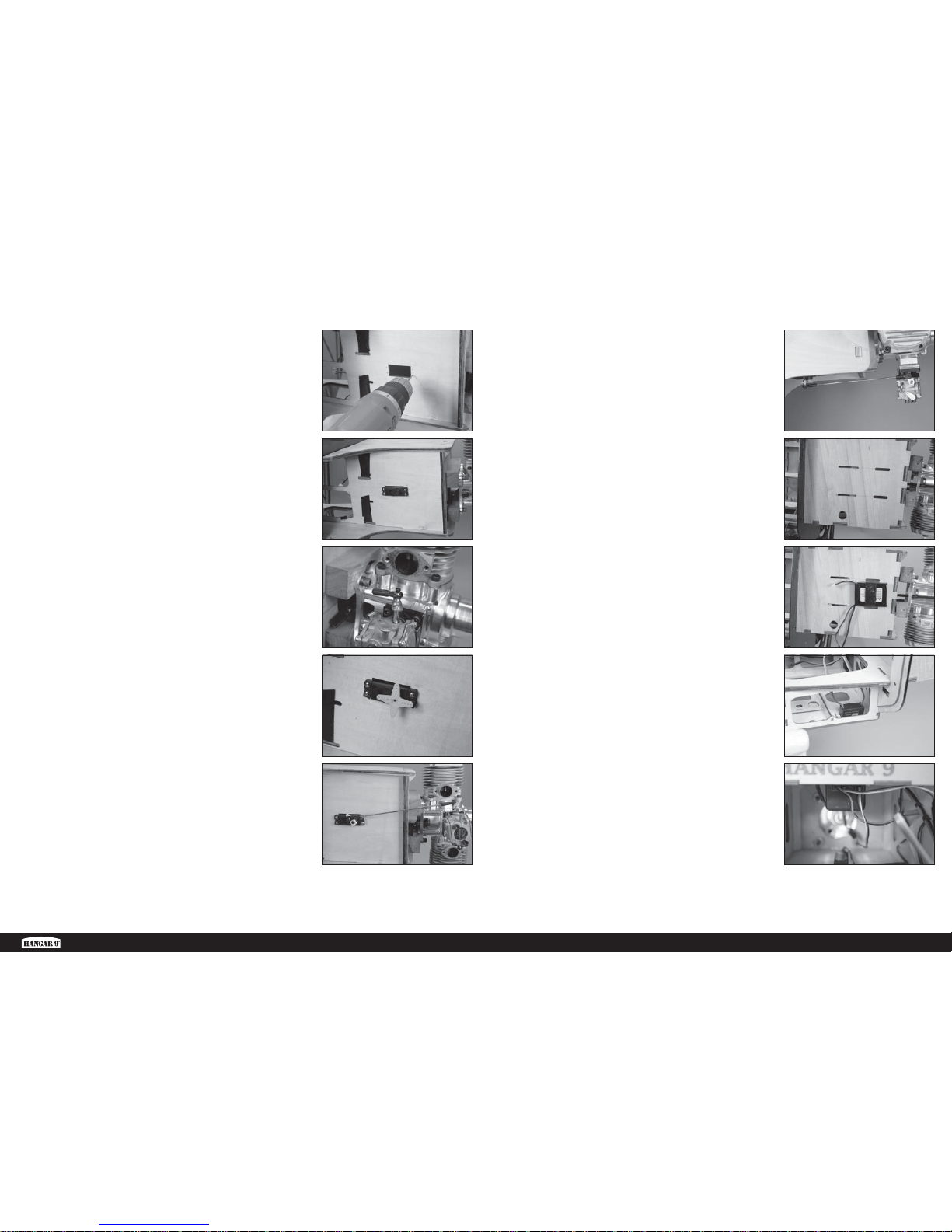
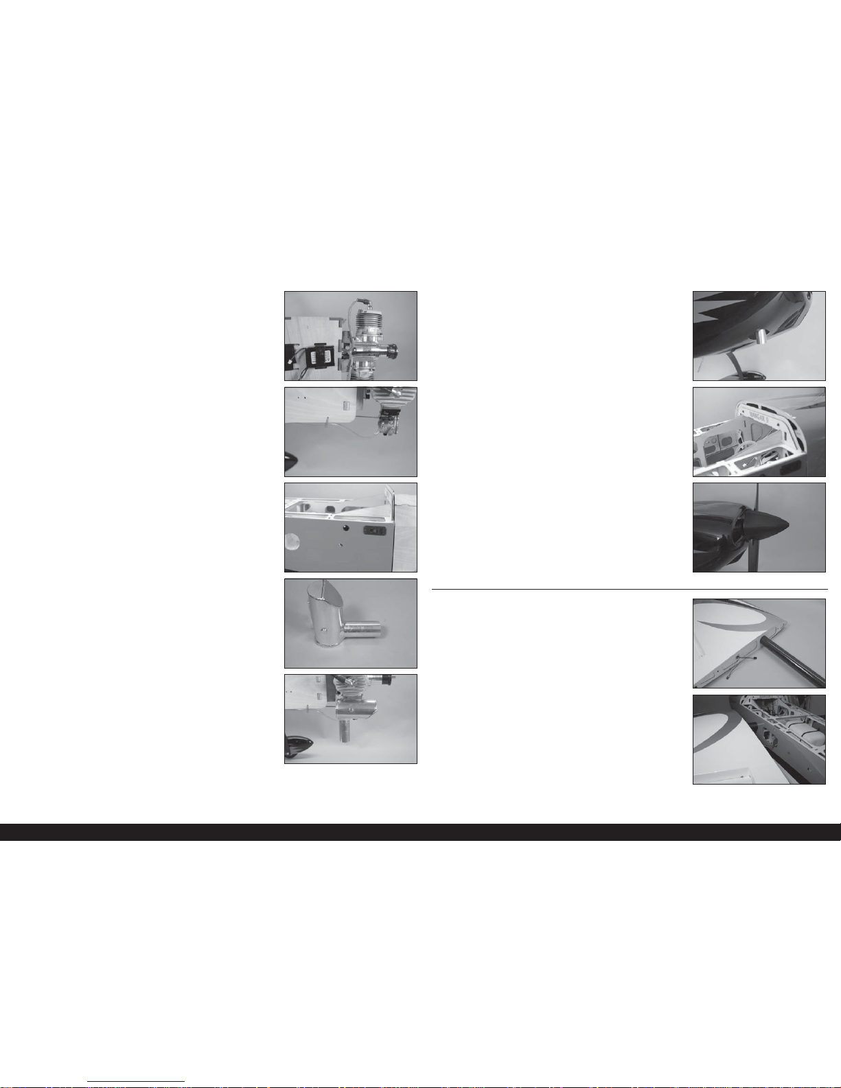
1. Mount the engine to the fi rewall using the two hardwood
spacers, four 1/4-20 x 2-inch socket head bolts and four
1/4-inch lock washers. Use thread lock and a 3/16-inch
hex wrench when installing the bolts.
2. Place the throttle servo in the opening in the bottom of
the engine box with the output facing the front of the
fuselage. Use a pencil to mark the locations for the servo
monting screws.
1.
2.
ENGINE INSTALLATION
19 EN
Extra 300 X 120cc
3. Drill the four servo mount holes using a drill and 5/64-
inch (2mm) drill bit.
4. Prepare the holes for the servo mounting screws by
threading a screw into each hole, then removing the
screw. Place 2 to 3 drops of thin CA in each hole and
allow the CA to fully cure. Mount the servo in the fuselage
using the screws included with the servo. Connect the
servo to the receiver using a 24-inch (600mm) servo
extension.
5. Attach the ball end to the carburetor throttle lever using a
4-40 x 5/8-inch socket head cap screw, conical washer
and 4-40 lock nut. Drill the hole in the carburetor throttle
arm if necessary using a 7/64-inch drill bit.
6. Turn on the radio system. Center the throttle stick and
trim at the transmitter. Place the servo arm on the throttle
servo perpendicular to the servo centerline.
7. Use the manual included with the engine for the ball link
position at the servo. Move the servo to low throttle and
install the linkage. Adjust the linkage so the carburetor is
closed. Check the operation of the carburetor using the
radio system and make any adjustments necessary to
achieve full throttle.
8. When the linkage is installed, it will run parallel to the
bottom of the engine box.
9. Cut two additional 1
1
/2-inch slots 11/2 inches behind the
slots in the top of the engine box. Use a hobby knife
equipped with a #11 blade to cut the slots.
10. Secure the ignition battery to the top of the engine
box using a hook and loop strap. Place foam between
the battery and plywood to protect the battery from
vibrations. Route the leads from the battery through the
hole in the top of the engine box.
8.
9.
10.
11.
12.
3.
4.
5.
6.
7.
11. Remove the covering from the fuselage side using a
hobby knife equipped with a #11 blade. Mount the
ignition switch using the hardware included with the
switch. Secure the lead from the battery to the switch.
12. Secure the ignition module inside the engine box using a
hook and loop strap. Place foam between the module and
plywood to protect the module from vibrations.
20EN
13. Route and connect the leads necessary to operate the
engine. Use tie wraps to secure the leads so they don’t
interfere with the operation of the engine or become
disconnected accidentally.
14. Attach the fuel line from the clunk to the carburetor inlet.
Use a commercially available fastener or tie wrap to
secure the fuel line so it does not disconnect in fl ight.
15. Also install a fuel fi ller so the fuel tank can be fi lled and
drained without the need to remove the cowling or hatch.
16. Cut the exhaust stacks on the muffl er to a length of 2
3
/8
inches (61mm). This will make it easier to install the
cowling over the muffl er stacks.
Î Install one muffler at a time to make
trimming the cowling easier.
17. Attach the muffl ers to the engine using the hardware
included with the muffl ers.
13.
14.
15.
16.
17.
18. Cut the cowling to fi t over the muffl er exhaust stacks.
Work slowly for the best results.
19. Slide the cowling into position and secure it use six 4-40
x 3/4-inch socket head cap screws and six #4 washers.
Tighten the screws using a 3/32-inch hex wrench.
20. Attach the propeller and spinner to the engine. Follow
any instructions provided with the engine manufacturer
regarding preparing the propeller or spinner before
installation.
18.
19.
20.
1. Slide the wing tube into the wing tube socket.
2. Slide the wing panel into position, guiding the extensions
from the wing into the fuselage.
1.
2.
WING INSTALLATION
21 EN
Extra 300 X 120cc
3. Attach the wing panels to the fuselage using two ¼-20 x
2 nylon wing bolts. Install the wing bolt near the trailing
edge, leaving it slightly loose.
4. Install the 1/4-20 x 2 nylon wing bolt near the leading
edge of the wing. Tighten both wing bolts at this time to
secure the wing to the fuselage.
5. Repeat the previous steps to install the remaining wing
panel.
1. Sand the bottom of the pilot using medium grit
sandpaper, then clean the sanded area using a paper
towel and isopropyl alcohol. Secure the pilot in the
cockpit using 30-minute epoxy. Allow the epoxy to fully
cure before proceeding.
2. Attach the canopy to the fuselage using the hardware
removed earlier in the manual.
5.
6.
CANOPY AND PILOT INSTALLATION
3.
4.
1. Remove the covering to expose the pre-installed blind nut
in the wing tip using a hobby knife equipped with a #11
blade.
2. Thread a 6-32 x 3/4-inch button head machine screw into
each of the blind nuts. Clean the threads using a 6-32 tap
if the screw does not thread in easily. Remove the screws
before proceeding.
3. Apply a drop of canopy glue on each of the 6-32 x ¾-inch
button head machine screws to keep them from vibrating
loose, yet still removable. Attach the side force generator
to the wing tip using two 6-32 x 3/4-inch button head
machine screws and two #6 washers. Use a 3/32-inch
hex wrench to tighten the screws.
1.
2.
3.
SIDE FORCE GENERATOR INSTALLATION (OPTIONAL)
22EN
1. Apply the decals to your model using the photos located in this section of the manual and the box art from your
model. Use a spray bottle and a drop of dish washing liquid or glass cleaner sprayed in the location of the decal to
allow repositioning of the decal. Use a paper towel as a squeegee to remove excess water from under the decal.
Allow the model to rest overnight so the remaining water can evaporate.
DECAL INSTALLATION
 Loading...