

Page 1
35% Extra 300 ARF
Assembly Manual
Page 2
Notice
All instructions, warranties and other collateral
documents are subject to change at the sole discretion
of Horizon Hobby, Inc. For up-to-date product
literature, visit http://www.horizonhobby.com and click
on the support tab for this product.
Meaning of Special Language
The following terms are used throughout the product
literature to indicate various levels of potential harm
when operating this product:
NOTICE: Procedures, which if not properly followed, create
a possibility of physical property damage AND a little or no
possibility of injury.
CAUTION: Procedures, which if not properly followed,
create the probability of physical property damage AND a
possibility of serious injury.
WARNING: Procedures, which if not properly followed,
create the probability of property damage, collateral damage,
and serious injury OR create a high probability of superficial
injury.
WARNING: Read the ENTIRE instruction manual to
become familiar with the features of the product before
operating. Failure to operate the product correctly can result
in damage to the product, personal property and cause
serious injury.
This is a sophisticated hobby product and NOT a toy. It must
be operated with caution and common sense and requires
some basic mechanical ability. Failure to operate this Product
in a safe and responsible manner could result in injury or
damage to the product or other property. This product is not
intended for use by children without direct adult supervision.
Do not attempt disassembly, use with incompatible
components or augment product in any way without the
approval of Horizon Hobby, Inc. This manual contains
instructions for safety, operation and maintenance. It is
essential to read and follow all the instructions and warnings
in the manual, prior to assembly, setup or use, in order to
operate correctly and avoid damage or serious injury.
Table of Contents
Intro ................................................................................. 2
Product Support ..............................................................2
Specifications ................................................................... 2
Included Parts ................................................................. 3
Contents of Kit and Parts Number .................................... 4
Safety Precautions and Warnings .................................... 4
35% Extra 300 Operating Recommendations ..................5
Important Information Regarding Warranty .....................5
Using the Manual ............................................................. 5
Aileron Servos Installation ............................................... 7
Elevator Servo Installation ............................................. 11
Rudder Installation ......................................................... 13
Tail Wheel Assembly Installation .................................... 14
Rudder Servo Installation .............................................. 15
Main Gear and Wheel Pants Installation ......................... 17
Engine and throttle Servo Installation ............................19
In-Cowl Mufflers Installation ..........................................22
Canisters Installation ...................................................... 23
Tuned Pipe Installation .................................................. 25
Receiver and Ignition Battery Installation ....................... 28
Ignition Module, Switch and Regulator Installation ........ 29
Fuel Tank, Fill and Over Flow Installation ........................31
Cowl Mounting ............................................................... 33
Pilot Installation ............................................................. 33
Receiver, Switch and throttle Servo
Regulator Installation ..................................................34
Satellite Receivers Installation ....................................... 36
Center of Gravity ............................................................ 37
Control Throws .............................................................. 37
Applying Decals .............................................................38
Preflight ......................................................................... 39
Range Test Your Radio ................................................... 39
Safety Do’s and Don’ts for Pilots ....................................39
Daily Flight Checks ......................................................... 39
Warranty and Repair Policy ............................................ 40
Warranty Services .......................................................... 40
Compliance Information for the European Union ........... 41
2011 Official Academy of
Model Aeronautics Safety Code .................................42
Intro
Pulling from the success of its predecessor, designer Mike
McConville built on strengths of the popular 35% Extra 260
to create the new Extra 300, which is undoubtedly his best
Extra design yet.
With improved aerodynamic design, and a completely
reengineered structure, the Extra 300 offers straight and true
flight performance in an airframe designed to stand up to the
most extreme acrobatic routines.
Ideal for IMAC competition, freestyle flying or extreme 3D,
the Extra will not disappoint.
Finished in a new trim scheme from the creative mind of
Mike Hilderbrandt, the Extra is as visible in the air as it is
beautiful on the tarmac.
All guess work has been taken out of this ARF— the most
popular engine and exhaust choices are covered in this
manual.
The Hangar 9® 35% Extra 300 sets a new standard for giant
—scale: ease of assembly and world class performance.
Enjoy your new 300 and many happy landings.
Product Support
For technical assistance with this product, please contact the
appropriate Horizon Product Support office.
Specications
Wingspan 105 in (2.7 m)
Length 98.0 in (2.5 m)
Wing Area 2003 sq in (129.2 sq dm)
Weight 27.0–30.0 lb (12.2–13.6 kg)
Transmitter & Servos
4-channel (or greater) with 8 servos
Engine 100cc - 120cc gas engine
2 35% Extra 300 ARF Assembly Manual2
Page 3
PACKAGED IN KIT
Fuselage with hinged rudder 1
Right horizontal stabilizer with hinged elevator 1
Left horizontal stabilizer with hinged elevator 1
Wings with hinged aileron 1
Cowl 1
HARDWARE BAGS
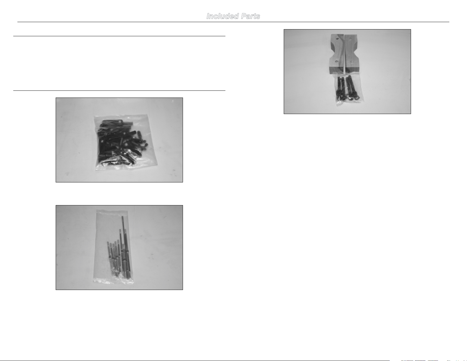
Included Parts
Engine standoffs and bolts
Ball Links include 4-40 screws, locknuts and conical spacers
Pushrods
335% Extra 300 ARF Assembly Manual
Page 4
21
8
2
Safety Precautions and Warnings
10
1
15
9
4
3
14
5
13
6
7
Read and follow all instructions and safety precautions
before use. Improper use can result in fire, serious injury
and damage to property.
COMPONENTS
Use only with compatible components. Should any
compatibility questions exist please refer to the product
instructions, the component instructions or contact Horizon
Hobby, Inc.
FLIGHT
Fly only in open areas to ensure safety. It is recommended
flying be done at AMA (Academy of Model Aeronautics)
approved flying sites. Consult local ordinances before
choosing a flying location.
PROPELLER
Keep loose items that can get entangled in the propeller
away from the prop, including loose clothing, neck strap or
other objects such as pencils and screwdrivers. Especially
keep your hands away from the propeller as sever injury can
occur. Using a thick glove is highly recommended.
BATTERIES
Notes on Lithium Polymer Batteries
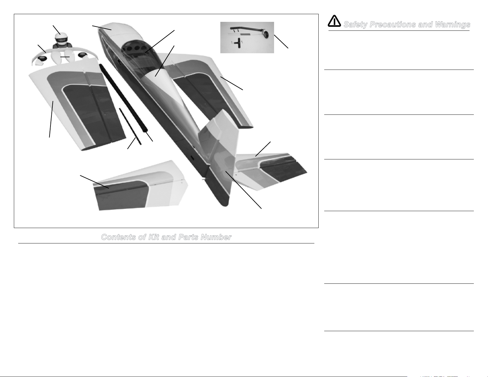
Contents of Kit and Parts Number
Replacement Parts
1. HAN105501 Fuselage w/Hatch 35% Extra 300 ARF
2. HAN105502 Hatch w/Canopy, 35% Extra 300 ARF
3. HAN105503 Left Wing Panel, 35% Extra 300 ARF
4. HAN105504 Right Wing Panel, 35% Extra 300 ARF
5. HAN105505 Left Stab Panel, 35% Extra 300 ARF
6. HAN105506 Right Stab Panel, 35% Extra 300 ARF
7. HAN105507 Rudder w/Horn, 35% Extra 300 ARF
8. HAN105509 Painted Cowl, 35% Extra 300 ARF
9. HAN105510 Wheel Pant Set, 35% Extra 300 ARF
10. HAN105511 Painted Landing Gear, 35% Extra 300 ARF
11. HAN105512 Linkage Hdwr Set, 35% Extra 300 ARF
12. HAN105513 Assembled Gas Tank, 35% Extra 300 ARF
4 35% Extra 300 ARF Assembly Manual
Replacement Parts
13. HAN105514 Carbon Wing Tube, 35% Extra 300 ARF
14. HAN105514 Carbon Stab Tube, 35% Extra 300
15. HAN105515 Tailwheel Unit, 35% Extra 300 ARF
16. HAN105516 Main Axle Set, 35% Extra 300 ARF
17. HAN105517 Exh/Batt Mount Set, 35% Extra 300 ARF
18. HAN105518 Cowl/Canopy Screws; 35% Extra 300 ARF
19. HAN105519 Decal Set, 35% Extra 300 ARF
20. HAN105520 Nylon Wing Bolts, 35% Extra 300 AEF
21. HAN376 35% Painted Pilot Helmet Extra 300
When misused Lithium Polymer batteries are significantly
more volatile than alkaline or Ni-Cd/Ni-MH batteries used
in RC applications. Always follow the manufacturer’s
instructions when using and disposing of any batteries.
Mishandling of Li-Po batteries can result in fire and rupture
causing serious injury and damage.
SMALL PARTS
This kit includes small parts and should not be left
unattended near children as choking and serious injury could
result.
Age Recommendation:
For advanced fliers ages 14 and above. This is not a toy.
Page 5

35% Extra 300 Operating Recommendations
• Inspectyourmodelbeforeeveryflighttomakecertainit
is airworthy.
• Beawareofanyotherradiofrequencyuserwhomay
present an interference problem.
• Alwaysbecourteousandrespectfulofotherusersof
your selected flight area.
• Chooseanareaclearofobstaclesandlargeenoughto
safely accommodate your flying activity.
• Makecertainthisareaisclearoffriendsandspectators
prior to launching your aircraft.
• Beawareofotheractivitiesinthevicinityofyourflight
path that could cause potential conflict.
• Carefullyplanyourflightpathpriortolaunch.
• AbidebyanyandallestablishedAMANationalModel
Aircraft Safety Code.
Important Information
Regarding Warranty
Please read our Warranty and Liability Limitations section
before building this product. If you as the purchaser or user
are not prepared to accept the liability associated with the
use of this Product, you are advised to return this Product
immediately in new and unused condition to the place of
purchase.
Using the Manual
This manual is divided into sections to help make assembly
easier to understand, and to provide breaks between each
major section. In addition, check boxes have been placed
next to each step to keep track of each step completed.
Steps with a single box () are performed once, while
steps with two or more boxes () indicate that the step
will require repeating, such as for a right or left wing panel,
two servos, etc. Remember to take your time and follow the
directions.
UltraCote® Covering Colors
•White HANU870
•TrueRed HANU866
•Silver HANU881
Recommended Setup–2-Stroke Gas
•DA100
•DA-120
Recommended Spinner
4 1/2-inch silver Tru-Turn Ultimate Style with solid
backplate.
•DA120,TT-4552-B-M-DA120(2-BladedProp)
•DA120,TT-4553-B-M-DA120(3-BladedProp
Optional Tuned Pipe and Canister
Installation
If you are installing the optional tuned pipe, the following
items will be required:
•50mmdropheader,111/2-inchlongfortunedpipe
(MTW, RE2) and 10-inch for canister (MTW TD75)
•Clamps
•Couplers
Transmitter Requirements
The 35% Extra 300 requires a minimum of a 4-channel radio
to operate all the functions of your aircraft. However to get
the best performance from the Extra, a radio with mixing
functions is recommended. We suggest the following radio
system available through Horizon Hobby or your local hobby
distributor.
Spektrum DX8 SPM8800
Spektrum DX10t SPM2800US SPM2800
JR DSM2 or DSMX systems
Radio Equipment Requirements
The following items are recommended when installing the
9-Channel AR9110 (SPMAR9110) in your aircraft:
DS8911HV Digital Servo (7) JRPS8911HV
JR 537 Servo (1) JRPS537
3-inch Servo Extension (1) (Regulator) JSP98100
18-inch Servo Extension (2) (RX to Ailerons) JRPA099
24-inch Servo Extension (1) (Throttle) JRPA102
24-inch Servo Extension (2) (Ailerons) JRPA102
24-inch Servo Extension (1) (Rudder) JRPA102
36-inch Servo Extension (2) JRPA103
(2) Receiver Packs, 4000mAh Spektrum SPMB4000LP
Ignition Pack 2000mAh Spektrum SPMB2000LP
JR Charge Switch JRPA004
JR MatchBox (2) JRPA900
JR 5203 Regulator (2) JRPVR5203
535% Extra 300 ARF Assembly Manual
Page 6
Additional Required Tools
Additional Required Adhesives
Rotary too
Cut-off wheel Sanding drum
Drill Epoxy brush
Felt-tipped pen Ruler
Hex wrench: 1.5mm, 3mm, 4mm, 4.5mm, 3/32-inch, 5/32-
inch Iron
Hobby knife with #11 blade Mixing cup
Mixing stick Paper towel
Pencil Hemostat
Shoo Goo or Zap-A-Dap-A-Goo
Phillips screwdriver: #1, #2 Pin vise
Vise grip Masking tape
Rubbing alcohol
Nut driver: 1/4-inch, 1/2-inch, 9mm
Heat gun
Drill bit: 1/16-inch (1.5mm), 5/64-inch (2mm),
3/32-inch (2.5mm), 3/16-inch (5mm), 1/4-inch
(6.35mm)
Medium CA (PAAPT02)
Thin CA (PAAPT08)
CA remover/debonder (PAAPT16)
CA accelerator (PAAPT15)
Blue Threadlock (PAAPT42)
30-Minute Epoxy, 8 oz (PAAPT39)
Before Starting Assembly
Before beginning the assembly of your model, remove
each part from its bag for inspection. Closely inspect the
fuselage, wing panels, rudder and stabilizer for damage. If
you find any damaged or missing parts, contact the place of
purchase.
If you find any wrinkles in the covering, use a heat gun or
covering iron to remove them. Use caution while working
around areas where the colors overlap to prevent separating
the colors.
HAN100 – Heat Gun
HAN150 – Covering Glove
HAN101 – Sealing Iron
HAN141 – Sealing Iron Sock
6 35% Extra 300 ARF Assembly Manual
Page 7
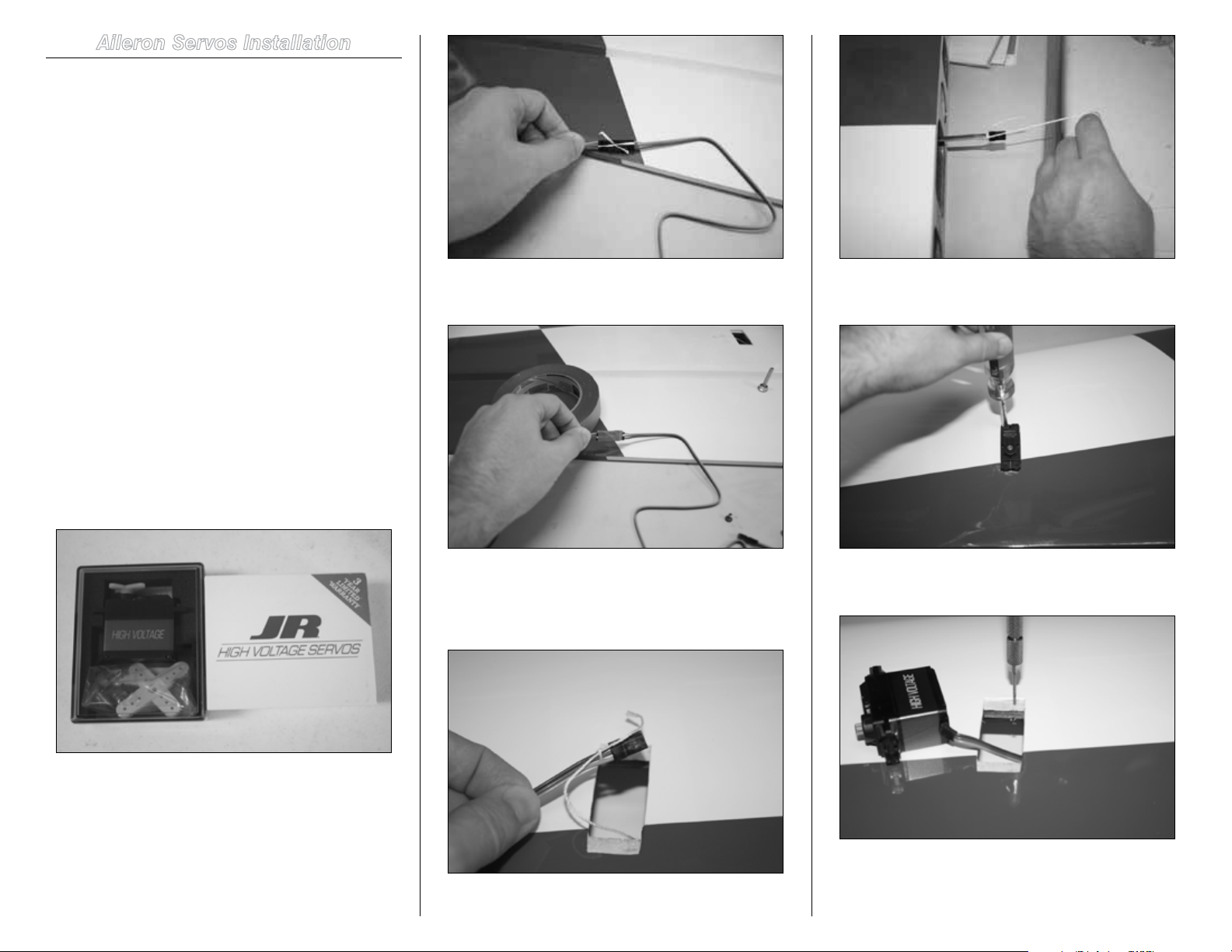
Aileron Servos Installation
Required Parts
Wing panel Ball link (4)
Control horns (4)
Aileron pushrod (4)
Required Parts (not included)
JR 8911HV with hardware (4) or similar digital servo
JR 1-1/4-inch servo arm (4)
JR heavy-duty servo extension, 24-inch (2)
JR MatchBox™ (2)
Required Tools and Adhesives
Pin vise
Thin CA Phillips screwdriver: #1
Drill bit: 1/16-inch Masking tape
Adhesive-backed hook and loop
3/32-inch ball driver Scissors
Dental floss (string)
1. Prepare the aileron servos by installing the rubber
grommets and brass eyelets.
Hint: Prepare all servos for the wing at this time.
3. Apply a piece of masking tape around the connector
and over the string.
5. Mount the servo so the output shaft is facing toward
the trailing edge and mark the servo mounting lugs location.
2. Secure a 24-inch servo extension to the outboard
aileron servo lead using string or a commercially available
connector. This will prevent the extension from accidentally
disconnecting inside the wing.
4. A string has been installed in the wing to pull the
aileron servo extension through the wing. Tie or tape the
string to the end of the extension and pull the lead to the
wing root.
6. Remove the servo. Using a pin vise, drill the servo
mounting screw locations.
7. In order to harden the servo mounting holes in
the bays, mount the servo screws, back them out and
apply some thin CA in the hole. Wait until CA is dry before
735% Extra 300 ARF Assembly Manual
Page 8
installing the servo.
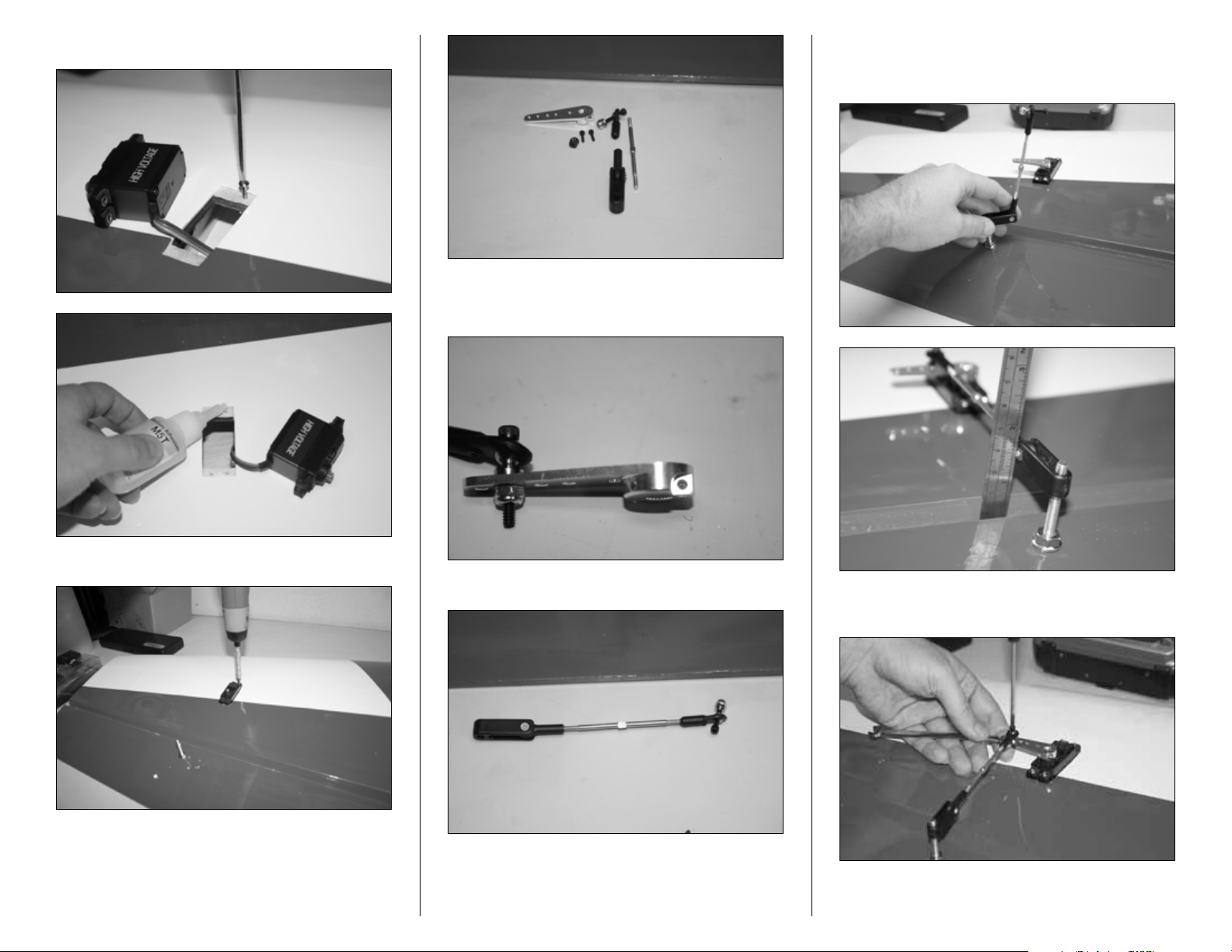
11. Screw on the control horn so the distance from
the hinge line to the center of the pivot point measures 1
1/2-inch.
Order of ball link assembly is bolt through the ball link,
conical spacer with flat end facing the servo arm, servo arm
and then nut.
8. Install the servo.
10. Attach the linkage to control horn and ball link.
12. Attach the ball link to 1 1/4-inch servo arm hole; in
case of JR servo arm, this is the second outermost hole.
9. Prepare the linkages and servo arm for outboard
servo installation.
13. Connect the servo to the MatchBox and receiver,
with radio sub-trim at 0, install the servo arm onto the servo
8 35% Extra 300 ARF Assembly Manual
Page 9
on the spline that gets it as close to parallel to the hinge line
as possible. If necessary, use the sub trim in the transmitter
to adjust the neutral position so the arm is parallel to the
hinge line. Attach the linkage to the servo arm and adjust the
length using a Hangar 9 Pro-Link™ adjustment tool so the
aileron is at the neutral position.
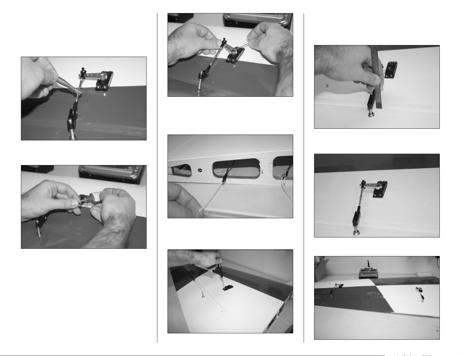
14. Apply a drop of threadlock on the servo arm center
screw and tighten.
18. Assemble the servo linkage following the same
steps as the outboard servo. Make sure to set the distance of
center of the control horn pivot to the aileron hinge at 1 1/2
inch.
16. Mount the inboard servo following the same
method as outboard but no extension is required. Tie a knot
using the string that has been attached to the servo bay and
pull the servo lead through the root rib as shown.
19. Connect the servo to the Matchbox and refer to the
MatchBox Programming Hints on page 10 for final setup.
15. Tighten the servo arm setscrews. Do not use
threadlock on these screws.
17. Mount the servo so that the output shaft is toward
the trailing edge. Follow the same steps in marking and
making the servo mounting holes as the outboard servo.
20. The picture below shows both servos installed.
935% Extra 300 ARF Assembly Manual
Page 10
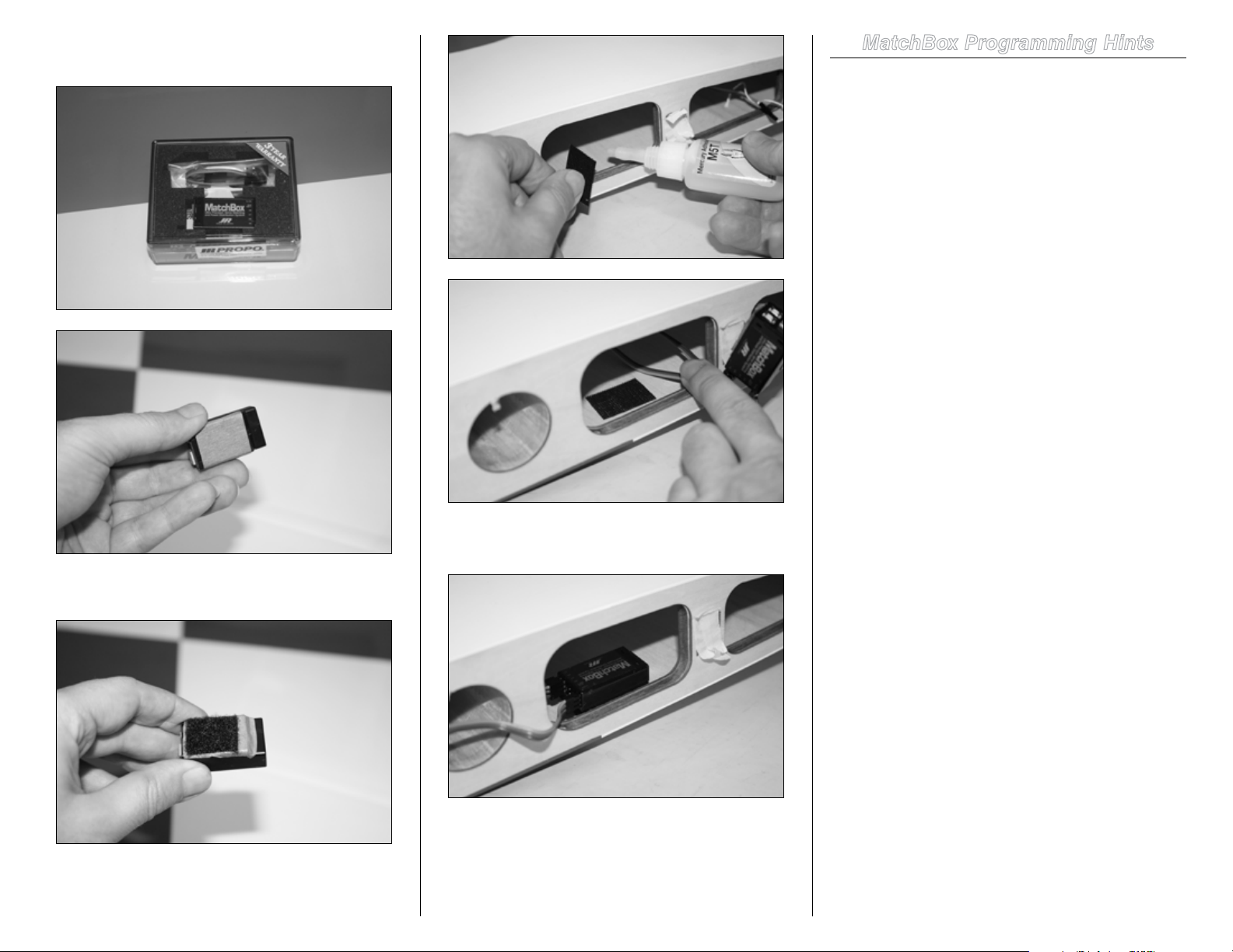
21. Apply a piece of masking tape to the back of the
MatchBox.
22. Glue a piece of hook and loop using CA to the
masking tape.
24. Connect the inboard and outboard servo leads to the
MatchBox and mount the MatchBox in the root.
MatchBox Programming Hints
The pointers below can help make matching servos easier.
This is not to take the place of the MatchBox instruction
manual.
1. Connect the outboard servo to the MatchBox and then
make all adjustments to servo center and travel adjustments
in the transmitter programming. No adjustments to this
servo should be made in the MatchBox.
2. Connect the inboard servo to the MatchBox, then
install the servo arm onto the servo on the spline that gets
it as close to parallel with the hinge line as possible. Then
use the MatchBox to set the center of this servo so the
servo arm is exactly parallel to the hinge line. Now adjust the
linkage length so the hole in the ball link directly aligns with
the appropriate hole in the servo arm.
Deflect the servo to full stick in one direction and use the
MatchBox to set the endpoint so the ball link directly lines
up with the hole in the servo arm. Repeat this with the stick
fully deflected in the opposite direction. Once the center and
both endpoints are set for the second servo, remember to
turn the dial on the MatchBox back to the 0 position to save
the settings before powering off the receiver. Hint, when
adjusting for endpoints (full deflection), it is hard to hold the
sticks and adjust the MatchBox at the same time. It is best to
move the sticks to full deflection and while holding the stick,
turn off the radio. This will put the receiver into hold and
makes adjustment easier working only the MatchBox and
observing the linkage position over the servo arm.
23. Glue opposite side of hook and loop using CA to
the root of the wing panel.
10 35% Extra 300 ARF Assembly Manual
Page 11
Elevator Servos Installation
Required Parts
Elevator panel
Ball link (2)
Control horns (2)
Elevator pushrod (2)
Required Parts (not included)
JR 8911HV or similar digital servo (2)
JR 1 1/2-inch servo arm (2)
JR heavy-duty servo extension, 36-inch (2)
Required Tools and Adhesives
Pin vise
Thin CA Phillips screwdriver: #1
Drill bit: 1/16-inch Masking tape
String (Dental floss)
3/32-inch ball driver
Note: It is important to go over the covering with
covering iron and make sure all the seams are sealed.
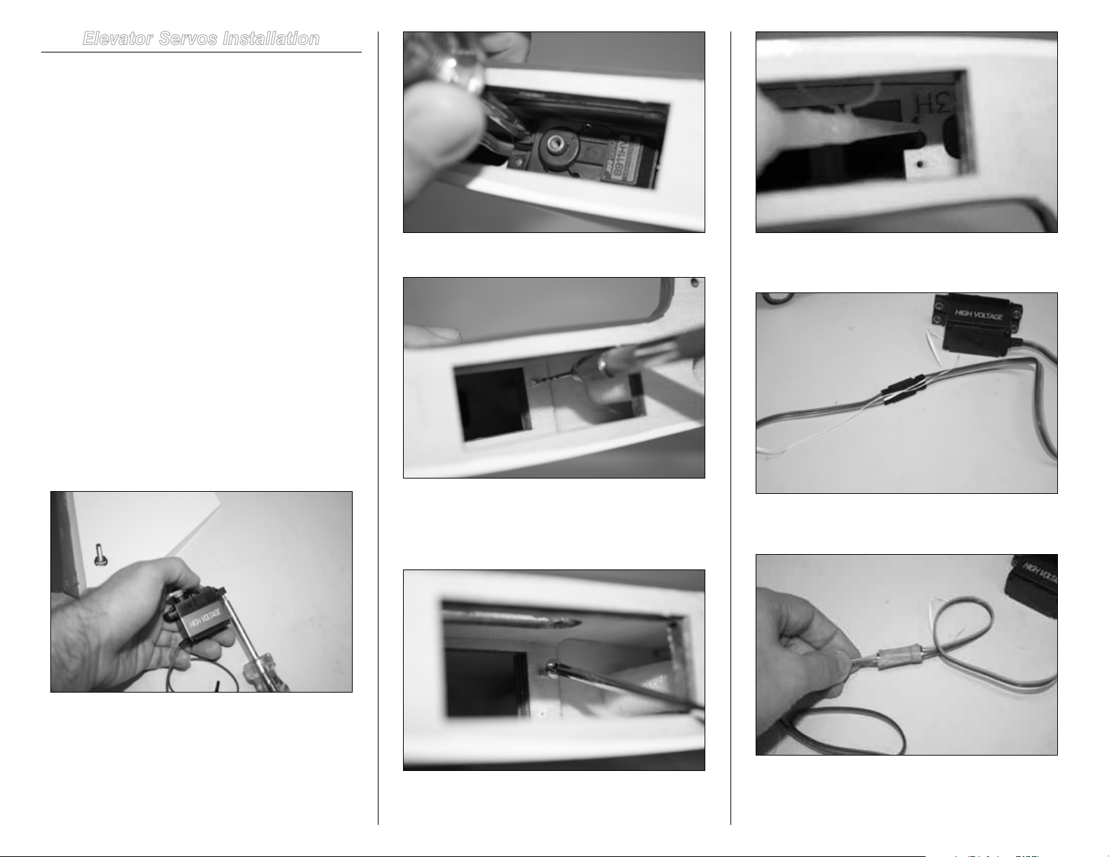
3. Using a pin vise, drill the servo mounting screw.
5. Secure a 36-inch JR Heavy-Duty extension using a
string or commercially available safety connector.
1. Prepare the servo by installing the rubber grommets
and brass eyelets.
The servo needs to be installed in such a way that the output
shaft is towards the leading edge of the stab. The servo arm
needs to be 1 1/2 inch. If using a JR aluminum servo arm,
this would be the third outermost hole.
2. Mount the servo and mark the servo mounting
holes.
4. In order to harden the servo mounting holes in
the bays, mount the servo screws, back them out and
apply some thin CA in the hole. Wait until CA is dry before
installing the servo.
6. Apply a piece of masking tape over the knot holding
the leads.
7. For removable stab setup, do not connect the
extension to the elevator servo, instead run a 36-inch
extension through the fuselage and exit from stab mounting
1135% Extra 300 ARF Assembly Manual
Page 12
hole. Use a commercially available safety connector instead
of the string and masking tape to secure the connector.
8. Mount the servo so that the output shaft is closer to
the leading edge of the elevator. Pass the extension through
the slot provided in the root of the elevator panel.
9. Prepare the linkage and control horn for installation.
10. Screw on the control horn so that the distance
from the elevator hinge line to the center of the pivot point of
the horn is 1 3/8 inch.
12. Mount the servo arm so it is perpendicular to
the center line of the stab, make adjustment to sub-trim if
necessary.
11. Power up the servo by connecting it to the receiver. With
The picture below shows the slot that extension needs to exit
from.
12 35% Extra 300 ARF Assembly Manual
radio sub-trim set at 0.
Page 13
13. Apply a drop of threadlock to the servo center
screw and tighten the screw. This is the outer hole in the JR
Aluminum arm.
15. Connect the ball link to 1 1/2-inch servo arm. In
case of JR Aluminum servo arm, this is the outermost hole.
Insert the ball link screw into the ball link through the conical
spacer (flat surface facing the arm) and servo arm and then
nut.
Rudder Installation
Required Parts
Fuselage Rudder
Hinge rod
Required Tools and Adhesives
Drill Pliers
Petroleum Jelly/Industrial lubricant
1. Apply some industrial lubricant to the rod. Pass the
rod through the hinges in the rudder and fuselage vertical fin
separately. This helps remove any possible dirt in the hinges
and makes for easier final assembly.
14. Tighten the servo arm setscrews. Move the servo
arm all the way to the front and back to access the mounting
lugs.
16. With servo arm perpendicular to the center line
of the stab, use a Hangar 9 Pro-Link Wrench to adjust the
linkage so the elevator is at neutral position.
2. Mate the rudder and fuselage vertical stabilizer
and carefully pass the rod through hinges. This can be
accomplished by two ways. 1. Use a drill on slow speed
and gently pass through the rod. If there is any resistance,
back out and repeat. 2. Use a pair of pliers and push the rod
through the hinges. Make sure not to buckle the rod. This is
a rather slow process and needs attention.
1335% Extra 300 ARF Assembly Manual
Page 14
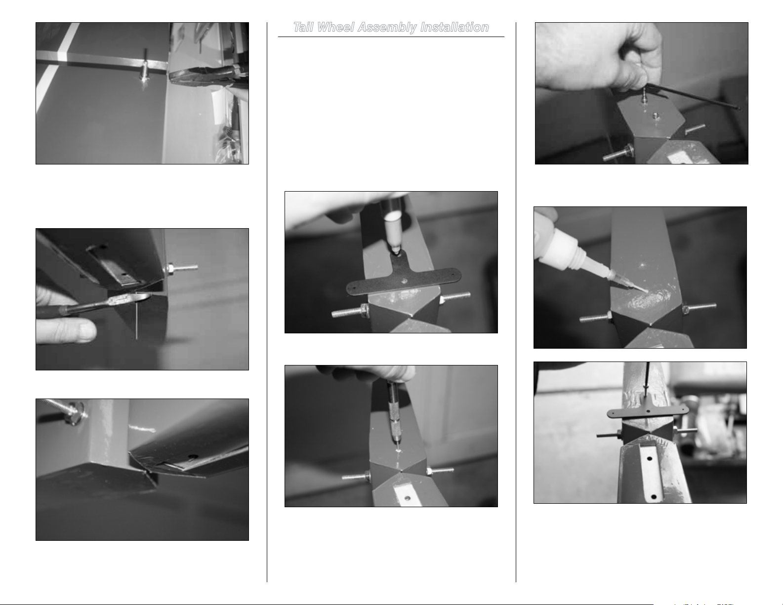
Tail Wheel Assembly Installation
Required Parts
Tail gear and screws Springs
T-bracket and screws
Required Tools and Adhesives
2.5mm and 7/64-inch ball driver
Blue threadlock Felt-tipped pen
Thin CA Pin vise
3. Cut excess rod long enough (1mm) that it is easy to
grab and pull out when needed for transportation. The tail
wheel bracket will stop the rod from backing out of the
hinges.
The picture below shows the rod when cut.
1. Mount the T-bracket so it is parallel to the rudder horn
bolt and mark using a felt-tipped pen.
2. Using a pin vise, drill the marked spots.
4. To harden the wall, apply some thin CA into the holes.
Wait until CA is dry before installing the T-bracket.
3. Mount the sheet metal screws provided and back them
out.
14 35% Extra 300 ARF Assembly Manual
5. Apply threadlock to the tail gear bolts.
Page 15

Rudder Servo Installation
Required Parts
Fuselage
Ball link (1)
Rudder pushrod (1)
Required Parts (not included)
JR 8911HV or similar digital servo (1)
JR 1.5-inch servo arm (1)
JR heavy-duty servo extension, 24-inch (1)
6. Mount the tail gear.
7. Hook the springs to the T-bracket from the tiller arm.
Pass through the hole and wrap the spring around the arm a
couple of times.
Required Tools and Adhesives
Pin vise Phillips screwdriver: #1
String (Dental floss)
3/32-inch ball driver
Note: The fuselage is made to accept 2 rudder servos,
however if the recommended servo is used, only one
servo is needed even for the most extreme 3D flying.
For lower torque servo, use two servos.
1. Prepare the servo by installing the rubber grommets
and brass eyelets. Attach the 24-inch extension and secure
the connector with a piece of dental floss (string).
3. Mount the servo so the output shaft is closer to the
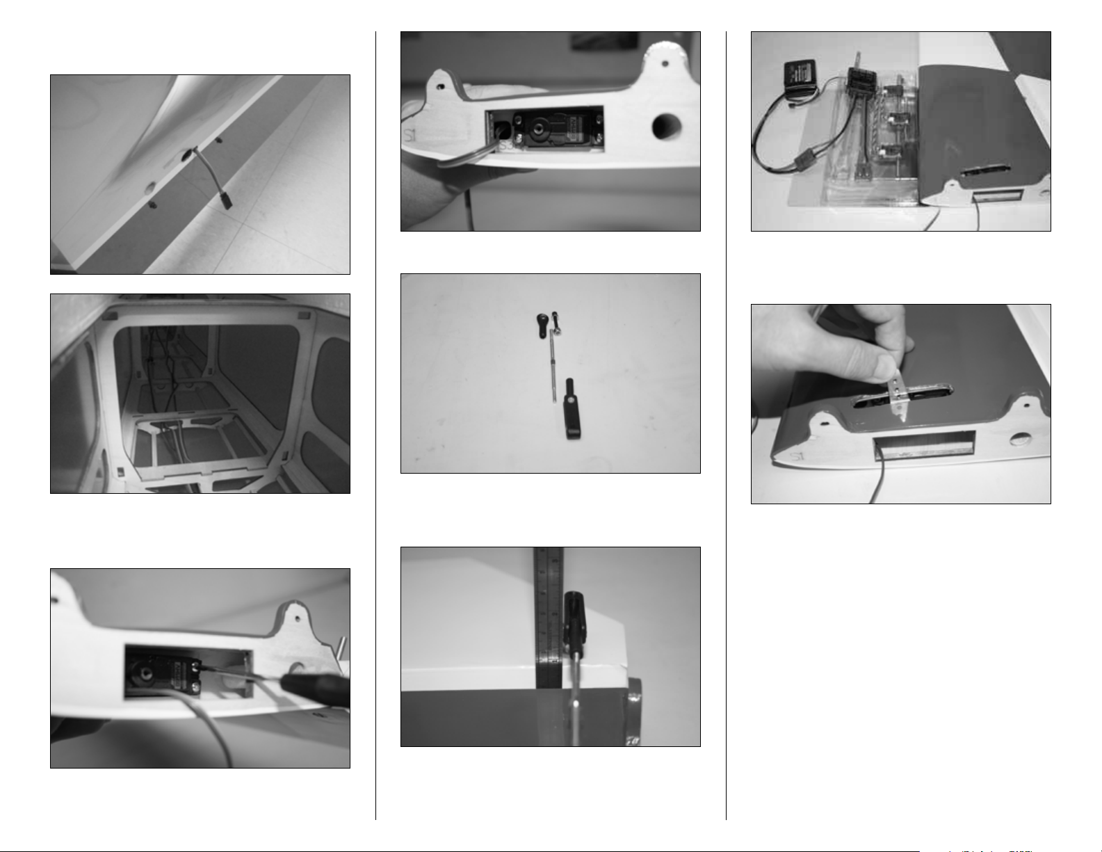
rudder hinge line and mark the mounting lugs.
4. Using a pin vise, drill the marked spots.
2. Apply a piece of masking tape over the knot holding
the leads.
5. Mount the servo screws and back them out, then
1535% Extra 300 ARF Assembly Manual
Page 16

apply some CA to harden the wall. Once CA is dry, mount the
servo.
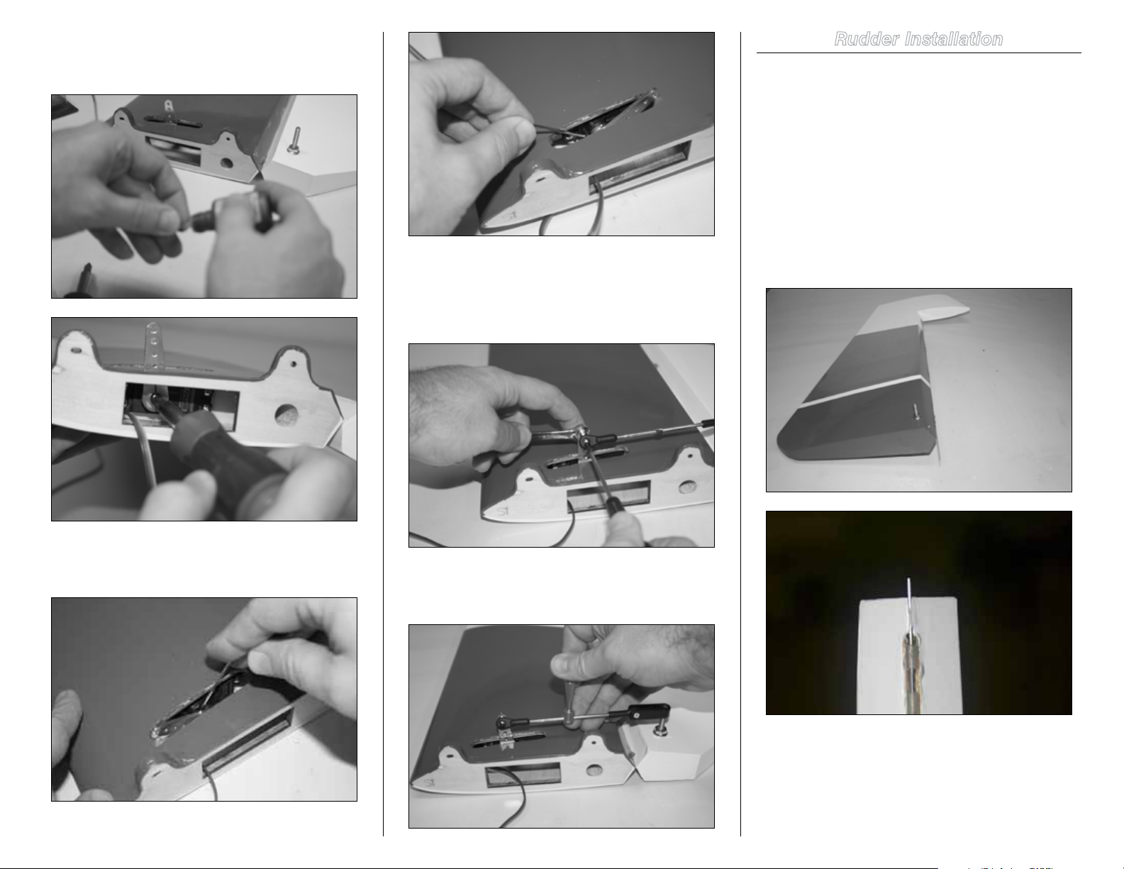
7. Mount the control horn. Adjust the height to 1 7/8 inch
from the rudder hinge line to the center of the pivot point on
the horn.
8. Attach the ball link to 1 1/2-inch servo arm.
10. Apply threadlock to the servo center screw and
mount the servo arm.
11. Mount the servo arm setscrews.
6. Prepare the servo linkage.
12. Using a Hangar 9 Pro-Link Wrench, adjust the length
9. Power up the servo by connecting to the receiver and
with radio sub-trim at 0, mount the arm towards the bottom
of the aircraft and parallel to the hinge line.
16 35% Extra 300 ARF Assembly Manual
of the linkage so when the servo arm is parallel to the rudder
hinge line, rudder is at center.
Page 17

Main Gear and Wheel Pants
Installation
Required Parts
Landing gear 5/32-inch axles (2)
Wheel collars (4) 4mm bolts (4)
Locknuts (4) 4-40 screws (4)
Lock washers (4) Washers (4)
Wheel pants (2) Wheels (2)
Required Tools and Adhesives
3mm ball driver 9mm socket
Crescent wrench 1/2-inch wrench
Threadlock Felt-tipped pen
Thin CA Shoo Goo
3/32-inch ball driver
1. Locate all the hardware necessary to mount the wheels
and wheel pants. Gear is mounted swept forward.
2. Pass the cuffs through the landing gear legs as pictured
below so it fits the contour of the fuselage. Try the cuff and
gear on the fuselage if in doubt about orientation.
3. Install the axle using an 1/2-inch nut wrench and
crescent wrench.
4. Each wheel axle has two flat spots. Install the wheel
using the two wheel collars provided; apply threadlock to the
setscrews and tighten them. The wheel needs to rotate freely
and be centered.
5. Apply threadlock to the wheel pant screws.
1735% Extra 300 ARF Assembly Manual
Page 18

6. Install the wheel pants. The order of installation is:
bolts, lock washers then washers.
8. Once both wheel pants and wheels are assembled,
the gear should look like this.
7. The wheel needs to be in the center of the pant as in
the picture below. If the wheel is rubbing against the wheel
pant, make sure to correct this by loosening the wheel
collars and adjusting the wheel position.
9. To install the landing gear to the fuselage, use a long
3mm ball driver and #9 socket. It is also helpful to have a
magnet to insert the landing gear bolt and washers from the
top of the fuselage into the plate. The picture below shows
the tools needed to install the landing gear.
11. Once the landing gear is secured, pull up the cuffs
until they touch the fuselage and mark the bottom of the
cuffs onto the landing gear with a felt-tipped pen.
10. Use the long 3mm ball driver from the top and
socket from the bottom to tighten the landing gear to the
fuselage.
12. Apply Shoo Goo to and above the marked spots.
18 35% Extra 300 ARF Assembly Manual
Page 19

Engine and Throttle Servo Installation
Required Parts
Fuselage Wood plate
Required Parts (not included)
DA-120 Engine DA stock mufflers
JR-537 servo (1)
JR 24-inch servo extension
Required Tools and Adhesives
Threadlock 4.5mm hex wrench
Hobby knife with #11 blade Felt-tipped pen
Pin vise
#1 Phillips screwdriver
Rotary tool with sanding drum
30-minute epoxy
Acid brush Mixing cup
1. Mount the engine using ¼-20 bolts and wood spacers
provided and make sure to apply threadlock to all the bolts.
Opening of wood spacers should face the engine box cutout.
The picture below shows the wood spacers and bolts.
13. Pull the cuffs up and clean the marking and excess
Shoo Goo with alcohol swabs.
2. Prepare the throttle servo by inserting the rubber
grommets and brass eyelets.
The following pictures show engine installation.
3. Attach a 24-inch extension. Secure the leads with
dental floss and apply a piece of masking tape over the
connectors.
1935% Extra 300 ARF Assembly Manual
Page 20

5. To harden the mounting walls in the wood, install the
servo screws and back them out. Then apply thin CA into the
holes. Once CA is dry install the servo. The pictures below
show this process sequentially.
6. Prepare the throttle servo linkage by attaching the ball
links to the ends. Note the ball link should be mounted below
the servo arm as pictured.
7. Slightly enlarge DA throttle arm hole by drilling with
3/32-inch and then 7/64-inch drill bits to accept the 4-40 ball
link.
4. Mount the throttle servo so that the servo output shaft
is closer to the front of the engine. Mark the mounting holes
and drill the holes using a pin vise.
8. Install the throttle linkage to the engine throttle arm.
20 35% Extra 300 ARF Assembly Manual
Page 21

9. Mark where the throttle linkage touches the engine
box.
10. Using a rotary tool and sanding drum, remove some
of the edge of the engine box so the throttle linkage has a
straight shot to the engine throttle arm with no binding.
11. Complete the throttle linkage installation by powering
servo and making adjustments through the radio.
2135% Extra 300 ARF Assembly Manual
Page 22

In-Cowl Mufflers Installation
Required Parts
Fuselage Wood plate
Required Parts (not included)
DA compact mufflers
Required Tools and Adhesives
Threadlock 4mm hex wrench
Rotary tool Sanding drum
Cutting wheel
NOTICE: Always refer to the product’s instructions for
installation, use and safety.
WARNING: This product can become extremely
hot when in use, which could lead to burns.
1. Prepare the DA compact mufflers by inserting the
gasket and bolts in the muffler. Apply threadlock on the bolt.
4. Use a sanding drum to shape the stacks on the cowl.
3. Bottom of the cowl needs to be opened to
accommodate DA compact muffler. Mark how much the cowl
needs to be opened. Using a rotary tool and cutting disk,
open the cowl little by little until reaching correct size.
2. Using a 4 mm ball driver, bolt on the mufflers such
that DA logo is facing the front of the airplane and stacks are
towards the aft of the engine.
5. When using compact mufflers, the canister tunnel
opening can be blocked off by the wood plate provided.
22 35% Extra 300 ARF Assembly Manual
Page 23

6. Mix 30-minute epoxy and glue the wood plate in place
to block the canister tunnel.
Canister Installation
Required Parts
Silicone tubing
Required Parts (not included)
MTW 75 Canister
50mm drop header, 10 1/2-inch header length for MTW
TD75 canister setup
Couplers Clamps
Required Tools and Adhesives
Hobby knife Felt-tipped pen
Clamps Hobby knife
Vise grip Iron
Masking tape Industrial lubricant
Acid brush Mixing cup and sticks
Ruler or caliper Rotary tool
Cutting wheel
1. The model comes with the canister mount already
installed. Remove the covering from the bay behind the
canister mount by applying 4 pieces of masking tape along
the edges of the section that need to be opened for canisters.
Use a hobby knife to remove the covering.
2. Iron down the edges of the tunnel and remove any
excess covering that may catch air in flight.
3. Pass the silicone tubing through the upper middle hole
and go through each hole in the circumference of the mount
from the inside until you are back at the same middle hole
that you started. Cut off the silicone tubing once finished.
Follow the next 3 pictures as reference.
2335% Extra 300 ARF Assembly Manual
Page 24

8. Complete the header/canister assembly as pictured
below.
The picture below shows how the mount looks after
silicone tubing is properly wrapped around the canister
mount.
4. Recommended header length for MTW TD75 canister
and DA-120 is 10 1/2-inches.
6. Insert the header and canister into the coupler. Leave
1/8--1/4-inch gap between header and pipe.
9. Slide the canisters inside the tunnel and into the
mount. Mount the header using blue threadlock and gasket.
7. Slide the clamps over the coupler and canister and
coupler and header. Note that clamp needs to be forward
of the bump on the header to help hold the header in place
from sliding out.
The picture below is of the tail end of the pipe tunnel.
5 Assemble the canister/header using a vice-grip to open
the clamps and slide them over the header.
24 35% Extra 300 ARF Assembly Manual
Page 25

10. Cut and remove the bottom former of the cowl for
canister exits using a rotary tool and cutting wheel.
Tuned Pipe Installation
Required Parts
Pipe mounts Silicone tubing
Required Parts (not included)
MTW RE2 Pipe
50mm drop header, 11 1/2-inch for RE2 tuned pipe setup
Couplers Clamps
Required Tools and Adhesives
Hobby knife Felt-tipped pen
30-minute epoxy Clamps
Vise grip Iron
Ruler 100-grit sandpaper
Masking tape Industrial lubricant
Acid brush Mixing cup and sticks
1. Prepare the mount by passing the silicone tubing
through the holes starting from the middle and finishing in
the middle.
2. Apply 4 pieces of masking tape along the edges of the
section needed to be opened for tuned pipe cooling.
3. Cut along the masking tape and remove the covering.
2535% Extra 300 ARF Assembly Manual
Page 26

7. Trial fit the mount before gluing to the fuselage. If it
needs adjustment use 100-grit sandpaper and adjust for a
snug fit.
4. Remove the balsa ramp.
5. Iron down the edges and make sure to remove any
excess covering that may catch air in-flight and lift up.
9. Apply some epoxy to the fuselage where the mount
interlocks and the walls where the mount touches.
Note: Make sure that the sandpaper is on a flat surface
and carefully remove a small amount until fit is perfect.
Do not over sand the mount.
10. Carefully glue the mount in place and wait until it is
cured before installing the tuned pipes.
The picture below shows the mount installed.
8. Once satisfied with the fit of the mount in the fuselage,
6. Remove the covering from the aft opening. The picture
below shows the two places where covering needs to be
removed for tune pipe installation.
26 35% Extra 300 ARF Assembly Manual
mix a small amount of 30-minute epoxy with mixing cup and
sticks and apply to the mount using acid brush.
Page 27

11. Recommended header length for MTW RE2 tuned
pipe and DA120 is 11 1/2 inches . Assemble the pipe/header
using a vice-grip. Open the clamps and slide them over the
header.
where clamps are using a heat gun at high setting. Do this
for a few minutes and allow some time for cooling. Repeat
this one more time. This creates a good grip and reduces
chance of pipe/header slipping out in flight. It is also
recommended to do this before the first flight. Let engine
idle for 3 to 4 minutes to warm up the couplers, gradually
increasing the throttle to half to get the engine hot and then
allow a cool- down period before the first flight. This should
not need repeating and when done right, header/pipe will not
slip out.
16. Slide the pipes into the tunnel. Use lubricants over
the pipes or the silicone mount for ease of installation.
13. Push the other side of coupler into the RE2 pipe and
leave 1/8–1/4 inch gap between header and pipe.
12. Coupler fit on the header is tight. Use the working
bench to lay one side of the coupler on and exert pressure
from the other side by hand.
17. Apply threadlock to header bolts and use DA gasket
or high-temperature RTV and bolt the headers to the engine.
14. Once satisfied with the gap, pull the clamps on and
over the coupler and pipe. Then slide the other clamp on
the pipe and header, such that is it forward the bump on the
header.
15. Once everything is assembled, heat the couplers
2735% Extra 300 ARF Assembly Manual
Page 28

Picture of the aft end of the tuned pipes in the tunnel.
Receiver and Ignition Battery
Installation
Required Parts
Fuselage Hook and loop roll
Required Parts (not included)
(2) 4000mAh 2-cell Spektrum Li-Po
(1) 2000mAh 2-cell Spektrum Li-Po
Required Tools and Adhesives
Medium CA
Scissors
Adhesive-backed hook and loop
1. Cover the back of the batteries with pieces of
masking tape as in the picture below.
3. Cut 3 pieces of opposite side of the hook and loop that
are glued to the batteries.
4. Using medium CA, glue the pieces of hook and loop to
the fuselage in the allocated battery place.
2. Apply some medium CA to the back of masking
tape and glue a piece of hook and loop to the masking tape.
28 35% Extra 300 ARF Assembly Manual
Page 29

5. Cut 3 pieces of hook and loop from the roll provided
in the kit.
Ignition Module, Switch and Regulator
Installation
Required Parts
Fuselage
Required Parts (not included)
JR 5203 regulator Ignition Module
JR heavy-duty switch or similar
JR heavy-duty 6-inch extension
Required Tools and Adhesives
Medium CA 1/4-inch Du-Bro foam
Scissors
Adhesive-backed hook and loop
1. Apply some pieces of masking tape to the back of the
ignition module.
6. Make sure CA is dry, mount the batteries and strap
them in using the hook and loop. Receiver batteries are
located at the sides and ignition battery in the middle.
3. Glue a piece of hook and loop using medium CA.
2. Apply some medium CA to the back of masking tape
and glue a piece of foam to the masking tape.
4. Apply some medium CA to the engine box where the
ignition module will be glued.
2935% Extra 300 ARF Assembly Manual
Page 30

5. Cut the opposite side of hook and loop to the ignition
module and glue to the engine box.
6. Cut a piece from the hook and loop roll provided in the
kit and strap the ignition module in place.
8. Glue a piece of industrial-strength hook and loop using
medium CA to the back of the regulator over the masking
tape.
10. Mount the regulator.
11. Ignition switch mount is already installed at the side
of the fuselage. Remove the covering where the ignition
9. Apply some medium CA to the former where the
7. Apply a piece of masking tape to the bottom of the
ignition regulator.
30 35% Extra 300 ARF Assembly Manual
ignition regulator will be mounted and glue the opposite side
of the hook and loop.
switch will be mounted.
Page 31

12. Mount the ignition switch.
Fuel Tank, Fill and Over Flow
Installation
Required Parts
Fuselage Fuel tank
Required Parts (not included)
Hangar 9 Fuel filler and T
Required Tools and Adhesives
Drill and bits (1/16-inch, 1/8-inch, 1/4-inch)
Zip tie
Double-sided tape
Medium CA
Rotary tool
Sanding Drum (3/8-inch)
1/2-inch socket
1. Fuel tank comes assembled and installed. It is
recommended that lines be checked every 2–3 months
and replaced if they have hardened.
2. Fill line is installed at the front left side of the
fuselage using Hangar 9 fuel filler. Drill a small hole; then
using a rotary tool and 3/8-inch diameter sanding drum
or grinding bit, open the side of the fuselage for the fuel
filler.
Using a rotary tool and the sanding drum, open up the
hole. Base of the sanding drum is same size of the fuel
filler housing diameter.
Note: Connect battery to switch, output of the switch
to regulator (6-inch extension is needed) and regulator
output to ignition. With this method, you can charge the
battery directly through the switch charge port.
The picture below shows the sanding drum next to the
fuel filter housing.
3. Apply some threadlock over the threads of the fuel
filler housing and use a 1/2-inch socket to tighten the nut
from inside the fuselage.
3135% Extra 300 ARF Assembly Manual
Page 32

Note: Looping the vent line behind the tank will prevent
gas from siphoning through the vent line in flights and
will increase flight time.
7. The fill line connects to the T-fitting in the fuel line.
4. Drill a 1/8-inch hole in the bottom left side of the
engine box. Then increase the hole by drilling a 1/4-inch
hole. Do not use the 1/4-inch drill bit without doing a smaller
hole or the wood can be cracked.
6. Using commercially available cord clips, route the vent
through the bottom of the engine box.
5. Loop the vent line behind the tank then forward and
through the hole in the bottom of the motor box.
32 35% Extra 300 ARF Assembly Manual
Page 33

Cowl Mounting
Pilot Installation
Required Parts
Cowl Fuselage
(6) 4-40 screws, washers and lock washers
Required Tools and Adhesives
3/32-inch ball driver
1. The cowl is secured at the top and the bottom. There
are four 4-40 screws inserted through the inside of the
fuselage. First the lock washer goes on the screw then the
flat washer.
2. The bottom two 4-40 screws are inserted through the
lower sides of the cowl.
Required Parts
Canopy Pilot
Required Tools and Adhesives
3/32-inch ball driver
Threadlock
Alcohol swab
Shoo Goo
1. Take the screws that hold the pilot head to the body
out and apply threadlock to them and re-tighten.
2. Lightly sand the underside of the shoulders to scuff
the paint and clean the mounting shoulders of the pilot with
alcohol swabs.
3335% Extra 300 ARF Assembly Manual
Page 34

3. Apply Shoo Goo to the underside of the shoulders and
the rear rail of the canopy.
5. The model comes with instrument panels. Cut the
instrument panel decals to size and install on the front and
rear dash boards in the cockpit.
Receiver, Switch and Throttle Servo
Regulator Installation
Required Parts
Fuselage
Required Parts (not included)
JR 5203 regulator AR9110 Receiver
Required Tools and Adhesives
Masking tape Medium CA
CA accelerator
Du-Bro 1/4-inch foam Hook and loop
JR servo extension, 3-inch
1. Prepare the receiver to mount on the tray, similar to
the ignition battery preparation in the previous section. Put
two pieces of masking tape at the bottom of the receiver.
Using CA glue 1/4-inch Du-Bro foam to the masking tape
and glue a piece of hook and loop to the foam.
The picture below shows the front pilot panel.
4. Mount the pilot. Apply some pressure and let the
canopy sit on a flat surface until Shoo Goo cures.
34 35% Extra 300 ARF Assembly Manual
Page 35

2. Glue opposite side of the hook and loop to the tray.
6. Throttle servo regulator is mounted next to the receiver
using two pieces of hook and loop similar to receiver
installation except it does not need foam.
3. Mount the receiver and secure it with a piece of hook
and loop strap.
4. Remove the covering to mount the soft switch. There
are 3 different size switch mounts on each side of the
fuselage.
5. Apply a drop of threadlock on the switch mounting
screws and mount the switch.
7. Run a 24-inch servo extension from throttle servo to
the regulator and a 3-inch extension from the regulator to
the receiver unit.
3535% Extra 300 ARF Assembly Manual
Page 36

Satellite Receiver Installation
Required Parts
Fuselage
Required Parts (not included)
(3 to 4) Satellite receivers
Required Tools and Adhesives
Double-sided tape Masking tape
Hook and loop
Medium CA
Note: It is best to use 4 satellite receivers as this is
a large model. However, with proper placement of
the satellite receivers, 3 would be adequate. A Flight
Log can help with correct placement of the satellite
receivers. Check the health of the system before first
flight.
1. There are two ways to mount the satellite receivers.
One way is to simply apply a piece of double-sided/
servo tape to the back of the satellite receiver and attach
to the fuselage. See step 3 for the alternative method.
Location of Satellite receiver 1.
Location of Satellite receiver 4 - front of the tank and on
the right vertical side.
Location of Satellite receiver 2 - side of the fuselage
tunnel.
Location of Satellite receiver3 - front of the tank and on
the left vertical side.
36 35% Extra 300 ARF Assembly Manual
2. Attach a piece of masking tape to the back of the
satellite receiver; apply a couple of drops of CA to the
masking tape and stick a piece of hook and loop to the
masking tape. Note that even if the hook and loop is
adhesive-backed, CA helps hold the hook and loop to the
masking tape in high temperatures.
Page 37

slight coupling in knife edge.
Please note this is very CG dependant.
Elevator:
High Rate: Expo
Up: 50 degrees 70%
Down: 50 degrees 70%
Normal: Expo
Up: 12 degrees 40%
Down: 11 degrees 40%
Center of Gravity
An important part of preparing the aircraft for flight is
properly balancing the model.
CAUTION: Do not inadvertently skip this step!
The recommended Center of Gravity (CG) location for your
model is 4 inches to 4 3/4 inches (10.2cm 12cm) to back
from the leading edge of the wing tip as shown. Mark the
location of the CG on the top of the wing with a felt-tipped
pen.
Use help to lift the plane from the marked position.
For precision and IMAC flying, 4 inches (10.2cm) is the
best CG. For the best combination of strong 3D flying and
a more sensitive yet precise feel, 4-3/4 inches (12.7cm) is
recommended.
After the first flights, the CG position can be adjusted for
your personal preference.
Control Throws
1. Turn on the transmitter and receiver of your model.
Check the movement of the rudder using the transmitter.
When the stick is moved right, the rudder should also move
right. Reverse the direction of the servo at the transmitter if
necessary.
2. Check the movement of the elevator with the radio
system. Moving the elevator stick toward the bottom of the
transmitter will make the airplane elevator move up.
3. Check the movement of the ailerons with the radio
system. Moving the aileron stick right will make the right
aileron move up and the left aileron move down.
4. Use a throw meter to adjust the throw of the elevator,
ailerons and rudder.
Mike McConville has three flight modes as follows:
1. Normal: This flight mode is used for most precision
maneuvers.
2. Fast Roll: This flight mode is for aggressive yet precise
aerobatics such as very fast rolling loops, hammers, or
maneuvers needing strong knife edge. It has high-rate
aileron and rudder and low-rate elevator.
3. High (3D): All surfaces at full deflection for 3D flying.
Aileron:
High Rate: Expo
Up: 40 degrees 50%
Down: 40 degrees 50%
Normal Rate: Expo
Up: 24 degrees 35%
Down: 24 degrees 35%
Rudder:
High: Expo
Right: 45 degrees 45%
Left: 45 degrees 45%
Normal Rate:
Right: 27 degrees 40%
Left: 27 degrees 40%
These are general guidelines measured from our own flight
tests. You can experiment with different rates to match your
preferred style of flying.
If using the Spektrum DX-8, Mike’s personal setup can
be downloaded from the Spektrum Community website
at: https://community.spektrumrc.com/.
Mike’s Extra 300 is balanced at the 4-3/4” CG location.
His setup uses a slight down elevator to throttle mix at very
low throttle stick position for down lines. 6% up elevator to
rudder and 3% opposite aileron to rudder mixing to eliminate
3735% Extra 300 ARF Assembly Manual
Page 38

Applying Decals
The model comes with decal sets and all decals are die-cut. All large decals should be applied wet so the bubbles can be worked out by squeegee. Allow 24 hours for decals to dry and
adhesive to set.
It is important to take all the wrinkles in the covering out and would be best to apply the decals after the plane has been taken to a flying field a couple of times and all the wrinkles have
been removed. The following pictures show the location of decals.
38 35% Extra 300 ARF Assembly Manual
Page 39

Preight
Safety Do’s and Don’ts for Pilots
Check Your Radio
Before going to the field, be sure your batteries are
fully charged per your radio’s instructions. Charge the
transmitter and motor battery for your airplane. Use the
recommended charger supplied with your particular radio
system, following the instructions provided with the radio.
In most cases, the radio should be charged the night before
going out flying.
Before each flying session, be sure to range check your
radio. See your radio manual for the recommended
range and instructions for your radio system. Each radio
manufacturer specifies different procedures for their radio
systems. Next, run the motor. With the model securely
anchored, check the range again. The range test should not
be significantly affected. If it is, don’t attempt to fly! Have
your radio equipment checked out by the manufacturer.
Double-check that all controls (aileron, elevator, rudder and
throttle) move in the correct direction.
Check the radio installation and make sure all the control
surfaces are moving correctly (i.e., the correct direction and
with the recommended throws).
Check all the control horns, servo horns, and clevises to
make sure they are secure and in good condition.
Range Test Your Radio
Before each flying session, and especially with a new model,
it is important to perform a range check. It is helpful to have
another person available to assist during the range check. If
you are using a Spektrum transmitter, please refer to your
transmitter’s manual for detailed instructions on the range
check process.
• Checkallcontrolsurfacespriortoeachtakeoff.
• Donotflyyourmodelnearspectators,parkingareasor
any other area that could result in injury to people or
damage of property.
• Donotflyduringadverseweatherconditions.Poor
visibility can cause disorientation and loss of control of
your aircraft. Strong winds can cause similar problems.
• Donottakechances.Ifatanytimeduringflight
you observe any erratic or abnormal operation, land
immediately and do not resume flight until the cause of
the problem has been ascertained and corrected. Safety
can never be taken lightly.
• Donotflynearpowerlines.
Daily Flight Checks
• 1.Checkthebatteryvoltageofthetransmitterbattery.
Do not fly below the manufacturer’s recommended
voltage. To do so can crash your aircraft.
When you check these batteries, ensure you have the
polarities correct on your expanded scale voltmeter.
• 2.Checkallhardware(linkages,screws,nuts,andbolts)
prior to each day’s flight. Be sure that binding does not
occur and that all parts are properly secured.
• 3.Ensureallsurfacesaremovinginthe
proper manner.
• 4.Performagroundrangecheckbeforeeachday’s
flying session.
• 5.Priortostartingyouraircraft,turnoffyour
transmitter, then turn it back on. Do this each time you
start your aircraft. If any critical switches are on without
your knowledge, the transmitter alarm will sound a
warning at this time.
• 6.Checkthatalltrimleversareintheproperlocation.
• 7.Allservopigtailsandswitchharnessplugsshouldbe
secured in the receiver. Make sure the switch harness
moves freely in both directions.
3935% Extra 300 ARF Assembly Manual
Page 40

LIMITED WARRANTY
WHAT THIS WARRANTY COVERS
Horizon Hobby, Inc. (“Horizon”) warrants to the original
purchaser that the product purchased (the “Product”) will be
free from defects in materials and workmanship at the date
of purchase.
WHAT IS NOT COVERED
This warranty is not transferable and does not cover (i)
cosmetic damage, (ii) damage due to acts of God, accident,
misuse, abuse, negligence, commercial use, or due to
improper use, installation, operation or maintenance, (iii)
modification of or to any part of the Product, (iv) attempted
service by anyone other than a Horizon Hobby authorized
service center, or (v) Products not purchased from an
authorized Horizon dealer.
OTHER THAN THE EXPRESS WARRANTY ABOVE, HORIZON
MAKES NO OTHER WARRANTY OR REPRESENTATION, AND
HEREBY DISCLAIMS ANY AND ALL IMPLIED WARRANTIES,
INCLUDING, WITHOUT LIMITATION, THE IMPLIED
WARRANTIES OF NON-INFRINGEMENT, MERCHANTABILITY
AND FITNESS FOR A PARTICULAR PURPOSE. THE
PURCHASER ACKNOWLEDGES THAT THEY ALONE HAVE
DETERMINED THAT THE PRODUCT WILL SUITABLY MEET
THE REQUIREMENTS OF THE PURCHASER’S INTENDED
USE.
PURCHASER’S REMEDY
Horizon’s sole obligation and purchaser’s sole and exclusive
remedy shall be that Horizon will, at its option, either (i)
service, or (ii) replace, any Product determined by Horizon
to be defective. Horizon reserves the right to inspect any
and all Product(s) involved in a warranty claim. Service or
replacement decisions are at the sole discretion of Horizon.
Proof of purchase is required for all warranty claims.
SERVICE OR REPLACEMENT AS PROVIDED UNDER THIS
WARRANTY IS THE PURCHASER’S SOLE AND EXCLUSIVE
REMEDY.
LIMITATION OF LIABILITY
HORIZON SHALL NOT BE LIABLE FOR SPECIAL, INDIRECT,
INCIDENTAL OR CONSEQUENTIAL DAMAGES, LOSS OF
PROFITS OR PRODUCTION OR COMMERCIAL LOSS IN ANY
40 35% Extra 300 ARF Assembly Manual
WAY, REGARDLESS OF WHETHER SUCH CLAIM IS BASED
IN CONTRACT, WARRANTY, TORT, NEGLIGENCE, STRICT
LIABILITY OR ANY OTHER THEORY OF LIABILITY, EVEN
IF HORIZON HAS BEEN ADVISED OF THE POSSIBILITY OF
SUCH DAMAGES. Further, in no event shall the liability of
Horizon exceed the individual price of the Product on which
liability is asserted. As Horizon has no control over use,
setup, final assembly, modification or misuse, no liability
shall be assumed nor accepted for any resulting damage or
injury. By the act of use, setup or assembly, the user accepts
all resulting liability. If you as the purchaser or user are
not prepared to accept the liability associated with the use
of the Product, purchaser is advised to return the Product
immediately in new and unused condition to the place of
purchase.
LAW
These terms are governed by Illinois law (without regard to
conflict of law principals). This warranty gives you specific
legal rights, and you may also have other rights which vary
from state to state. Horizon reserves the right to change or
modify this warranty at any time without notice.
WARRANTY SERVICES
Questions, Assistance, and Services
Your local hobby store and/or place of purchase cannot
provide warranty support or service. Once assembly, setup
or use of the Product has been started, you must contact
Horizon directly. This will enable Horizon to better answer
your questions and service you in the event that you may
need any assistance. For questions or assistance, please
direct your email to productsupport@horizonhobby.com, or
call 877.504.0233 toll free to speak to a Product Support
representative. You may also find information on our website
at www.horizonhobby.com.
INSPECTION OR SERVICES
If this Product needs to be inspected or serviced, please
use the Horizon Online Service Request submission process
found on our website or call Horizon to obtain a Return
Merchandise Authorization (RMA) number. Pack the Product
securely using a shipping carton. Please note that original
boxes may be included, but are not designed to withstand
the rigors of shipping without additional protection. Ship
via a carrier that provides tracking and insurance for lost
or damaged parcels, as Horizon is not responsible for
merchandise until it arrives and is accepted at our facility.
An Online Service Request is available at http://www.
horizonhobby.com under the Support tab. If you do not have
internet access, please contact Horizon Product Support to
obtain a RMA number along with instructions for submitting
your product for service. When calling Horizon, you will be
asked to provide your complete name, street address, email
address and phone number where you can be reached during
business hours. When sending product into Horizon, please
include your RMA number, a list of the included items, and a
brief summary of the problem. A copy of your original sales
receipt must be included for warranty consideration. Be sure
your name, address, and RMA number are clearly written on
the outside of the shipping carton.
Notice: Do not ship LiPo batteries to Horizon. If you
have any issue with a LiPo battery, please contact the
appropriate Horizon Product Support office.
WARRANTY REQUIREMENTS
For Warranty consideration, you must include your
original sales receipt verifying the proof-of-purchase date.
Provided warranty conditions have been met, your Product
will be serviced or replaced free of charge. Service or
replacement decisions are at the sole discretion of Horizon.
NON-WARRANTY SERVICE
Should your service not be covered by warranty service
will be completed and payment will be required without
notification or estimate of the expense unless the expense
exceeds 50% of the retail purchase cost. By submitting
the item for service you are agreeing to payment of the
service without notification. Service estimates are available
upon request. You must include this request with your item
submitted for service. Non-warranty service estimates will
be billed a minimum of ½ hour of labor. In addition you will
be billed for return freight. Horizon accepts money orders
and cashiers checks, as well as Visa, MasterCard, American
Express, and Discover cards. By submitting any item to
Horizon for service, you are agreeing to Horizon’s Terms and
Conditions found on our website http://www.horizonhobby.
com/Service/Request/.
Page 41

United States:
Electronics and engines requiring inspection or repair
should be shipped to the following address:
Horizon Service Center
4105 Fieldstone Road
Champaign, Illinois 61822
USA
Online Repair Request visit:
www.horizonhobby.com/repairs
All other Products requiring warranty inspection or repair
should be shipped to the following address:
Horizon Product Support
4105 Fieldstone Road
Champaign, Illinois 61822
USA
Please call 877-504-0233 or e-mail us at productsupport@
horizonhobby.com with any questions or concerns regarding
this product or warranty.
United Kingdom:
Electronics and engines requiring inspection or repair
should be shipped to the following address:
Horizon Hobby Limited
Units 1-4 Ployters Rd
Staple Tye
Harlow, Essex
CM18 7NS
United Kingdom
Please call +44 (0) 1279 641 097 or e-mail us at sales@
horizonhobby.co.uk with any questions or concerns
regarding this product or warranty.
Germany:
Electronics and engines requiring inspection or repair
should be shipped to the following address:
Horizon Technischer Service
Hamburger Strasse 10
25335 Elmshorn
Germany
Compliance Information for the
European Union
INSTRUCTIONS FOR DISPOSAL OF WEEE BY
USERS IN THE EUROPEAN UNION
This product must not be disposed of with other waste.
Instead, it is the user’s responsibility to dispose of their
waste equipment by handing it over to a designated
collection point for the recycling of waste electrical and
electronic equipment. The separate collection and recycling
of your waste equipment at the time of disposal will help to
conserve natural resources and ensure that it is recycled in
a manner that protects human health and the environment.
For more information about where you can drop off your
waste equipment for recycling, please contact your local city
office, your household waste disposal service or where you
purchased the product.
Please call +49 4121 46199 66 or e-mail us at service@
horizonhobby.de with any questions or concerns regarding
this product or warranty.
France:
Horizon Hobby SAS
14 Rue Gustave Eiffel
Zone d’Activité du
Réveil Matin
91230 Montgeron
Please call +33 (0) 1 60 47 44 70 with any questions or
concerns regarding this product or warranty.
infofrance@horizonhobby.com
4135% Extra 300 ARF Assembly Manual
Page 42

2011 Official Academy of Model
Aeronautics Safety Code
Effective January 1, 2011
A. GENERAL: A model aircraft is a non-human-carrying
aircraft capable of sustained flight in the atmosphere. It may
not exceed limitations of this code and is
intended exclusively for sport, recreation and/or competition.
All model flights must be conducted in accordance with this
safety code and any additional
rules specific to the flying site.
1. Model aircraft will not be flown:
(a) In a careless or reckless manner.
(b) At a location where model aircraft activities are
prohibited.
2. Model aircraft pilots will:
(a) Yield the right of way to all man carrying aircraft.
(b) See and avoid all aircraft and a spotter must be used
when appropriate. (AMA Document #540-D-See and Avoid
Guidance.)
(c) Not fly higher than approximately 400 feet above ground
level within three (3) miles of an airport, without notifying
the airport operator.
(d) Not interfere with operations and traffic patterns at any
airport, heliport or seaplane base except where there is a
mixed use agreement.
(e) Not exceed a takeoff weight, including fuel, of 55 pounds
unless in compliance with the AMA Large Model Aircraft
program. (AMA Document 520-A)
(f) Ensure the aircraft is identified with the name and address
or AMA number of the owner on the inside or affixed to the
outside of the model aircraft.
(This does not apply to model aircraft flown indoors).
(g) Not operate aircraft with metal-blade propellers or with
gaseous boosts except for helicopters operated under the
provisions of AMA Document #555.
(h) Not operate model aircraft while under the influence of
alcohol or while using any drug which could adversely affect
the pilot’s ability to safely control
the model.
(i) Not operate model aircraft carrying pyrotechnic devices
which explode or burn, or any device which propels a
projectile or drops any object that
42 35% Extra 300 ARF Assembly Manual
creates a hazard to persons or property.
Exceptions:
Free Flight fuses or devices that burn producing smoke
and are securely attached to the model aircraft during flight.
Rocket motors (using solid propellant) up to a G-series
size may be used provided they remain attached to the
model during flight. Model rockets
may be flown in accordance with the National Model
Rocketry Safety Code but may not be launched from model
aircraft.
Officially designated AMA Air Show Teams (AST) are
authorized to use devices and practices as defined within the
Team AMA Program
Document (AMA Document #718).
(j) Not operate a turbine-powered aircraft, unless in
compliance with the AMA turbine regulations. (AMA
Document #510-A).
3. Model aircraft will not be flown in AMA sanctioned events,
air shows or model demonstrations unless:
(a) The aircraft, control system and pilot skills have
successfully demonstrated all maneuvers intended or
anticipated prior to the specific event.
(b) An inexperienced pilot is assisted by an experienced pilot.
4. When and where required by rule, helmets must be
properly worn and fastened. They must be OSHA, DOT, ANSI,
SNELL or NOCSAE approved or
comply with comparable standards.
B. RADIO CONTROL (RC)
1. All pilots shall avoid flying directly over unprotected
people, vessels, vehicles or structures and shall avoid t.
2. A successful radio equipment ground-range check in
accordance with manufacturer’s recommendations will be
completed before the first flight of a new or
repaired model aircraft.
3. At all flying sites a safety line(s) must be established
in front of which all flying takes place (AMA Document
#706-Recommended Field Layout):
(a) Only personnel associated with flying the model aircraft
are allowed at or in front of the safety line.
(b) At air shows or demonstrations, a straight safety line
must be established.
(c) An area away from the safety line must be maintained for
spectators.
(d) Intentional flying behind the safety line is prohibited.
4. RC model aircraft must use the radio-control frequencies
currently allowed by the Federal Communications
Commission (FCC). Only individuals properly
licensed by the FCC are authorized to operate equipment on
Amateur Band frequencies.
5. RC model aircraft will not operate within three (3) miles of
any pre-existing flying site without a frequency-management
agreement (AMA Documents #922-
Testing for RF Interference; #923- Frequency Management
Agreement)
6. With the exception of events flown under official AMA
Competition Regulations, excluding takeoff and landing, no
powered model may be flown outdoors
closer than 25 feet to any individual, except for the pilot and
the pilot’s helper(s) located at the flight line.
7. Under no circumstances may a pilot or other person touch
a model aircraft in flight while it is still under power, except
to divert it from striking an individual.
This does not apply to model aircraft flown indoors.
8. RC night flying requires a lighting system providing the
pilot with a clear view of the model’s attitude and orientation
at all times.
9. The pilot of a RC model aircraft shall:
(a) Maintain control during the entire flight, maintaining
visual contact without enhancement other than by corrective
lenses prescribed for the pilot.
(b) Fly using the assistance of a camera or First-Person View
(FPV) only in accordance with the procedures outlined in
AMA Document #550.
C. FREE FLIGHT
1. Must be at least 100 feet downwind of spectators and
automobile parking when the model aircraft is launched.
2. Launch area must be clear of all individuals except
mechanics, officials, and other fliers.
3. An effective device will be used to extinguish any fuse on
the model aircraft after the fuse has completed its function.
D. CONTROL LINE
1. The complete control system (including the safety thong
where applicable) must have an inspection and pull test prior
to flying.
2. The pull test will be in accordance with the current
Competition Regulations for the applicable model aircraft
category.
Page 43

3. Model aircraft not fitting a specific category shall use
those pull-test requirements as indicated for Control Line
Precision Aerobatics.
4. The flying area must be clear of all utility wires or poles
and a model aircraft will not be flown closer than 50 feet to
any above-ground electric utility lines.
5. The flying area must be clear of all nonessential
participants and spectators before the engine is started.
4335% Extra 300 ARF Assembly Manual
Page 44

Hangar 9, UltraCote and MatchBox are trademarks or registered trademarks of Horizon Hobby, Inc.
JR is a trademark of Horizon Hobby, Inc., registered in the U.S.
The Spektrum trademark is used with permission of Bachmann Industries, Inc.
28991
© 2011 Horizon Hobby, Inc.
horizonhobby.com
Hangar9.com
Printed 03/2011
 Loading...