

Hangar 9 Edge 540 Assembly Manual
ASSEMBLY MANUAL
Specifications
Wingspan: .............. 97.5 in (2476.5mm)
Length: ................... 85 in (2159mm)
Wing Area: ............ 1730.6 sq in (111.65 sq dm)
Weight:................... 22.5–25.5 lb (10.2 kg–11.5 kg)
Radio: ..................... 4-channel w/8 servos
Engines: ................... 3.8–4.8 cu in
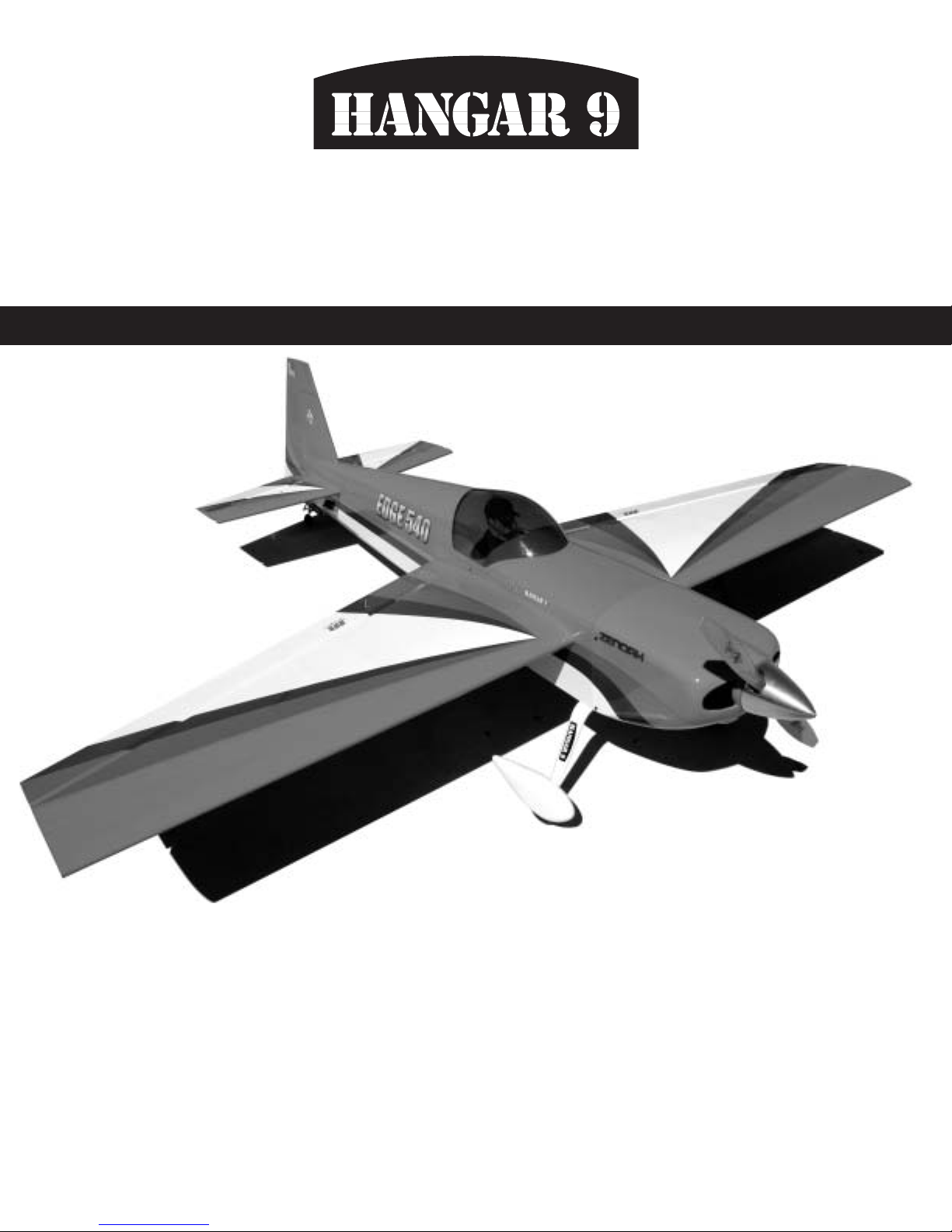
Edge 540
TM
• Superior controllability and aerobatic flight characteristics
• Lightweight construction
• Designed by veteran TOC competitor Mike McConville
• 90% built 1/3-scale ARF
• Plug-in wings and stabilizers for easy transport and field assembly
®
WE GET PEOPLE FLYING

2
Table of Contents
Using the Manual . . . . . . . . . . . . . . . . . . . . . . . . . . . . . . . . . . . . . . . . . . . . . . . . . . . . . . . . . . . . . . 2
Table of Contents . . . . . . . . . . . . . . . . . . . . . . . . . . . . . . . . . . . . . . . . . . . . . . . . . . . . . . . . . . . . . . 2
Other Items Needed (not included in the kit) . . . . . . . . . . . . . . . . . . . . . . . . . . . . . . . . . . . . . . . . . . 3
Additional Required Equipment . . . . . . . . . . . . . . . . . . . . . . . . . . . . . . . . . . . . . . . . . . . . . . . . . . . . 3
Contents of Kit . . . . . . . . . . . . . . . . . . . . . . . . . . . . . . . . . . . . . . . . . . . . . . . . . . . . . . . . . . . . . . . . 3
Additional Required Tools and Adhesives . . . . . . . . . . . . . . . . . . . . . . . . . . . . . . . . . . . . . . . . . . . . . 4
Servo Selection . . . . . . . . . . . . . . . . . . . . . . . . . . . . . . . . . . . . . . . . . . . . . . . . . . . . . . . . . . . . . . . . 5
Warning . . . . . . . . . . . . . . . . . . . . . . . . . . . . . . . . . . . . . . . . . . . . . . . . . . . . . . . . . . . . . . . . . . . . . 5
Warranty Information . . . . . . . . . . . . . . . . . . . . . . . . . . . . . . . . . . . . . . . . . . . . . . . . . . . . . . . . . . . . 5
Before Starting Assembly . . . . . . . . . . . . . . . . . . . . . . . . . . . . . . . . . . . . . . . . . . . . . . . . . . . . . . . . 5
Section 1 – Aileron Servo Installation . . . . . . . . . . . . . . . . . . . . . . . . . . . . . . . . . . . . . . . . . . . . . . . 6
Section 2 – Aileron Control Horn Installation . . . . . . . . . . . . . . . . . . . . . . . . . . . . . . . . . . . . . . . . . . 8
Section 3 – Hinging and Sealing the Control Surfaces . . . . . . . . . . . . . . . . . . . . . . . . . . . . . . . . . . 10
Section 4 – Sealing the Hinge Gaps . . . . . . . . . . . . . . . . . . . . . . . . . . . . . . . . . . . . . . . . . . . . . . . 12
Section 5 – Aileron Linkage Installation . . . . . . . . . . . . . . . . . . . . . . . . . . . . . . . . . . . . . . . . . . . . . 14
Section 6 – Wing Installation . . . . . . . . . . . . . . . . . . . . . . . . . . . . . . . . . . . . . . . . . . . . . . . . . . . . 16
Section 7 – Elevator Construction . . . . . . . . . . . . . . . . . . . . . . . . . . . . . . . . . . . . . . . . . . . . . . . . . 17
Section 8 – Rudder Construction . . . . . . . . . . . . . . . . . . . . . . . . . . . . . . . . . . . . . . . . . . . . . . . . . . 21
Section 9 – Landing Gear Installation . . . . . . . . . . . . . . . . . . . . . . . . . . . . . . . . . . . . . . . . . . . . . . 22
Section 10 – Wheel Pant Installation . . . . . . . . . . . . . . . . . . . . . . . . . . . . . . . . . . . . . . . . . . . . . . . 23
Section 11 – Tail Wheel Installation . . . . . . . . . . . . . . . . . . . . . . . . . . . . . . . . . . . . . . . . . . . . . . . . 25
Section 12 – Receiver, Battery and Fuel Tank Installation . . . . . . . . . . . . . . . . . . . . . . . . . . . . . . . . 26
Section 13 – Mounting the Engine and Cowl . . . . . . . . . . . . . . . . . . . . . . . . . . . . . . . . . . . . . . . . . 27
Section 14 – Hatch Assembly . . . . . . . . . . . . . . . . . . . . . . . . . . . . . . . . . . . . . . . . . . . . . . . . . . . . 30
Section 15 – Balancing the Model . . . . . . . . . . . . . . . . . . . . . . . . . . . . . . . . . . . . . . . . . . . . . . . . . 31
Section 17 – Control Throws . . . . . . . . . . . . . . . . . . . . . . . . . . . . . . . . . . . . . . . . . . . . . . . . . . . . . 32
Section 16 – Radio Setup . . . . . . . . . . . . . . . . . . . . . . . . . . . . . . . . . . . . . . . . . . . . . . . . . . . . . . . 32
Preflight at the Field . . . . . . . . . . . . . . . . . . . . . . . . . . . . . . . . . . . . . . . . . . . . . . . . . . . . . . . . . . . 33
2004 Official AMA National Model Aircraft Safety Code . . . . . . . . . . . . . . . . . . . . . . . . . . . . . . . . . 34
Using the Manual
This manual is divided into sections to help make assembly easier to understand and to provide breaks between
each major section. Remember to take your time and follow the directions.
Covering Colors
• Flame Red HANU883 • Pearl Blue HANU845
• Silver HANU881 • White HANU870
3
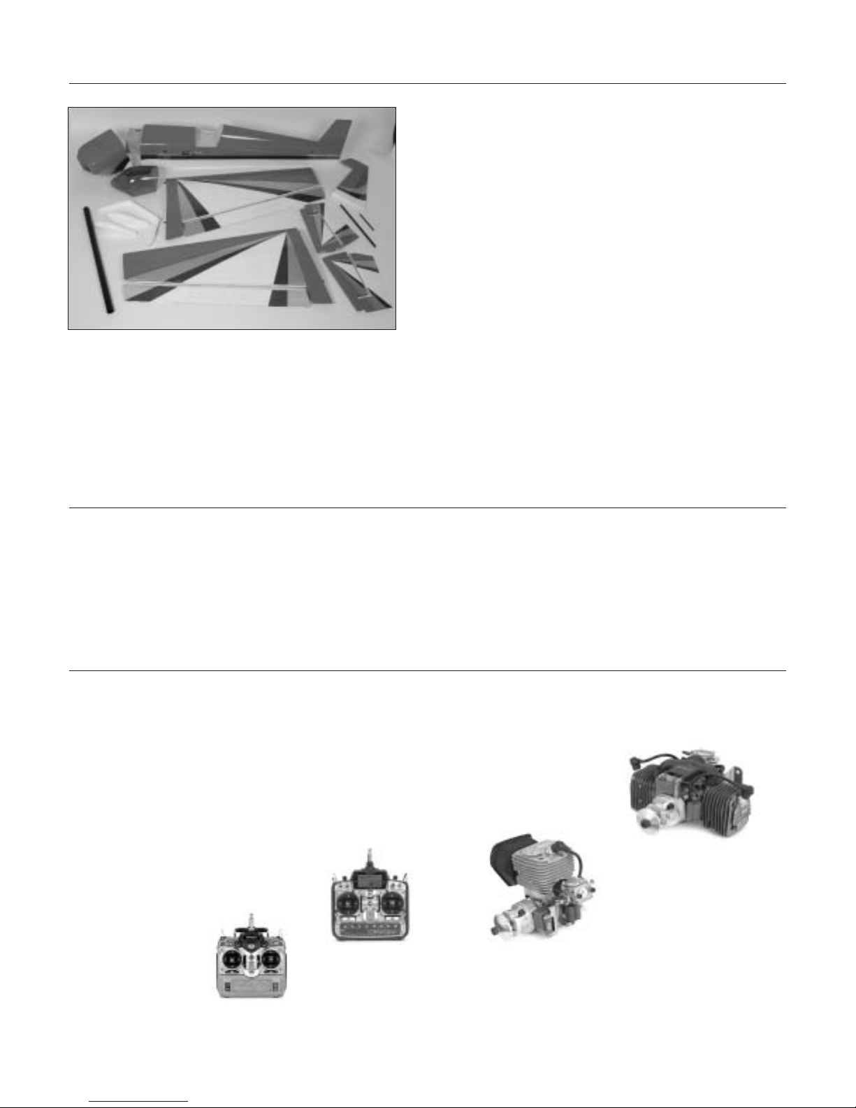
Contents of Kit
Large Parts
A. Fuselage w/Hatch HAN1151
B. Canopy Hatch HAN1158
C. Right Wing Panel w/Aileron HAN1152
D. Left Wing Panel w/Aileron HAN1153
E. Right Stabilizer w/Elevator HAN1154
F. Left Stabilizer w/Elevator HAN1155
G. Rudder HAN1156
H. Canopy HAN1157
I. Painted Cowl HAN1159
J. Carbon Fiber Landing Gear HAN1160
K. Wheel Pants HAN1161
L. Anodized Wing Tube HAN1164
Additional Required Equipment
Radio Equipment
• 6-channel radio system (minimum)
• 1 standard servo for throttle (JRPS537
recommended or equivalent)
• 7 hi-torque servos (JRPS8411
recommended or equivalent)
• 1 hi-torque servo (JRPS8611
recommended or equivalent)
Recommended JR
®
Systems
• PCM10X
• XP8103
• X-378
• XP662
• XF631
Recommended Engines
•G-62, GT-80
JR XP8103
JR PCM 10X
Zenoah®GT-80
ZENE80T
Zenoah®G62
ZENE62A
A
D
C
E
F
Other Items Needed (not included in the kit)
• Propeller (consult engine instructions)
• 12" Servo Extension (JRPA098)
• 18" Servo Extensions (JRPA099) (3)
• 24" Servo Extensions (JRPA102) (5)
• Y-Harness (JRPA133) (2)
• MatchBox™ (JRPA900) (2)
• Zenoah
®
2" Prop Drive (ZEN20004)(GT-80 only)
G
H
I
J
Items not shown:
Landing Gear Fairing HAN1162
Decal Set HAN1163
Anodized Stabilizer Tubes HAN1165
K
L
B

Additional Required Tools and Adhesives
4
Additional Required Tools and Adhesives
Tools
• 4-40 tap
• 8-32 tap
• Adjustable wrench (small)
• Canopy scissors
• Drill (drill press preferred)
• Drill bit: 1/16", 3/32", 7/32", 1/4", #43, 1/2",
5/32", 9/64"
• Drum sander
• Cut-off wheel
• Velcro straps
• Flat blade screwdriver w/short handle
• Foam: 1/2"
• Hex wrench: 3/32"
• Hobby knife
• Masking tape
• Phillips screwdriver (small)
• Pliers
• Scissors
• Square
• Syringe
• Tap handle
• Toothpicks
Adhesives
• 6-minute epoxy
• 30-minute epoxy
• Thick CA (cyanoacrylate) glue
• CA remover/debonder
• Pacer Z-42 Threadlock
• Formula 560-canopy glue
• Shoo Goo
Other Required Items
• Epoxy brushes
• Felt-tipped pen or pencil
• File
• Measuring device (e.g. ruler, tape measure)
• Mixing sticks for epoxy
• Paper towels
• Petroleum jelly
• Rubbing alcohol
• Sanding bar
• Sandpaper (coarse)
• Clear UltraCote® (HANU964)
• Covering Iron (HAN101)
• Dental floss or string
HD 1/2 Servo Arm 4-40: JR (8) HAN3574
3D XL 1/2 Servo Arm 4-40: JR (1) HAN3578
8-32 Swivel Clevis Horn (4) HAN3614
4-40 x 4-40 HD Ball Link (5) HAN3616
Tailwheel, Lg Haigh 12-22 lb (1) OHI160
Super Hinge Points (4) ROB309
Dura-Collars, 3/16" (1) DUB141
Axle Shafts, 3/16 x 2" (1) DUB249
Fuel Tank, 32oz (1) DUB690
Pro-Lite Wheels, 3-1/2" (1) HAN308
Titanium Pro-Links 4-40 x 2-1/2" (1) HAN3552
Titanium Pro-Links 4-40 x 3-1/2" (1) HAN3554
Titanium Pro-Links 4-40 x 4-1/2" (1) HAN3556

5
Before Starting Assembly
Before beginning the assembly of the Edge 540, remove each part from its bag for inspection. Closely inspect
the fuselage, wing panels, rudder, and stabilizer for damage. If you find any damaged or missing parts, contact
the place of purchase.
If you find any wrinkles in the covering, use a heat gun or covering iron to remove them. Use caution while
working around areas where the colors overlap to prevent separating the colors.
Warranty Information
Horizon Hobby, Inc. guarantees this kit to be free from defects in both material and workmanship at the date of
purchase. This warranty does not cover any parts damage by use or modification. In no case shall Horizon
Hobby's liability exceed the original cost of the purchased kit. Further, Horizon Hobby reserves the right to
change or modify this warranty without notice.
In that Horizon Hobby has no control over the final assembly or material used for the final assembly, no liability
shall be assumed nor accepted for any damage of the final user-assembled product. By the act of using the
product, the user accepts all resulting liability.
Once assembly of the model has been started, you must contact Horizon Hobby, Inc. directly regarding any
warranty question that you have. Please do not contact your local hobby shop regarding warranty issues, even if
that is where you purchased it. This will enable Horizon to better answer your questions and service you in the
event that you may need any assistance.
If the buyer is not prepared to accept the liability associated with the use of this product, the buyer is advised to
return this kit immediately in new and unused condition to the place of purchase.
Horizon Hobby
4105 Fieldstone Road
Champaign, Illinois 61822
(877) 504-0233
www.horizonhobby.com
Warning
An RC aircraft is not a toy! If misused, it can cause serious bodily harm and damage to property. Fly only in
open areas, preferably at AMA (Academy of Model Aeronautics) approved flying sites, following all instructions
included with your radio and engine.
Servo Selection
The servos used for the control surfaces of the Edge 540 must have a minimum of 80 ounce inch of servo
torque. In the prototype edges, we used JR8411 servos. On the rudder we used ONE JR8611 servo. Two servos
are recommended if using other servos on the rudder.
6
Section 1 – Aileron Servo Installation
Required Parts
• Wing panel (right and left)
Required Tools and Adhesives
• Phillips screwdriver (small)
• Drill bit: 1/16"
• Drill
• 12" Servo Extension (JRPA098)
• 24" Servo Extension (JRPA102)
Step 1
Install the servo hardware (grommets and eyelets)
included with the servo.
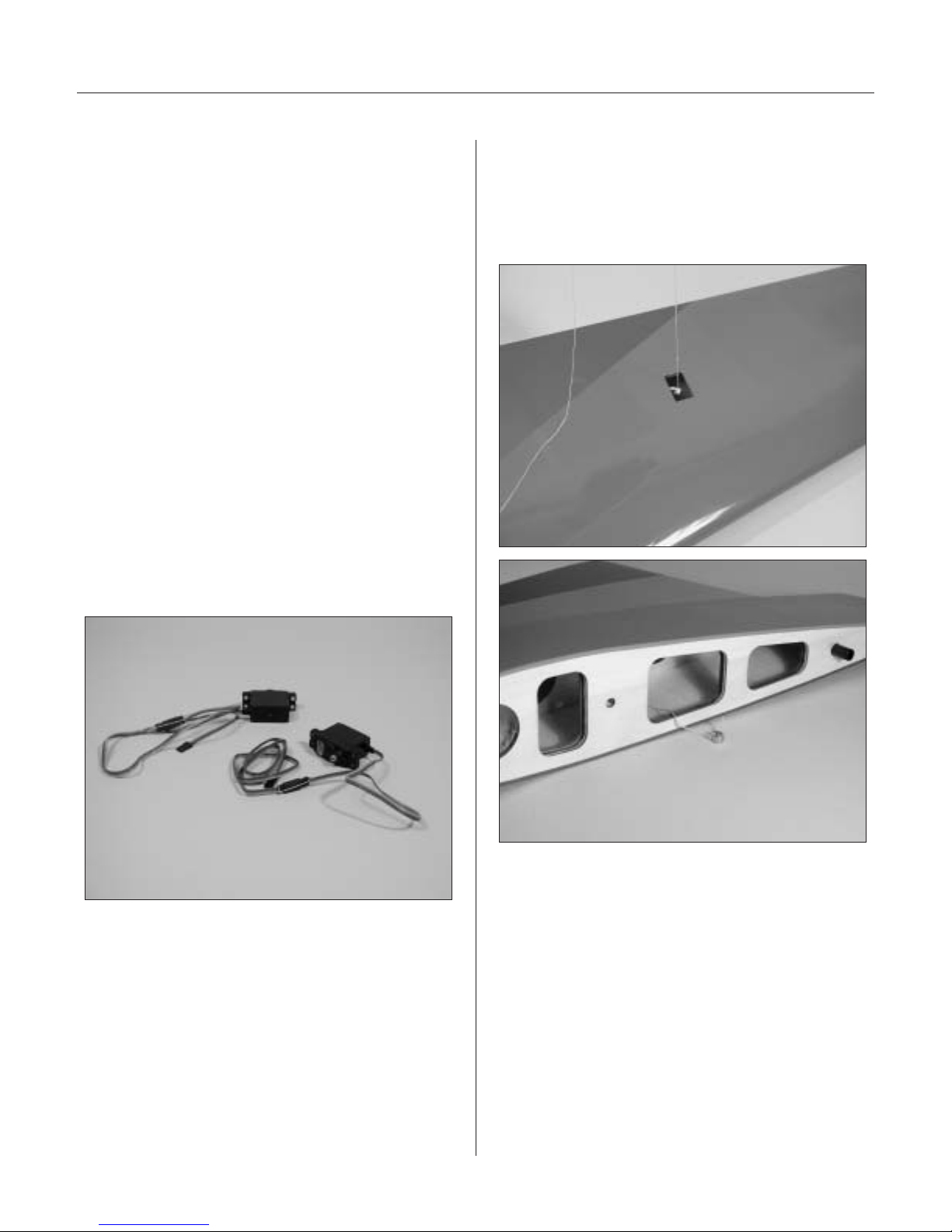
Step 2
Plug a 12" and a 24" servo extension onto two of
the servos. Either tie the servo leads together, using
a commercially available connector, or use unwaxed
dental floss to secure the extensions to prevent them
from coming loose during flight.
Step 3
Tie a weight to a piece of string. A wheel collar works
great in this application. Lower the string into the
wing from the aileron servo opening. Let the weight
drop out through the wing root for the servo.
Section 1 – Aileron Servo Installation
7
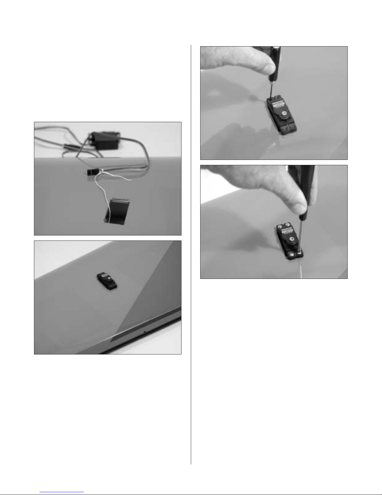
Step 4
Insert the servo with the 24" extension towards the
tip of the wing. Use the string to pull the servo lead
through the wing. Position the servo so the output
shaft is towards the trailing edge of the wing. Use
a 1/16” drill bit to drill the locations for the servo
screws. Mount the servos using the hardware
provided with the servos.
Step 5
Repeat Steps 3 and 4 for the servo near the root of
the wing panel.
Step 6
Repeat Steps 1 through 5 for the remaining
wing panel.
Photo for Step 4
Photo for Step 4
8
Section 2 – Aileron Control Horn Installation
Required Parts
• Wing panel (left and right)
• Aileron (left and right)
Required Tools and Adhesives
• Felt-tipped pen • Drill bit: 5/32"
• 8-32 tap • Tap handle
• Square • Ruler
• 30-minute epoxy • Rubbing alcohol
• Drill (drill press preferred)
• 8-32 x 2" Hangar 9
®
control horn screw (4)
(Included in HAN1220 (JR
®
) or HAN1221 (FUT))
• Hangar 9 control horn hex nut (4) (Included in
HAN1220 (JR) or HAN1221 (FUT))
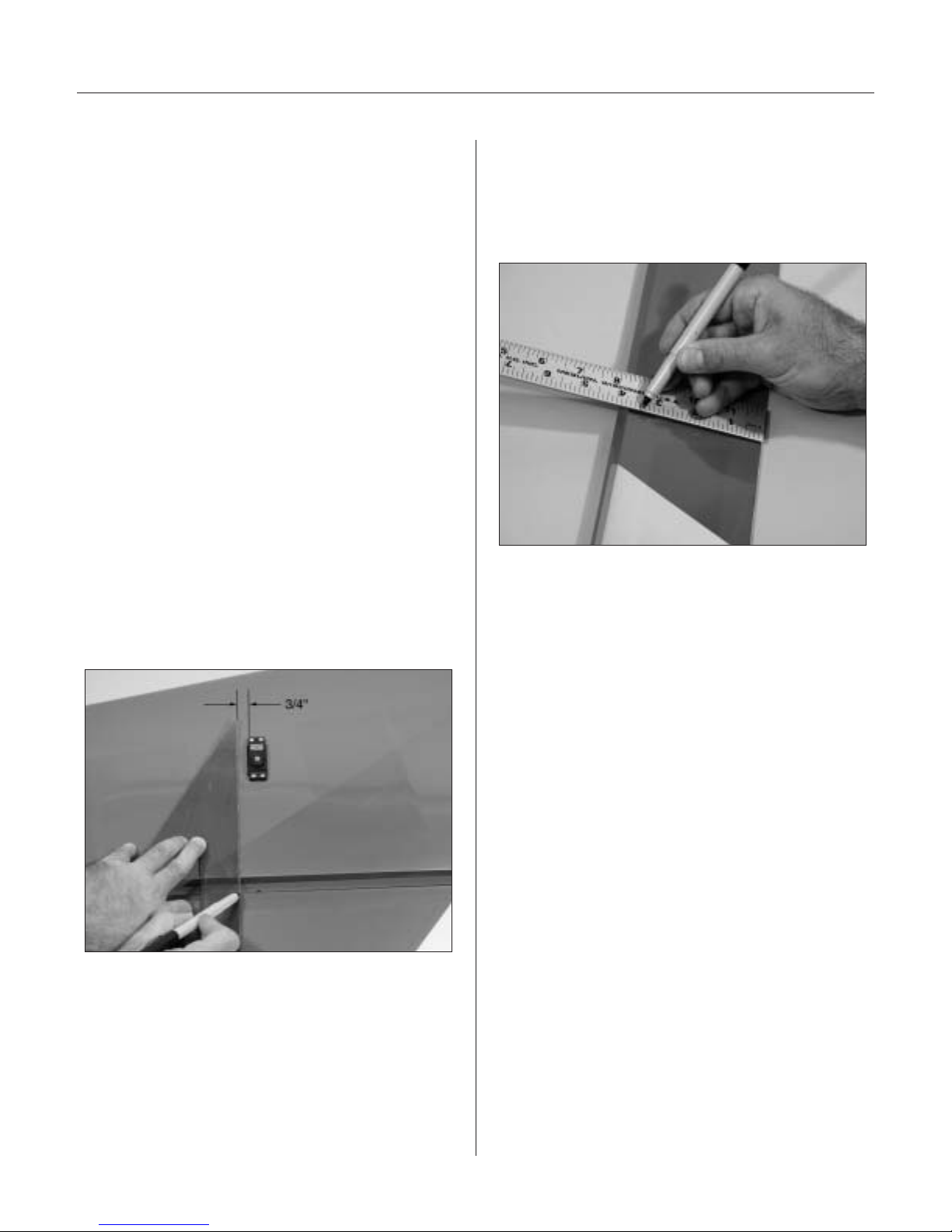
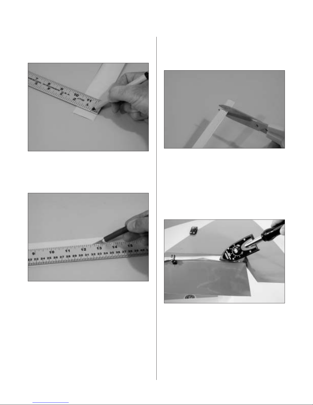
Step 1
Tape the aileron to the wing. Make a mark 3/4"
away from the edge of the servo towards the tip
of the wing. Using a square held in alignment (90°)
with the mark and with the trailing edge, mark the
aileron with a pen where the straight edge intersects
the aileron hinge bevel.
Step 2
Measure exactly 3
1
/2" forward from the trailing edge
of the aileron and make another mark using a felttipped pen. The intersection of the line from Step 1
and this line will be the position for the control horn.
Step 3
Repeat Steps 1 and 2 for the second control
horn location.
Step 4
Remove the ailerons from the wing. Use rubbing
alcohol to remove any tape residue.
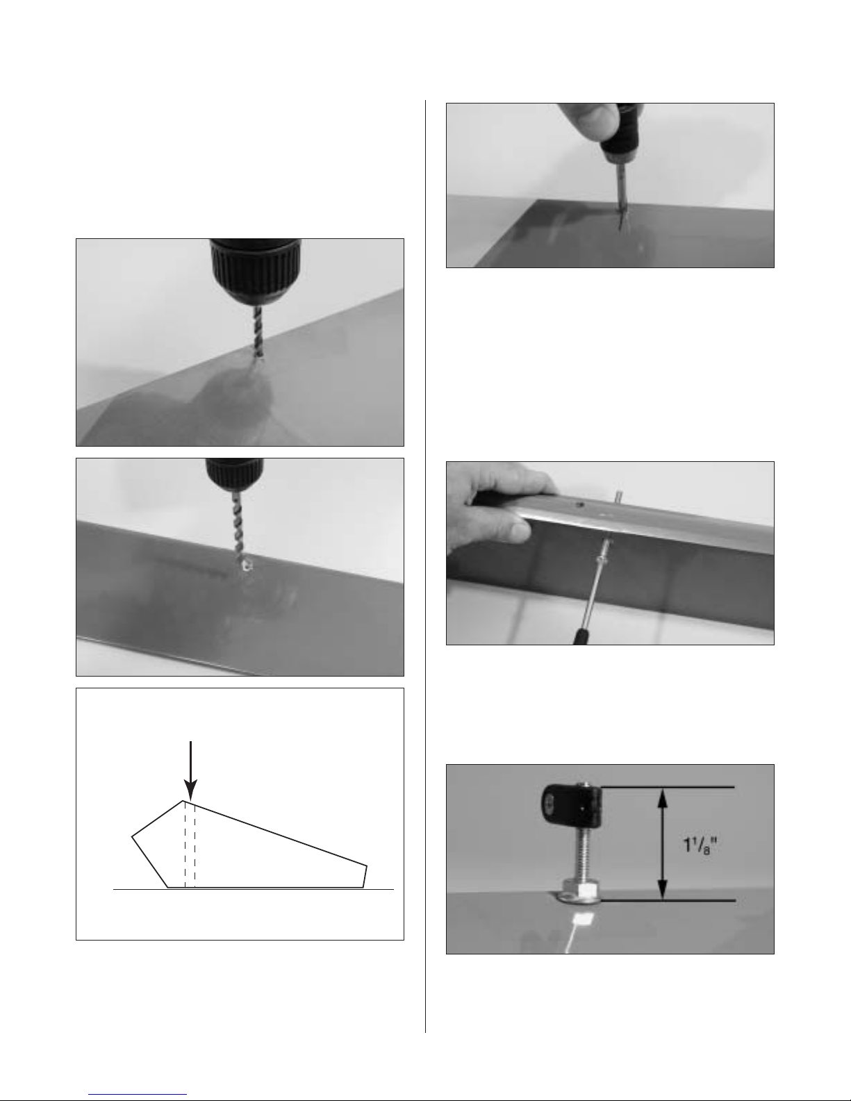
Step 5
Using a 5/32" drill bit and drill press, carefully drill
through the aileron at the marked position. Be
especially careful when penetrating through the top
surface of the aileron, as it’s easy to split out the
wood and rip the covering. Placing a wooden block
under the aileron and drilling slowly will prevent
these problems. If you choose to use the countersink
screws included in the Hangar 9® Hardware
Package, countersink the top of the aileron to allow
the screws to fit flush.
Section 2 – Aileron Control Horn Installation
9
Note: A hardwood block (hard point) is
located below the sheeting; you will be drilling
through this. Make sure to drill the hole
perpendicular to the top of the aileron.
It is highly recommended to use a drill press
to achieve this.
Step 6
Using an 8-32 tap, tap the hole just drilled
in the aileron.
Step 7
Mix a small amount of 30-minute epoxy and lightly
coat the inside of the tapped hole and the 8-32 x 2"
Hangar 9
®
control horn screw. From the top of the
aileron, screw the 8-32 x 2" into the tapped hole and
securely tighten. Wipe away any excess epoxy with
rubbing alcohol and a paper towel. Screw the hex nut
in place as shown. Allow the epoxy to fully cure.
Step 8
Screw the molded swivel link onto the 8-32 screw
until the distance from the aileron surface to the
top of the link is 1
1
/8".
Step 9
Repeat Steps 1 through 8 for the remaining aileron.
Photo for Step 6
Photo for Step 5
Photo for Step 5
Drill
Work Surface
10
Section 3 – Hinging and Sealing the
Control Surfaces
Required Parts
• Wing panel (right and left)
• Aileron (left and right)
Required Tools and Adhesives
• 30-minute epoxy • Syringe
• Sandpaper (coarse) • Toothpicks
• Robart hinge points
Properly hinging the control surfaces on giant-scale
models is vitally important! Poorly installed hinges
affect the model’s precision and control response and
can also be dangerous. Each and every hinge needs
to be securely bonded in place in both the flying
surface and the control surface. The hinge pivot
points need to be exactly parallel to each other and
precisely located on the center of the hinge line. We
regularly use Robart Super Hinge Points in all giantscale aircraft. They are easy to install, very strong,
and offer smooth friction-free control. The
Hangar 9
®
Edge 540 control surfaces are predrilled to
use Robart’s Super Hinge Points.
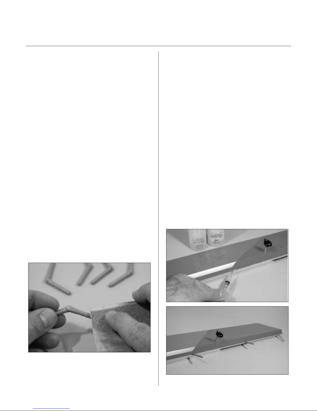
Step 1
Sand each end of the hinge point hinges using
coarse sandpaper. This will improve the bond of
the epoxy to the hinge.
Step 2
Mix 1 ounce of 30-minute epoxy. Using a glue
syringe or toothpick, place a sufficient amount of
30-minute epoxy into one of the hinge pockets in the
aileron leading edge. Install one of the hinge points
until the hinge pin center is flush with the leading
edge of the aileron. Some epoxy should ooze out of
the pocket as the hinge is installed. If not, remove the
hinge and apply more epoxy. After gluing a few
hinges, you’ll get the hang of just how much epoxy is
needed. Wipe away any excess epoxy with rubbing
alcohol. Recheck that the center of the hinge pin is
flush and parallel with the leading edge. Continue
installing hinges in the leading edge of the aileron.
The control surfaces (ailerons) will be installed after
the epoxy is fully cured.
Note: Be sure that the hinge pivot pins are
parallel and flush to the aileron leading edge.
It’s important to frequently mix a fresh batch
of 30-minute epoxy in order to achieve good
glue joint penetration. If you notice the epoxy
becoming thicker, then mix a new batch!

Section 3 – Hinging and Sealing the Control Surfaces
11
Step 3
Allow the epoxy to fully cure for at least 6 hours.
When cured, work each hinge throughout its full
motion several times using your hands. This will
break free any epoxy that may have found its way into
the hinge joint. Move the hinge throughout its full
travel until no resistance is felt. This may take as
many as 40 or 50 times.
Step 4
Mix 1 ounce of 30-minute epoxy. Using a syringe or
toothpick, place a sufficient amount of epoxy in each
of the hinge pockets in one wing panel.
Step 5
Carefully attach the aileron to the wing, making sure
the hinges are inserted in their respective hinge
pockets. Press the aileron and wing together such
that less than a 1/64" hinge line gap exists between
the aileron and wing. The bevels should virtually
touch. Use a paper towel and rubbing alcohol to wipe
away any visible epoxy around the hinges.
Step 6
Double-check the hinge gap and allow the epoxy
to fully cure for at least 6 hours. Now is a good
time to repeat Steps 1 through 5 for the remaining
wing panel and aileron.
12
Section 3 – Hinging and Sealing the Control Surfaces
Step 7
When fully cured, move each control surface
throughout its travel range several times to
break away any epoxy in the hinge. Be sure to
deflect the surface fully.
Section 4 – Sealing the Hinge Gaps
Step 1
Cut a piece of Clear UltraCote (not included) for
sealing the ailerons to approximately 3" x 42". Fold
the UltraCote down the center with the adhesive side
to the outside making a sharp crease at the fold.
Required Parts
• Wing panel (right and left)
• Aileron (left and right)
Required Tools and Adhesives
• Straight edge/ruler • Felt-tipped pen
• Scissors • Hobby knife w/#11 blade
• Clear UltraCote® (HANU964)
• Covering Iron (HAN101)
It’s imperative that the aileron and elevator hinge
lines be sealed airtight to prevent flutter. Sealing the
hinge line has several advantages. A sealed hinge
line gives a greater control response for a given
control deflection. It also offers more precise,
consistent control response and makes trimming
easier. Sealing the aileron and elevator hinge line is
mandatory. Failure to do so may cause control
surface flutter, resulting in a crash.
Section 4 – Sealing the Hinge Gaps
13
Step 2
Using a ruler, measure 1/2" from the folded crease
and mark two places with a felt-tipped pen.
Step 3
Using a sharp #11 blade and a straight edge,
carefully cut through both layers of UltraCote
®
covering at the 1/2" point marked in Step 2.
Step 4
Mark and cut the folded covering to an overall length
of 42". This piece will be inserted and ironed down
into the hinge bevel on the bottom of the aileron.
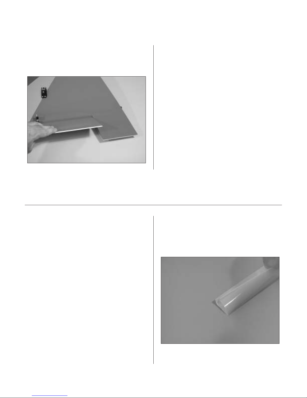
Step 5
Remove the backing from the UltraCote. Place
the folded crease side into the center of the hinge
line on the bottom of the wing. Using a straight edge
as shown, hold one side of the covering in place
while ironing down the opposite side with a sealing
iron. We recommend setting the iron temperature to
320° for this procedure.
Step 6
Fully deflect the aileron in the up position. Place the
straight edge over the hinge line covering that you
just ironed down in Step 5 with the edge of the
straight edge placed firmly at the bottom of the hinge
line as shown. Iron down this side of the covering,
making sure the aileron is fully deflected.
14
Section 5 – Aileron Linkage Installation
Required Parts
• Aluminum servo arms (4)
• Control horn ball ends (4)
• 4
1
/2" 4-40 linkage (4)
Required Tools and Adhesives
• Phillips screwdriver (small)
• Threadlock
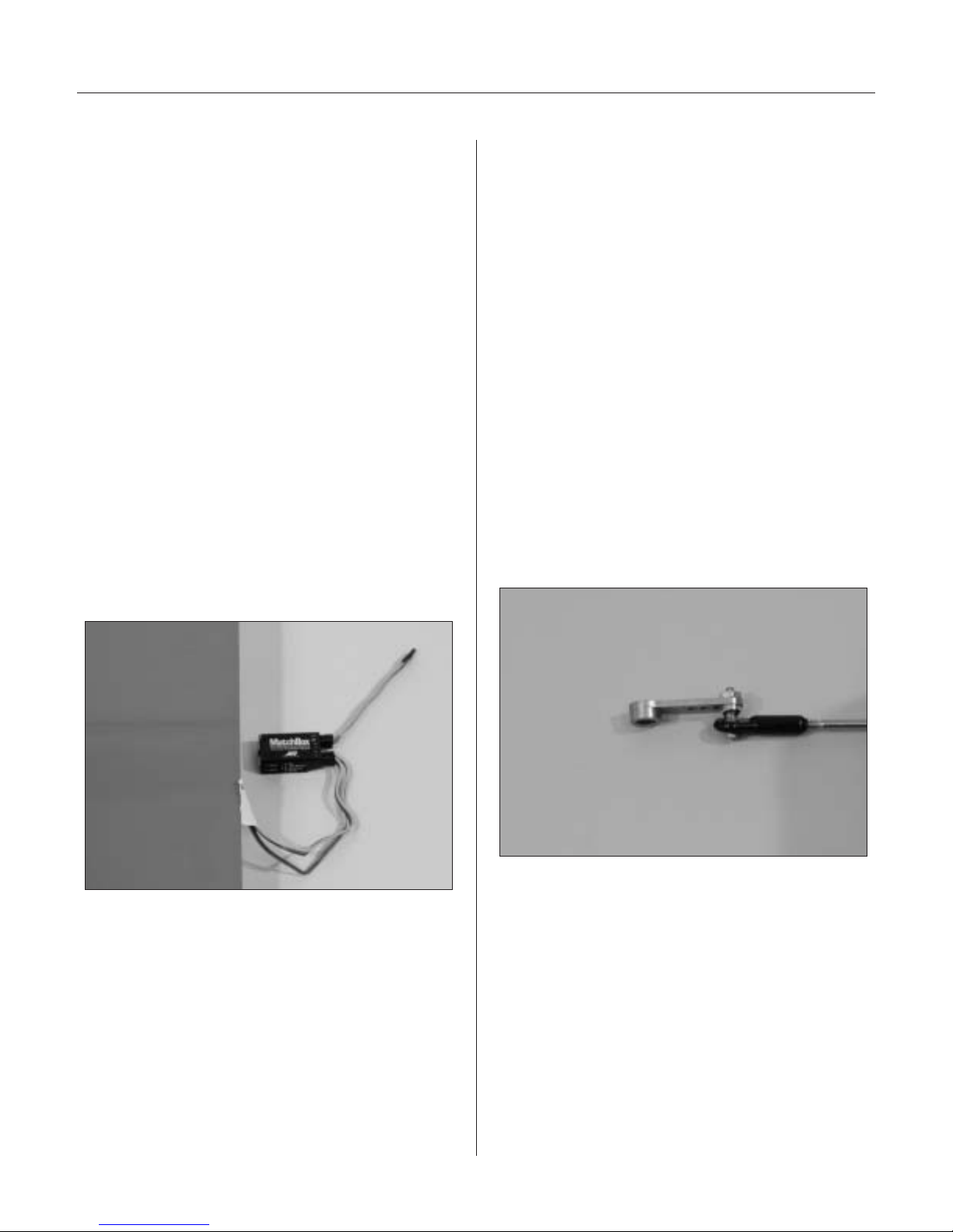
MatchBox Option: To simplify the installation of
the aileron servo linkages, you may want to use the
JR™ MatchBox™ servo matching/power system
(JRPA900). Four MatchBoxes would be used in this
application—one for each wing panel, one for the
rudder and one for the elevator servo configuration.
The MatchBox allows easy adjustment of the servo’s
center and endpoints, making radio setup a snap.
You can also use a separate battery to run the
MatchBox, reducing the load on the flight battery
powering the receiver.
Step 1
Screw a 4-40 ball link 5 to 6 turns onto each end of
a 4
1
/2" long 4-40 linkage. Adjust the linkage length
until the hole in the ball link aligns with the outer
hole in the servo arm when the aileron is neutral
and the servo arm is centered.
Note: Hangar 9®Titanium Pro-Links feature
right-hand threads on one end and left-hand
threads on the other, allowing for easy,
accurate adjustment without disconnecting
the linkages. Consistently putting the righthand threads toward the servo arms on all
servos will prevent you from getting confused
as to which way to turn the linkage to lengthen
or shorten the link. Hangar 9 also offers a
Pro-Link™ Wrench (HAN3558) to make
adjustments easier.
Step 2
Using the 4-40 screws (don’t substitute a standard
screw) and nuts included in the Hangar 9 package,
attach the ball link to the outer hole in the arm from
the bottom side as shown. The sequence is screw,
tapered standoff, ball link, servo arm and nut. Don’t
forget to use threadlock.
Step 3
Attach the servo horn to the servo using the screw
provided with the servo.
 Loading...