

Page 1

Wing Span .64-3/4 inches
Wing Area .712-1/4 inch2
Approx. Weight .4-3/4-5 1/2 lbs.
Engine Requirements .40-.46 2-cycle
.40-.50 4-cycle
• True UltraCote™ covering
• Positive self-righting flight characteristics
• 90% pre-built
• Extensive hardware kit included
• Break away motor mount prevents engine
damage during minor nose-overs
Specifications
Raising the Standard of Quality
in Almost-Ready-To-Fly Aircraft
ALMOST READY-TO-FLY
PRE-BUILT
90
%
9
HANGAR
TM
INSTRUCTION MANUAL
Page 2

2
TICKET TO FLY
R/C Pilot Program
The Total Training Package
Congratulations on your selection of the Hangar 9 Easy Fly
40! Your kit comes complete with the “T
ICKET
TO F
LY R/C
Pilot Program,” a detailed video instruction guide designed
to help beginners become successful pilots.
This video guides you through every step of the learning
process — from building tricks and tips through your first solo flights. The
video shows in-depth procedures on radio setup, trimming the plane, and
breaking-in and tuning your engine. It covers the basic flight concepts you
need to know, like takeoffs, landings and, most importantly, how to find and
work with a qualified instructor. You’ll find out just what to expect when
you arrive at the flying field… before you even get there.
When you use the video in conjunction with the complete, photo-illustrated
instruction manual, you’ll gain the confidence and ability to successfully
meet the challenge of R/C flight. This video is an invaluable teaching aid
which will shorten the time it takes to properly learn to operate and fly the
Easy Fly 40.
Good Luck and Good Flying!
TM
Page 3

3
Table Of Contents
Introduction 3
Contents Of Kit 4
Equipment Required 5
Tools And Supplies Required 5
Field Equipment Required 6
Optional Field Equipment 7
Section 1: Assembling The Wings 8
Section 2: Joining The Wing Halves 9
Section 3: Hinging The Rudder And Elevator 12
Section 4: Installing The Aileron Servo Trays 13
Section 5: Assembling The Fuselage 16
Section 6: Installing The Nose Gear 17
Section 7: Installing The Wing Dowels 18
Section 8: Assembling The Fuel Tank 19
Section 9: Installing The Fuel Tank 21
Section 10: Installing The Control Horns 22
Section 11: Installing The Horizontal & Vertical Stabilizers 24
Section 12: Installing The Engine 26
Section 13: Installing The Radio 29
Section 14: Installing The Linkages 32
Section 15: Setting Up The Radio 38
Section 16: Balancing The Model 39
Pre-Flight Check 40
Pre-Flight At The Field 41
Flight Instructions 42
AMA Safety Codes 43
Glossary 44
Page 4
Introduction
Congratulations!
You are the proud owner of the highest quality almost-ready-to-fly (ARF) sport trainer available. The Easy Fly
40 is professionally built and pre-covered by craftsmen using genuine UltraCote®covering. The positive selfrighting flight characteristics and excellent slow-speed handling make the Easy Fly 40 one of the easiest-to-fly
airplanes available. Beyond its positive, gentle flight mannerisms, the Easy Fly 40 also offers outstanding
sport aerobatic capabilities. Loops, rolls, sustained inverted flight, and even outside maneuvers are all well
within its flight envelope.
In order for you to get the best performance and most enjoyment from your Easy Fly 40, it is important to
carefully read and follow this manual. If you’re a first-time flier, we strongly suggest that you seek qualified
help during your first flights. Your local hobby shop will be able to put you in touch with qualified pilots and a
local club.
Note: Due to temperature changes during shipping, the covering on your Easy Fly may be slightly wrinkled.
The careful use of a heat gun or iron is recommended to shrink the UltraCote
®
until its taut.
Warning
An R/C aircraft is not a toy! If misused, it can cause serious bodily harm and damage to property. Fly only in
open areas, preferably AMA (Academy of Model Aeronautics) approved flying sites, and have an experienced
modeler/pilot preflight your aircraft before its first flight and perform the aircraft’s first test flights. Please
follow all instructions included with your radio and engine. We cannot stress strongly enough the importance
of having an experienced pilot preflight your aircraft and be present during your first test flights!
4
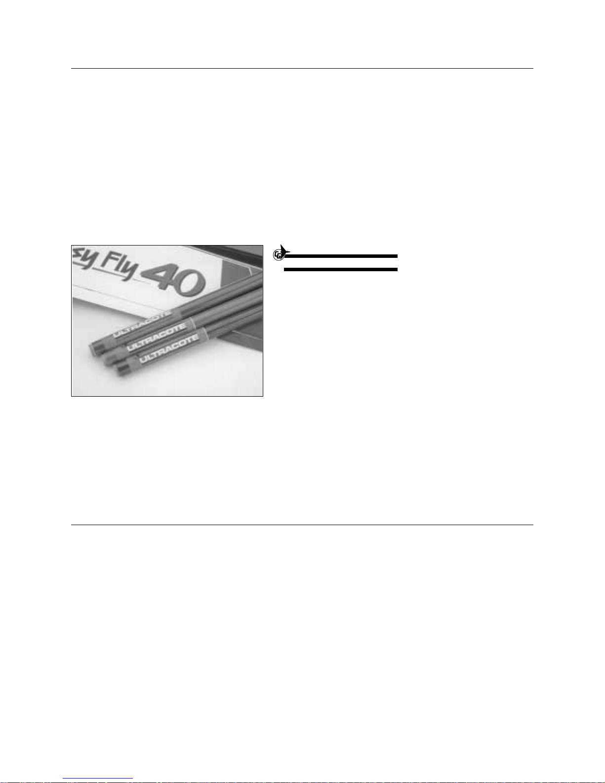
The Easy Fly 40 is professionally built and
pre-covered by craftsmen using genuine UltraCote®
covering. UltraCote is completely reparable and can
be found at your local hobby shop.
ULTRACOTE
UltraCote is a registered trademark of Carl
Goldberg Models
®
Page 5
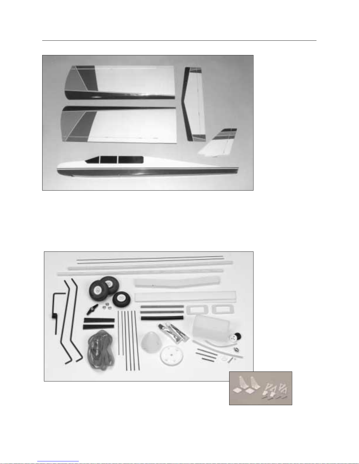
Contents Of Kit
5
A. Fuselage (#HAN1401)
B. Right wing half with aileron (#HAN1402)
C. Left wing half with aileron (#HAN1402)
D. Vertical stabilizer with rudder (#HAN1403)
E.
Horizontal stabilizer with elevator
(#HAN1404)
1. Pushrods
2. Aileron servo mounts (2)
3. Main landing gear
4. Nose landing gear
5. Spinner
6. Motor mounts and hardware
7. Wheels (3)
8. Fuel tank and hardware
9. Rubber bands (8)
10. Control horns
11. Wing joiner
A
B
C
E
D
1
11
9
8
7
6
5
4
3
2
10
Page 6
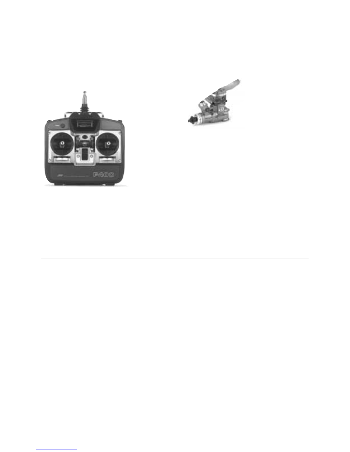
R/C Radio System
4 Channels (minimum)
4 Standard Servos
Standard 450-650 mAh Battery
Recommended JR Systems
JR F400 FM
JR XP642
JR XP783
JR XP8103
R/C Engine
.40-.45 2-Cycle with Muffler
Recommended Thunder Tiger Engine
GP .42 with Muffler
R/C Aircraft Propeller
10-6 Prop with a .40-.46 Size Engine
6
Equipment Required
Adhesives
CA (cyanoacrylate) Glue (instant/thin and medium viscosity)
CA Remover (dissolve)
5-Minute Epoxy
30-Minute Epoxy
Tools
Clips (e.g. clothespins, binder clips)
Cloth
Drill and Assorted Drill Bits
Heat Gun
Heat Iron
Hobby Knife
Masking Tape
Needle Nose Pliers
Paper Towels
Pencil
#1 and #2 Phillips Screwdrivers
Rubbing Alcohol
Ruler (straight edge)
Sandpaper
Scissors
Straight Screwdriver
Thread Lock (e.g., Loc Tite Blue)
Toothpicks
90-Degree Triangle
Wax Paper
Z-Bender Pliers
Tools And Supplies Required
Page 7
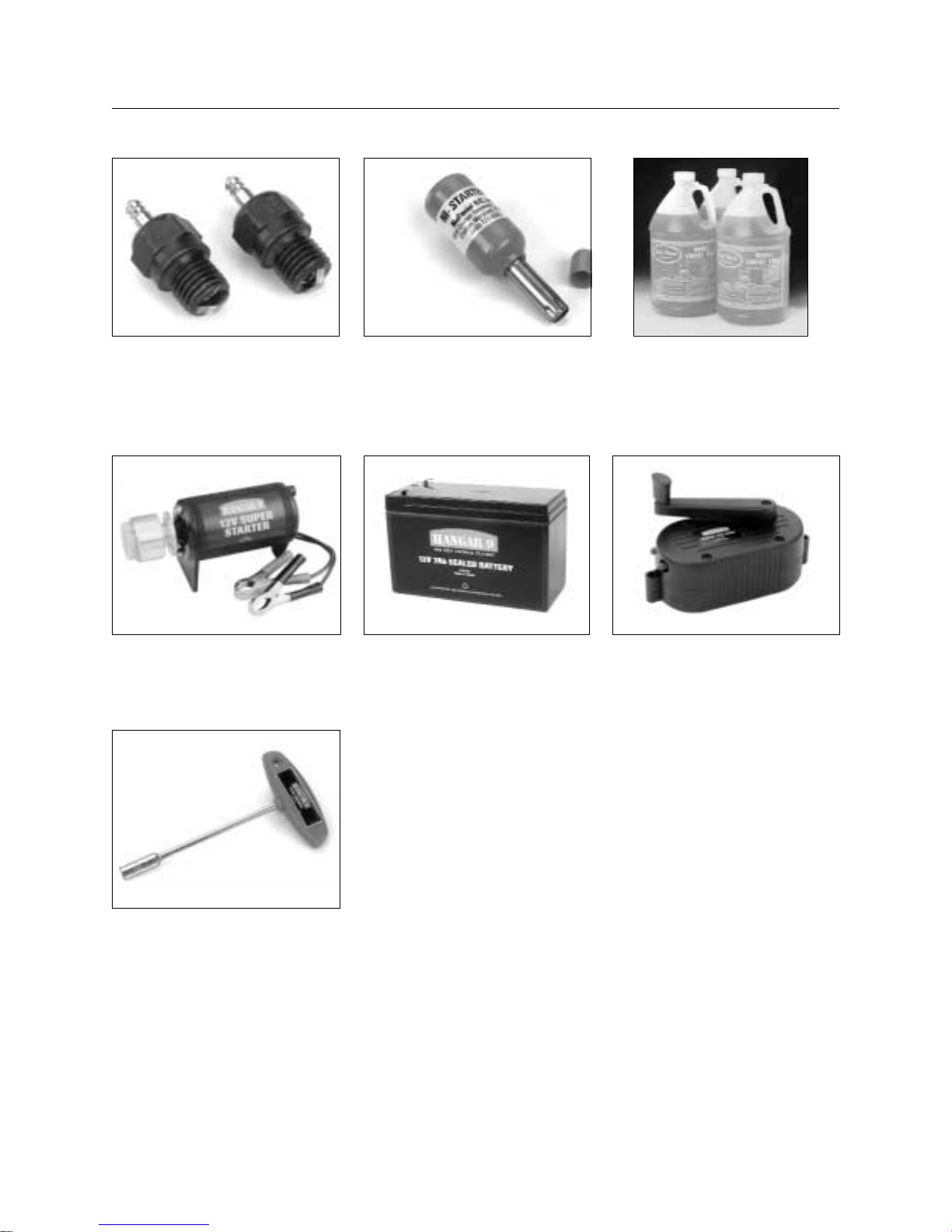
Field Equipment Required
HAN3000 – 2-cycle Performance Plug MDC101 Glow Driver Model Airplane Fuel
HAN 3005 – Extra Life Sport Plug
HAN104 12V Super Starter HAN102 12V Battery HAN118 Fuel Pump
HAN2510 Glow Plug Wrench
7
Page 8
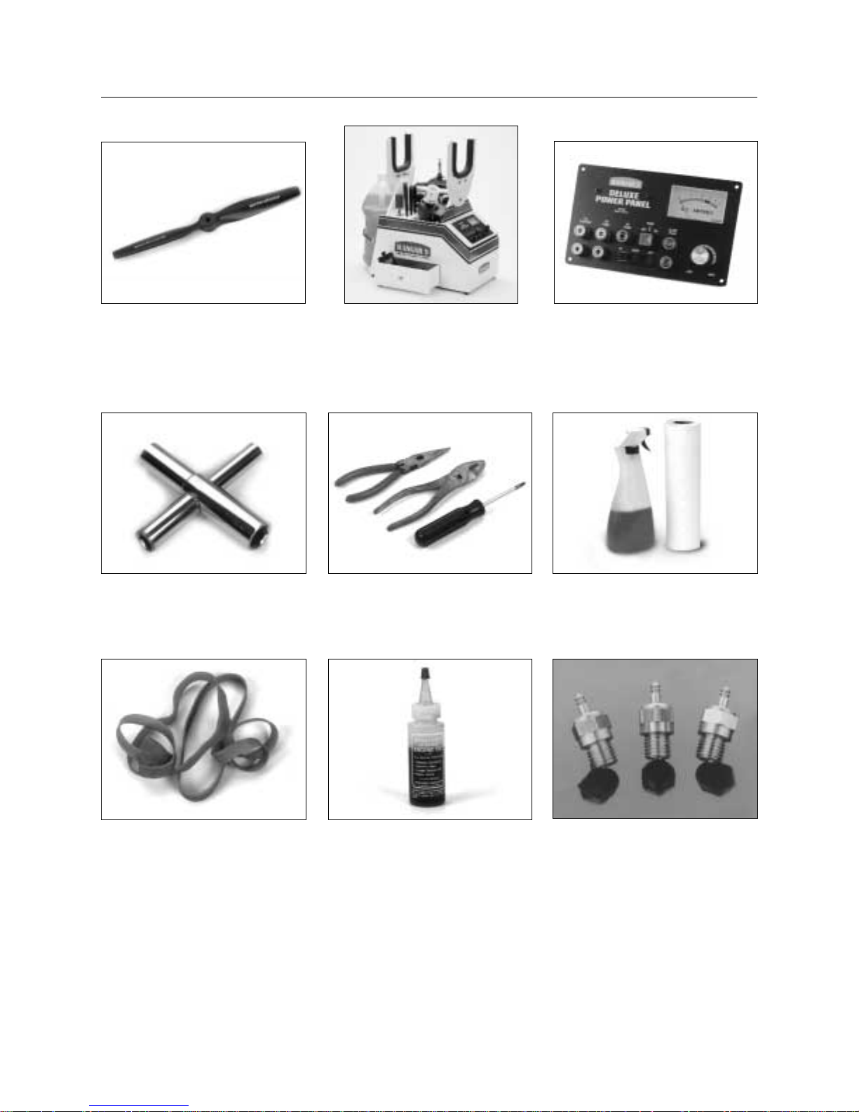
Optional Field Equipment
Extra Propellers Flight Box Power Panel
Prop Wrench Miscellaneous Tools Paper Towels
#64 Rubber Bands After Run Oil Extra Glow Plugs
8
Page 9
❑ 1. Carefully remove the aileron from the right wing panel.
Note where the hinges and the aileron torque rod fit into
the aileron.
❑ 2. Mix a small amount of 30-minute epoxy, carefully
following the instructions included with the epoxy.
❑ 3. Using a toothpick, apply epoxy into the ailerons’ torque
rod hole. Fill the hole 1/2 full.
❑ 4. Replace the aileron on the right wing half. Make sure
the hinges slide in place and the aileron torque rod
inserts into its respective hole in the aileron. The gap
between aileron and wing should be a constant 1/16”.
❑ 5. Wipe off any excess epoxy using a paper towel and
rubbing alcohol.
❑ 6. Deflect the aileron and apply a small amount of thin CA
glue to each hinge. Make sure that the CA glue
penetrates into the aileron and wing while maintaining a
1/16” aileron gap.
❑ 7. Wipe off any excess CA glue using CA remover and a
paper towel.
❑ 8. Repeat this process for the left wing (Steps 1-7).
Note:
After the CA has dried completely, check to ensure that
the hinges are secure by pulling firmly on the ailerons.
Important:
The ailerons are fitted in place but not glued in. They
must be correctly glued prior to flying.
9
Left Wing Panel with Aileron and Hinges
Right Wing Panel with Aileron and Hinges
CA Remover
30-Minute Epoxy
Thin Instant CA Glue
Paper Towels
Rubbing Alcohol
Toothpicks
Section 1: Assembling The Wings
Parts Needed Tools Needed
Page 10
❑ 1. Using a pencil, mark both wing roots (the exposed
wood end of the wing halves) as shown.
❑ 2. Using a hobby knife, carefully cut out the marked
section.
Important:
Do not cut into hard wood wing joiner section.
10
Aileron Servo Mounts (2)
Dihedral Brace
Left Wing Half from Section 1
Right Wing Half from Section 1
Standard Servo (1)
30-Minute Epoxy
Hobby Knife
Masking Tape
Paper Towels
Pencil
Rubbing Alcohol
Ruler
Wax Paper
Section 2: Joining The Wing Halves
Parts Needed Tools Needed
Page 11
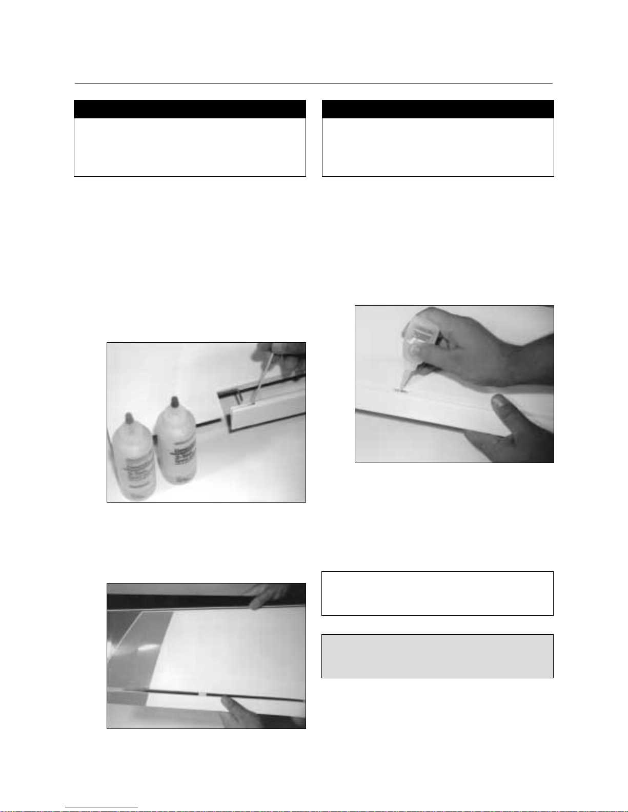
❑ 3. Locate the dihedral brace (also called the wing joiner).
Using a ruler and pencil, mark the exact center of the
brace as shown.
❑ 4. Mix approximately 2 ounces of 30-minute epoxy. In
this step, be sure to use plenty of epoxy. Using a scrap
piece of wood, smear the epoxy into the wing joiner
cavity of both wings. (Remember, use plenty of epoxy.)
❑ 5. Coat one half of the dihedral brace with epoxy up to the
line. Note the orientation of the V of the dihedral
brace. Install the epoxy-coated side of the dihedral
brace into a wing half up to the line, making sure the V
of the dihedral brace is positioned correctly as shown.
11
Section 2: Joining The Wing Halves
CONTINUED
Page 12
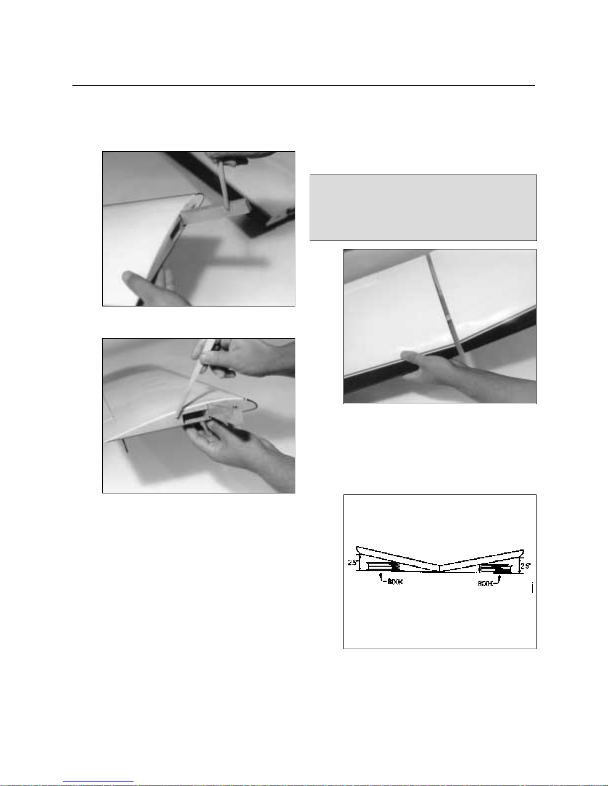
❑ 6. Apply epoxy to the exposed area (other end) of the
dihedral brace. Uniformly coat both wing roots with
30-minute epoxy.
❑ 7. Carefully slide the two wing halves together. Firmly
press the two halves together, allowing the excess
epoxy to run out. Using rubbing alcohol and a paper
towel, clean off the excess epoxy.
Important:
Be sure the wings are pressed firmly together at the
center section. Be sure that the leading and trailing
edges line up properly. Use masking tape as necessary
to hold the wing halves in position.
❑ 8. Place a 12” x 12” sheet of wax paper on the edge of a
flat table. Place the center section of the wing on the
wax paper with the aileron torque rod hanging off the
edge of the table. Prop up each wing tip 2-1/2 inches
off the table as shown. Books work well for this.
❑ 9. Wipe off any excess epoxy using rubbing alcohol and
paper towels. Allow the wing to set undisturbed
overnight to dry completely.
12
Section 2: Joining The Wing Halves
CONTINUED
Page 13
13
Horizontal Stabilizer with Elevator and Hinges
Vertical Stabilizer with Rudder and Hinges
CA Remover
Paper Towels
Thin Instant CA Glue
Section 3: Hinging The Rudder And Elevator
Parts Needed Tools Needed
❑
1. Push the elevator and horizontal stabilizer together until
there is a constant 1/16” gap between the two and the
edges are lined up correctly.
❑ 2. Deflect the elevator and apply thin CA glue at the
hinges so that it absorbs both into the stabilizer and the
elevator (4 places).
❑ 3. Using the same technique, hinge the rudder to the
vertical stabilizer.
❑ 4. Wipe off any excess CA using CA remover and a paper
towel. Set these assemblies aside for now.
Note: After CA has dried completely, check to ensure that the
hinges are secured by pulling firmly on the control
surfaces.
Page 14
14
❑ 1. Mix a small amount of 5-minute epoxy as per the
instructions included with the epoxy. Remember, once
this epoxy is mixed, you have only 5 minutes of
working time until it dries.
❑ 2. Spread a thin layer of epoxy over the entire surface of
one side of an aileron tray.
❑ 3. Join the two aileron trays as shown and clamp them
together using four clips. Be sure the two trays are
properly aligned. Wipe off any excess epoxy with a
paper towel and set aside to dry for 15 minutes.
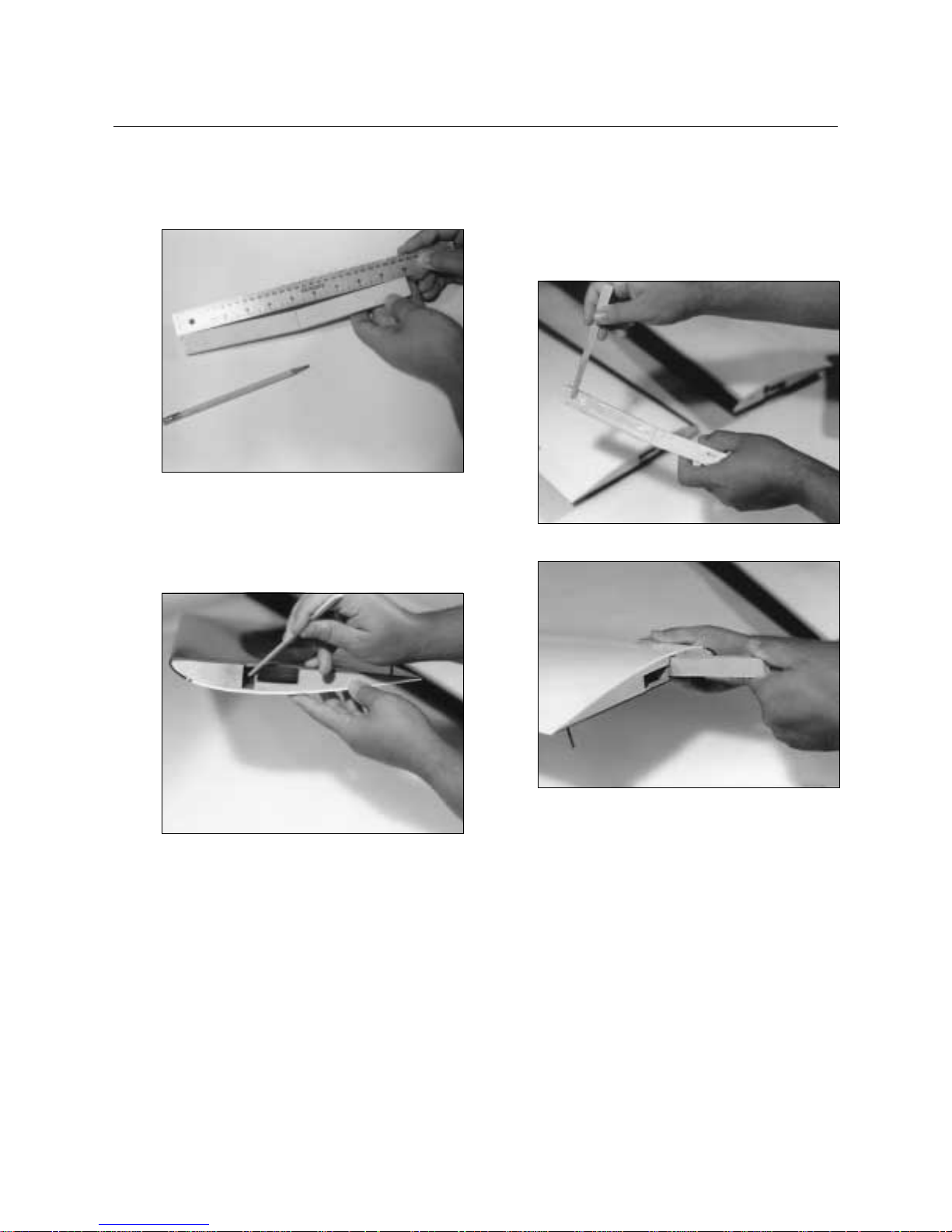
❑ 4. Using a ruler, measure the distance on the bottom of
the wing at the center line 5-1/2 inches from the trailing
edge and mark with a pencil.
❑ 5. Next, measure 3-3/4 inches from the leading edge back
to the center line and mark with a pencil.
Aileron Servo Trays (2)
Wing Center Section Tape
Clips (e.g., clothespins,
binder clips) (4)
5-Minute Epoxy
Hobby Knife
Masking Tape
Paper Towels
Pencil
Ruler
Section 4: Installing The Aileron Servo Trays
Parts Needed Tools Needed
Page 15

15
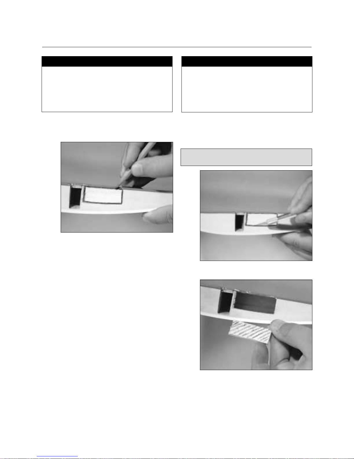
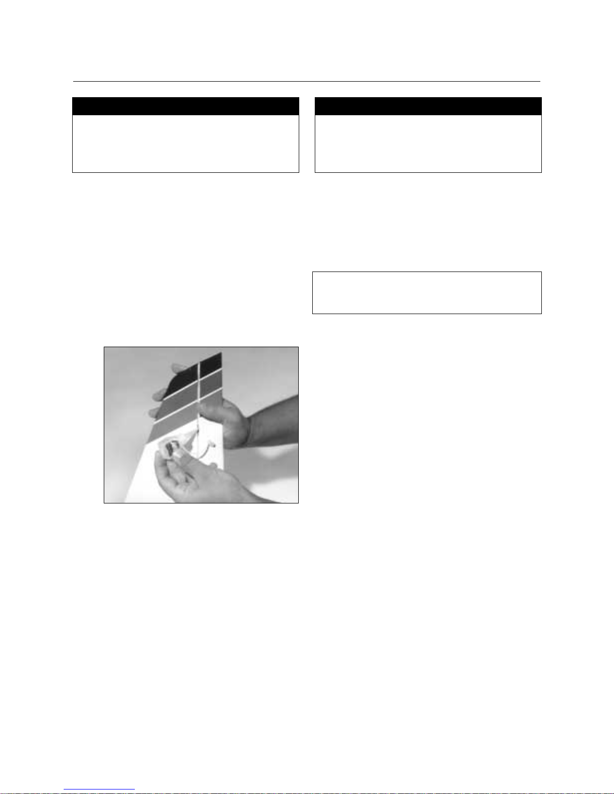
❑ 6. Unclamp the aileron tray when dry and position it on
the center line so the two marks are visible on the
inside of the aileron tray.
❑ 7. Carefully trace around the outside of the aileron tray
using a pencil.
❑ 8. Remove the aileron tray. Using a sharp hobby knife,
carefully cut through the plastic covering. Be careful
not to cut into the wood on the line you just made in
Step 7.
❑ 9. Carefully remove the covering in the aileron tray area.
This is necessary so that the tray will properly adhere to
the wing.
❑ 10. Mix a small amount of 5-minute epoxy and spread it
over the entire area of one side of the servo tray.
S
ection
4: Installing The Aileron Servo Trays
CONTINUED
Page 16

16
❑ 11. Place the aileron tray, glue side down, on the exposed
wood area on the bottom of the wing and gently press it
into position. Use masking tape if necessary to hold in
position until dry. Allow 15 minutes for the epoxy to
cure.
❑ 12. Using a sharp hobby knife, carefully cut out the balsa
wood from the inside section of the aileron tray and
remove.
❑ 13. Locate the wing center tape (white adhesive-backed
tape) and remove the adhesive backing. Starting at the
edge of the aileron tray, apply the tape around the wing
at the center section, ending at the other side of the
tray. Use a hobby knife to trim the excess length of
tape. Your wing is now complete.
❑ 14. Locate the small blue decal (square in shape) on the
decal sheet included with your kit. Apply this decal to
the leading edge of the wing to cover the wing center
tape that you have just applied. Press firmly to ensure
that the decal adheres properly to the wing.
S
ection
4: Installing The Aileron Servo Trays
CONTINUED
Page 17

17
❑ 1. Locate the main landing gear slot in the bottom of the
fuselage. Position the two landing gear straps across
the slot as shown and drill four 1/16” holes using the
straps as a guide. Remove the straps after all four holes
are drilled.
❑ 2. Locate the two main landing gear struts and insert them
into the landing gear slot as shown. Make sure the ends
fit into the holes in the edges of the slot.
❑ 3. Reposition the landing gear straps over the 1/16” hole
you drilled in Step 1. Screw into position with the four
sheet metal screws provided.
❑ 4. Place the wheels on the ends of the struts and secure
them with the supplied wheel collars. Use thread lock
on the collar screws.
Fuselage
Main Landing Gear (2 pcs)
Main Landing Gear Hardware
Wheels (2 pcs)
Wheel Collars with Screws (2 pcs)
Drill with 1/16” Drill Bit
#1 and #2 Phillips Screwdrivers
Thread Lock
Section 5: Assembling The Fuselage
Parts Needed Tools Needed
Page 18

18
❑ 1. The nose gear mount is pre-assembled onto the front
firewall of the fuselage. Locate the nose gear. On the
straight end, first slide the steering arm onto the nose
gear (note the orientation as shown in the photo). Use
thread lock and a #2 Phillips screwdriver to secure the
steering arm in place. Next, install a collar and secure it
in place with the thread lock and a machine screw. Now
slide the spring into position.
❑ 2. Insert the nose gear assembly from Step 1 into the nose
gear mount (attached to the front of the fuselage). Be
sure the spring stays in position and rests against the
nose gear mount. Install the collar on the top end of the
landing gear flush with the landing gear, and secure it
into position with a screw and the thread lock.
❑ 3. Attach the nose wheel and hold it in place using a
wheel collar and screw.
Nose Gear Wheel (1)
Spring Wheel Collar with Screws (2)
Steering Arm
#2 Phillips Screwdriver
Thread Lock
Section 6: Installing The Nose Gear
Parts Needed Tools Needed
Page 19

19
❑ 1. Using a sharp hobby knife, carefully cut the covering
around the four holes as shown, leaving a circle that the
dowel will be pressed into.
❑ 2. Install the two dowels and position them so that an
equal amount of dowel extends from each side of the
fuselage. Using thin CA glue, apply five drops around
each side of the wing dowel (4 places) where the dowel
touches the fuselage.
❑ 3. If necessary, use a paper towel and CA remover to wipe
off any excess CA glue.
Fuselage
Wing Dowels (2)
CA Remover
Hobby Knife
Paper Towel
Thin Instant CA Glue
Section 7: Installing The Wing Dowels
Parts Needed Tools Needed
Page 20

20
Clunk (brass fuel pickup)
Copper Tube, Long (vent)
Copper Tube, Short (pickup)
Fuel Line, Small
Fuel Tank
Plastic Cups (2)
Rubber Stopper
3mm Screw and 3mm Nut
Hobby Knife
#1 Phillips Screwdriver
Section 8: Assembling The Fuel Tank
Parts Needed Tools Needed
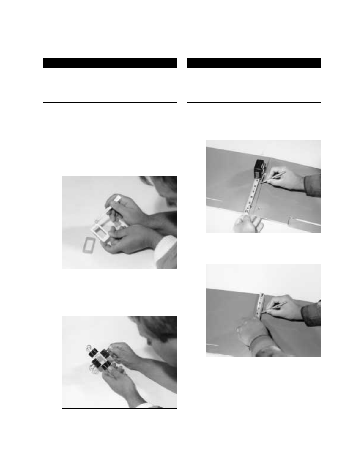
❑
1. Locate the black rubber stopper. Insert the short copper
tube into one of the open holes in the stopper so that an
equal amount of tube extends from each side. This tube
will be the fuel tank pickup tube.
❑ 2. Locate the long copper tube and bend it using your
fingers, as shown. This tube will be the fuel tank vent
tube.
❑ 3. Slide this tube into the other open hole of the stopper,
as shown.
❑ 4. Slide the two white plastic caps over the copper tubes
as shown. Note the orientation of the caps. The small
inside cap and the three “pegs” face away from the
black rubber stopper. The large outside cap and the
“raised center” go away from the black rubber stopper.
Page 21

21
❑ 5. Locate the small diameter fuel tubing and cut it to 3”
in length. This tubing will be used for the fuel pick-up
inside the fuel tank. Insert the brass clunk into one end
of the fuel tubing.
❑ 6. Install the open tube end of the clunk and tubing
assembly on the short copper tubing.
❑ 7. Press the 3mm locknut between the three pegs on the
inside white plastic cap as shown.
❑ 8. Carefully insert the assembly into the fuel tank. Note the
position of the vent tube. It must be at the top of the fuel
tank to function properly.
Section 8: Assembling The Fuel Tank
CONTINUED
Page 22

22
Section 8: Assembling The Fuel Tank
❑ 9. Insert a 3mm screw into the center hole of the stopper
and tighten.
Important:
Remember which tube is the fuel pick-up and which is
the vent so that you can properly connect the fuel tank
to the engine in Section 12.
CONTINUED
Fuel Tank Assembly (from Section 8)
Fuselage
None
Section 9: Installing The Fuel Tank
Parts Needed Tools Needed
❑
1. Note that the fuel stopper is mounted closer to one
edge of the tank than the other. This “closer edge” is
the top of the tank. Slide the tank into the fuselage
stopper first. Make sure that the top of the tank is
positioned towards the top of the fuselage.
❑ 2. Press the tank into position until the stopper inserts
into the hole in the firewall. The white plastic cap will
be nearly flush with the firewall.
Page 23

23
❑ 1. Position one of the control horns on the bottom of the
elevator as shown. The vertical section of the control
horn must be positioned exactly in line with the cutaway portions of the covering, and the four holes must
be in line with the hinge.
❑ 2. Using a pencil, mark the position of the two screws on
the elevator. Next, drill two 1/16” holes through the
elevator where marked.
❑ 3. Install the control horn using the two screws and the
back plate and tighten the screws with a #1 Phillips
screwdriver.
❑ 4. Using a pencil, measure up 1/2” from the bottom of the
rudder and mark.
Control Horn with Backplate (2)
Horizontal Stabilizer with Elevator
Small Phillips Screw (4)
Vertical Stabilizer with Rudder
Drill with 1/16” Drill Bit
Pencil
#1 Phillips Screwdriver
Ruler
Section 10: Installing The Control Horns
Parts Needed Tools Needed
Page 24

24
❑ 5. Position the rudder control horn as shown, with the
mark just below the edge of the control horn.
❑ 6. Now mark, drill, and install the horn as you did
previously for the elevator.
Section 10: Installing The Control Horns
CONTINUED
Page 25

25
Section 11: Installing The Horizontal & Vertical Stabilizers
❑ 1. Using a hobby knife, carefully cut out the covering at
the front of the horizontal stabilizer slot as shown. The
vertical stabilizer will later be inserted into this slot.
❑ 2. Using a hobby knife, carefully cut out the openings on
the top rear of the fuselage. Also, cut out the plywood
section in the rear-most slot. The rear-most cutout is
where the vertical fin will fit; the forward cutout is for
the rudder pushrod exit.
❑ 3. Position the horizontal stabilizer in place on the
fuselage and trial fit the vertical stabilizer in place.
Using a pencil, mark where the horizontal stabilizer and
vertical stabilizer meet on the vertical fin on both sides.
❑ 4. Remove the vertical stabilizer and cut away the covering
below the marked section. Be careful not to cut into the
wood. A ruler is helpful in making a straight cut.
Fuselage
Horizontal Stabilizer Assembly
Vertical Stabilizer Assembly
Hobby Knife
Ruler
30-Minute Epoxy
90-Degree Triangle
Pencil
Rubbing Alcohol
Paper Towels
Parts Needed Tools Needed
Page 26

26
Section 11: Installing The Horizontal & Vertical Stabilizers
❑ 5. Mix approximately 1 ounce of 30-minute epoxy. Apply
a generous amount of epoxy to the rear fuselage section
where the horizontal stabilizer mounts. Also apply
epoxy to the exposed balsa wood on the bottom of the
horizontal stabilizer.
❑ 6. Install the horizontal stabilizer by pressing it into
position. Carefully align the horizontal stabilizer to the
fuselage.
❑ 7. Apply 30-minute epoxy to the area on the vertical
stabilizer
wood section from which you cut the covering
in Step 4
.
❑ 8. Carefully insert the vertical stabilizer into the horizontal
stabilizer as shown. Be sure that it fully seats. Wipe
away the excess epoxy with rubbing alcohol and a
paper towel.
❑ 9. Using a 90-degree triangle, align the vertical stabilizer
exactly perpendicular to the horizontal stabilizer.
APPLYING THE DECALS
Using the box cover as a guide, simply apply the decals
to their proper locations.
CONTINUED
Page 27

27
Engine (not included)
Engine Mounts (2)
Engine Screws, Nuts, Washers (8)
Fuel Tubing
Fuselage
❑ 1. Locate the two engine mounts. Note that they are cut on
an angle. They are designed to put right thrust into the
engine.
❑ 2. Place the engine mounts, as shown, in the front of the
fuselage, noting the angled edges. Position the engine
to the right (right thrust). Trial fit the engine in place.
Using a pencil, mark the position of the four holes that
secure the mounts to the fuselage, as shown.
❑ 3. Remove the mounts and drill four 1/8” holes at the
points you marked.
❑ 4. Reposition the engine mounts and engine on the
fuselage, making sure right thrust is achieved, and
mark through the holes in the engine mount with a
pencil.
Note: Motor mount in fuselage is designed with 8° of
downthrust.
Drill with 1/8” Drill Bit
Pencil
#2 Phillips Screwdriver
Section 12: Installing The Engine
Parts Needed
Tools Needed
Page 28

28
❑ 5. Remove the engine and mounts and drill four 1/8”
holes through the fuselage where marked.
❑ 6. Place the motor mounts back into the fuselage and
fasten them into place with four of the screws, washers,
and nuts provided.
❑ 7. Place the engine and the motor mounts in the desired
position. It is helpful to have the prop and spinner
installed at this time to check the clearance. Using a
pencil, carefully mark the engine mount through the
holes in the engine mount flange. Remove the engine
and drill four 1/8” holes where marked.
❑ 8. Secure the engine in place using the four remaining
screws, nuts, and washers.
Section 12: Installing The Engine
CONTINUED
Page 29

29
❑ 9. Install the muffler per the instructions included with the
engine. Now install the fuel tubing. Connect the vent
tube from the fuel tank to the muffler nipple and the
other tube from the fuel tank to the carburetor nipple.
Special Instructions for Installing a 4-Cycle
Engine
The Easy Fly 40 is designed to also accept .40-.65
4-cycle engines. The installation is similar to the
2-cycle engine installation except that it may be
necessary to trim away some of the plywood in the
nose of the fuselage in order to allow the wider 4-cycle
engine ease of clearance.
Section 12: Installing The Engine
CONTINUED
Page 30

30
Installing the Aileron Servo
❑
1. Locate the wing and one of the standard servos. Put
the servo grommets and eyelets in the servo and place
the servo in the aileron mount. Using a pencil, mark the
four places to be drilled.
❑ 2. Remove the aileron servo and drill four 1/16” holes
where marked.
❑ 3. Place the aileron servo back in its mount and secure it
in place with the four screws included with the servo.
4-Channel Radio System with 4 Standard Servos and
Hardware (not included)
Fuselage
Radio Packing Foam (not included)
Wing
Drill with 1/16” Drill Bit
Hobby Knife
Pencil
#1 Phillips Screwdriver
Section 13: Installing The Radio
Parts Needed Tools Needed
Page 31

31
Installing the Rudder, Elevator, and Throttle
Servos
❑
1. Locate the other three servos and install the grommets
and eyelets in all three per the instructions included
with the radio. Place the servos in the servo tray in the
fuselage as shown, noting the position of the output
horns. Using a pencil, mark the 12 servo mounting hole
positions.
❑ 2. Remove the servos and drill twelve 1/16” holes where
marked. Install the servos, noting the position of the
output horns. Screw in place with the 12 screws
included with the servos.
Installing the Receiver and Battery
❑
1. Radio packing foam (available at your local hobby
shop) should be used to install the receiver and battery.
With a sharp hobby knife, cut a layer of foam the size of
the compartment in front of the servo tray and place it
in the bottom of the fuselage. Then, cut out another
layer of foam and cut out the center section to match
your battery pack.
❑ 2. Cut out another layer of foam and place it on top of the
battery. Cut out the next layer so that it clears the
receiver. You then have a solid top layer over the top of
the receiver.
Important:
Run the antenna through the fuselage and out the rear.
Section 13: Installing The Radio
CONTINUED
Page 32

32
Installing the Switch
❑
1. The switch should be mounted on the left side of the
fuselage, away from the exhaust gases. Place the
switch plate against the side of the fuselage, as shown,
and mark the position of the holes and square.
❑ 2. Using a sharp hobby knife, cut out the marked area and
drill holes to allow the switch to be mounted. Mount
the switch using the hardware provided.
Section 13: Installing The Radio
CONTINUED
Page 33

33
Installing the Aileron Linkage
❑
1. Locate the wing, two aileron horns, two threaded rods,
and two clevis. Using the Z-Bender pliers, make a zbend 4-1/8 inches from the threaded end of both rods
and cut off the extra length of rod.
❑ 2. Screw a clevis onto the threaded portion of both rods.
❑ 3. Select an X servo horn and trim the long arms off as
shown.
❑ 4. Install the servo horn on the aileron servo, as shown.
Install the z-bends in the second, outermost hole from
the center of the servo horn, as shown.
Aileron Horn (2)
Balsa Dowel (2)
Fuselage and Wing
Heat Shrink Tubing
1/16” Plain Rod, Long (2)
1/16” Plain Rod, Short (2)
Plastic Clevis (4)
1/16” Threaded Rod (4)
Drill with 1/16“ Drill Bit
Heat Gun
Hobby Knife or Scissors
Needle Nose Pliers
Thick CA Glue
Z-Bender Pliers
Section 14: Installing The Linkages
Parts Needed Tools Needed
Page 34

34
❑ 5. Screw both aileron horns onto the aileron torque rods
until the threaded portion is flush with the aileron horn.
❑ 6. Center the servo horn and adjust the aileron torque rod
length by screwing in or out until the aileron is exactly
in the neutral position when the servo is centered and
the clevis is in the aileron horn. Adjust both sides.
Assembling the Pushrods
❑
1. Locate the two balsa dowels, the two remaining
threaded rods, two short plain rods, and the black heat
shrink tubing. Cut the heat shrink tubing into four
equal pieces with a knife or scissors.
❑ 2. Using a pencil, make a mark two inches from each end
of both balsa dowels.
Section 14: Installing The Linkages
CONTINUED
Page 35

35
❑ 3. Drill four 1/16” holes through the balsa dowel at the
marks, as shown.
❑ 4. Locate the two remaining threaded rods. Using a pair of
needle nose pliers, bend a 90-degree angle 1/4" from
the unthreaded end of the rod. Repeat this procedure for
the other rod. Now locate the two short plain rods.
Using needle nose pliers bend a 90-degree angle 1/4”
from one end of the rods. Repeat this procedure for the
other rod.
❑ 5. Locate one balsa dowel and insert the 90-degree end of
one threaded rod into the previously drilled 1/16” hole.
Cover the portion of the rod that touches the dowel with
thick CA glue.
❑ 6. Slide a piece of the heat shrink tubing over the end of
the balsa dowel and shrink it into place using a heat gun.
Section 14: Installing The Linkages
CONTINUED
Page 36

36
❑ 7. Locate the short plain rod and insert the 90-degree
angle into the opposite end of the balsa dowel. Using
thick CA glue, adhere and heat shrink it into place.
❑ 8. Repeat Steps 5-7 to complete the other pushrod.
Installing the Pushrods
❑
1. Insert one of the pushrods, threaded rod first, into the
tail of the fuselage so that the threaded rod exits the
rudder pushrod exit hole.
❑ 2. Screw on a clevis for 20 full turns. Fasten the clevis in
the third hold from the inside of the rudder control
horn.
Section 14: Installing The Linkages
CONTINUED
Page 37

37
❑ 3. Center the rudder and the rudder servo so that the servo
arm is perpendicular to the fuselage. Mark the plain
rod where it crosses the holes in the servo horn. Using
Z-Bender pliers, make a z-bend at the marked location
and cut off the excess plain rod.
❑ 4. Insert the z-bend in the second hole out on the servo
horn. Center the servo so that the horn is exactly
perpendicular to the fuselage and adjust the clevis on
the rudder horn by screwing it in or out until the rudder
is exactly neutral when the servo is centered.
❑ 5. Use the same procedure to install the elevator pushrod,
noting that the elevator pushrod exits the rear opening
of the fuselage.
❑ 6. The two remaining long plain rods are for the throttle
and nose wheel linkage. Using a sharp knife, cut out
the opening just behind the nose wheel where the nose
wheel pushrod exits.
Section 14: Installing The Linkages
CONTINUED
Page 38

38
❑ 7. Using the same technique as above with the rudder,
make a z-bend at both ends of the plain rod with one
end attached to the steering arm and the other attached
to the opposite side of the rudder servo horn. With the
servo horn centered, adjust the nose wheel so it’s
straight. Tighten the Phillips screw in the steering arm.
❑ 8. A 1/16” hole is pre-drilled through the fire wall. This is
for the throttle linkage. Insert the remaining plain rod
through the fire wall and make a z-bend at both ends as
before, being especially careful that the length is correct
so that when the servo is centered, the throttle is half
open.
Section 14: Installing The Linkages
CONTINUED
Page 39

39
❑ 1. Carefully hook up your servos to the receiver as shown
in the instructions included with your radio. Also hook
up your battery and switch. If you haven’t already done
so, charge your batteries (both transmitter and receiver)
per the radio instructions.
❑ 2. Remove all four servo horns from the servos. Center
the trims on the transmitter and move the throttle to the
middle position. Turn on the transmitter and then the
receiver. Now reinstall the servo horns with the radio
on, making sure each is perpendicular to the fuselage
or wing. Reinstall the servo horn screws and make any
minor adjustments necessary to the length of the
pushrods so that all the control surfaces are neutral
when the trims on the transmitter are centered.
❑ 3. Check the throttle stroke. At full throttle the carburetor
barrel should be fully open but not binding. At low
throttle, middle trim position, the carburetor barrel
should be open 1/16”. Adjust the linkage until this is
achieved. If you need a longer stroke, move the push
rod one hole out on the screw. If less stroke is needed,
move the push rod in one hole.
Important:
It may be necessary to reverse the throttle reversing
switch if the carburetor works in reverse (e.g., full
throttle closes the carburetor).
❑ 4. Cut out the control throw gauges in the back of this
manual. Then place the elevator gauge on the elevator.
Give a full up elevator command and notice how far the
elevator moves. It should move up 1/4” and down
1/4”. If necessary, move the clevis in on the elevator to
achieve more throw, or out to achieve less throw.
❑ 5. Do the same with the aileron gauge and the rudder
gauge. Adjust the control throw to the indicated values:
aileron 1/4” up, 1/4” down; rudder 1/4” right, 1/4” left.
Control Throw Gauges #1 Phillips Screwdriver
Section 15: Setting Up The Radio
Parts Needed Tools Needed
Neutral
1/4”
1/4”
Neutral
1/4”
1/4”
Neutral
1/4”
1/4”
The control throw gauges are located on page 47.
ELEVATOR THROW GAUGE
EASY FLY 40
HINGE
LINE
AILERON THROW GAUGE
EASY FLY 40
HINGE
LINE
RUDDER THROW GAUGE
EASY FLY 40
HINGE
LINE
Page 40

40
❑ 1. Measure back 3-1/4” from the wing’s leading edge and
put a mark on the bottom of the wing, (approximately 6”
out from the center section).Repeat this procedure for
the opposite wing half.
❑ 2. Install the wing with rubber bands and place your two
index fingers on the marks on the bottom of the wing.
The model should balance level. If not, add weight to
the tail or nose as necessary until the model balances
perfectly level. Stick-on weights are available at your
local hobby shop and work well for this purpose.
Rubber Bands Pencil
Ruler
Section 16: Balancing The Model
Parts Needed Tools Needed
Page 41

41
❑ 1. Check that all control functions move in the correct
direction. If not, use the respective reversing switch to
correct the direction.
❑ 2. Check that each clevis is securely snapped into
position.
❑ 3. Check that all servo horn screws are tight.
❑ 4. Charge the transmitter and receiver battery per the
instructions included with the radio system.
❑ 5. Read and follow all the instructions included with the
engine and follow the recommended break-in
procedure.
Pre-Flight Check
ELEVATOR
ELEVATOR
CARBURETOR
1/16”
THROTTLE
RUDDER
AILERON
AILERON
RUDDER
AILERON
Page 42

42
Pre-Flight At The Field
Range Test Your Radio
❑
1. Before each flying session range check your radio. This
is accomplished by turning on your transmitter with the
antenna collapsed. Turn on the radio in your airplane.
With your airplane on the ground, you should be able
to walk 30 paces away from your airplane and still have
complete control of all functions. If not, don't attempt to
fly! Have your radio equipment checked out by the
manufacturer.
❑ 2.
Double check that all controls (aileron, elevator, throttle,
rudder) move in the correct direction. See page 40.
❑ 3. Be sure that your batteries are fully charged per the
instructions included with your radio.
Adjusting the Engine
❑
1. Completely read the instructions included with your
engine and follow the recommended break-in
procedure. At the field adjust the engine to a slightly
rich setting at full throttle and adjust the idle and low
speed needle so that a consistent idle is achieved.
Before you fly be sure that your engine idles, transitions
and runs at all throttle settings reliably. Only when this
is achieved should any plane be considered ready for
flight.
Page 43

43
Flight Instructions
For first time pilots the thought of flying their Easy Fly 40
through loops, rolls and perfect three-point landings can be
thrilling. Learning to fly, however, takes time, patience and most
importantly, a good instructor. If you’re a first time pilot don't try
to fly your Easy Fly 40 alone. Seek an experienced instructor.
Your local hobby shop can put you in touch with an instructor in
your area who can fly and trim your Easy Fly 40 and then give
you your first chance on the “sticks" with very little risk of
damage to the airplane. We cannot overemphasize the
importance of having a qualified instructor to help you through
your first flight. Don't try it alone!
Experienced pilots will find the Easy Fly 40 to be a confidence
inspiring airplane. Super stable and slow flight characteristics
make pinpoint landings a breeze. At full throttle with a strong
.40 engine, the Easy Fly is more than capable of most sport
aerobatic maneuvers. The self righting stability of the Easy Fly
40, helps to make it one of the easiest airplanes you'll ever fly.
Page 44

44
1994 Official AMA National Model Aircraft Safety Code
Effective January 1, 1994
Model flying must be in accordance with this Code in
order for AMA liability protection to apply
General
1. I will not fly my model aircraft in sanctioned events, air shows, or
model flying demonstrations until it has been proven to be airworthy
by having been previously, successfully flight tested.
2. I will not fly my model higher than approximately 400 feet within 3
miles of an airport without notifying the airport operator. I will give
right-of-way and avoid flying in the proximity of full-scale aircraft.
Where necessary, an observer shall be utilized to supervise flying to
avoid having models fly in the proximity of full-scale aircraft.
3. Where established, I will abide by the safety rules for the flying site I
use, and I will not willfully and deliberately fly my models in a
careless, reckless and/or dangerous manner.
4. At all flying sites a straight or curved line(s) must be established in
front of which all flying takes place with the other side for spectators.
Only those persons essential to the flight operations are to be
permitted on the flying side of the line; all others must be on the
spectator side. Flying over the spectator side of the line is prohibited,
unless beyond the control of the pilot(s). In any case, the maximum
permissible takeoff weight of the models is 55 pounds.
5. At air shows or model flying demonstrations a single straight line
must be established, one side of which is for flying, with the other
side for spectators. Only those persons accredited by the contest
director or other appropriate official as necessary for flight operations
or as having duties or functions relating to the conduct of the show or
demonstration are to be permitted on the flying side of the line. The
only exceptions which my be permitted to the single straight line
requirements, under special circumstances involving consideration of
side conditions and model size, weight, speed, and power, must be
jointly approved by the AMA President and the Executive Director.
6. Under all circumstances, if my model weighs over 20 pounds, I will
fly it in accordance with paragraph 5 of this section of the AMA Safety
Code.
7. I will not fly my model unless it is identified with my name and
address or AMA number, on or in the model. Note: This does not
apply to models flown indoors.
8. I will not operate models with metal-bladed propellers or with
gaseous boosts, in which gases other than air enter their internal
combustion engine(s); nor will I operate models with extremely
hazardous fuels such as those containing tetranitromethane or
hydrazine.
9. I will not operate models with pyrotechnics (any device that explodes,
burns, or propels a projectile of any kind) including, but not limited
to, rockets, explosive bombs dropped from models, smoke bombs,
all explosive gases (such as hydrogen-filled balloons), ground
mounted devices launching a projectile. The only exceptions
permitted are rockets flown in accordance with the National Model
Rocketry Safety Code or those permanently attached (as per JATO
use); also those items authorized for Air Show Team use as defined
by AST Advisory Committee (document available from AMA HQ). In
any case, models using rocket motors as primary means of
propulsion are limited to a maximum weight of 3.3 pounds and a G
series motor. Note: A model aircraft is defined as an aircraft with or
without engine, not able to carry a human being.
10. I will not operate any turbo jet engine (axial or centrifugal flow)
unless I have obtained a special waiver for such specific operations
from the AMA President and Executive Director and I will abide by
any restriction(s) imposed for such operation by them. (Note: This
does not apply to ducted fan models using piston engines or electric
motors.)
11. I will not consume alcoholic beverages prior to, nor during,
participation in any model operations.
Radio Control
1. I will have completed a successful radio equipment ground range
check before the first flight of a new or repaired model.
2. I will not fly my model aircraft in the presence of spectators until I
become a qualified flier, unless assisted by an experienced helper.
3. I will perform my initial turn after takeoff away from the pit or
spectator areas, and I will not thereafter fly over pit or spectator areas,
unless beyond my control.
4. I will operate my model using only radio control frequencies currently
allowed by the Federal Communications Commission. (Only properly
licensed Amateurs are authorized to operate equipment on Amateur
Band frequencies.) Further, any transmitters that I use at a sanctioned
event must have a certified R/CMA-AMA gold sticker affixed
indicating that it was manufactured or modified for operation at 20
kHz frequency separation (except 27 MHz and 53 MHz).
5. I will not knowingly operate an R/C system within 3 miles of a preexisting model club flying site without a frequency sharing agreement
with that club.
AMA Safety Code
Page 45

45
Adverse Yaw. Some airplanes, especially high-wing airplanes
with flat-bottom airfoils, have a tendency to yaw in the opposite
direction of the bank. This is most common when flying at low
speeds with high angles. Adjusting the ailerons can help reduce
the yaw.
Ailerons. Each side of this airplane has a hinged control
surface, called an aileron, located on the trailing edge of the
wing. Move the left aileron up and the right aileron down, and
the airplane will turn or roll to the right. Perform the opposite
actions, and the airplane will roll to the left. This is how you
control the airplane's direction in flight.
Carburetor. By adjusting the needle valve in the carburetor,
you control the engine’s lean/rich fuel mixture and determine the
airplane's speed.
Charger. This is the device used to charge/recharge batteries.
If NiCad batteries are provided with the radio, a charger is
usually provided as well.
Clevis. The clevis connects the wire end of the pushrod to the
control horn of the control surface. A small clip, the clevis has
fine threads so that you can adjust the length of the pushrod.
Clunk. Located in the fuel tank, a clunk is weighted and
ensures that the intake line has a steady supply of fuel.
Computer Radio. By using the advanced programming
functions of the transmitter, you can adjust the airplane without
changing any mechanical structures.
Control Horn. This arm connects the control surface to the
clevis and pushrod.
Dead Stick. When the airplane is in flight gliding, without the
engine running, it is called “dead stick.”
Dihedral. The degree of angle (V-shaped bend) at which the
wings intersect the plane is called dihedral. More dihedral gives
an airplane more aerodynamic stability. Some sailplanes and
trainer planes with large dihedral dispense with ailerons and use
only the rudder to control the roll and yaw.
Electric Starter. This is the small motor commonly used to
start the airplane's engine.
Elevator. The hinged control surface functions as an elevator,
which you adjust to control the airplane's pitch axis. Pulling the
transmitter's control stick toward the bottom of the transmitter
adjusts the elevator upward, and the airplane begins to climb.
Push the control stick forward, and the airplane begins to dive.
Expanded Scale Voltmeter (ESV). This device is used to
check the voltage of the battery pack.
Flight Box. The box in which you store and transport your
flying equipment is called a flight box.
Flight Pack or Airborne Pack. These interchangeable terms
describe the radio equipment that is installed on the airplane.
Foam Rubber. Material that is used to dampen the airplane's
vibrations and protect the airplane's battery and receiver.
Fuel Overflow Line (Vent). This line pressures the fuel tank
and provides an even fuel flow to the engine. It also functions
as an overflow line when the fuel tank is full.
Fuel Pickup Line. This line connects the fuel tank to the
carburetor, usually with a clunk on the tank end to keep the fuel
flowing while the aircraft is in flight.
Fuselage. The main body of an airplane.
Glow Plug Clip/Battery. A 1.2-volt battery with a clip which
is connected to your engine’s glow plug used to start the engine.
You remove it once the engine is running smoothly.
High Wing. This term describes an airplane that has its wings
mounted on the top of the fuselage.
Hinge. The hinges are the moving blades on the control
surface that allow you to control the airplane's movement. All
hinges must be glued properly and securely to prevent the
airplane from crashing.
Horizontal Stabilizer. The horizontal surface of the tail gives
the airplane stability while in flight.
Main Landing Gear. The wheel and gear assembly the
airplane uses to land. It is attached to the bottom of the
fuselage.
Muffler. This device muffles engine noise and increases the
back pressure from the engine’s exhaust stack, which can
improve the airplane's performance at low speeds. Mufflers are
usually required by R/C Clubs.
Needle Valve. This mechanism within the carburetor adjusts
the fuel mixture and throttle. Refer to your engine’s
manufacturer instructions for directions on how to adjust the
needle valve.
Glossary
Page 46

46
NiCad. This abbreviation stands for Nickel Cadmium, the
chemical compound used in rechargeable batteries.
Nitro. Short for nitromethane, a fuel additive that improves an
airplane's high-speed performance. Check your engine’s
instructions to determine the ideal nitro content for your engine.
Nose Gear. The part of the landing gear that is attached to the
nose of the fuselage. The nose gear is usually connected to the
rudder servo to help you steer the airplane on the ground.
Pitch Axis. The horizontal plane on which the airplane's nose
is raised or lowered. By adjusting the elevator, you can raise the
airplane's nose above the pitch axis (climb) or lower it below the
pitch axis (dive).
Pushrod. The rigid mechanism that transfers movement from
the servo to the control surface.
Receiver (RX). The receiver unit in the airplane receives your
signals from the ground transmitter and passes the instructions
along to the airplane's servos.
Roll Axis. The horizontal plane on which the airplane's wings
are raised or lowered. By adjusting the ailerons, you can drop a
wing tip below the roll axis and cause the airplane to bank or
roll.
Rudder. The hinged control surface on the vertical stabilizer
that controls the airplane's yaw. Moving the rudder to the left
causes the airplane to yaw left; moving the rudder to the right
causes it to yaw right.
Servo. The servo transforms your ground commands into
physical adjustments of the airplane while it’s in the air.
Servo Output Arm. A removable arm or wheel that connects
the servo to the pushrod.
Single Stick. A special kind of transmitter that has only one
stick, with special movements to control the airplane's flight.
Not common.
Spinner. Term describing the nose cone that covers the
propeller hub.
Switch Harness. This switch is commonly located on the
fuselage and governs the on/off mechanism for the flight pace.
Tachometer. A device the measures the engine’s RPM
(rotations per minute) by counting light impulses that pass
through the spinning propeller.
Torque Rods. Inserted into ailerons, these rigid wire rods run
along the wings’ trailing edge, then bend downward and connect
to the pushrods.
Trainer Airplane. Designed to fly with high stability at low
speeds, a trainer model airplane allows new users some extra
reaction time as they learn to control the airplane's movements.
Transmitter (Tx). The device used on the ground to transmit
instructions to the airplane. Three transmitter modes are used
in model airplanes. The most common is Mode II, where the left
stick controls the throttle and rudder and the right stick controls
the elevator and aileron.
Vertical Stabilizer. The vertical surface of the tail gives the
airplane stability while in flight.
Wheel Collar. The round retaining piece that anchors wheels
in place on the axle.
Wing. Because wings provide the primary lift force on an
airplane, adjustments to the wings affect the airplane's
movements while in flight.
Yaw Axis. The vertical plane through which the airplane's
nose passes as it yaws to the left or to the right. The rudder
controls the yaw axis.
Z-Bend. The wire ends of pushrods have Z-shaped bends,
which attach to the servo.
Z-Bend Pliers. Used for crimping wire ends into Z bends.
Glossary
CONTINUED
Page 47

47
Page 48

Neutral
1/4”
1/4”
ELEVATOR THROW GAUGE
Neutral
1/4”
1/4”
Neutral
1/4”
1/4”
EASY FLY 40
HINGE
LINE
AILERON THROW GAUGE
EASY FLY 40
HINGE
LINE
RUDDER THROW GAUGE
EASY FLY 40
HINGE
LINE
Page 49

© Copyright 1994, Horizon Hobby Distributors, Inc.
 Loading...