

Page 1
ASH 31 6.4M
Instruction Manual
Bedienungsanleitung
Manuel d’utilisation
Manuale di Istruzioni
Page 2
NOTICE
All instructions, warranties and other collateral documents are subject to change at the sole discretion of Horizon
Hobby, LLC. For up-to-date product literature, visit horizonhobby.com and click on the support tab for this product.
MEANING OF SPECIAL LANGUAGE
The following terms are used throughout the product literature to indicate various levels of potential harm when
operating this product:
WARNING: Procedures, which if not properly followed, create the probability of property damage, collateral damage,
and serious injury OR create a high probability of superficial injury.
CAUTION: Procedures, which if not properly followed, create the probability of physical property damage AND a
possibility of serious injury.
NOTICE: Procedures, which if not properly followed, create a possibility of physical property damage AND a little or
no possibility of injury.
WARNING: Read the ENTIRE instruction manual to become familiar with the features of the product before
operating. Failure to operate the product correctly can result in damage to the product, personal property and
cause serious injury.
This is a sophisticated hobby product. It must be operated with caution and common sense and requires some basic
mechanical ability. Failure to operate this Product in a safe and responsible manner could result in injury or damage
to the product or other property. This product is not intended for use by children without direct adult supervision. Do
not attempt disassembly, use with incompatible components or augment product in any way without the approval of
Horizon Hobby, LLC. This manual contains instructions for safety, operation and maintenance. It is essential to read and
follow all the instructions and warnings in the manual, prior to assembly, setup or use, in order to operate correctly and
avoid damage or serious injury.
Age Recommendation: Not For Children Under 14 Years. This Is Not A Toy.
SAFETY WARNINGS AND PRECAUTIONS
Read and follow all instructions and safety precautions before use. Improper use can result in fire, serious injury and
damage to property.
Components
Use only with compatible components. Should any compatibility questions exist, please refer to the product
instructions, component instructions or contact the appropriate Horizon Hobby office.
Flight
Fly only in open areas to ensure safety. It is recommended flying be done at radio control flying fields. Consult local
ordinances before choosing a flying location.
Propeller
If using the motor powered option, always keep loose items that can become entangled in the propeller away from the
prop. This includes loose clothing or other objects such as pencils and screwdrivers. Keep your hands away from the
propeller as injury can occur.
Batteries
Always follow the manufacturer’s instructions when using and disposing of any batteries. Mishandling of Li-Po
batteries can result in fire causing serious injury and damage.
Small Parts
This kit includes small parts and should not be left unattended near children as choking and serious injury could result.
SAFE OPERATING RECOMMENDATIONS
• Inspect your model before every flight to ensure it is airworthy.
• Be aware of any other radio frequency user who may present an interference problem.
• Always be courteous and respectful of other users in your selected flight area.
• Choose an area clear of obstacles and large enough to safely accomodate your flying activity.
• Make sure this area is clear of friends and spectators prior to launching your aircraft.
• Be aware of other activities in the vicinity of your flight path that could cause potential conflict.
• Carefully plan your flight path prior to launch.
• Abide by any and all established AMA National Model Aircraft Safety Code.
BEFORE STARTING ASSEMBLY
• Remove parts from bag.
• Inspect fuselage, wing panels, rudder and stabilizer for damage.
• If you find damaged or missing parts, contact your place of purchase.
• Charge transmitter and receiver batteries.
• Center trims and sticks on your transmitter.
• For a computer radio, create a model memory for this particular model.
• Bind your transmitter and receiver, using your radio system’s instructions.
NOTICE: Rebind the radio system once all control throws are set. This will keep the servos from moving to their
endpoints until the transmitter and receiver connect. It will also guarantee the servo reversal settings are saved in
the radio system.
FAA INFORMATION
If you own this product, you may be required to register with the FAA.
For up-to-date information on how to register with the FAA, please visit https://registermyuas.faa.gov/.
For additional assistance on regulations and guidance on UAS usage, visit knowbeforeyoufly.org/.
2EN
Page 3
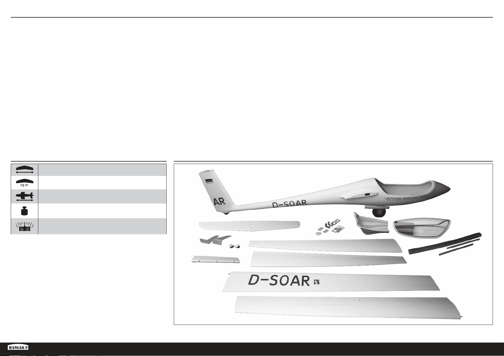
TABLE OF CONTENTS
Notice ......................................................................................................................................................................2
Meaning of Special Language ..................................................................................................................................2
Safety Warnings and Precautions .............................................................................................................................2
Safe Operating Recommendations ........................................................................................................................... 2
Before Starting Assembly ......................................................................................................................................... 2
FAA INFORMATION ...................................................................................................................................................2
Specifications ..........................................................................................................................................................3
Large Parts Layout ...................................................................................................................................................3
Required for Completion ..........................................................................................................................................4
Optional Parts ..........................................................................................................................................................4
Additional Items Required ........................................................................................................................................4
Tools Required ......................................................................................................................................................... 4
Building Precautions ................................................................................................................................................5
Transportation and Storage ......................................................................................................................................5
Fluorescent Color Care .............................................................................................................................................5
Outer Wing Panels ...................................................................................................................................................5
Inner Wing Panels .................................................................................................................................................... 7
Winglet Installation ................................................................................................................................................10
Rudder Installation .................................................................................................................................................10
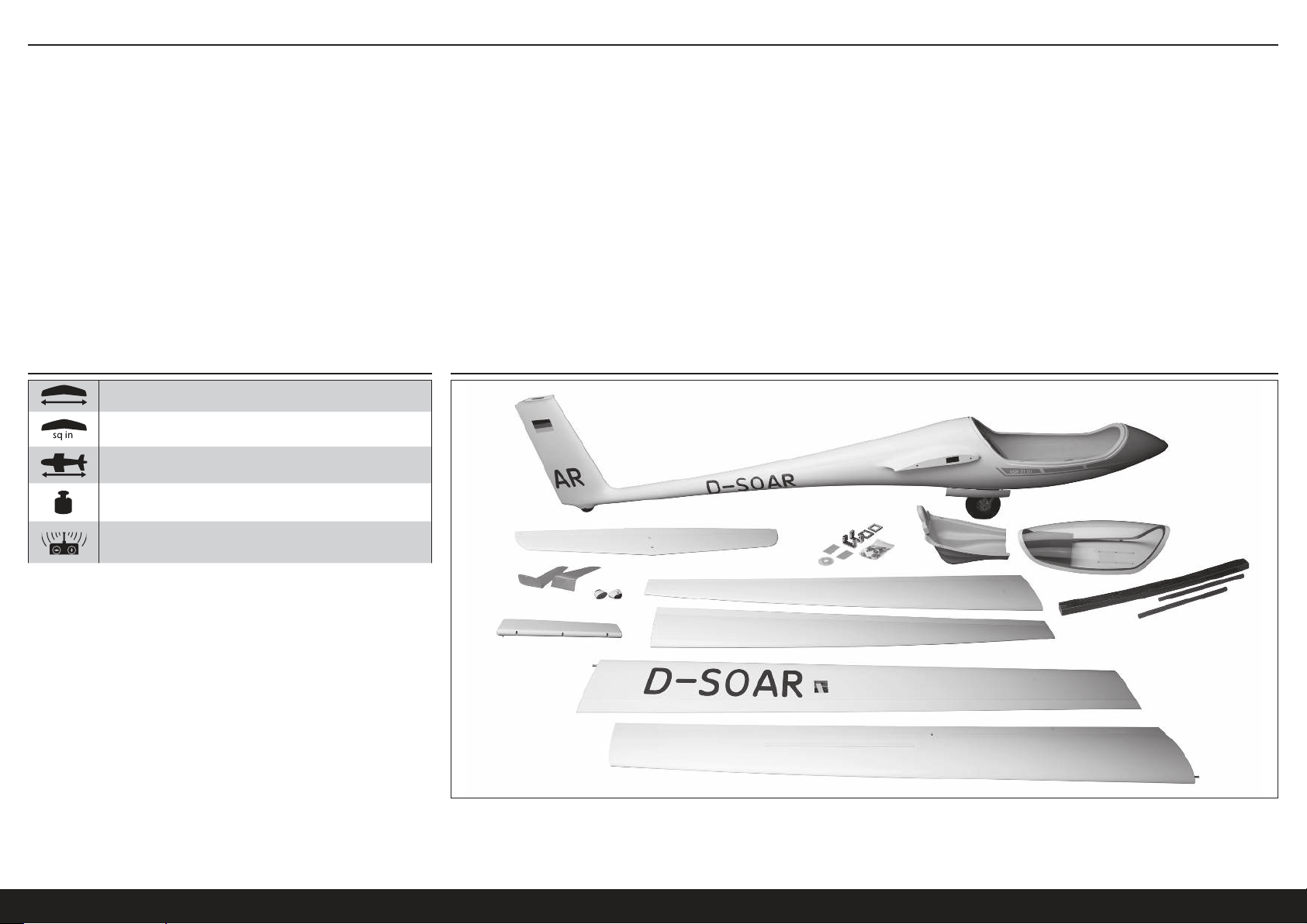
SPECIFICATIONS LARGE PARTS LAYOUT
252 in (6.4m)
1920 sq in (123.87 dm2)
Elevator Installation ...............................................................................................................................................12
Tow Release Installation.........................................................................................................................................13
Radio Installation ...................................................................................................................................................13
Cockpit Installation ................................................................................................................................................14
Optional Electric Power System Installation ............................................................................................................14
Final Assembly .......................................................................................................................................................17
Balancing the Aircraft.............................................................................................................................................18
Control Throws ......................................................................................................................................................19
Preflight Checklist ..................................................................................................................................................19
Daily Flight Checks ................................................................................................................................................19
Limited Warranty ...................................................................................................................................................19
Warranty and Service Contact Information .............................................................................................................20
Compliance Information for the European Union .....................................................................................................20
Instructions for Disposal of WEEE by Users in the European Union ..........................................................................20
AMA National Model Aircraft Safety Code ..............................................................................................................21
Replacement Parts .................................................................................................................................................22
Recommended Parts ..............................................................................................................................................22
Optional Parts ........................................................................................................................................................22
88 in (2.2m)
26 lbs (11.8 kg)
6-channel (or greater) with 7 servos
ASH 31 6.4M ARF
3 EN
Page 4
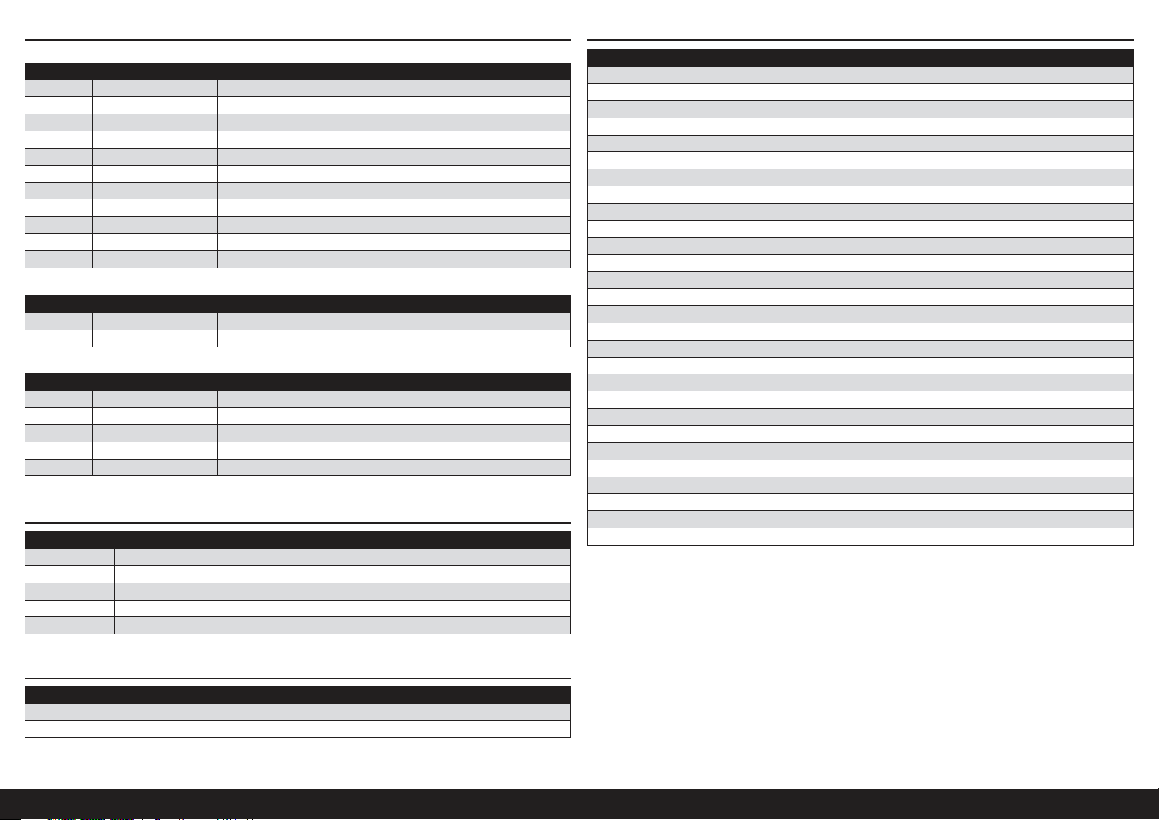
REQUIRED FOR COMPLETION
All Versions
# Required Part # Description
1 SPMAR12310T AR12310T 12CH PowerSafe Tele RX
4 SPMSA5060 A5060 H-T / H-S Mini Metal HV Servo
2 SPMSA7050 A7050 HV Thin Wing Hi Torq MG
3 SPMA3003 Heavy-Duty Servo Extension 12-inch
8 SPMA3004 Heavy-Duty Servo Extension 18-inch
5 SPMA3005 Heavy-Duty Servo Extension 24-inch
4 SPMA3007 Heavy-Duty Servo Extension 48-inch
1 SPMA3008 Heavy-Duty Y-Harness 6-inch
2 SPMB4000LPRX 4000mAh 2S 7.4V LiPo Rx Battery
1 SPMA3054 Servo Connector Clips (25)
1 SPMVR5203 VR5203 Dual Output Regulator
Unpowered, Tow-Launched Version
# Required Part # Description
1 SPMSA7040 A7040 HV Retract Servo
DLMBD38 Liquid Gravity; Weight System
Electric Powered Version
# Required Part # Description
1 CSE010009700 Talon 90 Heli ESC 010-0097-00
1 EFLM4060B Power 60 BLOutrunner Mtr, 470Kv
1 EFLP16080FA Spinner, 45mm: ASW 20 4.7m
1 HAN495512 Propeller 16 x 10: ASW 20 4.7m
1 KXSB40006S40 F-Tek 4000mAh 6S 40C, EC5, LED
OPTIONAL PARTS
Part # Description
SPMA3008 Heavy-Duty Y-Harness 6 inch
SPMAS3000 AS3000 AS3X Stabilization Module
TAM85013 Spray Lacquer TS-13 Clear
TAM86024 PS-24 Fluor Org 100ml Spray Can
TAM87044 Primer White 180ml
TOOLS REQUIRED
Description
Balancing stand
Box wrench: 17mm
Clamps
Clear tape
Crimping tool
Cyanoacrylate (CA) glue, thin and medium
Drill with various size bits
Epoxy
Epoxy brushes
Felt-tipped pen
Isopropyl alcohol
Hemostat
Hex drivers, metric, various sizes
Hobby knife
Long plastic pushrod
Low-tack masking tape
Medium grit sandpaper
Metric ruler
Microballoons
Mixing cups and sticks
Paper towels
Pencil
Phillips screwdriver: #1, #2
Pin vise
Pliers
Rotary tool with cutting disk, drum sander, carbide cutter, grinding stone
Soldering iron and solder
String
ADDITIONAL ITEMS REQUIRED
6+ channel transmitter
LiPo battery charger
Description
4EN
Page 5
BUILDING PRECAUTIONS
Prepare the work surface prior to beginning the build. The surface
should be soft and free of any sharp objects. We recommend resting
the airframe parts on a soft towel or pit mat to prevent scratching or
denting the surface of the aircraft.
TRANSPORTATION AND STORAGE
When transporting and storing your model, you will need a minimum
of 80 inches (2m) in length, and 18 inches (46cm) in height to
accommodate the size of the fuselage. We also recommend the use of
wing and stabilizer bags to help protect these surfaces during transport
and storage. The control horns and linkages can cause damage to
other surfaces even when placed in storage bags. Always transport
and store the wings and stabilizer so the linkages do not contact other
panels to prevent damage.
FLUORESCENT COLOR CARE
The fluorescent color used on your model can fade with exposure to
direct sunlight over time. To increase the longevity of the fluorescent
color on the aircraft, limit the exposure to direct sunlight when not flying.
If repairs become necessary or if you decide to color optional parts
to match the fuselage color, Tamiya spray color, PS-24, Fluorescent
Orange is a close match to the color used on the model. For best
results, PS-24 needs to be sprayed over Tamiya Fine White Primer
(TAM87044) and clearcoated with Tamiya TS-13, Clear.
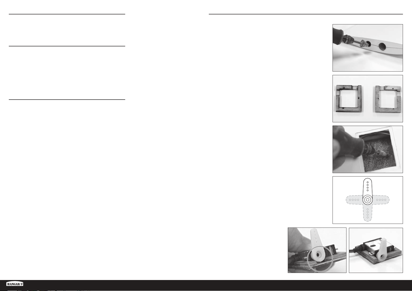
OUTER WING PANELS
1. Remove packing tape, clean and polish the wing surface.
2. Cut an access hole in the root end of the outer wing panel using a
rotary tool.
TIP: Make the hole just large enough for the servo connector to fit
through. If the hole is too big, the extension will fall back into the
wing panel when disconnected.
3. Find the short servo mounts. Drill pilot holes for the servo mounting
screws.
4. Carefully roughen the wing servo mounting surface for the servo
mount using either a rotary tool on low speed or 80 grit sandpaper.
Only lightly scuff the inner surface of the wing panel to give the
epoxy something to grip. DO NOT sand through the surface of the
wing panel. Clean the mounting surface thoroughly with denatured
alcohol or 91% IPA.
ASH 31 6.4M ARF
5. Cut 3 arms from a 4 arm servo horn.
6. Test fit the servo with the servo arm
installed. Enlarge the opening in the mount
as necessary to allow the servo to sit fully
in the mount.
Test fit the servo mount screws as well to
ensure they do not protrude through the
mount and damage the wing surface. If
the screws protrude, cut them off so they
are below the surface of the mount.
5 EN
Page 6
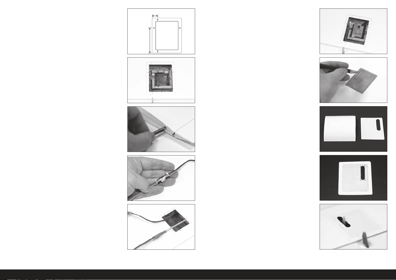
7. Measure and mark the wing panel at the servo hatch; 10mm from
raised outer hatch edge and 45mm from rear raised edge.
When mounting the frame in the wing, the edge of the frame lines
up with the front and back marks, and the servo output lines up
with the 45mm mark.
45mm
10mm
12. Install the servo arm. Install the servo in the mount using short
servo screws (2 x 8mm).
8. Using epoxy (DLMAD64), install the servo mount to the wing panel.
Ensure the servo arm will align with the surface control horn.
The arm clearance notch should face the wingtip and the servo
lead notch should face forward. Clean any epoxy from the servo
mounting area, which may interfere with the servo fitting into the
mount, with paper towel and alcohol. Allow the epoxy to cure fully.
9. Install anti-rotation pins in the root end with epoxy. Do not push the
pin in past half the length of the pin. Wipe away any excess epoxy
with paper towel and alcohol.
10. Connect a 12” servo lead extension to the aileron servo. Secure the
extension with a servo connector clip (SPMA3054) or heat shrink
tubing.
13. Carefully measure and cut the hole in the hatch for the servo arm
using a rotary tool or hobby knife. Test fit the hatch often to ensure
adequate clearance of the servo arm through full travel of the
servo. Round the outside corners of the hatch to fully fit into the
recessed mounting area of the wing panel.
14. Cut a piece of white UltraTrim (HANU80000) adhesive film about
3cm larger than the size of the servo hatch.
15. Peel and stick the adhesive film to the finished side of the servo hatch.
TIP: Start at the center of the hatch and carefully press any air
bubbles and wrinkles out of the film as you work your way to the
edges.
Cut and remove the hole for the servo arm. Trim the film to
approximately 10mm past the edge of the hatch and ease the
corners as shown to help prevent the corners from lifting after use.
11. Use either a string with a weight attached or a long plastic pushrod
to thread the assembled servo extension through the wing panel
and out the previously cut access hole.
TIP: Feed the string or plastic rod through the access hole to the
servo hatch and attach the servo lead to the end. Pull the servo
lead end back through the access hole.
16. Carefully install the servo hatch to the wing panel by placing the
hatch in the recess of the wing panel and pressing the film to the
wing panel around the perimeter of the hatch. Work outward from
the hatch to remove any air bubbles or wrinkles.
6EN
Page 7

17. With the aileron held at center, measure between the holes of the
servo arm and the control horn.
18. Set the length of the aileron pushrod to the measurement above by
turning in or out on the clevis at either end of the pushrod. When
the correct length is achieved, apply thread locking compound and
tighten the nuts against the clevis. Try to center the threaded rod
between the two clevises.
TIP: The excess threaded rod may be cut off, if desired. Leave
enough of the rod that at least 3 threads are visible on the inside of
the clevis, as shown.
19. Install the pushrod to the servo and control surface horns. Ensure
the control surface is centered when the servo is at neutral.
INNER WING PANELS
1. Remove packing tape, clean and polish the wing surface.
2. Lay the finished outer wing panel next to the inner wing panel as
shown. Mark the location of the outer wing access hole on the
inner wing panel.
3. Cut access holes in both the outer and root ends of the inner
wing panel. The holes should be just large enough to fit the servo
connectors through to keep the ends from falling back into the
wing.
4. Connect a 48” and 24” servo extension together to create an inner
aileron extension. Secure with a clip or heat shrink tubing.
20. Repeat steps 1–19 for the opposite outer wing panel.
ASH 31 6.4M ARF
5. Insert a long plastic pushrod or weighted string through the cut
access hole in either end of the panel and out the flap servo hatch.
Attach one end of the assembled aileron servo extension to the
pushrod. Pull the extension end through the wing panel and out the
access hole. Tape the extension end to the end of the wing panel.
Repeat the procedure from the other end of the panel to pull the
opposite end of the aileron servo extension through the access
hole in the other end of the wing panel.
7 EN
Page 8
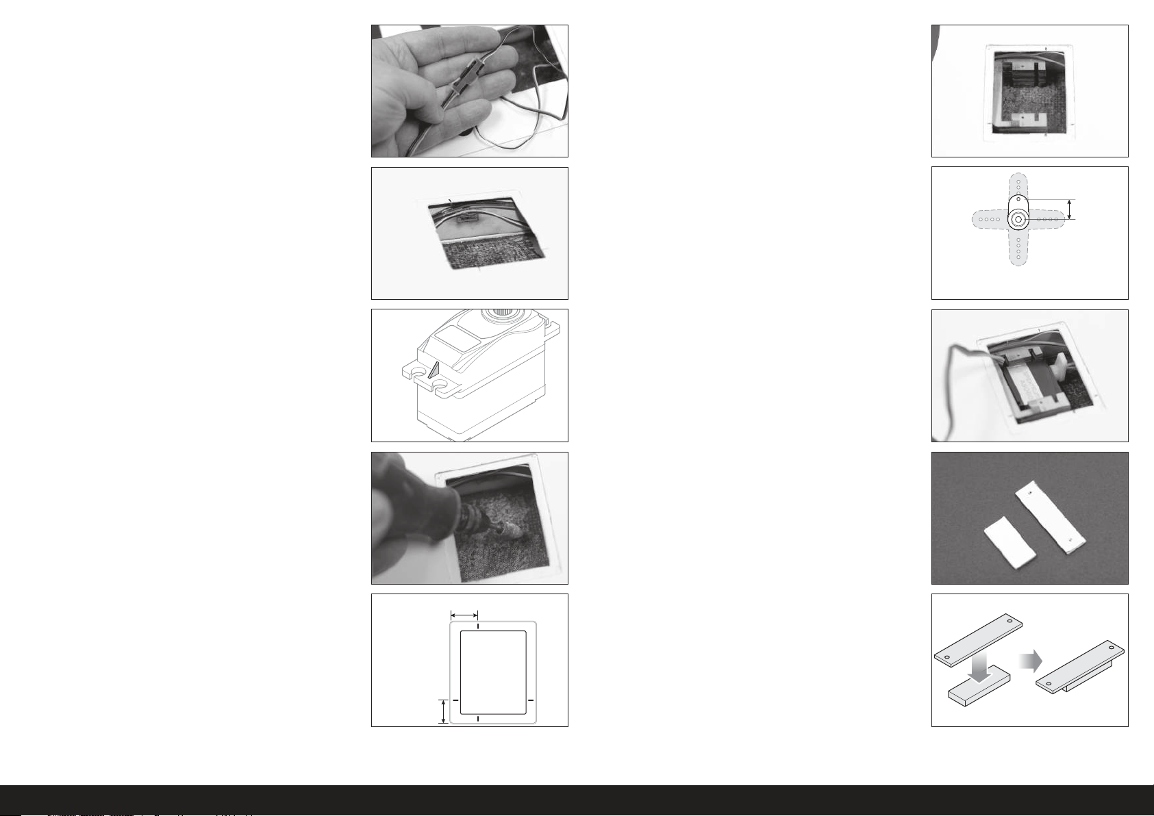
10mm
6. Connect an 18” servo extension to the spoiler lead and secure it
with a clip or heat shrink tubing. Thread the extension through the
inner end of the wing panel as before.
11. Install the flap servo mount using epoxy. Align the mount with the
marks made in the previous step. Remove any epoxy that squeezes
into the mounting lug slots or the inner base of the mount which
may interfere with the servo. Ensure the mount bonds to the wing
spar as well as the surface and that the servo arm will align with
the flap control horn. Allow epoxy to fully cure.
7. Using hot glue or contact adhesive, such as Deluxe Systems
Foam2Foam (DLMAD34), secure the aileron and spoiler leads to
the spar at the front of the servo hatch. Doing so will keep the leads
from shifting and interfering with the flap servo arm and pushrod.
8. Carefully trim the webs from the servo mounting lugs. Test fit the
servo in the servo mount. The servo should be a very snug fit in the
mount.
9. Carefully scuff the wing flap servo mounting surface for the servo
mount using either a rotary tool on low speed or 80 grit sandpaper.
Only lightly scuff the inner surface of the wing panel to give the
epoxy something to grip. DO NOT sand through the surface of the
wing panel. Clean the mounting surface thoroughly with denatured
alcohol or IPA.
12. Cut the flap servo arm to length.
13. Center the servo and install the control horn angled slightly toward
the trailing edge of the wing.
14. Slide the servo into the mount as shown.
15. Using the acetate template provided, create a servo retention plate
using 1/8” and 1/16” ply.
10. Measure and mark the flap servo hatch opening, 12mm from the
rear recess line and 17mm from the outer recess line, as shown in
the illustration.
17mm
12mm
8EN
Page 9
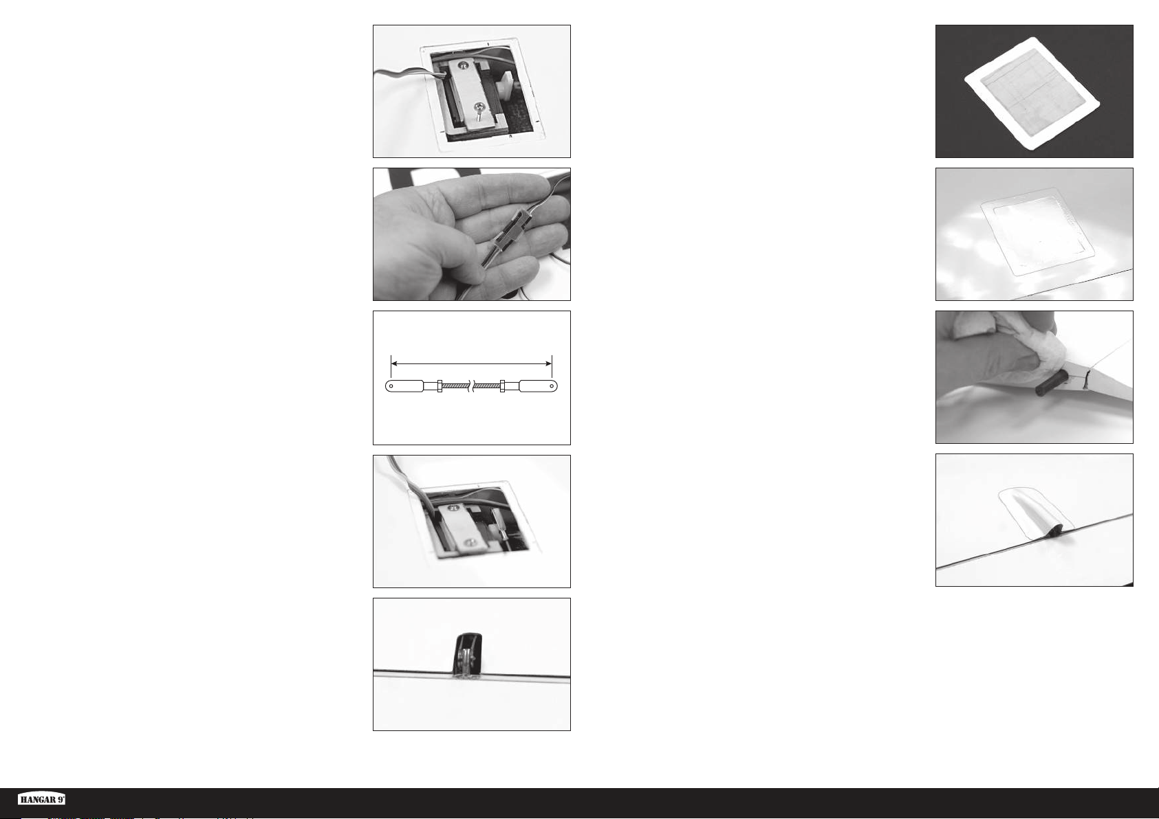
79mm
16. Secure the servo in the mount with the servo retention plate and
two screws. Ensure the screw heads sit below the servo hatch
mounting surface and the screws don’t damage the outer surface
of the wing panel.
17. Connect a 24” servo extension to the servo lead and secure with
a clip or heat shrink tubing. Thread the extension through the
wing root end of the wing panel, using a long plastic pushrod or
weighted string as before.
20. Install the servo hatch to the wing with tape as done on the outer
wing panel.
18. Cut the pushrods to 79mm length.
19. Install the pushrod to the flap horn and servo arm. Deflect the flap
down and insert one end of the pushrod through the hole in the
trailing edge of the wing and connect it to the servo arm. Connect
the other end of the pushrod to the flap control horn.
21. Install anti-rotation pins in the root end of the panel with epoxy.
Wipe away any excess epoxy with paper towel and alcohol.
22. Trim and attach the flap pushrod exit cover to the top of the wing
using contact cement.
23. Repeat steps 1–22 for the opposite inner wing panel.
ASH 31 6.4M ARF
9 EN
Page 10
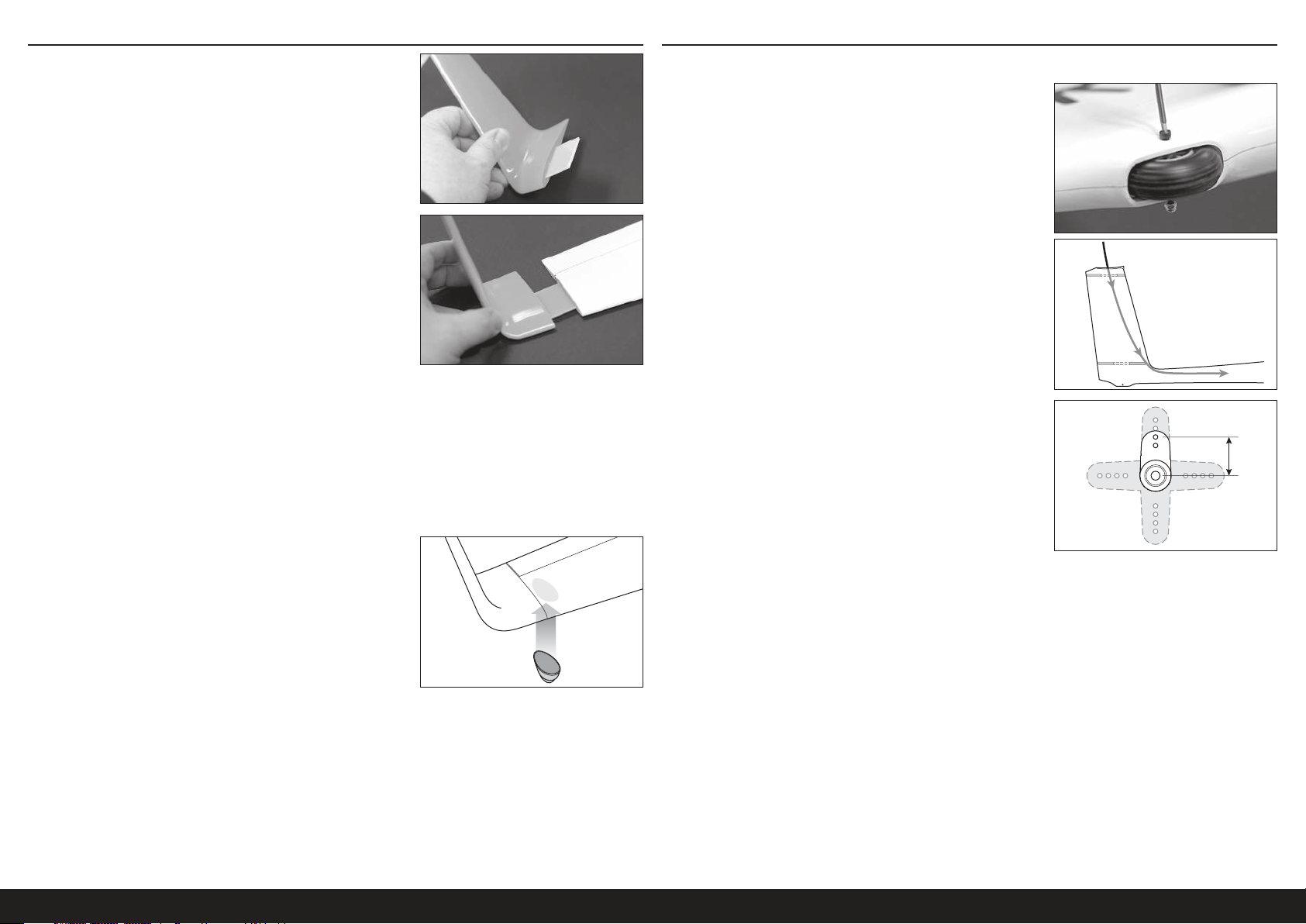
13mm
WINGLET INSTALLATION
1. Slide the winglet blade into the winglet slot.
2. Slide the assembly into the slot in the outer wing panel tip.
RUDDER INSTALLATION
1. Clean and polish the fuselage.
2. Remove the tailwheel using a 2.5mm hex driver.
3. Feed a weighted string or long flexible pushrod through the elevator
servo opening, through the vertical fin, through the small hole in
front of the rudder servo opening and up through the fuselage
tail. This will be used later to pull the rudder and elevator servo
extensions through the fuselage.
3. Trim the winglet blade to length, if necessary, to achieve a tight fit
of the winglet against the wing panel. There should not be a gap
between the panel and the winglet.
4. The blade should be a tight fit in both the winglet and the outer
wing panel. The winglet should be taped in place for added
security.
5. Using epoxy, attach a wing tip wheel to the outer wing panel
bottom, near the tip.
TIP: Use fine grit sandpaper or a scouring pad to very lightly scuff
the surface of the wing panel where the wheel will be attached to
give the epoxy something to grip.
Repeat steps 1-5 for the opposite wingtip.
4. Trim a servo arm to 13mm.
5. Center the rudder servo and install the servo arm.
6. A 60” servo extension is required for the rudder servo. Connect a
48” and a 12” extension to the rudder servo. Secure all connections
with servo extension clips or heat shrink tubing.
10EN
Page 11
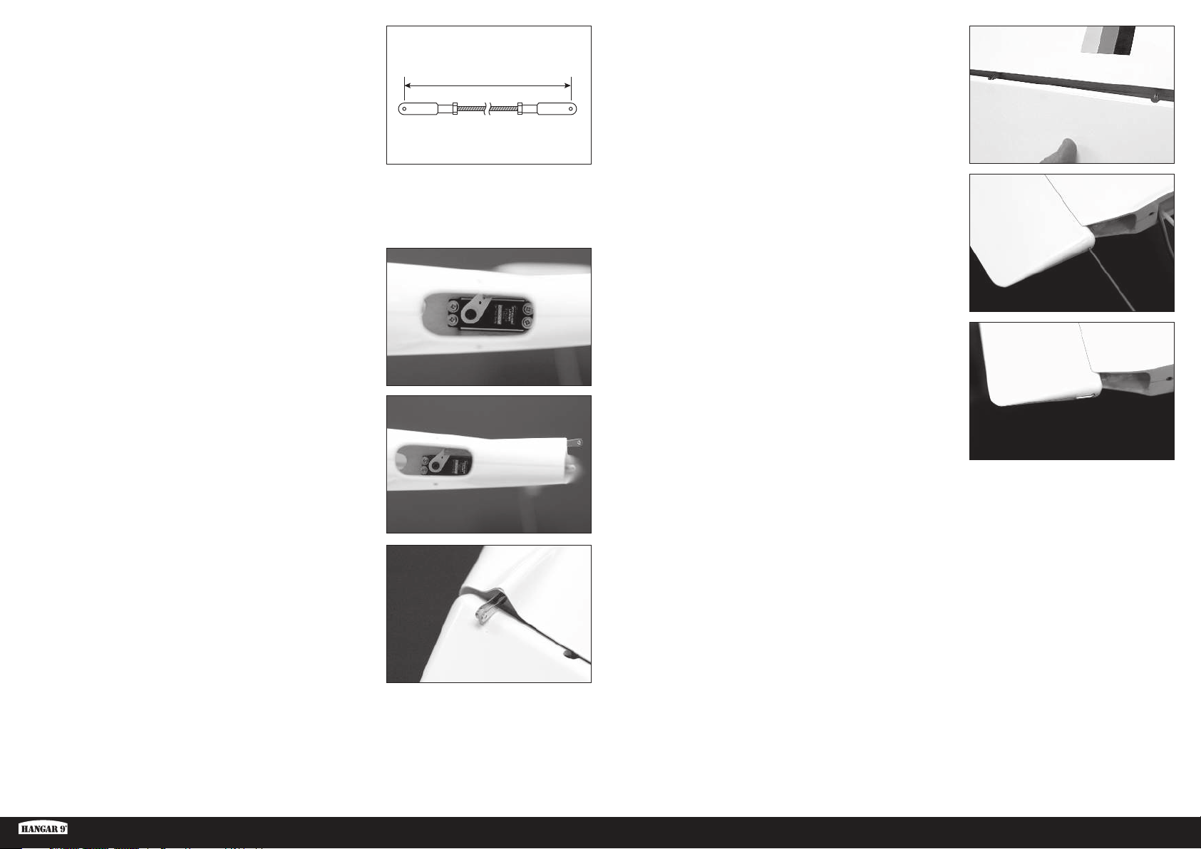
95mm
7. Trim the rudder pushrod so the finished length is 95mm between
the clevis pins. Attach one end of the pushrod to the rudder servo
arm.
12. Push the rudder over the hinge points in the fin.
8. With the fuselage upside down in a stand, feed the servo extension
through the rudder servo cutout and out the elevator servo cutout at
the top of the fin. This extension will be pulled through the fuselage
with the elevator servo extension later.
9. Install the rudder servo through the tailwheel opening and into the
servo mount. The servo is installed with the output shaft toward
the front of the aircraft and the servo arm toward the left side of
the fuselage. Feed the open end of the pushrod through the molded
opening in the tail as you fit the servo into place. Keep some tension
on the servo lead to ensure the lead is not pinched in the opening.
TIP: Use a magnetic screwdriver or attach a small magnet to a
regular screwdriver to install the servo screws.
10. Rotate the servo horn so the pushrod extends out the back of the fin.
11. Attach the rudder control horn to the pushrod.
13. Carefully insert the rudder hinge pin through the hole in the top of
the rudder and feed it fully through each of the hinge points until it
exits through the bottom of the rudder.
TIP: The hinge pin is a tight friction fit. It may be necessary to lightly
push or pull on the rudder as the pin is inserted to get the pin to
seat fully. Do not force the pin through. If you feel resistance, move
the rudder slightly and continue to insert the pin.
14. When fully inserted, the hinge pin may be taped at the top of the
rudder if desired or if the hinge pin is excessively loose.
ASH 31 6.4M ARF
11 EN
Page 12
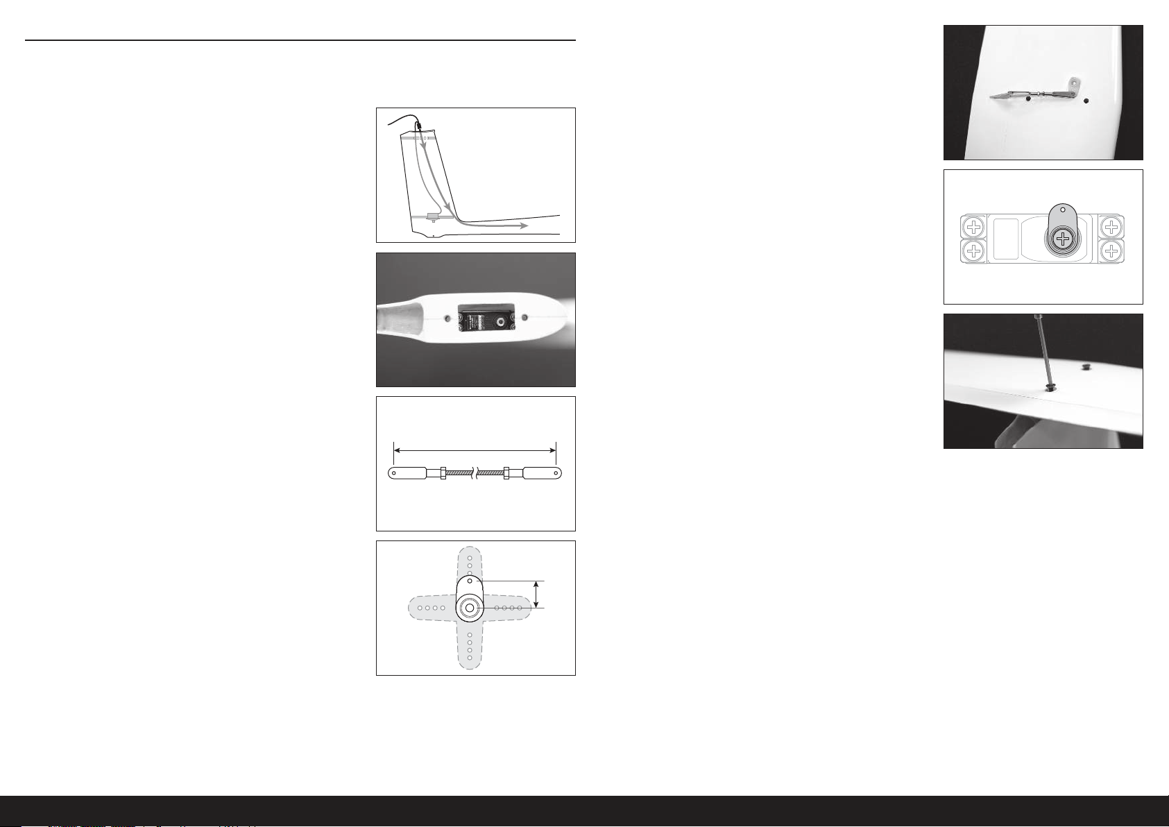
53mm
10mm
ELEVATOR INSTALLATION
1. A 72” servo extension is required for the elevator servo. Connect
a 48” and a 24” extension together and connect to the elevator
servo. Secure all connections with clips or heat shrink tubing.
2. Tape the ends of the rudder and elevator servo extensions to
the end of the flexible pushrod or string that was inserted in the
fuselage earlier. Carefully pull the servo extensions through the
fuselage and up to the cockpit.
3. Fit the elevator servo into place with the output shaft toward the
front of the aircraft. Ensure the servo lead is not pinched.
4. Trim the elevator pushrod so the finished length is 53mm between
the clevis pins. The clevises should be at 90° to each other.
6. Attach one end of the pushrod to the elevator servo arm and the
other end to the elevator control horn.
7. Feed the elevator pushrod with the servo arm attached through the
top of the fin. Center the elevator servo. Attach the servo horn to
the servo output shaft at 90° as shown in the illustration.
8. Attach the horizontal stab to the fin using two M4 X 20mm flathead
screws.
5. Trim the elevator servo arm to 10mm.
12EN
Page 13
TOW RELEASE INSTALLATION RADIO INSTALLATION
IMPORTANT: If you are installing the electric power option, skip this
section and see the optional electric power installation secton.
1. Install the tow release wire to the servo arm.
2. Install the tow release servo into the nose of the fuselage. Slide
the release wire through the small hole in the front of the cockpit.
Attach the arm to the servo, ensuring the wire fully opens at one end
of the servo travel and fully closes at the opposite end of travel.
IMPORTANT: While the spoilers and retract will operate on 7.2V, for increased longevity and reliability, we recommend
regulating the power input of these components to 5.2V with the use of an inline voltage regulator, such as SPMVR5203.
If the retract is slow to operate or does not retract to the fully locked position at the regulated voltage, run the retract
directly to the receiver at 7.2V.
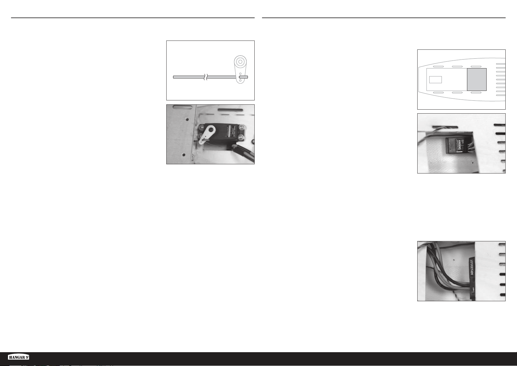
1. Carefully cut the rear of the cockpit floor in the area shown.
2. Connect the gear and spoiler channels from the receiver to the
input ports of the regulator.
3. Connect the output ports of the regulator to the gear lead and the
spoiler y-harness.
4. Route all servo leads from the tail to the forward fuselage, keeping
them as organized as possible. Use wire ties or hook and loop tape
to secure the leads in the fuselage.
ASH 31 6.4M ARF
5. Prepare six 18-inch servo leads; two for ailerons, two for flaps and
two for spoilers.
TIP: Use different colored tape wrapped around the ends of the
leads to differentiate which leads go to which control surface.
6. Connect all servo leads to the appropriate receiver ports.
7. Mount the receiver under the rear of the cockpit floor as shown. If
necessary, use small pieces of foam or hook and loop tape to hold
the receiver in place.
TIP: If desired, cut holes in the rear of the cockpit floor and route
the servo leads to the receiver.
8. Temporarily mount the receiver batteries as far forward in the
cockpit as possible. The battery location will be finalized after the
correct center of gravity has been established. The unpowered, glider version will have the batteries mounted as
far forward as possible, along with additional nose weight.
The electric powered version does not require additional nose weight to balance, and depending on the motor
battery used, may require the receiver batteries to be moved rearward.
13 EN
Page 14

COCKPIT INSTALLATION
1. Install the fiberglass cockpit tub. Squeeze gently on the sides of
the tub to fit it between and under the molded fuselage sides.
The holes in the tub should line up with the holes in the fuselage.
It is not necessary to secure the tub to the fuselage. The tub is
removable to allow for access to the rear of the fuselage and the
lower cockpit area.
OPTIONAL ELECTRIC POWER SYSTEM INSTALLATION
1. Roughen one side of each of the motor mount pieces using 80 grit
sandpaper.
2. Install an optional pilot into the tub for added scale realism if
desired. It is not necessary to secure the pilot to the tub.
TIP: Hangar 9 has partnered with two companies who offer
custom pilots; www.warbirdpilots.com in the United States and
www.tailoredpilots.com in the United Kingdom offer very detailed
pilot figures to suit the ASH 31.
3. Install the canopy to the fuselage by inserting the pin at the front
of the canopy into the hole at the front of the fuselage and rotating
the back of the canopy down against the fuselage, ensuring the
side alignment lugs insert into the holes in the fuselage.
2. Using 5-minute epoxy, glue the roughened sides of the two motor
mount pieces together, ensuring the holes line up accurately. Clean
up any excess epoxy with alcohol and a paper towel. Clamp the
pieces together until the epoxy fully cures.
3. Trace a line around one side of the mount approximately 1.5mm
from the outer edge, as shown.
4. Using the line as a guide, sand a bevel on the edge of the mount by
sanding across the edge, from the back corner to the line.
4. Slide the wire canopy lock, located under the left wing root, in until
the canopy is secured. It may be necessary to press gently on the
back of the canopy to get it to latch fully. The wire lock is purposely
a tight fit to prevent coming loose in flight.
5. Using 1/8” tape, mark a line 25mm back from the nose of the
fuselage.
14EN
Page 15
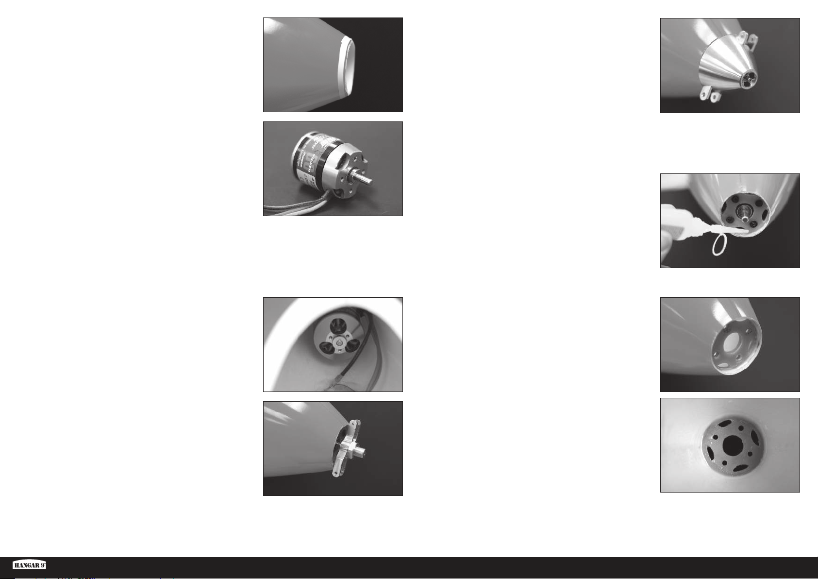
6. Carefully cut the nose away from the fuselage using a rotary tool
with a cutoff disk. Do not cut all the way to the tape. Leave some
excess to be sanded away later.
11. Press the motor forward and tighten the spinner center screw
while pressing against the motor. Tighten the screw just enough
to hold the motor in place but still allow for adjusting the spinner
placement against the fuselage.
12. Use the spinner to correctly align the motor with the nose of the
fuselage.
7. Following the instructions included with the motor, change the
motor shaft orientation for mounting the motor to the back of the
mount.
8. Attach the motor mount to the motor using screws provided with
the motor. If necessary, use a countersink to bevel the holes in
the mounting plate. Ensure the narrow side of the edge bevel
previously sanded into the mount is facing away from the motor.
9. Insert the motor and mount into the nose of the fuselage from the
inside.
10. Press the propeller adapter onto the motor shaft and loosely install
the propeller nut. Install the spinner over the propeller adapter.
Ensure the spinner is fully seated over the adapter. Install the
spinner center screw.
13. When the alignment is correct, hold the motor steady from the
inside of the fuselage and carefully remove the spinner assembly
by loosening the spinner center screw, being careful to not move
the motor. Slide the spinner assembly off of the motor shaft.
14. With the spinner removed, temporarily tack the motor mount to the
fuselage with a couple drops of medium CA and accelerator around
the mounting ring.
15. Remove the motor mount screws and remove the motor, being
careful not to break the motor mount loose from the fuselage.
16. DO NOT SKIP THIS STEP. Apply a generous bead of epoxy around
the joint between the mount and fuselage, both in front of and
behind the motor mount. Press the epoxy into the joint and smooth
it to form a fillet. Allow the epoxy to fully cure before continuing.
ASH 31 6.4M ARF
15 EN
Page 16
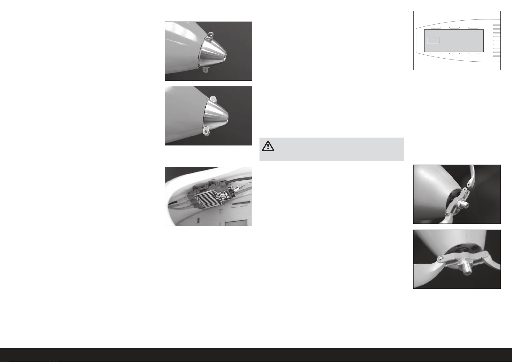
17. Temporarily install the motor and spinner assembly.
18. Measure and mark 1mm back from the spinner around the
fuselage.
19. Remove the spinner assembly and motor and sand the front of the
fuselage back to the line.
TIP: Use a sanding block to keep the front of the fuselage straight.
Remove material slowly and check the progress often. The goal is
to get a perfectly straight line that is parallel with the back of the
spinner around the circumference of the fuselage.
20. Mount the motor to the motor mount using medium thread locking
compound.
24. Cut and remove the section of the cockpit floor shown.
25. Mount the motor battery in the cockpit floor and secure using hook
and loop straps through the pre-cut holes in the cockpit floor.
26. Mount the receiver batteries at the rear of the cockpit. The receiver
batteries can be moved accordingly to adjust the balance of the
aircraft. When using the recommended optional power system
components no additional ballast should be required. However,
proceed to the Balancing the Aircraft section to confirm the correct
center of gravity.
CAUTION: Never attempt to fly without properly balancing the
aircraft. An un-balanced aircraft will be extremely unstable and
may cause a crash. Crash damage is not covered under warranty.
21. Use hook and loop tape or servo tape to install the ESC in the
cockpit.
22. Connect the motor leads to the ESC following the instructions
included with the motor and ESC.
23. Connect the ESC throttle lead to the appropriate reciever port.
27. Prepare the spinner yoke by installing the tapered shaft and nut.
Do not tighten the nut at this time.
28. Check the fit of the propeller blades to the yoke. The blade should
move freely when the pin is installed. If not, lightly sand the blades
where they contact the yoke to allow free movement.
29. Once the blades fit the yoke, use the pins and clips to secure the
blades to the yoke. Ensure the front of the blades are facing toward
the notched side of the yoke.
30. Fit the assembly to the motor shaft. Check that the yoke can rotate
freely and not contact the front of the fuselage through its full
rotation. Use a 12mm wrench to tighten the nut, securing the yoke
and adapter.
31. Install the spinner, making sure it fits into the notches in the
propeller yoke. Use the screw provided with the spinner and a
#1Phillips screwdriver to secure the spinner to the adapter.
TIP: The spinner and propeller blades may be painted to match
the fluorescent orange of the aircraft nose, using the products
mentioned in the Fluorescent Color Care section, making the
spinner and propeller almost invisible during flight.
16EN
Page 17
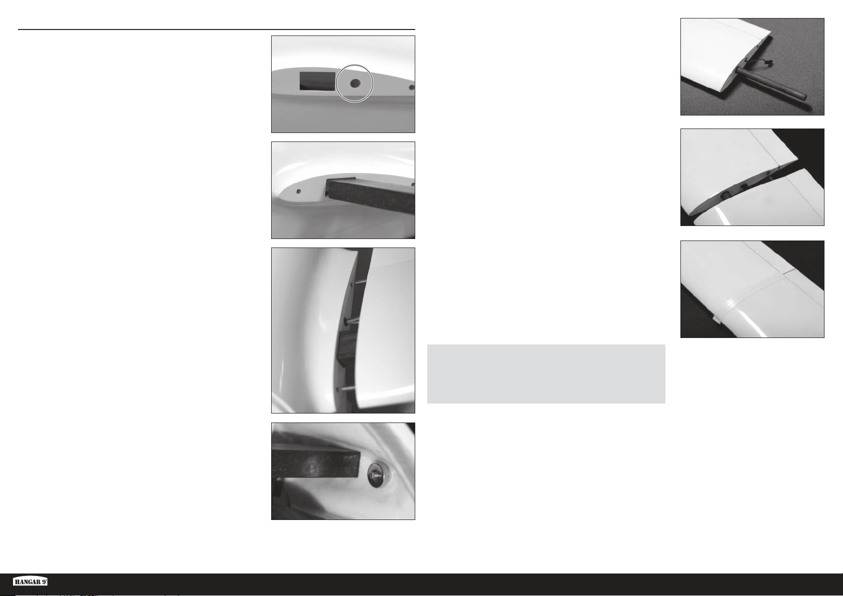
FINAL ASSEMBLY
1. Cut a hole in the wing root of the fuselage for the various servo leads
from the wing. Ensure the hole aligns with the hole previously cut in
the root of the inner wing panel and it is large enough to allow the
servo lead connectors to pass through. Use sandpaper to remove
any sharp edges around the hole.
2. Insert the wing joiner into the fuselage. The joiner should be a snug
fit in the fuselage opening. Ensure the joiner is centered in the
fuselage.
5. Slide an outer wing tube into the outer end of the inner wing panel.
6. Slide the outer wing panels over the wingtube until the outer panel
contacts the inner panel. Ensure the wing alignment pin is inserted
into the wing alignment hole.
3. Slide the inner wing panels over the ends of the wing joiner,
connecting the servo leads and inserting the wing alignment pin in
the fuselage as you slide the panel on.
4. Thread the wing retention nut onto the threaded wing stud from
the inside of the fuselage. Hand tighten the retention nut, ensuring
the various servo leads are not pinched between the wing and the
fuselage.
7. Wrap the seam between the inner and outer panel with tape. Ensure
the tape does not interfere with the operation of the wing control
surfaces. White PVC electrical tape is recommended. We have found
this tape to be more than sufficient to retain the outer wing panels in
flight, even during aggressive aerobatic maneuvers.
NOTICE: Always ensure the wing is clean, dry and free from any dust or
debris prior to installing the tape.
NOTICE: Do not re-use the tape after disassembling the wing. Use new
tape every time the wing is reassembled.
8. Install the tip winglet as described in the Winglet Installation section.
9. Repeat steps 1-8 for the opposite wing.
10. Install the cockpit shell, pilot and canopy to the fuselage.
ASH 31 6.4M ARF
17 EN
Page 18

BALANCING THE AIRCRAFT
CAUTION: DO NOT SKIP THIS STEP. Never attempt to fly
without properly balancing the aircraft. An un-balanced aircraft
will be extremely unstable and may cause a crash. Crash damage is
not covered under warranty.
Add ballast to the nose of the aircraft until the fuselage sits level
or slightly nose-down on the balancing stand.
TIP: Tape a plastic bag to the outside of the nose of the fuselage
and add weight, such as lead shot or Deluxe Materials Liquid
Gravity (DLMBD38) to the bag until the aircraft balances.
1. Attach the wing panels, canopy and tail surfaces to the fuselage.
Make sure to connect the leads from the aileron, flaps and spoilers
to the appropriate leads from the receiver. Make sure the leads are
not exposed outside the fuselage before tightening the wing bolts.
Your model should be powered OFF, in an otherwise flight-ready
state prior to balancing.
2. The recommended center of gravity (CG) location for your model
3
/8–35/16 inches (60–85 mm) back from the leading edge of
is 2
the wing at the root. Mark the CG location on the wings with tape
or a marker. Balance your model upright with your fingers or a
balancing stand supporting the model at the marks made on the
bottom of the wing.
3. Support the aircraft upright at the marks made on the wing with
your fingers or a commercially available balancing stand.
If you are building the unpowered, tow launch version, proceed to
step 5.
23/8–35/16 inches
(60–85 mm)
5. Remove the wings, canopy and flight batteries from the fuselage,
and carefully stand the fuselage up on its nose.
6. Mix the ballast from step 5 with epoxy and micro balloons and add to
the inside of the nose of the fuselage. Allow the mixture to fully cure.
TIP: An alternative to adding the ballast directly to the fuselage
is to use the spinner from the Hangar 9 RV-4 (HAN488509) as a
mold to hold the epoxy/ballast mixture until it cures. This spinner
is an almost perfect match to the shape of the ASH nose. Pour the
ballast mixture into the spinner. After fully curing, the mixture can
be removed from the spinner and securely mounted in the nose of
the fuselage with epoxy.
Return the flight batteries to their position in the cockpit and
secure their location.
4. If you are building the electric powered version, move the receiver
batteries forward or backward in the cockpit until the aircraft sits
level or slightly nose down on the balancing stand. When the proper
center of gravity is achieved, mount the receiver batteries to the
fuselage using hook and loop tape.
Proceed to the Control Throws section.
TIP: If the proper balance point cannot be achieved with the receiver
batteries fully forward, add self-adhesive weight until the aircraft
balances.
18EN
Page 19
CONTROL THROWS
1. Turn on the transmitter and receiver of your model. Check the movement of the rudder using the transmitter.
When the stick is moved to the right, the rudder should also move right. Reverse the direction of the servo at the
transmitter if necessary.
2. Check the movement of the elevator with the radio system. Moving the elevator stick toward the bottom of the
transmitter will make the airplane elevator move up.
3. Check the movement of the ailerons with the radio system. Moving the aileron stick to the right will make the right
aileron move up and the left aileron move down.
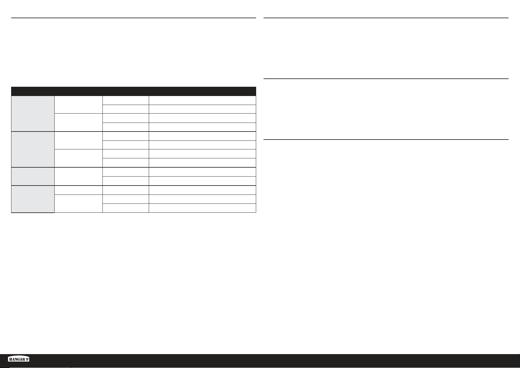
4. Use a ruler to adjust the throw of the elevator, ailerons and rudder.
Surface Rate Direction Throw
Landing/Soaring
Aileron
Cruise/Launch
High
Elevator
Low
Rudder High
Landing Down
Flaperon
Cruise/Launch
• In Landing or Soaring Mode, the ailerons will move independent from the flaperons.
• In Landing or Soaring Mode, droop the entire trailing edge (flaperons and ailerons) down 1/8–5/32 inches (3–4mm).
• In Cruise or Launch Mode, couple the ailerons and flaperons for full roll control.
• In Cruise or Launch Mode, reflex the entire trailing edge (flaperons and ailerons) up 1/8–5/32 inches (3–4mm).
• Use a slider to control the flaperon throw so the amount of travel can be varied.
• We recommend lowering the flaperons 3/8 inches (10mm) during Rise-Off-Ground (ROG) takeoffs and
during aero-tow.
• Set the rudder throw to an amount that will not bind the servo.
• Set the maximum flaperon throw to an amount that will not bind the servo.
Up 5/8 inches (16mm)
Down 15/32 inches (12mm)
Up
11/16–13/16 inches (18–20mm)
Down 17/32 inches (14mm)
Up 11/32 inches (9mm)
Down 9/32 inches (7mm)
Up 9/32 inches (7mm)
Down 3/16 inches (5mm)
Right
Left
Up
1
/8–19/32 inches (35–45mm)
1
1
/8–19/32 inches (35–45mm)
1
3
/16 inches (25–30mm)
1–1
11/16–13/16 inches (18–20mm)
Down 17/32 inches (14mm)
PREFLIGHT CHECKLIST
• Charge the transmitter, receiver and motor batteries. Follow the instructions provided with the charger. Follow all
manufacturer’s instructions for your electronic components.
• Check the radio installation and make sure all control surfaces (aileron, elevator, rudder, flaps and spoilers) move
correctly (i.e., the correct direction and with the recommended throws).
• Check all the hardware (control horns, servo horns, and clevises) to make sure they are secure and in good condition.
• Prior to each flying session (and especially with a new model), perform a range check of your radio system. See your
radio manual for the recommended range and instructions for your particular radio system.
DAILY FLIGHT CHECKS
• Check the battery voltage of the transmitter battery. Do not fly below the manufacturer’s recommended voltage.
Doing so can cause your aircraft to crash.
• Check all hardware (linkages, screws, nuts, and bolts) prior to each day’s flight. Ensure that binding does not occur
and that all parts are properly secured.
• Ensure all surfaces are moving in the proper manner.
• Perform a ground range check before each day’s flying session.
• All servo leads and switch harness plugs should be secured in the receiver.
LIMITED WARRANTY
What this Warranty Covers
Horizon Hobby, LLC, (Horizon) warrants to the original purchaser that the product purchased (the “Product”) will be free from
defects in materials and workmanship at the date of purchase.
What is Not Covered
This warranty is not transferable and does not cover (i) cosmetic damage, (ii) damage due to acts of God, accident, misuse,
abuse, negligence, commercial use, or due to improper use, installation, operation or maintenance, (iii) modification of or to
any part of the Product, (iv) attempted service by anyone other than a Horizon Hobby authorized service center, (v) Product
not purchased from an authorized Horizon dealer, (vi) Product not compliant with applicable technical regulations, or (vii) use
that violates any applicable laws, rules, or regulations.
OTHER THAN THE EXPRESS WARRANTY ABOVE, HORIZON MAKES NO OTHER WARRANTY OR REPRESENTATION,
AND HEREBY DISCLAIMS ANY AND ALL IMPLIED WARRANTIES, INCLUDING, WITHOUT LIMITATION, THE IMPLIED
WARRANTIES OF NON-INFRINGEMENT, MERCHANTABILITY AND FITNESS FOR A PARTICULAR PURPOSE. THE PURCHASER
ACKNOWLEDGES THAT THEY ALONE HAVE DETERMINED THAT THE PRODUCT WILL SUITABLY MEET THE REQUIREMENTS
OF THE PURCHASER’S INTENDED USE.
Purchaser’s Remedy
Horizon’s sole obligation and purchaser’s sole and exclusive remedy shall be that Horizon will, at its option, either (i) service,
or (ii) replace, any Product determined by Horizon to be defective. Horizon reserves the right to inspect any and all Product(s)
involved in a warranty claim. Service or replacement decisions are at the sole discretion of Horizon. Proof of purchase is
required for all warranty claims. SERVICE OR REPLACEMENT AS PROVIDED UNDER THIS WARRANTY IS THE PURCHASER’S
SOLE AND EXCLUSIVE REMEDY.
These are general guidelines measured from our own flight tests. You can experiment with higher rates to match your
preferred style of flying.
Travel Adjust and Sub-Trims are not listed and should be adjusted according to each individual model and preference.
Always install the control horns 90 degrees to the servo center line. Use sub-trim as a last resort to center the servos.
Always re-binding the radio system once all of the control throws are set to keep the servos from moving to their
endpoints until the transmitter and receiver connect.
ASH 31 6.4M ARF
19 EN
Page 20
Limitation of Liability
HORIZON SHALL NOT BE LIABLE FOR SPECIAL, INDIRECT, INCIDENTAL OR CONSEQUENTIAL DAMAGES, LOSS OF PROFITS
OR PRODUCTION OR COMMERCIAL LOSS IN ANY WAY, REGARDLESS OF WHETHER SUCH CLAIM IS BASED IN CONTRACT,
WARRANTY, TORT, NEGLIGENCE, STRICT LIABILITY OR ANY OTHER THEORY OF LIABILITY, EVEN IF HORIZON HAS BEEN
ADVISED OF THE POSSIBILITY OF SUCH DAMAGES. Further, in no event shall the liability of Horizon exceed the individual price
of the Product on which liability is asserted. As Horizon has no control over use, setup, final assembly, modification or misuse,
no liability shall be assumed nor accepted for any resulting damage or injury. By the act of use, setup or assembly, the user
accepts all resulting liability. If you as the purchaser or user are not prepared to accept the liability associated with the use of
the Product, purchaser is advised to return the Product immediately in new and unused condition to the place of purchase.
Law
These terms are governed by Illinois law (without regard to conflict of law principals). This warranty gives you specific legal
rights, and you may also have other rights which vary from state to state. Horizon reserves the right to change or modify
this warranty at any time without notice.
WARRANTY SERVICES
Questions, Assistance, and Services
Your local hobby store and/or place of purchase cannot provide warranty support or service. Once assembly, setup or
use of the Product has been started, you must contact your local distributor or Horizon directly. This will enable Horizon to
better answer your questions and service you in the event that you may need any assistance. For questions or assistance,
please visit our website at www.horizonhobby.com, submit a Product Support Inquiry, or call the toll free telephone number
referenced in the Warranty and Service Contact Information section to speak with a Product Support representative.
Inspection or Services
If this Product needs to be inspected or serviced and is compliant in the country you live and use the Product in, please use
the Horizon Online Service Request submission process found on our website or call Horizon to obtain a Return Merchandise
Authorization (RMA) number. Pack the Product securely using a shipping carton. Please note that original boxes may be
included, but are not designed to withstand the rigors of shipping without additional protection. Ship via a carrier that
provides tracking and insurance for lost or damaged parcels, as Horizon is not responsible for merchandise until it arrives
and is accepted at our facility. An Online Service Request is available at http://www.horizonhobby.com/content/servicecenter_render-service-center. If you do not have internet access, please contact Horizon Product Support to obtain a RMA
number along with instructions for submitting your product for service. When calling Horizon, you will be asked to provide
your complete name, street address, email address and phone number where you can be reached during business hours.
When sending product into Horizon, please include your RMA number, a list of the included items, and a brief summary of
the problem. A copy of your original sales receipt must be included for warranty consideration. Be sure your name, address,
and RMA number are clearly written on the outside of the shipping carton.
NOTICE: Do not ship LiPo batteries to Horizon. If you have any issue with a LiPo battery, please contact the
appropriate Horizon Product Support office.
Warranty Requirements
For Warranty consideration, you must include your original sales receipt verifying the proof-of-purchase date. Provided
warranty conditions have been met, your Product will be serviced or replaced free of charge. Service or replacement
decisions are at the sole discretion of Horizon.
Non-Warranty Service
Should your service not be covered by warranty, service will be completed and payment will be required without notification or
estimate of the expense unless the expense exceeds 50% of the retail purchase cost. By submitting the item for service you
are agreeing to payment of the service without notification. Service estimates are available upon request. You must include this
request with your item submitted for service. Non-warranty service estimates will be billed a minimum of ½ hour of labor. In
addition you will be billed for return freight. Horizon accepts money orders and cashier’s checks, as well as Visa, MasterCard,
American Express, and Discover cards. By submitting any item to Horizon for service, you are agreeing to Horizon’s Terms and
Conditions found on our website http://www.horizonhobby.com/content/service-center_render-service-center.
ATTENTION: Horizon service is limited to Product compliant in the country of use and ownership. If received, a
non-compliant Product will not be serviced. Further, the sender will be responsible for arranging return shipment
of the un-serviced Product, through a carrier of the sender’s choice and at the sender’s expense. Horizon will hold
non-compliant Product for a period of 60 days from notification, after which it will be discarded.
10/15
WARRANTY AND SERVICE CONTACT INFORMATION
Country of
Purchase
United States
of America
European
Union
Horizon Hobby Contact Information Address
Horizon Service Center
(Repairs and Repair
Requests)
Horizon Product Support
(Product Technical
Assistance)
Sales
Horizon Technischer Service [email protected]
Sales: Horizon Hobby GmbH +49 (0) 4121 2655 100
servicecenter.horizonhobby.com/
RequestForm/
877-504-0233
[email protected]
800-338-4639
2904 Research Road
Champaign, IL 61822
Hanskampring 9
D 22885 Barsbüttel, Germany
COMPLIANCE INFORMATION FOR THE EUROPEAN UNION
EU Compliance Statement: Horizon Hobby, LLC hereby declares that this product is in compliance with the
essential requirements and other relevant provisions of the EMC Directive.
http://www.horizonhobby.com/content/support-render-compliance.
A copy of the EU Declaration of Conformity is available online at:
INSTRUCTIONS FOR DISPOSAL OF WEEE BY USERS IN THE EUROPEAN UNION
This product must not be disposed of with other waste. Instead, it is the user’s responsibility to dispose of their
waste equipment by handing it over to a designated collections point for the recycling of waste electrical and
electronic equipment. The separate collection and recycling of your waste equipment at the time of disposal
will help to conserve natural resources and ensure that it is recycled in a manner that protects human health
and the environment. For more information about where you can drop off your waste equipment for recycling,
please contact your local city office, your household waste disposal service or where you purchased the
product.
20EN
Page 21
AMA NATIONAL MODEL AIRCRAFT SAFETY CODE
Effective January 1, 2014
A. GENERAL
A model aircraft is a non-human-carrying aircraft capable of sustained flight in the atmosphere. It may not exceed
limitations of this code and is intended exclusively for sport, recreation, education and/or competition. All model flights must
be conducted in accordance with this safety code and any additional rules specific to the flying site.
1. Model aircraft will not be flown:
(a) In a careless or reckless manner.
(b) At a location where model aircraft activities are prohibited.
2. Model aircraft pilots will:
(a) Yield the right of way to all man carrying aircraft.
(b) See and avoid all aircraft and a spotter must be used when appropriate. (AMA Document #540-D.)
(c) Not fly higher than approximately 400 feet above ground level within three (3) miles of an airport, without notifying the
airport operator.
(d) Not interfere with operations and traffic patterns at any airport, heliport or seaplane base except where there is a
mixed use agreement.
(e) Not exceed a takeoff weight, including fuel, of 55 pounds unless in compliance with the AMA Large Model Aircraft
program. (AMA Document 520-A.)
(f) Ensure the aircraft is identified with the name and address or AMA number of the owner on the inside or affixed to the
outside of the model aircraft. (This does not apply to model aircraft flown indoors).
(g) Not operate aircraft with metal-blade propellers or with gaseous boosts except for helicopters operated under the
provisions of AMA Document #555.
(h) Not operate model aircraft while under the influence of alcohol or while using any drug which could adversely affect
the pilot’s ability to safely control the model.
(i) Not operate model aircraft carrying pyrotechnic devices which explode or burn, or any device which propels a projectile
or drops any object that creates a hazard to persons or property.
Exceptions:
• Free Flight fuses or devices that burn producing smoke and are securely attached to the model aircraft during flight.
• Rocket motors (using solid propellant) up to a G-series size may be used provided they remain attached to the model
during flight. Model rockets may be flown in accordance with the National Model Rocketry Safety Code but may not be
launched from model aircraft.
• Officially designated AMA Air Show Teams (AST) are authorized to use devices and practices as defined within the
Team AMA Program Document (AMA Document #718).
(j) Not operate a turbine-powered aircraft, unless in compliance with the
AMA turbine regulations. (AMA Document #510-A).
3. Model aircraft will not be flown in AMA sanctioned events, air shows or model demonstrations unless:
(a) The aircraft, control system and pilot skills have successfully demonstrated all maneuvers intended or anticipated prior
to the specific event.
(b) An inexperienced pilot is assisted by an experienced pilot.
4. When and where required by rule, helmets must be properly worn and fastened. They must be OSHA, DOT, ANSI, SNELL
or NOCSAE approved or comply with comparable standards.
B. RADIO CONTROL
1. All pilots shall avoid flying directly over unprotected people, vessels, vehicles or structures and shall avoid endangerment
of life and property of others.
2. A successful radio equipment ground-range check in accordance with manufacturer’s recommendations will be
completed before the first flight of a new or repaired model aircraft.
3. At all flying sites a safety line(s) must be established in front of which all flying takes place (AMA Document #706.)
(a) Only personnel associated with flying the model aircraft are allowed at or in front of the safety line.
(b) At air shows or demonstrations, a straight safety line must be established.
(c) An area away from the safety line must be maintained for spectators.
(d) Intentional flying behind the safety line is prohibited.
4. RC model aircraft must use the radio-control frequencies currently allowed by the Federal Communications Commission
(FCC). Only individuals properly licensed by the FCC are authorized to operate equipment on Amateur Band frequencies.
5. RC model aircraft will not operate within three (3) miles of any pre-existing flying site without a frequency-management
agreement (AMA Documents #922 and #923.)
6. With the exception of events flown under official AMA Competition Regulations, excluding takeoff and landing, no powered
model may be flown outdoors closer than 25 feet to any individual, except for the pilot and the pilot’s helper(s) located at the
flight line.
7. Under no circumstances may a pilot or other person touch a model aircraft in flight while it is still under power, except to
divert it from striking an individual.
8. RC night flying requires a lighting system providing the pilot with a clear view of the model’s attitude and orientation at all
times. Hand-held illumination systems are inadequate for night flying operations.
9. The pilot of a RC model aircraft shall:
(a) Maintain control during the entire flight, maintaining visual contact without enhancement other than by corrective
lenses prescribed for the pilot.
(b) Fly using the assistance of a camera or First-Person View (FPV) only in accordance with the procedures outlined in
AMA Document #550.
(c) Fly using the assistance of autopilot or stabilization system only in accordance with the procedures outlined in AMA
Document #560.
Please see your local or regional modeling association’s guidelines for proper, safe operation of your model aircraft.
ASH 31 6.4M ARF
21 EN
Page 22
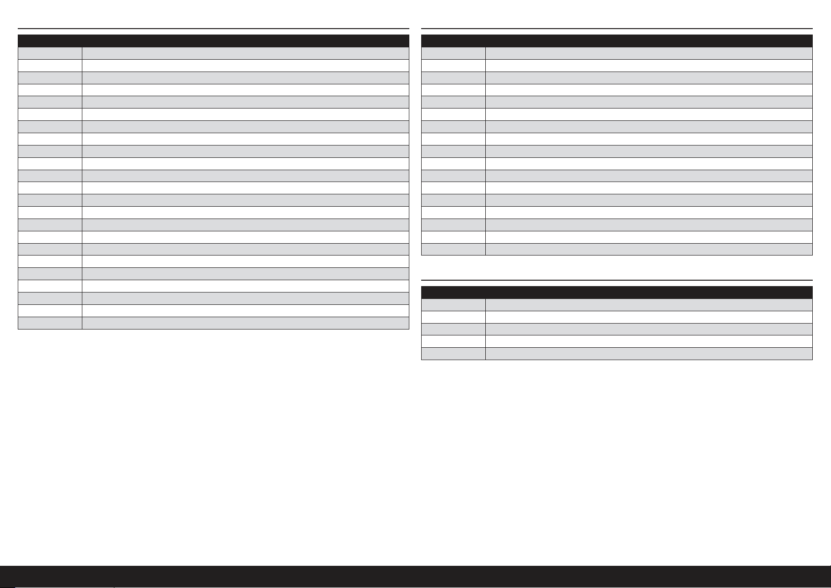
REPLACEMENT PARTS
RECOMMENDED PARTS
Part # Description
EFLG630S Electric Retract
HAN318501 Fuselage
HAN318502 Left-Hand Wing Inner Panel
HAN318503 Right-Hand Wing Inner Panel
HAN318504 Left-Hand Wing Outer Panel
HAN318505 Right-Hand Wing Outer Panel
HAN318506 Left-Hand Winglet
HAN318507 Right-Hand Winglet
HAN318508 Wingtip Wheels
HAN318509 Horizontal Stab
HAN318510 Carbon Wing Joiner
HAN318511 Outer Wing Rods
HAN318512 Winglet Joiners
HAN318513 Servo Covers (6)
HAN318514 Cockpit
HAN318515 Seat
HAN318516 Rudder
HAN318517 Landing Gear Parts
HAN318518 Landing Gear Doors
HAN318519 Tailwheel
HAN318520 Hinges (4)
HAN318521 Airbrake Covers (2)
HAN318522 Wing Retainers (2)
Part # Description
CSE010009700 Talon 90 Heli ESC 010-0097-00
EFLM4060B Power 60 BLOutrunner Mtr, 470Kv
EFLP16080FA Spinner, 45mm: ASW 20 4.7m
HAN495512 Prop 16 x 10: ASW 20 4.7m
KXSB40006S40 F-Tek 4000mAh 6S 40C, EC5, LED
DLMBD38 Liquid Gravity; Weight System
SPMSA7040 A7040 HV Retract Servo
SPMA3005 Heavy-Duty Servo Extension 24-inch
SPMA3004 Heavy-Duty Servo Extension 18-inch
SPMA3006 Heavy-Duty Servo Extension 36-inch
SPMA3007 Heavy-Duty Servo Extension 48-inch
SPMA3054 Servo Connector Clips (25)
SPMAR12310T AR12310T 12CH PowerSafe Tele RX
SPMB4000LPRX 4000mAh 2S 7.4V LiPo Rx Battery
SPMSA5060 A5060 H-T / H-S Mini Metal HV Servo
SPMSA7050 A7050 HV Thin Wing Hi Torq MG
SPMVR5203 VR5203 Dual Output Regulator
OPTIONAL PARTS
Part # Description
SPMA3008 Heavy-Duty Y-Harness 6 inch
SPMAS3000 AS3000 AS3X Stabilization Module
TAM85013 Spray Lacquer TS-13 Clear
TAM86024 PS-24 Fluor Org 100ml Spray Can
TAM87044 Primer White 180ml
22EN
Page 23
HINWEIS
Alle Anweisungen, Garantien und anderen zugehörigen Dokumente können im eigenen Ermessen von Horizon Hobby,
LLC. jederzeit geändert werden Die aktuelle Produktliteratur finden Sie auf horizonhobby.com unter der Registerkarte
„Support“ für das betreffende Produkt.
SPEZIELLE BEDEUTUNGEN
Die folgenden Begriffe werden in der gesamten Produktliteratur verwendet, um auf unterschiedlich hohe
Gefahrenrisiken beim Betrieb dieses Produkts hinzuweisen:
WARNUNG: Wenn diese Verfahren nicht korrekt befolgt werden, ergeben sich wahrscheinlich Sachschäden,
Kollateralschäden und schwere Verletzungen ODER mit hoher Wahrscheinlichkeit oberflächliche Verletzungen.
ACHTUNG: Wenn diese Verfahren nicht korrekt befolgt werden, ergeben sich wahrscheinlich Sachschäden UND die
Gefahr von schweren Verletzungen.
HINWEIS: Wenn diese Verfahren nicht korrekt befolgt werden, können sich möglicherweise Sachschäden UND
geringe oder keine Gefahr von Verletzungen ergeben.
WARNUNG: Lesen Sie die GESAMTE Bedienungsanleitung, um sich vor dem Betrieb mit den Produktfunktionen
vertraut zu machen. Wird das Produkt nicht korrekt betrieben, kann dies zu Schäden am Produkt oder persönlichem
Eigentum führen oder schwere Verletzungen verursachen.
Dies ist ein hochentwickeltes Hobby-Produkt. Es muss mit Vorsicht und gesundem Menschenverstand betrieben
werden und benötigt gewisse mechanische Grundfähigkeiten. Wird dieses Produkt nicht auf eine sichere und
verantwortungsvolle Weise betrieben, kann dies zu Verletzungen oder Schäden am Produkt oder anderen Sachwerten
führen. Dieses Produkt eignet sich nicht für die Verwendung durch Kinder ohne direkte Überwachung eines
Erwachsenen. Verwenden Sie das Produkt nicht mit inkompatiblen Komponenten oder verändern es in jedweder Art
ausserhalb der von Horizon Hobby, LLC vorgegebenen Anweisungen. Diese Bedienungsanleitung enthält Anweisungen
für Sicherheit, Betrieb und Wartung. Es ist unbedingt notwendig, vor Zusammenbau, Einrichtung oder Verwendung
alle Anweisungen und Warnhinweise im Handbuch zu lesen und zu befolgen, damit es bestimmungsgemäß betrieben
werden kann und Schäden oder schwere Verletzungen vermieden werden.
NICHT GEEIGNET FÜR KINDER UNTER 14 JAHREN. DIES IST KEIN SPIELZEUG.
WARNUNGEN UND SICHERHEITS-VORKEHRUNGEN
Bitte lesen und befolgen Sie alle Anweisungen und Sicherheitsvorkehrungen vor dem Gebrauch. Falscher, nicht
sachgemäßer Gebrauch kann Feuer, ernsthafte Verletzungen und Sachbeschädigungen zur Folge haben.
Komponenten
Verwenden Sie mit dem Produkt nur kompatible Komponenten. Sollten Fragen zur Kompatibilität auftreten, lesen Sie
bitte die Produkt- oder Bedienungsanweisung oder kontaktieren den Service von Horizon Hobby.
Fliegen
Fliegen Sie um Sicherheit garantieren zu können, nur in weiten offenen Gegenden. Wir empfehlen hier den Betrieb auf
zugelassenen Modellflugplätzen. Bitte beachten Sie lokale Vorschriften und Gesetze, bevor Sie einen Platz zum Fliegen
wählen.
Propeller
Halten Sie lose Gegenstände die sich im Propeller verfangen können weg vom Propeller. Dieses gilt auch für Kleidung
oder andere Objekte wie zum Beispiel Stifte oder Schraubendreher.
Halten Sie ihre Hände weg vom Propeller, es besteht akute Verletzungsgefahr.
Akkus
Folgen Sie immer den Herstelleranweisungen bei dem Gebrauch oder Entsorgung von Akkus. Falsche Behandlung von
LiPo Akkus kann zu Feuer mit Körperverletzungen und Sachbeschädigung führen.
Kleinteile
Dieser Baukasten beinhaltet Kleinteile und darf nicht unbeobachtet in der Nähe von Kindern gelassen werden, da die
Teile verschluckt werden könnten mit ernsthaften Verletzung zur Folge.
EMPFEHLUNGEN ZUM SICHEREN BETRIEB
• Überprüfen Sie zur Flugtauglichkeit ihr Modell vor jedem Flug.
• Beachten Sie andere Piloten deren Sendefrequenzen ihre Frequenz stören könnte.
• Begegnen Sie anderen Piloten in ihrem Fluggebiet immer höflich und respektvoll.
• Wählen Sie ein Fluggebiet, dass frei von Hindernissen und groß genug ist.
• Stellen Sie vor dem Start sicher, dass die Fläche frei von Freunden und Zuschauern ist.
• Beobachten Sie den Luftraum und andere Flugzeuge/Objekte die ihren Flugweg kreuzen und zu einem Konflikt
führen könnten.
• Planen Sie sorgfältig ihren Flugweg vor dem Start.
VOR DEM ZUSAMMENBAU
• Entnehmen Sie zur Überprüfung jedes Teil der Verpackung.
• Überprüfen Sie den Rumpf, Tragflächen, Seiten- und Höhenruder auf Beschädigung.
• Sollten Sie beschädigte oder fehlende Teile feststellen, kontaktieren Sie bitte den Verkäufer.
• Laden des Senders und Empfängers.
• Zentrieren der Trimmungen und Sticks auf dem Sender.
• Sollten Sie einen Computersender verwenden, resetten Sie einen Speicherplatz und benennen ihn nach dem Modell.
• Sender und Empfänger jetzt nach den Bindeanweisung des Herstellers zu binden.
HINWEIS: Das Funksystem nach dem Einstellen der Ruderausschläge erneut binden. Damit wird verhindert, dass
sich die Servos auf ihre Endpunkte bewegen, ehe Sender und Empfänger verbunden sind. Außerdem wird garantiert,
dass die Servo-Umkehreinstellungen im Funksystem gespeichert werden.
ASH 31 6,4M ARF
23 DE
Page 24
INHALTSVERZEICHNIS
Hinweis .................................................................................................................................................................23
Spezielle Bedeutungen ..........................................................................................................................................23
Vor dem Zusammenbau .........................................................................................................................................23
Spezifikationen ......................................................................................................................................................24
Bauteile (Ohne Kleinteile) .......................................................................................................................................24
Zur Fertigstellung erforderlich ................................................................................................................................25
Optionale Teile .......................................................................................................................................................25
Zusätzliche Teile erforderlich ..................................................................................................................................25
Werkzeuge erforderlich ..........................................................................................................................................25
Vorsichtsmaßnahmen beim Zusammenbau ............................................................................................................26
Transport und Lagerung .........................................................................................................................................26
Pflege der Fluoreszenzfarbe ...................................................................................................................................26
Außentragflächen ..................................................................................................................................................26
Innentragflächen ....................................................................................................................................................28
Montage des Winglets ............................................................................................................................................31
Montage des Seitenruders .....................................................................................................................................31
Montage des Höhenruders .....................................................................................................................................33
SPEZIFIKATIONEN BAUTEILE (OHNE KLEINTEILE)
252 in (6.4m)
1920 sq in (123.87 dm2)
88 in (2.2m)
Montage der Schleppkupplung ..............................................................................................................................34
Montage des Funkgeräts .......................................................................................................................................34
Montage des Cockpits ...........................................................................................................................................35
Montage des optionalen Elektroantriebssystems ....................................................................................................35
Abschließende Montage .........................................................................................................................................38
Ausbalancieren des Flugzeugs ...............................................................................................................................39
Ruderausschlag .....................................................................................................................................................40
Vorflugkontrolle .....................................................................................................................................................40
Täglicher Flug Check ............................................................................................................................................40
Garantie Und Service Informationen ....................................................................................................................... 40
Garantie und Service Kontaktinformationen............................................................................................................41
Rechtliche Informationen für die Europäische Union ...............................................................................................41
Anweisungen zur Entsorgung von Elektro- und Elektronik-Altgeräten für Benutzer in der Europäischen Union ........41
Ersatzeile ...............................................................................................................................................................42
Zur Fertigstellung erforderlich ................................................................................................................................42
Optionale Teile .......................................................................................................................................................42
26 lbs (11.8 kg)
6Kanäle (oder mehr) mit 7Servos
24DE
Page 25
ZUR FERTIGSTELLUNG ERFORDERLICH ZUSÄTZLICHE TEILE ERFORDERLICH
Alle Versionen
Erforderliche
Anz.
1 SPMAR12310T AR12310T PowerSafe Tele RX mit 12 Kanälen
4 SPMSA5060 A5060 H-T/H-S HV-Mini-Metall-Servo
2 SPMSA7050 A7050 HV dünne Tragfläche MG hoher Drehzahl
3 SPMA3003 Servokabelverlängerung 300 mm
8 SPMA3004 Servokabelverlängerung 460 mm
5 SPMA3005 Servokabelverlängerung 600 mm
4 SPMA3007 Servokabelverlängerung 1200 mm
1 SPMA3008 Heavy Duty Y-Kabelbaum, 150 mm
2 SPMB4000LPRX LiPo-Empfängerakku (7,4 V / 4000 mAh)
1 SPMA3054 Servosteckerklemmen (25)
1 SPMVR5203 VR5203 dualer Leistungsregler
Antriebslose Version für Schleppstart
Erforderliche
Anz.
1 SPMSA7040 A7040 HV Einfahr-Servo
Elektrisch angetriebene Version
Erforderliche
Anz.
1 CSE010009700 Talon 90 A 25 V bürstenloser Geschwindigkeitsregler mit 20 A BEC
1 EFLM4060B Bürstenloser Außenläufer-Motor Leistung 60, 470Kv
1 EFLP16080FA Spinner, 45mm: ASW 20 4,7m
1 HAN495512 Propeller 16 x 10: ASW 20 4,7m
1 KXSB40006S40 F-Tek 4000mA 6S 40C, EC5, LED
OPTIONALE TEILE
Teile-Nr. Beschreibung
SPMA3008 Heavy Duty Y-Kabelbaum, 150 mm
SPMAS3000 AS3000 AS3X Stabilisierungsmodul
TAM85013 Sprühlack TS-13 Klar
TAM86024 PS-24 Neon-Orange 100ml Sprühdose
TAM87044 Grundierung Weiß 180ml
Teile-Nr. Beschreibung
Teile-Nr. Beschreibung
DLMBD38 Liquid Gravity-Ballastkugeln; Gewichtssystem
Teile-Nr. Beschreibung
Sender mit 6Kanälen
LiPo-Ladegerät
WERKZEUGE ERFORDERLICH
Balancierständer
Ringschlüssel: 17mm
Klemmen
klares Klebeband
Crimpzange
Cyanacrylat-(CA-)Klebstoff, dünn und mittel
Bohrer mit verschieden großen Aufsätzen
Epoxid
Pinsel
Faserstift
Isopropyl Alkohol
Klemme
Hex drivers, metric, various sizes
Hobbymesser mit # 11 Klinge
Langes Kunststoff-Gestänge
Klebeband mit geringer Klebekraft
Schleifpapier mittel
Metrisches Lineal
Mikroballons
Mischbecher und Rührstäbchen
Papiertücher
Stift
Phillips Schraubendreher: #1,#2
Handbohrer
Zange
Rotationswerkzeug mit Schneidscheibe, Schleifband, Hartmetallschneide, Schleifstein
Lötkolben und Lot
Schnur
Beschreibung
Beschreibung
ASH 31 6,4M ARF
25 DE
Page 26
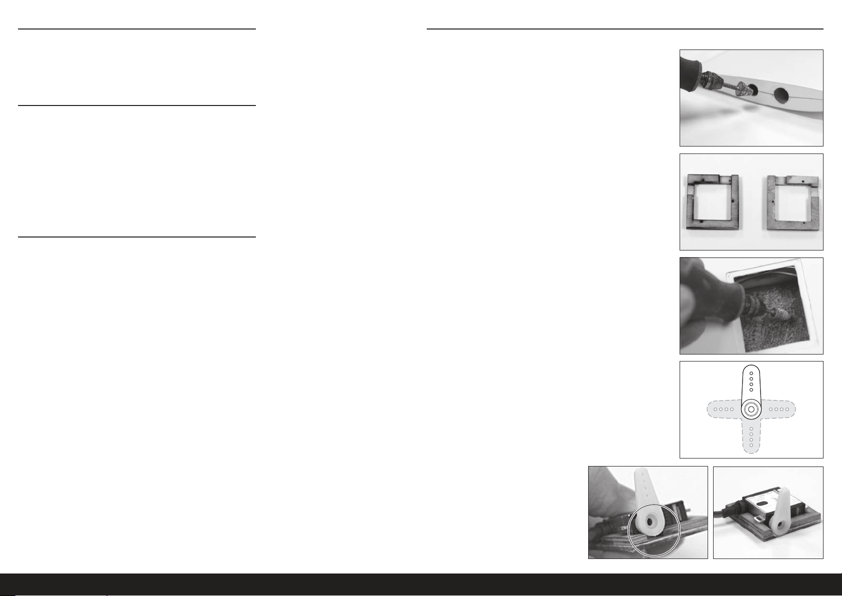
VORSICHTSMASSNAHMEN BEIM ZUSAMMENBAU
Die Arbeitsfläche vor dem Zusammenbau vorbereiten. Die Oberfläche
sollte weich und frei von scharfen Objekten sein. Wir empfehlen, die
Teile des Flugwerks auf einem weichen Handtuch oder einer Matte zu
lagern, um Kratzer oder Beulen an der Oberfläche des Flugzeugs zu
vermeiden.
TRANSPORT UND LAGERUNG
Beim Transport und der Lagerung des Modells müssen mindestens
2m (80Zoll) in der Länge und 46cm (18Zoll) in der Höhe vorhanden
sein, um die Größe des Rumpfs aufnehmen zu können. Wir empfehlen
außerdem die Verwendung von Tragflächen- und Stabilisatortaschen,
um diese Oberflächen bei Transport und Lagerung zu schützen. Die
Steuerhörner und Gestänge können Schäden an anderen Oberflächen
verursachen, auch wenn sie in Taschen gelagert sind. Die Tragflächen
und den Stabilisator immer transportieren und lagen, damit die
Gestänge andere Platten nicht berühren und somit Schäden verhindert
werden.
PFLEGE DER FLUORESZENZFARBE
Die auf dem Modell verwendete Fluoreszenzfarbe kann bei direkter
Sonneneinstrahlung im Laufe der Zeit verblassen. Um die Beständigkeit
der Fluoreszenzfarbe auf dem Flugzeug zu erhöhen, die direkte
Sonneneinstrahlung einschränken, wenn das Flugzeug nicht geflogen
wird.
Sollten Reparaturen notwendig sein oder falls die Farbe der optionalen
Teile der Rumpffarbe entsprechen soll, dann ist Tamiya-Sprühfarbe,
PS-24 Neon-Orange eine gute Entsprechung der auf dem Modell
verwendeten Farbe. Die besten Ergebnisse werden erzielt, wenn PS-24
über Tamiya Grundierung Weiß, fein (TAM87044) gesprüht und mit
Tamiya TS-13 Klarlack lackiert wird.
AUSSENTRAGFLÄCHEN
1. Das Klebeband entfernen und die Oberfläche der Tragflächen
reinigen und polieren.
2. Eine Zugangsöffnung mit einem Rotationswerkzeug in das
Wurzelende an der Außentragfläche schneiden.
TIPP: Die Öffnung gerade groß genug gestalten, damit der ServoAnschluss hindurch passt. Ist die Öffnung zu groß, so kann die
nicht verbundene Verlängerung zurück in die Tragfläche fallen.
3. Die kurzen Servohalterungen ausfindig machen. Vorbohrungen für
die Schrauben der Servohalterung bohren.
4. Die Montageoberfläche des Tragflächenservos für die
Servohalterung mit einem Rotationswerkzeug auf niedriger
Geschwindigkeit oder 80-körniges Sandpapier aufrauen. Die
Innenfläche der Tragflächen nur leicht aufrauen, damit das Epoxid
greifen kann. NICHT durch die Oberfläche der Tragfläche schleifen.
Die Montageflächen mit Brennspiritus oder 91%igen IPA gründlich
reinigen.
5. 3 Arme eines 4-armigen Servohorns abschneiden.
6. Den Servo mit montiertem Servoarm probeweise einsetzen. Die
Öffnung in der Halterung bei Bedarf vergrößern, damit der Servo
vollständig in der Halterung sitzt.
Ebenfalls die Schrauben der Servohalterung probeweise
einsetzen, um sicherzustellen, dass sie nicht aus der Halterung
hervorstehen und die Oberfläche der Tragfläche beschädigen.
Stehen die Schrauben hervor, diese abschneiden, damit sie unter
der Oberfläche der Halterung liegen.
26DE
Page 27

7. Die Tragfläche an der Servoabdeckung messen und markieren –
10mm von der erhöhten Außenkante der Abdeckung und 45mm
von der erhöhten Hinterkante.
Bei der Montage des Rahmens in die Tragfläche richtet sich die
Kante des Rahmens mit den vorderen und hinteren Markierung aus
und der Servoausgang mit der Markierung von 45mm.
45mm
10mm
12. Den Servoarm montieren. Den Servo in der Halterung mit den
kurzen Servo-Schrauben (2x8mm) montieren.
8. Die Servohalterung mit Epoxid (DLMAD64) an der Tragfläche
montieren. Sicherstellen, dass der Servoarm mit dem OberflächenSteuerhorn ausgerichtet ist. Die Kerbe des Armdurchgangs sollte
auf die Flügelspitze weisen und die Kerbe der Servoleitung nach
vorn. Die Montagefläche der Servohalterung mit einem Papiertuch
und Alkohol vom Epoxid befreien, der das Einsetzen des Servos in
die Halterung beeinträchtigen könnte. Das Epoxid muss vollständig
ausgehärtet sein.
9. Antirotationsstifte mit Epoxid in das Wurzelende montieren.
Die Stifte nicht weiter als die Hälfte der Stifte eindrücken.
Überschüssiges Epoxid mit einem Papiertuch und Alkohol
abwischen.
10. Eine 305mm (12Zoll) Servoleitung mit dem Servo des Querruders
verbinden. Die Verlängerung mit einer Servo-Anschlussklemme
(SPMA3054) oder einem Schrumpfschlauch sichern.
11. Entweder eine Schnur mit einem angebrachten Gewicht oder ein
langes Kunststoff-Gestänge verwenden, um die zusammengesetzte
Servoverlängerung durch die Tragfläche und aus der zuvor
geschnittenen Zugangsöffnung zu fädeln.
TIPP: Die Schnur oder das Kunststoff-Gestänge durch die
Zugangsöffnung durch die Servoabdeckung führen und die
Servoleitung an dem Ende anbringen. Das Ende der Servoleitung
durch die Zugangsöffnung ziehen.
13. Die Öffnung in der Abdeckung für den Servoarm genau messen
und mit einem Rotationswerkzeug oder Hobbymesser schneiden.
Die Abdeckung oft probeweise einsetzen, um den ausreichenden
Durchgang des Servoarms durch den vollständigen Verfahrweg des
Servos sicherzustellen. Die Außenecken der Abdeckung runden,
damit diese komplett in der eingelassenen Montagefläche in der
Tragfläche sitzt.
14. Ein Stück des weißen UltraTrim-Klebebands (HANU80000)
schneiden, das etwa 3cm größer als die Servoabdeckung ist.
15. Das Klebeband abziehen und auf die lackierte Seite der
Servoabdeckung kleben.
TIPP: In der Mitte der Abdeckung beginnen und vorsichtig nach
außen zu den Rändern sämtliche Luftblasen und Falten aus dem
Klebeband drücken.
Die Öffnung für den Servoarm schneiden und entfernen. Das
Klebeband etwa 10mm hinter der Kante der Abdeckung kürzen
und die Ecken entsprechend der Abbildung abschrägen, um zu
verhindern, dass sich die Ecken nach der Nutzung lösen.
16. Die Servoabdeckung vorsichtig auf der Tragfläche montieren,
indem die Abdeckung in die Aussparung der Tragfläche gesetzt und
das Klebeband um den Umfang der Abdeckung auf die Tragfläche
gedrückt wird. Von der Abdeckung nach außen arbeiten, um
sämtliche Luftblasen oder Falten zu entfernen.
ASH 31 6,4M ARF
27 DE
Page 28
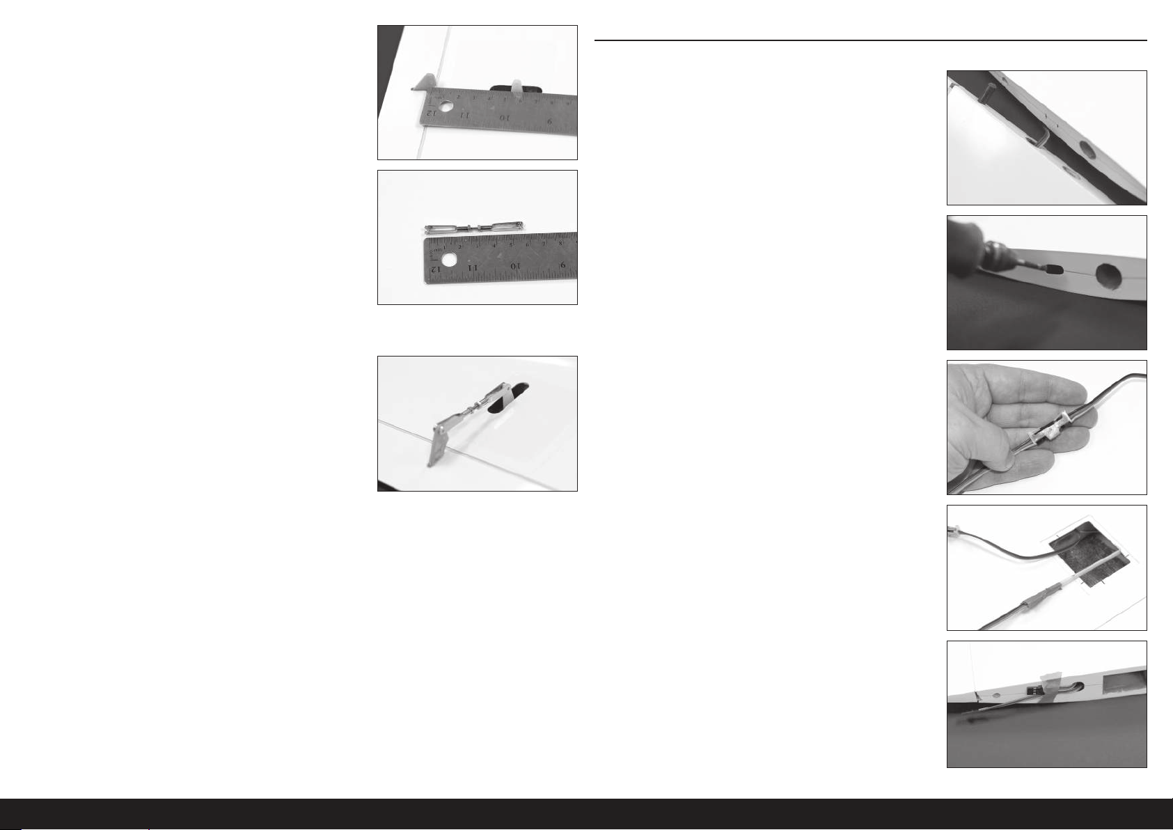
17. Das Querruder wird in der Mitte gehalten und zwischen den
Löchern des Servoarms und des Steuerhorns messen.
18. Die Länge des Querruders laut dem im vorherigen Schritt
gewonnenen Messwerts einrichten, indem auf der Gabelkopf auf
einem der Enden des Gestänges nach außen oder innen gedreht
wird. Nach Erreichen der korrekten Länge, Gewindesicherung
auftragen und die Mutter gegen den Gabelkopf festziehen.
Versuchen, den Gewindestab zwischen den zwei Gabelköpfen zu
zentrieren.
TIPP: Der überstehende Gewindestab kann nach Bedarf
abgeschnitten werden. Der Stab sollte innerhalb des Gabelkopfs
entsprechend der Abbildung noch mindestens 3Windungen
aufweisen.
INNENTRAGFLÄCHEN
1. Das Klebeband entfernen und die Oberfläche der Tragflächen
reinigen und polieren.
2. Die fertige Außentragfläche entsprechend der Abbildung neben
die Innentragfläche legen. Die Position der Zugangsöffnung der
Außentragfläche auf der Innentragfläche markieren.
3. Zugangsöffnungen in die äußeren und Wurzelenden der
Innentragfläche schneiden. Die Öffnungen sollten groß genug sein,
damit die Servo-Anschlüsse hindurch passen, ohne dass die Enden
zurück in die Tragfläche fallen.
19. Das Gestänge auf dem Servo und den Ruderhörnern montieren.
Sicherstellen, dass die Steuerfläche bei Neutralstellung des Servos
zentriert ist.
20. Die Schritte 1-19 für die entgegengesetzte Außentragfläche
wiederholen.
4. Eine Servoverlängerung von 122cm (48Zoll) und von 61cm
(24Zoll) zusammenschließen, um eine innere QuerruderVerlängerung zu erzeugen. Mit einer Klemme oder einem
Schrumpfschlauch sichern.
5. Ein langes Kunststoff-Gestänge oder eine gewichtete Schnur durch
die geschnittene Zugangsöffnung in eines der Ende der Tragfläche
hinein und aus der Servoabdeckung der Klappe herausführen. Ein
Ende der zusammengesetzten Servoverlängerung des Querruders
am Gestänge anbringen. Das Ende der Verlängerung durch die
Tragfläche und aus der Zugangsöffnung ziehen. Das Ende der
Verlängerung mit Klebeband am Ende der Tragfläche ankleben.
Den Vorgang am anderen Ende der Tragfläche wiederholen,
um das gegenüberliegende Ende der Servoverlängerung des
Querruders durch die Zugangsöffnung im anderen Ende der
Tragfläche zu ziehen.
28DE
Page 29

10mm
6. Eine Servoverlängerung von 46cm (18Zoll) an der Störklappen-
Leitung anschließen und mit einer Klemme oder einem
Schrumpfschlauch sichern. Die Verlängerung durch das innere
Ende der Tragfläche wie zuvor führen.
11. Die Servohalterung der Klappe mit Epoxid montieren. Die Halterung
mit der im vorangehenden Schritt vorgenommenen Markierung
ausrichten. Sämtliches Epoxid entfernen, das in die Schlitze der
Halterungsösen oder die innere Grundplatte der Halterung gelaufen
ist und den Servo beeinträchtigen könnte. Sicherstellen, dass sich
die Halterung mit dem Tragflächenholm sowie der Oberfläche
bindet, und dass der Servoarm mit dem Steuerhorn der Klappe
ausrichten wird. Das Epoxid muss vollständig aushärten.
7. Mit Heißkleber oder Kontaktkleber, wie Deluxe Systems
Foam2Foam (DLMAD34), die Leitungen von Querruder und
Störklappe am Holm an der Vorderseite der Servoabdeckung
sichern. Damit wird ein Verrutschen oder Stören der Leitungen mit
dem Servoarm der Klappe und dem Gestänge vermieden.
8. Vorsichtig das Gewebe von den Servo-Halterungsösen trimmen.
Den Servo probeweise in die Servohalterung einsetzen. Der Servo
sollte sehr passgenau in der Halterung sitzen.
9. Die Montageoberfläche der Flügelklappe für die Servohalterung
mit einem Rotationswerkzeug auf niedriger Geschwindigkeit oder
80-körniges Sandpapier aufrauen. Die Innenfläche der Tragflächen
nur leicht aufrauen, damit das Epoxid greifen kann. NICHT durch
die Oberfläche der Tragfläche schleifen. Die Montageflächen mit
Brennspiritus oder IPA gründlich reinigen.
12. Den Servoarm der Klappe auf eine Länge von zuschneiden.
13. Den Servo zentrieren und das Steuerhorn in einem leichten Winkel
zur Hinterkante der Tragfläche montieren.
14. Den Servo entsprechend der Abbildung in die Halterung schieben.
15. Mit der bereitgestellten Acetat-Vorlage eine Servo-Rückhalteplatte
aus 3mm (1/8Zoll) und 1,5mm (1/16Zoll) Sperrholz erzeugen.
10. Die Öffnung der Servohalterung der Klappe messen und markieren,
entsprechend der Abbildung 12mm vom hinteren Rand der
Aussparung und 17mm vom äußeren Rand der Aussparung.
ASH 31 6,4M ARF
17mm
12mm
29 DE
Page 30

79mm
16. Den Servo mit der Servo-Rückhalteplatte und zwei Schrauben in
der Halterung sichern. Sicherstellen, dass die Schraubenköpfe
nicht über die Montagefläche der Servohalterung ragen, und dass
die Schrauben die Außenfläche der Tragfläche nicht beschädigen.
17. Eine Servoverlängerung von 61cm (24Zoll) an der Servoleitung
anschließen und mit einer Klemme oder einem Schrumpfschlauch
sichern. Die Verlängerung durch das Tragflächenwurzelende der
Tragfläche wie zuvor mit einem langen Kunststoff-Gestänge oder
einer gewichteten Schnur führen.
20. Die Servoabdeckung mit Klebeband wie bei der Außentragfläche
an der Tragfläche montieren.
18. Die Gestänge auf eine Länge von 79mm zuschneiden.
19. Das Gestänge auf dem Klappenhorn und dem Servoarm montieren.
Die Klappen nach unten auslenken und ein Ende des Gestänge
durch das Loch in der Hinterkante der Tragfläche führen und
am Servoarm anschließen. Das andere Ende des Gestänges am
Steuerhorn der Klappe anschließen.
21. Antirotationsstifte mit Epoxid in das Wurzelende am Ende der
Platte montieren. Überschüssiges Epoxid mit einem Papiertuch
und Alkohol abwischen.
22. Die Abdeckung der Gestängeöffnung der Klappe zuschneiden und
an der Oberseite der Tragfläche mit Kontaktkleber anbringen.
23. Die Schritte 1-22 für die entgegengesetzte Innentragfläche
wiederholen.
30DE
Page 31
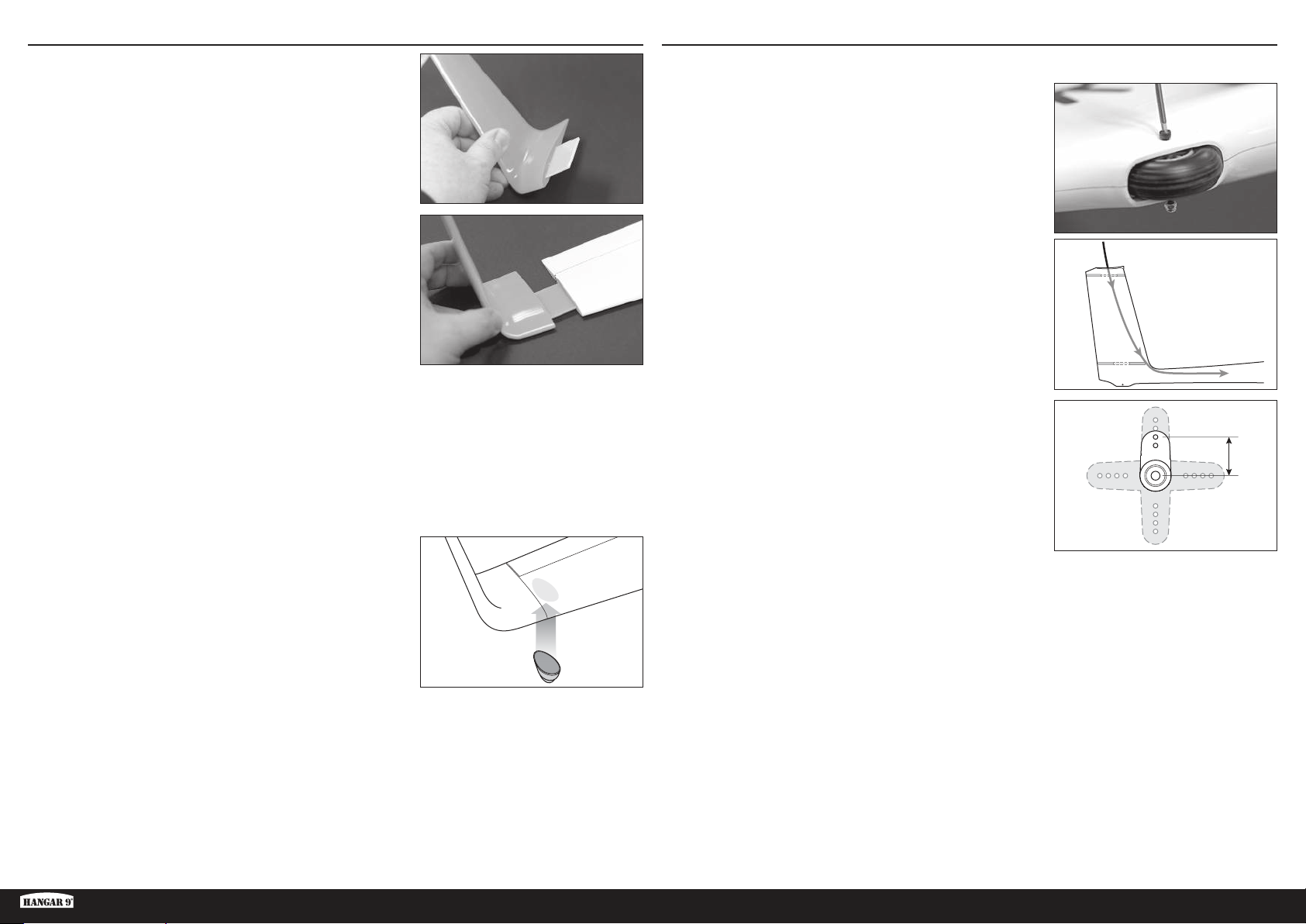
13mm
MONTAGE DES WINGLETS
1. Das Winglet-Blatt in den Winglet-Schlitz schieben.
2. Die Baugruppe in den Schlitz in der Spitze der Außentragfläche
schieben.
MONTAGE DES SEITENRUDERS
1. Den Rumpf reinigen und polieren.
2. Das Spornrad mit einem 2,5mm Sechskantschlüssel entfernen.
3. Eine gewichtete Schnur oder ein langes, flexibles Gestänge durch
die Servo-Öffnung des Höhenruders, durch das Seitenleitwerk,
durch das schmale Loch auf der Vorderseite der Servo-Öffnung des
Seitenruders und hoch zum Rumpfende schieben. Damit werden
später die Servoverlängerungen von Seitenruder und Höhenruder
durch den Rumpf gezogen.
3. Das Winglet-Blatt bei Bedarf auf Länge kürzen, um einen engen
Sitz des Winglet gegen die Tragfläche zu erzielen. Zwischen der
Tragfläche und dem Winglet sollte es keine Lücke geben.
4. Das Blatt sollte eng im Winglet und in der Außentragfläche sitzen.
Das Winglet sollte mit Klebeband zur zusätzlichen Sicherung in
Position geklebt werden.
5. Das Rad der Flügelspitze mit Epoxid an der Unterseite der
Außentragfläche nahe der Spitze anbringen.
TIPP: Mit Sandpapier feiner Körnung oder einem
Scheuerschwamm die Oberfläche der Tragfläche, dort wo das Rad
angebracht wird, sehr leicht aufrauen, damit das Epoxid greifen
kann.
Die Schritte 1-5 für die entgegengesetzte Flügelspitze
wiederholen.
4. Einen Servoarm auf 13mm kürzen.
5. Den Servo des Seitenruders zentrieren und den Servoarm
montieren.
6. Ein Servoverlängerung von 152cm (60Zoll) wird für den Servo
des Seitenruders benötigt. Eine Verlängerung von 1219mm
(48Zoll) und von 305mm (12Zoll) mit dem Servo des Seitenruders
verbinden. Alle Verbindungen mit Servo-Anschlussklemmen oder
einem Schrumpfschlauch sichern.
ASH 31 6,4M ARF
31 DE
Page 32
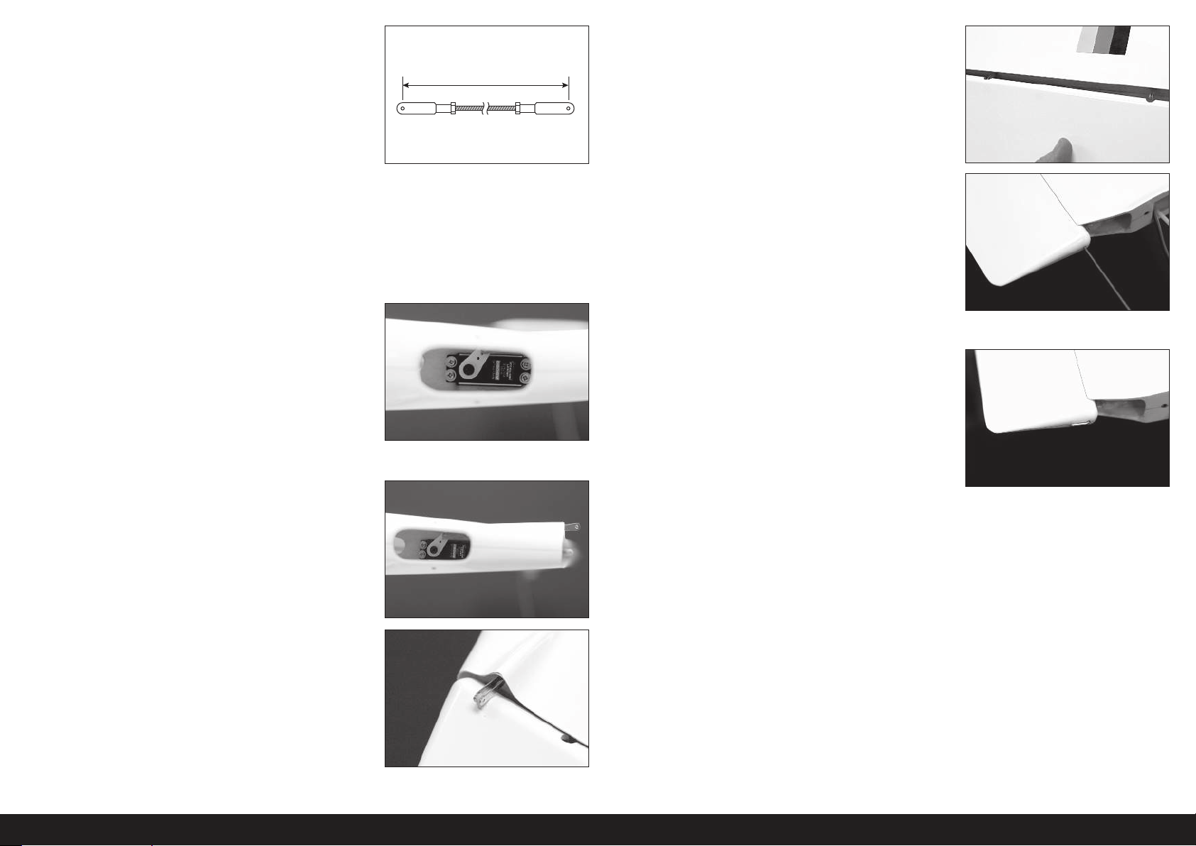
95mm
7. Das Seitenruder-Gestänge kürzen, sodass die Fertiglänge zwischen
den Gabelkopfstiften 95mm beträgt. Ein Ende des Gestänge am
Servoarm des Seitenruders anbringen.
12. Das Seitenruder über die Scharnierpunkte im Seitenleitwerk
schieben.
8. Während der Rumpf umgekehrt auf einem Ständer liegt, die
Servoverlängerung durch die Aussparung des Seitenruder-Servos
und aus der Aussparung des Höhenruder-Servos an der Oberseite
des Seitenleitwerks führen. Diese Verlängerung wird später mit der
Servoverlängerung des Höhenruders durch den Rumpf gezogen.
9. Den Servo des Seitenruders durch die Spornrad-Öffnung und in die
Servohalterung montieren. Der Servo wird so montiert, dass die
Antriebswelle zur Vorderseite des Flugzeugs zeigt und der Servoarm
zur rechten Seite des Rumpfs. Beim Einsetzen des Servo das offene
Ende des Gestänges durch die geformte Öffnung im Heck führen.
Etwas Spannung auf der Servoleitung belassen, um sicherzustellen,
dass die Leitung in der Öffnung nicht gequetscht wird.
TIPP: Mit einem Magnetschraubendreher oder einem normalen
Schraubendreher mit angebrachten Magneten die Servoschrauben
montieren.
10. Das Servohorn drehen, sodass das Gestänge aus der Rückseite des
Seitenleitwerks hervorsteht.
13. Den Scharnierstift des Seitenruders vorsichtig durch das Loch
auf der Oberseite des Seitenruders einführen und vollständig
durch jeden Scharnierpunkt führen, bis er auf der Unterseite des
Seitenruders austritt.
TIPP: Der Scharnierstift ist eine feste Friktionspassung. Es kann
beim Einführen des Stifts notwendig sein, leicht am Seitenruders zu
drücken oder zu schieben, damit der Stift vollständig platziert wird.
Keine Kraft zum Durchführen des Stifts aufwenden. Bei Widerstand
das Seitenruder leicht bewegen und mit dem Einführen des Stifts
fortfahren.
14. Ist der Scharnierstift vollständig eingesetzt, so kann er mit
Klebeband auf der Oberseite bei Bedarf oder wenn er übermäßig
locker ist, festgeklebt werden.
11. Das Steuerhorn des Seitenruder am Gestänge montieren.
32DE
Page 33

53mm
10mm
MONTAGE DES HÖHENRUDERS
1. Ein Servoverlängerung von 152cm (72Zoll) wird für den Servo des
Höhenruders benötigt. Eine Verlängerung von 1219mm (48Zoll)
und von 305mm (24Zoll) miteinander verbinden und am Servo
des Höhenruders anbringen. Alle Verbindungen mit Klemmen oder
einem Schrumpfschlauch sichern.
2. Die Enden der Servoverlängerung von Seiten- und Höhenruder
am Ende des flexiblen Gestänges oder der bereits im
Rumpf eingeführten Schnur mit Klebeband festkleben. Die
Servoverlängerungen vorsichtig durch den Rumpf und aus dem
Cockpit ziehen.
3. Den Servo des Höhenruders einsetzen, wobei die Antriebswelle
zur Vorderseite des Flugzeugs weist. Sicherstellen, dass die
Servoleitung nicht gequetscht wird.
4. Das Höhenruder-Gestänge kürzen, sodass die Fertiglänge zwischen
den Gabelkopfstiften 53mm beträgt. Die Gabelköpfe sollten im
Winkel von 90° zueinander stehen.
6. Das eine Ende des Gestänges am Servoarm des Höhenruders und
das andere Ende am Steuerhorn des Höhenruders anbringen.
7. Das Höhenruder-Gestänge mit dem angebrachten Servoarm
durch die Oberseite des Seitenleitwerks führen. Den Servo
des Höhenruders zentrieren. Das Servohorn entsprechend der
Abbildung in einem Winkel von 90° an der Servo-Antriebswelle
anbringen.
8. Die Höhenflosse mit zwei M4x20mm Flachkopfschrauben am
Seitenleitwerk anbringen.
5. Den Servoarm des Höhenruders auf 10mm kürzen.
ASH 31 6,4M ARF
33 DE
Page 34
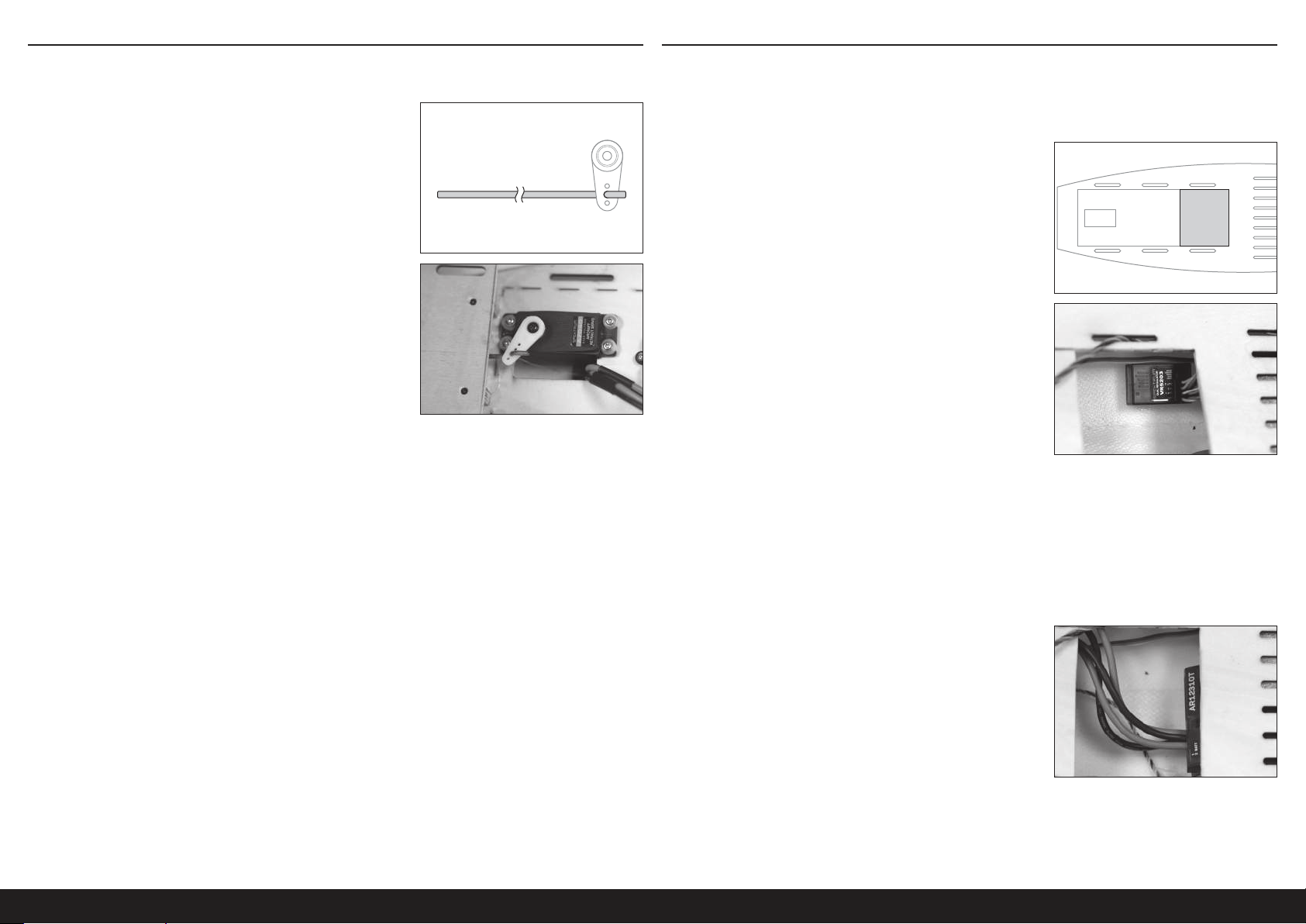
MONTAGE DER SCHLEPPKUPPLUNG MONTAGE DES FUNKGERÄTS
WICHTIG: Bei der Montage des optionalen Elektroantriebs diesen Abschnitt überspringen und
zum Abschnitt „Montage des optionalen Elektroantriebssystems“ gehen.
1. Das Kabel der Schleppkupplung am Servoarm montieren.
2. Den Servo der Schleppkupplung in der Rumpfnase montieren.
Das Auslösekabel durch das kleine Loch auf der Vorderseite des
Cockpits schieben. Den Arm am Servo anbringen und sicherstellen,
dass sich das Kabel an einem Ende des Servo-Verfahrwegs öffnet
und an der gegenüberliegenden Seite des Verfahrwegs vollständig
schließt.
3. WICHTIG: Während die Störklappen und die Einfahrvorrichtung bei 7,2V arbeiten, empfehlen wir für eine
erhöhte Lebensdauer und Zuverlässigkeit eine Regulierung des Stromeingangs für diese Bauteile auf 5,2V unter
Verwendung eines in der Leitung integrierten Spannungsregler, wie SPMVR5203.
Falls die Einfahrvorrichtung auf der regulierten Spannung langsamer funktioniert oder sich nicht vollständig in die
verriegelte Position einfahren lässt, dann die Einfahrvorrichtung bei 7,2V direkt zum Empfänger leiten.
1. Die Rückseite des Cockpitbodens im dargestellten Bereich
vorsichtig schneiden.
2. Die Kanäle für Fahrwerk und Störklappen vom Empfänger an die
Eingangsanschlüsse des Reglers anschließen.
3. Die Ausgangsanschlüsse des Reglers an die Fahrwerkleitung und
den Y-Kabelbaum der Störklappen anschließen.
4. Alle Servoleitungen vom Heck zur Vorderseite des Rumpfs verlegen
und so weit wie möglich gruppiert halten. Mit Kabelbinder oder
Klettband die Leitungen im Rumpf sichern.
5. Sechs Servoleitungen von 46cm (18Zoll) Länge vorbereiten,
jeweils zwei für Querruder, Landeklappen und Störklappen.
TIPP: Klebeband verschiedener Farben zum Umwickeln der
Leitungsenden verwenden, um zu unterscheiden, welche Leitung
zu welcher Steuerfläche gehört.
6. Alle Servoleitungen mit den entsprechenden
Empfängeranschlüssen verbinden.
7. Den Empfänger entsprechend der Abbildung unter dem hinteren
Teil des Cockpitbodens befestigen. Bei Bedarf kleine Stücke
Schaumstoff oder Klettband zum Halten des Empfängers in seiner
Position verwenden.
TIPP: Falls gewünscht, Löcher in den hinteren Cockpitboden
schneiden und die Servoleitungen zum Empfänger führen.
8. Die Empfänger-Akku vorübergehend so weit vorn wie möglich im Cockpit anbringen. Die Akku-Position wird nach
der Bestimmung des korrekten Schwerpunkts endgültig festgelegt. Bei der antriebslosen Segelflieger-Version
werden die Akkus so weit vorn wie möglich zusammen mit zusätzlichem Buggewicht angebracht.
Die elektrisch angetriebene Version benötigt kein zusätzliches Buggewicht zum Ausbalancieren und erfordert
abhängig vom verwendeten Motor-Akku ein Verschieben der Elektrisch angetriebene Versions nach hinten.
34DE
Page 35
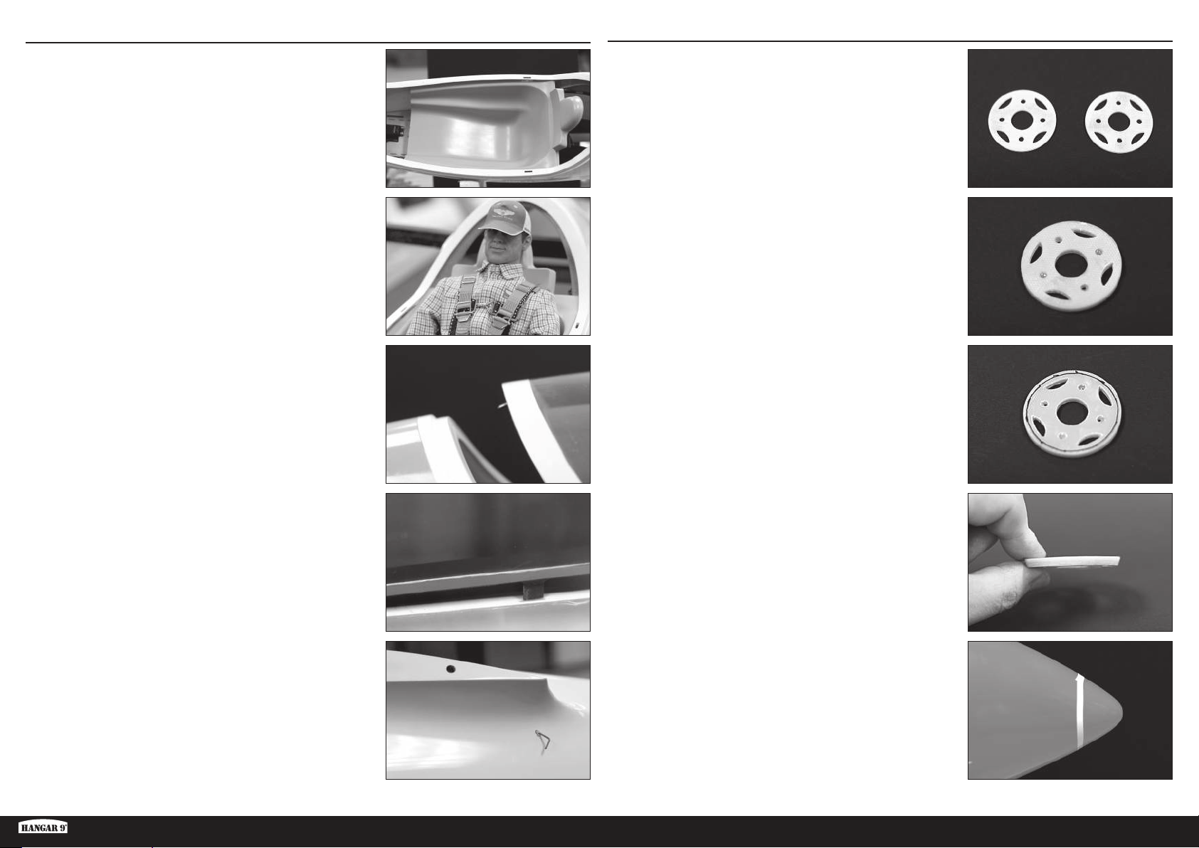
MONTAGE DES COCKPITS
1. Die Cockpitwanne aus Glasfaser montieren. Die Seiten der Wanne
sanft zusammendrücken, damit diese zwischen und unter die
geformten Rumpfseiten passt. Die Löcher in der Wanne sollten
sich mit den Löchern im Rumpf ausrichten. Es ist nicht notwendig,
die Wanne im Rumpf zu sichern. Die Wanne kann entfernt
werden, um den Zugriff auf den hinteren Rumpf und den unteren
Cockpitbereich zu ermöglichen.
MONTAGE DES OPTIONALEN ELEKTROANTRIEBSSYSTEMS
1. Eine Seite jedes Motorhalterungsstück mit 80-körnigen Sandpapier
aufrauen.
2. Bei Bedarf einen optionalen Piloten in der Wanne für eine
zusätzliche Maßstabsgetreue montieren. Es ist nicht notwendig,
den Piloten in der Wanne zu sichern.
TIPP: Hangar 9 ist mit zwei Unternehmen eine Partnerschaft
eingegangen, die kundenspezifische Piloten anbieten. www.
warbirdpilots.com in den USA und www.tailoredpilots.com im
Vereinigten Königreich bieten detaillierte und für ASH 31 geeignete
Pilotenfiguren an.
3. Die Kanzel am Rumpf montieren, indem der Stift auf der
Vorderseite der Kanzel in das Loch auf der Vorderseite des Rumpfs
eingeführt wird und die Rückseite des Kanzel nach unten gegen
den Rumpf gedreht wird, um sicherzustellen, dass die Ösen zur
seitlichen Ausrichtung in die Löcher im Rumpf einrasten.
2. Mit 5-minütigem Epoxid die aufgerauten Seiten der beiden
Motorhalterungsstücke zusammenkleben und sicherstellen,
dass die Löcher korrekt ausgerichtet sind. Überschüssiges
Epoxid mit Alkohol und einem Papiertuch abwischen. Die Stücke
zusammenklemmen, bis das Epoxid vollständig ausgehärtet ist.
3. Entsprechend der Abbildung eine Linie um eine Seite der Halterung
etwa 1,5mm von der Außenkante ziehen.
4. Mit der Linie als Orientierungshilfe eine Schräge auf der Kante der
Halterung schleifen, indem entlang der Kante von der Ecke zur
Linie geschliffen wird.
4. Den Kanzelverschluss unter der linken Tragflächenwurzel
hineinschieben, bis die Kanzel gesichert ist. Es kann notwendig
sein, leicht auf die Rückseite der Kanzel zu drücken, damit diese
vollständig einrastet. Der Seilverschluss weist absichtlich einen
engen Sitz auf, damit ein Lösen der Kanzel während des Flugs
verhindert wird.
ASH 31 6,4M ARF
5. Mit Klebeband von 3mm (1/8Zoll) eine Linie 25mm von der
Rumpfnase nach hinten markieren.
35 DE
Page 36
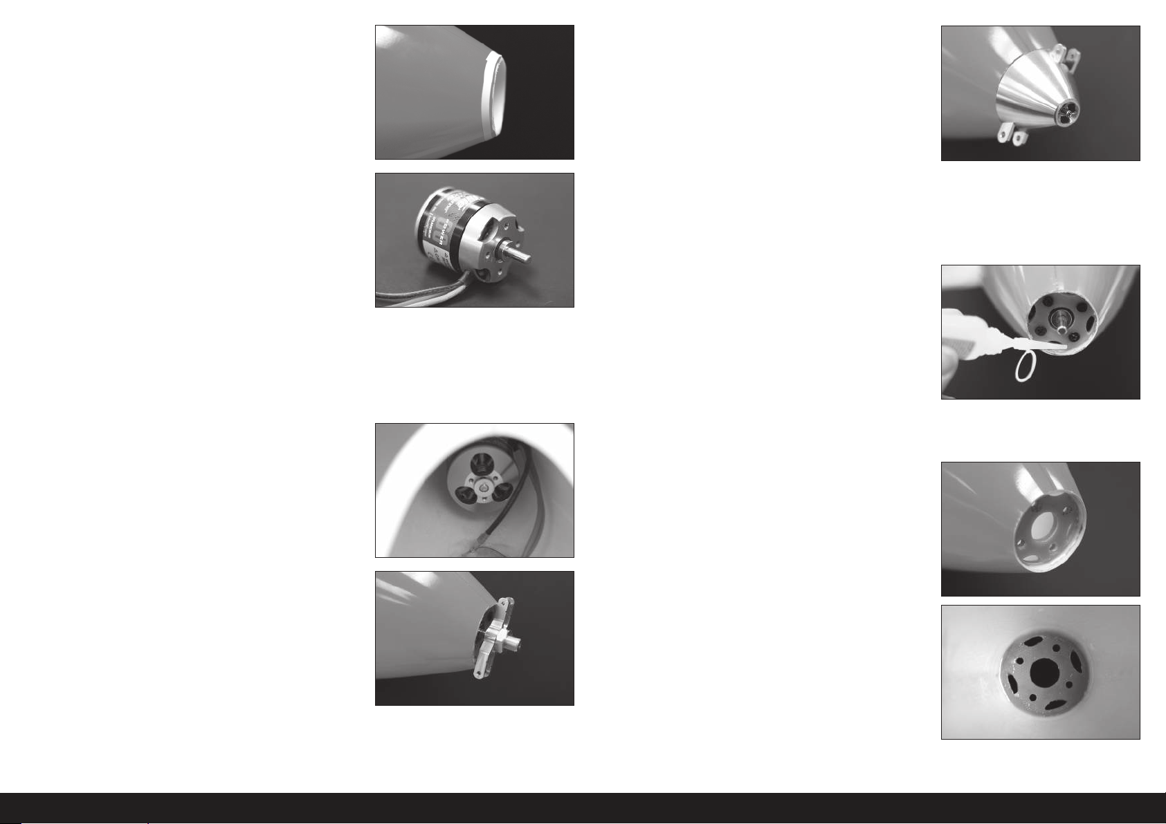
6. Die Nase vorsichtig mit einem Rotationswerkzeug und
angebrachter Schneidscheibe vorsichtig vom Rumpf schneiden.
Nicht bis ganz zum Klebeband schneiden. Etwas Überschuss
belassen, der später abgeschleift wird.
11. Den Motor nach vorne drücken und die Zentralschraube des
Spinners festziehen, während gegen den Motor gedrückt wird. Die
Schraube gerade so festziehen, dass sie den Motor hält, jedoch die
Platzierung des Spinners gegen den Rumpf noch ermöglicht.
12. Mit dem Spinner den Motor mit der Rumpfnase ausrichten.
7. Entsprechend den dem Motor beiliegenden Anweisungen die
Orientierung der Motorwelle für die Montage des Motors auf der
Rückseite der Halterung ändern.
8. Die Motorhalterung mit den mit dem Motor mitgelieferten
Schrauben am Motor anbringen. Bei Bedarf einen Senker zum
Anschrägen der Löcher in der Befestigungsplatte verwenden.
Sicherstellen, dass die Schmalseite der zuvor in die Halterung
geschliffene Schräge vom Motor weg weist.
9. Den Motor und die Halterung in der Rumpfnase von innen
einführen.
10. Den Propelleradapter auf die Motorwelle drücken und die
Propellermutter lose montieren. Den Spinner über dem
Propelleradapter montieren. Sicherstellen, dass der Spinner über
dem Adapter sitzt. Die Zentralschraube des Spinners montieren.
13. Ist die Ausrichtung korrekt, den Motor im Rumpf stillhalten und die
Spinner-Baugruppe durch Lösen der Zentralschraube des Spinners
vorsichtig entfernen und dabei vorsichtig vorgehen, um den Motor
nicht zu verschieben. Die Spinner-Baugruppe von der Motorwelle
schieben.
14. Die Motorhalterung bei entferntem Spinner vorübergehend mit eine
paar Tropfen mittleren CA-Klebstoff und Beschleuniger um den
Befestigungsring am Rumpf festkleben.
15. Die Schrauben der Motorhalterung entfernen und dann den Motor,
dabei vorsichtig vorgehen, um die Motorhalterung nicht vom Rumpf
abzubrechen.
16. DIESEN SCHRITT NICHT ÜBERSPRINGEN. Einen Tropfen Epoxid
großzügig um die Verbindung zwischen der Halterung, sowohl vor
als auch hinter der Motorhalterung, und dem Rumpf auftragen.
Das Epoxid in die Verbindung drücken und glattstreichen, damit es
eine Leiste formt. Das Epoxid muss vor dem Fortsetzen vollständig
ausgehärtet sein.
36DE
Page 37
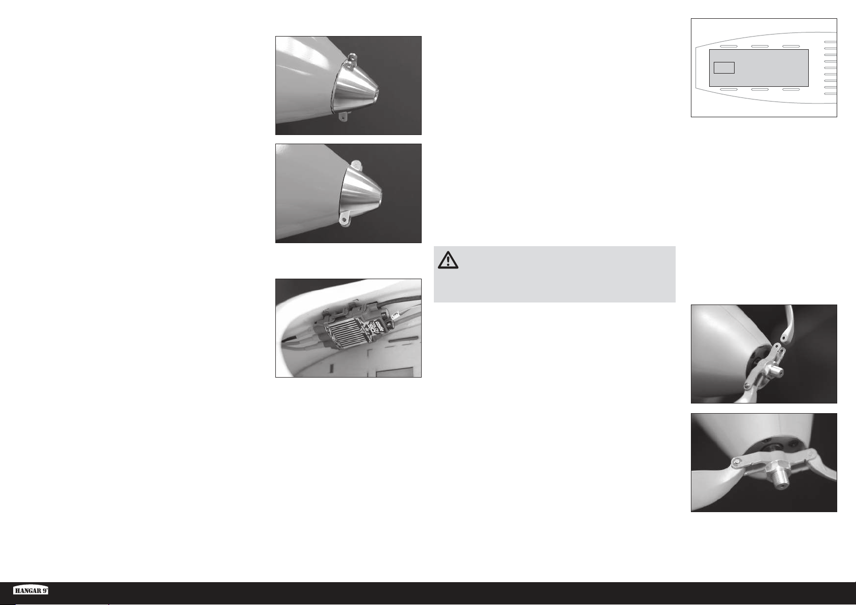
17. Den Motor und die Spinner-Baugruppe vorübergehend montieren.
18. Messen und 1mm vom Spinner entfernt eine Markierung auf dem
Rumpf ziehen.
19. Die Spinner-Baugruppe und den Motor entfernen und die
Vorderseite des Rumpfs bis zur Linie schleifen.
TIPP: Einen Schleifblock verwenden, damit die Vorderseite des
Rumpfs gerade bleibt. Das Material langsam entfernen und den
Fortschritt häufig prüfen. Ziel ist es, eine perfekt gerade Linie zu
erhalten, die parallel zur Rückseite des Spinners um den Umfang
des Rumpfs liegt.
24. Den abgebildeten Bereich des Cockpitbodens ausschneiden und
entfernen.
25. Den Motor-Akku im Cockpitboden anbringen und mit Klettbändern
durch die vorgeschnittenen Öffnungen im Cockpitboden sichern.
26. Die Empfänger-Akkus auf der Rückseite des Cockpits anbringen.
Die Empfänger-Akkus können entsprechend verschoben werden,
um die Balance des Flugzeugs anzupassen. Bei der Verwendung
der empfohlenen optionalen Antriebssystembauteilen sollte kein
zusätzlicher Ballast erforderlich sein. Jedoch mit dem Abschnitt
„Ausbalancieren des Flugzeugs“ fortfahren, um den korrekten
Schwerpunkt zu bestätigen.
20. Den Motor mit mittlerer Gewindesicherung in der Motorhalterung
montieren.
21. Mit Klettband oder Servo-Klebeband den Geschwindigkeitsregler
im Cockpit montieren.
22. Die Motorleitungen entsprechend den mit dem Motor und
dem Geschwindigkeitsregler mitgelieferten Anweisungen am
Geschwindigkeitsregler anschließen.
23. Die Gasleitung des Geschwindigkeitsreglers an den
entsprechenden Empfänger-Anschluss anschließen.
ACHTUNG: Niemals ohne ein korrektes Ausbalancieren des
Flugzeugs fliegen. Ein nicht ausbalanciertes Flugzeug ist
extrem instabil, was zu einem Absturz führen kann. Schäden durch
Abstürze sind durch die Gewährleistung nicht gedeckt.
27. Den Spinnerbügel durch Montage der kegelförmigen Welle und
der Mutter vorbereiten. Die Mutter zum jetzigen Zeitpunkt nicht
festziehen.
28. Den Sitz der Propellerblätter zum Bügel überprüfen. Das Blatt sollte
sich bei montiertem Stift ungehindert bewegen. Ist dies nicht der
Fall, die Blätter dort leicht schleifen, wo sie den Bügel berühren,
um eine ungehinderte Bewegung zu ermöglichen.
29. Wenn die Blätter in den Bügel passen, die Blätter mit den Stiften
und Klemmen im Bügel sichern. Sicherstellen, dass die Vorderseite
der Blätter zur gekerbten Seite des Bügels weisen.
30. Die Baugruppe an der Motorwelle einpassen. Überprüfen, dass
sich der Bügel ungehindert drehen kann und die Vorderseite des
Rumpfs während seines vollen Umlaufs nicht berührt. Mit einem
12mm Steckschlüssel die Mutter festziehen, um so Bügel und
Adapter zu sichern.
31. Den Spinner montieren und sicherstellen, dass er in die Aussparungen im Propellerbügel passt. Den Spinner mit der mit dem Spinner
mitgelieferten Schraube und einem Kreuzschlitzschraubendreher Nr.1 am Adapter sichern.
TIPP: Der Spinner und die Propellerblätter können lackiert werden, damit sie dem Neon-Orange der Flugzeugnase entsprechen, wobei die
im Abschnitt „Pflege der Fluoreszenzfarbe“ genannten Produkte verwendet werden sollten, die den Spinner und Propeller während des
Flugs fast unsichtbar werden lassen.
ASH 31 6,4M ARF
37 DE
Page 38
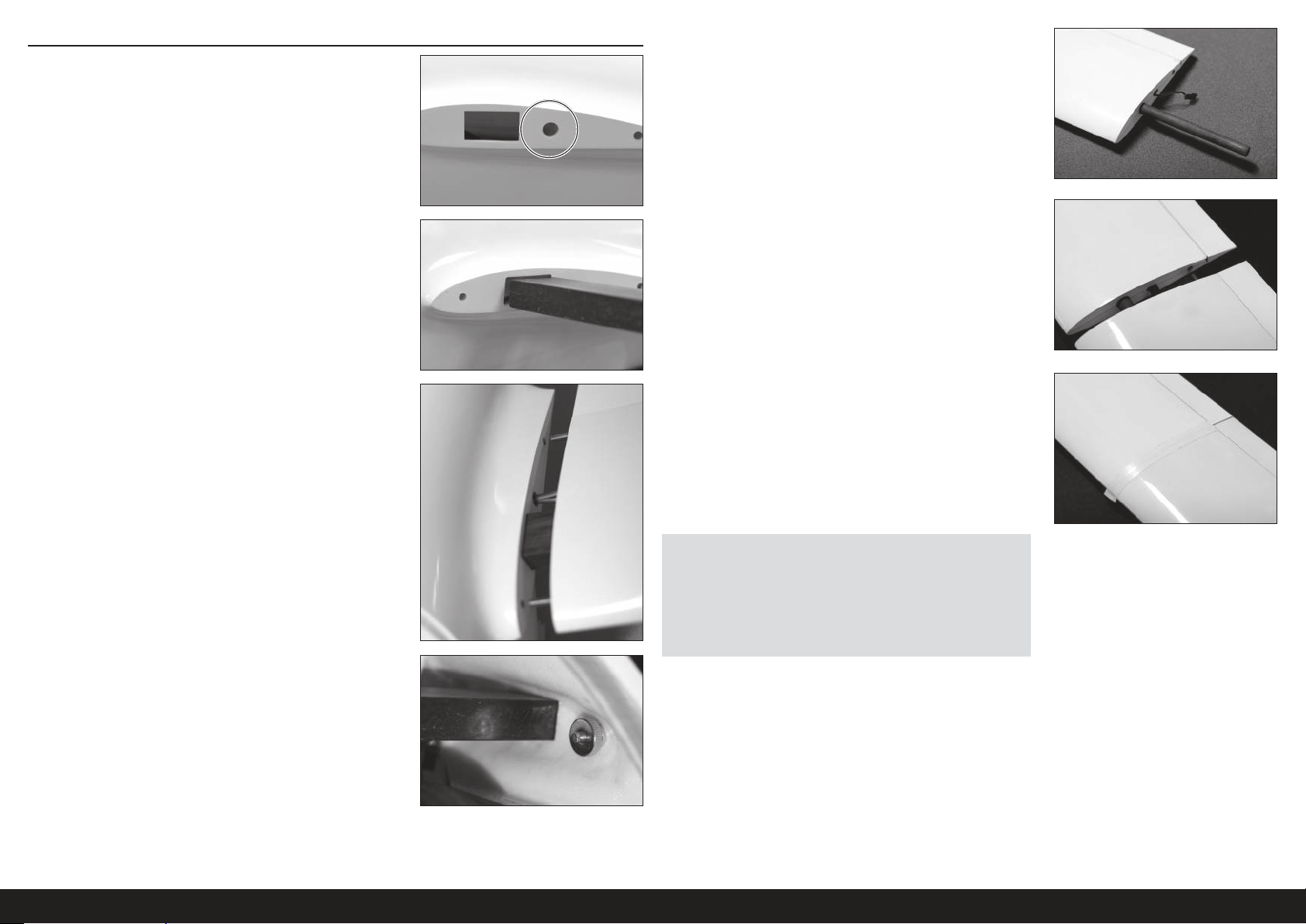
ABSCHLIESSENDE MONTAGE
1. Ein Loch in die Tragflächenwurzel des Rumpf für die verschiedenen
Servoleitungen der Tragfläche schneiden. Sicherstellen, dass sich
das Loch mit dem bereits geschnittenen Loch in der Wurzel der
Innentragfläche ausrichtet und groß genug ist, damit die Stecker
der Servoleitung hindurch passen. Scharfe Kanten um das Loch
mit Sandpapier entfernen.
2. Die Tragflächensteckung in den Rumpf einführen. Die Steckung
sollte passgenau in der Rumpföffnung sitzen. Sicherstellen, dass
die Steckung im Rumpf zentriert ist.
5. Ein äußeren Steckungsrohr auf das Außenende der Innentragfläche
schieben.
6. Die Außentragflächen über das Steckungsrohr schieben, bis die
Außentragfläche die Innentragfläche berührt. Sicherstellen das
der Führungsstift der Tragfläche in der Ausrichtungsbohrung der
Tragfläche eingesteckt ist.
3. Die Innentragflächen über die Enden der Tragflächensteckung
schieben und dabei die Servoleitungen anschließen und den
Führungsstift der Tragfläche im Rumpf einstecken.
4. Die Haltemutter der Tragfläche auf die Stiftschraube der Tragfläche
von der Innenseite des Rumpfs schrauben. Die Haltemutter
handfest festziehen und sicherstellen, dass die verschiedenen
Servoleitungen zwischen der Tragfläche und dem Rumpf nicht
gequetscht werden.
7. Die Naht zwischen Innen- und Außentragfläche mit Klebeband
umwickeln. Sicherstellen, dass das Klebeband den Betrieb der
Steuerflächen der Tragflächen nicht beeinträchtigt. Weißes PVCIsolierband wird empfohlen. Wir haben festgestellt, dass dieses
Band mehr als ausreichend ist, die Außentragflächen während des
Flugs, selbst bei aggressiven Flugmanövern, festzuhalten.
HINWEIS: Immer sicherstellen, dass die Tragfläche vor der
Montage des Klebeband sauber, trocken und frei von Staub oder
Verschmutzungen ist.
HINWEIS: Nach dem Zerlegen der Tragfläche das Klebeband nicht
erneut verwenden. Beim erneuten Zusammenbau der Tragfläche jedes
Mal neues Klebeband verwenden.
8. Das Winglet entsprechend der Beschreibung im Abschnitt Montage
des Winglets montieren.
9. Die Schritte 1-8 für die entgegengesetzte Tragfläche wiederholen.
10. Cockpitschale, Pilot und Kanzel am Rumpf montieren.
38DE
Page 39
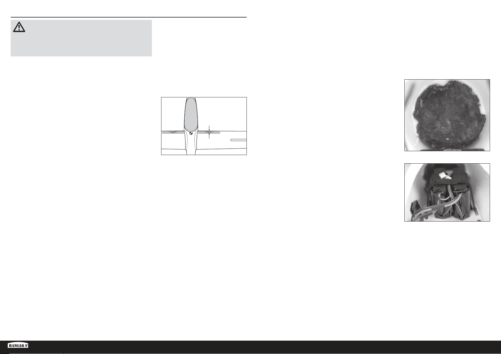
AUSBALANCIEREN DES FLUGZEUGS
ACHTUNG: DIESEN SCHRITT NICHT ÜBERSPRINGEN. Niemals
ohne ein korrektes Ausbalancieren des Flugzeugs fliegen. Ein
nicht ausbalanciertes Flugzeug ist extrem instabil, was zu einem
Absturz führen kann. Schäden durch Abstürze sind durch die
Gewährleistung nicht gedeckt.
Ballast der Flugzeugnase hinzufügen, bis das Flugzeug auf dem
Ständer waagerecht oder mit der Nase leicht nach unten liegt.
TIPP: Eine Plastiktüte an der Außenseite der Rumpfnase mit
Klebeband festkleben und Gewicht, wie Bleischrot oder Deluxe
Materials Liquid Gravity (DLMBD38), der Tüte hinzufügen, bis das
Flugzeug ausbalanciert ist.
1. Die Tragflächen, die Kanzel und Leitwerkflächen am Rumpf
anbringen. Sicherstellen, dass die Leitungen von Querruder,
Landeklappen und Störklappen an den entsprechenden
Leitungen vom Empfänger angeschlossen sind. Sicherstellen,
dass die Leitungen nicht außerhalb des Rumpfs liegen, ehe
die Flügelschrauben festgezogen werden. Das Modell sollte in
einem ansonsten flugbereiten Zustand vor dem Ausbalancieren
ausgeschaltet sein.
2. Der empfohlene Schwerpunkt (CG) für das Modell liegt 60–85mm
hinter der Vorderkante der Tragfläche an der Wurzel. Die CGPosition auf den Tragflächen mit Klebeband oder einem Markierer
markieren. Bringen Sie Ihr Modellflugzeug manuell oder mit
einem Lastgestell, das das Modell an den Markierungen auf der
Unterseite des Flügels abstützt, in die senkrechte Stellung.
3. Das Flugzeug mit den Fingern oder einem käuflich erhältlichen
Ständer aufrecht an den auf der Tragfläche angebrachten
Markierungen abstützen.
Bei der antriebslosen Version für Schleppstart mit Schritt5
fortfahren.
23/8–35/16 inches
(60–85 mm)
5. Tragflächen, Kanzel und Flug-Akkus aus dem Rumpf entfernen und
den Rumpf vorsichtig auf seine Nase stellen.
6. Den Ballast von Schritt5 mit Epoxid und Mikroballons mischen
und in die Innenseite der Rumpfnase geben. Die Mischung
vollständig aushärten lassen.
TIPP: Eine Alternative zum direkten Hinzufügen des Ballast in
den Rumpf ist die Verwendung des Spinners der Hangar 9 RV-4
(HAN488509) als Form zum Aufbewahren der Epoxid/BallastMischung, bis diese ausgehärtet ist. Dieser Spinner weist eine
fast perfekte Übereinstimmung zur Form der ASH-Nase auf. Die
Ballastmischung in den Spinner gießen. Die Mischung kann nach
dem vollständigen Aushärten aus dem Spinner entfernt werden
und mit Epoxid sicher in der Rumpfnase montiert werden.
Die Flug-Akkus wieder in ihre Position im Cockpit bringen und
dort sichern.
4. Bei der elektrisch angetriebenen Version die Empfänger-Akkus im
Cockpit nach vorn oder hinten verschieben, bis das Flugzeug auf
dem Ständer waagerecht oder mit der Nase leicht nach unten liegt.
Wurde der korrekte Schwerpunkt erreicht, die Empfänger-Akkus mit
Klettband am Rumpf montieren.
Mit dem Abschnitt Ruderausschlag fortfahren.
TIPP: Kann ein korrekter Gleichgewichtspunkt bei vollständig
vorne angebrachten Empfänger-Akkus nicht erreicht werden,
selbstklebendes Gewicht hinzufügen, bis das Flugzeug
ausbalanciert ist.
ASH 31 6,4M ARF
39 DE
Page 40
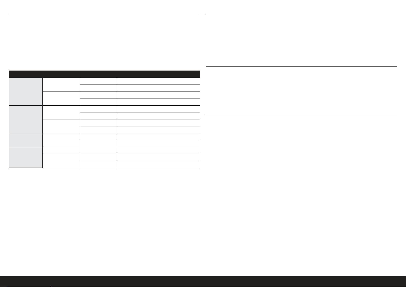
RUDERAUSSCHLAG
1. Den Sender und Empfänger des Modells einschalten. Die Bewegung des Seitenruders mit dem Empfänger prüfen.
Wird der Hebel nach rechts bewegt, sollte sich auch das Seitenruder nach rechts bewegen. Die Richtung auf dem
Servo am Empfänger bei Bedarf umkehren.
2. Die Bewegung des Höhenruders mit dem Funksystem prüfen. Wird der Hebel des Höhenruders auf dem Sender
nach unten bewegt, so bewegt sich das Höhenruder des Flugzeugs nach oben.
3. Die Bewegung des Querruders mit dem Funksystem prüfen. Wird der Hebel des Querruders nach rechts bewegt, so
bewegt sich das rechte Querruder nach oben und das linke Querruder nach unten.
4. Mit einem Lineal den Ausschlag von Höhen-, Quer- und Seitenruder einstellen.
Oberfläche Rate Richtung Ausschlag
Lande-/Steig-Modus
Querruder
Flieg-/Start-Modus
Hoch
Höhenruder
Niedrig
Seitenruder Hoch
Landen Nach unten 25–30mm
Flaperon
• Im Lande- bzw. Steigmodus bewegen sich die Querruder unabhängig von den Flaperons.
• Im Lande- oder Steigmodus, die gesamte Hinterkante (Flaperons und Querruder) um 3-4mm senken.
• Im Flieg- oder Start-Modus die Querruder und die Flaperons für eine vollständige Quersteuerung miteinander
koppeln.
• Im Lande- oder Steigmodus, die gesamte Hinterkante (Flaperons und Querruder) um 3-4mm nach oben drehen.
• Einen Schieberegler verwenden, um den Flaperon-Ausschlag so zu steuern, dass der Bewegungsspielraum variiert
werden kann.
• Wir empfehlen, die Flaperons im Rise-Off-Ground- (ROG-) Startmodus und im Schleppflug um 10 mm zu senken.
• Den Ruder-Ausschlag auf einen Wert einstellen, der den Servomechanismus nicht bindet.
• Den maximalen Flaperon-Ausschlag auf einen Wert einstellen, der den Servomechanimus nicht bindet.
Dies sind allgemeine Richtlinien, die von unseren eigenen Testflügen stammen. Sie können mit verschiedenen Werten
experimentieren, die zu Ihrem bevorzugten Flugstil passen.
Wegverstellung und Ersatztrimmungen sind nicht aufgeführt und sollten entsprechend dem Einzelmodell und Vorlieben
eingestellt werden. Die Steuerhörner immer im Winkel von 90° zur Mittellinie des Servos montieren. Ersatztrimmungen
als letzten Ausweg zur Zentrierung der Servos verwenden.
Das Funksystem erneut binden, nachdem alle Ruderausschläge eingestellt wurden, um zu verhindern, dass sich die
Servos zu ihren Endpunkten bewegen, ehe Sender und Empfänger angeschlossen sind.
Flieg-/Start-Modus
Nach oben 16mm
Nach unten 12mm
Nach oben 18–20mm
Nach unten 14mm
Nach oben 9mm
Nach unten 7mm
Nach oben 7mm
Nach unten 5mm
Rechts 35–45mm
Links 35–45mm
Nach oben 18–20mm
Nach unten 14mm
VORFLUGKONTROLLE
• Akkus für Sender, Empfänger und Motor aufladen. Die dem Ladegerät beigelegten Anweisungen befolgen. Die
Anweisungen des Herstellers der elektrischen Bauteile befolgen.
• Prüfen Sie den RC Einbau und stellen sicher dass alle Ruderfunktionen (Quer-, Höhen-, Seitenruder) und Gas sich in
die richtige Richtung mit den empfohlenen Ausschlägen bewegen.
• Überprüfen Sie alle Teile der Anlenkungen (Ruderhörner, Servohebel und Gabelköpfe) und stellen sicher dass diese
gut befestigt und in einwandfreiem Zustand sind.
• Lassen Sie den Motor laufen. Wiederholen Sie mit laufenden Motor den Reichweitencheck. Die Reichweite sollte
nicht signifikant beeinflußt werden.
TÄGLICHER FLUG CHECK
• Überprüfen Sie die Spannung des Senderakkus. Fliegen Sie nicht wenn die Spannung unterhalb der vom Hersteller
empfohlenen Spannung liegt, da dieses zu einem Absturz führen könnte.
• Überprüfen Sie alle montierten Teile (Verbindungen, Schrauben, Muttern und Bolzen vor jedem Flug. Stellen Sie
sicher, dass nichts blockiert und alle Teile vernünftig gesichert sind.
• Stellen Sie sicher, dass sich alle Ruder in die richtige Richtung bewegen.
• Führen Sie einen Reichweitentest vor jeder Flugsession durch.
• Alle Servoleitungen und Stecker der Schalterkabel sollten im Empfänger gesichert sein.
GARANTIE UND SERVICE INFORMATIONEN
Warnung
Ein ferngesteuertes Modell ist kein Spielzeug. Es kann, wenn es falsch eingesetzt wird, zu erheblichen Verletzungen
bei Lebewesen und Beschädigungen an Sachgütern führen. Betreiben Sie Ihr RC-Modell nur auf freien Plätzen und
beachten Sie alle Hinweise der Bedienungsanleitung des Modells wie auch der Fernsteuerung.
Garantiezeitraum
Exklusive Garantie Horizon Hobby LLC (Horizon) garantiert, dass dasgekaufte Produkt frei von Material- und
Montagefehlern ist. Der Garantiezeitraum entspricht den gesetzlichen Bestimmung des Landes, in dem das Produkt
erworben wurde. In Deutschland beträgt der Garantiezeitraum 6 Monate und der Gewährleistungszeitraum 18 Monate
nach dem Garantiezeitraum.
Einschränkungen der Garantie
(a) Die Garantie wird nur dem Erstkäufer (Käufer) gewährt und kann nicht übertragen werden. Der Anspruch
des Käufers besteht in der Reparatur oder dem Tausch im Rahmen dieser Garantie. Die Garantie erstreckt sich
ausschließlich auf Produkte, die bei einem autorisierten Horizon Händler erworben wurden. Verkäufe an dritte werden
von dieser Garantie nicht gedeckt. Garantieansprüche werden nur angenommen, wenn ein gültiger Kaufnachweis
erbracht wird. Horizon behält sich das Recht vor, diese Garantiebestimmungen ohne Ankündigung zu ändern oder
modifizieren und widerruft dann bestehende Garantiebestimmungen.
(b) Horizon übernimmt keine Garantie für die Verkaufbarkeit des Produktes, die Fähigkeiten und die Fitness des
Verbrauchers für einen bestimmten Einsatzzweck des Produktes. Der Käufer allein ist dafür verantwortlich, zu prüfen,
ob das Produkt seinen Fähigkeiten und dem vorgesehenen Einsatzzweck entspricht.
(c) Ansprüche des Käufers ¬ Es liegt ausschließlich im Ermessen von Horizon, ob das Produkt, bei dem ein Garantiefall
festgestellt wurde, repariert oder ausgetauscht wird. Dies sind die exklusiven Ansprüche des Käufers, wenn ein Defekt
festgestellt wird.
Horizon behält sich vor, alle eingesetzten Komponenten zu prüfen, die in den Garantiefall einbezogen werden können.
Die Entscheidung zur Reparatur oder zum Austausch liegt nur bei Horizon. Die Garantie schließt kosmetische Defekte
oder Defekte, hervorgerufen durch höhere Gewalt, falsche Behandlung des Produktes, falscher Einsatz des Produktes,
kommerziellen Einsatz oder Modifikationen irgendwelcher Art aus. Die Garantie schließt Schäden, die durch falschen
Einbau, falsche Handhabung, Unfälle, Betrieb, Service oder Reparaturversuche, die nicht von Horizon ausgeführt
wurden aus.
40DE
Page 41
Ausgeschlossen sind auch Fälle die bedingt durch (vii) eine Nutzung sind, die gegen geltendes Recht, Gesetze oder
Regularien verstoßen haben. Rücksendungen durch den Käufer direkt an Horizon oder eine seiner Landesvertretung
bedürfen der Schriftform.
Schadensbeschränkung
Horizon ist nicht für direkte oder indirekte Folgeschäden, Einkommensausfälle oder kommerzielle Verluste, die in
irgendeinem Zusammenhang mit dem Produkt stehen verantwortlich, unabhängig ab ein Anspruch im Zusammenhang
mit einem Vertrag, der Garantie oder der Gewährleistung erhoben werden. Horizon wird darüber hinaus keine
Ansprüche aus einem Garantiefall akzeptieren, die über den individuellen Wert des Produktes hinaus gehen. Horizon hat
keinen Einfluss auf den Einbau, die Verwendung oder die Wartung des Produktes oder etwaiger Produktkombinationen,
die vom Käufer gewählt werden. Horizon übernimmt keine Garantie und akzeptiert keine Ansprüche für in der folge
auftretende Verletzungen oder Beschädigungen. Mit der Verwendung und dem Einbau des Produktes akzeptiert der
Käufer alle aufgeführten Garantiebestimmungen ohne Einschränkungen und Vorbehalte.
Wenn Sie als Käufer nicht bereit sind, diese Bestimmungen im Zusammenhang mit der Benutzung des Produktes zu
akzeptieren, werden Sie gebeten, dass Produkt in unbenutztem Zustand in der Originalverpackung vollständig bei dem
Verkäufer zurückzugeben.
Sicherheitshinweise
Dieses ist ein hochwertiges Hobby Produkt und kein Spielzeug. Es muss mit Vorsicht und Umsicht eingesetzt werden
und erfordert einige mechanische wie auch mentale Fähigkeiten. Ein Versagen, das Produkt sicher und umsichtig
zu betreiben kann zu Verletzungen von Lebewesen und Sachbeschädigungen erheblichen Ausmaßes führen. Dieses
Produkt ist nicht für den Gebrauch durch Kinder ohne die Aufsicht eines Erziehungsberechtigten vorgesehen. Die
Anleitung enthält Sicherheitshinweise und Vorschriften sowie Hinweise für die Wartung und den Betrieb des Produktes.
Es ist unabdingbar, diese Hinweise vor der ersten Inbetriebnahme zu lesen und zu verstehen. Nur so kann der falsche
Umgang verhindert und Unfälle mit Verletzungen und Beschädigungen vermieden werden.
Fragen, Hilfe und Reparaturen
Ihr lokaler Fachhändler und die Verkaufstelle können eine Garantiebeurteilung ohne Rücksprache mit Horizon nicht
durchführen. Dies gilt auch für Garantiereparaturen. Deshalb kontaktieren Sie in einem solchen Fall den Händler, der
sich mit Horizon kurz schließen wird, um eine sachgerechte Entscheidung zu fällen, die Ihnen schnellst möglich hilft.
Wartung und Reparatur
Muss Ihr Produkt gewartet oder repariert werden, wenden Sie sich entweder an Ihren Fachhändler oder direkt an
Horizon.
Rücksendungen / Reparaturen werden nur mit einer von Horizon vergebenen RMA Nummer bearbeitet. Diese Nummer
erhalten Sie oder ihr Fachhändler vom technischen Service. Mehr Informationen dazu erhalten Sie im Serviceportal
unter www. Horizonhobby.de oder telefonisch bei dem technischen Service von Horizon.
Packen Sie das Produkt sorgfältig ein. Beachten Sie, dass der Originalkarton in der Regel nicht ausreicht, um
beim Versand nicht beschädigt zu werden. Verwenden Sie einen Paketdienstleister mit einer Tracking Funktion und
Versicherung, da Horizon bis zur Annahme keine Verantwortung für den Versand des Produktes übernimmt.
Bitte legen Sie dem Produkt einen Kaufbeleg bei, sowie eine ausführliche Fehlerbeschreibung und eine Liste aller
eingesendeten Einzelkomponenten. Weiterhin benötigen wir die vollständige Adresse, eine Telefonnummer für
Rückfragen, sowie eine Email Adresse.
Garantie und Reparaturen
Garantieanfragen werden nur bearbeitet, wenn ein Originalkaufbeleg von einem autorisierten Fachhändler beiliegt, aus
dem der Käufer und das Kaufdatum hervorgeht. Sollte sich ein Garantiefall bestätigen wird das Produkt repariert oder
ersetzt. Diese Entscheidung obliegt einzig Horizon Hobby.
Kostenpflichtige Reparaturen
Liegt eine kostenpflichtige Reparatur vor, erstellen wir einen Kostenvoranschlag, den wir Ihrem Händler übermitteln.
Die Reparatur wird erst vorgenommen, wenn wir die Freigabe des Händlers erhalten. Der Preis für die Reparatur ist
bei Ihrem Händler zu entrichten. Bei kostenpflichtigen Reparaturen werden mindestens 30 Minuten Werkstattzeit und
die Rückversandkosten in Rechnung gestellt. Sollten wir nach 90 Tagen keine Einverständniserklärung zur Reparatur
vorliegen haben, behalten wir uns vor, das Produkt zu vernichten oder anderweitig zu verwerten.
ACHTUNG: Kostenpflichtige Reparaturen nehmen wir nur für Elektronik und Motoren vor. Mechanische
Reparaturen, besonders bei Hubschraubern und RC-Cars sind extrem aufwendig und müssen deshalb vom
Käufer selbst vorgenommen werden.
GARANTIE UND SERVICE KONTAKTINFORMATIONEN
Land des Kauf Horizon Hobby Telefon/Email Adresse Adresse
EU
Horizon Technischer Service
Horizon Hobby GmbH
+49 (0) 4121 2655 100
[email protected]
Hanskampring 9
D 22885 Barsbüttel, Germany
RECHTLICHE INFORMATIONEN FÜR DIE EUROPÄISCHE UNION
EU Konformitätserklärung: Horizon LLC erklärt hiermit, dass dieses Produkt konform zu den essentiellen
Anforderungen der EMC Direktive ist.
com/content/support-render-compliance.
Eine Kopie der Konformitätserklärung ist online unter folgender Adresse verfügbar: http://www.horizonhobby.
ANWEISUNGEN ZUR ENTSORGUNG VON ELEKTRO- UND ELEKTRONIK-ALTGERÄTEN FÜR
BENUTZER IN DER EUROPÄISCHEN UNION
Dieses Produkt darf nicht zusammen mit anderem Abfall entsorgt werden. Stattdessen ist der Benutzer dafür
verantwortlich, unbrauchbare Geräte durch Abgabe bei einer speziellen Sammelstelle für das Recycling
von unbrauchbaren elektrischen und elektronischen Geräten zu entsorgen. Die separate Sammlung und
das Recycling von unbrauchbaren Geräten zum Zeitpunkt der Entsorgung hilft, natürliche Ressourcen zu
bewahren und sicherzustellen, dass Geräte auf eine Weise wiederverwertet werden, bei der die menschliche
Gesundheit und die Umwelt geschützt werden. Weitere Informationen dazu, wo Sie unbrauchbare Geräte
dort, wo Siedas Produkt gekauft haben.
zum Recycling abgeben können, erhalten Sie bei lokalen Ämtern, bei der Müllabfuhr für Haushaltsmüll sowie
10/15
ASH 31 6,4M ARF
41 DE
Page 42
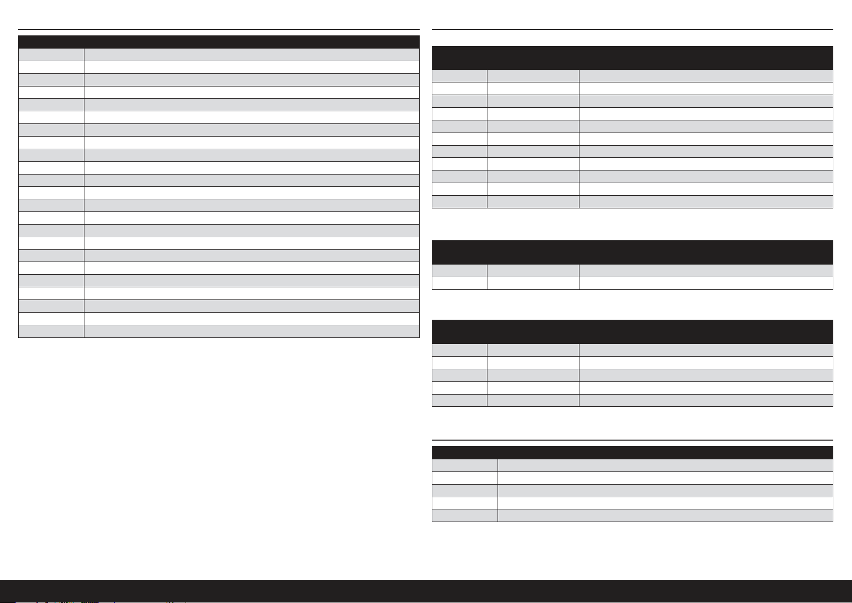
ERSATZEILE ZUR FERTIGSTELLUNG ERFORDERLICH
Teile-Nr. Beschreibung
EFLG630S Elektrische Einfahrvorrichtung
HAN318501 Rumpf
HAN318502 Linke Innentragfläche
HAN318503 Rechte Innentragfläche
HAN318504 Linke Außentragfläche
HAN318505 Rechte Außentragfläche
HAN318506 Linkes Winglet
HAN318507 Rechtes Winglet
HAN318508 Räder Flügelspitze
HAN318509 Höhenruder
HAN318510 Tragflächensteckung aus Kohlenstoff
HAN318511 Gestänge Außentragfläche
HAN318512 Winglet-Steckungen
HAN318513 Servo-Abdeckungen (6)
HAN318514 Cockpit
HAN318515 Sitz
HAN318516 Seitenleitwerk
HAN318517 Fahrwerkteile
HAN318518 Fahrwerkklappen
HAN318519 Spornrad
HAN318520 Aufhängungen (4)
HAN318521 Bremsklappen-Abdeckungen (2)
HAN318522 Tragflächenhalterungen (2)
Alle Versionen
Erforderliche
Anz.
1 SPMAR12310T AR12310T PowerSafe Tele RX mit 12 Kanälen
4 SPMSA5060 A5060 H-T/H-S HV-Mini-Metall-Servo
2 SPMSA7050 A7050 HV dünne Tragfläche MG hoher Drehzahl
3 SPMA3003 Servokabelverlängerung 300 mm
8 SPMA3004 Servokabelverlängerung 460 mm
5 SPMA3005 Servokabelverlängerung 600 mm
4 SPMA3007 Servokabelverlängerung 1200 mm
1 SPMA3008 Heavy Duty Y-Kabelbaum, 150 mm
2 SPMB4000LPRX LiPo-Empfängerakku (7,4 V / 4000 mAh)
1 SPMA3054 Servosteckerklemmen (25)
1 SPMVR5203 VR5203 dualer Leistungsregler
Antriebslose Version für Schleppstart
Erforderliche
Anz.
1 SPMSA7040 A7040 HV Einfahr-Servo
Elektrisch angetriebene Version
Erforderliche
Anz.
1 CSE010009700 Talon 90 A 25 V bürstenloser Geschwindigkeitsregler mit 20 A BEC
1 EFLM4060B Bürstenloser Außenläufer-Motor Leistung 60, 470Kv
1 EFLP16080FA Spinner, 45mm: ASW 20 4,7m
1 HAN495512 Propeller 16 x 10: ASW 20 4,7m
1 KXSB40006S40 F-Tek 4000mA 6S 40C, EC5, LED
Teile-Nr. Beschreibung
Teile-Nr. Beschreibung
DLMBD38 Liquid Gravity-Ballastkugeln; Gewichtssystem
Teile-Nr. Beschreibung
OPTIONALE TEILE
Teile-Nr. Beschreibung
SPMA3008 Heavy Duty Y-Kabelbaum, 150 mm
SPMAS3000 AS3000 AS3X Stabilisierungsmodul
TAM85013 Sprühlack TS-13 Klar
TAM86024 PS-24 Neon-Orange 100ml Sprühdose
TAM87044 Grundierung Weiß 180ml
42DE
Page 43
REMARQUE
La totalité des instructions, garanties et autres documents est sujette à modification à la seule discrétion d’Horizon
Hobby, LLC. Pour obtenir la documentation àjour, rendez-vous sur le site horizonhobby.com et cliquez sur l’onglet de
support de ce produit.
SIGNIFICATION DE CERTAINS TERMES SPÉCIFIQUES
Les termes suivants sont utilisés dans l’ensemble du manuel pour indiquer différents niveaux de danger lors de
l’utilisation de ce produit:
AVERTISSEMENT: Procédures qui, si elles ne sont pas suivies correctement, peuvent entraîner des dégâts matériels
et des blessures graves OU engendrer une probabilité élevée de blessure superficielle.
ATTENTION: Procédures qui, si elles ne sont pas suivies correctement, peuvent entraîner des dégâts matériels ET des
blessures graves.
REMARQUE: Procédures qui, si elles ne sont pas suivies correctement, peuvent entraîner des dégâts matériels ET
éventuellement un faible risque de blessures.
AVERTISSEMENT: Lisez la TOTALITÉ du manuel d’utilisation afin de vous familiariser avec les caractéristiques du
produit avant de le faire fonctionner. Une utilisation incorrecte du produit peut entraîner sa détérioration, ainsi que
des risques de dégâts matériels, voire de blessures graves.
Ceci est un produit de loisirs sophistiqué. Il doit être manipulé avec prudence et bon sens et requiert des aptitudes
de base en mécanique. Toute utilisation irresponsable de ce produit ne respectant pas les principes de sécurité peut
provoquer des blessures, entraîner des dégâts matériels et endommager le produit. Ce produit n’est pas destiné à
être utilisé par des enfants sans la surveillance directe d’un adulte. N’essayez pas de modifier ou d’utiliser ce produit
avec des composants incompatibles hors des instructions fournies par Horizon Hobby, LLC. Ce manuel comporte des
instructions relatives à la sécurité, au fonctionnement et à l’entretien. Il est capital de lire et de respecter la totalité
des instructions et avertissements du manuel avant l’assemblage, le réglage et l’utilisation, ceci afin de manipuler
correctement l’appareil et d’éviter tout dégât matériel ou toute blessure grave.
CONSIGNES DE SÉCURITÉ CONCERNANT L’UTILISATION
• Inspectez votre modèle avant chaque vol.
• Surveillez les fréquences utilisées à proximité.
• Soyez toujours courtois et respectueux des autres utilisateurs de la zone de vol.
• Choisissez une zone dégagée de tout obstacle et suffisamment grande pour voler en toute sécurité.
• Contrôlez que la zone est libre de spectateurs avant de lancer votre modèle.
• Soyez conscient des autres activités aux alentours de votre vol, risque de conflit potentiel.
• Planifiez votre vol avant de le commencer.
AVANT DE COMMENCER L’ASSEMBLAGE
• Retirez toutes les pièces des sachets pour les inspecter.
• Inspectez soigneusement le fuselage, les ailes et les empennages.
• Si un élément est endommagé, contactez votre revendeur.
• ll est recommandé de préparer tous les éléments du système de la radio.
• Cela inclut la charge des batteries comme la mise au neutre des trims et des manches de votre émetteur.
• Si vous utilisez une radio programmable, sélectionnez une mémoire libre afin d’y enregistrer les paramètres de ce
modèle.
• Nous vous recommandons d’affecter maintenant le récepteur à l’émetteur en suivant les instructions fournies avec
votre radio.
REMARQUE: Reconnectez le système radio une fois que tous les coudes de contrôle sont configurés. Cette action
empêche les servos de se déplacer vers leurs extrémités jusqu’à la connexion de l’émetteur et du récepteur. Cela
garantit aussi que les paramètres d’inversion du servo sont enregistrés dans le système radio.
14 ANS ET PLUS. CECI N’EST PAS UN JOUET.
AVERTISSEMENTS RELATIFS À LA SÉCURITÉ
Lisez et suivez toutes les instructions relatives à la sécurité avant utilisation. Une utilisation inappropriée peut entraîner
un incendie, de graves blessures et des dégâts matériels.
Composants
Utilisez uniquement des composants compatibles. Si vous avez des questions concernant la compatibilité, référez-vous
à ce manuel ou contactez le service technique Horizon Hobby.
Le vol
Volez uniquement dans des zones dégagées pour un maximum de sécurité. Il est recommandé d’utiliser les pistes des
clubs d’aéromodélisme. Consultez votre mairie pour connaître les sites autorisés.
L’hélice
Gardez éloignés tous les éléments qui pourraient être attrapés par l’hélice. Cela inclut les vêtements larges ou les
objets comme des outils par exemple. Gardez toujours vos mains à distance pour éviter tout cas de blessures.
Les batteries
Suivez toujours les instructions du fabricant de vos batteries. Une mauvaise manipulation d’une batterie Li-Po peut
entraîner un incendie causant de graves dégâts matériels et des blessures corporelles.
Petites pièces
Ce kit contient des petites pièces qui ne doivent pas être laissées à la portée des enfants, ces pièces sont dangereuses
pour eux et peuvent entraîner de graves blessures.
ASH 31 6.4M ARF
43 FR
Page 44
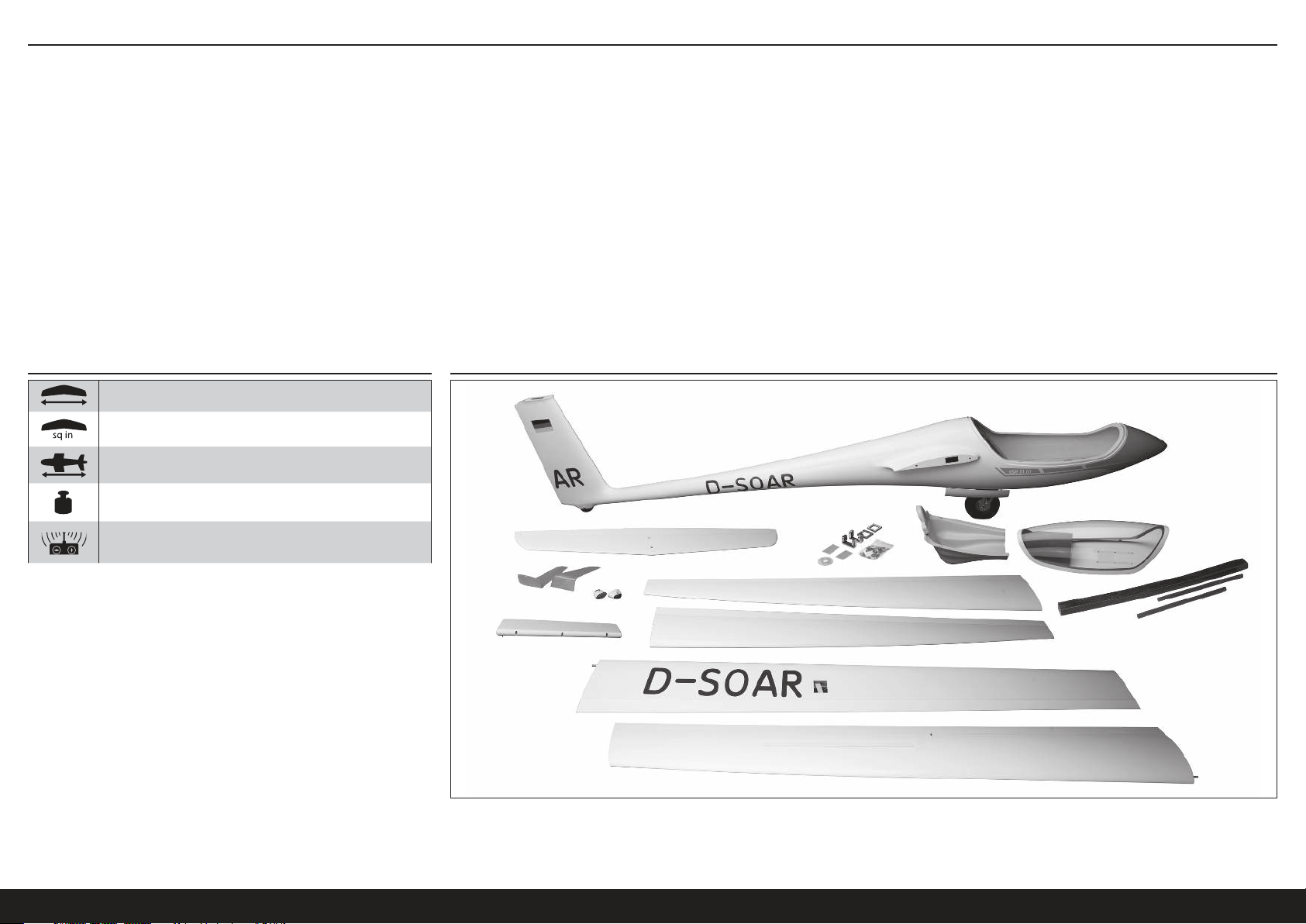
TABLE DES MATIÈRES
Remarque ..............................................................................................................................................................43
Signification de certains termes spécifiques ..........................................................................................................43
Avant de commencer l’assemblage .......................................................................................................................43
Spécifications ........................................................................................................................................................44
Grandes Pièces ......................................................................................................................................................44
Requis pour la finition ............................................................................................................................................45
Éléments Optionnels ..............................................................................................................................................45
Éléments supplémentaires requis ..........................................................................................................................45
Aucun outil n’est nécessaire ..................................................................................................................................45
Précautions de construction ...................................................................................................................................46
Transport et stockage ............................................................................................................................................46
Entretien de la couleur fluorescente .......................................................................................................................46
Panneaux d’ailes externes .....................................................................................................................................46
Panneaux d’ailes internes ......................................................................................................................................48
Installation d’ailette................................................................................................................................................51
Installation de la gouverne de direction ..................................................................................................................51
Installation de l’élévateur ....................................................................................................................................... 53
SPÉCIFICATIONS GRANDES PIÈCES
6,4m (252po)
123,87 dm2 (1920 po carré)
2,2m (88po)
Installation du dégagement de la remorque ...........................................................................................................54
Installation de la radio ............................................................................................................................................54
Installation du cockpit ............................................................................................................................................55
Installation du système électrique optionnel ...........................................................................................................55
Assemblage final ...................................................................................................................................................58
Équilibrage de l’appareil ........................................................................................................................................59
Débattements ........................................................................................................................................................60
Checklist d’avant vol ..............................................................................................................................................60
Contrôles systématiques ........................................................................................................................................60
Garantie et réparations ..........................................................................................................................................60
Coordonnées de Garantie et réparations ................................................................................................................61
Informations de conformité pour l’Union européenne .............................................................................................61
Instructions relatives àl’élimination des D3E pour les utilisateurs résidant dans l’Union Européenne .....................61
Pièces De Rechange ..............................................................................................................................................62
Requis pour la finition ............................................................................................................................................62
11,8 kg (26 livres)
6 canaux (ou plus) avec 7 servos
44FR
Page 45

REQUIS POUR LA FINITION
Toutes les versions
Nombre
requis
1 SPMAR12310T PowerSafe Tele RX 12canaux AR12310T
4 SPMSA5060 Mini-servo métallique A5060 H-T / H-S HV
2 SPMSA7050 A7050 HV Aile fine Hi Torq MG
3 SPMA3003 Rallonge de servo, 300 mm
8 SPMA3004 Rallonge de servo, 460 mm
5 SPMA3005 Rallonge de servo, 600 mm
4 SPMA3007 Rallonge de servo, 1200 mm
1 SPMA3008 Harnais résistant en Y de 150 mm
2 SPMB4000LPRX Batterie Li-Po de récepteur 7,4 V 4000 mAh
1 SPMA3054 Attaches de connexion du servo (25)
1 SPMVR5203 Régulateur à double sortie VR5203
Version sans moteur, lancée par remorque
Nombre
requis
1 SPMSA7040 Servo à rétractation A7040 HV
Version électrique
Nombre
requis
1 CSE010009700 Variateur ESC Talon 90 A 25 V BL avec BEC 20 A
1 EFLM4060B Moteur à cage tournante sans balais Power 60 de 470Kv
1 EFLP16080FA Cône, 45mm: ASW 20 4,7m
1 HAN495512 Hélice 16 x 10: ASW 20 4,7m
1 KXSB40006S40 F-Tek 4000mAh 6S 40C, EC5, LED
Référence Description
Référence Description
DLMBD38 Liquid Gravity; système de lestage
Référence Description
ÉLÉMENTS OPTIONNELS
Référence Description
SPMA3008 Harnais résistant en Y de 150 mm
SPMAS3000 Module de stabilisation AS3000 AS3X
TAM85013 Vaporisateur de laque TS-13 transparente
TAM86024 Aérosol PS-24 Fluor Org 100ml
TAM87044 Apprêt blanc 180ml
ÉLÉMENTS SUPPLÉMENTAIRES REQUIS
Description
Émetteur à 6+ canaux
Chargeur de batterie Li-Po
AUCUN OUTIL N’EST NÉCESSAIRE
Description
Support d’équilibrage
Clé hexagonales: 17mm
Pinces
Ruban adhésif transparent
Pince à sertir
Colle cyanoacrylate (CA), mince et moyenne
Percez avec diverses tailles de mèches
Époxy
Pinceau Epoxy
Feutre fin effaçable
Alcool isopropylique
Pince Hemostat
Hex drivers, metric, various sizes
Couteau : Lame numéro 11
Longue barre de liaison en plastique
Ruban de masquage à faible adhérence
Papier à poncer grain moyen
Règle métrique
Microballons
Récipients pour mélanger et bâtons
Papier absorbant
Crayon à papier
Tournevis cruciforme: #1, #2
Porte forets
Pince
Outil rotatif avec disque de découpe, ponceuse à tambour, couteau de carbure, meule à aiguiser
Fer à souder et fil à souder
Ficelle
ASH 31 6.4M ARF
45 FR
Page 46
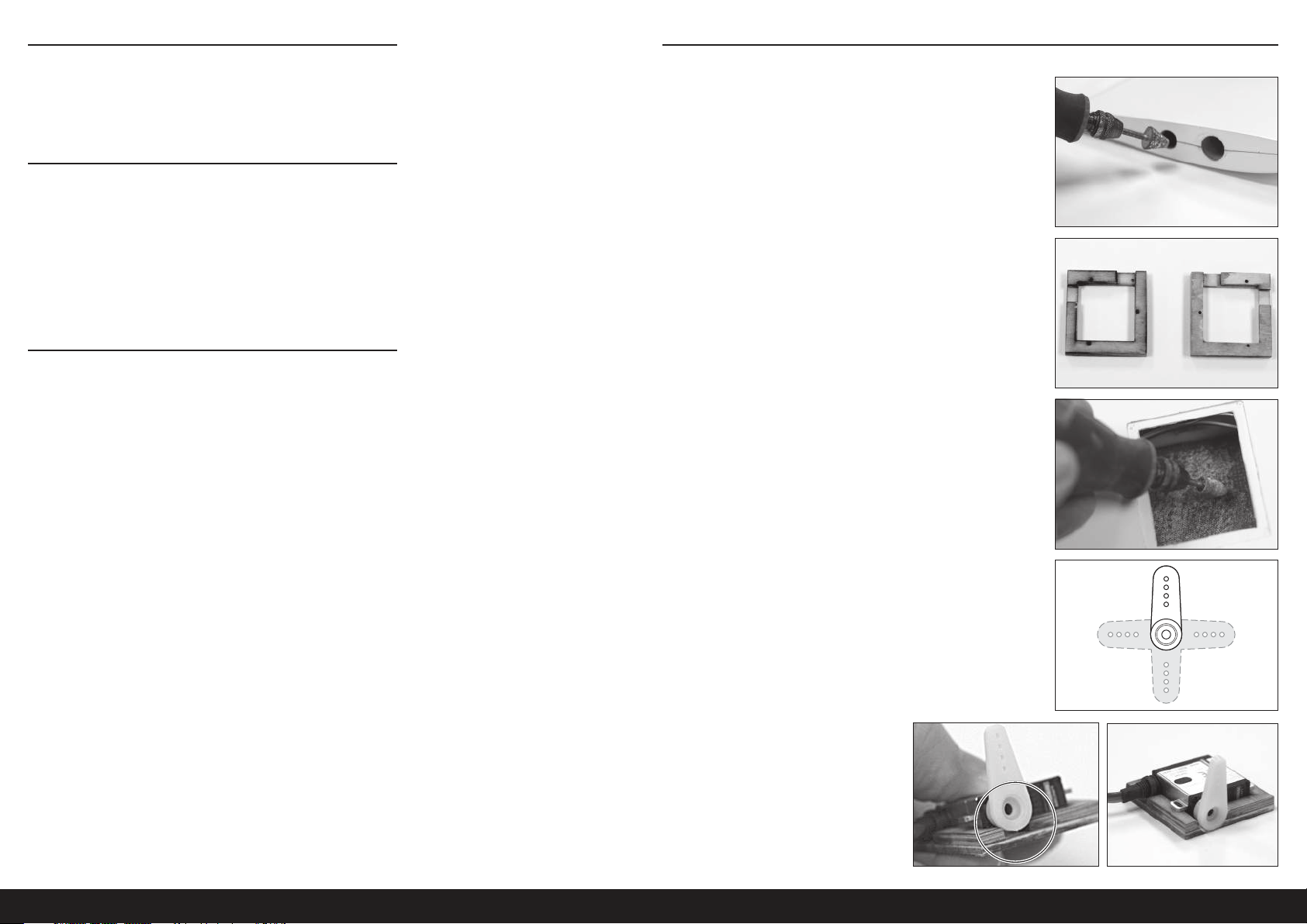
PRÉCAUTIONS DE CONSTRUCTION
Préparez la surface de travail avant le début de la construction.
La surface devrait être douce et sans aucun objet pointu. Nous
recommandons de poser les pièces du fuselage sur une serviette
douce ou du pit mat pour empêcher les éraflures ou les bosses sur la
surface de l’appareil.
TRANSPORT ET STOCKAGE
Lorsque vous transportez et stockez votre modèle, vous devez avoir
au minimum un espace de 2m (80po) de longueur et 46cm (18po)
de hauteur pour la taille du fuselage. Nous vous conseillons d’utiliser
des sacs d’ailes et de stabilisateurs pour protéger ces surfaces lors
du transport et du stockage. Les renvois de commande et tringleries
peuvent également endommager les autres surfaces même s’ils sont
rangés dans des sacs de stockage. Transportez et stockez toujours
les ailes et le stabilisateur afin que les tringleries ne touchent pas les
autres panneaux, pour empêcher les dommages.
ENTRETIEN DE LA COULEUR FLUORESCENTE
La couleur fluorescente utilisée sur votre modèle peut se décolorer
avec le temps en cas d’exposition directe au soleil. Pour augmenter la
longévité de la couleur fluorescente sur l’appareil, limitez l’exposition
directe au soleil lorsque vous ne volez pas.
Si des réparations deviennent nécessaires ou si vous décidez de
colorer les pièces facultatives afin de correspondre à la couleur du
fuselage, la couleur pulvérisée Tamiya, PS-24, Orange Fluorescent,
correspond très bien à la couleur utilisée sur le modèle. Pour de
meilleurs résultats, le PS-24 doit être pulvérisé au-dessus de l’apprêt
blanc fin Tamiya (TAM87044) et recouvert par du Tamiya TS-13,
transparent.
PANNEAUX D’AILES EXTERNES
1. Retirez le ruban d’emballage, nettoyez et polissez la surface d’aile.
2. Découpez un trou d’accès à l’extrémité racine du panneau d’aile
externe en utilisant un outil rotatif.
CONSEIL: Faites le trou juste assez large pour que le
connecteur du servo puisse passer à travers. Si le trou est trop
grand, l’extension retombera dans le panneau d’aile lors du
débranchement.
3. Trouvez les supports de servos courts. Percez des trous de guidage
pour les vis de montage du servo.
4. Rendez soigneusement rugueuse la surface de montage du servo
d’aile pour le support de servo en utilisant un outil rotatif à faible
vitesse ou du papier abrasif de grain 80. Poncez légèrement
seulement la surface interne du panneau d’aile pour donner de
l’adhérence à l’époxy. NE poncez PAS la surface du panneau
d’aile. Nettoyez la surface de montage soigneusement avec de
l’alcool dénaturé ou à 91% IPA.
5. Découpez 3 bras d’un renvoi de commande à 4 bras.
6. Vérifiez l’ajustement du servo avec le bras de servo
installé. Agrandissez l’ouverture du support si nécessaire
pour permettre au servo de se fixer entièrement dans le
support.
Vérifiez aussi l’ajustement des vis de support du servo
pour vous assurer qu’elles ne dépassent pas le support et
qu’elles n’endommagent pas la surface d’aile. Si les vis
dépassent, découpez-les pour qu’elles soient en dessous
de la surface du support.
46FR
Page 47
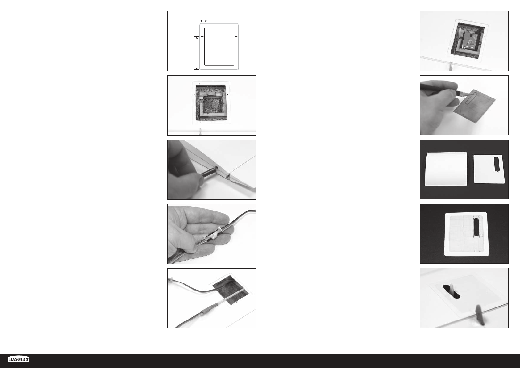
7. Mesurez et marquez le panneau d’aile à la trappe de servo; à
10mm du bord relevé de la trappe externe et à 45mm du bord
relevé arrière.
En montant le cadre dans l’aile, le bord du châssis s’aligne avec
les marques avant et arrière, et la sortie du servo s’aligne avec la
marque de 45mm.
45mm
10mm
12. Installez le bras de servo. Installez le servo dans le support en
utilisant les vis courtes de servo (2 x 8mm).
8. En utilisant de l’époxy (DLMAD64), installez le support de
servo sur le panneau d’aile. Assurez-vous que le bras de servo
s’alignera avec le renvoi de commande de surface. L’encoche
d’espacement du bras devrait être tournée vers l’extrémité de
l’aile et l’encoche du fil de servo devrait être tournée vers l’avant.
Nettoyez tout l’époxy de la zone de montage du servo, qui pourrait
interférer avec l’ajustement du servo dans le support, avec du
papier absorbant et de l’alcool. Laissez la colle époxy sécher
complètement.
9. Installez les goupilles anti-rotation dans l’extrémité racine avec
l’époxy. Ne poussez pas la goupille vers l’intérieur de plus de la
moitié de sa longueur. Nettoyez tout l’époxy en excès avec du
papier absorbant et de l’alcool.
10. Raccordez une extension du fil de servo de 304mm (12po) au
servo de l’aileron. Fixez l’extension avec l’attache de connexion de
servo (SPMA3054) ou le tube thermorétractable.
11. Utilisez soit un fil avec un poids attaché ou une longue barre de
liaison en plastique pour fileter l’extension du servo assemblé à
travers le panneau d’aile et hors du trou d’accès précédemment
découpé.
CONSEIL: Faites passer le fil ou la barre en plastique à travers
le trou d’accès vers la trappe du servo et fixez le fil du servo à
l’extrémité. Tirez l’extrémité du fil de servo vers l’arrière à travers
le trou d’accès.
13. Mesurez soigneusement et découpez un trou dans la trappe pour
le bras de servo en utilisant un outil rotatif ou un couteau Hobby.
Vérifiez souvent l’ajustement de la trappe afin de vous assurer
que l’espacement est approprié pour le bras de servo à travers la
course complète du servo. Arrondissez les coins extérieurs de la
trappe pour un ajustement complet dans la zone de montage en
cavité dans le panneau d’aile.
14. Découpez un morceau de film adhésif blanc UltraTrim
(HANU80000) environ 3cm plus large que la taille de la trappe du
servo.
15. Détachez le film adhésif et collez-le à la partie finie de la trappe de
servo.
CONSEIL: Commencez au centre de la trappe et appuyez
soigneusement sur toutes les bulles d’air et les faux-plis hors du
film en progressant vers les bords.
Découpez et retirez le trou pour le bras de servo. Découpez le film
pour dépasser d’environ 10mm le bord de la trappe et arrondissez
les coins comme illustré, pour aider à empêcher que les coins se
soulèvent après l’utilisation.
16. Installez soigneusement la trappe de servo sur le panneau d’aile en
plaçant la trappe dans la cavité du panneau d’aile et en appuyant
sur le film vers le panneau d’aile, autour du périmètre de la trappe.
Progressez vers l’extérieur de la trappe pour retirer toutes les
bulles d’air et les faux-plis.
ASH 31 6.4M ARF
47 FR
Page 48
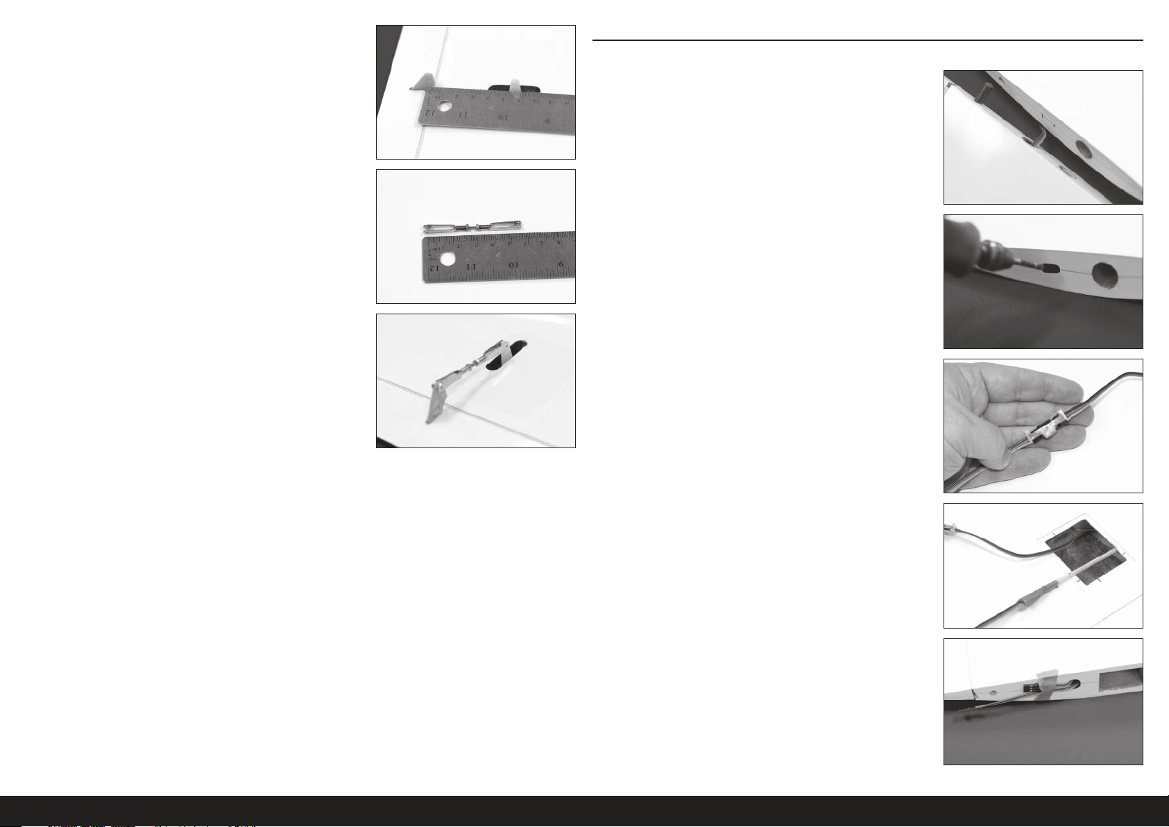
17. Avec l’aileron maintenu au centre, mesurez entre les trous du bras
de servo et du renvoi de commande.
18. Fixez la longueur de la barre de liaison de l’aileron selon la mesure
ci-dessus, en tournant la manille vers l’intérieur ou l’extérieur
à l’une des extrémités de la barre de liaison. Lorsque la bonne
longueur est atteinte, appliquez un composé pour frein-filet et
serrez les écrous contre la manille. Essayez de centrer la barre
filetée entre les deux manilles.
CONSEIL: Il faudra peut-être découper la barre filetée en excès,
si vous le souhaitez. Laissez assez de barre pour qu’au moins 3
filetages soient visibles à l’intérieur de la manille, comme indiqué.
19. Installez la barre de liaison sur le servo et les renvois de
commande de surface. Assurez-vous que la surface de commande
est centrée lorsque le servo est en position neutre.
PANNEAUX D’AILES INTERNES
1. Retirez le ruban d’emballage, nettoyez et polissez la surface d’aile.
2. Posez le panneau d’aile externe fini à côté du panneau d’aile
interne, comme indiqué. Marquez l’emplacement du trou d’accès
de l’aile externe sur le panneau d’aile interne.
3. Découpez les trous d’accès à l’extérieur et aux extrémités racines
du panneau d’aile interne. Les trous doivent être juste assez larges
pour faire passer les connecteurs de servo, afin d’empêcher les
extrémités de tomber dans l’aile.
4. Connectez une extension de servo de 122cm (48po) et 61cm
(24po) ensemble pour créer une extension d’aileron interne. Fixez
avec une attache ou un tube thermorétractable.
20. Répétez les étapes 1 à 19 pour le panneau d’aile externe opposé.
5. Insérez une longue barre de liaison en plastique ou un fil lesté
à travers le trou d’accès découpé dans une des extrémités
du panneau et hors de la trappe du servo du volet. Fixez une
extrémité de l’extension du servo d’aileronassemblé à la barre de
liaison. Tirez l’extrémité de l’extension à travers le panneau d’aile
et hors du trou d’accès. Avec du ruban adhésif, collez l’extrémité
de l’extension à l’extrémité du panneau d’aile.
Répétez la procédure à partir de l’autre extrémité du panneau afin
de tirer l’extrémité opposée de l’extension du servo d’aileronà
travers le trou d’accès dans l’autre extrémité du panneau d’aile.
48FR
Page 49
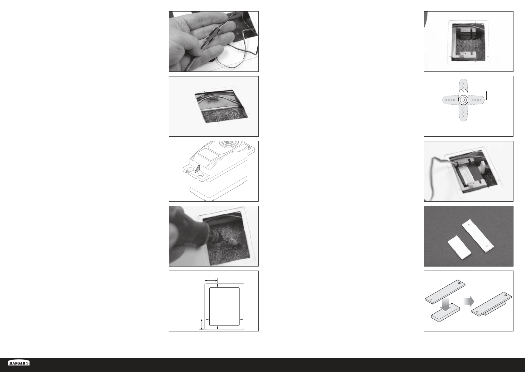
10mm
6. Connectez une extension de servo de 45cm (18 po) au
fil de déporteur et fixez-la avec une attache ou un tube
thermorétractable. Filetez l’extension à travers l’extrémité interne
du panneau d’aile, comme précédemment.
11. Installez le support du servo de volet en utilisant de l’époxy. Alignez
le support avec les marques effectuées à l’étape précédente.
Retirez tout l’époxy rentré dans les fentes des languettes de
montage ou à la base interne du support, qui pourrait interférer
avec le servo. Assurez-vous que le support adhère au longeron
et à la surface et que le bras de servo s’aligne avec le renvoi de
commande du volet. Laissez la colle époxy sécher complètement.
7. En utilisant de le colle thermofusible ou de la colle de contact,
comme Deluxe Systems Foam2Foam (DLMAD34), fixez les fils
du déporteur et de l’aileron au longeron à l’avant de la trappe du
servo. Cela empêchera les fils de se décaler et d’interférer avec le
bras de servo du volet et la barre de liaison.
8. Découpez soigneusement les bandes sur les languettes de
montage du servo. Vérifiez l’ajustement du servo dans le support
du servo. Le servo devrait être très bien ajusté dans le support.
9. Poncez soigneusement la surface de montage du servo de volet
d’aile pour le support de servo en utilisant un outil rotatif à faible
vitesse ou du papier abrasif de grain 80. Poncez légèrement
seulement la surface interne du panneau d’aile pour donner de
l’adhérence à l’époxy. NE poncez PAS la surface du panneau
d’aile. Nettoyez la surface de montage soigneusement avec de
l’alcool dénaturé ou à IPA.
12. Découpez le bras de servo du volet à la longueur.
13. Centrez le servo et installez le renvoi de commande orienté
légèrement vers le bord de fuite de l’aile.
14. Glissez le servo dans le support comme indiqué.
15. En utilisant le modèle d’acétate fourni, créez une plaque de
rétention du servo en utilisant le pli de 0,32cm (1/8po) et 0,16cm
(1/16po).
10. Mesurez et marquez l’ouverture de la trappe du servo de volet, à
12mm de la ligne de cavité arrière et à 17mm de ligne de cavité
externe, comme illustré.
ASH 31 6.4M ARF
17mm
12mm
49 FR
Page 50
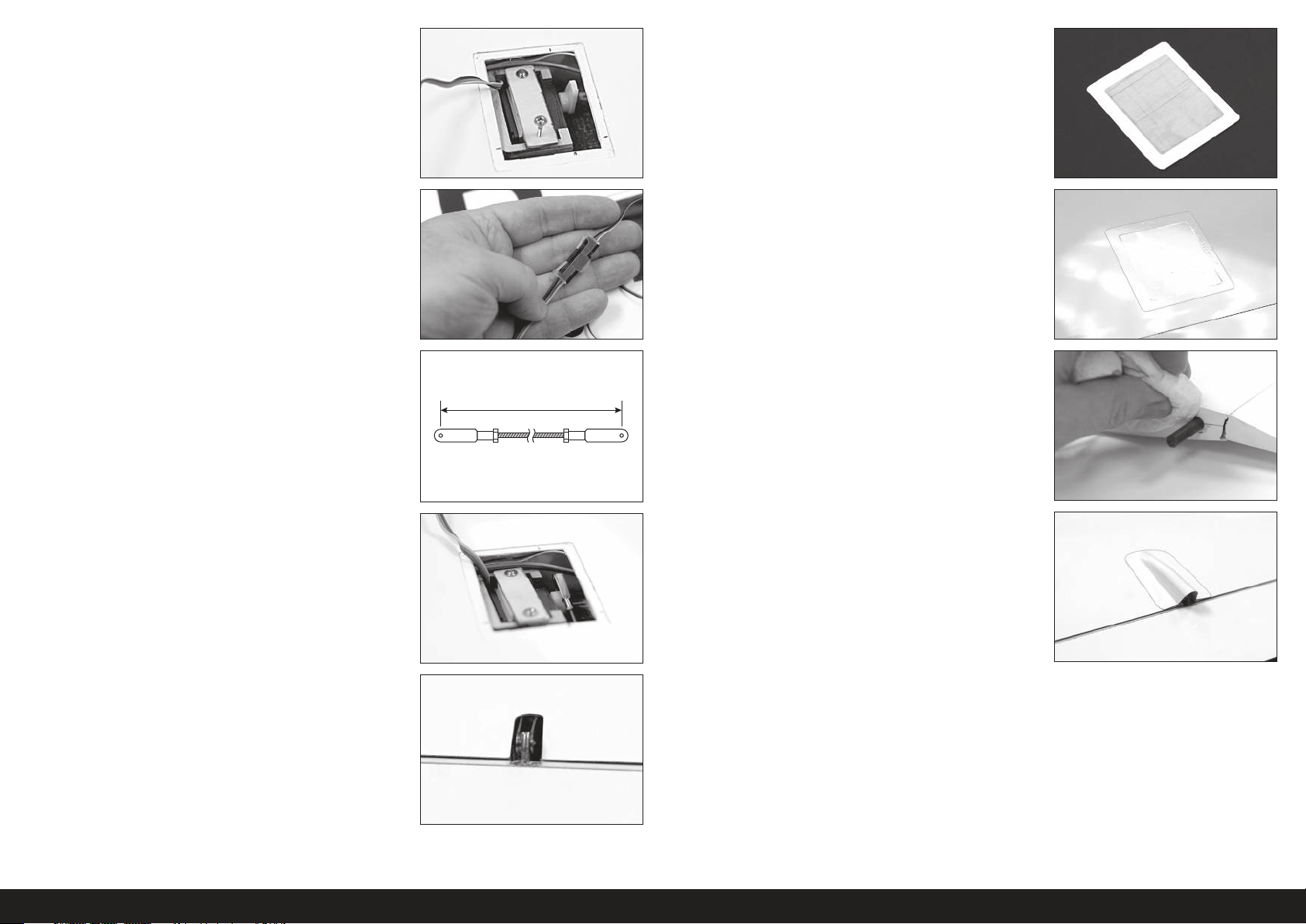
79mm
16. Fixez le servo dans le support avec la plaque de rétention du servo
et deux vis. Assurez-vous que les têtes de vis sont placées en
dessous de la surface de montage de la trappe du servo et que les
vis n’endommagent pas la surface externe du panneau d’aile.
17. Connectez une extension de servo de 45cm (24 po) au fil de servo
et fixez-la avec une attache ou un tube thermorétractable. Filetez
l’extension à travers l’extrémité racine d’aile du panneau d’aile,
en utilisant une longue barre de liaison en plastique ou un fil lesté
comme avant.
20. Installez la trappe de servo sur l’aile avec du ruban adhésif
comme pour le panneau d’aile externe.
18. Coupez les barres de liaison à une longueur de 79mm.
19. Installez la barre de liaison sur le renvoi de commande du volet
et le bras de servo. Déviez le volet vers le bas et insérez une
extrémité de la barre de liaison à travers le trou dans le bord de
fuite de l’aile et connectez-la au bras de servo. Connectez l’autre
extrémité de la barre de liaison au renvoi de commande du volet.
21. Installez les goupilles anti-rotation dans l’extrémité racine du
panneau avec l’époxy. Nettoyez tout l’époxy en excès avec du
papier absorbant et de l’alcool.
22. Découpez et fixez la couverture de sortie de la barre de liaison du
volet en haut de l’aile en utilisant de la colle de contact.
23. Répétez les étapes 1 à 22 pour le panneau d’aile interne opposé.
50FR
Page 51
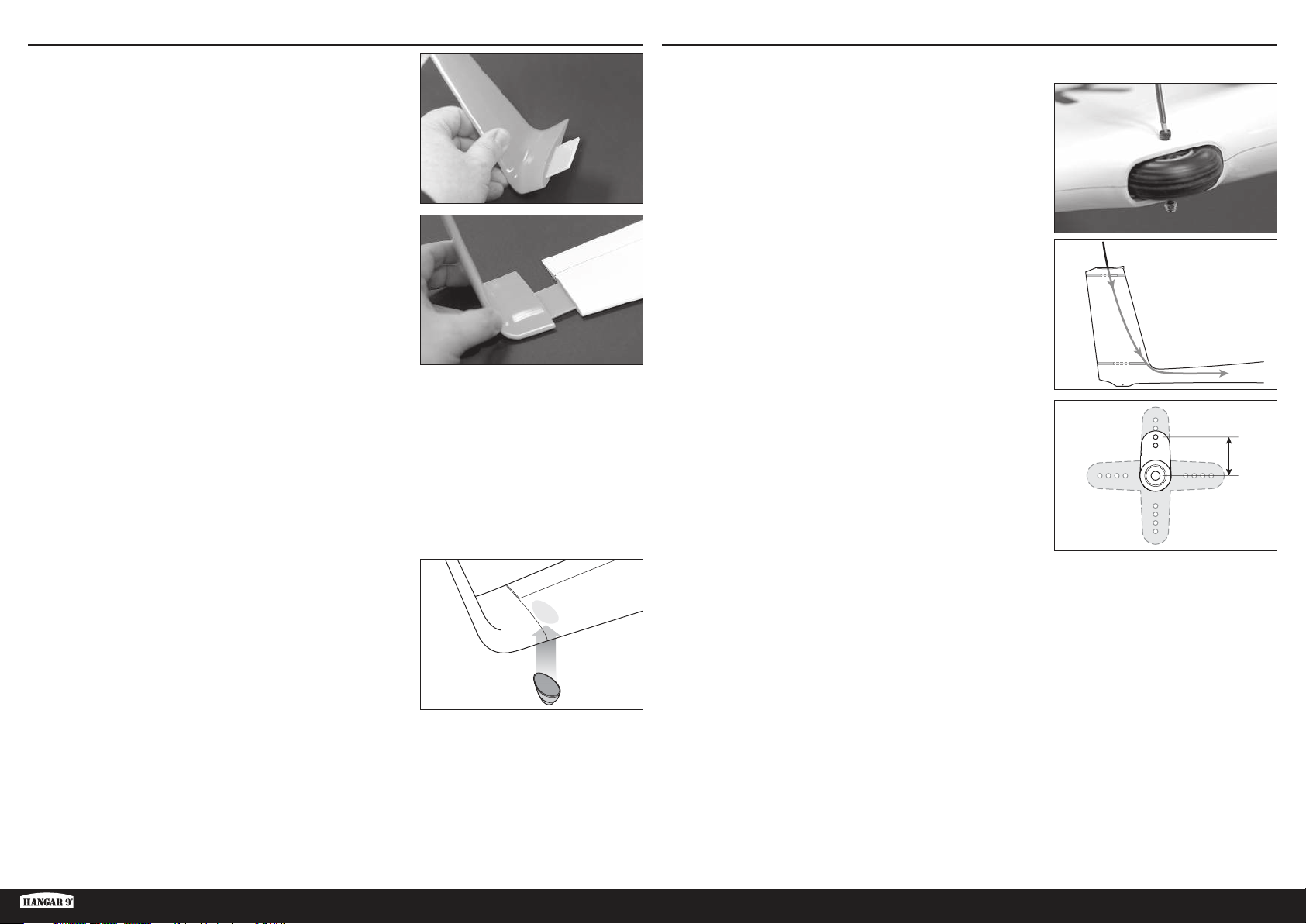
13mm
INSTALLATION D’AILETTE
1. Glissez la lame d’ailette dans la fente d’ailette.
2. Glissez l’ensemble dans la fente de l’extrémité du panneau d’aile
externe.
INSTALLATION DE LA GOUVERNE DE DIRECTION
1. Nettoyez et polissez le fuselage.
2. Retirez la roue de queue à l’aide d’une clé à six pans de 2,5mm.
3. Faites passer un fil lesté ou une longue barre de liaison flexible
à travers l’ouverture du servo de l’élévateur, à travers la dérive
verticale, à travers le petit trou devant l’ouverture du servo de
la gouverne et en haut, à travers la queue du fuselage. Ce sera
utilisé plus tard pour tirer la gouverne et les extensions de servo
d’élévateur à travers le fuselage.
3. Découpez la lame d’ailette à une longueur, si nécessaire,
permettant d’ajuster correctement l’ailette contre le panneau
d’aile. Il ne devrait pas y avoir d’espace entre le panneau et
l’ailette.
4. La lame devrait être bien ajustée à l’ailette et au panneau d’aile
externe. L’ailette devrait être fixée par un ruban adhésif pour plus
de sécurité.
5. En utilisant de l’époxy, fixez une roue du bout d’aile au bas du
panneau d’aile externe, à côté de l’extrémité.
CONSEIL: Utilisez du papier abrasif à grain fin ou une éponge à
récurer pour très légèrement poncer la surface du panneau d’aile
où la roue sera fixée pour donner de l’adhérence à l’époxy.
Répétez les étapes 1 à 5 pour le bout d’aile opposé.
4. Découpez un bras de servo à 13mm.
5. Centrez le servo de la gouverne et installez le bras du servo.
6. Une extension de servo de 152cm (60po) est requise pour le
servo de la gouverne. Raccordez une extension de 230mm
(48po) et de 30cm (12po) au servo de la gouverne. Fixez toutes
les connexions avec les attaches d’extension du servo ou le tube
thermorétractable.
ASH 31 6.4M ARF
51 FR
Page 52
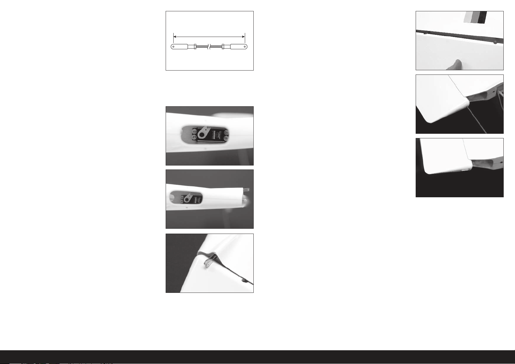
95mm
7. Découpez la barre de liaison de la gouverne afin que la longueur
finie soit de 95mm entre les broches de manille. Fixez une
extrémité de la barre de liaison au bras de servo de la gouverne.
12. Poussez la gouverne au-dessus des points de charnière dans la
dérive.
8. Avec le fuselage à l’envers dans un support, faites passer
l’extension de servo à travers l’encoche du servo de gouverne et
hors de l’encoche du servo de l’élévateur en haut de la dérive. Cette
extension sera tirée à travers le fuselage avec l’extension du servo
de l’élévateur plus tard.
9. Installez le servo de la gouverne à travers l’ouverture de la roue de
queue et dans le support du servo. Le servo est installé avec l’arbre
de sortie vers l’avant de l’appareil et le bras de servo vers le côté
gauche du fuselage. Faites passer l’extrémité ouverte de la barre
de liaison à travers l’ouverture moulée dans la queue lorsque vous
fixez le servo en position. Gardez un peu de tension sur le fil de
servo pour vous assurer que le fil n’est pas pincé à l’ouverture.
CONSEIL: Utilisez un tournevis magnétique ou fixez un petit aimant
à un tournevis normal pour installer les vis du servo.
10. Faites tourner le renvoi de commande du servo afin que la barre de
liaison s’étende hors de l’arrière de la dérive.
11. Fixez le renvoi de commande de la gouverne sur la barre de liaison.
13. Insérez soigneusement l’axe de charnière de la gouverne à travers
le trou en haut de la gouverne et faites-le passer entièrement à
travers chacun des points de charnière jusqu’à ce qu’il sorte du bas
de la gouverne.
CONSEIL: L’axe de charnière est un ajustement par friction serrée.
Il peut être nécessaire de pousser ou tirer légèrement la gouverne
lorsque l’axe est inséré pour être entièrement fixé. Ne pas forcez
pas le passage de l’axe. Si vous sentez de la résistance, déplacez la
gouverne légèrement et continuez à insérer l’axe.
14. Lorsqu’il est entièrement inséré, l’axe de charnière peut être collé
avec du ruban adhésif en haut de la gouverne si vous le souhaitez,
ou si l’axe de charnière est excessivement lâche.
52FR
Page 53
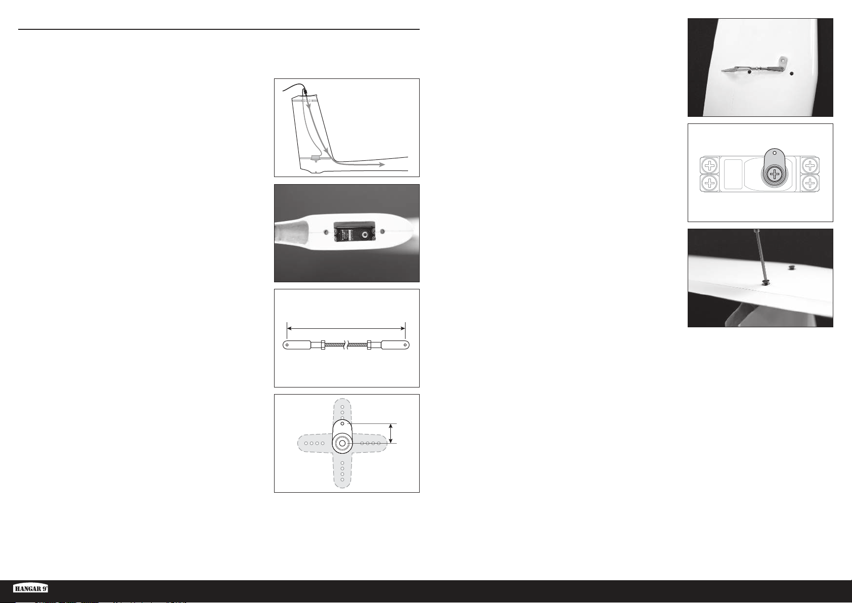
53mm
10mm
INSTALLATION DE L’ÉLÉVATEUR
1. Une extension de servo de 183cm (72po) est requise pour le servo de la gouverne de profondeur. Raccordez
une extension de 122cm (48po) et de 61cm (24po) ensemble et connectez-les au servo de la gouverne de
profondeur. Fixez toutes les connexions avec les attaches ou le tube thermorétractable.
2. Avec du ruban adhésif, collez les extrémités des extensions du
servo de la gouverne et de l’élévateur à la barre de liaison flexible
ou au fil inséré dans le fuselage plus tôt. Tirez soigneusement les
extensions du servo à travers le fuselage et en haut du cockpit.
3. Fixez le servo de l’élévateur en position avec l’arbre de sortie dirigé
vers l’avant de l’appareil. Assurez-vous que le fil du servo n’est pas
pincé.
4. Découpez la barre de liaison de la gouverne de profondeur afin que
la longueur finie soit de 53mm entre les broches de manille. Les
manilles devraient être à 90° l’une de l’autre.
6. Fixez une extrémité de la barre de liaison au bras de servo de
la gouverne de profondeur et l’autre extrémité au renvoi de
commande de l’élévateur.
7. Faites passer la barre de liaison de l’élévateur avec le bras de
servo fixé en haut de la dérive. Centrez le servo de la gouverne de
profondeur. Fixez le renvoi de commande du servo à l’arbre de la
sortie du servo à 90°, comme illustré.
8. Fixez le stabilisateur horizontal à la dérive en utilisant deux vis à
tête plate M4 X 20mm.
5. Découpez le bras de servo de la gouverne de profondeur à 10mm.
ASH 31 6.4M ARF
53 FR
Page 54
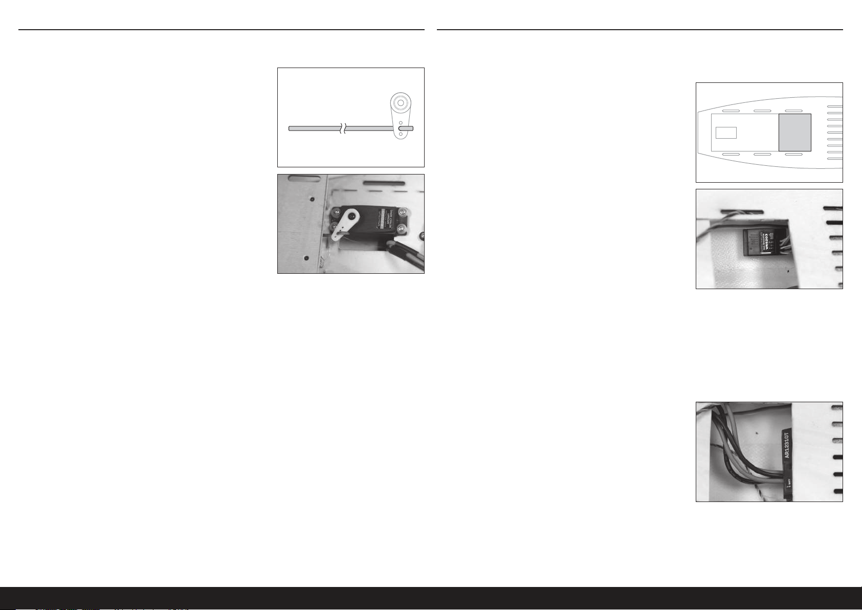
INSTALLATION DU DÉGAGEMENT DE LA REMORQUE INSTALLATION DE LA RADIO
IMPORTANT: Si vous installez l’option électrique, passez cette section
et consultez la section d’installation électrique optionnelle.
1. Installez le fil de dégagement de la remorque sur le bras du servo.
2. Installez le servo de dégagement de la remorque dans le nez du
fuselage. Glissez le fil de dégagement à travers le petit trou à
l’avant du cockpit. Fixez le bras au servo, en vous assurant que le
fil s’ouvre entièrement à une extrémité de la course du servo et se
ferme entièrement à l’opposé de la fin de course.
IMPORTANT: Bien que les déflecteurs et la rentrée fonctionnent à 7,2V, pour une plus grande longévité et fiabilité,
nous recommandons de réguler l’entrée de l’alimentation de ces composants à 5,2V avec l’utilisation d’un régulateur
de tension en ligne, comme SPMVR5203.
Si la rentrée fonctionne lentement ou ne se rétracte pas sur la position entièrement verrouillée à la tension régulée,
faites fonctionner la rentrée directement sur le récepteur à 7,2V.
1. Découpez soigneusement l’arrière du sol du cockpit dans la zone
indiquée.
2. Connectez les canaux d’engrenage et de déflecteur du récepteur
aux ports d’entrée du régulateur.
3. Connectez les ports de sortie du régulateur au fil d’engrenage et
au harnais en Y du déflecteur.
4. Dirigez tous les fils de servo de la queue au fuselage avant, en les
gardant aussi organisés que possible. Utilisez des serre-câbles ou
une bande velcro pour fixer les câbles dans le fuselage.
5. Préparez six fils de servo de 46cm (18po); deux pour les ailerons,
deux pour les volets et deux pour les déflecteurs.
CONSEIL: Utilisez du ruban adhésif coloré différent enroulé autour
des extrémités des fils pour savoir quels fils vont dans quelle
surface de contrôle.
6. Raccordez tous les fils de servos aux ports du récepteur approprié.
7. Montez le récepteur sous l’arrière du sol du cockpit, comme
indiqué. Si nécessaire, utilisez de petits morceaux de mousse ou
de bande velcro pour maintenir le récepteur en place.
CONSEIL: Si vous le souhaitez, découpez des trous dans l’arrière
du sol du cockpit et dirigez les fils du servo vers le récepteur.
8. Montez temporairement les batteries du récepteur aussi à l’avant à l’intérieur du cockpit que possible.
L’emplacement de la batterie sera finalisé après que le bon centre de gravité aura été établi. La version de planeur
sans moteur aura des batteries montées aussi à l’avant que possible, avec un poids du nez supplémentaire.
La version électrique ne nécessite pas de poids du nez supplémentaire pour s’équilibrer, et selon la batterie du
moteur utilisée, nécessitera peut-être que les batteries du récepteur soient déplacées vers l’avant.
54FR
Page 55

INSTALLATION DU COCKPIT
1. Installez la baignoire de cockpit en fibre de verre. Appuyez
doucement sur les côtés de la baignoire pour l’ajuster entre les
côtés du fuselage moulé et en dessous. Les trous dans la baignoire
devraient s’aligner avec les trous dans le fuselage. Il n’est pas
nécessaire de fixer la baignoire sur le fuselage. La baignoire est
amovible pour permettre l’accès à l’arrière du fuselage et la zone
du cockpit inférieur.
INSTALLATION DU SYSTÈME ÉLECTRIQUE OPTIONNEL
1. Rendez rugueuse chacune des pièces du support moteur en
utilisant du papier abrasif de grain 80.
2. Installez le pilote optionnel dans la baignoire pour le réalisme
d’échelle, si vous le souhaitez. Il n’est pas nécessaire de fixer le
pilote sur la baignoire.
CONSEIL: Hangar 9 s’est associé avec deux entreprises qui offrent
des pilotes personnalisés; www.warbirdpilots.com aux États-Unis
et www.tailoredpilots.com au Royaume-Uni offrent des figurines
très détaillées de pilotes qui correspondent à l’ASH 31.
3. Installez la verrière sur le fuselage en insérant la broche à l’avant
de la verrière, dans le trou à l’avant du fuselage et en faisant
tourner l’arrière de la verrière vers le bas contre le fuselage, en
vous assurant que les languettes latérales d’alignement s’insèrent
dans les trous du fuselage.
2. En utilisant de la colle époxy 5minutes, collez les côtés rugueux
des deux pièces de support moteur ensemble, en vous assurant
que les trous s’alignent avec précision. Nettoyez toute la colle
époxy en excès avec de l’alcool et une serviette en papier.
Maintenez les pièces ensemble jusqu’à ce que la colle époxy soit
entièrement séchée.
3. Tracez une ligne autour d’un côté du support à environ 1,5mm du
bord extérieur, comme indiqué.
4. En utilisant la ligne comme guide, poncez un biseau sur le bord du
support en ponçant à travers le bord, du coin arrière à la ligne.
4. Glissez le verrouillage de la verrière à câble, située sous la racine
de l’aile gauche, vers l’intérieur jusqu’à ce que la verrière soit
fixée. Il sera peut-être nécessaire d’appuyer légèrement sur
l’arrière de la verrière pour qu’elle se verrouille entièrement. Le
verrouillage à câble est intentionnellement bien ajusté pour ne pas
se relâcher durant le vol.
ASH 31 6.4M ARF
5. Utilisez du ruban adhésif de 0,32cm (1/8po), marquez une ligne
de 25mm à l’arrière du nez du fuselage.
55 FR
Page 56
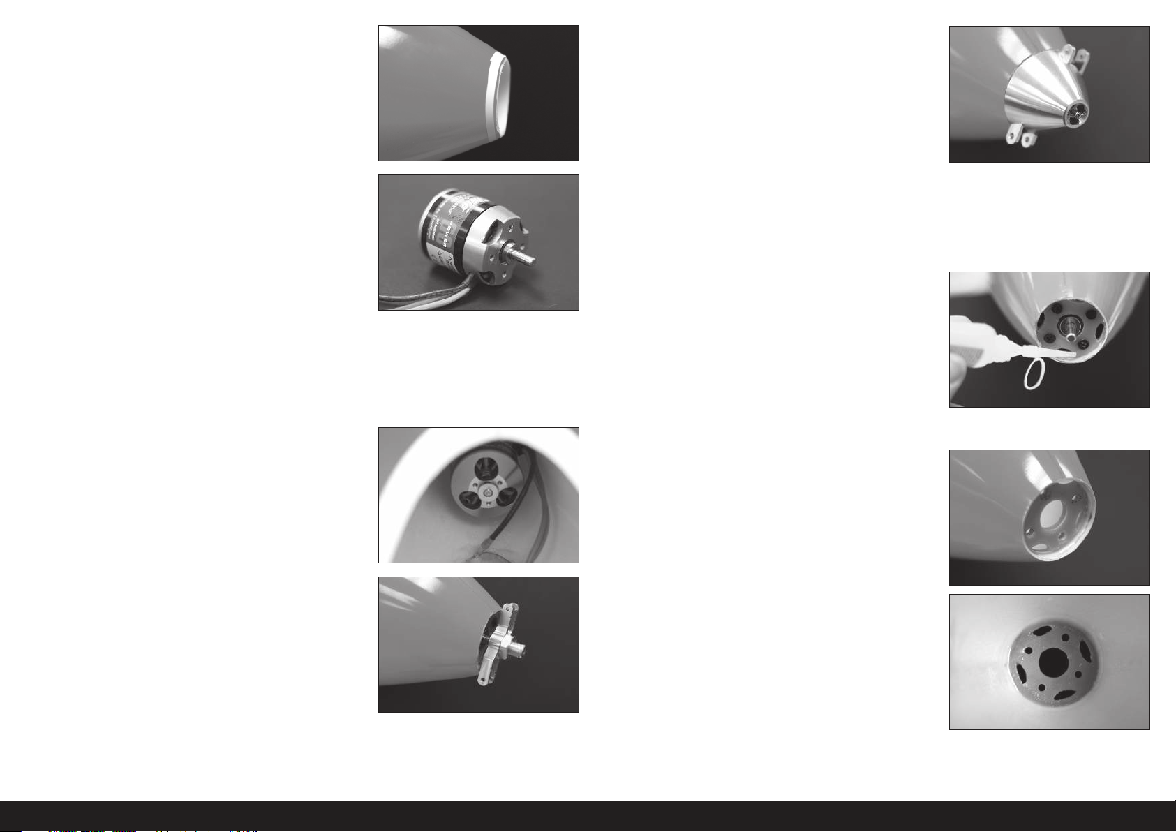
6. Coupez soigneusement le nez loin du fuselage en utilisant un outil
rotatif avec un disque de coupure. Ne coupez pas entièrement
jusqu’au ruban. Laissez un peu d’excès qui sera poncé plus tard.
11. Appuyez sur le moteur vers l’avant et resserrez la vis centrale du
cône tout en appuyant contre le moteur. Resserrez juste assez
la vis pour maintenir le moteur en place mais encore permettre
d’ajuster le placement du cône contre le fuselage.
12. Utilisez le cône pour aligner correctement le moteur avec le nez du
fuselage.
7. En suivant les instructions incluses avec le moteur, changez
l’orientation de l’arbre de moteur pour monter le moteur à l’arrière
du support.
8. Fixez le support moteur sur le moteur à l’aide des vis fournies
avec le moteur. Si nécessaire, utilisez un trou fraisé pour biseauter
des trous dans la plaque de montage. Assurez-vous que le côté
étroit du biseau latéral, précédemment poncé dans le support, est
orienté dans le sens inverse de la position du moteur.
9. Insérez le moteur et le support dans le nez du fuselage de
l’intérieur.
10. Appuyez sur l’adaptateur d’hélice dans l’arbre de moteur et
installez légèrement l’écrou de l’hélice. Installez le cône au-dessus
de l’adaptateur d’hélice. Assurez-vous que le cône est entièrement
fixé au-dessus de l’adaptateur. Installez la vis centrale du cône.
13. Lorsque l’alignement est correct, maintenez solidement le moteur
de l’intérieur du fuselage et retirez soigneusement l’ensemble du
cône en relâchant la vis centrale du cône, en prenant soin de ne
pas déplacer le moteur. Faites glisser l’ensemble du cône hors de
l’arbre du moteur.
14. Avec le cône retiré, collez temporairement le support moteur au
fuselage avec quelques gouttes de colle cyanoacrylate moyenne et
l’accélérateur autour de l’anneau de montage.
15. Retirez les vis du support moteur et le moteur, en prenant soin de
ne pas détacher le support moteur du fuselage.
16. CETTE ÉTAPE EST OBLIGATOIRE. Appliquez une goutte généreuse
d’époxy autour du joint entre le support et le fuselage, à l’avant et
à l’arrière du support moteur. Appuyez sur l’époxy dans le joint et
lissez-le pour former un filet. Avant de continuer, laissez la colle
époxy sécher complètement.
56FR
Page 57
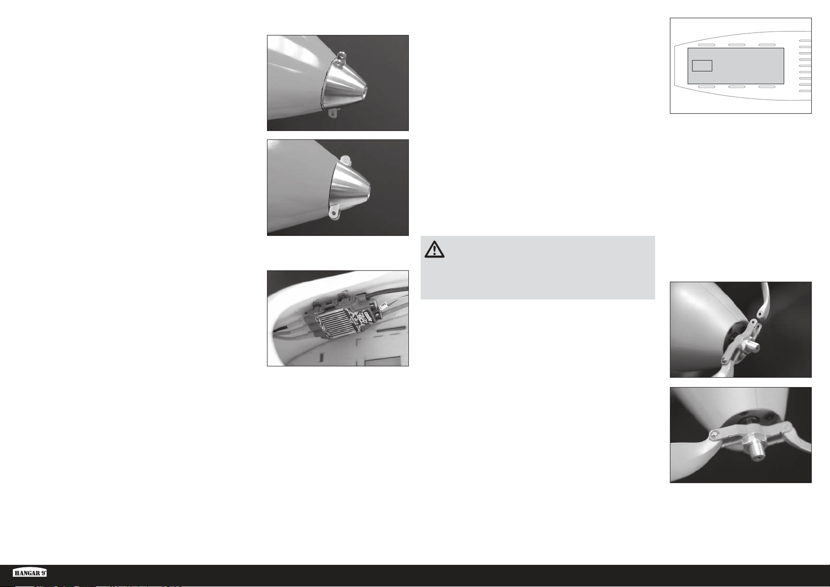
17. Installez temporairement l’ensemble du moteur et du cône.
18. Mesurez et marquez à 1mm à l’arrière du cône autour du
fuselage.
19. Retirez l’ensemble du cône et le moteur et poncez l’avant du
fuselage à l’arrière de la ligne.
CONSEIL: Utilisez un bloc de ponçage pour garder l’avant du
fuselage droit. Retirez le matériel doucement et vérifiez souvent
le progrès. L’objectif est d’obtenir une ligne parfaitement droite
qui est parallèle à l’arrière du cône autour de la circonférence du
fuselage.
24. Découpez et retirez la section du sol de cockpit indiquée.
25. Montez la batterie du moteur dans le sol du cockpit et fixez en
utilisant des bandes velcro à travers les trous prédécoupés dans le
sol du cockpit.
26. Installez les batteries du récepteur à l’arrière du cockpit. Les
batteries du récepteur peuvent être déplacées en conséquence
afin d’ajuster l’équilibre de l’appareil. En utilisant les composants
optionnels du système électrique, aucun lest supplémentaire ne
devrait être requis. Cependant, passez à la section d’équilibrage de
l’appareil pour confirmer que le centre de gravité est correct.
20. Montez le moteur sur le support moteur en utilisant un composé
pour frein-filet à résistance moyenne.
21. Utilisez une bande velcro ou du ruban adhésif pour servo afin
d’installer le variateur ESC dans le cockpit.
22. Connectez les fils du moteur au variateur ESC en suivant les
instructions incluses avec le moteur et le variateur ESC.
23. Connectez le fil des gaz du variateur ESC au port de récepteur
approprié.
ATTENTION: N’essayez jamais de voler sans correctement
équilibrer l’appareil. Un appareil déséquilibré sera
extrêmement instable et peut causer une chute. Les dégâts
consécutifs à une chute ne sont pas pris en charge dans le cadre de
la garantie.
27. Préparez le manche du cône en installant l’arbre conique et
l’écrou. Ne serrez pas l’écrou à ce stade.
28. Vérifiez l’ajustement des lames de l’hélice sur le manche. La lame
devrait bouger librement lorsque l’axe est installé. Sinon, poncez
légèrement les lames où elles touchent le manche pour permettre
le mouvement libre.
29. Une fois que les lames sont ajustées au manche, utilisez les axes
et les attaches pour fixer les lames au manche. Assurez-vous que
l’avant des lames est orienté vers le côté à encoche du manche.
30. Fixez l’ensemble sur l’arbre du moteur. Vérifiez que le manche peut
tourner librement et ne touche pas l’avant du fuselage dans sa
rotation complète. Utilisez une clé de 12mm pour serrer l’écrou,
en fixant le manche et l’adaptateur.
31. Installez le cône, en vous assurant qu’il s’ajuste dans les encoches du manche d’hélice. Utilisez la vis fournie avec
le cône et un tournevis cruciforme n°1 pour fixer le cône à l’adaptateur.
CONSEIL: Le cône et les lames d’hélice peuvent être peintes pour correspondre à l’orange fluorescent du nez de
l’appareil, en utilisant les produits mentionnés dans la section Entretien de la couleur fluorescente, en rendant le
cône et l’hélice presque invisibles durant le vol.
ASH 31 6.4M ARF
57 FR
Page 58
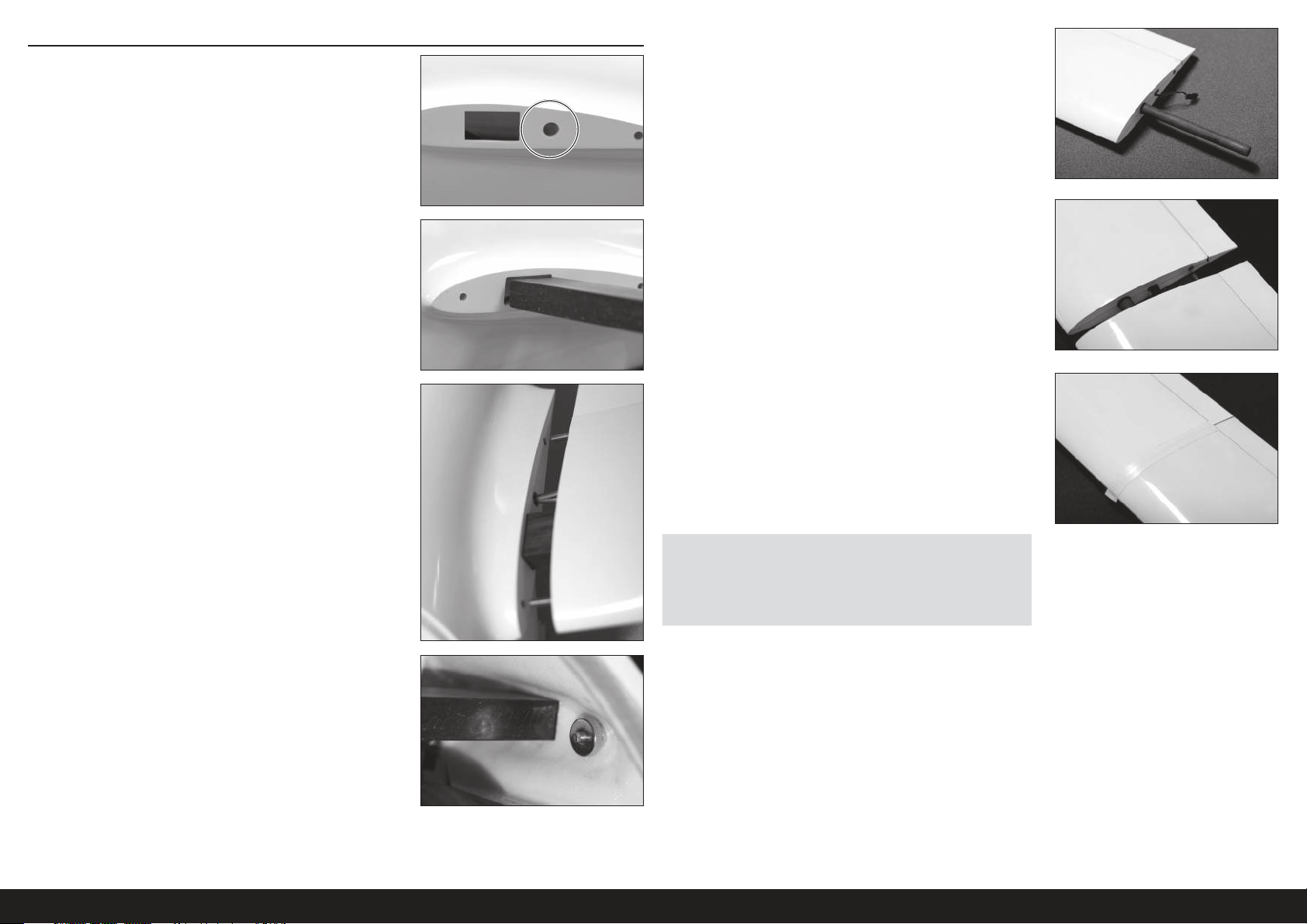
ASSEMBLAGE FINAL
1. Découpez un trou dans l’extrémité d’aile du fuselage pour les
divers fils de servo de l’aile. Assurez-vous que le trou s’aligne
avec le trou précédemment découpé à la racine du panneau d’aile
interne et qu’il est assez large pour permettre aux connecteurs du
fil de servo de passer. Utilisez du papier abrasif pour enlever tous
les bords tranchants autour du trou.
2. Insérez la tige d’aile dans le fuselage. La tige devrait être bien
ajustée dans l’ouverture du fuselage. Assurez-vous que la tige est
centrée dans le fuselage.
5. Faites glisser le tube d’aile externe dans l’extrémité externe du
panneau d’aile interne.
6. Faites glisser les panneaux d’ailes externes au-dessus du tube
d’aile jusqu’à ce que le panneau externe touche le panneau
interne. Assurez-vous que la broche d’alignement de l’aile est
insérée dans le trou d’alignement de l’aile.
3. Faites glisser les panneaux d’ailes internes par-dessus les
extrémités de la tige d’aile, en connectant les fils de servo et en
insérant la broche d’alignement des ailes dans le fuselage, lorsque
vous faites glisser le panneau dessus.
4. Filetez l’écrou de retenue de l’aile sur le piton d’aile fileté de
l’intérieur du fuselage. Serrez l’écrou de retenue à la main, en vous
assurant que les divers fils de servo ne sont pas pincés entre l’aile
et le fuselage.
7. Enveloppez le joint entre le panneau interne et externe avec du
ruban adhésif. Assurez-vous que le ruban adhésif n’interfère
pas avec le fonctionnement des surfaces de contrôle des ailes.
Du ruban électrique en PVC blanc est recommandé. Nous avons
découvert que ce ruban est plus que suffisant pour retenir les
panneaux d’ailes externes en vol, même durant les manœuvres
acrobatiques agressives.
REMARQUE: Assurez-vous toujours que l’aile est propre, sèche et
sans poussière ou débris avant l’installation du ruban adhésif.
REMARQUE: Ne réutilisez pas le ruban adhésif avant de désassembler
l’aile. Utilisez du nouveau ruban adhésif à chaque fois que l’aile est
réassemblée.
8. Installez l’ailette d’extrémité comme c’est décrit dans la section
Installation d’ailette.
9. Répétez les étapes 1 à 8 pour l’aile opposée.
10. Installez la coque, le pilote et la verrière du cockpit sur le fuselage.
58FR
Page 59
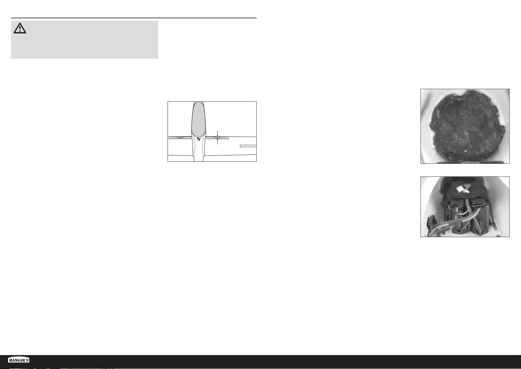
ÉQUILIBRAGE DE L’APPAREIL
ATTENTION: CETTE ÉTAPE EST OBLIGATOIRE. N’essayez
jamais de voler sans correctement équilibrer l’appareil. Un
appareil déséquilibré sera extrêmement instable et peut causer une
chute. Les dégâts consécutifs à une chute ne sont pas pris en
charge dans le cadre de la garantie.
1. Fixez les panneaux d’ailes, la verrière et les surfaces d’empennage
sur le fuselage. Veillez à bien connecter les fils de l’aileron, des
volets et des déflecteurs aux fils appropriés du récepteur. Assurezvous que les fils ne sont pas exposés à l’extérieur du fuselage
avant de serrer les boulons des ailes. Votre modèle devrait être en
position OFF (ÉTEINT), dans un état qui serait autrement prêt pour
le vol avant l’équilibrage.
2. L’emplacement du centre de gravité (CG) recommandé pour votre
maquette est de 60 à 85 mm en arrière du bord d’attaque de l’aile
à la base. Marquez l’emplacement du CG sur les ailes avec du
ruban adhésif ou un marqueur. Équilibrez votre modèle en position
debout avec vos doigts ou en équilibrant le support du modèle
avec les repères en bas de l’aile.
23/8–35/16 inches
(60–85 mm)
Ajoutez du lest au nez de l’appareil jusqu’à ce que le fuselage
soit à niveau ou légèrement le nez vers le bas sur le support
d’équilibrage.
CONSEIL: Avec du ruban adhésif, fixez un sac en plastique à
l’extérieur du nez du fuselage et ajoutez du poids, comme de la
grenaille de plomb ou Deluxe Materials Liquid Gravity (DLMBD38)
au sac jusqu’à ce que l’appareil soit équilibré.
5. Retirez les ailes, la verrière et les batteries de vol du fuselage, et
placez soigneusement le fuselage sur son nez.
6. Mélangez le lest de l’étape 5 avec de l’époxy et des micro ballons
et ajoutez-le à l’intérieur du nez du fuselage. Laissez le mélange
sécher complètement.
CONSEIL: Une alternative à l’ajout du lest directement dans le
fuselage est d’utiliser le cône du Hangar 9 RV-4 (HAN488509)
comme moule pour maintenir le mélange époxy/lest jusqu’à ce
qu’il sèche. Le cône correspond presque parfaitement à la forme
du nez ASH. Versez le mélange de lest dans le cône. Après avoir
complètement séché, le mélange peut être retiré du cône et
monté solidement dans le nez du fuselage avec de l’époxy.
3. Tenez l’appareil à la verticale au niveau des marquages réalisés sur
l’aile avec vos doigts ou avec un support d’équilibrage disponible
dans le commerce.
Si vous construisez la version sans moteur, lancée par remorque,
passez à l’étape 5.
4. Si vous construisez la version électrique, déplacez les batteries
du récepteur vers l’avant ou l’arrière dans le cockpit jusqu’à ce
que l’appareil soit à niveau ou le nez légèrement vers le bas sur le
support d’équilibrage. Lorsque le bon centre de gravité est atteint,
montez les batteries du récepteur sur le fuselage en utilisant une
bande velcro.
Passez à la section Coudes de contrôle.
CONSEIL: Si le bon point d’équilibre ne peut pas être atteint avec
les batteries du récepteur entièrement vers l’avant, ajoutez un
poids autocollant jusqu’à ce que l’appareil soit équilibré.
Retournez les batteries de vol à leur position dans le cockpit et
fixez leur emplacement.
ASH 31 6.4M ARF
59 FR
Page 60
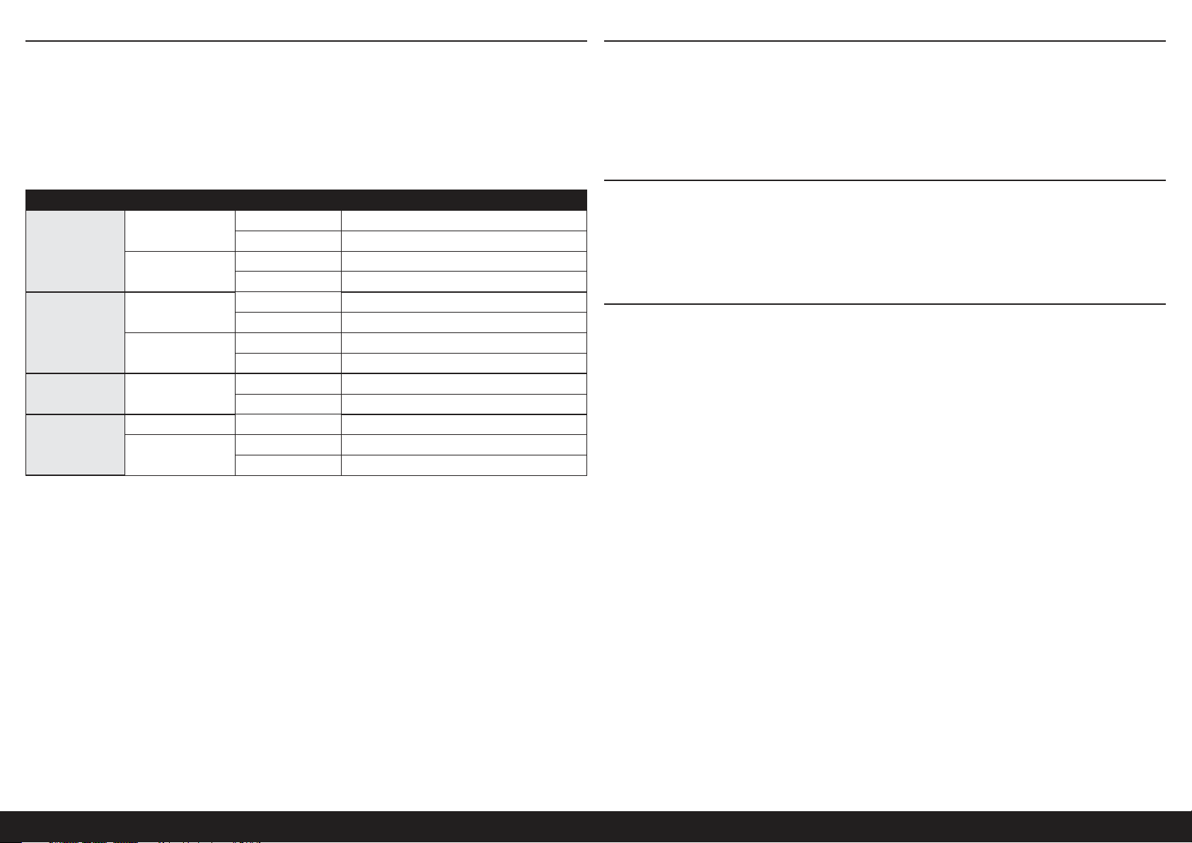
DÉBATTEMENTS
1. Mettez l’émetteur et le récepteur de votre maquette sous tension. Vérifiez le mouvement de la dérive à l’aide
de l’émetteur. Lorsque le manche se déplace vers la droite, la dérive doit également se déplacer vers la droite.
Inversez le sens du servo au niveau de l’émetteur le cas échéant.
2. Vérifiez le mouvement de profondeur à l’aide du système radio. Actionner le manche de profondeur vers le bas de
l’émetteur fait monter la profondeur de l’avion.
3. Vérifiez le mouvement des ailerons à l’aide du système radio. Actionner le manche des ailerons vers la droite fait
monter l’aileron droit et descendre l’aileron gauche.
4. Utilisez une règle pour ajuster le coude de l’élévateur, des ailerons et du gouvernail.
Surface Débattement Direction Coude
Atterrissage/Vol plané
Ailerons
Croisière/Lancement
Élevé
Profondeur
Bas
Dérive Élevé
Aileron
haute-vitesse
• En mode d’atterrissage ou de vol plané, les ailerons se déplacent indépendamment des ailerons haute-vitesse.
• En mode d’atterrissage ou de vol plané, descendez l’intégralité du bord de fuite (ailerons haute-vitesse et ailerons)
de 3-4 mm.
• En mode de croisière ou de lancement, couplez les ailerons et les ailerons haute-vitesse pour entièrement contrôler
le roulis.
• En mode de croisière ou de lancement, montez l’intégralité du bord de fuite (ailerons haute-vitesse et ailerons) de
3-4 mm.
• Utilisez une glissière pour contrôler le couple de l’aileron haute-vitesse afin de varier la quantité de course.
• Nous recommandons de baisser les ailerons haute-vitesse de 10 mm lors des décollages au ras du sol et lors du
remorquage aérien.
• Configurez l’inclinaison de la gouverne sur une quantité qui n’affecte pas le servo.
• Configurez l’inclinaison maximale de l’aileron haute-vitesse sur une quantité qui n’affecte pas le servo.
Il s’agit de directives générales obtenues à partir de nos essais en vol. Vous pouvez essayer avec d’autres
débattements qui correspondent à votre style de vol préféré.
Les réglages de la course et les sub-trims ne sont pas mentionnés et doivent être ajustés en fonction de chaque
maquette et de vos préférences. Installez toujours les palonniers de servos à la perpendiculaire des servos. N’utilisez le
sub-trim qu’en dernier recours pour centrer les servos.
Réaffectez toujours le système radio une fois que tous les coudes de contrôle sont fixés pour empêcher aux servos de
se déplacer à leurs extrémités jusqu’à ce que l’émetteur et le récepteur se branchent.
Atterrissage Bas 25–30mm
Croisière/Lancement
Haut 16mm
Bas 12mm
Haut 18–20mm
Bas 14mm
Haut 9mm
Bas 7mm
Haut 7mm
Bas 5mm
Vers la droite 35–45mm
Vers la gauche 35–45mm
Haut 18–20mm
Bas 14mm
CHECKLIST D’AVANT VOL
• Chargez l’émetteur, le récepteur et les batteries du moteur. Suivez les instructions fournies avec le chargeur. Suivez
toutes les instructions du fabricant pour vos composants électroniques.
• Contrôlez votre installation radio et que toutes les gouvernes (ailerons,profondeur, dérive et gaz) fonctionnent dans la
bonne direction et avec les bons débattements.
• Contrôlez tous les accessoires (guignols, palonniers et chapes) pour être sûr qu’ils sont en bon état.
• Avant chaque session de vol (et surtout avec un nouveau modèle), effectuez un test de portée radio. Consultez le
manuel de votre radio pour les instructions pour effectuer un test de portée.
CONTRÔLES SYSTÉMATIQUES
• Contrôlez la tension de la batterie de l’émetteur. Ne volez jamais en dessous de la tension minimale recommandée
par le fabricant. Le non-respect de cette consigne pourrait entraîner un crash.
• Contrôlez tous les accessoires (guignols, palonniers et chapes) pour être sûr qu’ils sont en bon état.
• Vérifiez que toutes les gouvernes fonctionnent de manière correcte.
• Effectuez un test de portée avant chaque journée de vol.
• Tous les fils de servo et les prises du faisceau du commutateur devraient être fixés dans le récepteur.
GARANTIE ET RÉPARATIONS
Durée de la garantie
Garantie exclusive - Horizon Hobby, LLC (Horizon) garantit que le Produit acheté (le « Produit ») sera exempt de défauts
matériels et de fabrication à sa date d’achat par l’Acheteur. La durée de garantie correspond aux dispositions légales
du pays dans lequel le produit a été acquis. La durée de garantie est de 6 mois et la durée d’obligation de garantie de
18 mois à l’expiration de la période de garantie.
Limitations de la garantie
(a) La garantie est donnée à l’acheteur initial (« Acheteur ») et n’est pas transférable. Le recours de l’acheteur consiste
en la réparation ou en l’échange dans le cadre de cette garantie. La garantie s’applique uniquement aux produits
achetés chez un revendeur Horizon agréé. Les ventes faites à des tiers ne sont pas couvertes par cette garantie. Les
revendications en garantie seront acceptées sur fourniture d’une preuve d’achat valide uniquement. Horizon se réserve
le droit de modifier les dispositions de la présente garantie sans avis préalable et révoque alors les dispositions de
garantie existantes.
(b) Horizon n’endosse aucune garantie quant à la vendabilité du produit ou aux capacités et à la forme physique de
l’utilisateur pour une utilisation donnée du produit. Il est de la seule responsabilité de l’acheteur de vérifier si le produit
correspond à ses capacités et à l’utilisation prévue.
(c) Recours de l’acheteur – Il est de la seule discrétion d’Horizon de déterminer si un produit présentant un cas de
garantie sera réparé ou échangé. Ce sont là les recours exclusifs de l’acheteur lorsqu’un défaut est constaté.
Horizon se réserve la possibilité de vérifier tous les éléments utilisés et susceptibles d’être intégrés dans le cas de
garantie. La décision de réparer ou de remplacer le produit est du seul ressort d’Horizon. La garantie exclut les défauts
esthétiques ou les défauts provoqués par des cas de force majeure, une manipulation incorrecte du produit, une
utilisation incorrecte ou commerciale de ce dernier ou encore des modifications de quelque nature qu’elles soient.
La garantie ne couvre pas les dégâts résultant d’un montage ou d’une manipulation erronés, d’accidents ou encore du
fonctionnement ainsi que des tentatives d’entretien ou de réparation non effectuées par Horizon. Les retours effectués
par le fait de l’acheteur directement à Horizon ou à l’une de ses représentations nationales requièrent une confirmation
écrite.
60FR
Page 61
Limitation des dommages
Horizon ne saurait être tenu pour responsable de dommages conséquents directs ou indirects, de pertes de revenus ou
de pertes commerciales, liés de quelque manière que ce soit au produit et ce, indépendamment du fait qu’un recours
puisse être formulé en relation avec un contrat, la garantie ou l’obligation de garantie. Par ailleurs, Horizon n’acceptera
pas de recours issus d’un cas de garantie lorsque ces recours dépassent la valeur unitaire du produit. Horizon n’exerce
aucune influence sur le montage, l’utilisation ou la maintenance du produit ou sur d’éventuelles combinaisons de
produits choisies par l’acheteur. Horizon ne prend en compte aucune garantie et n‘accepte aucun recours pour les
blessures ou les dommages pouvant en résulter. Horizon Hobby ne saurait être tenu responsable d’une utilisation ne
respectant pas les lois, les règles ou règlementations en vigueur.
En utilisant et en montant le produit, l’acheteur accepte sans restriction ni réserve toutes les dispositions relatives à la
garantie figurant dans le présent document. Si vous n’êtes pas prêt, en tant qu’acheteur, à accepter ces dispositions
en relation avec l’utilisation du produit, nous vous demandons de restituer au vendeur le produit complet, non utilisé et
dans son emballage d’origine.
Indications relatives à la sécurité
Ceci est un produit de loisirs perfectionné et non un jouet. Il doit être utilisé avec précaution et bon sens et nécessite
quelques aptitudes mécaniques ainsi que mentales. L’incapacité à utiliser le produit de manière sure et raisonnable
peut provoquer des blessures et des dégâts matériels conséquents. Ce produit n’est pas destiné à être utilisé par des
enfants sans la surveillance par un tuteur. La notice d’utilisation contient des indications relatives à la sécurité ainsi
que des indications concernant la maintenance et le fonctionnement du produit. Il est absolument indispensable de lire
et de comprendre ces indications avant la première mise en service. C’est uniquement ainsi qu’il sera possible d’éviter
une manipulation erronée et des accidents entraînant des blessures et des dégâts. Horizon Hobby ne saurait être tenu
responsable d’une utilisation ne respectant pas les lois, les règles ou règlementations en vigueur.
Questions, assistance et réparations
Votre revendeur spécialisé local et le point de vente ne peuvent effectuer une estimation d’éligibilité à l’application de
la garantie sans avoir consulté Horizon. Cela vaut également pour les réparations sous garantie. Vous voudrez bien,
dans un tel cas, contacter le revendeur qui conviendra avec Horizon d’une décision appropriée, destinée à vous aider le
plus rapidement possible.
Maintenance et réparation
Si votre produit doit faire l’objet d’une maintenance ou d’une réparation, adressez-vous soit à votre revendeur
spécialisé, soit directement à Horizon. Emballez le produit soigneusement. Veuillez noter que le carton d’emballage
d’origine ne suffit pas, en règle générale, à protéger le produit des dégâts pouvant survenir pendant le transport. Faites
appel à un service de messagerie proposant une fonction de suivi et une assurance, puisque Horizon ne prend aucune
responsabilité pour l’expédition du produit jusqu’à sa réception acceptée. Veuillez joindre une preuve d’achat, une
description détaillée des défauts ainsi qu’une liste de tous les éléments distincts envoyés. Nous avons de plus besoin
d’une adresse complète, d’un numéro de téléphone (pour demander des renseignements) et d’une adresse de courriel.
Garantie et réparations
Les demandes en garantie seront uniquement traitées en présence d’une preuve d’achat originale émanant d’un
revendeur spécialisé agréé, sur laquelle figurent le nom de l’acheteur ainsi que la date d’achat. Si le cas de garantie
est confirmé, le produit sera réparé. Cette décision relève uniquement d’Horizon Hobby.
Réparations payantes
En cas de réparation payante, nous établissons un devis que nous transmettons à votre revendeur. La réparation sera
seulement effectuée après que nous ayons reçu la confirmation du revendeur. Le prix de la réparation devra être
acquitté au revendeur. Pour les réparations payantes, nous facturons au minimum 30 minutes de travail en atelier
ainsi que les frais de réexpédition. En l’absence d’un accord pour la réparation dans un délai de 90 jours, nous nous
réservons la possibilité de détruire le produit ou de l’utiliser autrement.
ATTENTION: Nous n’effectuons de réparations payantes que pour les composants électroniques et les
moteurs. Les réparations touchant à la mécanique, en particulier celles des hélicoptères et des voitures
radiocommandées, sont extrêmement coûteuses et doivent par conséquent être effectuées par l’acheteur luimême.
10/15
COORDONNÉES DE GARANTIE ET RÉPARATIONS
Pays d’achat Horizon Hobby Telefon/Email Adresse Adresse
EU
Horizon Technischer Service
Horizon Hobby GmbH
+49 (0) 4121 2655 100
[email protected]
Hanskampring 9
D 22885 Barsbüttel, Germany
INFORMATIONS DE CONFORMITÉ POUR L’UNION EUROPÉENNE
Déclaration de conformité de l’Union européenne: Horizon Hobby, LLC déclare par la présente que ce
produit est en conformité avec les exigences essentielles et les autres dispositions de la directive CEM.
http://www.horizonhobby.com/content/support-render-compliance.
Une copie de la déclaration de conformité européenne est disponible à :
INSTRUCTIONS RELATIVES ÀL’ÉLIMINATION DES D3E POUR LES UTILISATEURS RÉSIDANT
DANS L’UNION EUROPÉENNE
Ce produit ne doit pas être éliminé avec d’autres déchets. Il est de la responsabilité de l’utilisateur
d’éliminer les équipements rebutés en les remettant àun point de collecte désigné en vue du recyclage
des déchets d’équipements électriques et électroniques. La collecte et le recyclage séparés de vos
équipements usagés au moment de leur mise au rebut aideront àpréserver les ressources naturelles
et àassurer le recyclage des déchets de manière àprotéger la santé humaine et l’environnement. Pour
plus d’informations sur les points de collecte de vos équipements usagés en vue du recyclage, veuillez
contacter votre mairie, votre service de collecte des ordures ménagères ou le magasin dans lequel vous avez acheté le
produit.
ASH 31 6.4M ARF
61 FR
Page 62
PIÈCES DE RECHANGE REQUIS POUR LA FINITION
Référence Description
EFLG630S Rentrée électrique
HAN318501 Fuselage
HAN318502 Panneau interne d’aile gauche
HAN318503 Panneau interne d’aile droite
HAN318504 Panneau externe d’aile gauche
HAN318505 Panneau externe d’aile droite
HAN318506 Ailette gauche
HAN318507 Ailette droite
HAN318508 Roues de bout d’aile
HAN318509 Stabilisateur
HAN318510 Tige d’aile en carbone
HAN318511 Tiges d’ailes externes
HAN318512 Tiges d’ailettes
HAN318513 Caches de servo (6)
HAN318514 Cockpit
HAN318515 Siège
HAN318516 Gouverne de direction
HAN318517 Pièces du train d’atterrissage
HAN318518 Portes du train d’atterrissage
HAN318519 Roue de queue
HAN318520 Charnières (4)
HAN318521 Caches de frein à air (2)
HAN318522 Bagues de retenue des ailes (2)
Toutes les versions
Nombre
requis
1 SPMAR12310T PowerSafe Tele RX 12canaux AR12310T
4 SPMSA5060 Mini-servo métallique A5060 H-T / H-S HV
2 SPMSA7050 A7050 HV Aile fine Hi Torq MG
3 SPMA3003 Rallonge de servo, 300 mm
8 SPMA3004 Rallonge de servo, 460 mm
5 SPMA3005 Rallonge de servo, 600 mm
4 SPMA3007 Rallonge de servo, 1200 mm
1 SPMA3008 Harnais résistant en Y de 150 mm
2 SPMB4000LPRX Batterie Li-Po de récepteur 7,4 V 4000 mAh
1 SPMA3054 Attaches de connexion du servo (25)
1 SPMVR5203 Régulateur à double sortie VR5203
Version sans moteur, lancée par remorque
Nombre
requis
1 SPMSA7040 Servo à rétractation A7040 HV
Version électrique
Nombre
requis
1 CSE010009700 Variateur ESC Talon 90 A 25 V BL avec BEC 20 A
1 EFLM4060B Moteur à cage tournante sans balais Power 60 de 470Kv
1 EFLP16080FA Cône, 45mm: ASW 20 4,7m
1 HAN495512 Hélice 16 x 10: ASW 20 4,7m
1 KXSB40006S40 F-Tek 4000mAh 6S 40C, EC5, LED
Référence Description
Référence Description
DLMBD38 Liquid Gravity; système de lestage
Référence Description
Référence Description
SPMA3008 Harnais résistant en Y de 150 mm
SPMAS3000 Module de stabilisation AS3000 AS3X
TAM85013 Vaporisateur de laque TS-13 transparente
TAM86024 Aérosol PS-24 Fluor Org 100ml
TAM87044 Apprêt blanc 180ml
62FR
Page 63

AVVISO
Tutte le istruzioni, le garanzie e gli altri documenti pertinenti sono soggetti a cambiamenti a totale discrezione di
Horizon Hobby, LLC. Per una documentazione aggiornata sul prodotto, visitare il sito www.horizonhobby.com e fare
clic sulla sezione Support per questo prodotto.
SIGNIFICATO DEI TERMINI PARTICOLARI
In tutta la documentazione relativa al prodotto sono utilizzati iseguenti termini per indicare vari livelli di potenziale
pericolo durante il funzionamento:
AVVERTENZA: Procedure che, se non debitamente seguite, espongono alla possibilità di danni alla proprietà fisica
opossono omportare un’elevata possibilità di provocare ferite superficiali. Ulteriori precauzioni per la sicurezza e
avvertenze.
ATTENZIONE: Procedure che, se non sono seguite correttamente, possono creare danni materiali E possibili gravi
lesioni.
AVVISO: Procedure che, se non sono seguite correttamente, possono creare danni materiali E nessuna oscarsa
possibilità di lesioni.
AVVERTENZA: Leggere TUTTO il manuale di istruzioni e prendere familiarità con le caratteristiche del prodotto, prima
di farlo funzionare. Un utilizzo scorretto del prodotto può causare danni al prodotto stesso, alle persone oalle cose,
provocando gravi lesioni.
Questo è un prodotto di hobbistica sofisticato e NON un giocattolo. È necessario farlo funzionare con cautela e
responsabilità e avere conoscenze basilari di meccanica. Se questo prodotto non è utilizzato in maniera sicura e
responsabile potrebbero verificarsi lesioni odanni al prodotto stesso oad altre proprietà. Non è un prodotto adatto
aessere utilizzato dai bambini senza la diretta supervisione di un adulto. Non usare componenti non compatibili
o alterare il prodotto in nessuna maniera al di fuori delle istruzioni fornite da Horizon Hobby, LLC. Questo manuale
contiene le istruzioni per un funzionamento e una manutenzione sicuri. È fondamentale leggere e seguire tutte le
istruzioni e le avvertenze del manuale prima di montare, configurare ofar funzionare il Prodotto, al fine di utilizzarlo
correttamente e di evitare danni olesioni gravi.
RACCOMANDAZIONI PER OPERARE IN SICUREZZA
• Controllare attentamente il modello prima di ogni volo per accertarsi che sia idoneo.
• Essere consapevoli che un altro utente della frequenza in uso, potrebbe procurare delle interferenze.
• Essere sempre cortesi e rispettosi nei confronti degli altri utilizzatori dell’area in cui ci si trova.
• Scegliere un’area libera da ostacoli e abbastanza ampia da permettere lo svolgimento del volo in sicurezza.
• Prima del volo verificare che l’area sia libera da amici e spettatori.
• Stare attenti alle altre attività che si svolgono in vicinanza della vostra traiettoria di volo, per evitare possibili conflitti.
• Pianificare attentamente il volo prima di lanciare il modello.
• Rispettare sempre scrupolosamente le regole stabilite dall’associazione locale.
PRIMA DI INIZIARE IL MONTAGGIO
• Togliere tutti i pezzi dalla scatola.
• Verificare che la fusoliera, l’ala e i piani di coda non siano danneggiati.
• Se si trovano parti danneggiate, contattare il negozio da cui è stato acquistato.
• Caricare il trasmettitore e la batteria di volo.
• Centrare stick e trim sul trasmettitore.
• Con una radio computerizzata creare una nuova memoria per questo modello.
• Facendo riferimento alle istruzioni del radiocomando, connettere (bind) trasmettitore e ricevitore.
AVVISO: una volta impostate tutte le corse dei comandi, effettuare nuovamente la connessione del radiocomando.
Ciò impedirà che i servocomandi si spostino verso i propri fine corsa prima del collegamento della trasmittente
con il ricevitore. Ciò inoltre farà in modo che le impostazioni di inversione dei servocomandi siano salvate nel
radiocomando.
MINIMO 14 ANNI. NON È UN GIOCATTOLO.
AVVERTIMENTI E PRECAUZIONI PER LA SICUREZZA
Prima dell’uso leggere attentamente tutte le istruzioni e le precauzioni per la sicurezza. In caso contrario si potrebbero
procurare incendi, danni o ferite.
Componenti
Usare solo componenti compatibili. Se ci fossero dubbi riguardo alla compatibilità, è opportuno far riferimento alle
istruzioni relative al prodotto o ai componenti oppure rivolgersi al reparto Horizon Hobby di competenza.
Volo
Per sicurezza volare solo in aree molto ampie. Meglio se in campi volo autorizzati per modellismo. Consultare le
ordinanze locali prima di scegliere luogo dove volare.
Elica
Tenere gli oggetti liberi (vestiti, penne, cacciaviti, ecc.) lontano dall’elica, prima che vi restino impigliati. Bisogna fare
attenzione anche con le mani perché c’è il rischio di ferirsi anche gravemente.
Batterie
Quando si maneggiano o si utilizzano le batterie, bisogna attenersi alle istruzioni del costruttore; il rischio è di procurare
incendi, specialmente con le batterie LiPo, con danni e ferite serie.
Piccole parti
Questo kit comprende delle parti di piccole dimensioni e non lo si può lasciare incustodito se c’è la presenza di bambini
che li possono inghiottire e rimanere soffocati o intossicati.
ASH 31 6.4M ARF
63 IT
Page 64
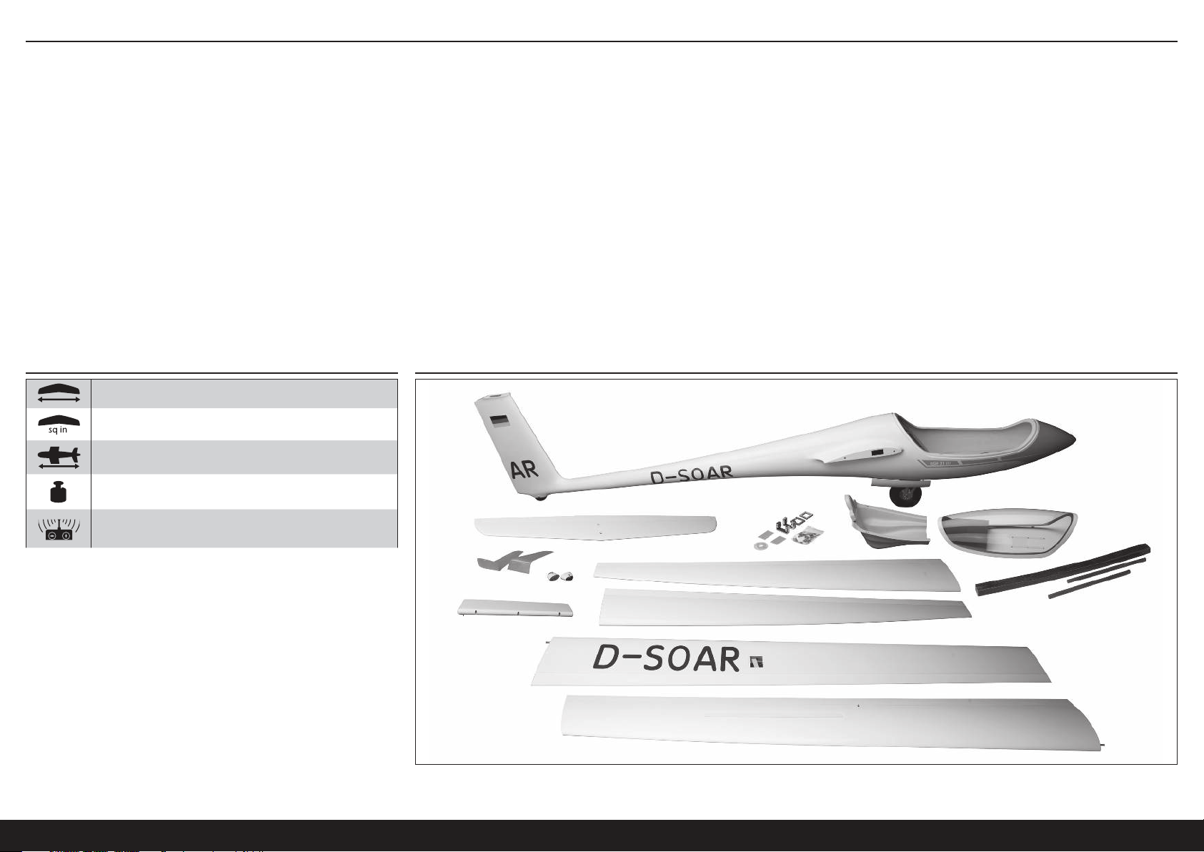
SOMMARIO
Avviso ....................................................................................................................................................................63
Significato dei termini particolari ............................................................................................................................63
Avvertimenti E Precauzioni Per La Sicurezza ..........................................................................................................63
Consignes de sécurité concernant l’utilisation ........................................................................................................63
Avant de commencer l’assemblage .......................................................................................................................63
Specifiche ..............................................................................................................................................................64
Schema Dei Componenti Grandi .............................................................................................................................64
Componenti necessari per l’assemblaggio .............................................................................................................65
Articoli Opzionali ....................................................................................................................................................65
Articoli aggiuntivi necessari ...................................................................................................................................65
Utensili necessari ...................................................................................................................................................65
Precauzioni per l’assemblaggio ..............................................................................................................................66
Trasporto e immagazzinaggio ................................................................................................................................66
Conservazione della colorazione fluorescente ........................................................................................................66
Pannelli esterni delle ali .........................................................................................................................................66
Pannelli interni delle ali ..........................................................................................................................................68
Installazione dell’aletta di estremità .......................................................................................................................71
Installazione del timone .........................................................................................................................................71
Installazione dell’elevatore .....................................................................................................................................73
Installazione del meccanismo di sgancio del traino ................................................................................................74
Installazione del radiocomando ..............................................................................................................................74
Installazione della cabina di pilotaggio ...................................................................................................................75
Installazione opzionale dei sistema di alimentazione elettrica .................................................................................75
Assemblaggio finale ...............................................................................................................................................78
Bilanciamento dell’aeromodello .............................................................................................................................79
Corse dei comandi .................................................................................................................................................80
Lista Dei Controlli Prima Del Volo ...........................................................................................................................80
Controlli Di Volo Giornalieri .....................................................................................................................................80
Garanzia ................................................................................................................................................................80
Contatti Per La Garanzia E L’Assistenza ..................................................................................................................81
Informazioni sulla conformità per l’Unione Europea ................................................................................................81
Istruzioni per lo smaltimento di RAEE da parte di utenti dell’Unione Europea ..........................................................81
Pezzi Di Ricambio ..................................................................................................................................................82
Componenti necessari per l’assemblaggio .............................................................................................................82
Articoli Opzionali ....................................................................................................................................................82
Articoli aggiuntivi necessari ...................................................................................................................................82
SPECIFICHE SCHEMA DEI COMPONENTI GRANDI
6,4 m (252 in)
123,87 dm2 (1920 sq in)
2,2 m (88 in)
11,8 kg (26 lbs)
6 canali (o più) con 7 servocomandi
64IT
Page 65
COMPONENTI NECESSARI PER L’ASSEMBLAGGIO
Tutte le versioni
N. richiesto Componente n. Descrizione
1 SPMAR12310T PowerSafe Tele RX 12 canali AR12310T
4 SPMSA5060 Mini servocomando alta tensione metallico H-T / H-S A5060
2 SPMSA7050 Servocomando alta tensione MG elevata coppia ala sottile A7050
3 SPMA3003 Estensione servo 300 mm
8 SPMA3004 Estensione servo 460 mm
5 SPMA3005 Estensione servo 600 mm
4 SPMA3007 Estensione servo 1200 mm
1 SPMA3008 Prolunga a Y Heavy Duty, 150 mm
2 SPMB4000LPRX Batteria per ricevitore da 7,4 V Li-Po, 4.000 mAh
1 SPMA3054 Morsetti servocomando (25)
1 SPMVR5203 Regolatore duplice uscita VR5203
Versione senza alimentazione, trainata-lanciata
N. richiesto Componente n. Descrizione
1 SPMSA7040 Servocomando alta tensione per elementi retrattili A7040
DLMBD38 Prodotto per aggiunta peso “Liquid Gravity”
Versione con alimentazione elettrica
N. richiesto Componente n. Descrizione
1 CSE010009700 ESC BL Talon 90-Amp 25 V con BEC 20amp
1 EFLM4060B Motore brushless a cassa rotante Power 60, 470Kv
1 EFLP16080FA Ogiva, 45 mm: ASW 20 4,7 m
1 HAN495512 Elica 16 x 10: ASW 20 4,7 m
1 KXSB40006S40 Batteria F-Tek 4000mAh 6S 40C, EC5, con LED
ARTICOLI OPZIONALI
Componente n. Descrizione
SPMA3008 Prolunga a Y Heavy Duty, 150 mm
SPMAS3000 Modulo di stabilizzazione AS3000 AS3X
TAM85013 Smalto spray trasparente TS-13
TAM86024 Bomboletta spray arancio fluorescente PS-24 100 ml
TAM87044 Primer bianco 180 ml
UTENSILI NECESSARI
Descrizione
Supporto per bilanciamento
Chiavi: 17mm
Morsetti
Nastro trasparente
Pinza crimpatrice
Colla CA (adesivo cianoacrilato) fine e media
Trapano con punte di varie dimensioni
Colla epossidica
Spazzole epoxy
Pennarello
Alcol isopropilico
Pinzetta
Hex drivers, metric, various sizes
Taglierino: #11 lama
Lunga asta in plastica
Nastro per mascheratura a bassa adesione
Carta vetrata media
Righello metrico
Riempitivo in microsfere
Contenitori e stick per mixer colla
Asciugamani di carta
Matita
Cacciavite a croce: #1, #2
Trapano manuale
Pinze
Trapano con disco da taglio, smerigliatrice, taglierino al carburo, mola
Saldatore a punta e pasta saldante
Filo
ARTICOLI AGGIUNTIVI NECESSARI
Trasmittente 6 canali o più
Caricabatterie LiPo
ASH 31 6.4M ARF
Descrizione
65 IT
Page 66

PRECAUZIONI PER L’ASSEMBLAGGIO
Prima di iniziare l’assemblaggio, preparare il piano di lavoro. Il piano
deve essere morbido e privo di oggetti taglienti. Si consiglia di posare i
componenti della cellula dell’aeromodello su un asciugamano morbido
o su un tappetino da lavoro per evitare di graffiare o intaccare la
superficie dell’aeromodello.
TRASPORTO E IMMAGAZZINAGGIO
In occasione del trasporto e immagazzinaggio del proprio modello si
dovrà disporre di uno spazio minimo in lunghezza pari a 2 metri (80
pollici) e in altezza pari a 46 cm (18 pollici) per alloggiare la dimensione
della fusoliera. Si consiglia inoltre di utilizzare borse per le ali e per lo
stabilizzatore per agevolare la protezione di queste superfici durante
il trasporto e l’immagazzinaggio. Le squadrette di controllo e le aste
di collegamento possono provocare danni alle altre superfici anche se
posizionate nelle borse di stoccaggio. Per impedire danni, trasportare
e conservare sempre le ali e lo stabilizzatore in modo che le aste di
collegamento non entrino in contatto con altri pannelli.
CONSERVAZIONE DELLA COLORAZIONE FLUORESCENTE
La colorazione fluorescente utilizzata sul vostro modello può sbiadire
con il tempo a causa dell’esposizione alla luce diretta del sole. Per
aumentare la durata della colorazione fluorescente sull’aeromodello,
limitare l’esposizione alla luce diretta del sole quando esso non è in
volo.
Se si rendono necessarie riparazioni o nel caso si decida di dipingere
componenti opzionali per abbinarli al colore della fusoliera, la vernice
spray Tamiya PS-24, colore arancio fluorescente, rappresenta la tinta
che più si avvicina alla colorazione utilizzata sul modello. Per risultati
migliori, la vernice PS-24 deve essere spruzzata sopra il primer bianco
fine Tamiya (TAM87044) e rivestita con vernice trasparente Tamiya
TS-13.
PANNELLI ESTERNI DELLE ALI
1. Rimuovere il nastro di imballaggio, pulire e levigare la superficie
dell’ala.
2. Tagliare un foro di accesso nell’estremità della radice del pannello
esterno dell’ala utilizzando un trapano.
CONSIGLIO: effettuare un foro con una larghezza esattamente
sufficiente al passaggio del connettore del servocomando. Se
il foro è troppo grande, la prolunga, quando scollegata, cadrà
all’indietro nel pannello dell’ala.
3. Individuare i supporti corti dei servocomandi. Effettuare dei fori
pilota per le viti dei supporti dei servocomandi.
4. Prestando attenzione, rendere ruvida la superficie di montaggio
del servocomando dell’ala per il supporto del servocomando
utilizzando un trapano oppure carta abrasiva, grana 80. Sfregare
solo leggermente la superficie interna del pannello dell’ala per
fornire alla colla epossidica qualcosa su cui fare presa. NON
carteggiare completamente la superficie del pannello dell’ala.
Pulire attentamente la superficie di montaggio con alcool
denaturato o alcool isopropilico al 91%.
5. Tagliare 3 bracci da una squadretta del servocomando a 4 bracci.
6. Provare il montaggio del servocomando con il braccio
del servo installato. Allargare l’apertura nel supporto
della misura necessaria a consentire l’alloggiamento
completo del servocomando nel supporto.
Provare il montaggio delle viti dei supporti dei
servocomandi anche per essere sicuri che non
sporgano attraverso il supporto e danneggino la
superficie dell’ala. Se le viti sporgono, tagliarle in modo
che rimangano sotto la superficie del supporto.
66IT
Page 67
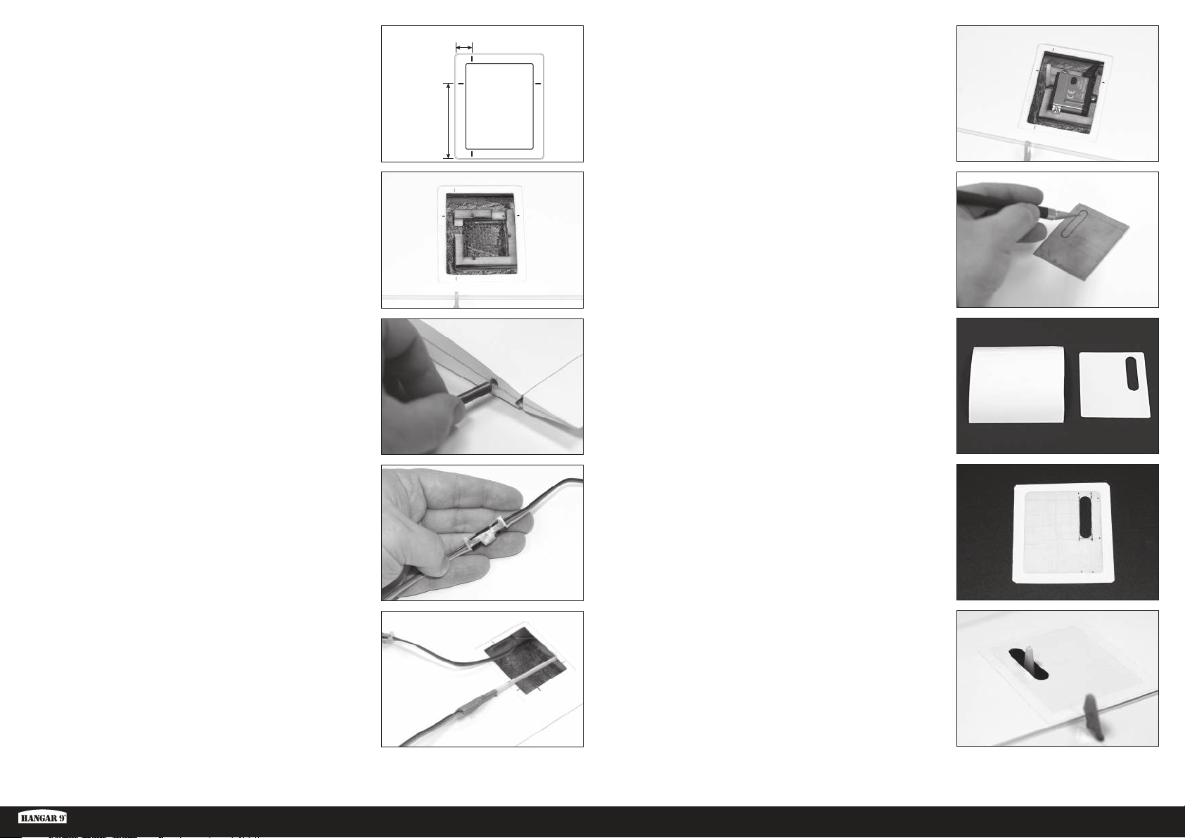
7. Misurare e contrassegnare il pannello dell’ala a livello dello
sportello del servocomando: 10 mm dal bordo esterno rialzato del
portello e 45 mm dal bordo posteriore rialzato.
Durante il montaggio del telaio nell’ala, il bordo del telaio si allinea
con i segni anteriori e posteriori e l’uscita del servo si allinea con il
segno a 45 mm.
45 mm
10 mm
12. Installare il braccio del servocomando. Installare il servocomando
nel supporto utilizzando viti corte per il servocomando (2 x 8 mm).
8. Utilizzando colla epossidica (DLMAD64), installare il supporto del
servocomando sul pannello dell’ala. Assicurarsi che il braccio del
servocomando si allinei con la squadretta della superficie. L’intaglio
per il gioco del braccio deve essere rivolto verso l’estremità alare
e l’intaglio per il cavo del servocomando deve essere rivolto
in avanti. Pulire con un panno di carta e alcool, dalla zona di
montaggio del servocomando, eventuali residui di colla epossidica
che potrebbero interferire con il montaggio del servocomando nel
supporto. Lasciare asciugare completamente la colla epossidica.
9. Servendosi di colla epossidica, installare perni anti-rotazione
nell’estremità della radice del pannello. Non spingere il perno oltre
la metà della lunghezza del perno stesso. Rimuovere l’eventuale
colla epossidica in eccesso usando un panno di carta e alcool.
10. Collegare una prolunga da 300 mm (12 pollici) del cavo del
servocomando al servocomando dell’alettone. Fissare la prolunga
con una clip per connettori dei servocomandi (SPMA3054) oppure
con guaina termorestringente.
11. Utilizzare un filo con un peso fissato allo stesso oppure una lunga
asta in plastica per infilare la prolunga del cavo assemblata
attraverso il pannello dell’ala e farla passare al fuori del foro di
accesso tagliato in precedenza.
CONSIGLIO: far passare il filo o l’asta di plastica attraverso il foro
di accesso verso lo sportello del servocomando e fissare il cavo del
servocomando all’estremità. Tirare indietro l’estremità del cavo del
servocomando attraverso il foro di accesso.
13. Utilizzando un trapano oppure un taglierino, misurare attentamente
e tagliare il foro nello sportello per il braccio del servocomando.
Provare spesso il montaggio dello sportello per garantire un gioco
adeguato del braccio del servocomando attraverso l’intera corsa
del servocomando. Arrotondare gli angoli esterni dello sportello
per un montaggio completo nella zona di montaggio incassata del
pannello dell’ala.
14. Tagliare un pezzo di pellicola adesiva bianca UltraTrim
(HANU80000) circa 3 cm più grande delle dimensioni dello
sportello del servocomando.
15. Staccare e incollare la pellicola adesiva al lato rifinito dello
sportello del servocomando.
CONSIGLIO: iniziare al centro dello sportello e premere con
attenzione eliminando eventuali bolle d’aria e pieghe dalla pellicola
mentre si procede verso i bordi.
Tagliare e rimuovere il foro per il braccio del servocomando.
Ritagliare la pellicola in modo che copra circa 10 mm oltre il bordo
dello sportello. Quindi allentare gli angoli nel modo indicato per
contribuire a evitare che gli angoli si sollevino dopo l’utilizzo.
16. Installare con attenzione lo sportello del servocomando sul
pannello dell’ala, posizionando lo sportello nel vano del pannello
dell’ala e premendo la pellicola sul pannello dell’ala attorno al
perimetro dello sportello. Operare verso l’esterno partendo dallo
sportello per rimuovere eventuali bolle d’aria o pieghe.
ASH 31 6.4M ARF
67 IT
Page 68
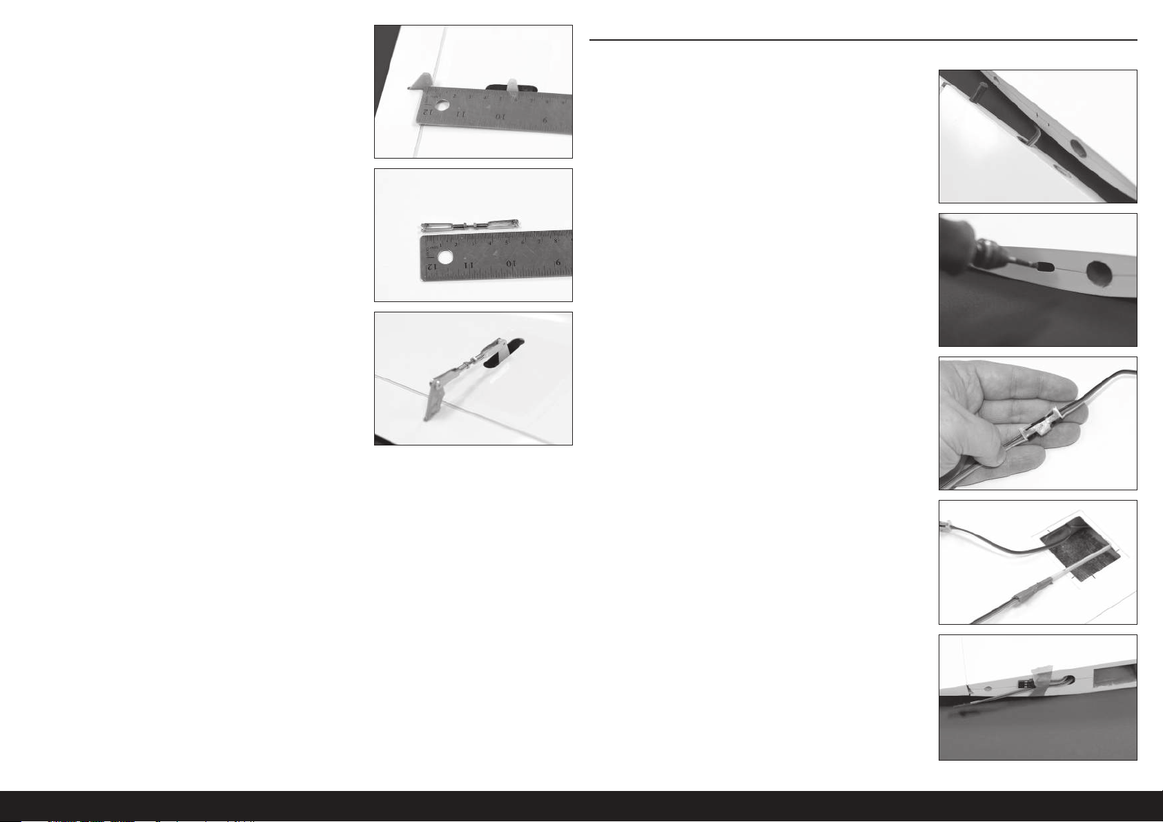
17. Con l’alettone mantenuto al centro, effettuare una misurazione tra i
fori del braccio del servocomando e la squadretta.
18. Impostare le lunghezza dell’asta di comando dell’alettone sulla
misurazione indicata sopra, facendo ruotare la forcella verso
l’interno o verso l’esterno a entrambe le estremità dell’asta di
comando. Una volta raggiunta la lunghezza corretta, applicare
il composto frenafiletti e serrare i dadi sulla forcella. Cercare di
centrare l’asta filettata tra le due forcelle.
CONSIGLIO: se lo si desidera, l’asta filettata in eccesso può essere
tagliata. Lasciare una parte dell’asta sufficiente tale che almeno 3
filetti siano visibili all’interno della forcella, come indicato.
19. Installare l’asta di comando sul servocomando e sulle squadrette
della superficie di controllo. Assicurarsi che la superficie di
controllo sia centrata quando il servocomando è in posizione folle.
PANNELLI INTERNI DELLE ALI
1. Rimuovere il nastro di imballaggio, pulire e levigare la superficie
dell’ala.
2. Posare il pannello esterno dell’ala rifinito vicino al pannello interno
dell’ala come indicato. Contrassegnare la posizione del foro di
accesso dell’ala esterna sul pannello interno dell’ala.
3. Tagliare fori di accesso sia nelle estremità esterne, sia in quelle
della radice, del pannello interno dell’ala. I fori devono essere di
grandezza esattamente sufficiente al passaggio dei connettori dei
servocomando, per impedire che le estremità cadano all’indietro
all’interno dell’ala.
4. Collegare insieme una prolunga da 1200 mm (48 pollici) e una da
600 mm (24 pollici) per creare una prolunga interna dell’alettone.
Fissare con una clip o con guaina termorestringente.
20. Ripetere i passaggi 1-19 per il pannello esterno dell’altra ala.
5. Inserire una lunga asta in plastica, o un filo con un peso fissato
allo stesso, attraverso il foro di accesso tagliato, sia all’estremità
del pannello sia all’esterno dello sportello del servocomando
dei flap. Fissare all’asta di comando un’estremità della prolunga
assemblata del servocomando dell’alettone. Tirare l’estremità della
prolunga attraverso il pannello dell’ala e fuori dal foro di accesso.
Fissare con nastro l’estremità della prolunga all’estremità del
pannello dell’ala.
Ripetere la procedura dall’altra estremità del pannello per tirare
l’estremità opposta della prolunga del servocomando dell’alettone
attraverso il foro di accesso nell’altra estremità del pannello
dell’ala.
68IT
Page 69
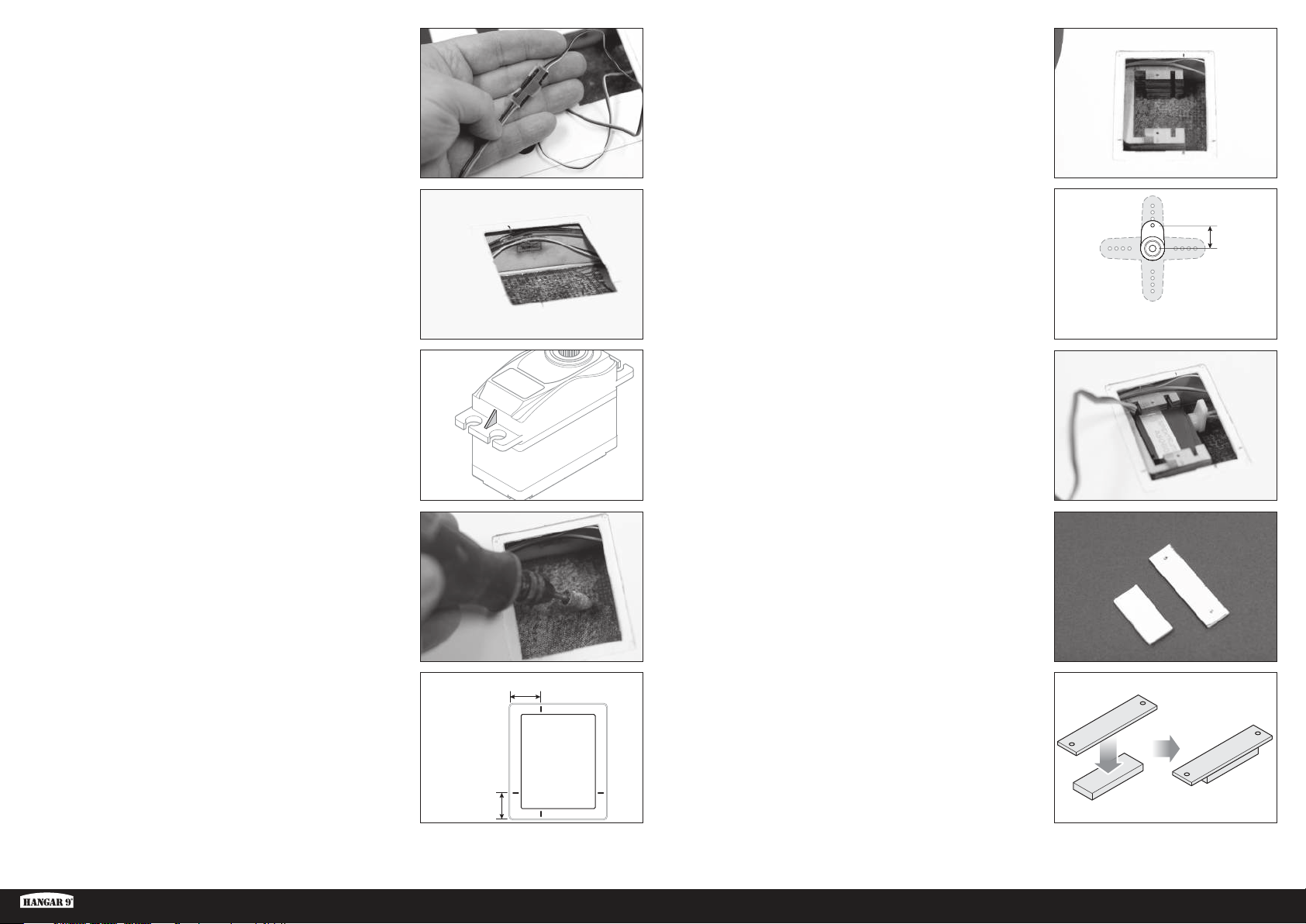
10mm
6. Collegare una prolunga del servocomando da 460 mm (18
pollici) al cavo dello spoiler e fissarlo con una clip o con guaina
termorestringente. Infilare la prolunga attraverso l’estremità interna
del pannello dell’ala come in precedenza.
7. Usando colla calda o adesivo a contatto, come il Foam2Foam
della Deluxe Systems (DLMAD34), fissare i cavi dell’alettone e dello
spoiler al longherone di fronte allo sportello del servocomando. Tale
operazione servirà a impedire che i cavi si spostino e interferiscano
con il braccio e l’asta di comando del servocomando dei flap.
11. Installare il supporto del servocomando dei flap utilizzando
colla epossidica. Allineare il supporto con i segni effettuati nel
passaggio precedente. Rimuovere eventuale colla epossidica che
possa infilarsi nelle fessure delle alette di montaggio o nella base
interna del supporto e che possa interferire con il servocomando.
Assicurarsi che il supporto aderisca al longherone dell’ala ed anche
alla superficie e che il braccio del servocomando si allinei con la
squadretta dei flap. Lasciare asciugare completamente la colla
epossidica.
12. Tagliare il braccio del servocomando dei flap fino a raggiungere
una lunghezza.
8. Ritagliare con attenzione i rinforzi dalle alette di montaggio del
servocomando. Provare il montaggio del servocomando nel
supporto del servocomando. Il servocomando deve adattarsi in
modo molto aderente al supporto.
9. Prestando attenzione, sfregare la superficie di montaggio del
servocomando dei flap dell’ala per il supporto servocomando
delle ali utilizzando un trapano oppure carta abrasiva, grana
80. Sfregare solo leggermente la superficie interna del pannello
dell’ala per fornire alla colla epossidica qualcosa su cui fare
presa. NON carteggiare completamente la superficie del pannello
dell’ala. Pulire attentamente la superficie di montaggio con alcool
denaturato o alcool isopropilico.
10. Misurare e contrassegnare l’apertura dello sportello del
servocomando dei flap, 12 mm dalla linea posteriore del vano e 17
mm dalla linea esterna del vano, come indicato nella figura.
13. Centrare il servocomando e installare la squadretta angolata
leggermente verso il bordo di fuga dell’ala.
14. Far scorrere il servocomando all’interno del supporto nel modo
indicato.
15. Utilizzando la dima di acetato in dotazione, creare una piastra di
bloccaggio del servocomando utilizzando una lamina da 3 mm (1/8
pollice) e 1,5 mm (1/16 di pollice).
17 mm
ASH 31 6.4M ARF
12 mm
69 IT
Page 70

79mm
16. Fissare il servocomando nel supporto con la piastra di bloccaggio
del servocomando e due viti. Assicurarsi che le teste delle viti si
collochino al di sotto della superficie di montaggio dello sportello
del servocomando e che le viti non danneggino la superficie
esterna del pannello dell’ala.
17. Collegare una prolunga del servocomando da 460 mm (24 pollici)
al cavo del servocomando e fissarla con una clip o con guaina
termorestringente. Infilare la prolunga attraverso l’estremità
della radice dell’ala del pannello dell’ala, utilizzando una lunga
asta in plastica o un filo con un peso fissato allo stesso, come in
precedenza.
20. Installare tramite nastro lo sportello del servocomando sull’ala nel
modo utilizzato sul pannello esterno dell’ala.
18. Tagliare le aste di comando a una lunghezza di 79 mm.
19. Installare l’asta di comando sulla squadretta dei flap e sul braccio
del servocomando. Spostare verso il basso il flap e inserire
un’estremità dell’asta di comando attraverso il foro nel bordo di
fuga dell’ala e collegarla al braccio del servocomando. Collegare
l’altra estremità dell’asta di comando alla squadretta dei flap.
21. Servendosi di colla epossidica, installare perni anti-rotazione
nell’estremità della radice del pannello. Rimuovere l’eventuale
colla epossidica in eccesso usando un panno di carta e alcool.
22. Ritagliare e fissare, utilizzando adesivo a contatto, il coperchio di
uscita dell’asta di comando dei flap sulla parte superiore dell’ala.
23. Ripetere i passaggi 1-22 per il pannello interno dell’altra ala.
70IT
Page 71
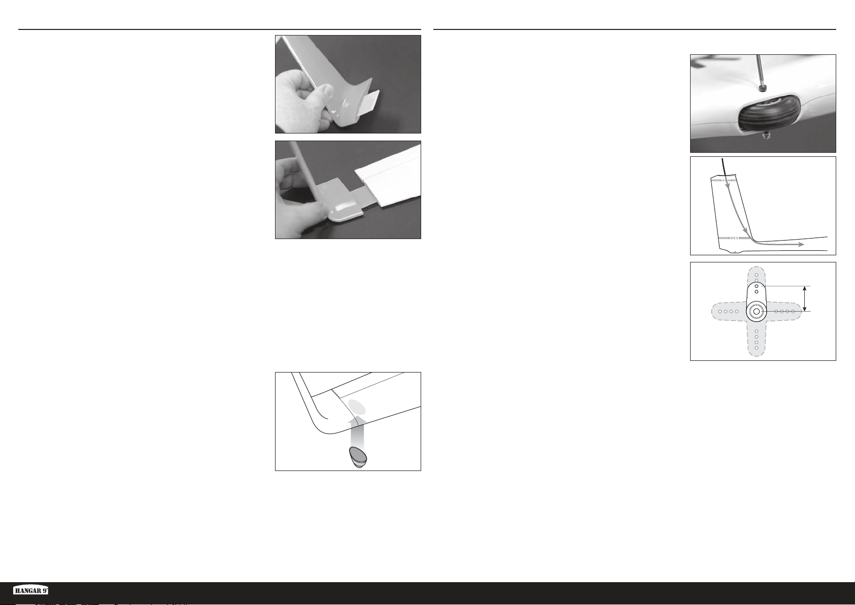
13mm
INSTALLAZIONE DELL’ALETTA DI ESTREMITÀ
1. Far scorrere la lamella dell’aletta di estremità dentro la fessura
dell’aletta di estremità.
2. Far scorrere l’assieme nella fessura nella punta del pannello
esterno dell’ala.
INSTALLAZIONE DEL TIMONE
1. Pulire e levigare la fusoliera.
2. Rimuovere il ruotino di coda utilizzando una chiave esagonale da
2,5 mm.
3. Inserire un filo con un peso fissato allo stesso o una lunga asta
flessibile attraverso l’apertura del servocomando dell’elevatore,
attraverso l’aletta verticale, attraverso il piccolo foro davanti
all’apertura del servocomando del timone e verso l’alto attraverso
la coda della fusoliera. Ciò sarà utilizzato in seguito per tirare le
prolunghe del servocomando del timone e dell’elevatore attraverso
la fusoliera.
3. Ritagliare, se necessario, la lamella dell’aletta di estremità a una
lunghezza tale che l’aletta di estremità aderisca perfettamente al
pannello dell’ala. Non deve esserci gioco tra il pannello e l’aletta di
estremità.
4. La lamella deve aderire perfettamente sia all’aletta di estremità
che al pannello esterno dell’ala. Per maggiore sicurezza, l’aletta di
estremità deve essere fissata in posizione tramite nastro.
5. Utilizzando colla epossidica, fissare una ruota per l’estremità
alare alla parte inferiore del pannello esterno dell’ala, vicino
all’estremità.
CONSIGLIO: utilizzare carta abrasiva a grana fine o una spugnetta
abrasiva per sfregare leggermente la superficie del pannello
dell’ala dove la ruota sarà fissata, per fornire alla colla epossidica
qualcosa sui cui fare presa.
Ripetere i passaggi 1-5 per l’altra estremità alare.
4. Ritagliare un braccio del servocomando di 13 mm.
5. Centrare il servocomando del timone e installare il braccio del
servocomando.
6. È necessaria una prolunga da 1500 mm (60 pollici) del
servocomando per il servocomando del timone. Collegare una
prolunga da 1200 mm (48 pollici) e una da 300 mm (12 pollici) al
servocomando del timone. Fissare tutti i collegamenti con clip per le
prolunghe dei servocomandi oppure con guaina termorestringente.
ASH 31 6.4M ARF
71 IT
Page 72
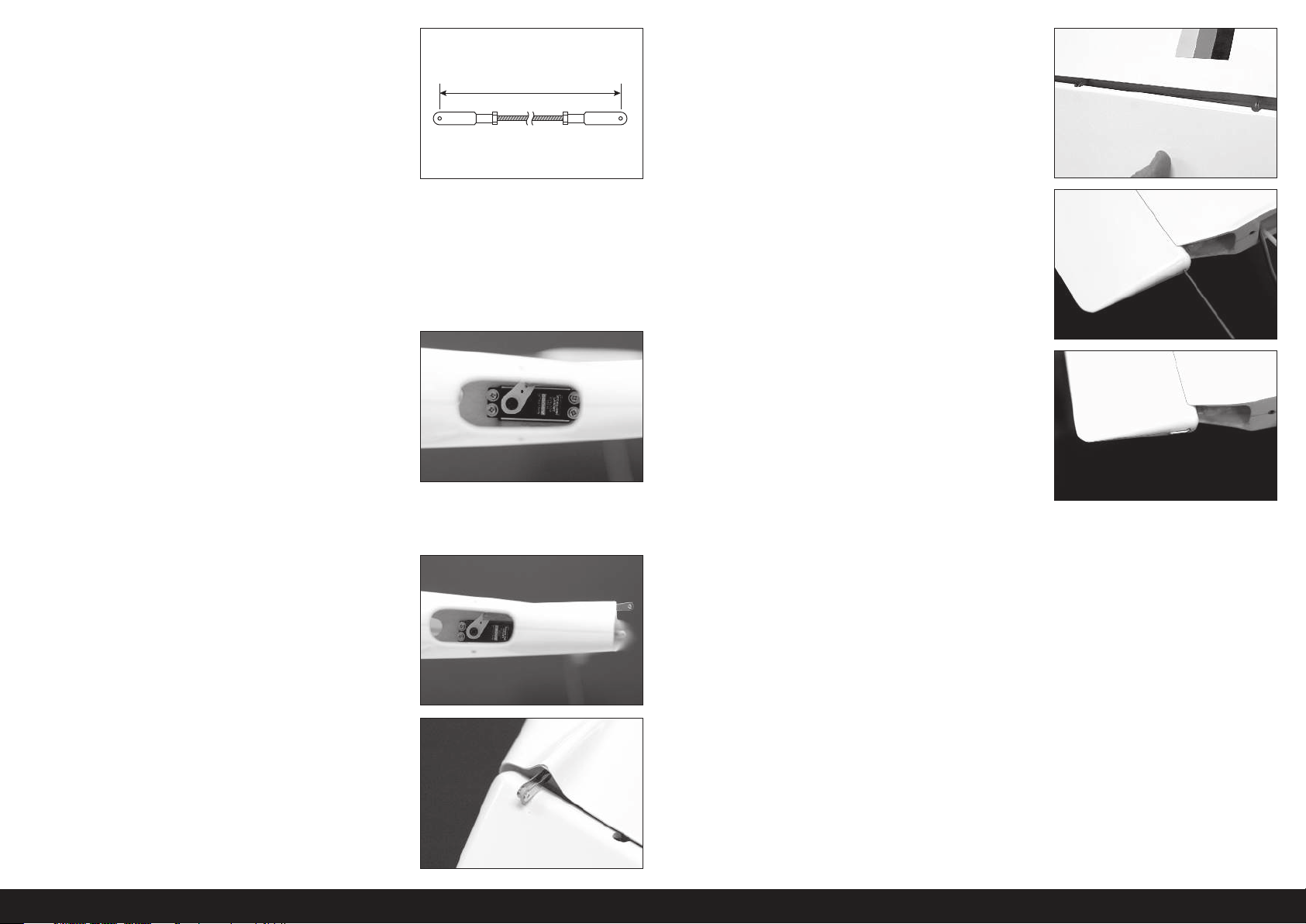
95mm
7. Ritagliare l’asta di comando del timone in modo che la lunghezza
rifinita tra i perni della forcella sia di 95 mm. Fissare un’estremità
dell’asta di comando al braccio del servocomando del timone.
12. Spingere il timone sopra i punti di articolazione nell’aletta.
8. Con la fusoliera capovolta in un supporto, inserire la prolunga del
servocomando attraverso l’apertura del servocomando del timone
e fuori dall’apertura del servocomando dell’elevatore fino alla parte
superiore dell’aletta. Questa prolunga sarà tirata successivamente
attraverso la fusoliera con la prolunga del servocomando
dell’elevatore.
9. Installare il servocomando del timone attraverso l’apertura
del ruotino di coda e dentro il supporto del servocomando. Il
servocomando è installato con l’albero di uscita verso la parte
anteriore dell’aeromodello e il braccio del servocomando verso
il lato sinistro della fusoliera. Inserire l’estremità aperta dell’asta
di comando attraverso l’apertura sagomata nella coda mentre si
monta il servocomando in posizione. Mantenere una certa tensione
sul cavo del servocomando per fare in modo che il cavo non
rimanga pizzicato nell’apertura.
CONSIGLIO: per installare le viti del servocomando, utilizzare un
cacciavite magnetico o fissare un piccolo magnete a un normale
cacciavite.
10. Ruotare la squadretta del servocomando in modo che l’asta di
comando si estenda al di fuori della parte posteriore dell’aletta.
13. Inserire con attenzione il perno della cerniera del timone attraverso
il foro nella parte superiore del timone e infilarlo completamente
attraverso ciascuno dei punti di articolazione fino alla sua
fuoriuscita attraverso la parte inferiore del timone.
CONSIGLIO: il perno della cerniera presenta un fissaggio a
frizione molto stretto. Per fare in modo che il perno si inserisca
completamente, può essere necessario spingere leggermente o
effettuare una leggera trazione sul timone mentre il perno è inserito.
Non forzare il perno. Se si avverte resistenza, spostare leggermente
il timone e continuare a inserire il perno.
14. Una volta inserito completamente, se si ritiene opportuno oppure
nel caso il perno della cerniera sia eccessivamente allentato, il
perno della cerniera può essere fissato con nastro sulla parte
superiore del timone.
11. Fissare la squadretta del timone all’asta di comando.
72IT
Page 73
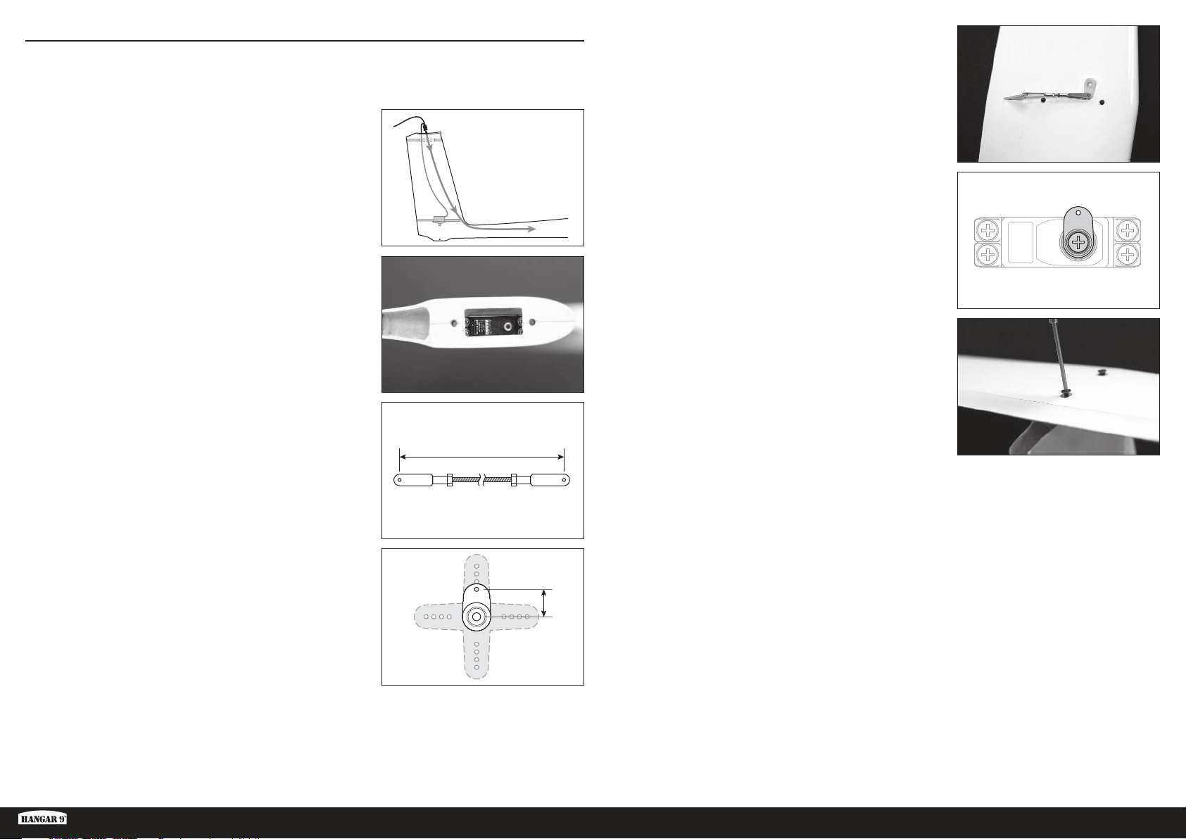
53mm
10mm
INSTALLAZIONE DELL’ELEVATORE
1. È necessaria una prolunga da 1800 mm (72 pollici) del servocomando per il servocomando dell’elevatore.
Collegare insieme una prolunga da 1200 mm (48 pollici) e una da 600 mm (24 pollici) e collegarle al
servocomando dell’elevatore. Fissare tutti i collegamenti con clip oppure con guaina termorestringente.
2. Fissare con nastro le estremità delle prolunghe del servocomando
del timone e dell’elevatore all’estremità dell’asta flessibile o del
filo che era stato inserito in precedenza nella fusoliera. Facendo
attenzione, tirare le prolunghe del servocomando attraverso la
fusoliera e fino alla cabina di pilotaggio.
3. Montare il servocomando dell’elevatore in posizione, con l’albero di
uscita rivolto verso la parte anteriore dell’aeromodello. Assicurarsi
che il cavo del servocomando non rimanga pizzicato.
4. Ritagliare l’asta di comando dell’elevatore in modo che la
lunghezza rifinita tra i perni della forcella sia di 53 mm. Le forcelle
devono essere ad angolo retto l’una rispetto all’altra.
6. Fissare un’estremità dell’asta di comando al braccio del
servocomando dell’elevatore e l’altra estremità alla squadretta
dell’elevatore.
7. Inserire l’asta di comando dell’elevatore a cui è fissato il braccio del
servocomando attraverso la parte superiore dell’aletta. Centrare il
servocomando dell’elevatore. Fissare ad angolo retto la squadretta
del servocomando all’albero di uscita del servocomando come
mostrato nella figura.
8. Fissare lo stabilizzatore orizzontale all’aletta utilizzando due viti a
testa piana M4 X 20mm.
5. Ritagliare un braccio del servocomando dell’elevatore di 10 mm.
ASH 31 6.4M ARF
73 IT
Page 74
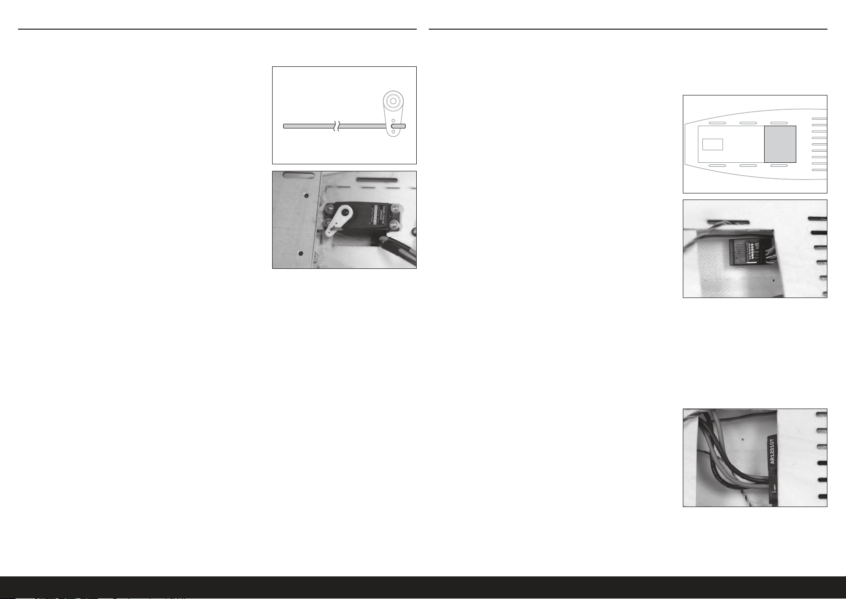
INSTALLAZIONE DEL MECCANISMO DI SGANCIO DEL TRAINO INSTALLAZIONE DEL RADIOCOMANDO
IMPORTANTE: se si sta installando la versione con alimentazione elettrica, saltare questa sezione e consultare la
sezione sull’installazione opzionale con alimentazione elettrica.
1. Installare il cavo del meccanismo di sgancio del traino al braccio
del servocomando.
2. Installare il servocomando del meccanismo di sgancio del traino
sul muso della fusoliera. Far scorrere il cavo del meccanismo di
sgancio attraverso il piccolo foro nella parte anteriore della cabina
di pilotaggio. Fissare il braccio al servocomando, verificando che
il cavo si apra completamente a un’estremità della corsa del
servocomando e si chiuda completamente all’estremità opposta
della corsa.
IMPORTANTE: anche se gli spoiler e l’elemento retrattile funzioneranno a una tensione di 7,2V, per una maggiore
durata e affidabilità si consiglia di regolare la tensione di alimentazione di questi componenti su 5,2V tramite l’utilizzo
di un regolatore della tensione di linea, come ad esempio il SPMVR5203.
Se l’elemento retrattile è lento nel funzionamento o non si ritrae completamente nella posizione di bloccaggio alla
tensione sottoposta a regolazione, collegare l’elemento retrattile direttamente al ricevitore a una tensione di 7,2V.
1. Tagliare con attenzione la parte posteriore del pavimento della
cabina di pilotaggio nella zona indicata.
2. Collegare i canali del carrello e degli spoiler dal ricevitore alle porte
di ingresso del regolatore.
3. Collegare le porte di uscita del regolatore al cavo del carrello e alla
prolunga a Y degli spoiler.
4. Dirigere tutti i cavi del servocomando dalla coda verso la parte
anteriore della fusoliera, mantenendoli più ordinati possibile.
Utilizzare fascette o un nastro di velcro per fissare i cavi nella
fusoliera.
5. Preparare sei cavi del servocomando da 460 mm (18 pollici): due
per gli alettoni, due per i flap e due per gli spoiler.
CONSIGLIO: utilizzare nastro di diversi colori avvolto alle estremità
dei cavi per poter distinguere quali cavi vanno alle rispettive
superfici di controllo.
6. Collegare tutti i cavi del servocomando alle rispettive porte del
ricevitore.
7. Montare il ricevitore sotto la parte posteriore del pavimento della
cabina di pilotaggio come indicato. Se necessario, utilizzare piccoli
pezzi di materiale espanso o nastro di velcro per mantenere in
posizione il ricevitore.
CONSIGLIO: se si desidera, tagliare dei fori nella parte posteriore
del pavimento della cabina di pilotaggio e indirizzare i cavi del
servocomando verso il ricevitore.
8. Montare temporaneamente le batterie del ricevitore il più possibile verso la parte anteriore della cabina di pilotaggio. La posizione della batteria sarà decisa in modo definitivo
dopo aver stabilito il corretto baricentro. La versione dell’aliante senza alimentazione avrà le batterie montate il più possibile in avanti, insieme a un peso aggiuntivo sul muso.
La versione con alimentazione elettrica non necessita di peso aggiuntivo sul muso per il bilanciamento e, a seconda della batteria utilizzata per il motore, può richiedere che le
batterie del ricevitore siano spostate verso la parte posteriore.
74IT
Page 75
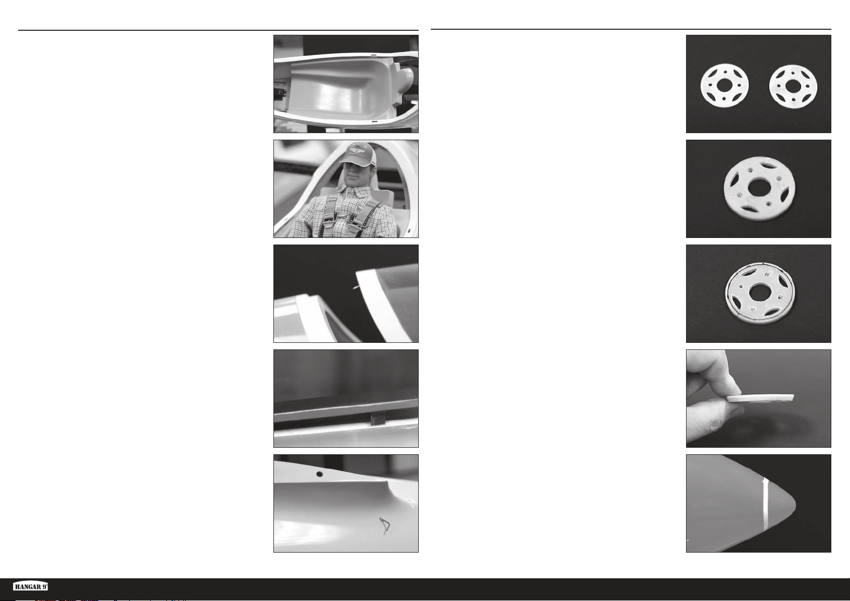
INSTALLAZIONE DELLA CABINA DI PILOTAGGIO
1. Installare la scocca in fibra di vetro della cabina di pilotaggio.
Premere leggermente ai lati della scocca per montarla tra e sotto
i lati sagomati della fusoliera. I fori nella scocca devono allinearsi
con i fori nella fusoliera. Non è necessario fissare la scocca alla
fusoliera. La scocca è removibile per consentire l’accesso alla
parte posteriore della fusoliera e alla zona inferiore della cabina di
pilotaggio.
INSTALLAZIONE OPZIONALE DEI SISTEMA DI ALIMENTAZIONE ELETTRICA
1. Rendere ruvido un lato di ciascuno dei pezzi del supporto motore
utilizzando una carta abrasiva, grana 80.
2. Se si desidera, installare una riproduzione opzionale del pilota
nella scocca per aggiungere maggiore realismo in scala. Non è
necessario fissare il pilota alla scocca.
CONSIGLIO: Hangar 9 ha stabilito un accordo con due società che
offrono riproduzioni personalizzate di piloti; www.warbirdpilots.
com negli Stati Uniti e www.tailoredpilots.com nel Regno Unito
mettono a disposizione riproduzioni di piloti molto dettagliate che si
adattano al modello ASH 31.
3. Installare la cappottina sulla fusoliera inserendo il perno sulla
parte anteriore della cappottina nel foro sulla parte anteriore
della fusoliera e ruotando la parte posteriore della cappottina in
basso in modo da aderire alla fusoliera, verificando che le alette di
allineamento laterali si inseriscano nei fori nella fusoliera.
2. Utilizzando colla epossidica “5 minuti”, incollare insieme i lati resi
ruvidi dei due pezzi del supporto motore, facendo in modo che i fori
si allineino in modo accurato. Pulire l’eventuale colla epossidica in
eccesso usando un panno di carta e alcool. Serrare insieme i pezzi
fino all’asciugatura completa della colla epossidica.
3. Tracciare una linea attorno a un lato del supporto a circa 1,5 mm
dal bordo esterno, come indicato.
4. Utilizzando la linea come guida, carteggiare per creare una
smussatura sul bordo del supporto. Carteggiare sopra il bordo,
dall’angolo posteriore verso la linea.
4. Far scorrere il blocco a cavo della cappottina posizionato sotto
la radice dell’ala sinistra, fino al fissaggio della cappottina. Può
essere necessario premere delicatamente sul retro della cappottina
per fare in modo che si chiuda completamente. Il blocco a cavo
determina volutamente uno stretto serraggio per impedire che si
allenti durante il volo.
ASH 31 6.4M ARF
5. Utilizzando nastro da 3 mm (1/8 di pollice), segnare una linea 25
mm all’indietro rispetto al muso della fusoliera.
75 IT
Page 76
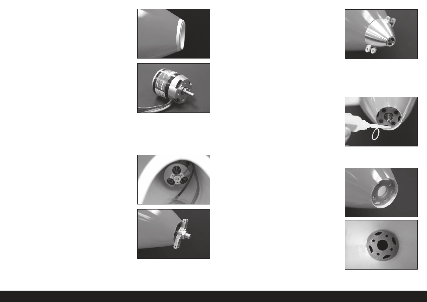
6. Tagliare con attenzione il muso dalla fusoliera utilizzando un
trapano con un disco da taglio. Non tagliare tutto il materiale
fino al nastro. Lasciare del materiale in eccesso da carteggiare
successivamente.
11. Premere in avanti il motore e serrare la vite centrale dell’ogiva
mentre si esercita una pressione sul motore. Serrare la vite in
modo tale da mantenere il motore in posizione, ma in modo da
consentire ancora la regolazione della posizione dell’ogiva nei
confronti della fusoliera.
12. Utilizzare l’ogiva per allineare correttamente il motore con il muso
della fusoliera.
7. Seguendo le istruzioni incluse con il motore, modificare
l’orientamento dell’albero motore per montare il motore sul retro
del supporto.
8. Fissare il supporto del motore al motore utilizzando le viti fornite
con il motore. Se necessario, utilizzare una fresa per smussi per
smussare i fori nella piastra di montaggio. Fare in modo che il
lato stretto dello smusso del bordo, carteggiato in precedenza nel
supporto, sia rivolto lontano dal motore.
9. Inserire il motore e il supporto nel muso della fusoliera dall’interno.
10. Premere l’adattatore dell’elica sull’albero motore e installare il
dado dell’elica senza serrarlo. Installare l’ogiva sopra l’adattatore
dell’elica. Verificare che l’ogiva sia collocata in modo completo
sopra l’adattatore. Installare la vite centrale dell’ogiva.
13. Quando l’allineamento è corretto, tenere il motore fermo agendo
dall’interno della fusoliera e rimuovere con attenzione l’assieme
dell’ogiva allentando la vite centrale dell’ogiva, facendo attenzione
a non spostare il motore. Far scorrere l’assieme dell’ogiva lontano
dall’albero motore.
14. Una volta rimossa l’ogiva, far aderire temporaneamente il
supporto motore alla fusoliera utilizzando un paio di gocce di colla
cianoacrilica a media viscosità, e un acceleratore di essiccazione,
attorno all’anello di montaggio.
15. Rimuovere le viti del supporto motore e rimuovere il motore
facendo attenzione a non liberare il supporto motore dalla fusoliera.
16. NON SALTARE QUESTO PASSAGGIO. Applicare una goccia
abbondante di colla epossidica attorno alla giunzione tra il supporto
e la fusoliera, sia davanti che dietro il supporto motore. Premere la
colla epossidica nella giunzione e lisciarla per formare un raccordo.
Prima di procedere, lasciare asciugare completamente la colla
epossidica.
76IT
Page 77
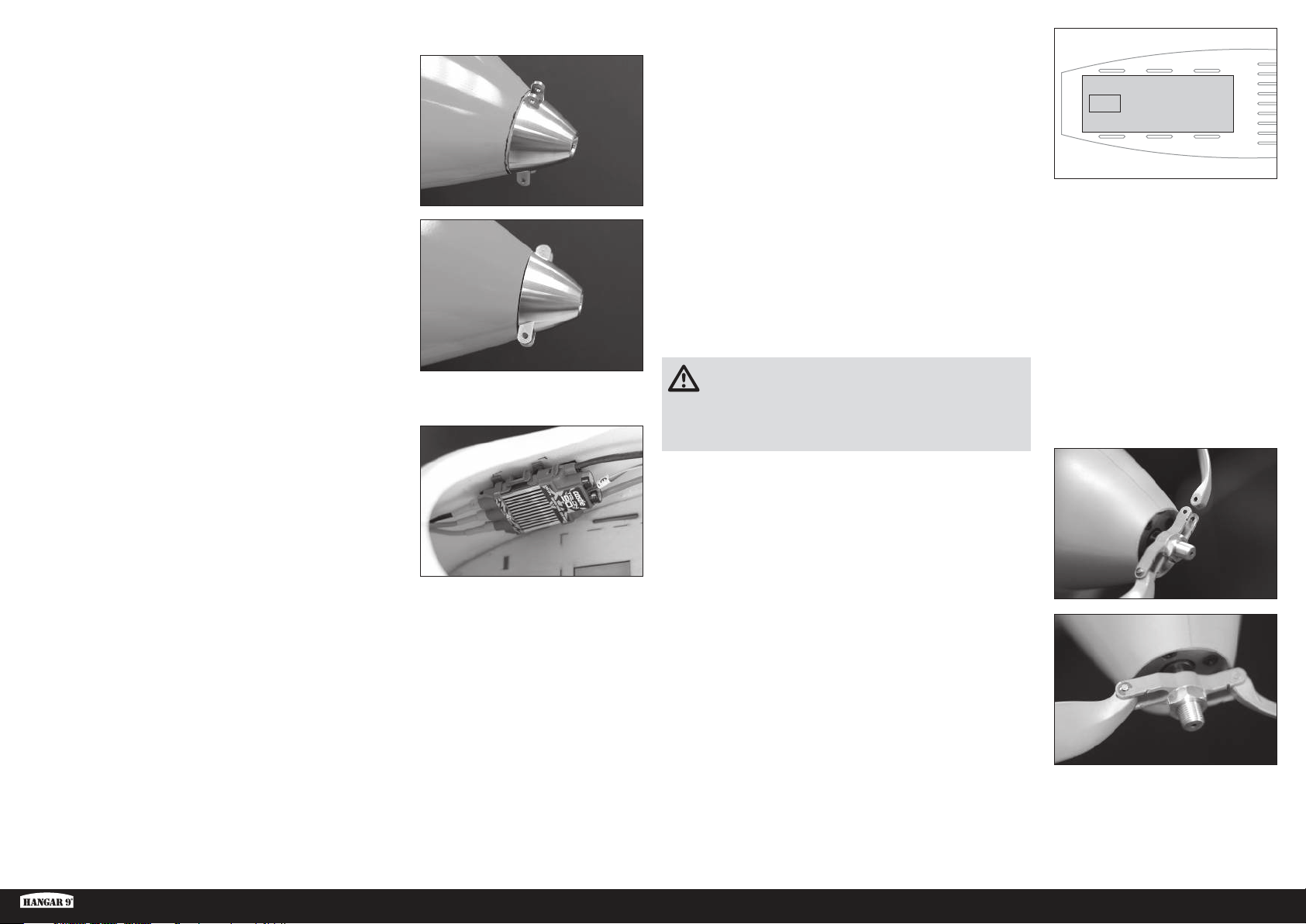
17. Installare temporaneamente l’assieme dell’ogiva e il motore.
18. Misurare e contrassegnare una linea attorno alla fusoliera 1 mm
indietro rispetto all’ogiva.
19. Rimuovere l’assieme dell’ogiva e il motore e carteggiare la parte
anteriore della fusoliera fino alla linea.
CONSIGLIO: utilizzare un blocco per carteggiatura per mantenere
dritta la parte anteriore della fusoliera. Rimuovere lentamente il
materiale e controllare spesso l’avanzamento. L’obiettivo è quello
di ottenere una linea perfettamente dritta con il retro dell’ogiva
attorno alla circonferenza della fusoliera.
20. Montare il motore sul supporto motore utilizzando un composto
frenafiletti medio.
21. Utilizzare nastro di velcro o nastro per servo per installare l’ESC
nella cabina di pilotaggio.
22. Collegare i cavi del motore all’ESC seguendo le istruzioni incluse
con il motore e l’ESC.
23. Collegare il cavo della manetta dell’ESC alla rispettiva porta del
ricevitore.
24. Tagliare e rimuovere la sezione indicata del pavimento della cabina
di pilotaggio.
25. Montare la batteria motore nel pavimento della cabina di pilotaggio
e fissarla utilizzando fascette di velcro attraverso i fori tagliati in
precedenza nel pavimento della cabina di pilotaggio.
26. Montare le batterie del ricevitore nella parte posteriore della cabina
di pilotaggio. Le batterie del ricevitore possono essere spostate
in modo adeguato per regolare il bilanciamento dell’aeromodello.
Quando si utilizzano i componenti consigliati del sistema di
alimentazione opzionale non è necessaria alcuna zavorra
aggiuntiva. Tuttavia, passare al paragrafo relativo al bilanciamento
dell’aeromodello per verificare il corretto baricentro.
ATTENZIONE: non tentare mai di far volare l’aeromodello
senza aver bilanciato correttamente l’aeromodello stesso. Un
aeromodello non bilanciato risulterà estremamente instabile e
potrebbe provocare un incidente. I danni dovuti ad un impatto non
sono coperti da garanzia.
27. Preparare il portapale installando l’albero conico e il dado. In
questa fase non serrare il dado.
28. Controllare che le pale dell’elica si adattino al portapale. La
pala deve muoversi liberamente quando il perno è installato. In
caso contrario, per consentire il libero movimento, carteggiare
leggermente le pale nel punto in cui entrano in contatto con il
portapale.
ASH 31 6.4M ARF
29. Una volta adattate le pale al portapale, utilizzare i perni e clip per
fissare le pale al portapale. Fare in modo che la parte anteriore
delle pale sia rivolta verso il lato intagliato del portapale.
30. Montare l’assieme sull’albero motore. Verificare che il portapale
possa muoversi liberamente e non entri in contatto con la parte
anteriore della fusoliera durante la sua completa rotazione. Per
serrare il dado e fissare il portapale e l’adattatore, usare una
chiave da 12 mm.
31. Installare l’ogiva, assicurandosi che si adatti agli intagli nel portapale dell’elica. Utilizzare la vite fornita con l’ogiva
e un cacciavite a croce n.1 per fissare l’ogiva all’adattatore.
CONSIGLIO: l’ogiva e le pale dell’elica possono essere verniciate per abbinarsi alla colorazione arancio
fluorescente del muso dell’aeromodello, utilizzando i prodotti citati nel paragrafo Conservazione della colorazione
fluorescente, rendendo l’ogiva e l’elica quasi invisibili durante il volo.
77 IT
Page 78
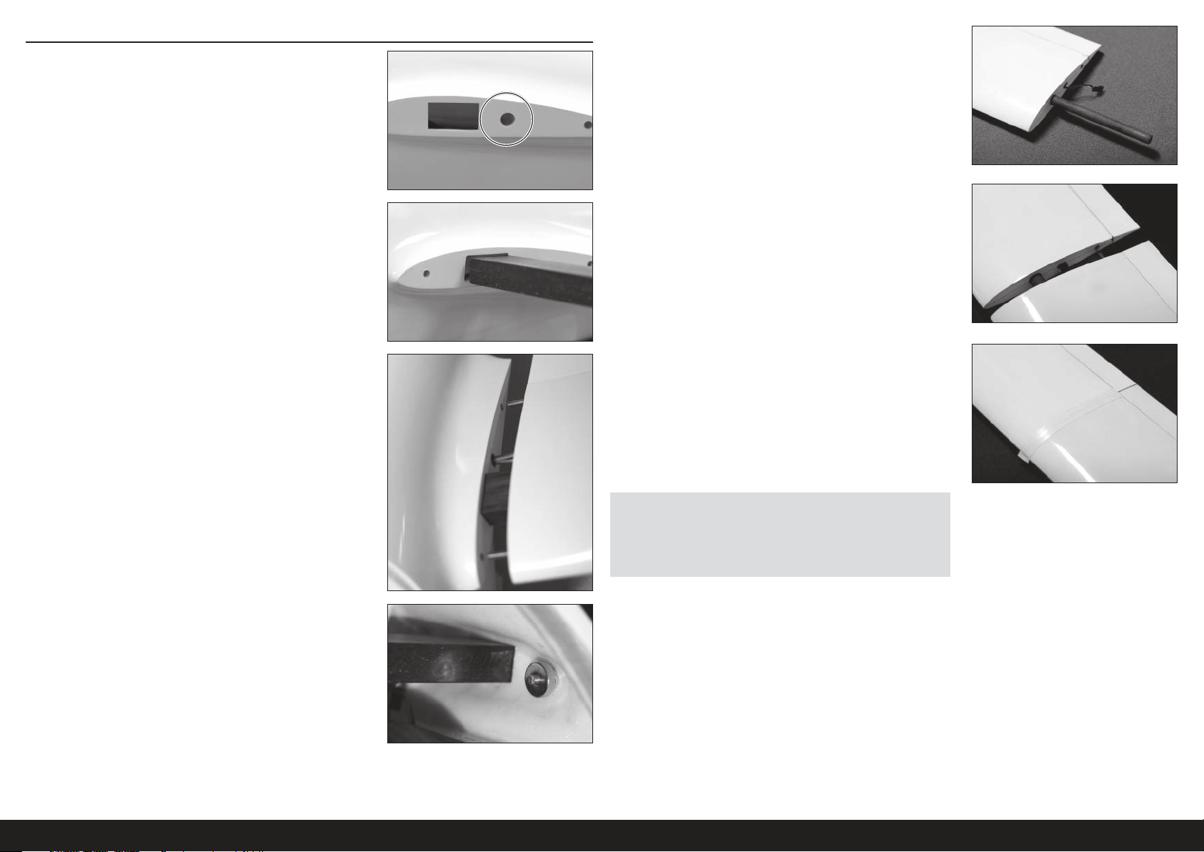
ASSEMBLAGGIO FINALE
1. Tagliare un foro nella radice dell’ala della fusoliera per i vari cavi
dei servocomandi provenienti dall’ala. Assicurarsi che il foro si
allinei con il foro tagliato in precedenza nella radice del pannello
interno dell’ala e sia grande a sufficienza per consentire il
passaggio dei connettori dei cavi dei servocomandi. Utilizzare carta
abrasiva per rimuovere eventuali bordi affilati attorno al foro.
2. Inserire il tubo di giunzione dell’ala nella fusoliera. Il tubo di
giunzione deve aderire perfettamente all’apertura sulla fusoliera.
Verificare che il tubo di giunzione sia centrato nella fusoliera.
5. Far scorrere un altro tubo esterno dell’ala nell’estremità esterna del
pannello interno dell’ala.
6. Far scorrere i pannelli esterni dell’ala sopra il tubo dell’ala fino a
quando il pannello esterno entra in contatto con il pannello interno.
Assicurarsi che il perno di allineamento dell’ala sia inserito nel foro
di allineamento dell’ala.
3. Far scorrere i pannelli interni delle ali sopra le estremità del tubo di
giunzione dell’ala, collegando i cavi dei servocomandi e inserendo
il perno di allineamento dell’ala nella fusoliera mentre si fa scorrere
il pannello.
4. Infilare il dado di bloccaggio dell’ala sul bullone prigioniero
filettato dell’ala dall’interno della fusoliera. Serrare a mano il dado
di bloccaggio, verificando che i vari cavi dei servocomandi non
rimangano pizzicati tra l’ala e la fusoliera.
7. Avvolgere la linea di giunzione tra il pannello esterno e quello
interno con nastro. Verificare che il nastro non interferisca con il
funzionamento delle superfici di controllo alari. Si consiglia l’utilizzo
di nastro per utilizzi elettrici in PVC. Abbiamo riscontrato che
questo nastro è più che sufficiente per mantenere intatti i pannelli
esterni delle ali in volo, anche durante manovre acrobatiche
energiche.
AVVISO: prima di fissare il nastro, verificare sempre che l’ala sia pulita,
asciutta e priva di polvere o detriti.
AVVISO: non riutilizzare il nastro dopo aver smontato l’ala. Utilizzare
sempre nastro nuovo ogni volta che l’ala viene smontata.
8. Installare l’aletta di estremità nel modo descritto nel paragrafo
Installazione dell’aletta di estremità.
9. Ripetere i passaggi 1-8 per l’altra ala.
10. Installare il guscio della cabina di pilotaggio, il pilota e la cappottina
sulla fusoliera.
78IT
Page 79
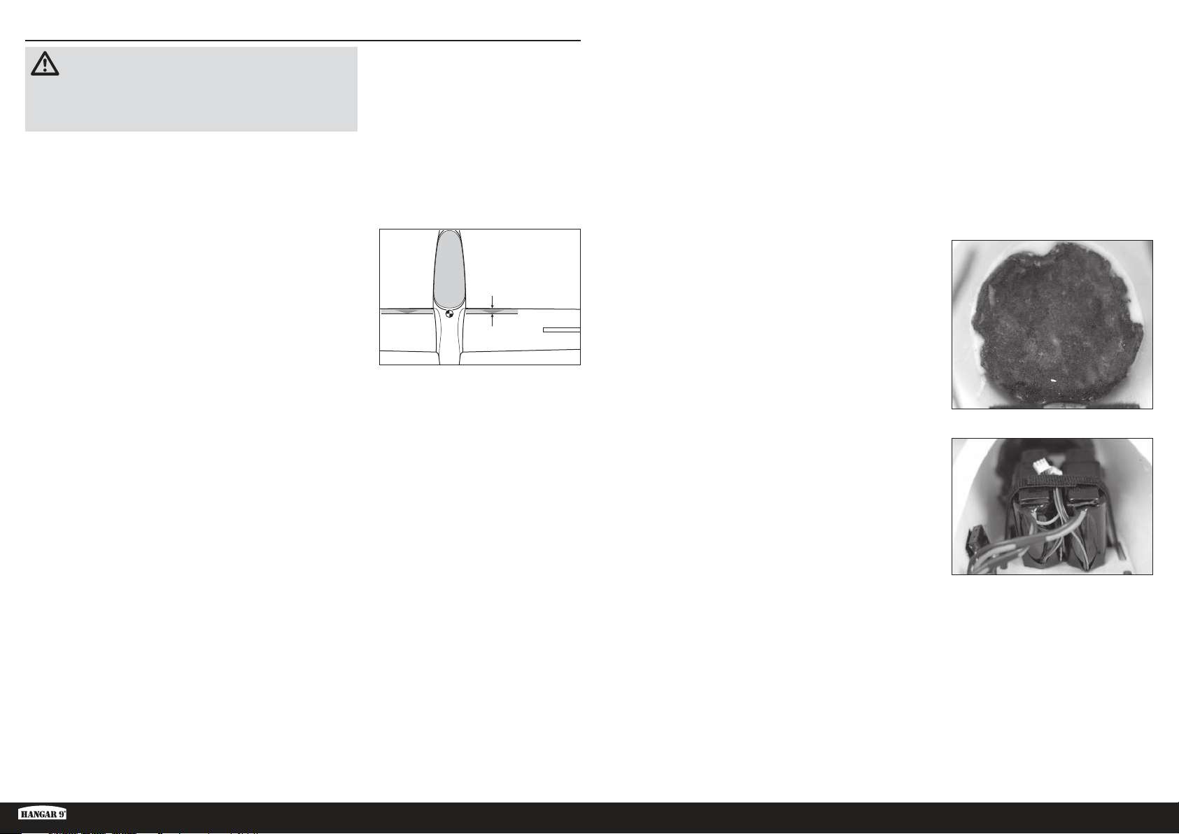
BILANCIAMENTO DELL’AEROMODELLO
ATTENZIONE: NON SALTARE QUESTO PASSAGGIO. Non
tentare mai di far volare l’aeromodello senza aver bilanciato
correttamente l’aeromodello stesso. Un aeromodello non bilanciato
risulterà estremamente instabile e potrebbe provocare un incidente. I
danni dovuti ad un impatto non sono coperti da garanzia.
1. Fissare i pannelli delle ali, la cappottina e i piani di coda alla
fusoliera. Assicurarsi di collegare i cavi provenienti dall’alettone,
dai flap e dagli spoiler ai cavi appropriati provenienti dal
ricevitore. Verificare che i cavi non rimangano esposti al di
fuori della fusoliera prima di serrare i bulloni delle ali. Prima del
bilanciamento il modello deve avere l’alimentazione in posizione
OFF e trovarsi in uno stato diverso da quello di pronto al volo.
2. La posizione consigliata del baricentro (CG) per il modello si trova
a 60–85 mm dietro il bordo di attacco dell’ala a livello della radice.
Contrassegnare la posizione del baricentro sulle ali tramite nastro
o un pennarello. Metti in equilibrio verticale il tuo modello con le
dita o usando un supporto di bilanciamento che sostiene il velivolo
sulle marcature realizzate al fondo dell’ala.
3. Sostenere in posizione dritta l’aeromodello a livello dei segni
effettuati sulle ali, servendosi delle dita o utilizzando un supporto
per bilanciamento disponibile in commercio.
Se si sta realizzando la versione senza alimentazione trainata o
lanciata, procedere al passaggio 5.
23/8–35/16 inches
(60–85 mm)
Aggiungere zavorra al muso dell’aeromodello fino a quando la
fusoliera si posiziona in orizzontale o con il muso leggermente
rivolto verso il basso sul supporto di bilanciamento.
CONSIGLIO: fissare con nastro una busta di plastica sulla parte
esterna del muso della fusoliera e aggiungere peso, come
ad esempio pallini di piombo o il prodotto “Liquid Gravity”
della Deluxe Materials (DLMBD38), alla borsa fino a quando
l’aeromodello risulta bilanciato.
5. Rimuovere le ali, la cappottina e le batterie di volo dalla fusoliera e,
prestando attenzione, far rimanere la fusoliera in piedi sul proprio
muso.
6. Miscelare la zavorra di cui al passaggio 5 con colla epossidica
e riempitivo in microsfere e aggiungere il composto all’interno
del muso della fusoliera. Lasciare asciugare completamente la
miscela.
CONSIGLIO: un’alternativa all’aggiunta di zavorra direttamente
sulla fusoliera consiste nell’utilizzare l’ogiva fornita da Hangar
9 RV-4 (HAN488509) come stampo per conservare la miscela
colla epossidica/zavorra fino alla sua completa asciugatura.
Questa ogiva corrisponde quasi perfettamente alla forma del
muso dell’aliante ASH. Versare la miscela della zavorra all’interno
dell’ogiva. Dopo la completa asciugatura, la miscela può essere
rimossa dall’ogiva e montata in sicurezza sul muso della fusoliera
con colla epossidica.
Riportare le batterie di volo nella loro posizione nella cabina di
pilotaggio e fissarle in posizione.
4. Se si sta realizzando la versione con alimentazione elettrica,
spostare le batterie del ricevitore in avanti o all’indietro nella cabina
di pilotaggio fino a quando l’aeromodello si posiziona in orizzontale
o con il muso leggermente rivolto verso il basso sul supporto di
bilanciamento. Una volta raggiunto il corretto baricentro, montare le
batterie del ricevitore sulla fusoliera utilizzando del nastro di velcro.
Passare al paragrafo Corse dei comandi.
CONSIGLIO: se non si riesce a ottenere il punto di bilanciamento
corretto con le batterie del ricevitore in posizione completamente
avanzata, aggiungere un peso autoadesivo fino a quando
l’aeromodello risulta bilanciato.
ASH 31 6.4M ARF
79 IT
Page 80

CORSE DEI COMANDI
1. Accendere la trasmittente e la ricevente del modello. Controllare il movimento del timone con il radiocomando.
Quando si sposta lo stick a destra il timone si deve spostare verso destra. Se necessario intervenire sul Reverse
del tramettitore.
2. Controllare il movimento dell’elevatore con il radiocomando. Spostando lo stick dell’elevatore verso il basso del
trasmettitore, l’elevatore sul modello si sposterà in alto.
3. Controllare il movimento degli alettoni con il radiocomando. Spostando lo stick degli alettoni verso destra, l’alettone
destro andrà verso l’alto e quello sinistro verso il basso.
4. Utilizzare un righello per regolare la corsa dell’elevatore, degli alettoni e del timone.
Superficie Rateo Direzione Corsa
Atterraggio/In quota
Alettoni
Crociera/Lancio
Alto
Elevatore
Basso
Timone Alto
Atterraggio Verso il basso 25–30mm
Flaperon
• In modalità Atterraggio/In quota, gli alettoni si muoveranno in modo indipendente dai flaperon
• In modalità Atterraggio/In quota, inclinare verso il basso l’intero bordo di uscita (flaperon e alettoni) di 3-4 mm.
• In modalità Crociera/Lancio, accoppiare gli alettoni e i flaperon per un completo controllo del rollio.
• In modalità Crociera/Lancio, flettere nuovamente verso l’alto l’intero bordo di uscita (flaperon e alettoni) di 3-4 mm.
• Usare un elemento scorrevole per controllare la corsa dei flaperon in modo tale che la quantità di spostamento
possa essere variata.
• Si consiglia di abbassare i flaperon di 10 mm durante il decollo ROG (Rise Off Ground) e durante l’aereotraino.
• Impostare la corsa del timone a una quantità che non vincoli il servo.
• Impostare la corsa massima del flaperon a una quantità che non vincoli il servo.
Queste sono indicazioni generali misurate durante le nostre prove. Si possono impostare corse differenti per ottenere lo
stile di volo preferito.
Le regolazioni di corsa e i sub-trim non sono elencati e si possono regolare secondo le proprie preferenze. Installare
sempre le squadrette a 90 gradi rispetto alla linea centrale del servo. Lasciare i sub-trim come ultima risorsa per
centrare i servi.
Effettuare sempre nuovamente la procedura di binding (connessione) del radiocomando dopo l’impostazione di tutte le
corse dei comandi per impedire che i servocomandi si spostino verso i propri fine corsa prima del collegamento della
trasmittente con il ricevitore.
Crociera/Lancio
Verso l’alto 16mm
Verso il basso 12mm
Verso l’alto 18–20mm
Verso il basso 14mm
Verso l’alto 9mm
Verso il basso 7mm
Verso l’alto 7mm
Verso il basso 5mm
Destra 35–45mm
Sinistra 35–45mm
Verso l’alto 18–20mm
Verso il basso 14mm
LISTA DEI CONTROLLI PRIMA DEL VOLO
• Caricare la trasmittente, il ricevitore e le batterie del motore. Seguire eventuali istruzioni fornite con il caricabatterie.
Seguire tutte le istruzioni del produttore relative ai componenti elettronici.
• Controllare l’installazione radio accertandosi che tutte le superfici di controllo (alettoni, elevatore, timone e motore) si
muovano nel verso corretto e con la giusta corsa.
• Controllare tutte le squadrette di controllo, squadrette dei servi e forcelle, per accertarsi che siano ben fissate e in
buone condizioni.
• Prima di ogni sessione di volo e specialmente con un modello nuovo, eseguire una prova di portata del
radiocomando. Per ulteriori spiegazioni si veda il manuale del radiocomando.
CONTROLLI DI VOLO GIORNALIERI
• Controllare la tensione della batteria del trasmettitore. Non volare se la tensione è inferiore a quella indicata dal
costruttore; in caso contrario si potrebbe avere un incidente distruttivo.
• Controllare tutti i rinvii, le viti, i dadi e i bulloni prima di ogni giornata di volo. Verificare che non ci siano impedimenti
nelle corse dei comandi e che tutte le parti siano fissate bene.
• Verificare che le superfici mobili si muovano nel verso giusto.
• Eseguire una prova di portata a terra prima di una sessione di volo giornaliera.
• Tutti i cavi dei servocomandi e i connettori dei cablaggi degli interruttori devono essere fissati al ricevitore.
GARANZIA
Periodo di garanzia
Garanzia esclusiva - Horizon Hobby, LLC (Horizon) garantisce che il prodotto acquistato (il “Prodotto”) sarà privo di
difetti relativi ai materiali e di eventuali errori di montaggio alla data di acquisto. Il periodo di garanzia è conforme alle
disposizioni legali del paese nel quale il prodotto è stato acquistato. Tale periodo di garanzia ammonta a 6 mesi e si
estende ad altri 18 mesi dopo tale termine.
Limiti della garanzia
(a) La garanzia è limitata all’acquirente originale (Acquirente) e non è cedibile a terzi. L’acquirente ha il diritto a far
riparare o a far sostituire la merce durante il periodo di questa garanzia. La garanzia copre solo quei prodotti acquistati
presso un rivenditore autorizzato Horizon. Altre transazioni di terze parti non sono coperte da questa garanzia. La prova
di acquisto è necessaria per far valere il diritto di garanzia. Inoltre, Horizon si riserva il diritto di cambiare o modificare i
termini di questa garanzia senza alcun preavviso e di escludere tutte le altre garanzie già esistenti.
(b) Horizon non si assume alcuna garanzia per la disponibilità del prodotto, per l’adeguatezza o l’idoneità del prodotto a
particolari previsti dall’utente. È sola responsabilità dell’acquirente il fatto di verificare se il prodotto è adatto agli scopi
da lui previsti.
(c) Richiesta dell’acquirente – spetta soltanto a Horizon, a propria discrezione riparare o sostituire qualsiasi prodotto
considerato difettoso e che rientra nei termini di garanzia. Queste sono le uniche rivalse a cui l’acquirente si può
appellare, se un prodotto è difettoso.
Horizon si riserva il diritto di controllare qualsiasi componente utilizzato che viene coinvolto nella rivalsa di garanzia.
Le decisioni relative alla sostituzione o alla riparazione sono a discrezione di Horizon. Questa garanzia non copre dei
danni superficiali o danni per cause di forza maggiore, uso errato del prodotto, un utilizzo che viola qualsiasi legge,
regolamentazione o disposizione applicabile, negligenza, uso ai fini commerciali, o una qualsiasi modifica a qualsiasi
parte del prodotto.
Questa garanzia non copre danni dovuti ad un’installazione errata, ad un funzionamento errato, ad una manutenzione
o un tentativo di riparazione non idonei a cura di soggetti diversi da Horizon. La restituzione del prodotto a cura
dell’acquirente, o da un suo rappresentante, deve essere approvata per iscritto dalla Horizon.
80IT
Page 81
Limiti di danno
Horizon non si riterrà responsabile per danni speciali, diretti, indiretti o consequenziali; perdita di profitto o di
produzione; perdita commerciale connessa al prodotto, indipendentemente dal fatto che la richiesta si basa su un
contratto o sulla garanzia. Inoltre la responsabilità di Horizon non supera mai in nessun caso il prezzo di acquisto
del prodotto per il quale si chiede la responsabilità. Horizon non ha alcun controllo sul montaggio, sull’utilizzo o sulla
manutenzione del prodotto o di combinazioni di vari prodotti. Quindi Horizon non accetta nessuna responsabilità per
danni o lesioni derivanti da tali circostanze. Con l’utilizzo e il montaggio del prodotto l’utente acconsente a tutte le
condizioni, limitazioni e riserve di garanzia citate in questa sede.
Qualora l’utente non fosse pronto ad assumersi tale responsabilità associata all’uso del prodotto, si suggerisce di
restituire il prodotto intatto, mai usato e immediatamente presso il venditore.
Indicazioni di sicurezza
Questo è un prodotto sofisticato di hobbistica e non è un giocattolo. Esso deve essere manipolato con cautela, con
giudizio e richiede delle conoscenze basilari di meccanica e delle facoltà mentali di base. Se il prodotto non verrà
manipolato in maniera sicura e responsabile potrebbero risultare delle lesioni, dei gravi danni a persone, al prodotto o
all’ambiente circostante. Questo prodotto non è concepito per essere usato dai bambini senza una diretta supervisione
di un adulto. Il manuale del prodotto contiene le istruzioni di sicurezza, di funzionamento e di manutenzione del
prodotto stesso. È fondamentale leggere e seguire tutte le istruzioni e le avvertenze nel manuale prima di mettere in
funzione il prodotto. Solo così si eviterà un utilizzo errato e si preverranno incidenti, lesioni o danni.
Domande, assistenza e riparazioni
Il vostro negozio locale e/o luogo di acquisto non possono fornire garanzie di assistenza o riparazione senza previo
colloquio con Horizon. Questo vale anche per le riparazioni in garanzia. Quindi in tale casi bisogna interpellare un
rivenditore, che si metterà in contatto subito con Horizon per prendere una decisione che vi possa aiutare nel più breve
tempo possibile.
Manutenzione e riparazione
Se il prodotto deve essere ispezionato o riparato, si prega di rivolgersi ad un rivenditore specializzato o direttamente ad
Horizon. Il prodotto deve essere imballato con cura. Bisogna far notare che i box originali solitamente non sono adatti
per effettuare una spedizione senza subire alcun danno. Bisogna effettuare una spedizione via corriere che fornisce
una tracciabilità e un’assicurazione, in quanto Horizon non si assume alcuna responsabilità in relazione alla spedizione
del prodotto. Inserire il prodotto in una busta assieme ad una descrizione dettagliata degli errori e ad una lista di tutti
i singoli componenti spediti. Inoltre abbiamo bisogno di un indirizzo completo, di un numero di telefono per chiedere
ulteriori domande e di un indirizzo e-mail.
Garanzia e riparazione
Le richieste in garanzia verranno elaborate solo se è presente una prova d’acquisto in originale proveniente da un
rivenditore specializzato autorizzato, nella quale è ben visibile la data di acquisto. Se la garanzia viene confermata,
allora il prodotto verrà riparato o sostituito. Questa decisione spetta esclusivamente a Horizon Hobby.
Riparazioni a pagamento
Se bisogna effettuare una riparazione a pagamento, effettueremo un preventivo che verrà inoltrato al vostro rivenditore.
La riparazione verrà effettuata dopo l’autorizzazione da parte del vostro rivenditore. La somma per la riparazione dovrà
essere pagata al vostro rivenditore. Le riparazioni a pagamento avranno un costo minimo di 30 minuti di lavoro e in
fattura includeranno le spese di restituzione. Qualsiasi riparazione non pagata e non richiesta entro 90 giorni verrà
considerata abbandonata e verrà gestita di conseguenza.
CONTATTI PER LA GARANZIA E L’ASSISTENZA
Paese di
acquisto
EU
Horizon Hobby Telefon/Email Adresse Adresse
Horizon Technischer Service
Horizon Hobby GmbH
+49 (0) 4121 2655 100
[email protected]
Hanskampring 9
D 22885 Barsbüttel, Germany
INFORMAZIONI SULLA CONFORMITÀ PER L’UNIONE EUROPEA
Dichiarazione di conformità EU: Horizon Hobby, LLC con la presente dichiara che il prodotto è conforme ai
requisiti essenziali e ad altre disposizioni rilevanti della direttiva EMC.
content/support-render-compliance.
Una copia della dichiarazione di conformità per l’Unione Europea è disponibile a: http://www.horizonhobby.com/
ISTRUZIONI PER LO SMALTIMENTO DI RAEE DA PARTE DI UTENTI DELL’UNIONE EUROPEA
Questo prodotto non deve essere smaltito assieme ai rifiuti domestici. È responsabilità dell’utente lo
smaltimento di tali rifiuti, che devono essere portati in un centro di raccolta predisposto per il riciclaggio
di rifiuti elettrici eapparecchiature elettroniche. La raccolta differenziata eil riciclaggio di tali rifiuti
provenienti da apparecchiature nel momento dello smaltimento aiuteranno apreservare le risorse
naturali egarantiranno un riciclaggio adatto aproteggere il benessere dell’uomo edell’ambiente. Per
smaltimento rifiuti oil negozio presso il quale èstato acquistato il prodotto.
maggiori informazioni sui punti di riciclaggio si invita acontattare l’ufficio locale competente, il servizio di
ATTENZIONE: Le riparazioni a pagamento sono disponibili solo sull’elettronica e sui motori. Le riparazioni a
livello meccanico, soprattutto per gli elicotteri e le vetture RC, sono molto costose e devono essere effettuate
autonomamente dall’acquirente.
ASH 31 6.4M ARF
10/15
81 IT
Page 82
PEZZI DI RICAMBIO COMPONENTI NECESSARI PER L’ASSEMBLAGGIO
Componente n. Descrizione
EFLG630S Elemento retrattile elettrico
HAN318501 Fusoliera
HAN318502 Pannello interno dell’ala lato sinistro
HAN318503 Pannello interno dell’ala lato destro
HAN318504 Pannello esterno dell’ala lato sinistro
HAN318505 Pannello esterno dell’ala lato destro
HAN318506 Aletta di estremità lato sinistro
HAN318507 Aletta di estremità lato destro
HAN318508 Ruote per le estremità alari
HAN318509 Stabilizzatore
HAN318510 Tubo di giunzione in carbonio dell’ala
HAN318511 Aste esterne delle ali
HAN318512 Tubi di giunzione delle alette di estremità
HAN318513 Piastre di copertura dei servocomandi (6)
HAN318514 Cabina di pilotaggio
HAN318515 Sedile
HAN318516 Timone
HAN318517 Componenti del carrello di atterraggio
HAN318518 Sportelli del carrello di atterraggio
HAN318519 Ruotino di coda
HAN318520 Cerniere (4)
HAN318521 Coperture degli aerofreni (2)
HAN318522 Fermi dell’ala (2)
Tutte le versioni
N. richiesto Componente n. Descrizione
1 SPMAR12310T PowerSafe Tele RX 12 canali AR12310T
4 SPMSA5060 Mini servocomando alta tensione metallico H-T / H-S A5060
2 SPMSA7050 Servocomando alta tensione MG elevata coppia ala sottile A7050
3 SPMA3003 Estensione servo 300 mm
8 SPMA3004 Estensione servo 460 mm
5 SPMA3005 Estensione servo 600 mm
4 SPMA3007 Estensione servo 1200 mm
1 SPMA3008 Prolunga a Y Heavy Duty, 150 mm
2 SPMB4000LPRX Batteria per ricevitore da 7,4 V Li-Po, 4.000 mAh
1 SPMA3054 Morsetti servocomando (25)
1 SPMVR5203 Regolatore duplice uscita VR5203
Versione senza alimentazione, trainata-lanciata
N. richiesto Componente n. Descrizione
1 SPMSA7040 Servocomando alta tensione per elementi retrattili A7040
DLMBD38 Prodotto per aggiunta peso “Liquid Gravity”
Versione con alimentazione elettrica
N. richiesto Componente n. Descrizione
1 CSE010009700 ESC BL Talon 90-Amp 25 V con BEC 20amp
1 EFLM4060B Motore brushless a cassa rotante Power 60, 470Kv
1 EFLP16080FA Ogiva, 45 mm: ASW 20 4,7 m
1 HAN495512 Elica 16 x 10: ASW 20 4,7 m
1 KXSB40006S40 Batteria F-Tek 4000mAh 6S 40C, EC5, con LED
ARTICOLI OPZIONALI
Componente n. Descrizione
SPMA3008 Prolunga a Y Heavy Duty, 150 mm
SPMAS3000 Modulo di stabilizzazione AS3000 AS3X
TAM85013 Smalto spray trasparente TS-13
TAM86024 Bomboletta spray arancio fluorescente PS-24 100 ml
TAM87044 Primer bianco 180 ml
ARTICOLI AGGIUNTIVI NECESSARI
Descrizione
Trasmittente 6 canali o più
Caricabatterie LiPo
82IT
Page 83

Page 84

© 2018 Horizon Hobby, LLC
Hangar 9, DSMX, PowerSafe, ModelMatch, EC5, Dynamite and the Horizon Hobby logo are trademarks or registered trademarks of Horizon Hobby, LLC.
The Spektrum trademark is used with permission of Bachmann Industries, Inc.
ASH 31 and the associated logos and body designs are trademarks or registered trademarks of Alexander Schleicher GmbH & Co. and are used with permission by Horizon Hobby,
LLC.
All other trademarks, service marks and logos are the property of their respective owners.
Created 8/18 50749 HAN4995
 Loading...