

Page 1

User’s Manual HPS
Introduction
Introduction
The HPS from HandyWave is a ready-to-use short-range wireless connectivity solution for
industrial. It provides the most economic and powerful way of cable replacement for the serial
communication systems including RS-232, RS-422, and RS-485.
Features
z Supports DIN-RAIL an d Wall Mount
z Supports Bluetooth Serial Port Profile and Generic Access Profile
z No need of external host and software
z Easy of installation and use
z Supports configuration of the local device
z Supports configuration of the remote device via Over-the-Air
z Easy of maintenance
z Supports up to 100 meter (Line of Sight)
z Supports RS-232, RS-422, and RS-485
z Supports Point-to-Point and Point-to-Multipoint Topology
Specifications
z Standard: Bluetooth Specification Version 1.2 and/or above
z Operation Frequency: 2.4GHz ISM Band
z Transmitted Power: Max 12.4dBm (Conducted)
z Received Sensitivity: More than –80dBm
z Power Supply: DC +5 ~ +30V
z Current Consumption: Up to 200mA at DC 5V
z Operation Temperature: -20 ~ 60 °C
z Dimension: 52.5mm (W) x 86.0mm (D) x 58.0mm (H)
z Baud Rate: 1.2, 2.4, 4.8, 9.6, 19.2, 38.4, 57.6, and 115.2Kbps
z Antenna Interface:
z Signal Interface: 14 Terminals and screws
Left-handed SMA Female Connector
Contents
z HPS 2 EA
z Antenna 2 EA
z A User’s Manual
HandyWave Co., Ltd. 1/5
202-4 Yatap-dong, Bundang-gu, Seongnam City, Gyunggi Province 463-070, Republic of Korea
Tel: 82-31-709-8900, Fax: 82-31-708-9455
http://www.handywave.com
2006 HandyWave Co., Ltd. All rights reserved.
Page 2
User’s Manual HPS
Hardware Setup
Hardware Setup
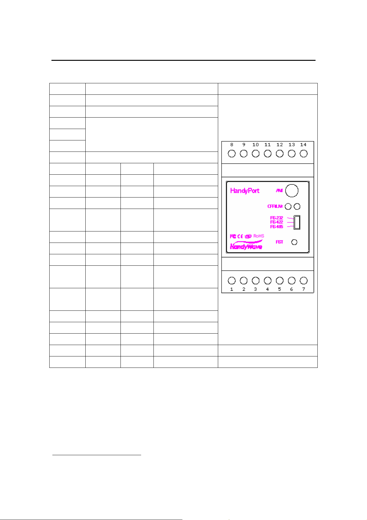
Interface
Items Description
ANT Antenna Interface
OPR/LNK LED Display
RS-232
RS-422
RS-485
RST Configuration Button
Pin # Signal Direction Descriptions
1 TxD O1 TxD for RS-232
2 RxD I2 RxD for RS-232
3 RTS/DTR O RTS/DTR for RS-232
4 CTS/DSR I CTS/DSR for RS-
5 GND Common Signal Ground
6 GND Common Power Ground
7 Power I Power Supply
Operation Selection Switch for
RS-232,
RS-422, or RS-485
232
Figure
8 TX+/TRX+ I/O TX+: RS-422
TRX+: RS-485
9 TX-/TRX- I/O RX-: RS-422
TRX-: RS-485
10 RX+ I RX+: RS-422
11 RX- I RX-: RS-422
12 GND Common Signal Ground
13 EoR+ O End of Resistor3 + RS-485 Only
14 EoR- I End of Resistor – RS-485 Only
Quick Installation Guide
Step 1: Assemble a provided antenna to the antenna port on the HandyPort.
Step 2: Select a serial interface using the operation selectio n switch on the HandyPort.
Step 3: Make connections using 14 terminals and screws for power and serial interface.
Step 4: Configure the HandyPort, if necessary.
1
O: Output
2
I: Input
3
End of Resistor: If the HandyPort is required an end of resistor , you can make a loop between
EoR+ and EoR-. It is only for RS-485.
HandyWave www.handywave.com 2/5
Page 3
User’s Manual HPS
Hardware Setup
Connection Overview for Power and Serial Interfaces
Power
Pin # Signal Descriptions
6 GND Power Ground
7 Power Power Supply (DC +5V ~ +30V)
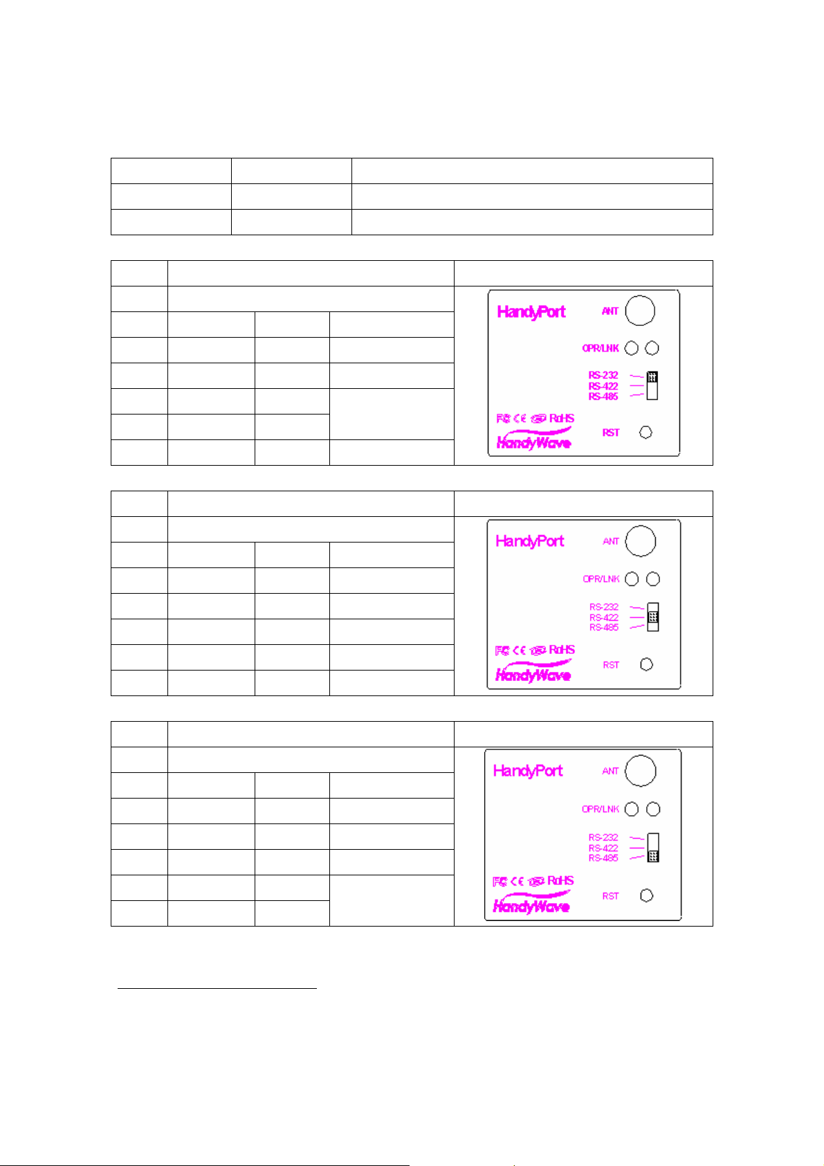
RS-232
Items Location Figure
Switch RS-232
Pin # Signal Direction Remarks
1 TxD O1
2 RxD I2
3 RTS/DTR O
4 CTS/DSR I
5 GND Common
Please see the
3
below.
RS-422
Items Location Figure
Switch RS-422
Pin # Signal Direction Remarks
8 TX+ TX+
9 TX- TX-
10 RX+ RX+
11 RX- RX-
12 GND GND
RS-485
Items Location Figure
Switch RS-422
Pin # Signal Direction Remarks
8 TRX+ I/O
9 TRX- I/O
12 GND Common
13 EoR+ O
14 EoR- I
1
O: Output
2
I: Input
3
Flow Control (RTS/CTS and/or DTR/DSR): You can use the flow control for RS-232. To use
the flow control, you have to set the flow control for the HandyPort and DTE accordingly.
4
EoR (End of Resistor): If the HandyPort is required an end of resistor, you can make a loop
between EoR+ and EoR-. It is only for RS-485.
HandyWave www.handywave.com 3/5
Please see the
4
below.
Page 4

User’s Manual HPS
Configuration
Configuration
You can change the configuration of HandyPort using HyperTerminal or similar terminal
emulator.
HyperTerminal Settings
z COM Port Settings: 9600 8-N-1, Flow Control: None (Factory Settings of HandyPort)
z Emulation: VT100
Switch Location
To configure the HandyPort, the switch location shall be in RS-232.
Start Configurations
Step 1: Make a RS-232 connection between the PC and HandyPort. And supply power for
HandyPort.
Step 2: Open a Hyper Terminal at the PC and set it up.
Step 3: Push the RST button on HandyPort. If you enter the configuration mode successfully,
LNK LED will be flashing every second.
Step 4: Hit the <Enter> key, 5 second later.
Step 5: Change the config uration of Ha ndyPort with commands, if necessary.
Usage Printing
If you are in the configuration mode, type “?<Enter>” for listing commands. If you want to know
the usage of specific command, type “?[command]<Enter>”. All commands and parameters are
case sensitive. Therefore, you have to use the capital letter for command s and parameters.
End Configurations
After finishing the configuration, you have to execute a command “X” to apply changes and exit
the configuration mode.
Frequently Used Commands
Command Syntax Description
A ABD_ADDR<CR> Change the remote device address
B BBR[D]<CR> Change the baud rate
M
P
S
V
HandyWave www.handywave.com 4/5
MMode<CR>
PPA[D]<CR>
SST[D]<CR>
V
Change the connection mode
Change the parity bit
Change the stop bits
Display the device information
Page 5

User’s Manual HPS
Configuration
Note.
This device complies with Part 15 of the FCC Rules. Operation is subject to the following two
conditions: (1) This device may not cause harmful interference, and (2) this device must accept
any interference received, including interference that may cause undesired operation.
Note.
Modifications not expressly approved by this company could void the user’s authority to operate
the equipment.
Note.
This equipment has been tested and found no comply with the limits for a Class B digital device,
pursuant to part 15 of the FCC rules. These limits are designed to provide reasonable protection
against harmful interference in a residential installation. This equipment generates, uses and
can radiate radio frequency energy and, if not installed and used in accordance with the
instructions, may cause harmful interference to radio communications. However, there is no
guarantee that interference will not occur in a particular installation. If this equipment does
cause harmful interference to radio or television reception, which can be determined by turning
the equipment off and on, the user is encouraged to try to correct the interference by one or
more of the following measures;
- Reorient or relocate the receiving antenna.
- Increase the separation between the equipment and receiver.
- Connect the equipment into an outlet on a circuit different from that to which the receiver
is connected
- Consult the dealer or an experienced radio/TV technician for help.
INFORMATION TO USER
The users manual or instruction manual for an intentional or unintentional radiator shall caution
the user that changes or modifications not expressly approved by the party responsible for
compliance could void the user’s authority to operate the equipment.
CAUTION
FCC Radio-Frequency Exposure Statement This equipment generates and radiates radio
frequency energy. In order to comply with FCC radio-frequency radiation exposure guidelines
for an uncontrolled environment, this equipment has to be installed and operated while
maintaining a minimum body to antenna distance of 20cm. User are not permitted to make
changes or modify the system in any way. The antenna(s) used for this transmitter must be
installed to provide a separation distance of at least 20cm from all persons and must not be
collocated or operating in conjunction with any other antenna or transmitter.
HandyWave www.handywave.com 5/5
 Loading...