

Page 1

INSTRUCTION MANUAL
42” (107cm)
TOWED
LAWN SWEEPER
MODEL NO: THTLS42 -- PRODUCT NO: 1938210001
EN - ORIGINAL INSTRUCTIONS
ASSEMBLY REQUIRED - MINIMUM TWO PERSONS
SAVE THESE INSTRUCTIONS
SPARES & SUPPORT: 01793 333212
FOR YOUR SAFETY
Please read & understand this manual, paying attention to the safety instructions, before use.
Incorrect use of the product could put the operator or machine in danger.
Whilst every effort has been made to ensure the accuracy of information contained in this manual, our
policy of continuous improvement determines the right to make modifications without prior warning.
Images used are for illustration purposes only
V1 21-05-2019
Page 2

Copyright Notice
Copyright © Handy Distribution
Permission is granted to reproduce this publication for personal & educational use only.
Commercial copying, redistribution, hiring or lending is prohibited.
No part of this publication may be stored in a retrieval system or transmitted in any other form or means without
written permission from Handy Distribution.
In all cases this copyright notice must remain intact.
Page 3

CONTENTS
SPECIFICATIONS
IMPORTANT INFORMATION
GENERAL SAFETY INSTRUCTIONS
ABOUT YOUR LAWN SWEEPER
COMPONENTS
ASSEMBLY
OPERATION
MAINTENANCE
STORAGE
PARTS DIAGRAM & LIST
WARRANTY
CE DECLARATION OF CONFORMITY
ASSEMBLY IS REQUIRED - MINIMUM TWO PERSONS
This product requires assembly before use. See “Assembly” section for instructions. Because of the
weight and/or size of the trailer, it is recommended that another adult be present to assist with the
assembly. INSPECT ALL COMPONENTS closely upon receipt to make sure no components are missing or
damaged.
If you require assistance with regards to the contents or operation of the machine, please contact us:
TEL: 01793 333212
EMAIL: [email protected]
(MON – FRI 8.00AM TO 5.30PM EXCL. BANK HOLIDAYS)
Page 4
SPECIFICATIONS
The manufacturer reserves the right to change the product specification and livery according to continued
product improvements.
Model THTLS42
Product Number 1938210001
Weight N.W 33kg
Working Width 42” (107cm)
Load Capacity 0.4m
Frame Steel
Wheel Size 10.5” (27cm)
Hitch Type Pin
2
IMPORTANT INFORMATION
INTENDED USE
The product is intended for domestic gardens. This product is not intended for commercial use.
Generally acknowledged accident prevention regulations and enclosed safety instructions must be observed.
Only perform work described in these instructions for use, any other use is incorrect. The manufacturer will
not assume responsibility for damage resulting from such use.
GENERAL SAFETY INSTRUCTIONS
It is important that you read and understand the owner’s manual and labels affixed to the machine. Learn its
application and limitations as well as the specific potential hazards. Retain these instructions for future
reference. The operator is responsible for following the warnings & instructions in this manual and on the
product.
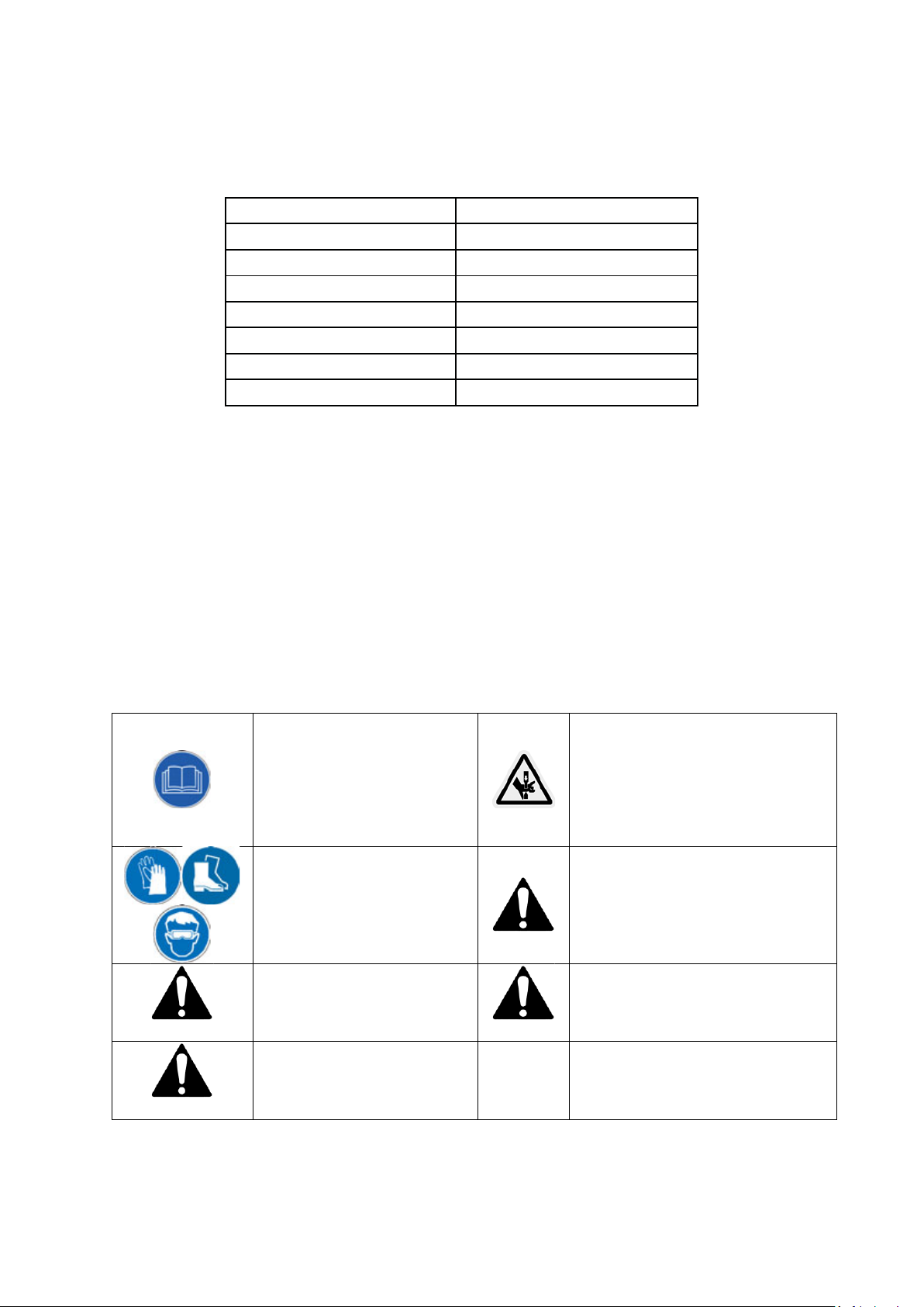
SAFETY SYMBOLS
Read & understand the
operator’s manual for the trailer
Risk of Slicing.
moving parts.
result in serious injury.
result in property damage.
DANGER
CAUTION
and the ride on product used to
pull the trailer before using the
machine. Failure to follow
instructions could result in death
or serious injury.
Wear gloves to protect your
hands. Wear foot protection at
all times. Wear eye protection to
protect against flying objects.
Indicates an imminently
hazardous situation which, if not
avoided, will result in serious
injury.
Indicates a potentially hazardous
situation which, if not avoided,
may result in minor or moderate
injury.
WARNING
CAUTION
Keep hands out of the way of all
Safety alert symbol. Used to alert you
to potential personal injury hazards.
Obey all safety messages that follow
this symbol to avoid possible injury.
Indicates a potentially hazardous
situation which, if not avoided, could
Used without the safety alert symbol
indicates a potentially hazardous
situation which, if not avoided, may
Page 5

IMPORTANT SAFETY WARNINGS
TO REDUCE RISK OF INJURY: Before any use be sure everyone using this product reads and understands all
safety instructions and other information contained in this manual.
GENERAL SAFETY
STAY ALERT
Do not operate the machine while under the influence of drugs, alcohol, or any medication that could affect
your ability to use it properly. Do not use this machine when you are tired or distracted from the job at hand.
Be aware of what you are doing at all times. Use common sense.
USERS
Do not at any time carry passengers sit or stand on the machine. Do not allow children to play on, stand upon
or climb in the machine. Never allow children or people unfamiliar with these instructions to use the machine.
Local regulations can restrict the age of the operator.
AVOID DANGEROUS CONDITIONS
Work in daylight or in good artificial light; always be sure of your footing on slopes; walk, never run with the
machine; exercise extreme caution when changing direction on slopes; do not work on excessively steep
slopes; use extreme caution when reversing or pulling the machine towards you; do not put hands or feet near
or under rotating or moving parts.
KEEP BYSTANDERS AND CHILDREN AWAY
Keep unauthorised persons a safe distance away from the machine. If approached, stop the machine
immediately. Do not allow children to handle, climb on or use the machine. Keep in mind the operator or user
is responsible for accidents or hazards occurring to other people or their property.
INSPECT YOUR MACHINE
Check all bolts, nuts, and screws for tightness before each use, especially those securing guards and drive
mechanisms. Vibration during use, may cause these to loosen.
Form a habit of checking to see that all other tools/equipment are removed from the working area before
turning it on. Replace damaged, missing or failed parts before using it. Warning labels carry important
information. Replace any missing or damaged warning labels.
DRESS PROPERLY
Do not wear loose clothing, gloves, scarfs, neckties or jewellery (rings, wrist watches), which can be caught in
moving parts. Always wear long trousers. Always wear substantial non slip, substantial or heavy-duty safety
footwear are highly recommended when working. Never operate barefoot or when wearing sandals. Wear a
face or dust mask if the operation is dusty. Always wear safety glasses/goggles and/or face shields. Everyday
eyeglasses have only impact resistant lenses; they are not safety glasses/goggles. Wear protective hair
covering to contain long hair, preventing it from getting caught in machinery.
DO NOT OVERREACH
Keep proper footing and balance at all times when using the machine. Use on slopes with great care. Never
stand on the machine. Serious injury could occur if the machine is tipped or if the moving parts are
unintentionally contacted. Do not store anything above or near the machine, where anyone might stand on
the machine to reach them.
AVOID INJURY FROM UNEXPECTED ACCIDENT
Keep hands & feet out of the way of all moving parts. Do not place any part of your body or any tool e.g. in the
machine during operation.
DO NOT FORCE TOOL
Always work within the rated capacity. Do not use machine for a purpose for which it was not intended. Be
careful when operating on steep grades (hill) the machine may tip over. Always operate at reduce speed in
rough terrain, along creeks, ditches and on hillsides. Do not operate close to creeks, ditches and public
highways. To avoid personal injury and/or equipment damage DO NOT EXCEED 10 MPH. Always use caution
when loading and unloading the machine. Only tow with recommended vehicles (Lawn/Garden Tractors and
ATVs). Always secure and lock dump machine to the vehicle hitch before operating.
NEVER LEAVE MACHINE RUNNING UNATTENDED
Do not leave the machine unattended until it has come to a complete stop.
INSPECT
Before using, always visually inspect to see that the tools are not worn or damaged. Replace worn or damaged
elements and bolts in sets, to preserve balance.
Page 6
1 4 3
2
MAINTAIN YOUR MACHINE WITH CARE
Clean the machine immediately after use. Keep the machine clean to ensure it operates to it’s full and safest
performance. When maintaining this machine, only the manufacturer’s original replacement parts should be
used. The use of non-original manufacturer parts may invalidate your warranty.
PROTECT THE ENVIRONMENT
Take left over materials to an authorised collection point or follow the stipulations in the country where the
machine is used. Do not discharge into drains, soil or water.
STORE IDLE EQUIPMENT
When not in use, the machine should be stored in a dry location. Keep the machine away from children and
others not qualified to use it. Keep away from direct sunlight.
WARNING
The warnings, cautions, and instructions outlined in this instruction manual cannot cover all possible
conditions or situations that may occur. It must be understood by the operator that common sense and
caution are factors which cannot be built into this product and must be supplied by the operator.
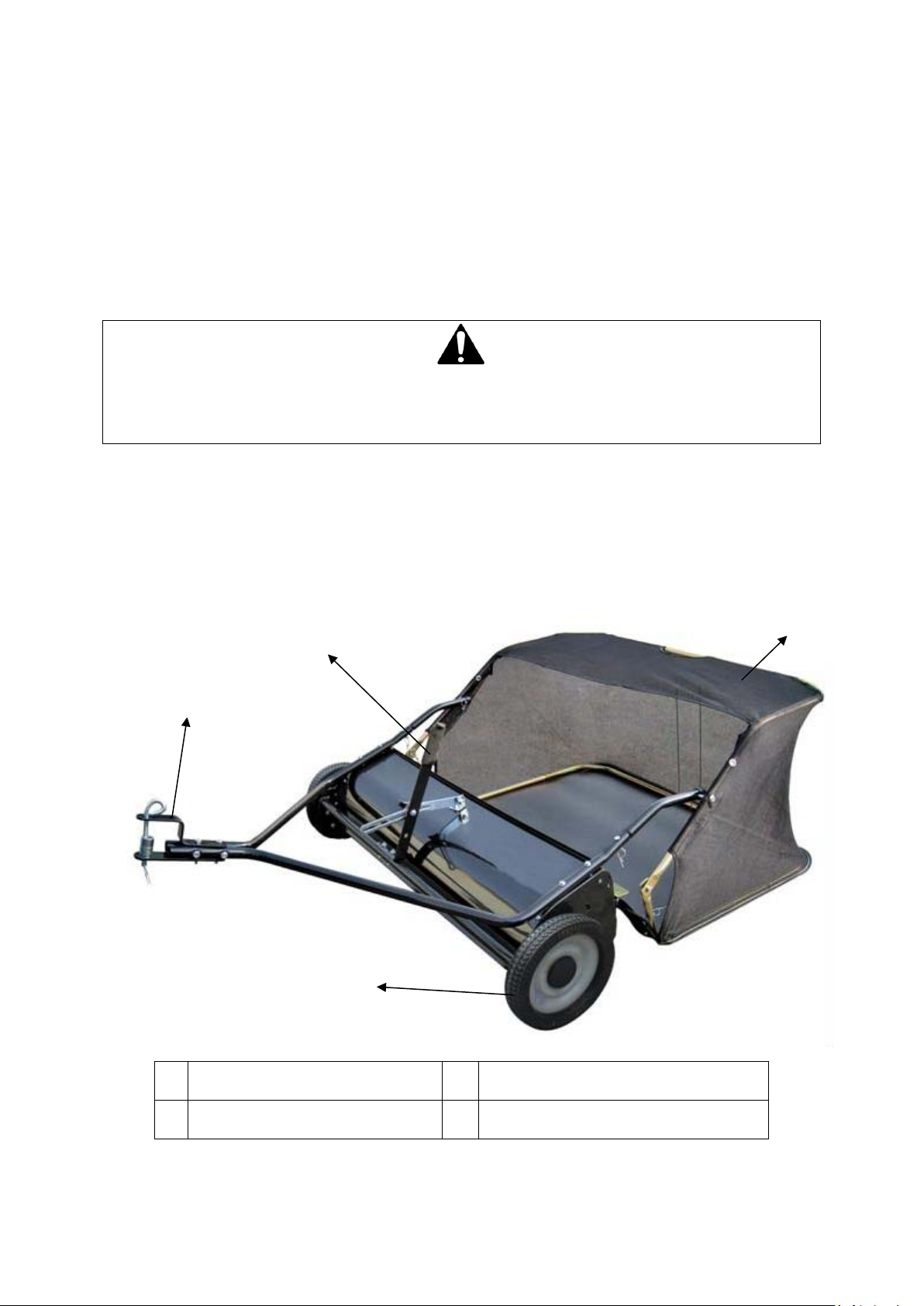
ABOUT YOUR LAWN SWEEPER
This heavy-duty tow-behind lawn sweeper makes work a breeze. The steel and nylon construction are durable
and lightweight, making it wear and rust-resistant, easy to tow, and easy to clean. The extra-large sweeping
span makes jobs easy and saves time when cleaning different types of debris, from grass clippings, twigs, and
leaves, to paper and much more. The tow-behind sweeper features a one-handed lever to adjust the brush
height. It can be stored in a shed or garage with minimal space. The large hopper makes loading and unloading
fast and convenient.
1.
2.
Hand Lever
Adjust the brush height
Nylon Hopper/Collector
Holds debris
3.
4.
Semi-pneumatic all-terrain tyres
Pin style; use only with approved vehicles.
Tyres
Hitch
Page 7
COMPONENTS
This product must be assembled correctly before use. Carefully remove the product and any accessories from
the carton. Inspect the product carefully to make sure there are no breakages or damage occurred during
shipping. Do not discard the packing material and carton until you have carefully inspected and satisfactorily
operated the product.
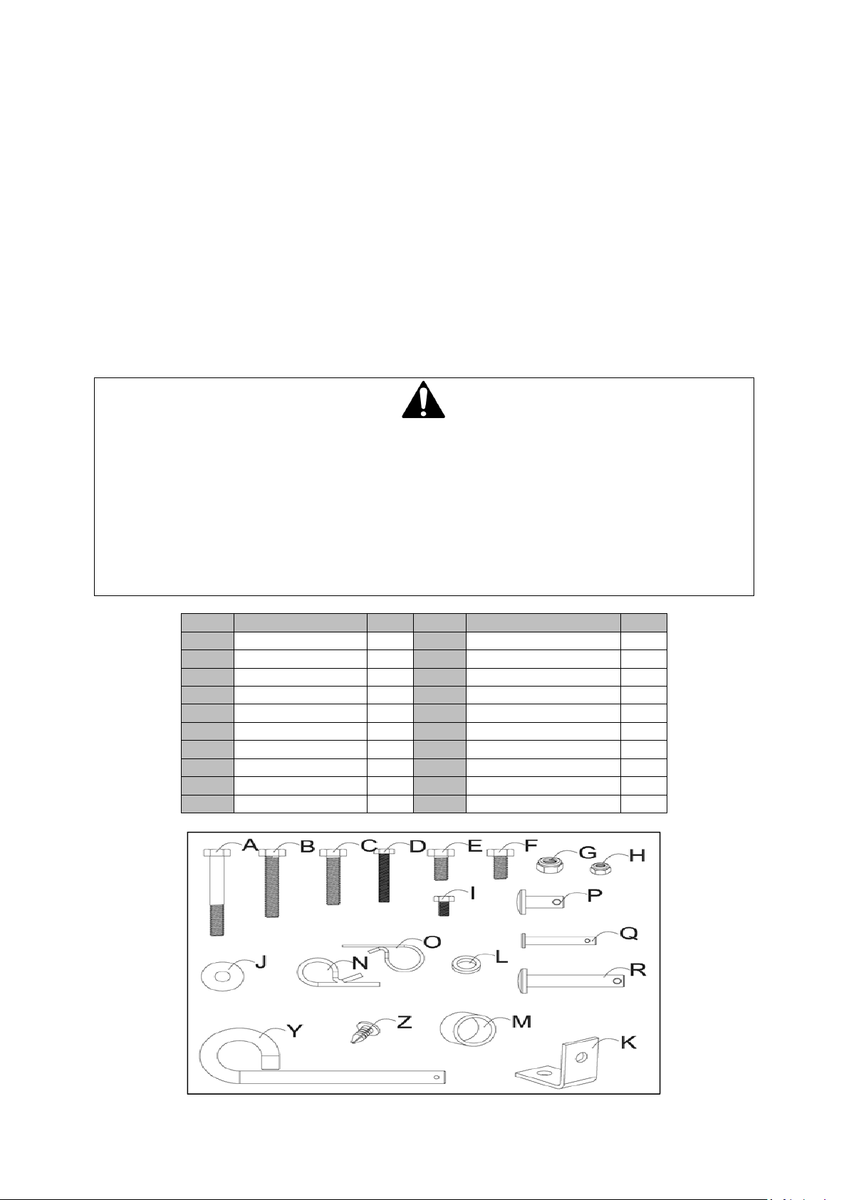
Take all parts out of the shipping crate and inspect components to ensure there are no missing pieces before
starting to assemble the lawn sweeper.
TOOLS REQUIRED
10mm, 13mm & 14mm Wrenches
1x Pliers
If you require assistance with regards to the contents or operation of the machine, please contact us:
TEL: 01793 333212
EMAIL: [email protected]
(MON – FRI 8.00AM TO 5.30PM EXCL. BANK HOLIDAYS)
WARNING
If any parts are damaged or missing do not operate this product until the parts are replaced. Failure to heed
this warning could result in serious personal injury.
Do not attempt to modify this product or create accessories not recommended for use with this product.
Any such alteration or modification is misuse and could result in a hazardous condition leading to possible
serious personal injury.
Read and follow all instructions for assembly and operation. Failure to properly assemble this equipment
could result in serious injury to the user or bystanders, or cause equipment damage.
ITEM DESCRIPTION QTY ITEM DESCRIPTION QTY
A Hex Bolt M8x65 2 K Angle Bracket 1
B Hex Bolt M8x50 2 L Adjustable Pole Spacer 1
C Hex Bolt M8x40 2 M Hitch Spacer 2
D Hex Bolt M6x40 4 N R Pin Ø3 5
E Hex Bolt M8x20 1 O R Pin Ø2 4
F Hex Bolt M8x16 1 P Clevis Pin Ø9.5x25 2
G Nylon Lock Nut M8 8 Q Clevis Pin Ø6x37 4
H Nylon Lock Nut M6 6 R Clevis Pin Ø8x59.5 2
I Hex Bolt M6x12 2 Y Hitch Pin 1
J Big Flat Washer Ø8 1 Z Plastic Plug 4
Page 8
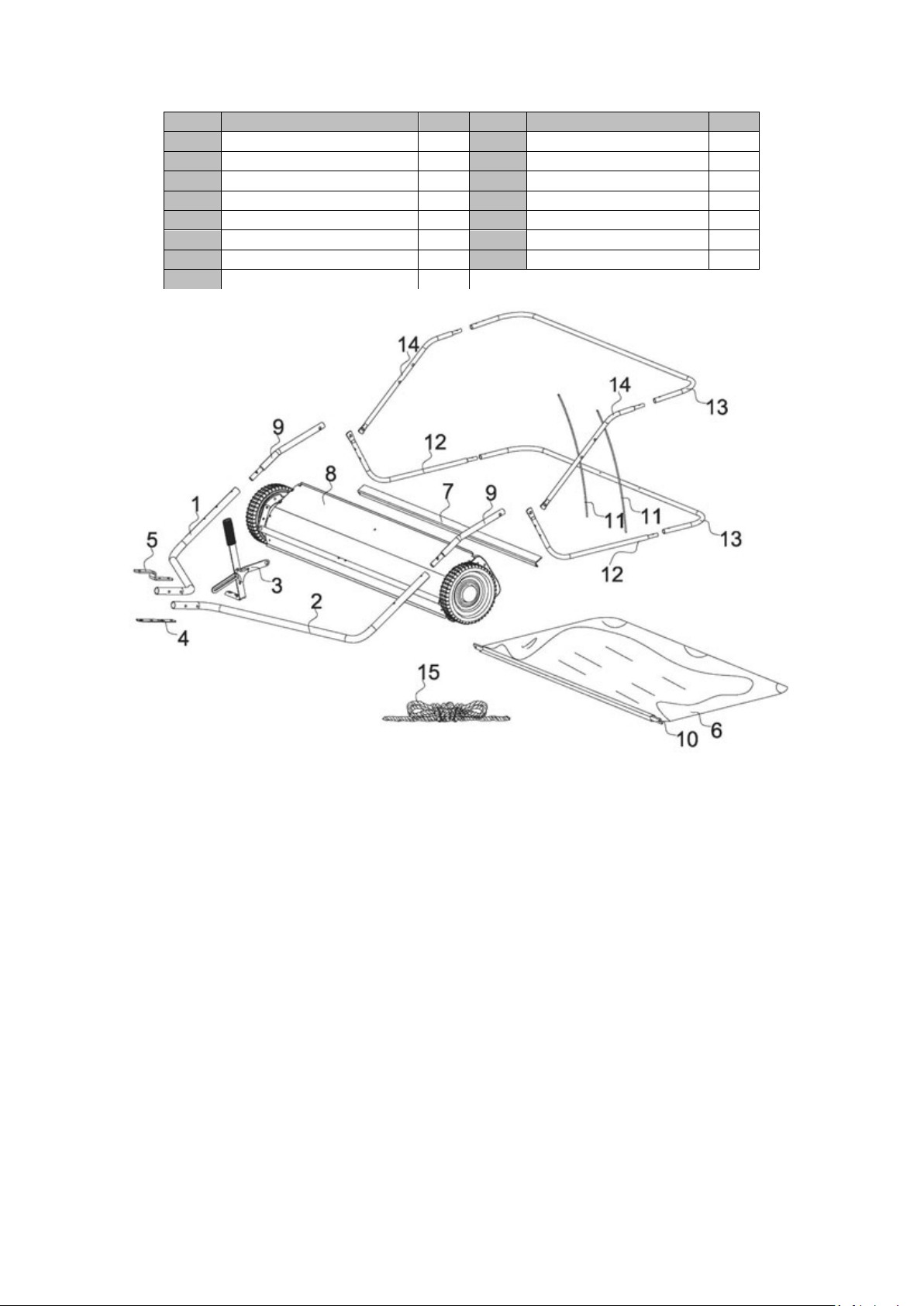
ITEM
DESCRIPTION
QTY
ITEM
DESCRIPTION
QTY 1 Hitch Tube (RH)
1 9 Bag Arm Tube
1 2 Hitch Tube (LH)
1
10
Bag Frame Strap
1 3 Handle Assembly
1
11
Hopper Support Rod
2 4 Hitch Bracket (Straight)
1
12
Lower Hopper Side Tube
2 5 Hitch Bracket
1
13
Rear Hopper Tube
2 6 Hopper Bag
1
14
Upper Hopper Side Tube
2 7 Connecting Rod
1
15
Rope
1 8 Sweeper Housing Assembly
2
Page 9
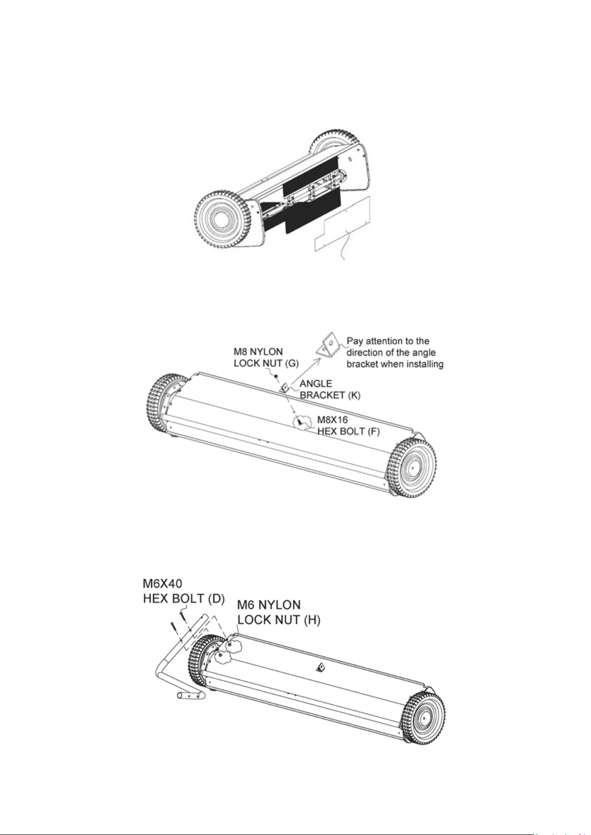
ASSEMBLY
Before assembling the lawn sweeper, lay out all of the parts and hardware as shown on the previous pages.
STEP 1 - MOUNT ANGLE BRACKET
Remove the three splints from the brushes.
THREE SPLINTS, USED TO PROTECT BRUSHES IN TRANSPORT
Attach the Angle Bracket (K) to the sweeper housing by using the Hex Bolt M8x16 (F) and the Nylon Lock Nut
M8 (G). Tighten securely.
NOTE: Right Hand (RH) and Left Hand (LH) refer to the drivers’ orientation when operating the vehicle.
STEP 2 - ATTACH HITCH TUBES
Attach the right-hand (RH) and left-hand (LH) hitch tubes (parts 1 and 2) to the sweeper housing assembly
(part 6) using Hex Bolts M6x40 (D) and Nylon Lock Nuts M6 (H). Tighten loosely.
Page 10
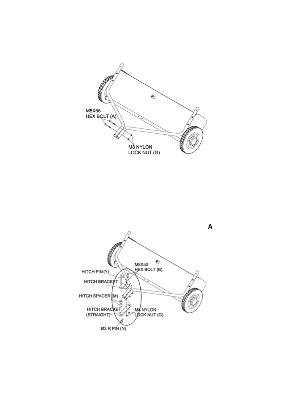
STEP 3 -
Once the Hitch tubes are attached, pass two Hex Bolts M8x75 (A) through the hitch-end (away from the
sweeper body) of the tubes to connect them together using two Nylon Lock Nuts M8 (G). Tighten loosely.
STEP 4 - MOUNT HITCH ASSEMBLY TO HITCH TUBES
NOTE: If your vehicle’s tow hitch is between 8” and 10”, mount the angled hitch bracket on the bottom of the
Attach the Hitch assembly in the following order: (see figure A)
• Mount the angled hitch bracket on top of the hitch tubes, with the straight hitch bracket on the bottom.
• Pass two hex bolts M8x50 (B) through the angled hitch bracket, premade notches in the hitch tubes,
• Finally, pass the Hitch Pin (Y) through angled hitch bracket, Hitch Spacer (M), and straight hitch bracket,
SECURE HITCH TUBES TOGETHER
hitch tubes for best performance (See Figure B). For vehicles 11” and higher, see Figure A.
straight hitch bracket, and tighten loosely with two nuts M8 (G).
and fasten with R Pin Ø3 (N).
Page 11
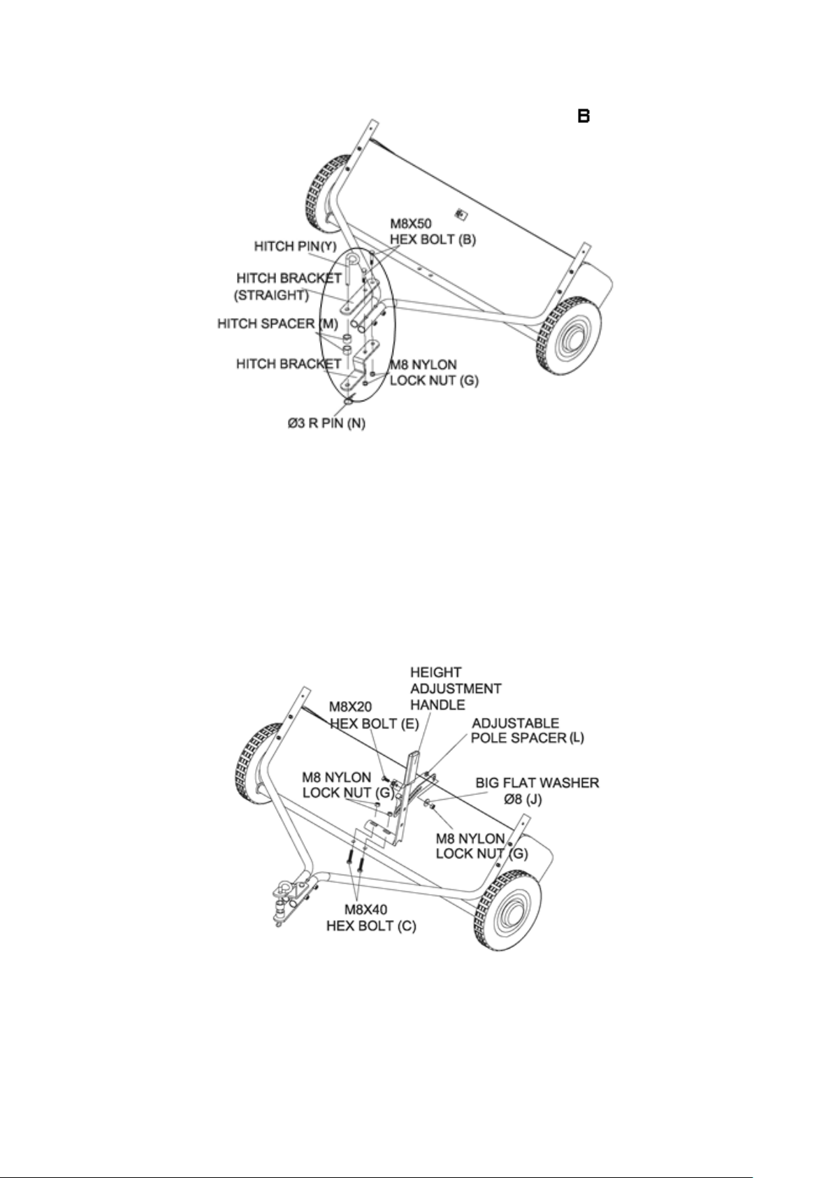
STEP 5 - SECURE
Tighten all nuts and bolts from Steps 2 thought 4.
STEP 6 - ATTACH HEIGHT ADJUSTMENT HANDLE
• Mount the height adjustment handle onto the height adjustment bar. (The height adjustment bar is
located outside of the sweeper housing assembly, spanning the wheels.) Use two Hex Bolts M8x40 (C) and
Nylon Lock Nuts M8 (G) to firmly attach the handle assembly to the bar.
• Attach the height adjustment strap to the angle bracket (mounted in Step 1). Align the round hole in the
height adjustment strap with the angle bracket. In the following order, pass Hex Bolt M8x20 (E) through
the angle bracket, the adjustable pole spacer (spacer bushing), the height adjustment strap, and the Big
Flat Washer Ø8 (J). Tighten securely with Nylon Lock Nut M8 (G).
Page 12
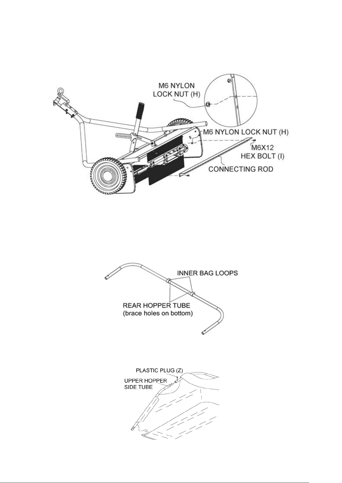
STEP 7 -
Mount the connecting rod using two Hex Bolts M6x12 (I) and Nylon Lock Nut M6 (H) to the upper most
mounting holes of the sweeper housing. Tighten securely.
STEP 8 - ASSEMBLE HOPPER BAG
• Unroll the hopper bag and place on the ground with the nylon fabric facing up and the heavy-duty nylon
• Inspect the first rear hopper tube (part 15) and locate the brace holes. Pass the tube through the six
•
MOUNT THE CONNECTING ROD TO THE SWEEPER HOUSING
floor facing the ground.
sewn-in bag loops at the top of the inside of the hopper bag with the brace holes facing downward.
• Pass the upper hopper side tubes through the stitched sleeves on either side of the nylon fabric. On each
side, insert the upper hopper side tube into the rear hopper tube, oriented downwards, and fasten plastic
plugs (Z).
Page 13
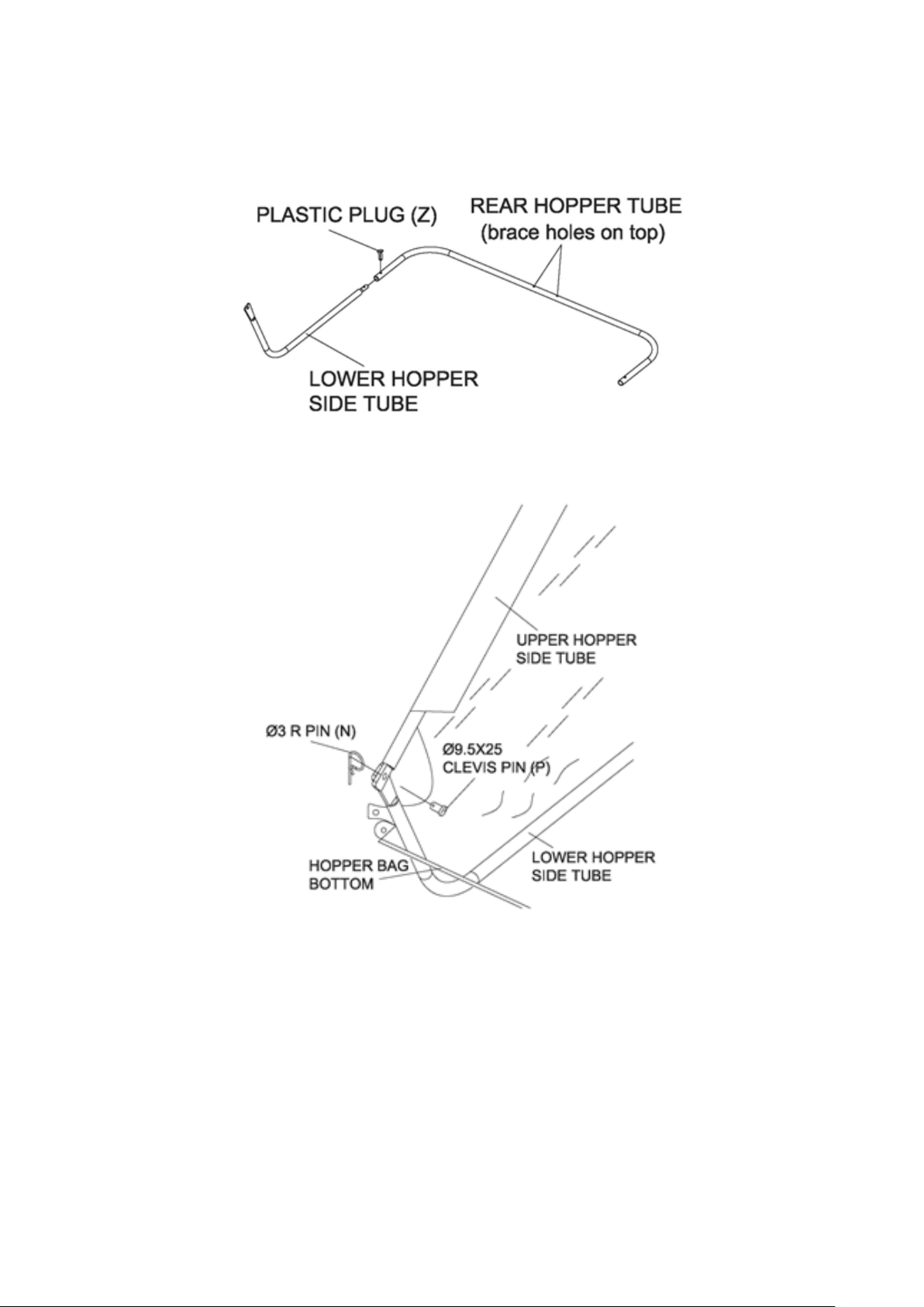
• Place the second rear hopper tube on the heavy-duty nylon floor of the hopper, with the brace holes
facing upward.
• On each side, insert the lower hopper side tubes, oriented upwards, into the (lower) rear hopper tube,
and fasten with plastic plugs (Z).
• On either side, align the ends of the upper and lower hopper side tubes and fasten these together with
Clevis Pin Ø9.5x25 (P). Secure with R Pin Ø3 (N).
• Locate the stitched sleeve at the front edge of the bag floor. Insert the bag frame strap into the sleeve. (In
some models, the bag frame strap is already inserted into the sleeve.)
Page 14
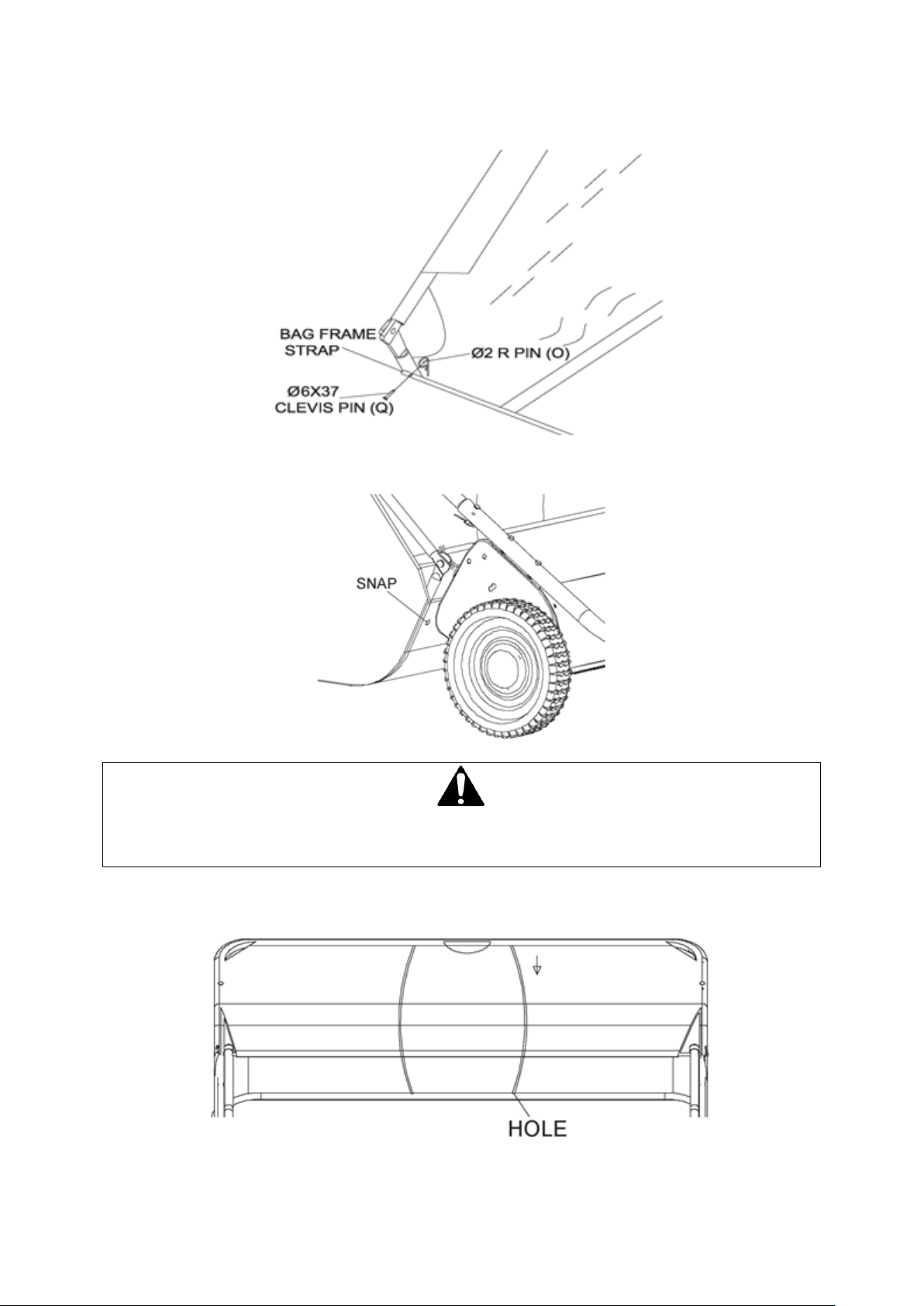
• Once inserted, mount the bag frame strap onto the lower hopper side tubes using Clevis Pins Ø6X37 (Q).
Secure with R Pin Ø2 (O).
• Locate the snap buttons on the nylon fabric. Snap them into the rivets on the heavy-duty nylon floor of
the hopper.
CAUTION
Do not over-stress (bend) the support rods while installing. Over stressing causes the rods to bend and lose
supporting tension.
• Insert the two hopper support rods into the brace holes in the upper and lower rear hopper tubes (part
15). The hopper assembly is now complete.
Page 15
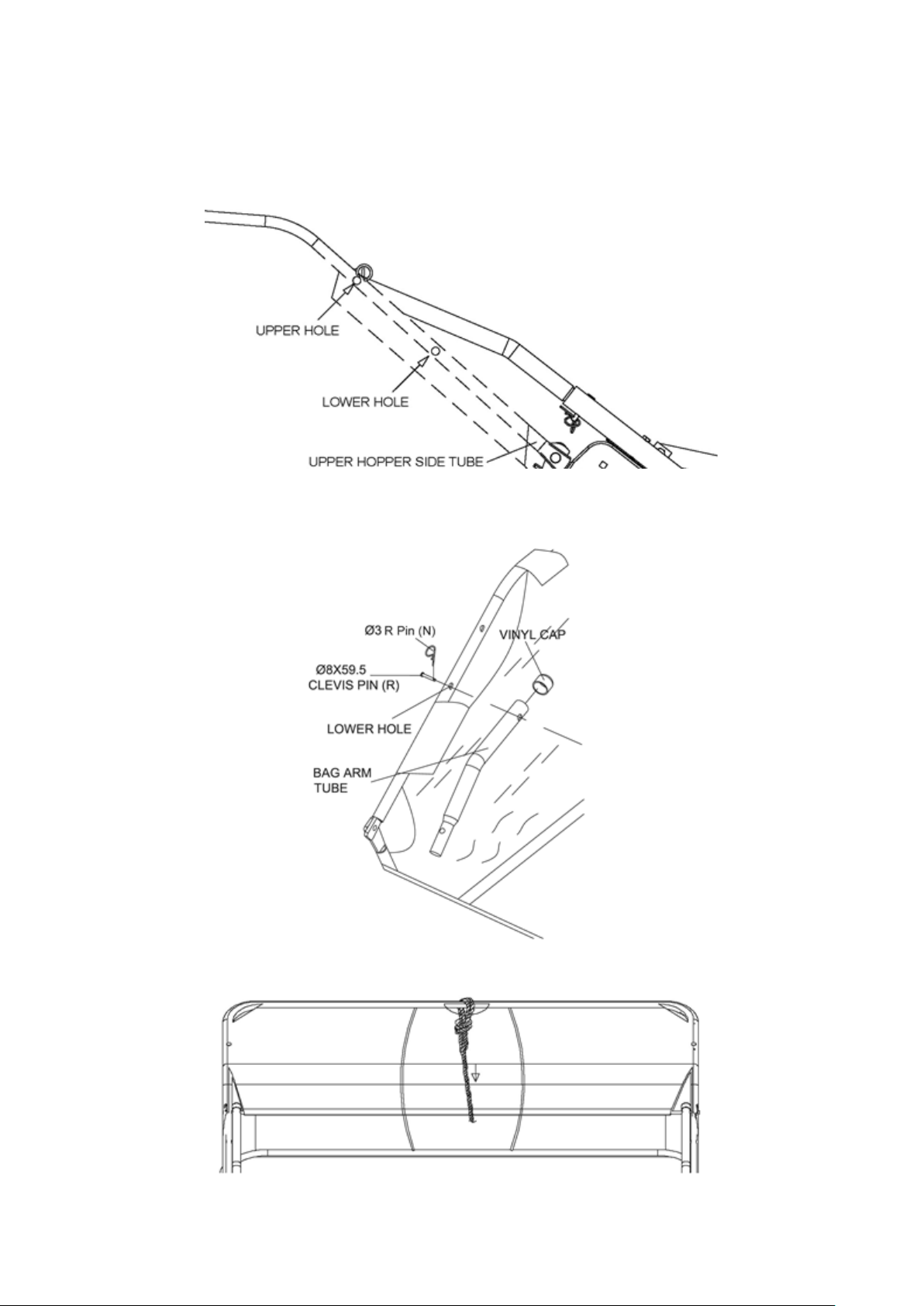
STEP 9 - ATTACH HOPPER BAG TO SWEEPER
• There are two holes in the bar of each of the upper hopper side tubes. Locate the lower hole and pierce
the nylon fabric at the location of the lower hole. Note: some models have rivets in the fabric and do not
require piercing the fabric.
• On each side, mount a bag arm tube onto the upper hopper side tube using clevis pin Ø8X59.5 (R). Secure
with R Pin Ø3 (N). Note the orientation of the bag arm tube: cap upward, male end facing down.
• Tie the rope to the upper hopper tube at the center of the bag frame.
Page 16
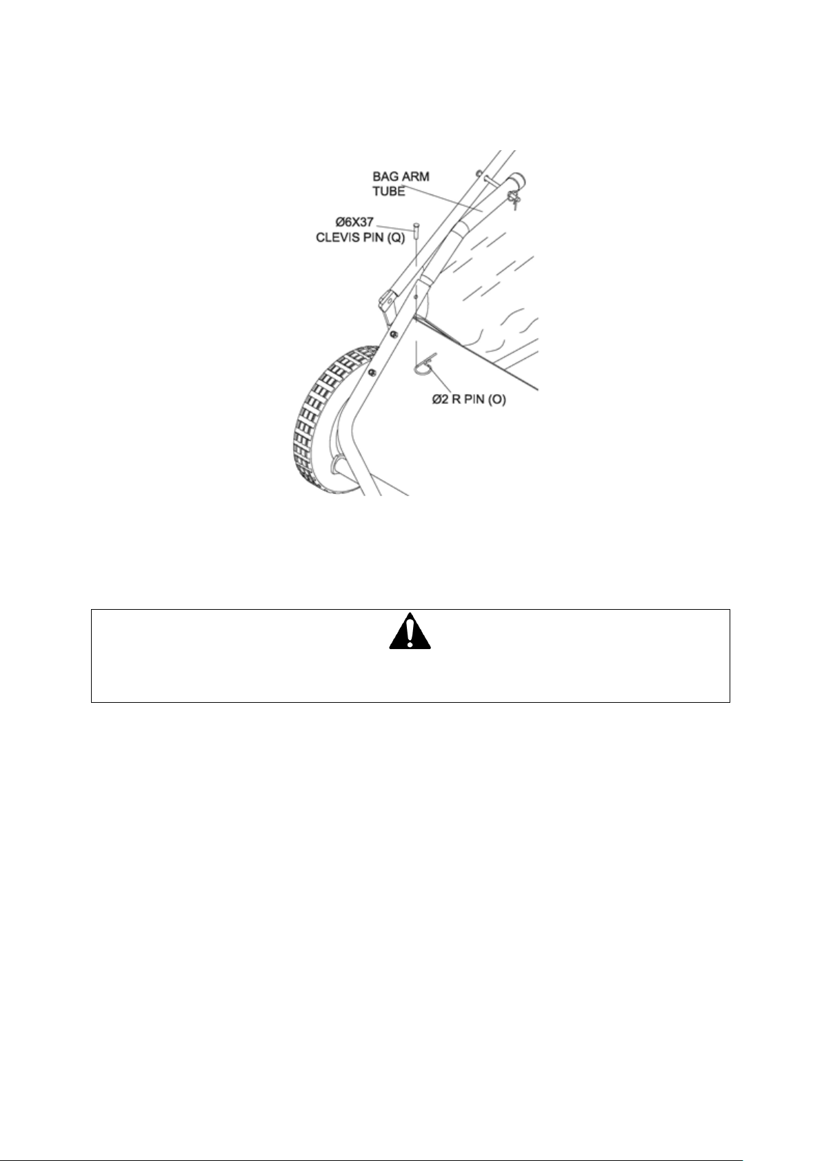
• Insert the male ends of the bag arm tubes into the hitch tubes at the back of the sweeper housing
assembly (away from the hitch). Secure using Clevis Pins Ø6X37 (Q) and R Pin Ø2 (O).
• Remove brush protection boards from inside of sweeper housing assembly.
• Check to see that all bolts are tightened adequately, and all pins are mounted securely. If all the
components are securely in place, the sweeper is completely assembled and ready for use.
OPERATION
WARNING
Before using the lawn sweeper, review the instructions below and safety information. Failure to follow
these instructions may result in property damage or injury to the operator or bystanders.
USING YOUR LAWN SWEEPER
Exercise caution at all times when using power equipment.
• Read this owner’s manual carefully for operating and service instructions before attempting to assemble
or operate this equipment. Be thoroughly familiar with the proper use of this equipment.
• Read the vehicle owner’s manual and vehicle safety rules, and know how to operate the vehicle before
using this equipment.
• Never allow children to operate the tractor or lawn sweeper attachment, and do not allow adults to
operate without proper instructions.
• Always handle with care (wear gloves) and wear substantial footwear when operating this lawn sweeper.
• Do not allow anyone to ride or sit on lawn sweeper attachment frame or on towing vehicle.
• Keep the area of operation clear of all persons, particularly small children and also pets.
• Always begin with the transmission in first (low) gear and engine at low speed, and gradually increase
speed as conditions permit.
• The vehicle braking and stability may be affected with the attachment of this equipment. Be aware of
changing conditions on slopes. Refer to safety rules in the vehicle owner's manual concerning safe
operation on slopes. STAY OFF OF STEEP SLOPES.
• Do not exceed 5MPH
• Always operate up and down a slope, never across the face of a slope.
• Always use caution when loading and unloading the hopper.
• Only tow with recommended vehicles (Lawn/Garden Tractors and ATVs).
Page 17
• Always refer to the vehicle owner’s manual for proper towing.
• Sweeper is not designed to be used with zero-turn mowers.
• Always secure and lock sweeper to the vehicle hitch before operating.
• This equipment should be operated at reduced speed on rough terrain, along creeks and ditches and on
hillsides, to prevent tipping and loss of control. Do not drive too close to a creek or a ditch.
• Do not tow this equipment on a highway or any other public thoroughfare.
• Follow the maintenance instructions as outlined in this owner’s manual.
ATTACH THE SWEEPER TO THE TOWING VEHICLE
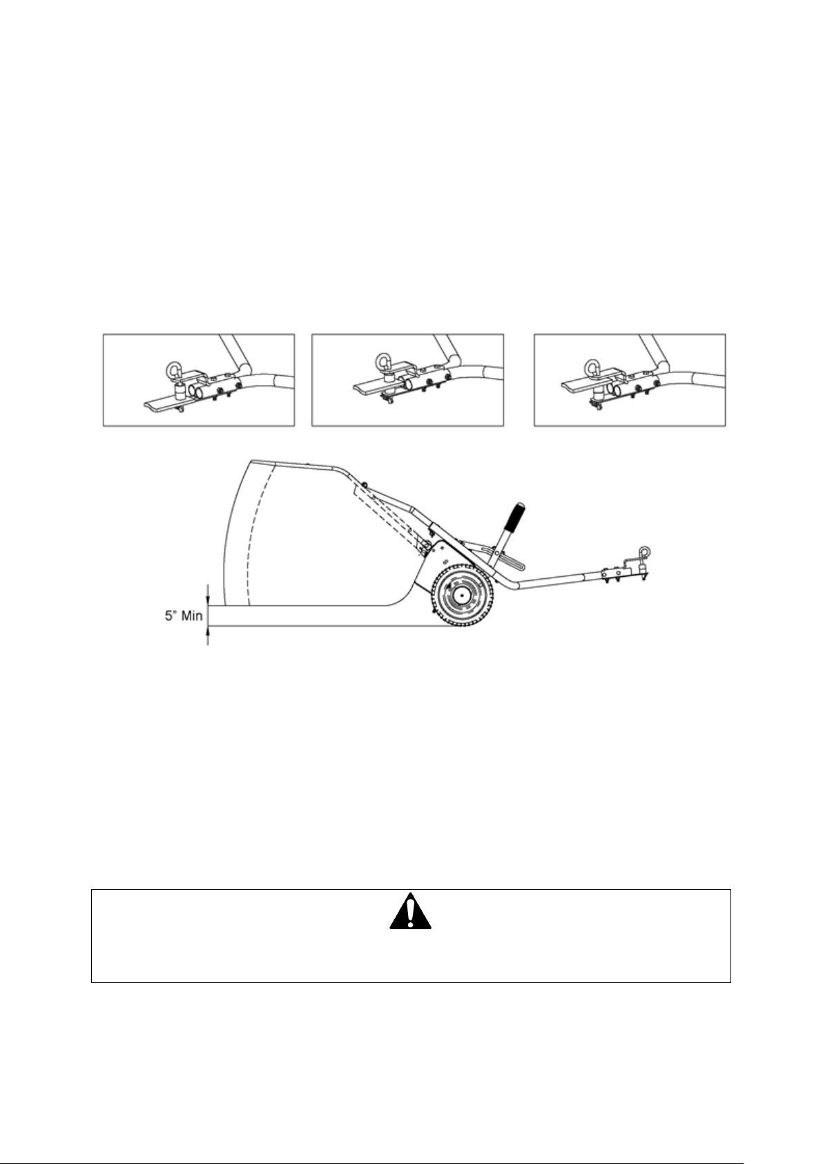
On a level surface, line up the towing vehicle with the sweeper. Use the hitch pin and spacers to adjust the
height of the tow hitch, as shown in the diagram. Once adjusted, insert the R Pin Ø3 to secure the hitch pin.
For best results, the hopper should be level with the ground at a minimum clearance of 5”. Secure the rope to
the tow vehicle.
ADJUST THE HEIGHT OF THE BRUSHES
Use the height adjustment handle to set the height of the brushes. For optimal results, the brush height should
be ½” below the tips of the grass. For sweeping other materials, you may need to adjust the height of the
brushes.
TOWING THE SWEEPER
Your sweeper is designed to work at speeds of 5mph and lower. You may damage the device or experience
sub-optimal results if exceeding 5mph. Your sweeper will work best on flat, smooth surfaces. If operating on a
slope, always tow the sweeper up or down the surface of the hill, not sideways along the slope.
DUMPING THE HOPPER
When dumping the hopper, use the rope to pull the basket forward. Dump the hopper regularly for best
performance.
CAUTION
Always keep body parts clear from and clothing detached from the sweeper and rope.
Keep sweeper away from fire or excessive heat will cause damage to the brushes and bag.
Page 18
MAINTENANCE
WARNING
Improper maintenance and storage of the trailer may void your warranty.
• After each use clean material out of hopper.
• Rinse/dry inside and outside of the sweeper after each use.
• Periodically check all fasteners for tightness and replace any damaged fasteners.
• Check brushes for debris and keep brushes and brush shaft clean for optimal performance.
• Twice a year apply a few drops of light multipurpose oil to the brush shaft bearings.
• Annually clean and lightly lubricate all moving parts.
• Every two years remove and clean gears and apply an even coat of light synthetic grease.
• Use a glossy enamel spray paint to touch up scratched or worn painted metal surfaces.
• Never exceed the hopper load capacity rating it will damage the bag.
• Regularly grease axle and wheel bearing area or when needed.
IMPORTANT:
If a part needs replacement, only use parts that meet the manufacturer’s specifications. Replacement parts
that do not meet specifications may result in a safety hazard or poor operation.
LUBRICATION
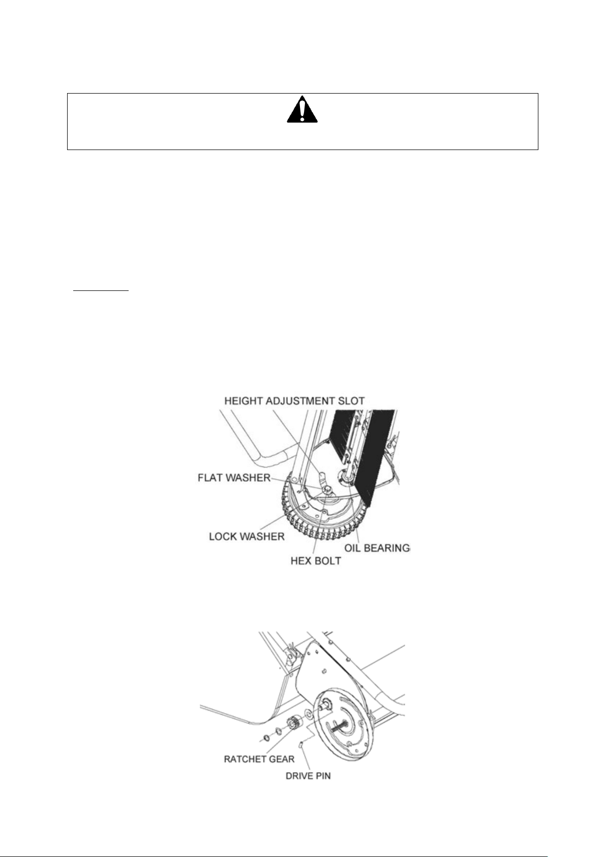
The bearings in the sweeper have been pre-lubricated at the factory; however, it is recommended that a few
drops of light multipurpose oil should be added to the brush shaft bearings twice a year. Also, every two years
the wheels should be removed to clean the gears. After cleaning the gears, apply an even coat of light
synthetic grease.
WHEEL GEARS/PAWL SERVICE
NOTE: To remove wheel, use a screwdriver to pop off hub cap, remove the lock nut and washer.
DO NOT remove both wheels at the same time. Remove one wheel at a time to prevent mixing parts or using
the wrong parts as the left and right wheels and parts are different. When removing gears, carefully note the
position of all washers and other parts.
Page 19
BRUSH REPLACEMENT
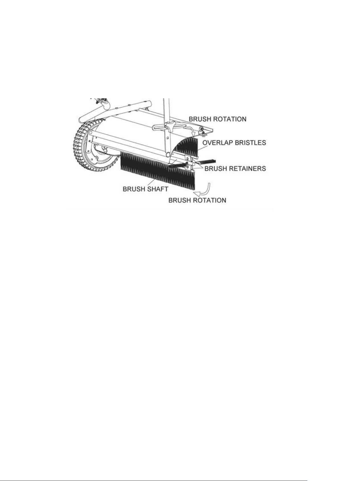
• Remove the hopper bag from lawn sweeper.
• Only replace one brush at a time.
• Tip the sweeper forward on housing. Do not remove the hex bolts from double brush retainers.
• Loosen hex bolts and hex lock nuts from single brush retainers. Slide brush out of retainers, making note
of over-lap bristles position.
• Install new brush, make sure the over-lap bristles are in the same position as before replacement.
STORAGE
• Be sure to completely empty, clean and dry the sweeper hopper bag before storage.
• Failure to properly clean the sweeper and hopper may cause deterioration such as rust or mold.
• Lightly lubricate all sweeper surfaces and moving parts to protect components and prevent rust.
• Store indoors or in a protected area during severe weather and winter months.
• Sweeper can be stored compactly:
o Pull the two bag arm tubes (#9) out of hitch tubes (#1 & #2).
o Remove the two hopper support rods (#11).
o Don’t allow the brushes to contact the ground during storage to prevent damage.
Page 20
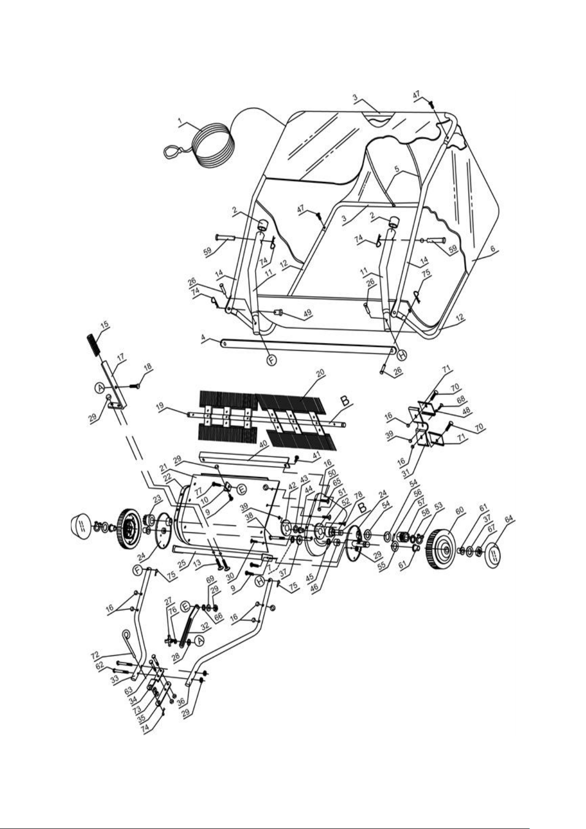
PARTS DIAGRAM – THTLS42 (1938210001)
NOTE: Parts Lists are
supplied for information
purposes only, not all
parts are stocked
individually & we
recommend you contact
our Spares Team on
01793 333212 for expert
.
advice
Page 21

ITEM
HANDY PART NO.
DESCRIPTION
QTY 1 TH181-1
Hopper Rope
1 2 TH181-2
Vinyl Cap
2
3
TH252-
Hopper Frame Tube (Rear)
2
4
TH252-N28000015
Bag Frame Strap
1 5 TH181-5
Hopper Support Rod
2 6 TH252-N28000039
Hopper Bag
1
7
TH252-GB93/10/DX
Lock Washer Ø10
2
9
TH181-9
Hex Bolt M8x16
5
10
TH181-10
Angle Bracket
1
11
TH181-11
Bag Arm Tube
2
12
TH252-28000006CD
Lower Hopper Frame Tube
2
13
TH181-13
Hex Bolt M8x40
2
14
TH252-
Upper Hopper Frame Tube
2
15
TH181-15
Height Adjust Grip
1
16
TH181-16
Nylon Lock Nut M6
18
17
TH181-17
Height Adjustment Handle
1
18
TH181-18
Carriage Bolt M8x30
1
19
TH252-
Brush Shaft
1
20
TH252-N28031000
Brush
4
21
TH252-N28000013
Wrapper
1
22
TH181-22
End Plate (R.H.)
1
23
TH181-23
Pinion Gear (R.H.)
1
24
TH181-24
Dust Cover Assembly
2
25
TH252-N28040000
Height Adjustment Assy
1
26
TH181-26
Clevis Pin Ø6x37
4
27
TH181-27
Wing Knob
1
28
TH121-28
External teeth Washer
1
29
TH181-29
Nylon Lock Nut M8
12
30
TH181-30
Slotted Pan Head Screw
6
31
TH181-31
Retainer Brush
6
32
TH181-32
Height Adjustment Strap
1
33
TH252-N280-00023
Hitch Tube (R.H)
1
34
TH181-34GM
Hitch Bracket
1
35
TH181-35GM
Hitch Bracket (Straight)
1
36
TH252-N28000022
Hitch Tube (L.H.)
1
37
TH181-37
Big Flat Washer Ø10
4
38
TH181-38
Hex Bolt M10x85
2
39
TH181-39
Nylon Lock Nut M5
20
PARTS LIST – THTD48 (1938212001) PART 1
Page 22

ITEM
HANDY PART NO.
DESCRIPTION
QTY
40
TH252-
Connecting Rod
1
41
TH181-41
Hex Bolt M6x12
2
42
TH181-42
Dust Cover Retainer
2
43
TH181-43
Inside Star Washer
2
44
TH181-44
Brush Shaft Bushing
2
45
TH181-45
Spacer Bushing
2
46
TH181-46
Spacer for Axle
2
47
TH181-47
Plastic Bolt
4
48
TH181-48
Star Washer Ø5
6
49
TH181-49
Clevis Pin C
2
50
TH181-50
End Plate (L.H.)
1
51
TH181-51
Special Washer
2
52
TH181-52
Bushing
2
53
TH181-53
Retaining Ring Ø15
2
54
TH181-54
Adj. Washer A
4
55
TH181-55
Adj. Washer C
2
56
TH252-940106020
Dowel Pin (Drive)
2
57
TH181-57
Pinion Gear (L.H.)
1
58
TH181-58
Adj. Washer B
2
59
TH181-59
Clevis Pin D
2
60
TH252-N28020000
Wheel & Tire Assembly
2
61
TH181-61
Wheel Bushing
4
62
TH181-62
Hex Bolt M8x65
2
63
TH181-63
Hex Bolt M8x50
2
64
TH181-64
Hub Cap
2
65
TH181-65
Hex Bolt M6x40
4
66
TH181-66
Heigh Adj. Strap Sapcer
1
67
TH181-67
Nylon Lock Nut M10
2
68
TH181-68
Hex Bolt M5x25
6
69
TH181-69
Big Flat Washer Ø8
1
70
TH181-70
Hex Bolt M6x20
12
71
TH181-71
Retainer Brush
12
72
TH181-72
Hitch Pin
1
73
TH181-73
Cotter Bushing
2
74
TH181-74
R Pin Ø3
5
75
TH181-75
R Pin Ø2
4
76
TH181-76
Big Flat Washer
1
77
TH181-77
Hex Bolt M8×20
1
78
TH252-M5X16
Slotted Pan Head Screw
8
PARTS LIST – THTD48 (1938212001) PART 2
Page 23

GJ HANDY & CO LTD USER WARRANTY POLICY
Users Statement of Warranty
Each new machine is warranted against defective material or assembly of material under normal usage. The
warranty applies to the original purchaser and covers faulty parts and the labour involved in replacing and
repairing those parts, which are of original manufacture.
Period of Warranty
Webb (excludes Electric Handheld, Dynamic, Heritage, Legacy), Webb Pro, Sanli Engine
a) 2 years from the original date of sale to the first domestic user.
b) 90 days from the original date of sale to the professional/commercial user.
c) 90 days from the original date of sale when used for hire.
d) A reduced warranty period of 90 days applies to those items which are subject to normal wear and
tear (e.g. but not limited to wheels, tyres, cutter bars, cylinders, cutting blades, blade boss, belts,
cables, nylon line & spool, collection bags, spark plugs).
e) Engines are supplied with a separate warranty to the machine. The engine manufacturers warranty
statement which will be supplied within the engine instruction manual. All enquiries and warranty
repairs should be discussed with the engine manufacturer or approved warranty repair dealer.
f) 90 days from the original date of purchase for Replacement Spare Parts (unless normal wear & tear
component, which are covered for 30 days).
g) All machines’ must be serviced within the first 12 months from the original date of purchase to
comply with the warranty, failure to do so will invalidate the 2nd year of the warranty.
Webb Electric Handheld, Webb Dynamic, Heritage & Legacy, Handy, Mowerland, Q-Garden
a) 1 year from the original date of sale to the first domestic user.
b) 90 days from the original date of sale to the professional/commercial user.
c) 90 days from the original date of sale when used for hire.
d) A reduced warranty period of 90 days applies to those items which are subject to normal wear and
tear (e.g. but not limited to wheels, tyres, cutter bars, cylinders, cutting blades, blade boss, belts,
cables, nylon line & spool, collection bags, spark plugs).
e) Engines are supplied with a separate warranty to the machine. The engine manufacturers warranty
statement which will be supplied within the engine instruction manual. All enquiries and warranty
repairs should be discussed with the engine manufacturer or approved warranty repair dealer.
f) 90 days from the original date of purchase for Replacement Spare Parts (unless normal wear & tear
component, which are covered for 30 days).
All warranty repairs must be undertaken by an authorised service dealer. These dealers have been accredited
by GJ Handy & Co Ltd and agree to only use genuine parts and follow our repair procedures.
Not covered by this warranty
a) The warranty policy does not cover any depreciation or damages caused by ordinary wear, rusting or
corrosion, lack of correct maintenance or operation, misuse, abuse, lack of transportation or accident.
b) The warranty policy does not cover any costs necessary for the standard periodic maintenance
services instructed by the operator’s manual, or service parts replacement which would include oil,
filters, tyres, belts, brake linings, fuses, blades, seals and other service parts unless it can be proven
that the item has evidence of faulty manufacture.
c) The warranty policy will not cover failure or damage caused as a result of parts or accessories being
modified without the written approval of GJ Handy & Co Ltd.
d) The warranty policy will not cover the unit if non-genuine parts have been fitted and as a result
damage has occurred to the unit.
e) The warranty policy is non-transferable and is only applicable to the original purchaser.
Page 24

Disclaimer
a) This warranty is only a remedy for defect of products. GJ Handy & Co Ltd will never warranty in terms
of the merchantability or the fitness for a particular purpose.
b) No person is authorised to make any warranties, representations or promises, expressed or implied,
on behalf of GJ Handy & Co Ltd, or to modify the terms conditions or limitation of this warranty policy
in any way.
c) Neither GJ Handy & Co Ltd nor any company affiliated with GJ Handy & Co Ltd shall be liable in any
event or manner whatsoever for incidental or consequential damages or injuries, including, but not
limited to, loss of crops, loss of profit, out of pocket expenses or profits, rental of substitute
equipment or other commercial losses.
General
a) Most warrantable failures show up within the first few weeks of use. These failures are usually
straightforward and warranty assessment is relatively easy.
b) Failures relating to cutter decks and belts need careful investigation, as the cause may not always be
straightforward. Look for damage to blades and pulleys especially when the cutter belt or blade boss
have snapped or cracked as this could be due to impact damage.
c) Customers should always refer to the operator/instruction manual when any disputed problem arises,
you will find most areas covered within the manual.
Page 25

EC DECLARATION OF CONFORMITY
We Handy Distribution Ltd - SN3 5HY (Importer) declare that the product:
Designation: 42” (107cm) Towed Lawn Sweeper
Model(s): THTLS42
Product Number: 1938210001
Type/Serial No: As per rating label on machine
Working Width: 42” (107cm)
Complies with the following directives:
2006/42/EC – Machinery Directive
The conformity assessment procedure followed was in accordance with
EN ISO 12100:2010,
EN 349:1993+A1:2008,
EN 93:1997+A1:2009,
EN ISO 13857:2008
Notified Bodies:
ENTE CERTIFICAZIONE MACCHINE
Address(es):
Via Ca’ Bella, 243 - Loc. Castello id Serravalle - 40053 Valsamoggia (BO) - ITALY
Authorised signatory & technical file holder
Date:
21/05/2019
Signature:
Name:
Mr. Simon Belcher
Position:
Chairman
Company:
Handy Distribution Ltd
Address:
Murdock Rd, Dorcan, Swindon, Wiltshire, SN3 5HY.
Page 26

NOTES
Page 27

Page 28

For spares or support of your handy product,
please contact us:
Tel: 01793 333212
Email: [email protected]
(Mon – Fri 8.00am to 5.30pm excl. Bank Holidays)
To see our range of garden machinery & equipment visit:
www.thehandy.co.uk
Making gardening easier & affordable since 1938
Distributed by Handy Distribution, Murdock Road, Dorcan, Swindon, SN3 5HY
 Loading...