

Page 1

INSTRUCTION MANUAL
3000W ELECTRIC
VERTICAL
8-TON LOGSPLITTER
MODEL NO: THPLS8TE -- PRODUCT NO: 1938184001
EN - ORIGINAL INSTRUCTIONS
ASSEMBLY REQUIRED – TWO PERSON
SAVE THESE INSTRUCTIONS
SPARES & SUPPORT: 01793 333212
FOR YOUR SAFETY
Please read & understand this manual, paying attention to the safety instructions, before use.
Incorrect use of the product could put the operator or machine in danger.
Whilst every effort has been made to ensure the accuracy of information contained in this manual, our
policy of continuous improvement determines the right to make modifications without prior warning.
Images used are for illustration purposes only
20-09-2018
Page 2

Copyright Notice
Copyright © Handy Distribution
Permission is granted to reproduce this publication for personal & educational use only.
Commercial copying, redistribution, hiring or lending is prohibited.
No part of this publication may be stored in a retrieval system or transmitted in any other form or means without
written permission from Handy Distribution.
In all cases this copyright notice must remain intact.
Page 3

CONTENTS
SPECIFICATIONS
IMPORTANT INFORMATION
GENERAL SAFETY INSTRUCTIONS
SET UP & PREPARATION FOR OPERATION
KNOW YOUR MACHINE
OPERATION
CHECKING & REPLACING HYDRAULIC OIL
TROUBLE SHOOTING
MAINTENANCE & STORAGE
WIRING & HYDRAULIC SYSTEM DIAGRAMS
EC DECLARATION OF CONFORMITY
PARTS DIAGRAM & LIST
WARRANTY
ASSEMBLY IS REQUIRED – TWO PERSON
This product requires assembly before use. See the “Assembly” section for instructions.
Please check that all parts required for the assembly of this spreader are included. If for any reason you
believe a part for the assembly is missing or damaged, please contact us.
If you require any assistance with regards to the contents or operation of
your machine, please contact us:
TEL: 01793 333212
EMAIL: [email protected]
(MON – FRI 8.00AM TO 5.30PM EXCL. BANK HOLIDAYS)
SPECIAL WARNINGS & INSTRUCTIONS
• The splitting operation of the machine is designed to be activated by one person. While there is the
possibility that additional operators could be working with the machine (e.g. for loading and unloading),
only one operator should activate splitting operations;
• The machine shall not be used by children;
• Description of functional tests of the machine;
• The installation and maintenance requirements including a list of those devices e.g. two-hand control
device which should be verified, how frequently the verification shall be carried out and by what method;
• Do not remove jammed logs with your hands. Never use another person to help you with freeing jammed
logs. Push the wedge until the log is split open.
Page 4

Model Number
THPLS8TE
Product Number
1938184001
Motor*
(230V ~50Hz 13A) 3000W, S6 40%,
Splitting Force
8 Ton
Forward Speed
3.2 cm/s
Retract Speed
17.3 cm/s
Hydraulic Pressure
21.0 Mpa
Hydraulic Oil Tank Capacity
4.0L
Hydraulic Oil
Type 22
Stroke Length (mm)
485
Log Capacity Diameter (mm)**
Min 80 – 300 Max
Log Capacity Length (mm)
Min 100 – 550 Max
Overall Size (cm)
L 84.5, W 93.5, H 150
Weight (kg)
N.W 109.9 – G.W 117.0
Noise Pressure Level (LpA)
83.6 dbA under no load;
89.7 dbA under full load
Vibration
<2.5 m/s²
SPECIFICATIONS
The manufacturer reserves the right to change the product specification and livery according to continued
product improvements.
* S6 40%, continuous operation periodic duty: time of one load cycle is 10 minutes, operation time at
constant load is 4 minutes, operation time at no-load is 6 minutes.
** The diameter of the log is not the only factor that determines how easy it will be to split. A small log can
be difficult to split when it has knots or is a particularly hard wood.
IMPORTANT INFORMATION
HYDRAULIC OIL
This machine is supplied with Hydraulic oil from the factory, to allow the machine to be used straight from the carton
following assembly. Do check the oil level (instructions available in the manual) prior to the first use and periodically
thereafter. Type 22 hydraulic oil is recommended.
ELECTRICAL REQUIREMENTS
Connect the main leads to a standard 220-240V±10% (50Hz±1Hz) electrical supply which has protection devices of
under-voltage, over-voltage, over-current as well as a residual current device (RCD) which has a maximum residual
current rated at 0.03A.
EXTENSIONS LEADS
We do not recommend the use of extension leads with this product. The use of an extension lead can seriously reduce
the machines splitting capabilities.
WORKING CONDITIONS
This log splitter is a domestic use model. It is designed for operating under ambient temperatures between +5°C and
40°C and for installation at altitudes no more than 1000m above M.S.L. The surrounding humidity should be less than
50% at 40°C. It can be stored or transported under ambient temperatures between -25°C and 55°C.
INSPECT YOUR LOG
Make sure there are no nails or foreign objects in logs to be split. The ends of the logs must be cut square.
Branches must be cut off entirely so that the trunk is relatively smooth.
Page 5

GENERAL SAFETY INSTRUCTIONS
It is important that you read and understand the owner’s manual and labels affixed to the machine. Learn its
application and limitations as well as the specific potential hazards. Retain these instructions for future
reference. The operator is responsible for following the warnings & instructions in this manual and on the
product.
Read & understand operator’s
manual before using the
machine. Failure to follow
instructions could result in death
or serious injury.
Keep clear of all moving
DANGER
parts.
Wear protective gloves to
protect your hands
Whenever the machine is in use,
eye protection must be worn to
safeguard against flying objects.
Hearing protection must also be
used to protect users hearing.
Wear protective footwear
Check your log splitter before
turning it on. Keep guards in
place and in working order.
Replace damaged, missing or
failed parts before using it.
10m
Do not remove jammed
logs with your hands
Before making
adjustments, changing
parts, cleaning, or working
on the log splitter, always
disconnect the power.
Consult the technical
manual before servicing.
Dispose of all oil at an
authorised collection point
or follow the local
authority stipulations that
apply.
Dispose of used oil in an
environmentally friendly
way.
Keep all bystanders &
animals at least 10 metres
away from the machine
during operation.
If approached, stop the
machine immediately.
DANGER
CAUTION
Do not use in the rain.
Keep your work space tidy!
Untidiness may result in
accidents.
Indicates an imminently
hazardous situation which, if not
avoided, will result in serious
injury.
Indicates a potentially hazardous
situation which, if not avoided,
may result in minor or moderate
injury.
WARNING
CAUTION
Stay clear of moving parts.
Safety alert symbol. Used
that follow this symbol to
hazardous situation which,
if not avoided, could result
WARNING
to alert you to potential
personal injury hazards.
Obey all safety messages
avoid possible injury.
Indicates a potentially
in serious injury
Used without the safety
alert symbol indicates a
potentially hazardous
situation which, if not
avoided, may result in
property damage.
Page 6

STAY ALERT
Do not operate the machine while under the influence of drugs, alcohol, or any medication that could affect
your ability to use it properly. Do not use this machine when you are tired or distracted from the job at hand.
Be aware of what you are doing at all times. Use common sense.
AVOID DANGEROUS CONDITIONS
Always operate your log splitter on dry, solid, level ground. Never operate your log splitter on slippery, wet,
muddy, or icy surfaces. The location you choose should be free from any tall grass, brush, or other
interferences. There should be plenty of room for handling, and help the operator stay alert. Keep your work
area clean and well lighted. Cluttered areas invite injuries. To avoid tripping, do not leave tools, logs, or other
components laying around the work area. Do not use the log splitter in wet or damp areas or expose it to rain.
Do not use it in areas where fumes from paint, solvents or flammable liquids pose a potential hazard.
INSPECT YOUR MACHINE
Check your logsplitter before turning it on. Keep guards in place and in working order. Form a habit of checking
to see that keys and adjusting wrenches are removed from tool area before turning it on. Replace damaged,
missing or failed parts before using it.
DRESS PROPERLY
Do not wear loose clothing, gloves, neckties or jewellery (rings, wrist watches). They can be caught in moving
parts. Protective electrically nonconductive gloves and non-skid footwear are
recommended when working. Wear protective hair covering to contain long hair, preventing it from get caught
in machinery.
PROTECT EYES & FACE
Any logsplitter may throw foreign objects into the eyes. This can cause permanent eye damage. Always wear
safety goggles. Everyday eye-glasses have only impact resistant lenses. They are not safety glasses.
We do not recommend using the logsplitter on the ground for operation. This is an awkward operating
position, bringing the operators face close to the machine, and thus risking being struck by wood chips or
debris.
AVOID ELECTRICAL SHOCK
Check that the electric circuit is adequately protected and that it corresponds with the power, voltage and
frequency of the motor. Check that there is a ground connection and a regulation differential switch upstream.
Ground the logsplitter. Prevent body contact with grounded surfaces: pipes, radiators, ranges, and refrigerator
enclosures.
Never open the pushbutton box on the motor. Should this be necessary, contact a qualified electrician. Make
sure your fingers do not touch the plug's metal prongs when plugging or unplugging the logsplitter.
After installation, the degree of protection of the BSI and the SEV approved plug and socket combination shall
be IP44D at least. Avoid excessive bending and twisting of the connection between the power cord of the
British plug and the junction box.
KEEP BYSTANDERS AND CHILDREN AWAY
The logsplitter must be always operated by one person only. Other people should keep a safe distance from
the work area (10 metres recommended), especially when the logsplitter is under operation. Never use
another person to help you with freeing a jammed log.
INSPECT YOUR LOG
Make sure there are no nails or foreign objects in logs to be split. The ends of the logs must be cut square.
Branches must be cut flush with the trunk.
DO NOT OVERREACH
Operating floor must not be slippery. Always keep proper footing and balance. Never stand on the logsplitter.
Serious injury could occur if the tool is tipped or if the cutting tool is unintentionally contacted. Do not store
anything above or near the logsplitter where anyone might stand on the tool to reach them.
AVOID INJURY FROM UNEXPECTED ACCIDENT
Always pay full attention to the movement of the log-pusher. Do not attempt to load the log on until the logpusher has stopped. Keep hands out of the way of all moving parts.
PROTECT YOUR HANDS
Keep your hands away from splits and cracks which open in the log; They may close suddenly and crush or
amputate your hands. Do not remove jammed logs with your hands.
DO NOT FORCE TOOL
It will do a better and safer job at its design rate. Never try to split logs larger than those indicated in the
specifications table. This could be dangerous and may damage the machine. Don't use the logsplitter for a
purpose for which it was not intended.
Page 7

NEVER LEAVE MACHINE RUNNING UNATTENDED
Do not leave the machine unattended, until it has come to a complete stop and the power removed from the
electrical source.
DISCONNECT POWER
Unplug when not in use, before adjusting, changing parts, cleaning, or working on the logsplitter. All servicing
and repairs are recommended to be undertaken by an approved service dealer.
MAINTAIN YOUR MACHINE WITH CARE
Clean the machine immediately after use. Keep the machine clean to ensure it operates to its full & safest
performance. When maintaining this machine, only the manufacturer’s original replacement parts should be
used. The use of non-original manufacturer parts may invalidate your warranty.
PROTECT THE ENVIRONMENT
Take used oil to an authorised collection point or follow the stipulations in the country where the logsplitter
is used. Do not discharge into drains, soil or water.
STORE IDLE EQUIPMENT
When not in use, the machine should be stored in a dry location. Keep the machine away from children and
others not qualified to use it.
This symbol on the product or on its packaging indicates that this product may not be
treated as household waste. Instead it shall be handed over to the applicable collection
point for the recycling of electrical and electronic equipment.
For more detailed information about recycling of this product, please contact your local
council office, your household waste disposal service or shop where you purchased the
product.
UNPACKING
At least 2 people will be required to unpack the logsplitter. Take the following steps:
Page 8

SET UP & PREPARATION FOR OPERATION
Familiarise yourself with the assembly components of this logsplitter in the illustrations. If you believe you are
missing any components, please contact us:
1. Log Splitter Frame
2. Control Lever & Guard Assembly (1 pair)
3. Adjustable Log Holder (1 pair)
4. Wheels (1 pair)
5. Support Table
6. Operator's Manual
7. Hardware Bag (see contents below)
Page 9

ASSEMBLY
1. Pass the axle through the wheel from outside
and put on two washers as shown in the
following figure. Slide the axle into the two
holes on the base of log splitter and secure it
with another washer and R-pin from inside. Put
on the wheel cap. Insert the wheel shaft into
the mount bracket.
2. Repeat the same steps to mount the wheel on
the other side.
1. Before assembly, loosen the star knob by
turning it counterclockwise
2. Unfold the log support table, make the
three parts of it at the same surface level.
WHEELS
SUPPORT TABLE
Page 10

3. Insert the hooks of the log support table into
the mount brackets.
4. Tighten the star knob.
CONTROL LEVER
1. Pull Spring Pin (A) to remove the Lock Pin
(B).
2. Apply a thin coat of grease to both surfaces
of the Control Lever Guard as illustrated.
3. Insert the Control Lever and Guard Assy and
make sure the Control Lever End goes into
the slot of Connection Bracket (C).
4. Lock the Control Lever and Guard Assy.
down with the Lock Pin (B) and Spring Pin
(A).
5. Follow the same steps to install the other
Control Lever and Guard Assy on the other
side.
CHECK BOTH SIDES AFTER ASSEMBLY. THE
CONTROL LEVERS MUST BE PLACED IN THE
SLOTS OF THE CONNECTION BRACKETS.
Page 11
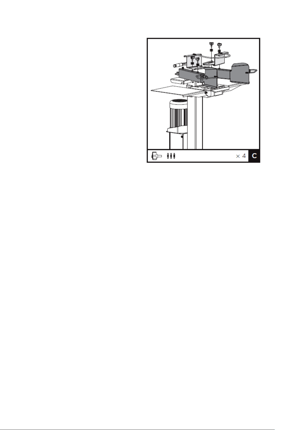
ADJUSTABLE LOG HOLDER
1. Secure the log clamps on the armguards
with star knobs and flat washers. Each star
knob with three flat washers.
Page 12

KNOW YOUR MACHINE
Make yourself aware of the compnents and operational levers of the machine, prior to attempting any work.
Page 13
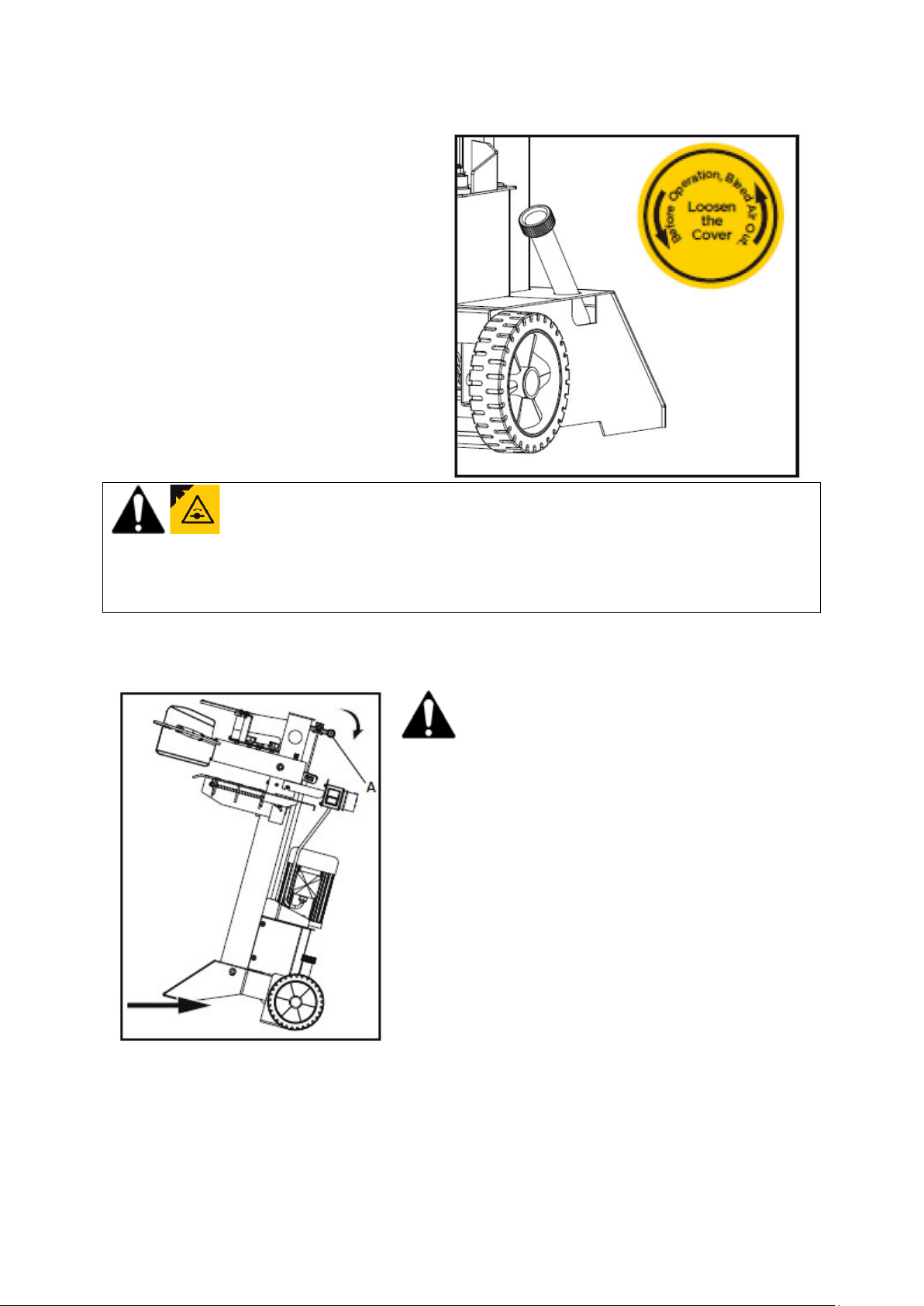
BLEED SCREW
IMPORTANT
Before operating the logsplitter, the Oil Filler/Air
Bleed should be loosened a few rotations until air
can go in and out of the oil tank smoothly. Air
flow through the Oil Filler/Air Bleed hole should
be noticeable while the logsplitter is working.
Before moving the log splitter, ensure the Oil
Filler/Air Bleed is tightened to avoid oil leaks.
FAILURE TO LOOSEN THE OIL FILLER/AIR BLEED WILL KEEP SEALED AIR IN THE HYDRAULIC SYSTEM
COMPRESSED. SUCH CONTINUOUS AIR COMPRESSION WILL BLOW OUT THE SEALS OF THE HYDRAULIC
SYSTEM AND CAN CAUSE PERMANENT DAMAGE TO THE LOGSPLITTER, WHICH IS NOT COVERED UNDER THE
TERMS & CONDITIONS OF THE MANUFACTURERS WARRANTY.
TRANSPORTING YOUR LOGSPLITTER
The logsplitter is equipped with 2 wheels for minor moving. To move the log splitter to the work site. Grip the
handle to tilt the log splitter slightly after making sure the oil tank cover is tightened.
DO NOT TRANSPORT THE LOGSPLITTER WITH WOOD LOADED
Page 14
OPERATION
APPLICATION CONDITIONS
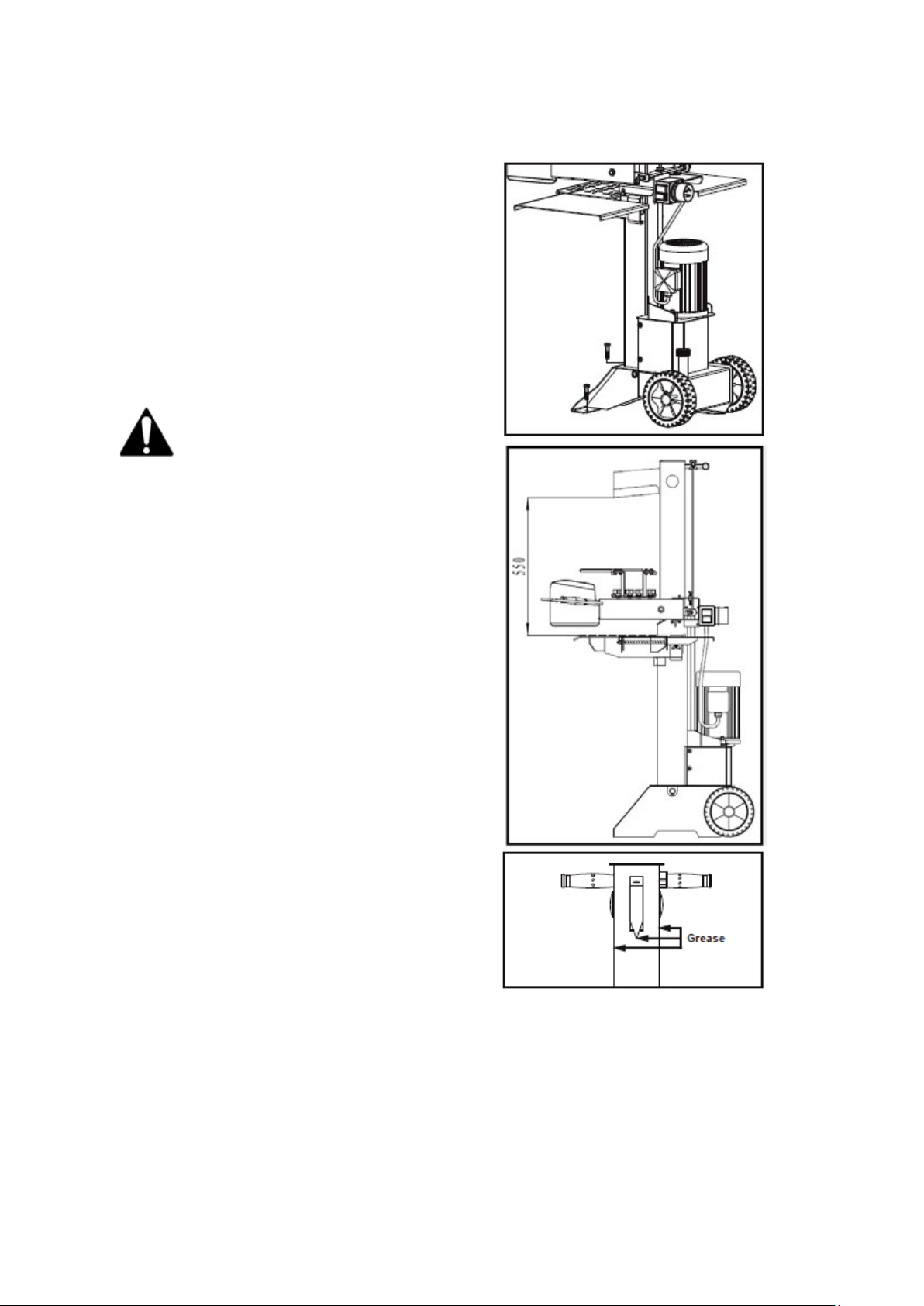
Before operation, we recommend the machine is
fixed to the machine using Bolts M10x30 (not
supplied) on level ground.
1. Plan your work site. Work safely and save effort
by planning your work beforehand. Have your
logs positioned where they can be easily
reached. Have a site located to stack the split
wood or load it onto a nearby truck or another
carrier.
2. Prepare the logs for splitting. This splitter
accommodates logs up to 105cm in length.
When cutting up limbs and large sections, do
not cut sections any longer than 105cm.
Do not attempt to split green logs. Dry, seasoned
logs split much more easily, and will not jam as
frequently as green wood.
3. To apply a thin coat of grease to the surfaces of
the ram before operation will lengthen the
durability of the ram.
4. Route the power cord. Route the cord from the
power source to the splitter in a way that
safeguards against tripping on the cord, or the
cord becoming damaged during the work
session. Protect the power cord from impacts,
pulling or corrosive materials.
5. Open the Oil Filler/Air Bleed. Loosen the oil tank
cover a few turns whenever the splitter being
used. Retighten this cover when you finished.
6. While operating under extremely low
temperature, keep the log splitter running
under no load for 15 minutes to preheat the
hydraulic oil.
7. Before initial operation, check to be sure the
two-handed operation is properly functioning
by following steps:
• Lower both control levers, splitting wedge
lowers to approx. 5cm above the take above the
highest table position.
• Release either of the levers, splitting wedge
should remain in the original position.
• Release both levers, the ram should rise to the
highest position automatically.
Page 15

8. To set wedge ram stroke, take the following
steps:
• Move splitting wedge to desired position. The
upper position of the ram wedge travel should
be about 3~5cm over the logs to be split.
• Release a control lever or switch off motor.
• Release the Setscrew (A) with L key. Raise
Adjusting Rod (B) until Adjusting Rod (B) is
started to be stopped by the spring inside.
Tighten the Setscrew (A).
• Release both control levers or switch on motor.
• Check upper position of splitting wedge.
Place log onto splitter. Place the log onto the
9.
support table vertically and sitting flat on the
support table. Be sure the wedge and support table
will contact the log squarely on the ends. Never
attempt to split a log at an angle.
Break log in the direction of its growing grain. Do not
place log across the log splitter for splitting. It may be
dangerous and may seriously damage the machine.
10. Adjust the Log Holders (A) according to the
11. Hold the log with clamping brackets closely in the
12. Stack as you work. This will provide a safer work
diameter of the log to obtain most comfortable
Control Levers angle.
control lever guards. lower levers to start the
splitting. Releasing either lever stops the motion of
the splitting wedge. Releasing both handles to
return the splitting wedge to the upper position.
area, by keeping it uncluttered, and avoid the
danger of tripping, or damaging the power cord.
Accumulated split wood and wood chips can create a
hazardous work environment. Never continue to work
in a cluttered work area which may cause you to slip,
trip or fall.
Never force the log splitter for more than 5 seconds. Do not keep pressure on it to split excessively hard
wood.
After 5 seconds of constant use, the oil under pressure will be overheated and the machine could be damaged.
For such extremely hard logs, rotate it by 90
should still be split with the grain as shown in the diagrams in this manual). In any case, if you are not able to
split the log, this means that its hardness exceeds the capacity of the machine and thus that log should be
discarded to protect the log splitter.
SHARPENING THE SPLITTING WEDGE
This log splitter is equipped with a reinforced splitting wedge which is specially treated. After long periods of
operation, and when required; sharpen the wedge using a fine-toothed file removing any burrs or flat spots on
the edge.
o
to see whether it can be split in a different direction (the log
Page 16

CHECKING & REPLACING HYDRAULIC OIL
CHECKING HYDRAULIC OIL LEVEL
Periodically check the oil level to ensure it is between the 2 grooves around the Oil Filler/Air Bleed. To check
the oil.
• Ensure the machine is upright, not operating or plugged into the electrical source.
• Unscrew the Oil Filler/air Bleed & remove it.
• If the oil level is lower than the minimum (min) bottom mark on the dipstick refill with Type 22 Hydraulic
oil and check the level again, until the oil level reaches the maximum (max) mark on the dipstick.
The following hydraulic oils or equivalent Type 22 are recommended for the log splitter’s hydraulic
transmission system:
o HANDY PARTS Logsplitter Oil WPL110 (1L), WPL113 (5L)
o SHELL Tellus 22
o MOBIL DTE 11
o ARAL Vitam GF 22
o BP Energol HLP-HM 22
• Clean the dipstick and put it back into the oil tank. Make sure it is tightened to avoid leaks during transit.
• Never exceed the maximum level. Empty oil if the maximum level is exceeded until the oil level is
between the minimum & maximum marks on the dipstick.
• The machine will operate as designed with oil in between the minimum & maximum marks.
Read dipstick to determine the maximum and minimum of the oil level. Low oil can damage the oil pump.
Overfilling can result in excessive temperature in the hydraulic transmission system.
Page 17
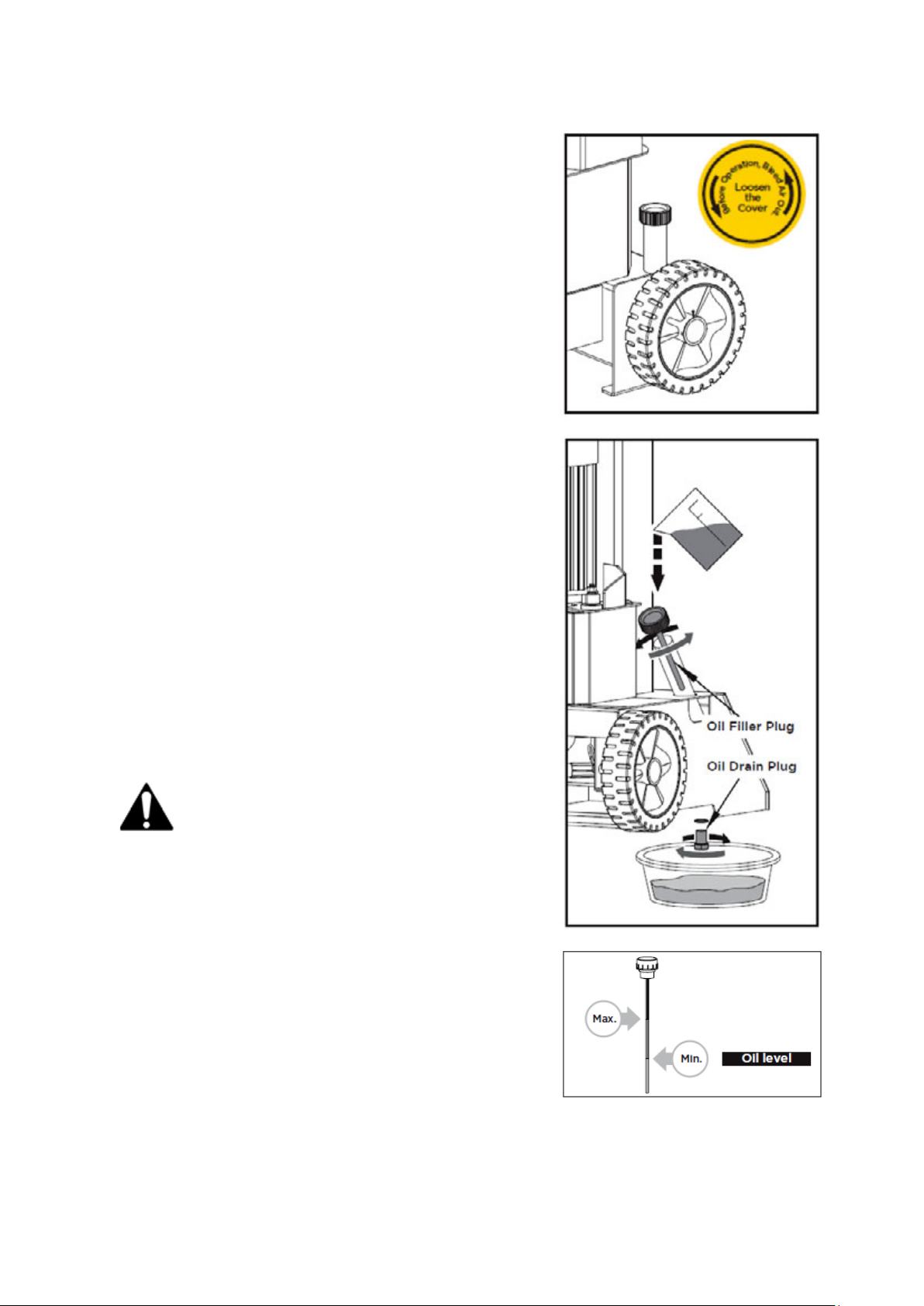
REPLACING HYDRAULIC OIL
The hydraulic system is a closed system with oil tank, oil pump and
control valve. Check oil level regularly with dipstick. Low oil levels
can damage the oil pump. Oil Level should measure approx. 1 ~ 2
cm lower than the upper surface of the oil tank.
The oil should be completely changed once a year.
• Make sure moving parts stops and the log splitter is unplugged
from the power source.
• Make sure that no dirt or debris finds its way into the oil tank
• Use a drain pan to aid in the removal of all used oil and
particles.
• Remove oil drain plug to drain oil from the hydraulic
transmission system. Examine oil for metal chips as a
precaution to future problems.
• Following an oil change, activate the log splitter a few times
without actually splitting with the Oil Filler/Air Bleed removed,
to disperse any trapped air in the hydraulic system.
The following hydraulic oils or equivalent Type 22 are
recommended for the log splitter’s hydraulic transmission
system:
o HANDY PARTS Logsplitter Oil WPL110 (1L), WPL113 (5L)
o SHELL Tellus 22
o MOBIL DTE 11
o ARAL Vitam GF 22
o BP Energol HLP-HM 22
• Clean the Dipstick and put it back into the oil tank.
• Never exceed the maximum level. Empty oil if the maximum
level is exceeded until the oil level is between the minimum &
maximum marks on the dipstick.
• The machine will operate as designed with oil in between the
minimum & maximum marks.
• Clean the dipstick before replacing it. Make sure it is
tightened to avoid leaks during transit.
Read dipstick to determine SHARPENING WEDGE the maximum
and minimum of the oil level. Low oil can damage the oil pump.
Overfilling can result in excessive temperature in the hydraulic
transmission system.
Page 18

TROUBLE SHOOTING
PROBLEM
PROBABLE CAUSE
REMEDY SUGGESTED
Fails to split logs
Log is improperly positioned
Refer to “Operation” section for perfect
log loading.
The sizes or hardness of the log
exceeds the capacity of the
machine
Reduce the log sizes before splitting it on
the log splitter.
Wedge cutting edge is blunt
Refer to “Sharpening Wedge” section to
sharpen the cutting edge.
Oil leaks
Locate leak(s) and contact the dealer.
The log pusher moves
jerkily, taking
Unfamiliar noise or
vibrating a lot
Lack of hydraulic oil and
excessive air in the hydraulic
system.
Check oil level for possible oil refilling.
Contact an approved service dealer.
Excessive air in the hydraulic
system.
Remove the Oil Filler/Air Bleed. Operate
the ram 5 or 6 times without a log in place.
Return the Oil Filler/Air Bleed and leave in
the open position and split the log. If the
problem continues contact the local
approved service dealer.
Oil leaks around
cylinder ram or from
other points
Air sealed in hydraulic system while
operating
Loosen Bleed Screw by 3 ~ 4 rotations
before operating the log splitter.
Oil Filler/Air Bleed is not tightened
before moving the log splitter.
Tighten the oil filler up before moving the
log splitter.
Hydraulic Control Valve
Assembly and / or seal(s) worn
Contact an approved service dealer.
Motor running, ram not
moving
Extension lead being used
Be sure the extension lead is no longer
than 10m and its cross-section is no less
than 2.5mm² to allow enough current flow
to the motor.
MAINTENANCE & STORAGE
Always ensure the Bleed Screw is fully tightened when the machine is not in use.
When not in use, the machine should be stored in a dry location. Keep the machine away from children and
others not qualified to use it. Avoid direct sunlight.
Do not store anything above or near the machine, where anyone might stand on the machine to reach them.
Page 19
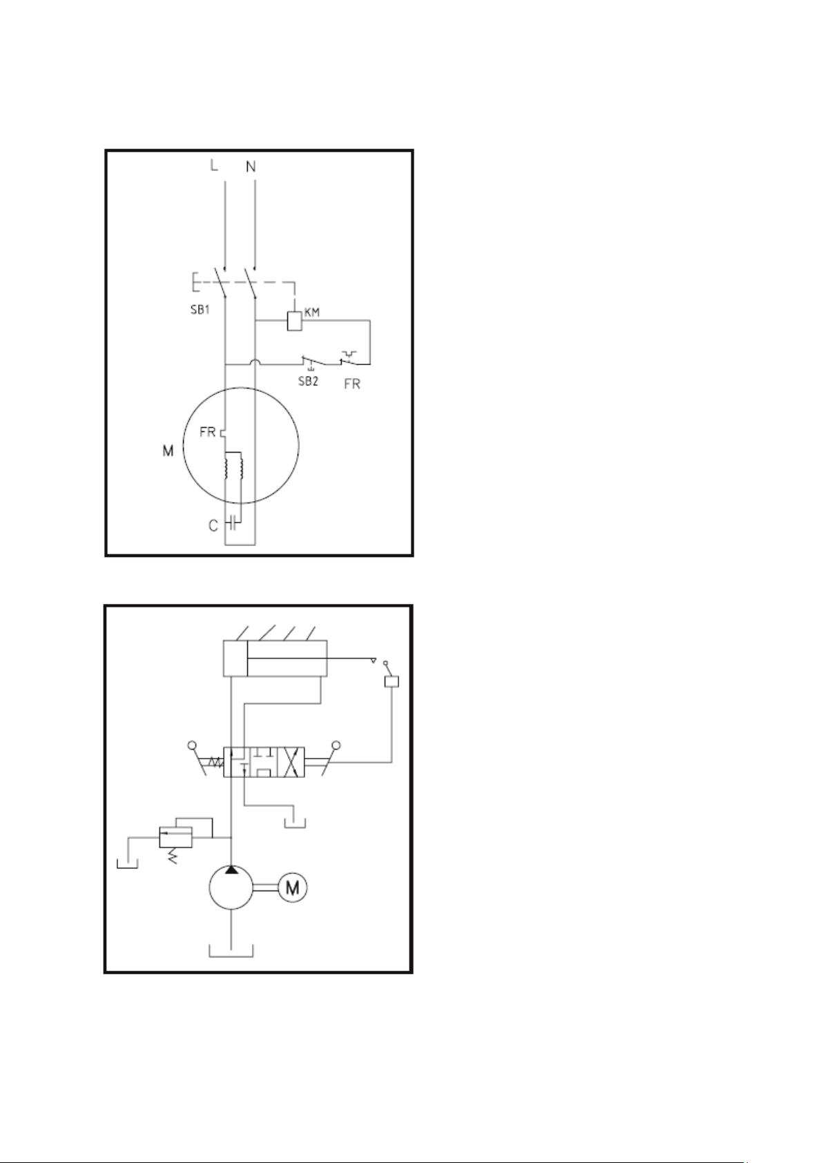
WIRING & HYDRAULIC SYSTEM DIAGRAMS
WIRING DIAGRAM
HYDRAULIC DIAGRAM
Page 20

EC DECLARATION OF CONFORMITY
We Handy Distribution Ltd - SN3 5HY (Importer) declare that the product:
Designation: Vertical Electric 8 Ton Log Splitter
Model(s): THPLS8TE
Product Number: 1938184001
Type/Serial No: As per rating label on machine
Motor Wattage: 3000
Complies with the following directives:
2006/42/EC – Machinery Directive
2014/30/EU – Electromagnetic Capability
The conformity assessment procedure followed was in accordance with
EN 609-1:2017, EN 60204-1:2006+A1 :2009+AC:2010
Notified Bodies:
TÜV Rheinland LGS Products GmbH
Address(es):
Tillystrabe 2 – 90431 Nürnberg
Authorised signatory & technical file holder
Date:
01/09/2018
Signature:
Name:
Mr. Simon Belcher
Position:
Chairman
Company:
Handy Distribution Ltd
Address:
Murdock Rd, Dorcan, Swindon, Wiltshire, SN3 5HY.
Page 21
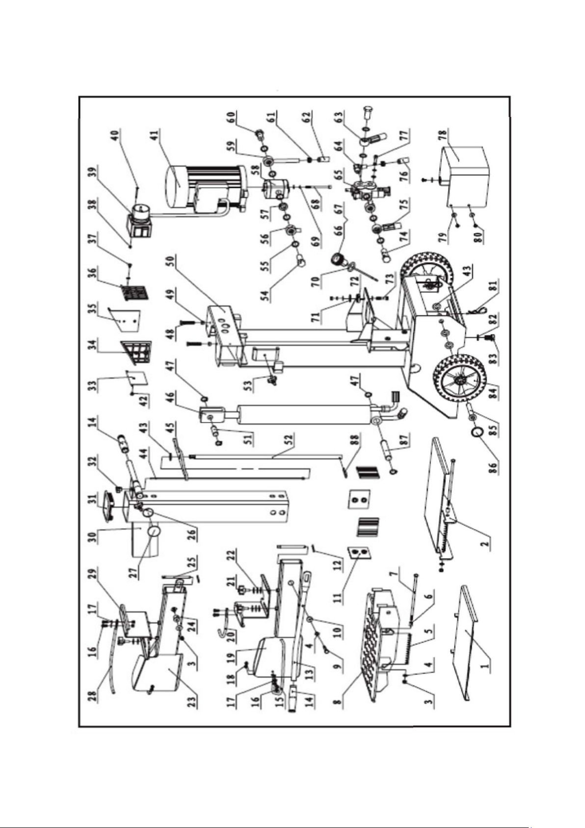
PARTS DIAGRAM – THPLS8TE (1938184001)
Page 22

Item
No
Handy
Part No.
Description
Qty
Item
No
Handy
Part No.
Description
Qty
1
TH245-1
Side Log Support 2
1
45
TH245-32
Lever C1
1 2 TH245-2
Side Log Support 1
1
46
TH246-14
Cylinder C1
1 3 TH245-3
Locknut M8
4
47
TH246-15
Circlip 22
4 4 TH245-4
Washer 8
8
48
TH246-16
Bolt M8x50
2 5 TH245-5
Spring
2
49
TH199-65
Nut M8
5 6 TH245-6
Bush
2
50
TH246-17
Main Frame C1
1 7 TH245-7
Bolt 8.8 M8x210
2
51
TH106-21
Short Shaft D
1 8 TH246-1
Log Support C1
1
52
TH246-19
Tube C1
1 9 TH245-9
Bolt 8.8 M8x60
2
53
TH199-53
Star Knob (black)
1
10
TH245-10
Bush 2
2
54
TH106-54
Oil Plug A1
1
11
TH246-2
Lining Plate
4
55
TH245-34
Washer Groupware 20
10
12
TH246-3
Clip 2.5
2
56
TH106-53
Oil Hose C1
1
13
TH245-13
Handle C1
2
57
TH246-22
Collar
1
14
TH245-14
Handgrip
4
58
TH246-23
Gear Pump C1
1
15
TH245-15
Guard Ring C1
2
59
TH246-24
Nozzle C1
1
16
TH245-16
Screw M6x16
8
60
TH199-74
Oil Plug A2
2
17
TH245-17
Washer 6
6
61
TH246-25
Hose Clamp 18-23(24)
4
18
TH245-18
Locknut M6
8
62
TH246-26
Oil Hose 13
1
19
TH246-4
Right Armguard C1
1
63
TH246-27
Oil Hose C1
1
20
TH245-20
Retainer 1
1
64
TH246-28
Nozzle A
1
21
TH245-21
Star Knob
4
65
TH199-71
CCA Valve
1
22
TH245-22
Big Washer 8
11
66
TH245-39
Oil Cap K
1
23
TH246-5
Left Armguard C1
1
67
Oil Dipstick KG
1
24
TH245-25
Bush 1
2
70
O-Ring 25x2.65
1
25
TH246-6
Pin C1
2
68
TH245-37
Screw M8x90
2
26
TH199-21
Star Knob M6
1
69
TH245-38
Spring Washer 8
7
27
TH199-20
Cap
2
71
TH245-11
Big Washer 10
3
28
TH245-27
Retainer 2
1
72
TH199-67
Motor Support
3
29
TH245-28
Clamp
2
73
TH245-23
Bolt 8.8 M8x45
3
30
TH246-7
Splitting Pipe G5
1
74
TH246-29
Oil Plug A6
1
31
TH106-18
Square Cap
1
75
TH246-30
Oil Hose C1
1
32
TH199-23
Star Knob M5(Black)
1
76
TH246-31
Oil Hose 13
1
33
TH106-23
Upper Lining Plate 2-C
1
77
TH199-77
Screw M8x35
2
34
TH106-24
Upper Lining Plate 4
1
78
TH246-32
Shield C1
1
35
TH106-27
Upper Lining Plate 3
1
79
TH199-14
Big Washer 6
3
36
TH106-28
Upper Lining Plate 1
1
80
TH246-33
Screw M6x10
5
37
TH199-27
Screw M6x8
1
81
TH246-34
Clip 3
2
38
TH199-28
Locknut M4
2
82
TH199-38
Washer Groupware 16
1
39
TH245-29
Switch
1
83
TH199-39
Bolt M16x25
1
40
TH199-29
Screw M4x60
2
84
TH199-42
Wheel
2
41
TH245-30
65585 Motor
1
85
TH246-35
Wheel Axle C1
2
42
TH106-29
Screw M6x10
1
86
TH199-45
Wheel Cap
2
43
TH199-43
Washer 16
7
87
TH246-36
Long Shaft A4
1
44
TH199-52
Pull Rod G5
1
88
TH199-56
Clip 4
1
PARTS LIST – THPLS8TE (1938184001)
Page 23

GJ HANDY & CO LTD USER WARRANTY POLICY
Users Statement of Warranty
Each new machine is warranted against defective material or assembly of material under normal usage. The
warranty applies to the original purchaser and covers faulty parts and the labour involved in replacing and
repairing those parts, which are of original manufacture.
Period of Warranty
Webb (excludes Electric Handheld & Dynamic), Webb Pro, Sanli Engine
a) 2 years from the original date of sale to the first domestic user.
b) 90 days from the original date of sale to the professional/commercial user.
c) 90 days from the original date of sale when used for hire.
d) A reduced warranty period of 90 days applies to those items which are subject to normal wear and tear
(e.g. but not limited to wheels, tyres, cutter bars, cylinders, cutting blades, blade boss, belts, cables, nylon
line & spool, collection bags, spark plugs).
e) Engines are supplied with a separate warranty to the machine. The engine manufacturers warranty
statement which will be supplied within the engine instruction manual. All enquiries and warranty repairs
should be discussed with the engine manufacturer or approved warranty repair dealer.
f) 90 days from the original date of purchase for Replacement Spare Parts (unless normal wear & tear
component, which are covered for 30 days).
g) All machines’ must be serviced within the first 12 months from the original date of purchase to comply
with the warranty, failure to do so will invalidate the 2nd year of the warranty.
All warranty repairs must be undertaken by an authorised service dealer. These dealers have been accredited
by GJ Handy & Co Ltd and agree to only use genuine parts and follow our repair procedures.
Webb Electric Handheld, Webb Dynamic, Handy, Mowerland, Q-Garden
a) 1 year from the original date of sale to the first domestic user.
b) 90 days from the original date of sale to the professional/commercial user.
c) 90 days from the original date of sale when used for hire.
d) A reduced warranty period of 90 days applies to those items which are subject to normal wear and tear
(e.g. but not limited to wheels, tyres, cutter bars, cylinders, cutting blades, blade boss, belts, cables, nylon
line & spool, collection bags, spark plugs).
e) Engines are supplied with a separate warranty to the machine. The engine manufacturers warranty
statement which will be supplied within the engine instruction manual. All enquiries and warranty repairs
should be discussed with the engine manufacturer or approved warranty repair dealer.
f) 90 days from the original date of purchase for Replacement Spare Parts (unless normal wear & tear
component, which are covered for 30 days).
All warranty repairs must be undertaken by an authorised service dealer. These dealers have been accredited
by GJ Handy & Co Ltd and agree to only use genuine parts and follow our repair procedures.
Version 06 (01-18)
Page 24

GJ HANDY & CO LTD USER WARRANTY POLICY
Not covered by this warranty
a) The warranty policy does not cover any depreciation or damages caused by ordinary wear, rusting or
corrosion, lack of correct maintenance or operation, misuse, abuse, lack of transportation or accident.
b) The warranty policy does not cover any costs necessary for the standard periodic maintenance services
instructed by the operator’s manual, or service parts replacement which would include oil, filters, tyres,
belts, brake linings, fuses, blades, seals and other service parts unless it can be proven that the item has
evidence of faulty manufacture.
c) The warranty policy will not cover failure or damage caused as a result of parts or accessories being
modified without the written approval of GJ Handy & Co Ltd.
d) The warranty policy will not cover the unit if non-genuine parts have been fitted and as a result damage
has occurred to the unit.
e) The warranty policy is non-transferable and is only applicable to the original purchaser.
Disclaimer
a) This warranty is only a remedy for defect of products. GJ Handy & Co Ltd will never warranty in terms of
the merchantability or the fitness for a particular purpose.
b) No person is authorised to make any warranties, representations or promises, expressed or implied, on
behalf of GJ Handy & Co Ltd, or to modify the terms conditions or limitation of this warranty policy in any
way.
c) Neither GJ Handy & Co Ltd nor any company affiliated with GJ Handy & Co Ltd shall be liable in any event
or manner whatsoever for incidental or consequential damages or injuries, including, but not limited to,
loss of crops, loss of profit, out of pocket expenses or profits, rental of substitute equipment or other
commercial losses.
General
a) Most warrantable failures show up within the first few weeks of use. These failures are usually
straightforward and warranty assessment is relatively easy.
b) Failures relating to cutter decks and belts need careful investigation, as the cause may not always be
straightforward. Look for damage to blades and pulleys especially when the cutter belt or blade boss have
snapped or cracked as this could be due to impact damage.
c) Customers should always refer to the operator/instruction manual when any disputed problem arises, you
will find most areas covered within the manual.
Version 06 (01-18)
Page 25

NOTES
________________________________________________________
________________________________________________________
________________________________________________________
________________________________________________________
________________________________________________________
________________________________________________________
________________________________________________________
________________________________________________________
________________________________________________________
________________________________________________________
________________________________________________________
________________________________________________________
________________________________________________________
________________________________________________________
________________________________________________________
________________________________________________________
________________________________________________________
________________________________________________________
________________________________________________________
________________________________________________________
________________________________________________________
________________________________________________________
________________________________________________________
________________________________________________________
________________________________________________________
________________________________________________________
________________________________________________________
________________________________________________________
________________________________________________________
________________________________________________________
________________________________________________________
________________________________________________________
________________________________________________________
________________________________________________________
Page 26

NOTES
________________________________________________________
________________________________________________________
________________________________________________________
________________________________________________________
________________________________________________________
________________________________________________________
________________________________________________________
________________________________________________________
________________________________________________________
________________________________________________________
________________________________________________________
________________________________________________________
________________________________________________________
________________________________________________________
________________________________________________________
________________________________________________________
________________________________________________________
________________________________________________________
________________________________________________________
________________________________________________________
________________________________________________________
________________________________________________________
________________________________________________________
________________________________________________________
________________________________________________________
________________________________________________________
________________________________________________________
________________________________________________________
________________________________________________________
________________________________________________________
________________________________________________________
________________________________________________________
________________________________________________________
________________________________________________________
Page 27

Page 28

equipment
For spares or support of your handy product,
please contact us:
Tel: 01793 333212
Email: [email protected]
(Mon – Fri 8.00am to 5.30pm excl. Bank Holidays)
To see our range of garden machinery & equipment visit:
www.thehandy.co.uk
Making gardening easier & affordable since 1938
Distributed by Handy Distribution, Murdock Road, Dorcan, Swindon, SN3 5HY
 Loading...