


Operating manual
Vacuum valve (weight loaded)
12504/ 12818, 12819
1
General ............................................................................................................................................................. 1
2 Safety Information ............................................................................................................................................ 2
3 Delivery, Completeness, Storage ...................................................................................................................... 3
4 Installation, Operation, Maintenance ............................................................................................................... 3
5 Additional Equipment ..................................................................................................................................... 11
1 General
1.1 Manufacturer
Albert Handtmann Armaturenfabrik GmbH & Co. KG
Arthur-Handtmann-Str. 11; D-88400 Biberach
Tel.: +49(0) 73 51/3 42-0; Fax: +49(0) 73 51/ 3 42-44 80
E-Mail: sales.fittings@handtmann.de
1.2 Proper application
Vacuum valves are used in the food, beverage, pharmaceutical and chemical industries.
They are suitable for the protection of tanks and other closed systems against negative
pressure.
During installation, operation and maintenance please pay attention to the generally
accepted safety regulations as well as to the operating instructions.
1.3 Misuse
Misuse is:
• Application in different operating conditions as intended for the specific type.
• Installation, operation and maintenance by unqualified staff.
• Any unauthorized modification of the valve or a valve component.
• On-observance of the operating instructions.
Any misuse will automatically lead to a loss of right to claim under guarantee as well as
any liability.
1.4 Duties of operator
The operator has to make sure that:
• The valve/component is operated properly and only in functional condition.
• The legal requirements are kept during operation and maintenance.
• Only sufficiently qualified and authorized staff maintain the valve/component.
• The staff responsible for operation and maintenance know and obey the
operating instructions and in particular the safety advice.
• The safety and warning signs remain on the valve/component and are
always legible.
1 / 13 Albert Handtmann Armaturenfabrik GmbH & Co. KG 2019-02-08
BA_012504.15_EN

strictly have to be obeyed.
Vacuum valve (weight loaded)
12504/ 12818, 12819
2 Safety Information
Notice and Safety
The following safety advice is an addition to existing national regulations and laws for
accident prevention. Existing regulations and laws for accident prevention always have to
be adhered to. Pay attention to the specific regulations and laws in your country.
The safety advice does not take into account:
• Coincidences and events that may occur during assembly, operation and
maintenance.
• Local safety regulations in responsibility of the operator.
Basic safety advice
Requirements for a proper function of the valve/component:
• Proper transportation and storage
• Installation and setting into operation by authorized staff
• Operation according to these operating instructions – proper application
• Proper and regular maintenance
WARNING
Warning – general dangers!
To avoid danger for health and life the following safety instructions
• Assembly and setting into operation only by qualified staff.
• Instruction and supervision by the operator.
• Keeping of technical and electrical data as specified in the operating instructions.
• Guarantee the electric safety of external devices.
• Keep legal regulations.
Non-observance may lead to the following dangers:
• Malfunction of the valve/component respectively of the plant.
• Danger for persons due to electrical, mechanical and chemical affects.
• Danger for the environment due to possible leakage of dangerous media.
2019-02-08 Albert Handtmann Armaturenfabrik GmbH & Co. KG 2 / 13
BA_012504.15_EN

Vacuum valve (weight loaded)
12504/ 12818, 12819
3 Delivery, Completeness, Storage
• Check the data of the delivery note for factual correctness and the material for
completeness. We regret that money cannot be refunded after purchase.
• Always check the material for transport damages. Possible damages have
to be informed immediately.
• Store the material in a dry place and if possible in its original packaging.
4 Installation, Operation, Maintenance
Wichtiger Hinweis !
• Valve/component suitable for vertical installation.
• Valves with standard weight open at a negative pressure of 3-5 mbar.
Pressure compensation to ambient pressure by air draw in.
The valve will be closed by the counter pressure of the weight.
• Valves with pneumatic lifting open only at a limited counter pressure, i.e. tank
inside pressure. This pressure may not exceed 0.2 bar.
This may cause a malfunction of the valve.
• During the CIP process the pneumatic lifting should be activated only, if the tank
is depressurized. Other-wise, there will be explosion-like pressure
compensation, due to the escaping medium. This mixture of gas and CIP
liquid is splashed into the environment.
• The lifting itself can be performed according to the process requirements. The
duration of lifting should be about 5-20 seconds and can take place during different
cleaning steps. To prevent too strong splashing, the opening gap on the valve can
be adjusted via the stroke on the pneumatic cylinder or lifting takes place during
the startup phase of the pump with reduced power.
Further information can be found in the INFO sheet - IB_CIP lifting VV-SV.02
• During assembly/disassembly please pay attention to the operating instructions
respectively to the type plate or type marking.
DANGER
Danger – General risk!
Lifting the valve during CIP and low tank inside pressure (p < 0.2 bar) causes splashing of
penetrating CIP liquid.
An increasing tank inside pressure can be caused by thermal expansion of the CIP
medium during circulation or by pre-stressing of the tank with CO2/gas.
– Stop spraying of the tank before lifting the valve or de-pressurize the tank.
– Use fully closed splash guard.
3 / 13 Albert Handtmann Armaturenfabrik GmbH & Co. KG 2019-02-08
BA_012504.15_EN

Vacuum valve (weight loaded)
12504/ 12818, 12819
4.1 Assembly instructions
Execution with heating device:
• The heating insets may only be connected according to attached scheme.
Pay attention to the connecting voltage!
• Do not remove the heating inset from the flange during function test
(heating capacity). It may get damaged by overheating.
Execution with external cleaning:
• The external surface of the valve cone is able to be cleaned by an optional
mounted spray pipe.
In this case it is necessary to lift the valve cone. Otherwise the CIP liquid is
damming up within the cylindrically splash guard and runs off through the
drainage drilling to the tank surface (cleaning time 10s, CIP pressure 2 bar).
Execution with lifting device:
• Pneumatic lifting cylinder for function test and for lifting the valve cone
during CIP. The stroke of the lifting cylinder is factory preset.
So the stroke of the valve cone is limited to about 3 mm.
With too large stroke, the emerging splash amount increases.
• Suitable for treated compressed air, max. 6 bar.
• Throttle of air inlet has to be adjusted upon setting into operation.
• Compressed air supply: air hose Ø 6/4.
2019-02-08 Albert Handtmann Armaturenfabrik GmbH & Co. KG 4 / 13
BA_012504.15_EN
Vacuum valve (weight loaded)
12504/ 12818, 12819
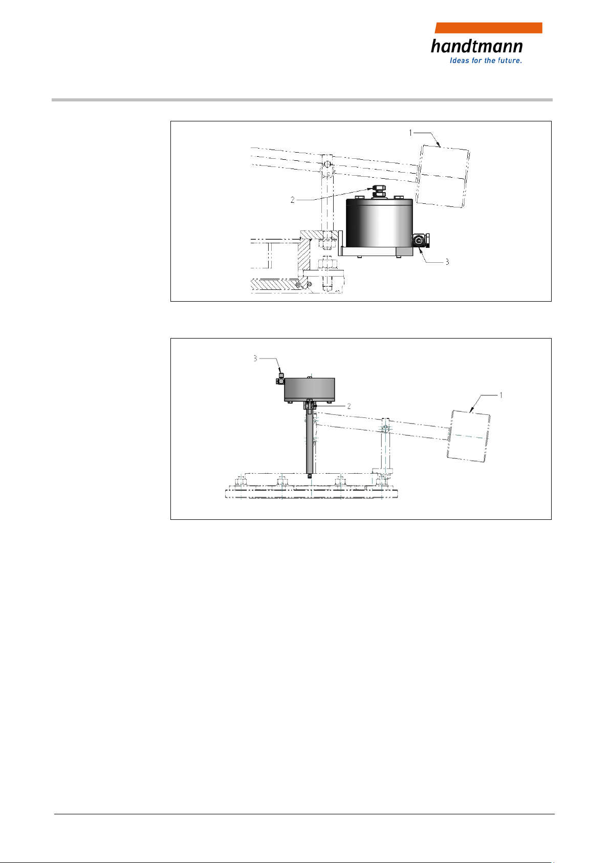
Fig. 1: Schematic representation with lifting device DN 150 – DN 200
Fig. 2: Schematic representation with lifting device für DN 300 – DN 400
1 Counter weight
2 Lifting adjustment
3 Compressed air supply
5 / 13 Albert Handtmann Armaturenfabrik GmbH & Co. KG 2019-02-08
BA_012504.15_EN

Vacuum valve (weight loaded)
12504/ 12818, 12819
Execution with splash guard - Type 12818
Fig. 3: Schematic representation DN 80 – 400
1 Vacuum valve
2 Splash guard
Execution with splash guard and jet pipe – Type 12819
Fig. 4: Schematic representation DN 80 – 400
1 Vacuum valve
2 Splash guard
2019-02-08 Albert Handtmann Armaturenfabrik GmbH & Co. KG 6 / 13
3 Jet pipe
BA_012504.15_EN

Vacuum valve (weight loaded)
12504/ 12818, 12819
4.2 Operation
Type 12504
Construction with stainless steel valve disk DN 80 – DN 400
• Keep the valve clean.
• Lift the valve cone from time to time.
• Exchange the O-ring (1) carefully.
• Avoid any damages at the valve seat.
• Protect vacuum valves from any force influence from outside.
Any damage may affect the function.
• Admissible temperature: 125°C
Fig. 5: with stainless steel valve cone
1 O-ring
2 O-ring (flange)
3 Guiding band
4 Heating inset
7 / 13 Albert Handtmann Armaturenfabrik GmbH & Co. KG 2019-02-08
BA_012504.15_EN

Vacuum valve (weight loaded)
12504/ 12818, 12819
4.3 Maintenance
• Maintain the valve carefully, avoid any damages.
• Dismount the valve.
• Exchange the O-rings (1), (2) and the guiding band (3), do not distort.
Clean the grooves and sealing area.
– The maintenance should be executed at regular intervals of min. every year.
Depending on the operating conditions of the valves, these intervals may be
shorter.
– During maintenance pay attention to the assembly and safety instructions.
– Any maintenance work may be carried out only in a depressurized system.
4.4 Identification of components
All vacuum valves (VV) must be provided with permanent identification of the component.
– Standard vacuum valves are provided with a setting value (4 mbar) specified by us
(opening pressure range 3-5 mbar)
– Special vacuum valves (with special weight) are provided with a
customer-specific setting value.
They also include the identifying letter “S” before the manufacturing №.
Explanation of the identification:
Numerical
code
Allocation 1 2 3 4 5 6
1 Manufacturer
2 Vacuum valve
3 Valve type
4 Nominal width / DN [mm]
5 Set negative pressure p [mbar]
6 Year of manufacture with manufacturing № or “S“ with manufacturing №
AH VV xxxxx xxx yyy xx / xxxxx
AH VV xxxxx xxx yyy xx / S xxxxx
2019-02-08 Albert Handtmann Armaturenfabrik GmbH & Co. KG 8 / 13
BA_012504.15_EN

Vacuum valve (weight loaded)
12504/ 12818, 12819
4.5 Seals
4.6 Spare parts
Fig. 6: Type 12504
10 O-ring
20 O-ring
30 Guiding band
DN 12504 12818 12819
80 012504.00080LE 012504.00080LE 012504.00080LE
100 012504.00100LE 012504.00100LE 012504.00100LE
150 012504.00150LE 012504.00150LE 012504.00150LE
200 012504.00200LE 012504.00200LE 012504.00200LE
300 012504.00300LE 012504.00300LE 012504.00300LE
400 012504.00400LE 012504.00400LE 012504.00400LE
LE - EPDM
9 / 13 Albert Handtmann Armaturenfabrik GmbH & Co. KG 2019-02-08
BA_012504.15_EN
Vacuum valve (weight loaded)
12504/ 12818, 12819
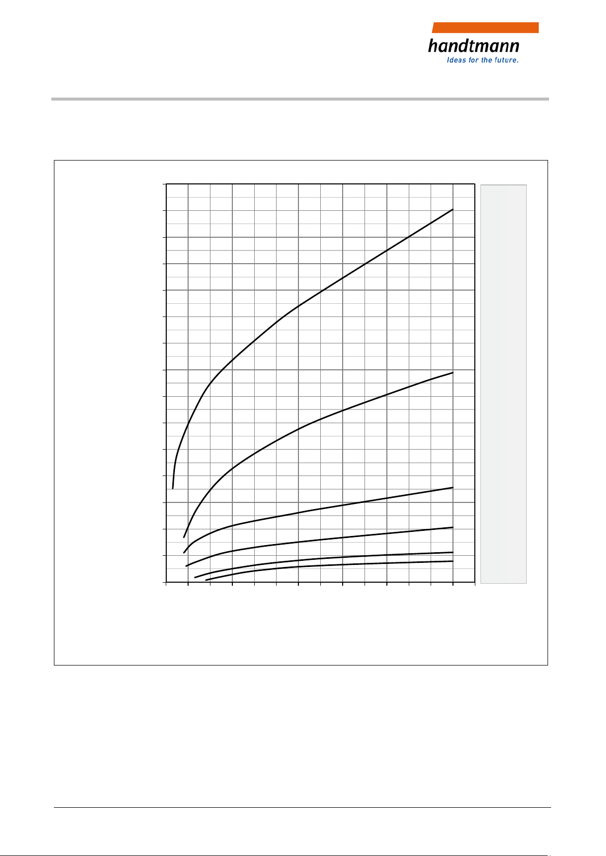
4.7 Performance diagram
15.000
14.000
13.000
12.000
11.000
10.000
9.000
8.000
7.000
6.000
5.000
[Nm³/h]
flow capacity
4.000
3.000
2.000
1.000
DN 400
DN300
DN 200
DN 150
DN 100
DN 080
0
2 3 4 5 6 7 8 9 10 11 12 13 14 15 16
vacuum pressure [mbar-g]
Fig. 7: 12504, DN 80 – DN 400
Conversion: 1 mbar >> 10 mmWS >> 100 Pa >> 0.1 KPa
2019-02-08 Albert Handtmann Armaturenfabrik GmbH & Co. KG 10 / 13
BA_012504.15_EN
Vacuum valve (weight loaded)
12504/ 12818, 12819
5 Additional Equipment
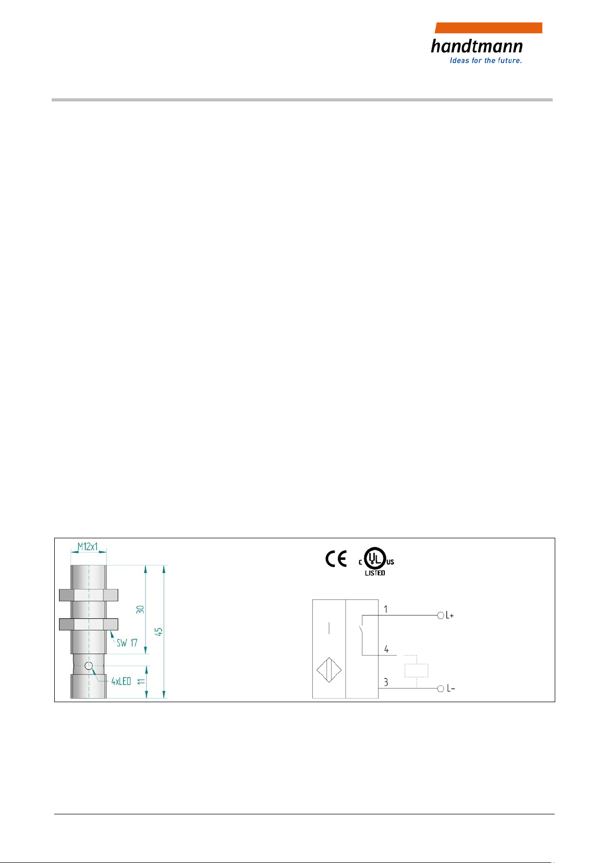
Proximity s witch, induc tive
5.1 Proximity switch, inductive
Type make contact (NO); № 106220 BES M12EE-PSC40B-S04G,
Nominal switching distance
>> with trip cam material steel
>> with trip cam material stainless steel 2,8 mm even
Supply current U 10 ...30 VDC
No-load current bedämpft / unbedämpft max. 10 mA/max. 5 mA
Operating current 200 mA
Potential drop U max. 2,5 V
Switching frequency 200 Hz
Reserve battery protection yes
4 mm even
Short-circuit proof yes
Construction size M12x1
Casing material Stainless steel
Temperature range - 25° C ... + 85° C
Enclosure rating IP 68
Indicator Multi-hole – LED
Fig. 8: Dimensions and connection scheme PNP
11 / 13 Albert Handtmann Armaturenfabrik GmbH & Co. KG 2019-02-08
BA_012504.15_EN

Heating inset Ø 6,5 x 40
Heating inset Ø 6,5 x 40
Vacuum valve (weight loaded)
12504/ 12818, 12819
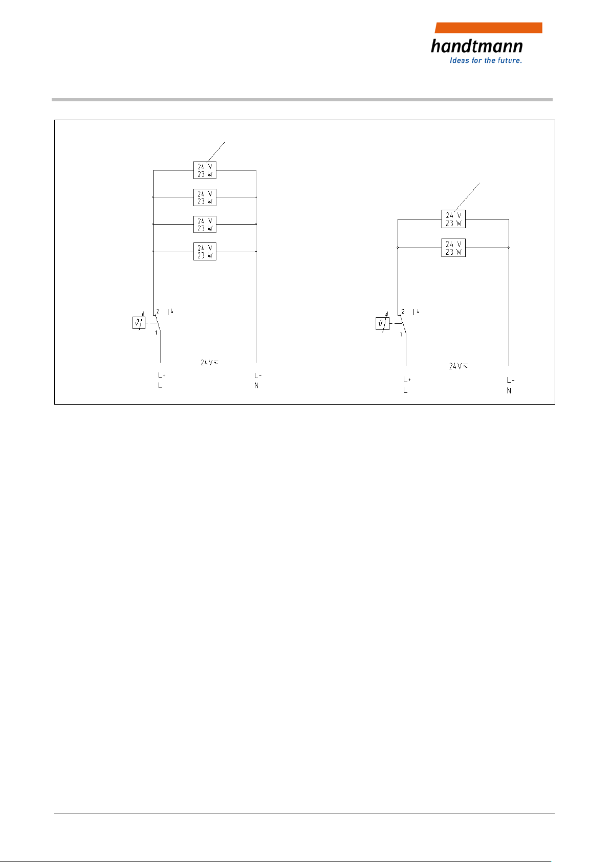
5.2 Heating insets
Heating insets
DN
400 11 125E 33 24 184 8 24 23 105373
300 11 125E10 24 138 6 24 23 105373
200 11 125E30 24 92 4 24 23 105373
150 11 125E31 24 46 2 24 23 105373
100 11 125E31 24 46 2 24 23 105373
Connection-
scheme №
Connection
voltage
Volt
Heating
capacity
Watt
Quantity
Rated power:
Volt Watt
Part №
80 11 125E31 24 46 2 24 23 105373
Temperature
control unit
Temperature
control unit
Fig. 9: E 33, DN 400 E 10, DN 300
2019-02-08 Albert Handtmann Armaturenfabrik GmbH & Co. KG 12 / 13
BA_012504.15_EN
Heating inset Ø 6,5 x 40
Heating inset Ø 6,5 x 40
Vacuum valve (weight loaded)
12504/ 12818, 12819
Temperature
control unit
Temperature
control unit
Fig. 10: E 30, DN 200 E31, DN 80 - DN150
Abb. 11:
13 / 13 Albert Handtmann Armaturenfabrik GmbH & Co. KG 2019-02-08
BA_012504.15_EN
 Loading...