

Page 1
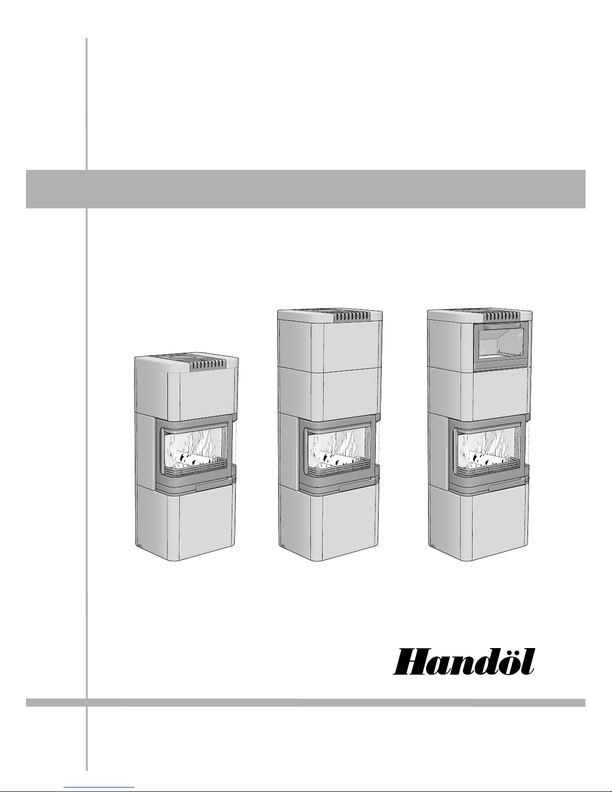
INS TRUCTIONS
26T 26K
Installation
Page 2
GB
74
Quality approval
The stove has been tested by SP
Technical Research Institute of
Sweden and complies with current
CE marking regulations and the
more stringent requirements for
P marking. Certificate number
for P marking: 220312
Manufacturer’s declaration
This product has been
manufactured in accordance with
the documents that constitute the
basis for approval certification
and the relevant criteria for
production control.
Flue requirements
For backward connections from
the rear of the stove and upward
connections from the top of the
stove, the chimney must be able
to withstand temperatures of at
least 350°C.
The Handöl 26 is a Swan
marked wood burning stove.
As the premier stove
manufacturer in Sweden, we at
Nibe Brasvärme are committed
to Swan marking our stoves. Our
commitment to producing stoves
that meet the requirements of
the Swan eco-label is part of our
vision to be a forward-looking
company with high quality goals
when it comes to the environment
too. Eco-label certification no.
378-001.
Certifierad
Certifikat nr
220312
NOTE! Always contact your local authority planning office
before installing a stove.
The owner of the house is personally responsible for ensuring
compliance with the mandatory safety requirements and must have
the installation approved by a qualified inspector.
Your local chimney sweep must also be informed about the
installation as this will affect the routines for regular chimneysweeping services.
378
001
N
O
R
D
I
C
E
C
O
L
A
B
E
L
WARNING!
Some of the surfaces become very hot when the stove is in
use and can cause burn injuries if touched. Please also be aware
of the strong heat radiated through the hatch glass. Placing
inflammable material closer than the safe distance indicated may
cause a fire. Pyre lighting can cause quick gas ignition with a risk
of damage to property and personal injury.
EC declaration of
conformity
Manufacturer
Name NIBE AB
Address Box 134, Skulptörvägen 10, SE-285 23 MARKARYD
Place of manufacture Markaryd, Sweden
Product covered by this declaration
Product type Stove fired by solid fuel
Type designation Handöl 20-series
Type acc. to standard EN 13240 annex ZA
Intended for use Heating of living accomodation
Fuels Wood logs
Special conditions None
CE-marking
Nominal output: 6 kW
Fuel type: Wood logs
Flue gas temperature: 250° C
Energy eciency: 79%
Emission of CO: 0,09%
Safety measurments for
Handöl 20-series: Distance to adjacent combustible materials:
Handöl 24, 26K, 26T
Behind 100 mm, beside 600 mm
Manufacturing check by approved organisation
Notified body No. 0402
Name Swedish National Testing and Research Institute AB
Address Box 857, SE-501 15 BORÅS
Appendix
• Lighting and Installation Instructions
Niklas Gunnarsson
Business area manager NIBE Stoves
www.handol.eu
Page 3

GB
75
CONTENTS
General information 76
Installation distances to walls and ceiling 77
Supply of combustion air 79
Hearth plate, sweeping 80
Chimney connection 81
Installing the surround 82
Installing soapstone /tiles, low model 84
Installing soapstone /tiles, tall model 86
Installing accessories ·baking oven 92
Installing accessories · heat tank 94
DEAR HANDÖL OWNER!
May we take this opportunity to welcome you to the Handöl family.
We hope your new stove will give you a great deal of pleasure.
Your choice of a Handöl stove is testimony to the high standards
you demand in terms of quality and design and you can rest
assured that this stove with its timeless design will be an integral
part of your home for many years.
The stove is not only an efficient source of heat but is
environmentally-friendly as well.
Please read through these instructions carefully before
starting installation work, and study the separate User/Lighting
Instructions before lighting a fire for the first time.
Page 4
GB
76
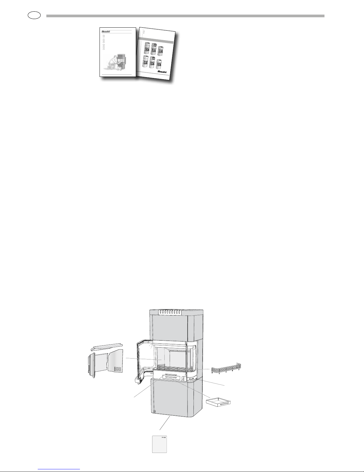
Eldstadsbeklädnad
Rosterreglage
Asklåda
Förbränningsluftsreglage
Brasbegränsare
ANVISNING
26T 26K
ins talla tion s
Installationsanvisning 2
Installasjonsanvisning 25
Installationsanleitung 49
Installation instruction 73
SE
NO
GB
DE
BAV SE/EX 0601-2
511299
Eldningsinstruktion och bruksanvisning för Handöl 20-serien 2
Heizinstruktionen und Gebrauchsanweisungen für Kaminöfen
von Handöl 20 5
Fyringsinstruksjon og bruksanvisning for Handöl 20-serien 8
Fyringsvejledning og brugsanvisning for Handöl 20-serien 11
Istruzioni per l’accensione e consigli per l’uso delle stufe-caminetto
Handöl serie 20 14
Instructions d’allumage et mode d’emploi de la série Handöl 20 17
Stookinstructies en gebruiksaanwijzing voor de Handöl 20-serie 20
Lighting and Maintenance Instructions for Handöl 20 23
Handöl 20-sarjan lämmitys- ja käyttöohje 26
SE
DE
NO
DK
IT
FR
NL
GB
FI
HANDÖL
In accordance with standards below
marking was affixed:
European Standard:
SE Quality Certification, P-marked:
NO Standard NS 3059:
DE and AT Standard DIN 18.891 and
Art 15a B-VG:
Type:
Nominal Output:
Fuel:
Minimun draught:
Flue gas temerature:
Energy efficiency:
Emission of CO in cumbustion products:
Distance to cumbustible wall (mm):
Follow the user’s instructions and use only recomended fuel
NIBE AB Box 134 SE-285 23 MARKARYD SWEDEN
2007
EN 13240
Cert no 0112/07
SINTEF 110-0275
RRF-40 07 13 90
Handöl 31/31A/32/32A
5 kW
Wood
12 Pa
280°C
78%
0,14%
Behind 150
Beside 450
Corner 150
Type plate
Log guard
Fire-box surround
Ash-pan
Grate shuttle
Air supply control
Building application
Before installing a stove or erecting a chimney, you must apply
to your local planning authority for planning permission. We
recommend you contact your local planning office for advice on
building regulations and applying for planning permission.
Structural support
Check that the wood joists are strong enough to bear the weight
of the stove and chimney. The stove and chimney can usually
be placed on a normal wooden joist in a self-contained house
provided the total weight does not exceed 400 kg.
Hearth plate
The stove must be placed on a hearth plate to protect the floor
from any embers. If the floor under the stove is combustible, it
must be protected with a minimum of 12 mm of non-combustible
material that covers at least 300 mm of the floor in front of the
stove door and 100 mm on each side.
Chimney
The draught in the chimney must generate a negative pressure
of at least 12 Pa. The draught is affected both by the length
and cross-sectional area of the chimney, and by how well sealed
it is. The shortest recommended chimney length is 3.5 metres.
The cross-sectional area must be 150-200 cm² (140-160 mm
in diameter). Carefully check that the chimney is sealed and
that there is no leakage around soot hatches and flue pipe
connections.
Note that the draught in the chimney is reduced in a flue with
sharp bends and horizontal sections. A horizontal flue length of
up to 1 metre is permissible, provided that the vertical flue is
at least 5 metres high. It must be possible to sweep the entire
length of the flue and the soot hatches must be easily accessible.
Technical data
Output 3-9 kW
Nominal output 6 kW
Efficiency rating up to 80%
Model H26T/K Tall H26T Low H26K Tall H26K Low
Weight (kg) 470 420 240 240
Widthd (mm) 580 580 580 580
Depth (mm) 462 462 462 462
Height (mm) 1622 1312 1622 1312
Weight H26T with baking oven: 480 kg
Weight H26K with baking oven: 265 kg
Weight Heat tank (Optional accessory for H26 T/K Tall): 120 kg
Air duct connection, external diameter Ø150 mm.
Type approved in accordance with:
European standard EN-13240
Swedish environmental and quality marking, P-marking cert. no.
220306
Norwegian standard NS 3059, SINTEF 110-0223
German standard DIN EN 13240, RRF 4005900
General
information
This manual contains
instructions on how the
Handöl 20 series must be
assembled and installed.
In order to be able to guarantee the performance and
safety of the stove, we recommend that it is installed by a
professional. Our Handöl agents can recommend suitable
installers. For information about our agents, please visit our
website www.handol.se
Instructions for use and how to light the stove correctly are
also supplied with the stove. We recommend that you read
these instructions carefully and keep them safe for future use.
The stove is type approved and must be connected to a chimney
able to withstand temperatures of at least 350°C. The diameter
of the external connection is 150 mm. Air should be supplied
from outside for use as combustion air.
Page 5
GB
77
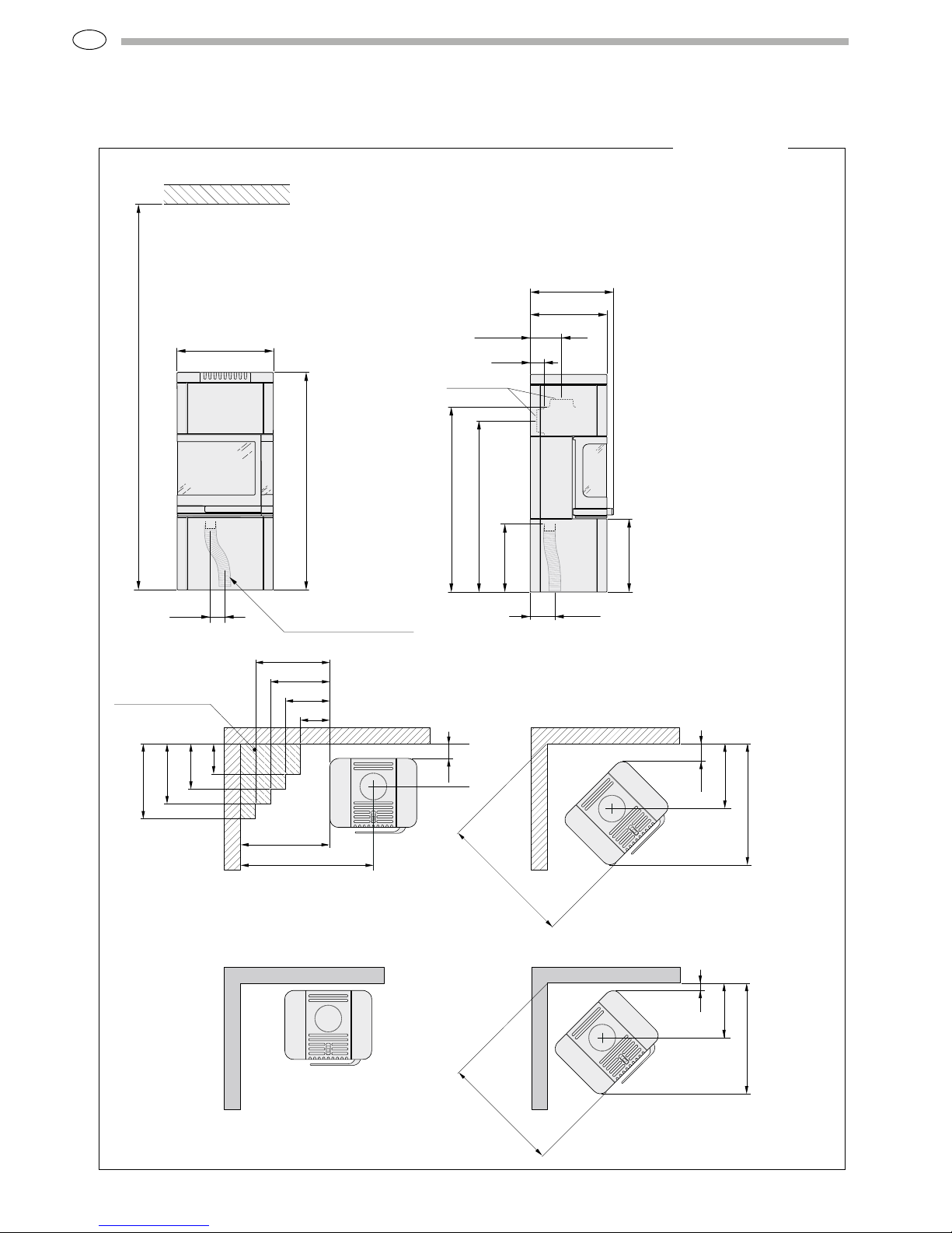
1622
582
2300
G 90
Combustible roof
Combustion air hose
(accessory)
442
E 150
A 1116
1435*
B 1033
F 410
1532*
C 188
D 85
502
462
Utv. Ø150
288
100
600
890
500
400
300
200
300
400
500
200
Combustible wall
Permitted area for
combustible material
435
120
890
810
Combustible wall
H26T/K High
* Used when ins talling optional b aking oven
** To prevent discolouration of painted firewalls, we r ecommended the same side distance as to combustible walls.
238
50
300**
590
Fire-retardant wall of
brick or concrete
365
50
795
740
Fire-retardant wall of
brick or concrete
A = height from floor to upward chimney connection
B = height from floor to c /c rear chimney connection
C = dista nce from back to c/c upward chimney connection
D = distance from back to rear chimney conne ction
E = distance from back to hole in base pla te
F = height from floo r to air inlet (410 mm)
G = distance to hole in ba se plate
Position the stove on a
hearth plate and check that
the installation distances
shown in the diagrams are
met. There must be at least
1 metre between the stove
opening and combustible
parts of the building or décor.
When installing a stove with
a top flue connection to a
steel chimney, please refer to
the relevant manufacturer’s
installation instructions.
Observe the safety distances
to combustible material
required for the steel
chimney.
Installation distances to walls and ceiling
Page 6
GB
78
1312
582
2300
G 90
Combustible roof
Combustion air hose
(accessory)
442
E 150
A 1116
B 1033
F 410
C 188
D 85
Ø150
502
462
* To prevent discolouration of painted firewalls, we r ecomm ende d the same side dista nce as to combustible walls.
A = height from floor to upward chimney connection
B = height from floor to c /c rear chimney connection
C = dista nce from back to c/c upward chimney connection
D = distance from back to rear chimney conne ction
E = distance from back to hole in base pla te
F = height from floo r to air inlet (410 mm)
G = distance to hole in ba se plate
288
100
600
890
500
400
300
200
300
400
500
200
Combustible wall
Permitted area for
combustible material
435
120
890
810
Combustible wall
Fire-retardant wall of
brick or concrete
365
50
795
740
Fire-retardant wall of
brick or concrete
H26T/K Low
Position the stove on a
hearth plate and check
that the installation
distances shown in the
diagrams are met. There
must be at least 1 metre
between the stove opening
and combustible parts of
the building or décor.
When installing a stove
with a top flue connection
to a steel chimney,
please refer to the
relevant manufacturer’s
installation instructions.
Observe the safety
distances to combustible
material required for the
steel chimney.
Installation distances to walls and ceiling
Page 7

GB
79
HK
HK
HK
HK
30 mm
For this type of connection, first remove the vent
screen over the back plate’s air intake.
When connecting an air supply through the floor,
first remove the knockout in the base plate and
hearth plate (if any).
Supply of combustion
air
Combustion air can be supplied through a duct
directly from outside, or indirectly through a
vent in the outer wall of the room where the
stove is installed. The amount of air required for
combustion is approximately 25 m
3
/hr.
The illustrations to the right show various
installation alternatives.
The external diameter of the air duct connection
on the stove is 64 mm.
In heated areas, the duct must be insulated with
30 mm of mineral wool covered with a moisture
inhibitor (construction plastic). It is important
to seal carefully around the duct where it passes
through the wall or floor. Use jointing compound.
If the duct is longer than 1 metre, the diameter of
the duct must be increased to 100 mm and the size
of the wall vent must be increased correspondingly.
A condensation-insulated combustion air hose (1
metre) is available as an accessory.
Page 8
GB
80
Before the stove is used, it must be inspected by an
authorised chimney sweep.
Read the Instructions for Lighting the
Handöl 20 series before lighting the
fire for the first time.
Sweeping
Before sweeping any of the stoves in the
Handöl 20 series, the smoke baffle must be
lifted out. This is easily done by lifting and then
pushing the baffle to the side.
The prefabricated metal hearth plates in the Handöl 20 series have a
hole through which the combustion air hose can pass. Please note that
the illustrations below show the position of the hole in the hearth plate
and not the air inlet on the stove. If connecting an air supply from the
floor, a flexible hose must be used. See illustrations on pages 77 and 78.
190
940
Ø125
Eldstadsplan
320
Hearth plate for the Handöl 20 series (optional)
BAV SE/EX 0601-2
511299
Eldningsinstruktion och bruksanvisning för Handöl 20-serien 2
Heizinstruktionen und Gebrauchsanweisungen für Kaminöfen
von Handöl 20 5
Fyringsinstruksjon og bruksanvisning for Handöl 20-serien 8
Fyringsvejledning og brugsanvisning for Handöl 20-serien 11
Istruzioni per l’accensione e consigli per l’uso delle stufe-caminetto
Handöl serie 20 14
Instructions d’allumage et mode d’emploi de la série Handöl 20 17
Stookinstructies en gebruiksaanwijzing voor de Handöl 20-serie 20
Lighting and Maintenance Instructions for Handöl 20 23
Handöl 20-sarjan lämmitys- ja käyttöohje 26
SE
DE
NO
DK
IT
FR
NL
GB
FI
570
900
Eldstadsplan
Glass hearth plate Metal hearth plate
Hearth plate
Hearth plate
Page 9
GB
81
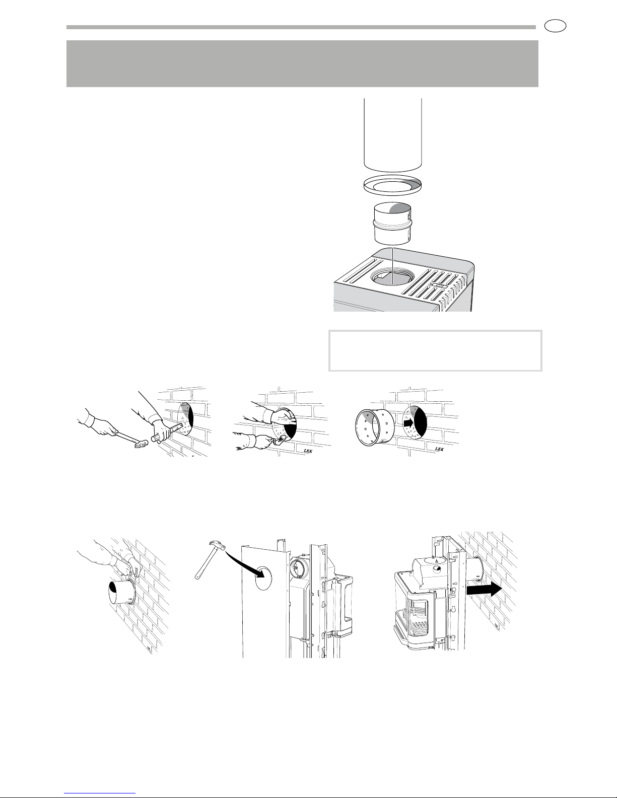
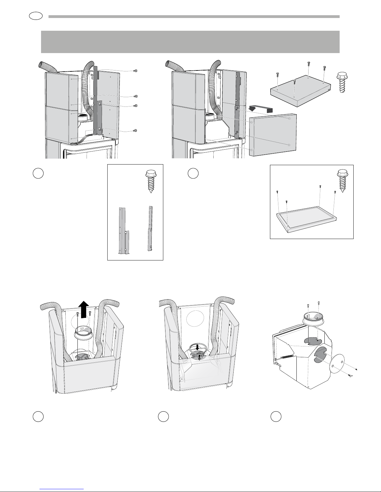
When installing the chimney, please refer to the chimney
installation instructions. The chimney is connected to the stove
as described below.
The insert comes from the factory ready for top connection. When
connecting from the rear, the cover and connection must be swapped
around.
Top connection to the chimney
If connecting from the top, the whole stove surround must be installed
before installation of the chimney can begin.
The start pipe is placed over the connection on the insert. Make sure
that the gasket on the connection is intact and in position. The stop
washer is positioned over the collar on the start pipe. Install the
remaining parts according to the instructions for the chimney.
Chimney connection
Important! If connecting from the top, the hot air
grate must be installed before the chimney.
!
Chimney mantle
Stop washer
Start pipe
Rear connection to a masonry
chimney
Mark out the centre for making a hole in the wall to the flue.
Check that the connection height in the chimney breast is
the same as the height of the connection pipe from the stove.
Make a hole with a diameter of
approx. 180 mm.
Then cement the wall connector
with fireproof mor tar (not
supplied with the product).
Let the mortar dry before the
stove is connected to the chimney.
Move the stove back into place.
Make sure that the connector
gasket does not work loose from
its position. If further sealing
material is required, heatresistant sealant may be used.
Slide the connection pipe into
the wall connector and seal the
joint with sealing rope.
Use a hammer to tap out the
knockout in the back plate.
Hang the back plate into place
on the side profiles as explained
later in these instructions.
Page 10

GB
82
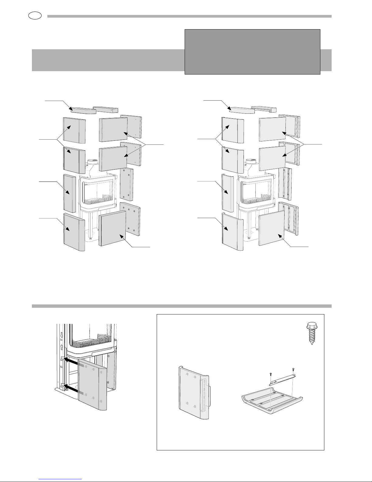
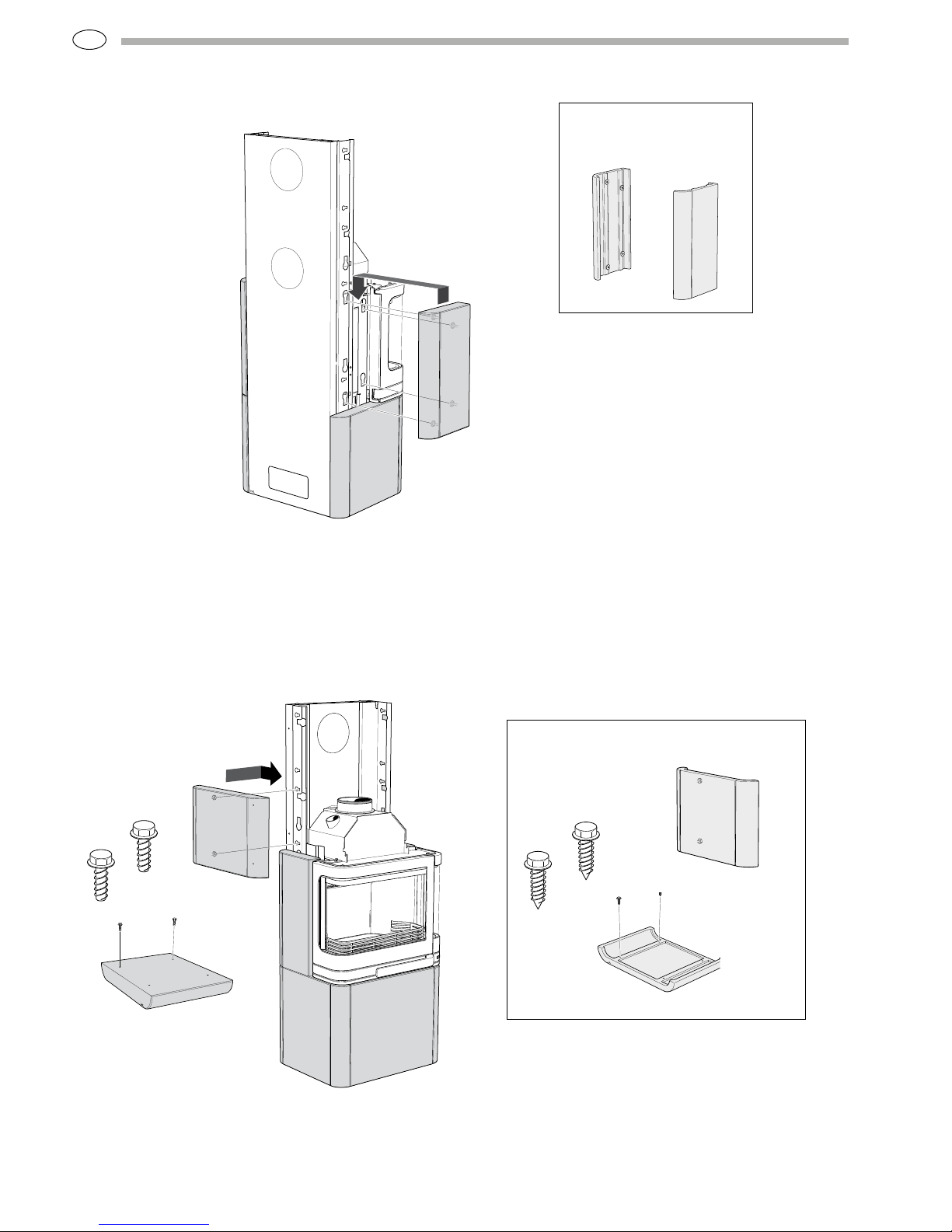
Installing the surround
Handöl 26 T Tall/Low
Handöl 26 K Tall/Low
Type plates
Two type plates are supplied with the stove. One for the
insert and one for the surround kit. Place these plates on
the guide plate as illustrated.
Centre marking chimney
Position the insert and adjust the feet so that the distance
from the guide plate up to the rear edge of the door is
445 mm.Check that the insert is vertically straight.
Position the guide plate according to the installation dimensions
and ensure that it is horizontal. Note that the rear edge of the
guide plate must be 5 mm inside the rear side of the stove.
Remove the insert from the packing and unpack
the surround kit. Read through the whole section on how to install the surround. Check that no
parts are missing or are defective on delivery.
Page 11

GB
83
Tall
Low
Tall
Low
Install the back plate by hanging it in the holes on the side profiles. If the
stove is to be rear connected, this must be done at this stage. Use the upper
outlet on a tall model only if installing a baking oven. Otherwise, use the
lower outlet.
Assemble the rear side profiles with two screws (M6x20) each. Check
that the profiles are resting against the base plate and are vertically
straight. If necessary, use washers between the insert and side profiles to
straighten them.
Page 12

GB
84
TILE
Lower side stone
Assembly
Soapstone and tile stoves are installed in more
or less the same way. These illustrations show
installation of a soapstone model, along with
smaller illustrations of corresponding tiles and
profiles.
H26T Low/H26K Low
Installing tiles
Installing soapstone
403872
Top stone
403871
Upper side stone
403868
Upper front stone
403870
Middle side stone
403869
Lower side stone
403867
Lower front stone
403882
Top stone
403881
Upper side stone
403878
Upper front stone
403880
Middle side stone
403879
Lower side stone
403877
Lower front stone
General information
The stove must be placed on a level and horizontal surface to
ensure that the rows are even and straight, so that the tiles do
not become misaligned or the gaps between them too large.
While you are installing the stove, make sure that all the
stones/tiles are level and that each row is of uniform height
along its length.
Remember that the stones/tiles must be handled with care.
They are easily scratched and sharp edges are vulnerable to
knocks. You should also be careful not to crack the stones/
tiles when screwing in screws.
For the tile model, first screw
two profiles firmly into the lower
side plates. Insert them in the
same way as for the soapstone
model.
Make quite certain that the
rear side profiles are vertically
straight. Push in the lower side
stones from the front so that
their suspension plates hook
into the horizontal keyholes of
the side profiles. Make sure that
there is a 5 mm gap between the
stone and the lower edge of the
door.
Page 13

GB
85
TILE
Middle side stone
TILE
Lower front
stone
H26T Low/H26K Low
Check that the
type plates are in
place.
Hang the middle side
stones into place using
the keyholes in the side
profiles. Then tighten the
screw that is holding the
front side profile in the
insert.
Hook the front side profile onto the
lower side stone’s suspension plate and
secure its upper edge with screws in
both the insert and side profile. Do not
tighten the screw in the insert until the
second layer of side stones are in place.
Install the two, lower front profiles on the lower
front stone so that they are edge to edge with the
short sides of the stone. Insert the front stone
between the lower side stones so that they are
locked into place by the front stone’s profiles.
Page 14

GB
86
TILE
Upper side stone
H26T Low/H26K Low
TILE
Upper front
profile
TILE
Upper front stone
Secure screws into the
upper front stone leaving
4-5 mm between the screw
flange and the soapstone.
Hang the stone into place in
the keyholes and allow it to
rest against the bent edge
of the side profile. Check
that it is at the same height
as the side stones and then
tighten the screws.
Screw the upper front profiles
securely into place in the side stones.
Press the profile upwards so that its
bent edge is against the lower edge of
the side stone.
Secure screws into the
upper side stones leaving
4-5 mm between the
screw flange and the
stone. Then insert them
into the smaller keyholes
in the side profiles and
check that they are level
before finally tightening
the screws.
Page 15

GB
87
H26T Low/H26K Low
TILE
Top stone
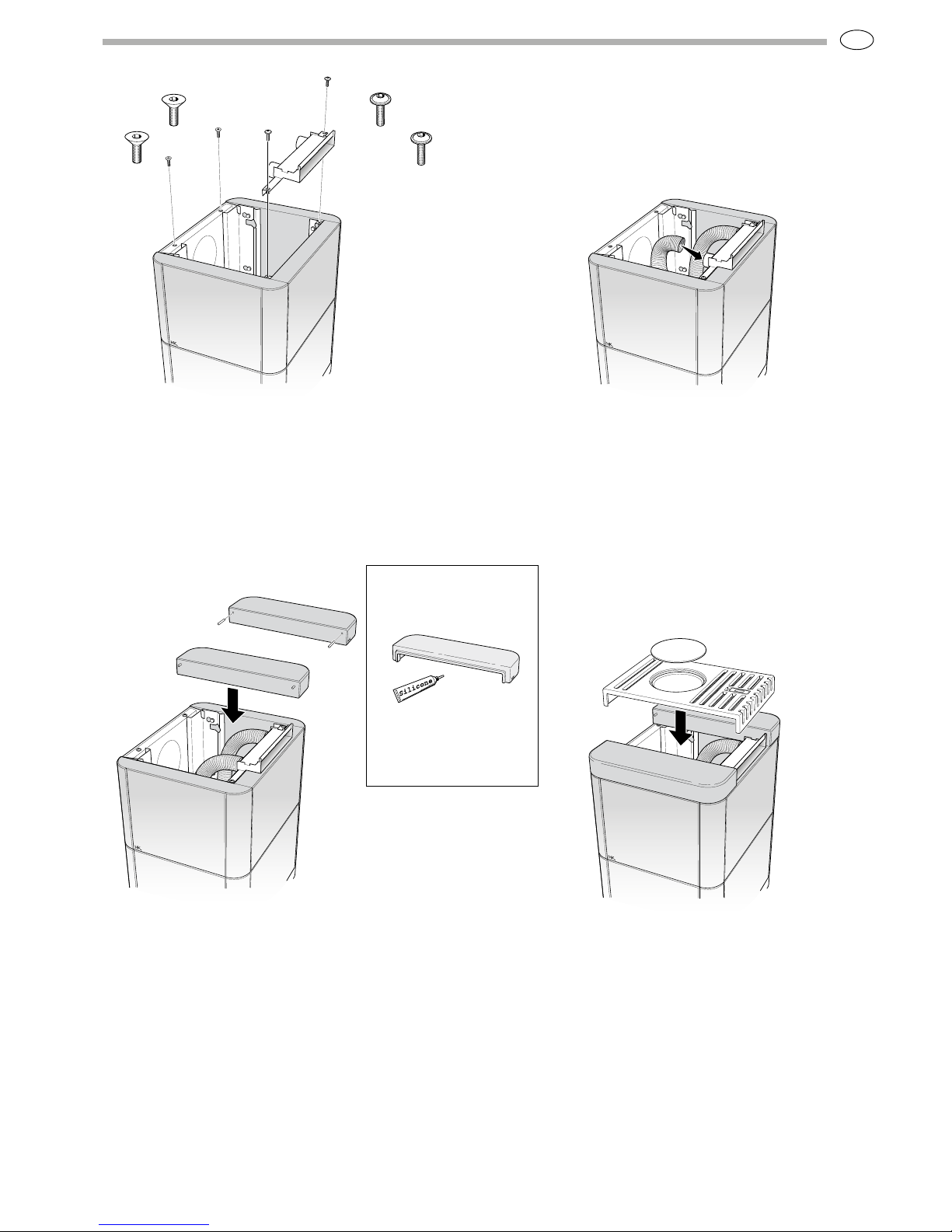
Damper
The top grate damper is regulated using the
control on the top. When the damper is open,
the heated air flows into the room and spreads
the heat. When the damper is closed, a greater
amount of heat is stored in the soapstone, which
releases the heat more slowly and over a longer
period.
Apply a few small drops
of silicone beneath the
tile top to hold it in place.
Carefully place the grate so that it rests on the
pins or the cast edge of the tile top. Check that
the damper can be opened and closed properly.
Position the top stones on top of
the stove. Pins are placed in the
soapstone top for the grate to
rest on.
Position the adjusting screws on the top of the
back plate and screw them down so that the screw
heads are level with the top surface of the upper
side stones.
Screw the convection box securely into the upper
front profiles. Then connect the aluminium hoses
to the convection box.
Place the base plate of the heat tank on the top of the insert. Then place the tank stones as illustrated and push the aluminium
hoses through the holes in the tank stone and down into the convection pipes on the top of the insert. Handle the hoses with care to
ensure they do not crack.
Page 16
GB
88
403882
403881
403880
403877
403878
403879
403872
403871
403870
403867
403868
403869
TILE
Lower side stone
H26T High/H26K High
Installing tiles
Assembly
Soapstone and tile stoves are installed in
more or less the same way. These illustrations
show installation of a soapstone model, along
with smaller illustrations of corresponding
tiles and profiles.
Installing soapstone
For the tile model, first screw two profiles firmly
into the lower side plates. Insert them in the same
way as for the soapstone model.
Make quite certain that the rear side profiles
are vertically straight. Push in the lower side
stones from the front so that their suspension
plates hook into the horizontal keyholes of the
side profiles. Make sure that there is a 5 mm
gap between the stone and the lower edge of
the door.
General information
The stove must be placed on a level and horizontal surface to
ensure that the rows are even and straight, so that the tiles do
not become misaligned or the gaps between them too large.
While you are installing the stove, make sure that all the stones/
tiles are level and that each row is of uniform height along its
length.
Remember that the stones/tiles must be handled with care. They
are easily scratched and sharp edges are vulnerable to knocks.
You should also be careful not to crack the stones/tiles when
screwing in screws.
Page 17

GB
89
TILE
Lower front stone
H26T High/H26K High
Hook the front side profile onto the lower
side stone’s suspension plate and secure
its upper edge with screws in both the
insert and side profile.
Do not tighten the screw in the insert
until the second layer of side stones are
in place.
Install the two, lower front profiles on the lower front stone
so that they are edge to edge with the short sides of the
stone.
Insert the front stone between the lower side stones so that
they are locked into place by the front stone’s profiles.
Page 18
GB
90
TILE
Upper side stone
H26T High/H26K High
TILE
Middle side stone
Secure two (2) screws into the upper side stones leaving
4-5 mm between the screw flange and the stone.
Then insert them into the smaller keyholes in the side
profiles and check that they are level before finally
tightening the screws.
Hang the middle side stones into place
using the keyholes in the side profiles. Then
tighten the screw that is holding the front
side profile in the inser t.
Page 19

GB
91
TILE
Upper front
profile
H26T High/H26K High
>> If installing optional
baking oven, go to
page 92.
Screw the upper front profiles securely into place in the side stones. Press
the profile upwards so that its bent edge is against the lower edge of the
side stone.
Slide the end of the flexible
aluminium hoses down into the
convection pipes on the top of
the insert. (Not when installing
optional heat tank)
Mount the remaining upper side
stones in the same way.
Page 20
GB
92
TILE
Upper front stone
>> If installing optional heat
tank, go to page 94.
H26T High/H26K High
Secure screws into the upper front stone leaving 4-5
mm between the screw flange and the soapstone.
Hang the stone into place in the keyholes and allow it to
rest against the bent edge of the side profile.
Check that it is at the same height as the side stones and
then tighten the screws.
Mount the last front stone in the same way.
Page 21
GB
93
TILE
Top stone
H26T High/H26K High
Damper
The top grate damper is regulated using the control on
the top. When the damper is open, the heated air flows
into the room and spreads the heat. When the damper
is closed, a greater amount of heat is stored in the
soapstone, which releases the heat more slowly and over a
longer period.
Apply a few small drops
of silicone beneath the
tile top to hold it in place.
Final assembly instructions
Carefully place the grate so that it
rests on the pins or the cast edge
of the tile top.
Check that the damper can be
opened and closed properly.
Position adjusting screws on the top of the back
plate and screw them down so that the screw heads
are level with the upper side stones. Slacken the
uppermost screws on the corner profiles. Position the
screen so that it is resting on the corner profiles and
then tighten the screws to secure the screen in place.
Then mount the convection box on the screen.
Screw the convection box securely into the upper
front profiles.
Position the top stones on top of
the stove. Pins are placed in the
soapstone top for the grate to
rest on.
Then connect the aluminium
hoses to the convection box.
Page 22
GB
94
H26T High/H26K High
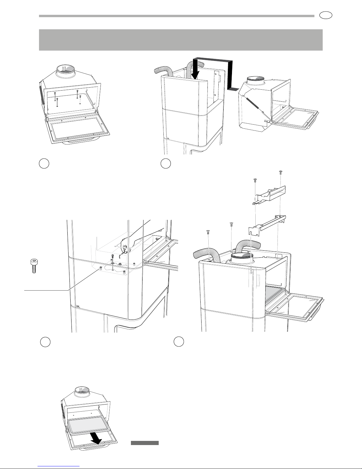
Installing the baking oven (accessory)
TILE
Upper front
profile
TILE
Front stone
Place the sealing ring so that
it is centered over the hole on
the top of the insert. Press the
aluminium hoses into the back
corners so that they are not in the
way of the baking oven.
If connecting upwards,
move the pre-assembled
lid on the baking oven
top to the back.
Remove the connector from
the top of the insert and secure
it onto the back or top of the
oven, depending on whether the
chimney is to be connected from
the rear or directly upwards.
Hang the stone into place in
the keyholes and allow it to
rest against the bent edge
of the side profile. Check
that it is at the same height
as the side stones and then
tighten the screws.
Secure screws into the
front stone leaving 4-5 mm
between the screw flange
and the soapstone.
Securely screw the
corner profiles that are
packed together with
the baking oven into the
upper side stones.
Press the profile
upwards so that its bent
edge is against the lower
edge of the side stone.
1
2
3 4
5
Page 23
GB
95
Justerskruvar
9
H26T High/H26K High
>> Turn to page 91 for final assembly instructions
Installing the baking oven (accessory)
Stone hearth
The hearth at the bottom of the baking oven can be lifted out and washed. If
necessary, rub the surface with a fine sandpaper to restore its appearance. Both sides
of the hearth can be used. When using the stone hearth, it is important to remember
that the stone becomes much hotter than the air in the baking oven. Any food that
spills on the aluminium walls of the oven should be wiped off immediately to prevent it
from burning onto the surface.
Adjusting screw
Position the screen so that it is resting on the corner profiles.
Slacken the uppermost screws on the corner profiles and fasten
the screen into these. Screw the convection box to the screen
and connect the aluminium hoses.
Screw the baking oven onto the insert using the
screws and washers provided. There should be
about 6 mm between the lower edge of the door and
the front stone. Check that the oven is straight. If
necessary, use the four adjusting screws to straighten
it. (Screw the lid back into place in the base of the
baking oven. Place the oven hearth on top.)
Carefully lift the baking oven in
and place it on the insert. Check
that the sealing ring has not
moved out of position.
Remove the lid at the bottom
of the oven.
8
6 7
Page 24
GB
96
>> Turn to page 91 for final assembly instructions
H26T High/H26K High
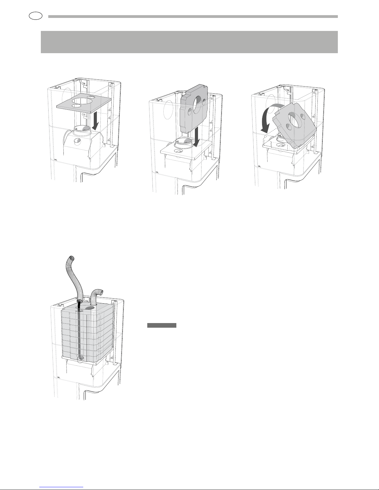
Installing the heat tank (accessory)
IAV SE-EX 1019-3 811008
Place the base plate of the heat tank on the top of the
insert. Then place the tank stones as illustrated and push
the aluminium hoses through the holes in the tank stone
and down into the convection pipes on the top of the insert.
Handle the hoses with care to ensure they do not crack.
Page 25

IAV SE-EX 1019-3 811008
NIBE AB/ NIBE STOVES · Box 134 · 28 5 23 Marka ryd, Sw eden
ww w.han dol.s e
NIBE Stoves re serves the right to change colours,
materials, dime nsions a nd models at any time without
special notice. Your dealer can provide you with the
lates t infor mation. The stoves shown in brochur es
may also f eature optional acc essories or eq uipment.
 Loading...