

Page 1

GB
73
INSTRUCTIONS
34T 35T
Installations
Page 2
GB
74
WARNING!
During operation some of the stove surfaces become
extremely hot and can cause burn injur ies if touched. Be aware
of the strong heat radiated through the hatch glass. Placing
flammable material closer than the safe distance indicated may
cause a fire. Pyre lighting can cause quick gas ignition with the
risk of damage to property and personal injury.
Quality approval
The stove has been tested by the
Swedish National Testing and
Research Institute and meets
the applicable regulations for
CE marking and the stricter
requirements for P marking.
Certif icate number for P
Marking: 01 12/07
Manufacturer’s assurance
Manufacture of the product
has taken place in accordance
with those documents which are
the basis for the relevant type
approval cer tification and the
required manufacturing checks.
Requirements for flue
The chimney must be
dimensioned for at least 350° C
for both top connection directly
upwards and connection directly
backwards from the rear of the
stove.
Handöl 30 is a Swan marked
wood burning stove.
As the premier stove
manufacturer in Sweden, we
at Nibe Stoves are committed
to Swan marking our stoves.
Choosing to Swan mark our
products is one aspect of our
vision to be a company of
the future with equally high
quality standards regarding the
environment.
Certif ication number 378-001.
NOTE! Report installation of a stove to your local authority.
The owner of the house is personally responsible for ensuring
compliance with the mandatory safety requirements and must
have the installation approved by a qualified inspector.
Your local chimney sweep must also be informed about the
installation as this will affect the routines for regular chimneysweeping services.
EC declaration of
conformity
Manufacturer
Name NIBE AB/ NIBE Stoves
Address Box 134, Skulptörvägen 10, SE-285 23 MARKARYD
Place of manufacture Markaryd, Sweden
Product covered by this declaration
Product type Stove fired by solid fuel
Type designation Handöl 30-series
Type acc. to standard EN 13240 annex ZA
Intended for use Heating of living accomodation
Fuels Wood logs
Special conditions None
CE-marking
Nominal output: 5 kW
Fuel type: Wood logs
Flue gas temperature: 275° C
Energy eciency: 80%
Emission of CO: 0,05%
Safety measurments for: Distance to adjacent combustible materials:
Handöl 34T
Behind 100 mm, beside 415 mm
Handöl 35T
Behind 100 mm, beside 415 mm
Manufacturing check by approved organisation
Notified body No. 0402
Name Swedish National Testing and Research Institute AB
Address Box 857, SE-501 15 BORÅS
Appendix
• Lighting and Installation Instructions
Niklas Gunnarsson
Business area manager NIBE Stoves
www.handol.eu
378
001
N
O
R
D
I
C
E
C
O
L
A
B
E
L
378
001
N
O
R
D
I
C
E
C
O
L
A
B
E
L
Page 3

GB
75
TABLE OF CONTENTS
General 76
Installation distance to walls and ceiling 77
Supply of combustion air 79
Removing the loose parts 80
Connection to chimney 82
Installing the surround 34T 84
Installing the surround 35T 88
Installing accessor ies · heat tank 94
DEAR HANDÖL OWNER
We welcome you to the Handöl family and hope that you will
get a great deal of pleasure from your stove. We understand
that you place high demands on both quality and design. As the
new owner of a Handöl stove you have secured a product with
timeless design and long service life.
The stove combustion is also environmentally friendly and
efficient for the best heat production.
Read the installation instructions carefully before you begin
installation and the separate lighting and user instructions
before you light the fire.
Page 4
GB
76
General
This manual contains instructions about how the Handöl
30 ser ies must be assembled and installed. To ensure
the function and safety of the stove, we recommend
that the installation is carr ied out by an authorised
technician. Our Handöl dealers can recommend suitable
technicians,
information about our dealers can be found at
www.handol.eu
Instructions for light ing are also supplied with the stove.
Read them carefully and keep them safe for future use.
The stove is type approved and must be connected to a
chimney dimensioned for at least 350°C, the external
connection diameter is Ø150 mm. Supply air from the
open air should be used as combust ion air.
Building application
Before installing a stove or erect ing a chimney it
is necessar y for you to make a building application
permission to your local authority. Ask your local
authority for advice regarding building regulations and
the application.
Structural support
Check that the wood joists are strong enough to bear
the weight of the stove and chimney. The stove and
chimney can usually be placed on a normal wooden joist
in a single occupancy house if the total weight does not
exceed 400 kg.
Hearth plate
To protect the floor from any ember s the stove must be
placed on a hearth plate. If the floor under the stove is
flammable, it must be protected by a non-flammable
material which covers at least 300 mm to the front and
100 mm on each side.
The hearth plate can consist of natural stone, concrete
or 0.7 mm metal. A painted metal or glass hear th plate is
available as an accessory.
Chimney
The stove requires a draft in the chimney of at least –12
Pa. The draft is affected both by the length and area
of the chimney, and by how well sealed it is. Minimum
recommended chimney length is 3,5 m and a suitable
cross sect ion area is 150-200 cm² (140-160 mm in
diameter). Carefully check that the chimney is sealed and
that there is no leakage around soot hatches and flue
connections.
Note that a flue with sharp bends and horizontal routing
reduces the draught in the chimney. Maximum hor izontal
flue is 1 m, on the condit ion that the vertical flue length
is at least 5 m. It must be possible to sweep the full
length of the flue and the soot hatches must be easily
accessible.
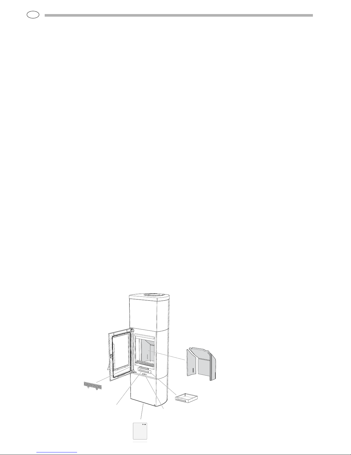
Eldstadsbeklädnad
Rosterreglage
Asklåda
Förbränningsluftsreglage
Brasbegränsare
HANDÖL
In accordance with standards below
marking was affixed:
European Standard:
SE Quality Certification, P-marked:
NO Standard NS 3059:
DE and AT Standard DIN 18.891 and
Art 15a B-VG:
Type:
Nominal Output:
Fuel:
Minimun draught:
Flue gas temerature:
Energy efficiency:
Emission of CO in cumbustion products:
Distance to cumbustible wall (mm):
Follow the user’s instructions and use only recomended fuel
NIBE AB Box 134 SE-285 23 MARKARYD SWEDEN
2007
EN 13240
Cert no 0112/07
SINTEF 110-0275
RRF-40 07 13 90
Handöl 31/31A/32/32A
5 kW
Wood
12 Pa
280°C
78%
0,14%
Behind 150
Beside 450
Corner 150
Technical specifications
Output 3-7 kW
Nominal output 5 kW
Eff iciency up to 80%
Model 34T 35T
Weight (kg) 320 250
Width (mm) 550 550
Depth (mm) 430 430
Height (mm) 1600 1600
Tank stone (kg) 70 70
Connector diameter Ø150 mm ex t.
Type approved in accordance with:
European standard EN-13240
Swedish env ironmental and quality marking, P-marking cer t.
no. 0112/07
Norwegian standard NS 3059, SINTEF 110-0275
German standard DIN 18.891, RRF-40 07 13 90
Rating plate
Fire bars
Hear th cladd ing
Grate control
Combustion air control
Ash-pan
Page 5
GB
77
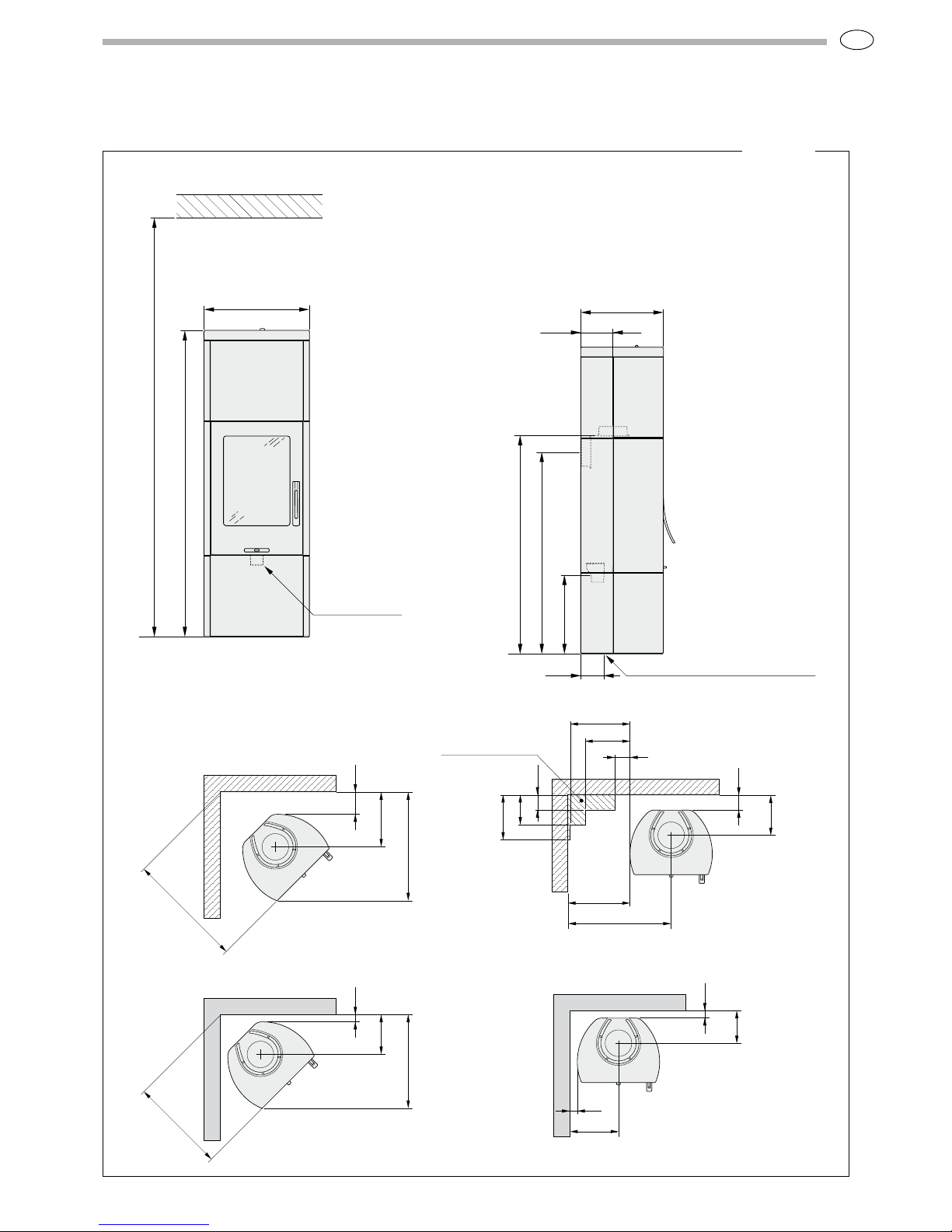
Installation distance to walls and ceiling
550
1600
min 2300
Combustible roof
Air inlet Ø64
120
430
430
1050
1140
167
Hole in foot plate Ø120
Place the stove on the hearth plate and
check that the installation distances
given in the figures below are followed.
The minimum distance in front of the
stove opening to combustible par ts of the
building or interior decoration must be at
least 1 m.
368
150
729
781
Combustible wall
267
100
415
400
300
100
300
200
100
690
Combustible wall
Permitted area for
combustible material
H34T
*To prevent discolouration of painted fire wall s, we recommended the same side distance as to combus tible walls.
268
50
629
640
Fire-retardant wall of
brick or concrete
217
50
50*
325*
Fire-retardant wall of
brick or concrete
When top connecting a steel
flue please refer to the relevant
manufacturer’s installation
instructions. Obser ve the safety
distances to combustible material
that steel flues require.
Page 6
GB
78
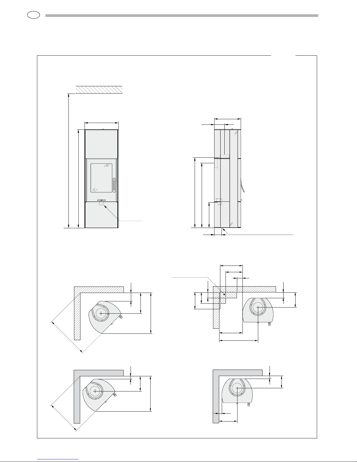
Installation distance to walls and ceiling
550
1600
min 2300
Air inlet Ø64
Combustible roof
430
430
1050
1140
167
120
Hole in foot plate Ø120
Place the stove on the hearth plate and
check that the installation distances
given in the figures below are followed.
The minimum distance in front of the
stove opening to combustible par ts of the
building or interior decoration must be at
least 1 m.
368
150
729
781
Combustible wall
267
100
415
400
300
100
300
200
100
690
Combustible wall
Permitted area for
combustible material
H35T
217
50
50*
325*
Fire-retardant wall of
brick or concrete
268
50
629
640
Fire-retardant wall of
brick or concrete
When top connecting a steel
flue please refer to the relevant
manufacturer’s installation
instructions. Obser ve the safety
distances to combustible material
that steel flues require.
*To prevent discolouration of painted fire wall s, we recommended the same side distance as to combus tible walls.
**
** 1640 with soapstone top
Page 7
GB
79
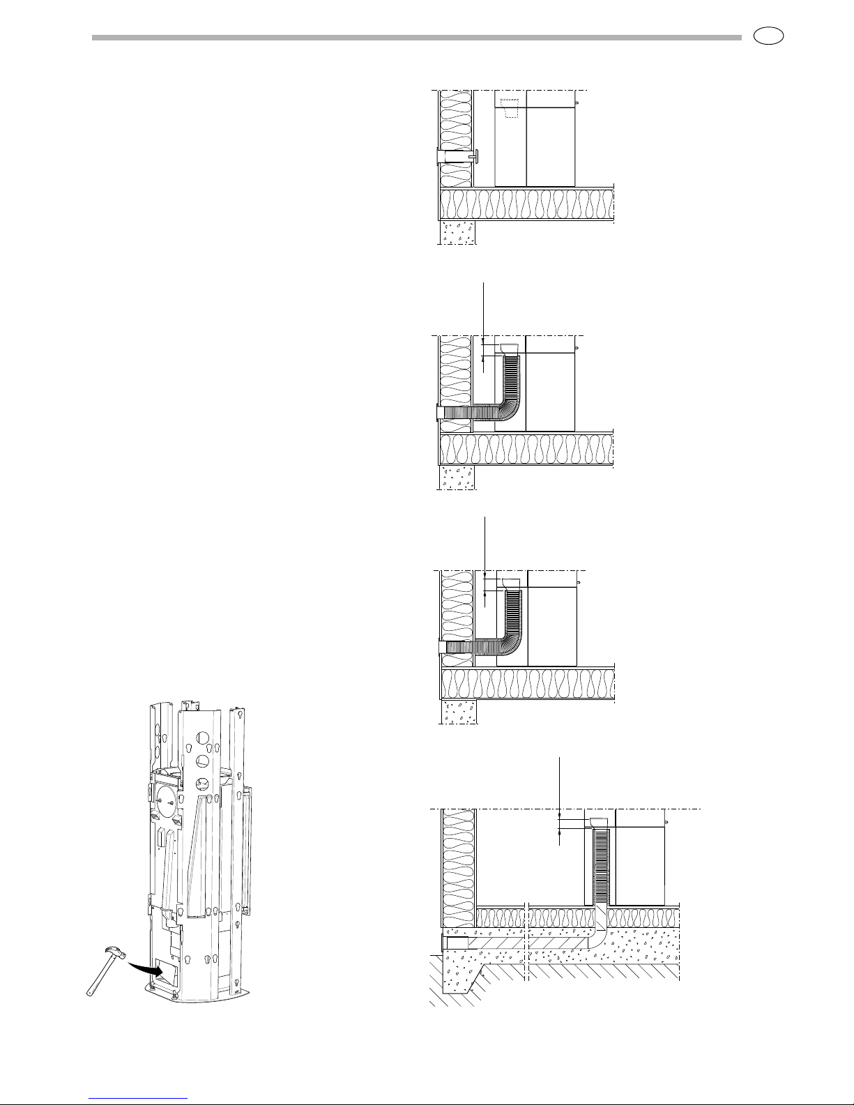
Supply of combustion
air
Combustion air can be provided directly via a
duct from outside, or indirectly v ia a vent in the
outer wall of the room where the stove is to be
placed. The amount of combustion air that is
used for combustion is approx. 25 m
3
/h.
Some installation alternatives are shown to the
right.
The air duct connect ion on the stove has an
external diameter of Ø64 mm.
In hot areas the duct should be insulated w ith
30 mm mineral wool covered with a moisture
inhibitor (plast ic). It is important that the lead-in
between the pipe and the wall (or floor) is sealed
using jointing compound. When duct routing
for fur ther than 1 m the pipe diameter must be
increased to 100 mm and a correspondingly
larger wall vent must be selected.
A 1 m length of condensat ion insulated ducting
for combustion air is available as an accessory.
HK
HK
40 mm
HK
40 mm
HK
40 mm
Knockout
To insert the combustion air hose, tap out the
knockout from the floor panel or leg using a hammer,
remember to protect the floor.
Page 8
GB
80
Unpacking
The insert is secured by four packaging ring angles.
Loosen the screws and remove the angles.
Before the stove is used, it must be inspected by an
authorised chimney sweep.
Read the Instructions for Lighting the Handöl 30
series before lighting the fire for the first time.
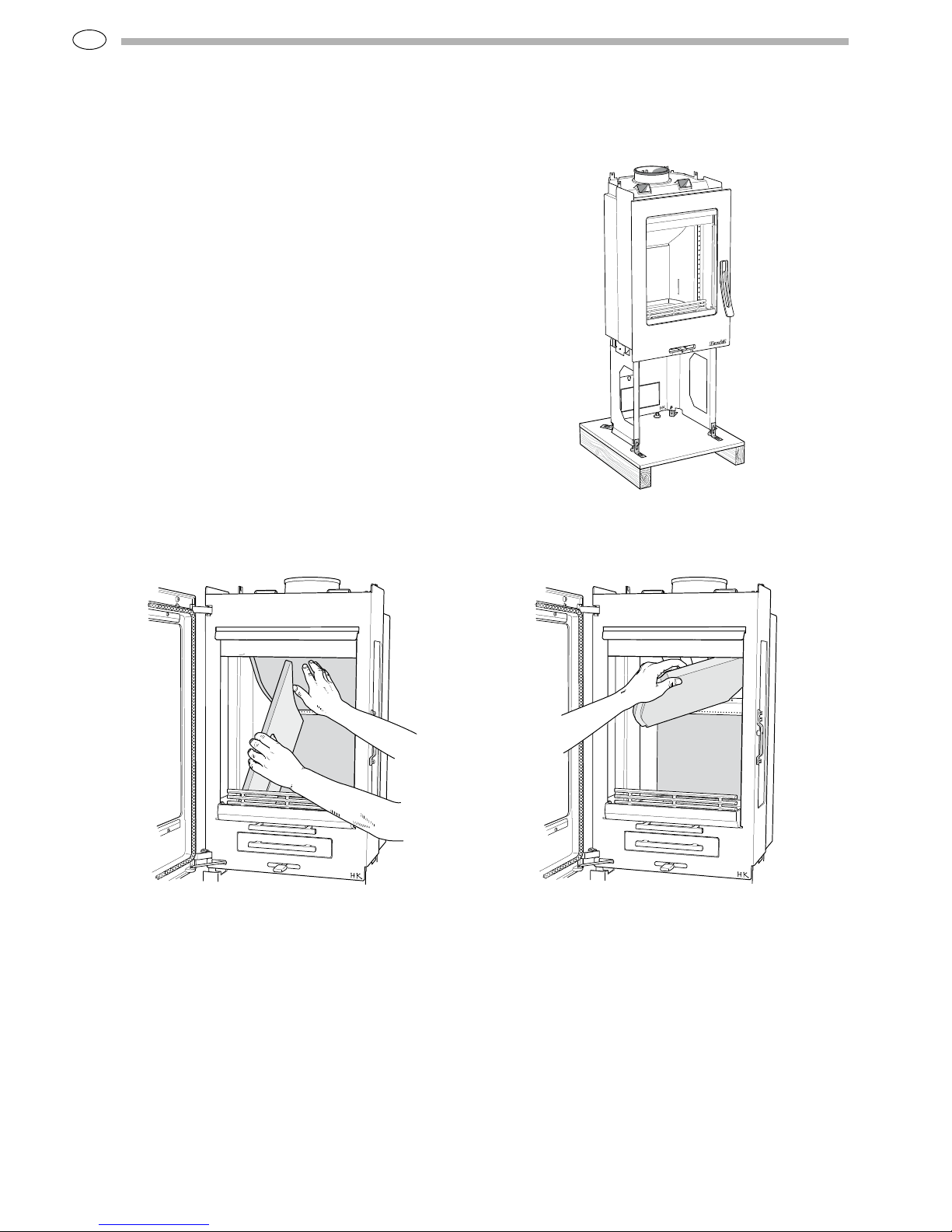
Removing the loose parts
Sweeping
When sweeping, the smoke baffle must be lifted out,
on the Handöl 30 series this can be done by lifting the
smoke baffle and removing the side piece. Lift the smoke
baffle out and remove the remaining sect ions. Handle
the parts with care.
Page 9

GB
81
Self-closing hatch
The stove has a spring to close the hatch automat ically.
The spring is above the heat deflector. The closing
force of the hatch can be adjusted by moving the spring
between the three notches on the lever. The angle of the
stove also affects the closing force of the spr ing.
If the spring force seems weak despite
the spring being mounted at the end of
the lever, the angle of the stove should be
checked.
Type plates
Two type plates are supplied with the stove. One for the
insert and one for the surround kit.
Page 10

GB
82
Refer to the chimney installation instructions. The
following describes how the chimney system is
connected to the stove.
The stove body is prepared for top connection on
delivery. When connecting from the rear, the cover and
connection must be swapped around.
Top connection to the chimney
When connect ing to the top, the whole stove surround
must be installed before installation of the chimney can
begin. Installat ion of the surrounds for the respective
models is described later on in these installat ion
instructions.
The start pipe is placed over the connection on the
insert. Make sure that the gasket on the connection is
intact and in position. The stop washer is posit ioned over
the collar on the star t pipe. The cuff must rest against
the top of the stove. Then install the remaining par ts of
the chimney. The cuff covers the lower sect ion of the
start pipe and facilitates any serv ice work.
Connection to chimney
Chimney mantle
Cuff
Stop washer
Star t pipe
Page 11

GB
83
Rear connection to a masonry chimney
Mark out the centre for making a hole in the wall to the flue. Check
that the connection height in the chimney breast corresponds to the
height of the connect ion pipe from the stove.
Make a 180 mm diameter hole. Then cement in the wall connector with
fireproof mortar (not supplied).
Let the mortar dry before the stove is
connected to the chimney.
Tap out the knock out in the
rear panel using a hammer and
cut the heat deflector on the
rear side of the back panel.
Mount the back plate and
install the connection pipe on
the connection. Make sure that
the gasket does not work loose
from its position. Installation
of the surrounds for the
respective models is described
later on in these installation
instructions.
Seal between the connection
pipe and the connector in the
wall using fire rope. If further
sealing mater ial is required,
heat-resistant sealant may be
used.
Connection to chimney
Page 12

GB
84
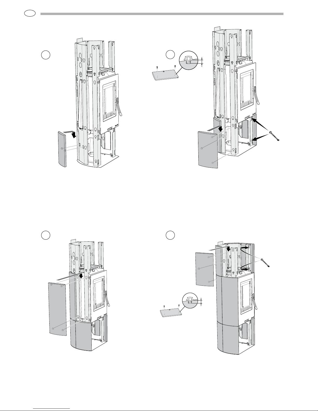
Installing the surround
Handöl 34T
• Unpack the surround kit, grate and top from the
packaging.
• Read through the entire section regarding
installation of the surround. Satisfy yourself that
no components are missing or were defective on
delivery. Handle the parts with care.
• Place the stove on the hearth plate and check the
installation distances.
426 mm
Position the insert on the bottom plate so that the plastic
feet are in the cut-outs.
Adjust so that there is a gap of 426 mm bet ween the top
of the bottom plate and lower edge of the door, check
that the insert is vert ical.
1 2
Place the bottom plate on the floor according to the
installation dimensions. Ensure that it is horizontal, add
steel shims or washers if necessary.
(403961)
(403959)
(403962)
(403960)
(403963)
(403959)
(403962)
(403961)
(403976)
603499
603497
603500
603498
603501
603497
603500
603499
603502
The stones are numbered as illustrated above. We
recommend that the stones are installed in the order
described on the following pages.
Important! Handle soapstone with care. The tiles scratch
easily and may be marked by oil and grease.
Page 13

GB
85
Align the rear side profile lugs in the bottom plate and
hook into the top frame.
Tighten 4 x M6x20 screws a few turns in the top frame
and position it so that the screws locate in the grooves.
Align the front side profile lugs in the bottom plate and
hook into the top frame. Tighten the screws to the top
frame.
IAttach the supplied type plates to the outside of the back
plate according to the figure. Install the back plate by
hanging it from the holes on the side profiles. If the stove
is to be rear connected, connect it now.
4
3
5
6
Page 14
GB
86
3 mm
Install the middle stone casing by hanging it from the side
profiles.
Install the upper side stones in the same way as the lower
side stones.
Screw 2 concrete screws in the front side stones. Leave
3 mm between the stone and the screw flanges. Hook the
front side stone in the key holes and tighten the concrete
screws.
3 mm
Hang the rear side stone in position using the key holes
in the side profiles.
7
9
10
8
Page 15
GB
87
3 mm
419 mm
Install the 4 screws in the upper front stone. Leave 3 mm
between the stone and the screw flanges.
Hang the front stone in the key holes.
Install the adjustment angle pieces on the upper
concrete screws. Adjust the stone so that it is line with
the side stones at the upper edge. Tighten the 4 concrete
screws
IMPORTANT! Check that the distance between the door
and upper front stone is 4 mm. If necessar y, the insert
feet can be adjusted to achieve an even gap between
both front stones and the door.
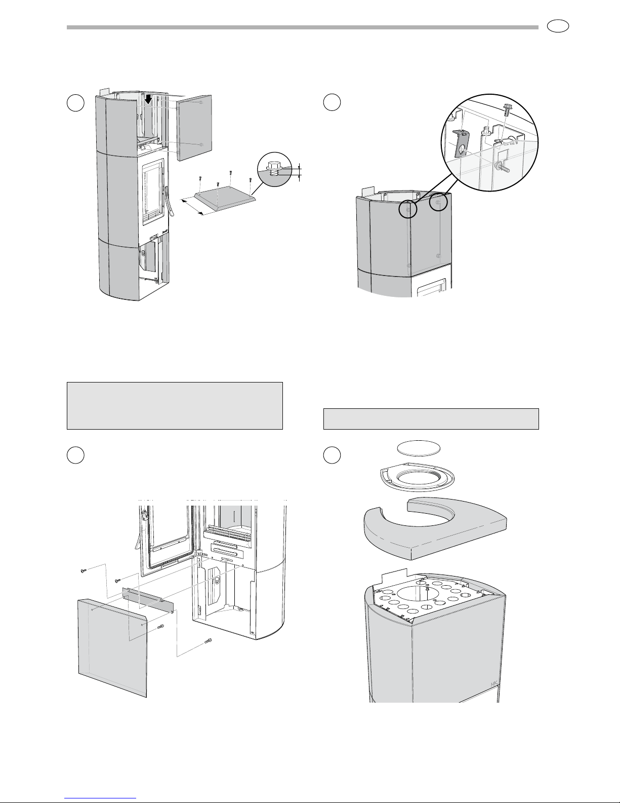
Install the mounting plate at the top edge on the lower front
stone. Position the front stone and secure it using 2 x M5
screws in the body.
11
12
13
14
Mount the upper rib piece on the silicone cones, the screws
must be pointing downwards. Then position the top stone,
grate and cover.
See page 94 for installing the heat tank.
Important
If the fan is to be installed, this must be performed
before installing the lower front stone.
Page 16

GB
88
Installing the surround
Handöl 35T
• Unpack the surround kit, grate and top from the
packaging.
• Read through the entire section regarding installat ion
of the surround. Sat isfy yourself that no components are
missing or were defective on delivery. Handle the parts
with care.
• On the Handöl 35T, the glass on both the insert and the
surround must be cleaned before installation.
• Place the stove on the hearth plate and check the
installation distances.
423 mm
Position the insert on the bottom plate so that the plastic
feet are in the cut-outs.
Adjust so that there is a gap of 423 mm between the top
of the bottom plate and lower edge of the door, check
that the insert is vert ical.
1 2
Place the bottom plate on the floor according to the
installation dimensions. Ensure that it is horizontal, add
steel shims or washers if necessary.
(403957)
(403967)
(403970)
(403966)
(403969)
(403965)
(403968)
(403958)
(403956)
603488
603492
603495
603491
603494
603490
603493
603436
603487
The stones are numbered as illustrated above. We
recommend that the stones are installed in the order
described on the following pages.
Important! Handle soapstone with care. The tiles scratch
easily and may be marked by oil and grease.
Page 17

GB
89
Align the rear side profile lugs in the bottom plate and
hook into the top frame.
Tighten 4 x M6x20 screws a few turns in the top frame
and position it so that the screws locate in the grooves.
Align the front side profile lugs in the bottom plate and
hook into the top frame. Tighten the screws to the top
frame.
Attach the supplied t ype plates to the outside of the back
plate according to the figure. Install the back plate by
hanging it from the holes on the side profiles. If the stove
is to be rear connected, connect it now.
4
3
5
6
Page 18

GB
90
Install 2 x M6x8 screws in the front insert threads of the
side stones. Hang the front side stones in position using
the key holes in the side profiles.
3 mm
Screw the lower front stone using 4 x concrete screws.
Tighten the screws carefully.
Place the upper front stone on top of the front side
stones. Secure using the 4 concrete screws.
IMPORTANT! Check that the distance between the door
and upper front stone is 4 mm. If necessar y, the insert
feet can be adjusted to achieve an even gap between
both front stones and the door.
7
9
10
8
Important
If the fan is to be installed, this must be performed
before installing the lower front stone.
Page 19

GB
91
Hang the side stone in place.
Hang the rear stone in position using the key holes in the
side profiles.
Lift up the valence above the lower stone casing. Insert
the valence flange into the soapstone groove, the
vent ilation grooves must now be facing the front stones.
Insert the valence in the grooves towards the bottom
plate.
Install the glass panels in the same way as the valence.
13
11
12
14
Page 20

GB
92
2
1
Slide the side stone over the glass and the valence. Then
hook the lugs into the key holes.
2
1
Hang the rear stone in place.
18
16
15
17
Slide the front middle stone over the glass and the
valence. Then hook the lugs into the key holes.
Slide the rear middle stone’s lugs into the key holes.
Page 21

GB
93
Install the upper rib on the silicone cones. Then position
the glass top/soapstone top, grate and cover.
19
Page 22

GB
94
Installing accessories · Heat tank
1
3
2
Heat tank to glass top
Place the support plate for the stones on top of the lower
rib piece.
Place the hot air damper on the silicone cones. Then
position the glass panel, grate and cover.
Place the olivine stones on the support plate.
Page 23

GB
95
1
3
2
4
Heat tank to soapstone top
Place the support plate for the stones on top of the lower
rib piece.
Cut off the damper at the rear edge using cutting pliers.
Then break off the damper from the rib at the front edge.
Mount the rib on to the silicone cones. Position the
soapstone top and place the damper in the stone’s
groove. Place the grate and cover in position.
Place the olivine stones on the support plate.
Page 24

GB
96
IAV SE-EX 1037-3 811019
NIBE A B/NIBE S TOVES · B ox 134 · 285 2 3 Markar yd
ww w.handol .eu
Nibe Stoves reserve s the r ight to change colour s,
materials, dimensions and models a t any time
without special notice. Your dealer can prov ide you
with the lates t informa tion.
 Loading...