

Page 1
GB
61
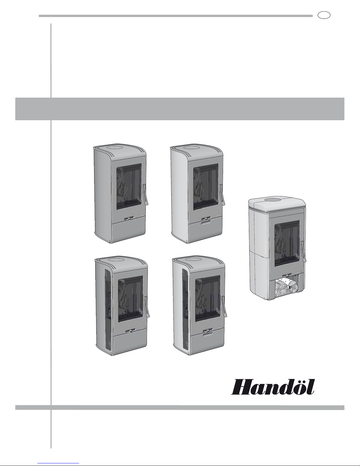
INSTRUCTIONS
Installation
31 31A 32 32A 33T
Page 2
GB
62
Quality approval
The stove has been tested by the
Swedish National Testing and
Research Institute and meets
the applicable regulations for
CE approval and the stricter
requirements for P marking.
Certificate number for
P Marking: 0112/ 07.
Manufacturer’s assurance
Manufacture of the product
has taken place in accordance
with those documents which are
the basis for the relevant type
approval certification and the
required manufacturing checks.
Requirements for flue
The chimney must be dimensioned for at least 350° C for
both top connection directly
upwards and connection directly
backwards from the rear of the
stove.
Handöl 30 is a Swan marked
wood burning stove.
As the premier stove
manufacturer in Sweden,
we at NIBE Brasvärme are
committed to Swan marking
our stoves. Choosing to Swan
mark our products is one aspect
of our vision to be a company
of the future with equally high
quality standards regarding the
environment.
Certifcate number 378-001.
Certifierad
Certifikat nr
0112/07
NOTE!
Notify the local building authorities of the new installation
Report installation of a stove to your local authority.
The owner of the house is personally responsible for ensuring
compliance with the mandatory safety requirements and must
have the installation approved by a qualified inspector.
Your local chimney sweep must also be informed about the
installation as this will affect the routines for regular chimneysweeping services.
EU-declaration
of conformity
Product covered by this declaration
Product type Stove fired by fixed fuel
Type designation Handöl 30-series
Type acc. to standard SS-EN 13240
Intended for use Heating of living accomodation
Fuels Wood logs
Special conditions None
Manufacturer
Name NIBE AB/NIBE Brasvärme
Address Box 134, Skulptörvägen 10, SE-285 23 MARKARYD
Place of manufacture Markaryd
Manufacturing check by approved organisation
Name Swedish National Testing and Research Institute AB
Address Box 857, SE-501 15 BORÅS
Report no / date -/-
Niklas Gunnarsson
Business area manager NIBE Stoves
Appendices
4--!('3) )-.''.%*))-.,/.%*)-
HANDÖL
In accordance with standards below
marking was affixed:
European Standard:
SE Quality Certification, P-marked:
NO Standard NS 3059:
DE and AT Standard DIN 18.891 and
Art 15a B-VG:
Type:
Nominal Output:
Fuel:
Minimun draught:
Flue gas temerature:
Energy efficiency:
Emission of CO in cumbustion products:
Distance to cumbustible wall (mm):
Follow the user’s instructions and use only recomended fuel
NIBE AB Box 134 SE-285 23 MARKARYD SWEDEN
2007
EN 13240
Cert no 0112/07
SINTEF 110-0275
RRF-40 07 13 90
Handöl 31/31A/32/32A
5 kW
Wood
12 Pa
280°C
78%
0,14%
Behind 150
Beside 450
Corner 150
HANDÖL
In accordance with standards below
marking was affixed:
European Standard:
SE Quality Certification, P-marked:
NO Standard NS 3059:
DE and AT Standard DIN 18 891
and Art 15a B-VG:
Type:
Nominal Output:
Fuel:
Minimun draught:
Flue gas temerature:
Energy efficiency:
Emission of CO in cumbustion products:
Distance to cumbustible wall (mm):
Follow the user’s instructions and use only recomended fuel
NIBE AB Box 134 SE-285 23 MARKARYD SWEDEN
2007
EN 13240
Cert no 0112/07
SINTEF 110-0275
RRF-40 07 13 90
Handöl 33T
5 kW
Wood
12 Pa
280°C
78%
0,14%
Behind 100
Beside 415
Corner 100
378
001
N
O
R
D
I
C
E
C
O
L
A
B
E
L
Page 3

GB
63
TABLE OF CONTENTS
General 64
Installation distance to walls and ceiling 65
Supply of combustion air 67
Removing the loose components 68
Connection to the chimney 70
Installing the surround, H31/31A/H32/H32A 72
Installing the surround, H33T 74
Installing accessories · Base 76
Installing accessories · Drawer 77
Installing accessries · Wood compartment 79
DEAR HANDÖL OWNER
We welcome you to the Handöl family and hope that you will
gain much pleasure from your stove. We understand that you
place high demands on both quality and design. As a new
owner of a stove from Handöl you have a stove with timeless
design and a long lifetime.
The stove combustion is also environmentally friendly and
efficient for the best heat production.
Read the installation instructions carefully before you begin
installation and the separate lighting and user instructions
before you light the fire.
WARNING!
The stove becomes very hot when lit
During operation, certain surfaces of the stove
become very hot and can cause burn injury if
touched. Be aware of the strong heat radiated
through the hatch glass. Placing flammable
material closer than the safe distance
indicated may cause a fire. Pyre lighting
can cause quick gas ignition with the risk of
damage to property and personal injury.
Page 4
GB
64
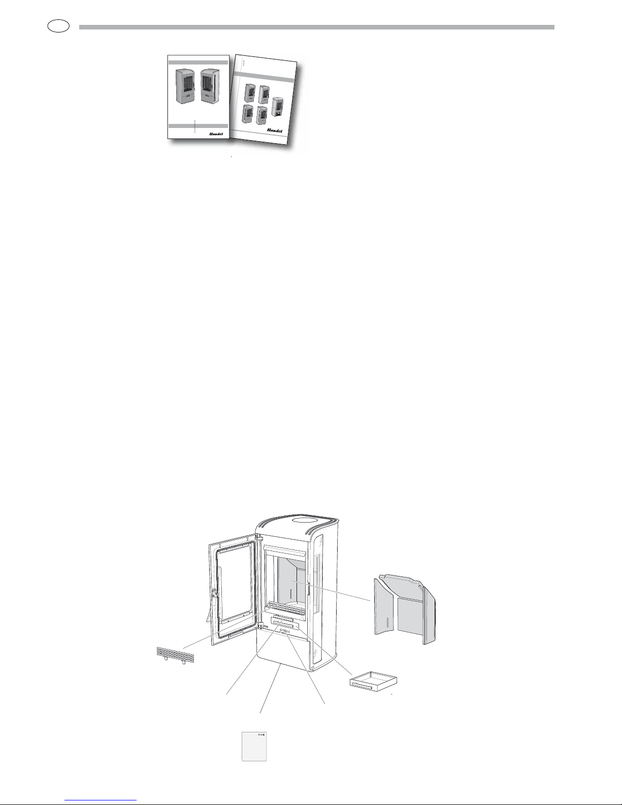
Eldstadsbeklädnad
Rosterreglage
Asklåda
Förbränningsluftsreglage
Brasbegränsare
General
This manual contains
instructions about how
the Handöl 30 series
must be assembled and
installed.
To guarantee the function and safety of the stove we
recommend that it is installed by a professional. Our Handöl
agents can recommend a suitable installer.
Instructions for lighting and use are also supplied with the
stove. Read them carefully and keep them safe for future use.
The stove is type approved and must be connected to a chimney
dimensioned for at least 350°C, the external connection
diameter is Ø150 mm. Supply air from the open air should be
used as combustion air.
Building application
Before installing a stove or erecting a chimney it is necessary
for you to apply for planning permission from your local
authority. Ask your local authority for advice regarding building
regulations and the application.
Structural support
Check that the wood joists are strong enough to bear the weight
of the stove and chimney. The stove and chimney can usually be
placed on a normal wooden joist in a single occupancy house if
the total weight does not exceed 400 kg.
Hearth plate
To protect the floor from any embers the stove must be placed
on a hearth plate. If the floor under the stove is flammable, it
must be protected by a non-flammable material which covers at
least 300 mm to the front and 100 mm on each side.
The hearth plate can consist of natural stone, concrete or 0.7
mm metal. As an accessory, the hearth plate is available in
painted steel.
Chimney
The stove requires a draft in the chimney of at least –12 Pa. The
draught is affected both by the length and area of the chimney,
and by how well sealed it is. Minimum recommended chimney
length is 3.5 m and a suitable cross section area is 150-200 cm²
(140-160 mm in diameter). Carefully check that the chimney is
sealed and that there is no leakage around soot hatches and flue
connections.
Note that a flue with sharp bends and horizontal routing reduces
the draught in the chimney. Maximum horizontal flue is 1 m,
on the condition that the vertical flue length is at least 5 m. It
must be possible to sweep the full length of the flue and the soot
hatches must be easily accessible.
ANVISNING
31 31A 32 32A
33T
installations
I
nstallationsanvisning 2
Installasjonsanvisning xx
I
nstallationsanleitun
g xx
Installation instruction xx
eldnings
instruktion
H
30
Eldningsinstruktion 2
Heizinstruktionen 5
Fyringsinstruksjon 9
Lighting Instructions 13
Fyringsvejledning 17
Instructions d’allumage 21
Lämmity sohjeet 25
Istruzioni per l’accensione 28
Stookinstructies 32
HANDÖL
Technical data
Output 3-7 kW
Nominal output 5 kW
Efficiency level 80%
Model 31 31A 32 32A 33T
Weight (kg) 128 128 128 128 250
Width (mm) 480 480 480 480 550
Depth (mm) 450 450 450 450 460
Height (mm) 1025 1025 1025 1025 1080
The connection’s external diameter is Ø150 mm.
Type approved in accordance with:
European standard EN-13240
Swedish environmental and quality marking,
P-marking cert. no. 0112/07
Norwegian standard NS 3059, SINTEF 110-0275
German standard DIN 18.891, RRF-40 07 13 90
Fire-box surround
Grate shuttle
Ash-pan
Log guard
Air supply control
Type plat e
Page 5
GB
65
480
Tilluftsstos Ø64
1025
2000
Brännbart tak
513
452
189
Tilluftsstos Ø64
Hål i gjuten fotplatta Ø115
A 956
B 865
D 189
C 60
E 103
F 134
Utv. Ø150
392
Brännbar vägg
150
745
817
289
Brännbar vägg
100
450
400
300
100
300
200
100
690
Tillåtet område för
brännbart material
292
Brandmur
50
645
676
239
Brandmur
50*
50
290
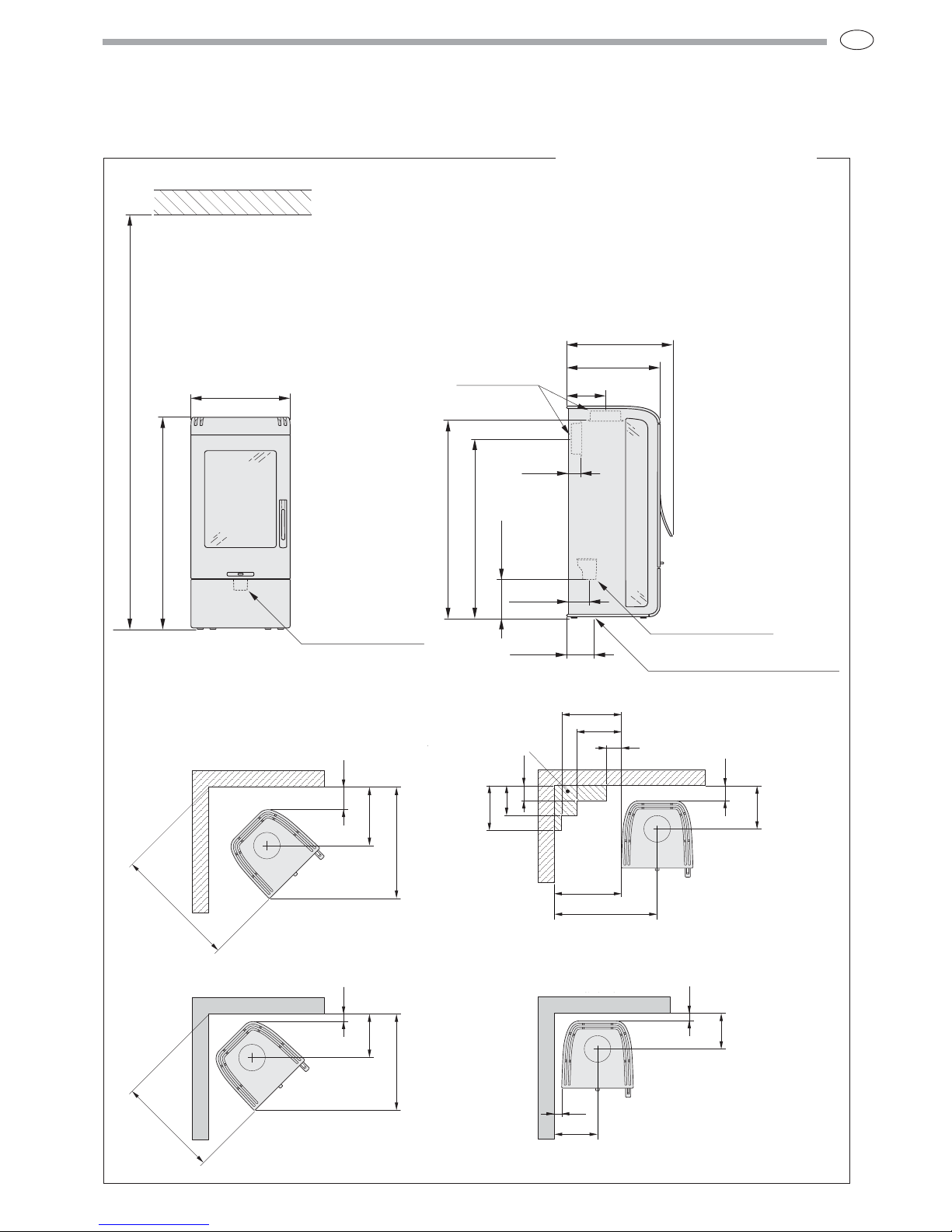
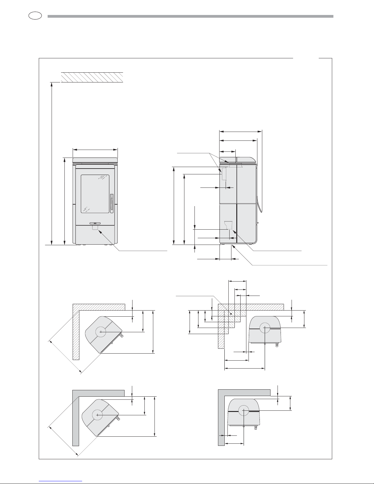
Installation distance to walls and ceiling
Position the stove on a hearth plate and check that the installation distances given
in the diagrams are met. The minimum distance between the stove opening and
combustible parts of the building or décor must be at least 1 m.
When top connecting a steel flue please refer to the relevant manufacturer’s
installation instructions. Observe the safety distances to combustible material that
steel flues require.
H31, H31A och H32 H32A
* To prevent the discolouring of paint ed fire walls, we recommend a side distance the same as for the combustible wall.
A = height from floor to chimney connection
B = height from floor to c /c smoke outlet rear
C = distance from back to smoke outlet rear
D = height from floor to air inlet
E= distance from back to c/ c air inlet
F= distance from back to c /c hole in cast foot plate
Combustible ceiling
Combustible wall
Fire-retardant wall of brick or concrete
Permitted area for
combustible material
.
Combustible wall
Fire-retardant wall of brick or concrete
Air inlet Ø64
Hole in cast foot plate Ø115
Air inlet Ø64
Page 6
GB
66
551
Tilluftsstos Ø64
1073
2000
Brännbart tak
523
462
199
Tilluftsstos Ø64
Hål i gjuten fotplatta Ø120
A 956
B 868
D 189
C 75
E 117
F 141
Utv. Ø150
366
Brännbar vägg
100
732
781
289
Brännbar vägg
100
415
43
300
200
100
300
400
200
100
690
Tillåtet område för
brännbart material
248
Brandmur
50*
50
326
316
Brandmur
50*
682
710
Installation distance to walls and ceiling
Position the stove on a hearth plate and check that the installation distances
given in the diagrams are met. The minimum distance between the stove
opening and combustible parts of the building or décor must be at least 1 m.
When top connecting a steel flue please refer to the relevant manufacturer’s
installation instructions. Observe the safety distances to combustible material
that steel flues require.
* To prevent the discolouring of paint ed fire walls, we recommend a side distance the same as for the combustible wall.
Permitted area for
combustible material.
Combustible wall
Fire-retardant wall of brick or concrete
Combustible wall
Fire-retardant wall of brick or concrete
H33T
A = height from floor to chimney connection
B = height from floor to c /c smoke outlet rear
C = distance from back to smoke outlet rear
D = height from floor to air inlet
E= distance from back to c/ c air inlet
F= distance from back to c /c hole in cast foot plate
Combustible ceiling
Air inlet Ø64
Hole in cast foot plate Ø120
Air inlet Ø64
Page 7

GB
67
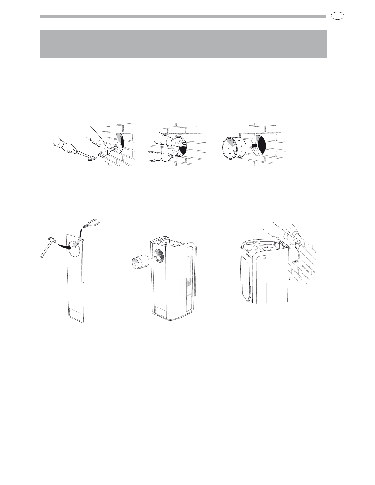
Supply of
combustion air
Combustion air can be provided directly via a duct
from outside, or indirectly via a vent in the outer
wall of the room where the stove is to be placed.
The amount of combustion air used for combustion
is approximately 25 m
3
/h.
Some installation alternatives are shown to the
right. .
The air duct connection on the stove has an
external diameter of Ø64 mm.
In hot areas the duct should be insulated with 30
mm mineral wool covered with a moisture inhibitor
(plastic). It is important that the lead-in between
the pipe and the wall (or floor) is sealed using
jointing compound. When duct routing for further
than 1 m the pipe diameter must be increased to
100 mm and a correspondingly larger wall vent
must be selected.
A 1 m length of condensation insulated ducting for
combustion air is available as an accessory.
HK
HK
HK
HK
30 mm
Knock out
To insert the combustion air hose, tap out the
knockout from the back panel and leg using a
hammer, remember to protect the floor.
Page 8

GB
68
Removing the loose components
Unpacking
Before the stove is used, it must be inspected by an
authorised chimney sweep.
Read the Instructions for Lighting the Handöl 30 series
before lighting the fire for the first time.
Sweeping
When sweeping, the smoke baffle must be
lifted out, on the Handöl 30 series this can be
done by lifting the smoke baffle and removing
the side piece. Lift the smoke baffle out and
remove the remaining sections. Handle the
parts with care.
Page 9

GB
69
Heat deflector
The heat deflector is removed by lifting the front
edge and then pulling it out slightly. Lower it
so that it is below the insert and then withdraw
it. Assembly takes place in the reverse order.
Ensure that the rear lugs are secured in the slits
on the upper leg as illustrated above.
Self-closing hatch
The stove has a spring to close the hatch automatically.
The spring is above the heat deflector. The closing force
of the hatch can be adjusted by moving the spring between
the three notches on the lever. After adjustment, the heat
deflector must be reinstalled. The angle of the stove also
affects the closing force of the spring.
If the spring force seems weak
despite the spring being mounted at
the end of the lever, the angle of the
stove should be checked.
Type plates
Two type plates are supplied with
the stove. One for the insert and
one for the surround kit.
Place these plates on the lower
heat deflector as illustrated. On
the model with the drawer, the
type plates can be mounted inside
the drawer.
Page 10

GB
70
Refer to the chimney installation instructions. The
following describes how the chimney system is
connected to the stove.
The stove body is prepared for top connection on delivery.
When connecting from the rear, the cover and connection
must be swapped around.
Top connection to the chimney
When connecting to the top, the whole stove surround must
be installed before installation of the chimney can begin.
Installation of the surrounds for the respective models is
described later on in these installation instructions.
The start pipe is placed over the connection on the insert.
Make sure that the gasket on the connection is intact and
in position. The stop washer is positioned over the collar on
the start pipe. Remove the small securing plate from the cuff
and thread the cuff over the stop washer. The cuff must rest
against the top of the stove. Then install the remaining parts
of the chimney and finally lock the cuff using the securing
plate. The cuff covers the lower section of the start pipe and
facilitates any service work.
Connection to the chimney
It is important that the cast top is installed on the stove before the
chimney is installed.
Cuff lock
Chimney mantle
Cuff
Stop washer
Start pipe
1
2
Page 11
GB
71
Cut a hole approximately 180 mm in
diameter.
Then cement in a wall connector with
fire proof mortar (not supplied).
Let the mortar dry before the stove is
connected to the chimney.
Tap out the knock out in the
rear panel using a hammer and
cut the heat deflector on the
rear side of the back panel
LEK
LEK
Mount the back plate and install
the connection pipe on the
connection.
Make sure that the gasket does
not work loose from its position.
Installation of the surrounds
for the respective models is
described later on in these
installation instructions.
Seal between the connection
pipe and the connector in the
wall using fire rope. If further
sealing material is required, heatresistant sealant may be used.
Connection to the chimney
Rear connection to a masonry chimney
Mark out the centre for making a hole in the wall to the
flue. Check that the connection height in the chimney breast
corresponds to the height of the connection pipe from the stove.
Page 12

GB
72
Installing the surround
Handöl 31/31A
Handöl 32/32A
s 5NPACKTHESURROUNDKITANDTOPFROMTHE
packaging.
s 2EADTHROUGHTHEENTIRESECTIONREGARDING
installation of the surround. Satisfy yourself that
no components are missing or were defective on
delivery. Handle the parts with care.
s /NTHE(ANDÚL!THEGLASSONBOTHTHE
insert and the surround must be cleaned before
installation.
s 0LACETHESTOVEONTHEHEARTHPLATEANDCHECKTHE
installation distances.
Place these side plates on the lugs in the cast iron
foot as illustrated. Hold the plates so that they do
not tip and become damaged.
Aluminium model
Important: Remove the
protective plastic from along
the rear bent edge before
installing the rear panel.
Remove the protective plastic
once the stove has been
assembled. It is important
to remove all the protective
plastic. Ensure that your hands
are clean to avoid leaving marks on the aluminium sides.
Cleaning
Cleaning must always be carried out with care and on cold panels.
Wipe with a damp cloth and dishwashing detergent and wipe dry
using a clean and dry cotton cloth. For tougher marks, stainless
steel cleaning agent can be used.
Control the top frame as illustrated to fix the sides.
1 2
Page 13

GB
73
Screw the top frame into place on the body
2 1
Place the back panel on the cast feet lugs and carefully
raise the top frame so that the sides do not fall. Guide
in the back panel so that the lugs fix in the side panel
slits
Take out the valence and bend down the small tabs using
pliers so that they fit in the grooves in the top frame.
Place the cast iron top and cover in position.
Check that the top is in line with the sides and door.
4
3
5 6
Page 14

GB
74
Installing the surround
Handöl 33T
s 5NPACKTHESURROUNDKITANDSOAPSTONEKITFROMTHE
packaging.
s 2EADTHROUGHTHEWHOLESECTIONREGARDINGINSTALLINGTHE
surround. Satisfy yourself that no components are missing
or were defective on delivery. Handle the soapstone with
care. In particular sharp edges are vulnerable to knocks.
s 0LACETHESTOVEONTHEHEARTHPLATEANDCHECKTHE
installation distances.
1
2
Place the soapstone holders and back plate in the lugs on the
cast iron foot and attach them to the top frame.
Important! If the stove is to be rear connected
this must be done before the soapstones are hung
in position. If the stove is to be top connected this
must be carried out before the whole surround is
installed.
Apply beads of silicone to the edge between the profiles
and the support plates. Carefully hang the two lower
stones in place. Note that the lower stones have a
rounded edge which is turned downwards unlike the
upper stones which have bevelled edges both upwards
and downwards.
Page 15

GB
75
4
3
5
6
Apply beads of silicone to the edge of the profiles and the
lowest stones. Also apply a blob, near the inside, over the
joint between the lower stones. Hang the upper stones in
position and apply silicone to the edge of the profiles.
Adjust the soapstone panels to each other, door and back.
Screw the top frame into place. Start with the front screws.
Screw the door extension into the door. Leave a 2 mm
gap between the door extension and the door. Slide
down the valence inside the front of the body and
allow the tabs to clamp against the sides of the body.
Apply six small blobs of silicone to each side of the
soapstone sides. Position the top discs and apply eight
small blobs of silicone to the upper side. Then place the
two-piece soapstone top on top of the top discs. Depending
on whether the stove has a rear connection or top
connection, a cover panel or cover ring is used.
Page 16

GB
76
Installing accessories · Base
Base
Take out the components.
When installing the base,
the lower knockout in the
back panel must always be
removed for the supply of
convection air.
Press the front into the snap
fasteners as illustrated.
Position the left hand section
under the stove and screw it into
place as illustrated.
Carry out the equivalent on the
right hand side
1
2
Page 17

GB
77
Drawer
Take out the components.
Installing accessories · Drawer
Remove the front plastic screws in the drawer
rails and discard them. Insert the screws in the
hole of the rail as illustrated. The second screw
is inserted in the rear section. Hold the rail as
far out as possible and angle the front section
downwards whilst you tighten the screws.
When installing the
drawer, the lower
knockout in the back
panel must always be
removed for the supply of
convection air.
1
Page 18

GB
78
Installing accessories · Drawer
Align the drawer mounting as illustrated so that the
drawer mounting notches come under the drawer rail
lugs.
Screw the drawer mounting into place at the front end
using the star screws as illustrated.
Install the drawer on the pull-out unit using the four Allen
screws. Adjust the drawer so that it is centrally positioned in
relation to the hatch and then tighten the screws.
Screw the drawer into place in the cast iron front using
the Allen screws.
2
3
4
5
Page 19

GB
79
Wood compartment
Take out the components.
Installing accessories · Wood compartment
Screw the mounting plate to the cast iron
parts with the Allen screws supplied.
Attach the cast iron component as illustrated
and insert it under the stove. Adjust the pieces
with the Allen screws so that they are in line
with the hatch.
1 2
Page 20

GB
80
IAV SE-EX 0811-4 511941
NIBE AB/ NIBE BRASVÄRME · Box 134 · 285 23 Markaryd
www.handol.eu
Nibe Brasvärme reserves the right to change colours,
materials, dimensions and models at any time without
special notice. Your dealer can provide you with the
latest information.
 Loading...