

Page 1

Page 2

1
Page 3

2
Contents
1 Introduction 3
2 Display codes 4
3 References 6
4 Glossary 7
5 Testing 11
6 Display 12
7 Toggle 12
8 Remotes 12
9 Safety edges 13
10 The batteries 14
11 The battery charger 15
12 Board 16
13 Options 17
14 Rescuing the user 18
15 Faults 19
Page 4

3
1. Introduction
This guide is intended for use as a general reference by engineers repairing faults on
the Handicare Xclusive. The guide is structured as follows: the first chapter provides
general information about the Handicare Xclusive, including how the Handicare
Xclusive should be tested, where the components are located and how they react to
certain situations. The subsequent chapters deal with repairing faults. Flow charts are
used in some cases, where step-by-step choices have to be made in order to find the
cause of the fault.
There is room for improvement in every guide. If you have any tips or suggestions,
please let us know so that we can incorporate them. We wish you the best of luck
with your tasks and hope that this guide will be of assistance.
Page 5

4
2 Display codes
Left hand
Code Meaning Page
None Power off 24
− Charging 23,26
0 General safety circuit activated 22
1 Requires charge 31
2 Off charge 23,26,31
3 Top track limit activated 27
4 Top safety edge activated 29
5 Bottom track limit activated 28
6 Bottom safety edge activated 30
7 Low battery voltage 31
8 UP travel direction 21
9 DOWN travel direction 21
A
B Toggle switch active at power up 21
C IR address fail 32
d Relay not open 20
E Relay not closed 20
F Brake semi-conductor failed 21
G Brake not connected 20
H Relay not open (pre-delay) 20
J
L Current limit exceeded 20
n Low speed 31
o Default Eeprom 21
r Power supply fault during charging 31
Power supply fault when battery on
U
float 31
y Main board hardware fault 21
Page 6

5
2 Display codes
Right hand
Code Meaning Page
None Power off 24
− Charging 23,26
0 General safety circuit activated 22
1 Requires charge 31
2 Off charge 23,26,31
3 Bottom track limit activated 27
4 Bottom safety edge activated 29
5 Top track limit activated 28
6 Top safety edge activated 30
7 Low battery voltage 31
8 UP travel direction 21
9 DOWN travel direction 21
A
b Toggle switch active at power up 21
C IR address fail 32
d Relay not open 20
E Relay not closed 20
F Brake semi-conductor failed 21
G Brake not connected 20
H Relay not open (pre-delay) 20
J
L Current limit exceeded 20
n Low speed 31
o Default Eeprom 21
r Power supply fault during charging 31
Power supply fault when battery on
U
float 31
y Main board hardware fault 21
.||. Overcurrent 20
Page 7

6
3 References page
The general safetyline 22
The direction safetylines 29,30
The end limit switch 22,278
The batteries 24,31
The charger 31
The tractionmotor 21
The brake 21
The display 24
The on/off switch 24
The toggle 23,26
The armrestswitches 23,26
The remotes 32
The infrared receiver 24,32
The fuse 24
The powered swivel 33
The powered footrest 34
The thermal fuse 24,32
Page 8
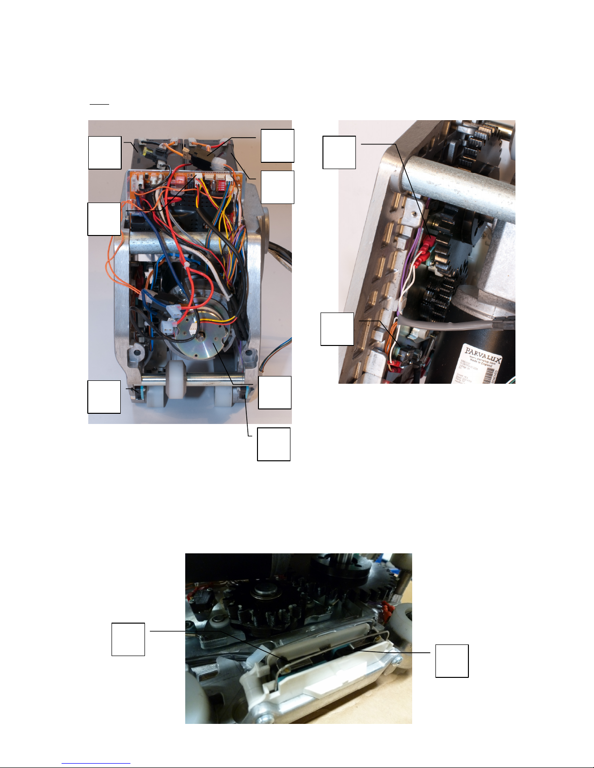
7
4. Glossary
Unit
1
5
9
1 30 amp fuse
2 5 amp fuse
3 Batteries
4 Motor
5 Main board
6 S8 S9 Overspeed governor switch
7 S2, S3 Limit switch
8 S4, S6 Power pack edge switch
9 S5, S7 power pack edge switch
7
2
3
4
8
6
6
7
Page 9
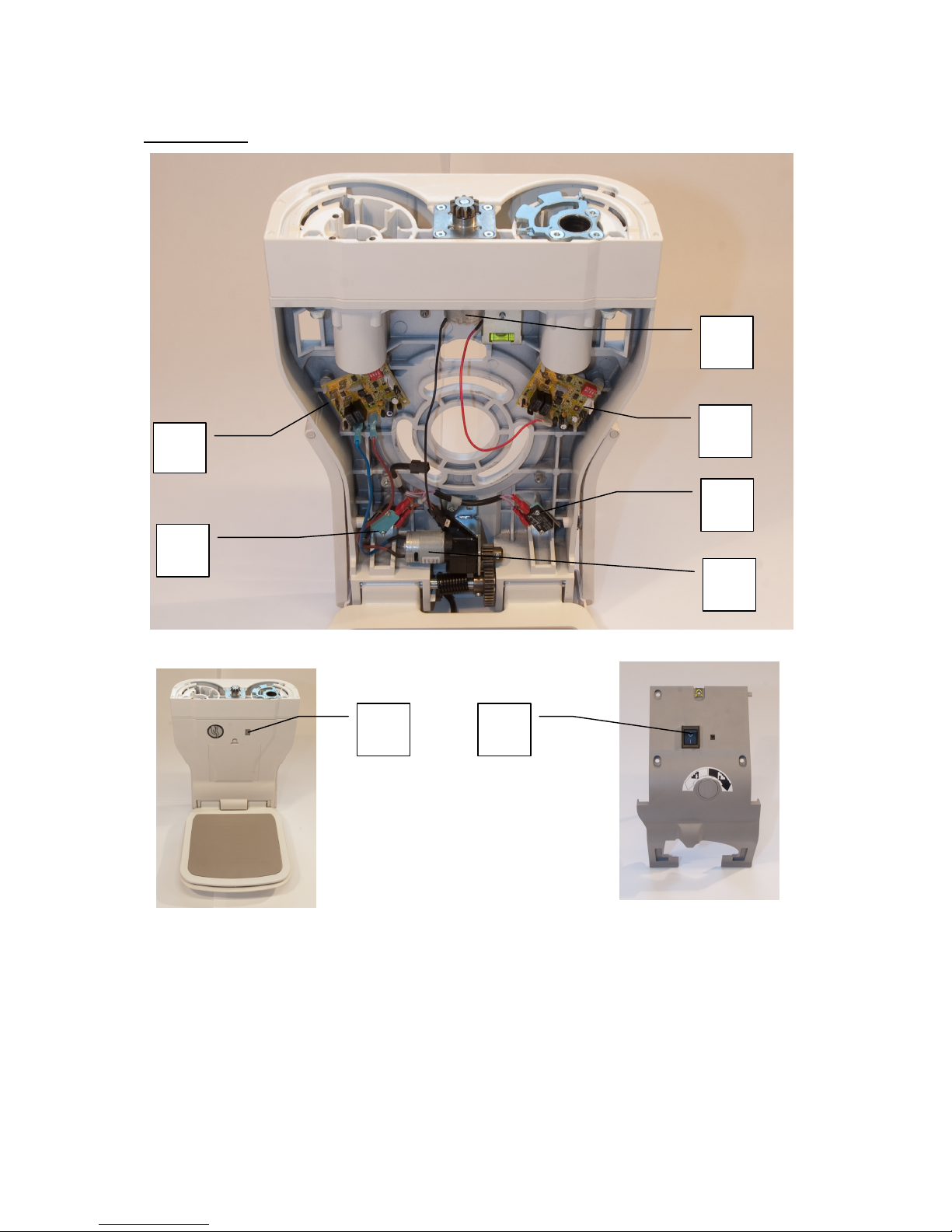
8
Front chassis
1
3
6
2
4
7
8
1 Board powered footrest
2 Board powered swivel
3 S10 front chassis top/bottom edge switch
4 S11 front chassis top/bottom edge switch
5 Powered footrest motor
6 Powered swivel motor
7 Display
8 S1 Main switch
5
Page 10
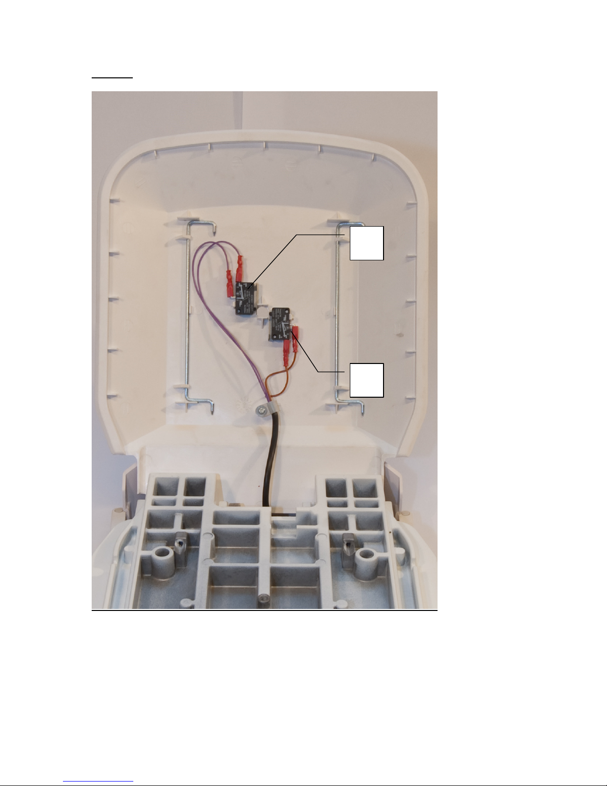
9
Footrest
2
1 Footrest switch S12
2 Footrest switch S13
1
Page 11
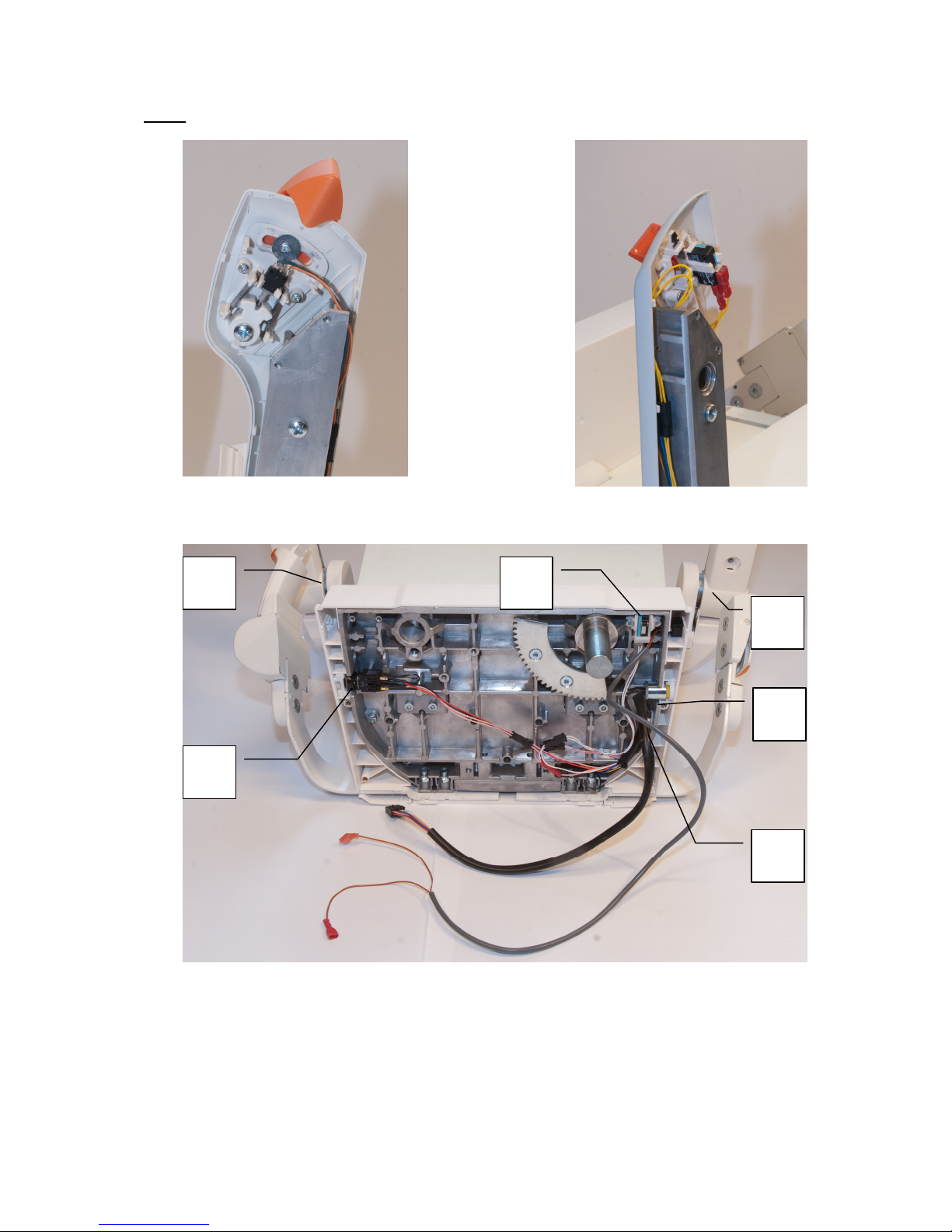
10
Chair
S14 Toggle S15 Control powered footrest
4
5
4
3
1
2
1 S17 Emergency switch
2 S20 Manual overrun autoswivel
3 S18 Keyswitch
4 S21 , S22 Hall sensors
5 S19 Seat swivel switch
Page 12

11
5. Testing
The circuits should be tested as follows:
• Use the electrical diagram to see which circuit you need to test
• Disconnect the Handicare Xclusive from the power supply
• Connect the molex testing link to the pcb
• Set the multimeter to the “beep” or resistance or voltage test mode
• Remove the correct connector from the board
• Push the measuring pins into the back of the connector (see photo).
• Check that you are testing between the correct connector pins/numbers.
• No “beep” or resistance means that the circuit being tested is not complete.
If there is a short circuit with the frame, hold one of the measuring pins against the
unit’s ground pin of the seat and push the other measuring pins into the back of the
connector.
Molex testing link
Page 13
12
6. Display
On the lift is a display which shows a diagnostic code to help you locate the cause of
the breakdown. The codes can be found in the user- and installation manual. See
also chapter 15.
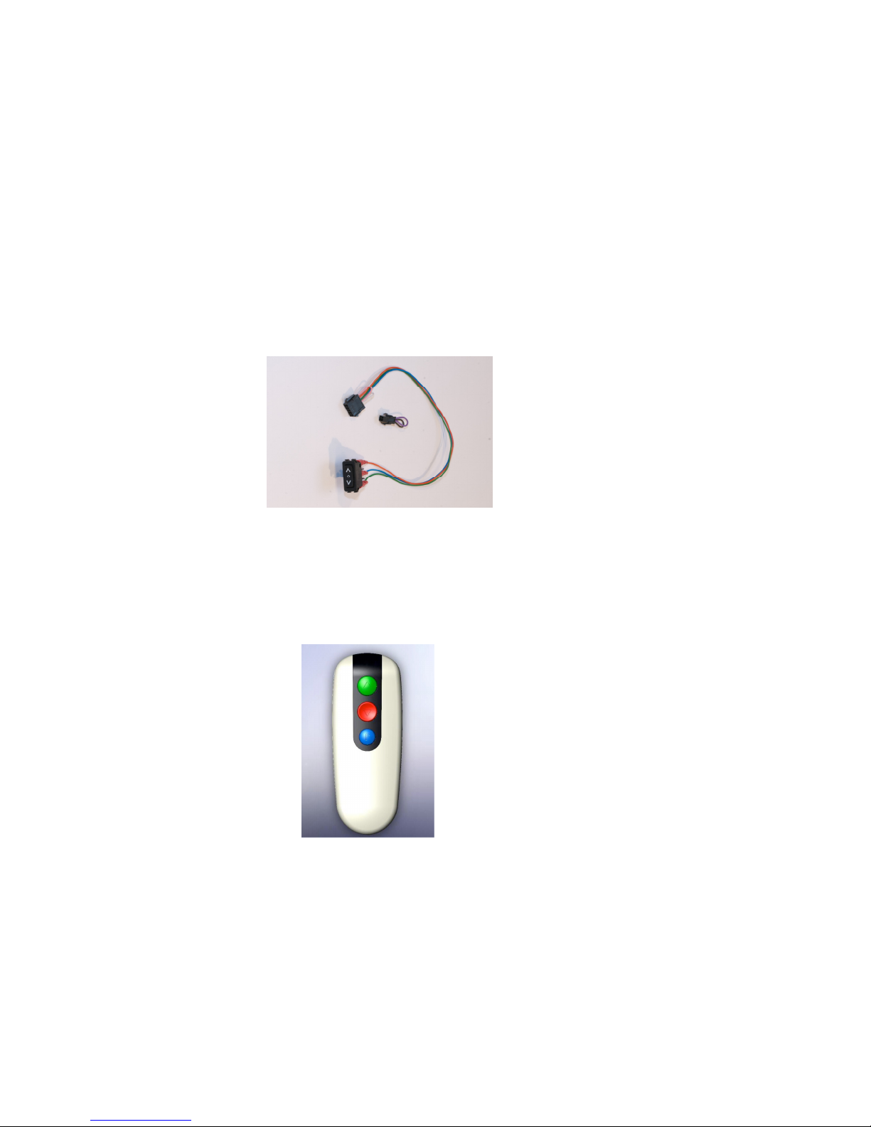
7. The toggle
The lift is operated by the toggle on the armrest. The toggle or the button for the
powered footrest raiser can be swapped from right to left on side.
The lift will not ride when the armrests are in the folded position. It does however
operate on the remotes. During the ride the diagnostic display show “8” or “9”.
An installation toggle loom can be used to ride the power pack without chair.
In case of a public building when the key switch should switch off the toggle but the
remotes should stay operational, the key switch needs to be transferred from the
safety line to the control line.
8. The remotes
The remotes function on infrared and they need to be fixed to the walls adjacent to
the stairlift. On the backside is a dipswitch for setting a different code.
The lower button is a special button for parking the lift. On the backside is a red or
green cover. Green means the remote functions on radiofrequency (2,4 Ghz), red
means the remote functions on infrared.
Under this cover you can find a dipswitch to set a different canal.
The infrared remotes work out of the box. If they don’t, they can be linked as follows:
Press and hold the red button on the board P1. A yellow light will illuminate on the
board. Press any button on the handset and the light will go out.
Page 14

13
9. The safety edges
Two direction-sensitive safety edges and one general safety edge have been
included in the Handicare Xclusive.
The direction-sensitive safety edges
The direction-sensitive safety edge prevents the lift from moving further in the
direction that is blocked.
However, the Handicare Xclusive can still be moved in the opposite direction to
remove the blockade.
The diagnostic code shows “4” or “6”
The following switches have been included in the direction-sensitive safety edge:
• Footrest switches
• Detection switches for the power pack
• Detection switches for the front chassis
The handing of the safety edges is when sitting on the lift.
The general safety edges
The general safety edge prevents the lift from moving further in both directions.
The diagnostic code shows “0” when the toggle is moved in either direction when the
safety edge is obstructed.
The following switches have been included in the general safety edge:
• Seat swivel switch
• Overspeed governor switch
• Key switch
• The emergency stop
When the key switch or the emergency switch are activated, nothing will function
When the safety brake or the seat swivel switch are activated the lift won’t move, but
the option automatic swivel and powered footrest are still operable.
Page 15
14
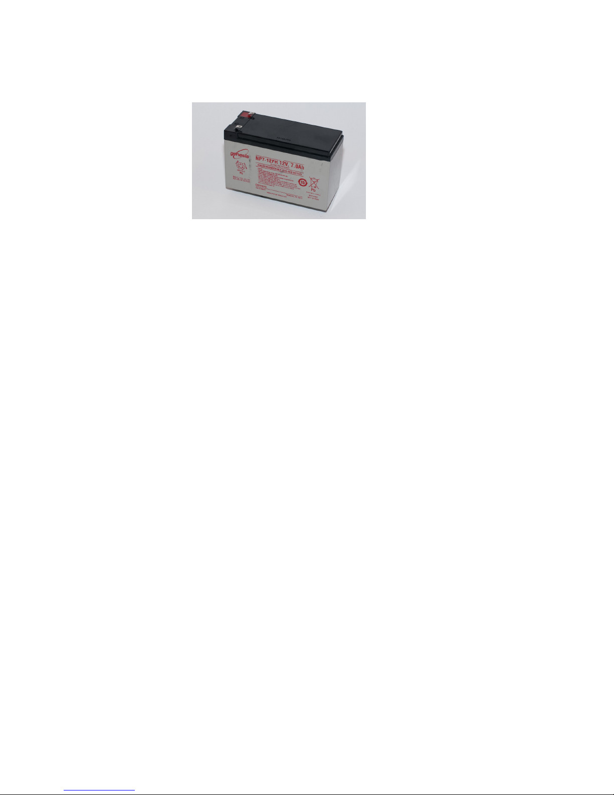
10. The batteries
Two 12V 7 Ah maintenance-free lead-acid batteries are used. They have an
expected life span of three years.
If the output voltage of one of the batteries is at least 5V less than that of the other, it
can be assumed the battery is faulty. If the voltage between the batteries varies,
there is something wrong with them.
Guarantee
No guarantee is provided for the batteries. However, we do ask that you report any
complaints to us, stating the identification number on the battery.
Page 16
15
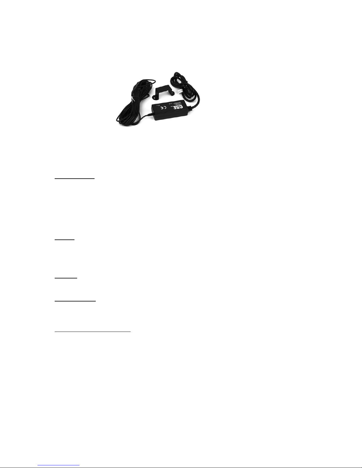
11. Charging power supply
The battery charger is suitable for an input voltage of between 100V and 240V. The
output voltage is 33 V=. The charging current is 1 A.
There are different diagnostic codes if the lift requires charge
Code 1 and 7: When the battery voltage is very low (maybe down to 10%capacity left
in batteries), this fault code will appear. When the lift docks on to charge contacts, the
lift will not drive off the contacts. 1 will flash. Lift will only drive off if battery voltage
has recovered approximately three quarter capacity. Another way of driving off the
contacts is if lift is powered “off” then back “on” but as soon as lift docks on contacts,
process will repeat again. This fault code is linked to fault code 7 but the code 7 is not
usually seen as code 1 takes priority.
Code r: This code will occur when the lift is charging. If the power supply is
disconnected while the lift is charging, the r code will display. A fault with the 33V
power supply where the power supply cannot supply current to charge the batteries
will also show this code.
Code U: This code occurs when the lift has fully charged the batteries and is in
sleeping mode. When the 33V power supply is disconnected, the U code will display.
Code d and H: This code appears if the batteries are low. The main relay on the
board is rated for 24VDC operation so the low voltage will give a false fault condition.
Software priority determines whether d or H are displayed.
Testing the power supply:
Connect the multimeter between the spade of the red wire and the ground. The
voltage raises until 29,5V=. After 5 minutes the voltage it’s 27.5 V=. Make a test ride,
if the voltage drops under 20V= there is a problem with the batteries or the power
supply.
Page 17
16
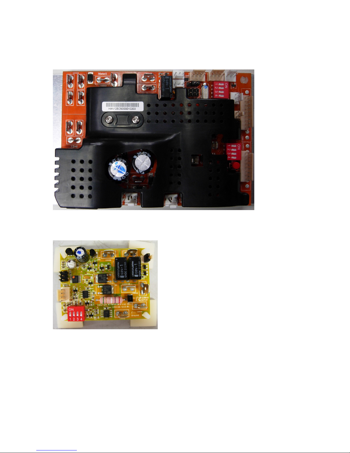
12. Boards
125 Mainboard
126 Powered swivel
126 Powered footrest
Page 18

17
13. Options
The stairlift can be extended with extra powered options:
• Powered swivel chair
• Powered footrest raiser
Logic
The grey communication loom provides a link between the 125 pcb and the 126 pcb.
The 126 connection on the MS125 pcb output is 11,5 volts. Each time a 126 pcb is
connected, the reading will drop by approximately 0.8 volts as communication
between the two pcb’s is established.
The 126 pcb dip switch settings tell the MS125 pcb what powered option is
connected. Each dip switch setting is looking for different parameters to determine
when and where power should be applied to the attached motor.
When the parameters are met, the MS125 pcb passes the battery voltage through
the communication loom to the 126 pcb. The 126 pcb then reduces the output to the
correct voltage for the attached motor to power the option. Depending on which
option is attached, voltage would be applied to the motor for a set time or until the
motor has hit a stop, the 126 pcb has a stall current.
In case of a failure on the communication circuit, the lift runs, but the options don’t
function.
Powered swivel chair
The powered swivel chair swivels at the top and is operated from the toggle. The lift
shall be on the upper end limit switch and the board should detect the charge
voltage. The powered swivel chair can be operated manually in case of emergency.
At the side of the chair is a button for manual override.
Powered footrest raiser
The powered footrest raiser is powered from a button under the armrest. The
powered footrest can be activated all along the track.
Page 19

18
14. Rescuing the user
Instructions for rescuing a user seated on a chair lift of the type Handicare Xclusive
that is still at the top of the stairs.
Check the status of the stairlift via the diagnostic display. Remove faults in the stair
lift that could pose a danger to the user. For example, faults in the footrest safeguard,
in the operation, detection strips or the chair position switch.
Never ride with the user on the lift when a safety measure is switched off.
If it is not possible to remove the fault without danger to the user, first release the
user:
In such case ensure that your are positioned above the user and the chair lift at all
times.
Move the user to safety by turning the chair in the direction of the stairs. Lock the
chair in place. Unfasten the safety belt. The client may now step in the direction of
the stairs and proceed to the floor above.
Remove the fault; if necessary, you may ride the chair lift to the floor level using the
manual hand wheel, for which please refer to the manual.
 Loading...