

Page 1
Page 2
Disclaimer
Welch Allyn reserves the right to make changes in specifications and
other information contained in this document without prior notice, and the
reader should in all cases consult Welch Allyn to determine whether any
such changes have been made. The information in this publication does
not represent a commitment on the part of Welch Allyn.
Welch Allyn shall not be liable for technical or editorial errors or
omissions contained herein; nor for incidental or consequential
damages resulting from the furnishing, performance, or use of this
material.
This document contains proprietary information which is protected by
copyright. All rights are reserved. No part of this document may be
photocopied, reproduced, or translated into another language without the
prior written consent of Welch Allyn, Incorporated.
1999–2000 Welch Allyn Data Collection, Inc. All rights reserved.
Web Address: http://dcd.welchallyn.com
The CE mark on the product indicates that the system has been tested to and
conforms with the provisions noted within the 89/336/EEC Electromagnetic
Compatibility Directive and the 73/23/EEC Low Voltage Directive.
For further information, please contact:
Welch Allyn Ltd.
1st Floor
Dallam Court Dallam Lane
Warrington, Cheshire W A2 7LT
England
Welch Allyn shall not be liable for use of our product with equipment
(i.e., power supplies, personal computers, etc.) that is not CE marked and
does not comply with the Low Voltage Directive.
C.S.A. Statement
This product must be used with a certified Class 2 power
supply or be powered by a certified SEL V (Safety Extra Low
Voltage) output.
Page 3

This device complies with part 15 of the FCC Rules. Operation is subject to the
following two conditions: (1) this device may not cause harmful interference, and
(2) this device must accept any interference received, including interference that
may cause undesired operation.
FCC Class B Compliance Statement
This equipment has been tested and found to comply with the limits for a Class B
digital device pursuant to part 15 of the FCC Rules. These limits are designed to
provide reasonable protection against harmful interference in a residential
installation. This equipment generates, uses, and can radiate radio frequency
energy and, if not installed and used in accordance with the instructions, may
cause harmful interference to radio communications. However, there is no
guarantee that interference will not occur in a particular installation. If this
equipment does cause harmful interference to radio or television reception,
which can be determined by turning the equipment off and on, the user is
encouraged to try to correct the interference by one or more of the following
measures:
• Reorient or relocate the receiving antenna.
• Increase the separation between the equipment and receiver.
• Connect the equipment into an outlet on a circuit different from that
to which the receiver is connected.
• Consult the dealer or an experienced radio or television technician for help.
Caution: Any changes or modifications made to this device that are not
expressly approved by Welch Allyn, Inc. may void the user’s authority to
operate the equipment.
Note: To maintain compliance with FCC Rules and Regulations, cables
connected to this device must be
wire(s) have been grounded (tied) to the connector shell.
Canadian Notice
This equipment does not exceed the Class B limits for radio noise emissions as
described in the Radio Interference Regulations of the Canadian Department of
Communications.
Le present appareil numerique n’emet pas de bruits radioelectriques depassant
les limites applicables aux appareils numeriques de la classe B prescrites dans
le Reglement sur le brouillage radioelectrique edicte par le ministere des
Communications du Canada.
shielded
cables, in which the cable shield
CDRH Laser Safety Statement
This product complies with US DHHS 21 CFR J Part 1040.10. This product is a
CLASS II LASER PRODUCT with a maximum output of 1.0 mW at 670
nanometers and continuous wave.
EN 60825–1 Laser Safety Statement
This product is classified as a CLASS 2 LASER PRODUCT with a maximum
output of 9.0 mW at 670 nanometers per EN 60825–1:1994, Issue 2, June 1997.
Cordless System Manual
Page 4
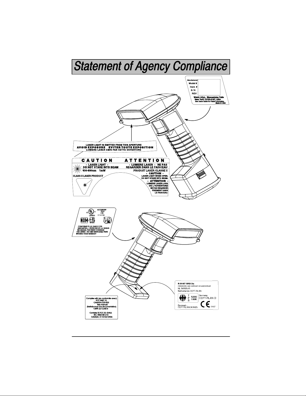
Enlarged Views of Regulatory Labels
MAY 1999
SCANTEAM 5770
5770XX–X
SE1234567
SW REV X.X
Laser Scanner
Only:
Cordless Scanner
Right Side View
(without battery pack)
Cordless Scanner
Left Side View
with
Battery Pack
–B Models:
Cordless System Manual
Page 5

TABLE OF CONTENTS
Section 1 Introduction & Installation
Section Page
Introduction 1–1. . . . . . . . . . . . . . . . . . . . . . . . . . . . . . . . . . . . . . . .
Getting Started
Cordless System: Main Components 1–2. . . . . . . . . . . . . . . . . .
About the Battery Pack 1–3. . . . . . . . . . . . . . . . . . . . . . . . . . . . . .
Charging Your Battery Pack 1–4. . . . . . . . . . . . . . . . . . . . . . . . . .
Setting Up and Connecting the Cordless System 1–5. . . . . . . .
Connecting More Scanners to the System 1–7. . . . . . . . . . . . . .
Beeper and LED Sequences and Meaning 1–8. . . . . . . . . . . . .
Basic Operation of the Cordless System 1–9. . . . . . . . . . . . . . .
System Conditions 1–11. . . . . . . . . . . . . . . . . . . . . . . . . . . . . . . . . .
Communication Between Cordless System and Host 1–13. . . .
Accessories for the Cordless System 1–14. . . . . . . . . . . . . . . . . .
Section 2 Quick Start & Interface Menu
Section Page
Introduction 2–1. . . . . . . . . . . . . . . . . . . . . . . . . . . . . . . . . . . . . . . .
Plug and Play Selections
Industrial Interface: IBM PC 2–2. . . . . . . . . . . . . . . . . . . . . . . . . .
Industrial Interface, Aux Port: RS232 2–2. . . . . . . . . . . . . . . . . .
IBM 468X/9X Ports 5B, 9B, and 17 Interface 2–3. . . . . . . . . . .
Industrial Interface, Aux Port: Wand Emulation 2–4. . . . . . . . . .
Terminal Interface Selections
Supported Terminals 2–5. . . . . . . . . . . . . . . . . . . . . . . . . . . . . . . .
Country Code, Keyboard, & Delays Selections
Keyboard Country Selection 2–7. . . . . . . . . . . . . . . . . . . . . . . . . .
Keyboard Style Selections 2–8. . . . . . . . . . . . . . . . . . . . . . . . . . .
Keyboard Style Modifiers 2–9. . . . . . . . . . . . . . . . . . . . . . . . . . . .
Output Delays Selection 2–10. . . . . . . . . . . . . . . . . . . . . . . . . . . . .
Wand Emulation Selections
Transmission Rate Selection 2–11. . . . . . . . . . . . . . . . . . . . . . . . .
Output Polarity Selection 2–11. . . . . . . . . . . . . . . . . . . . . . . . . . . . .
Cordless System Manual
i
Page 6

Section 2 Quick Start & Interface Menu (continued)
Section Page
Power Settings
Base Low Power Mode 2–12. . . . . . . . . . . . . . . . . . . . . . . . . . . . . .
Battery Conservation Mode 2–12. . . . . . . . . . . . . . . . . . . . . . . . . .
Timeout Selections 2–13. . . . . . . . . . . . . . . . . . . . . . . . . . . . . . . . . .
Reset &Status Check Selections
Reset Factory Settings 2–14. . . . . . . . . . . . . . . . . . . . . . . . . . . . . .
Status Check Selection 2–14. . . . . . . . . . . . . . . . . . . . . . . . . . . . . .
Section 3 Communications Menu
Section Page
Introduction 3–1. . . . . . . . . . . . . . . . . . . . . . . . . . . . . . . . . . . . . . . .
Host Port Communications
Baud Rate Selection 3–2. . . . . . . . . . . . . . . . . . . . . . . . . . . . . . . .
Parity Selection 3–3. . . . . . . . . . . . . . . . . . . . . . . . . . . . . . . . . . . . .
Word Length Data Bits Selection 3–3. . . . . . . . . . . . . . . . . . . . . .
Word Length Stop Bits Selection 3–4. . . . . . . . . . . . . . . . . . . . . .
Serial Wedge Output Selection 3–4. . . . . . . . . . . . . . . . . . . . . . .
Hardware Flow Control Selection 3–4. . . . . . . . . . . . . . . . . . . . .
Host ACK Selection 3–5. . . . . . . . . . . . . . . . . . . . . . . . . . . . . . . . .
Escape Commands 3–5. . . . . . . . . . . . . . . . . . . . . . . . . . . . . . . . .
Auxiliary Port Communications
Baud Rate Selection 3–6. . . . . . . . . . . . . . . . . . . . . . . . . . . . . . . .
Parity Selection 3–7. . . . . . . . . . . . . . . . . . . . . . . . . . . . . . . . . . . . .
Word Length Data Bits Selection 3–7. . . . . . . . . . . . . . . . . . . . . .
Word Length Stop Bits Selection 3–8. . . . . . . . . . . . . . . . . . . . . .
Protocol Selection 3–8. . . . . . . . . . . . . . . . . . . . . . . . . . . . . . . . . . .
Aux Port I.D. Transmit Selection 3–8. . . . . . . . . . . . . . . . . . . . . .
IBM 4683 Async Address Selections 3–9. . . . . . . . . . . . . . . . . .
Hardware Flow Control Selection 3–10. . . . . . . . . . . . . . . . . . . . .
Data Character Selection 3–10. . . . . . . . . . . . . . . . . . . . . . . . . . . .
Aux Prefix / Suffix Selections
Aux Prefix Selection 3–13. . . . . . . . . . . . . . . . . . . . . . . . . . . . . . . . .
Aux Suffix Selection 3–13. . . . . . . . . . . . . . . . . . . . . . . . . . . . . . . . .
Aux Data Formatter Selections
Aux Data Formatter 3–15. . . . . . . . . . . . . . . . . . . . . . . . . . . . . . . . .
Aux Data Formatter Example 3–16. . . . . . . . . . . . . . . . . . . . . . . . .
Aux Format Editor 3–16. . . . . . . . . . . . . . . . . . . . . . . . . . . . . . . . . . .
Require Aux Data Format 3–20. . . . . . . . . . . . . . . . . . . . . . . . . . . .
Alternate Aux Data Formats 3–21. . . . . . . . . . . . . . . . . . . . . . . . . .
ii
Cordless System Manual
Page 7

Section 4 Application Work Groups Menu
Section Page
Introduction 4–1. . . . . . . . . . . . . . . . . . . . . . . . . . . . . . . . . . . . . . . .
Output Selections (User Feedback)
Application Work Group Selection 4–2. . . . . . . . . . . . . . . . . . . . .
Remove Scanner Selection 4–3. . . . . . . . . . . . . . . . . . . . . . . . . .
Beeper Volume Selection 4–3. . . . . . . . . . . . . . . . . . . . . . . . . . . .
Beeper Pitch 4–4. . . . . . . . . . . . . . . . . . . . . . . . . . . . . . . . . . . . . . .
Decode Beep Selection 4–4. . . . . . . . . . . . . . . . . . . . . . . . . . . . . .
Scanner Voting Selection 4–5. . . . . . . . . . . . . . . . . . . . . . . . . . . .
Laser Marker Beam 4–5. . . . . . . . . . . . . . . . . . . . . . . . . . . . . . . . .
AIM I.D. Prefix 4–6. . . . . . . . . . . . . . . . . . . . . . . . . . . . . . . . . . . . . .
Code I.D. Prefix 4–6. . . . . . . . . . . . . . . . . . . . . . . . . . . . . . . . . . . . .
Prefix / Suffix Selections
Prefix/Suffix Description and Examples 4–7. . . . . . . . . . . . . . . .
Prefix Selection 4–10. . . . . . . . . . . . . . . . . . . . . . . . . . . . . . . . . . . . .
Suffix Selection 4–10. . . . . . . . . . . . . . . . . . . . . . . . . . . . . . . . . . . . .
Data Formatter Selections
Data Formatter Selections 4–12. . . . . . . . . . . . . . . . . . . . . . . . . . .
Format Editor Commands 4–13. . . . . . . . . . . . . . . . . . . . . . . . . . . .
Data Formatter 4–16. . . . . . . . . . . . . . . . . . . . . . . . . . . . . . . . . . . . .
Require Data Format 4–16. . . . . . . . . . . . . . . . . . . . . . . . . . . . . . . .
Show Data Formats 4–16. . . . . . . . . . . . . . . . . . . . . . . . . . . . . . . . .
Alternate Data Formats 4–17. . . . . . . . . . . . . . . . . . . . . . . . . . . . . .
Cordless System Manual
iii
Page 8

Section 5 Symbology Menu
Section Page
Introduction 5–1. . . . . . . . . . . . . . . . . . . . . . . . . . . . . . . . . . . . . . . .
Industrial Symbology Selections
Codabar Selection 5–2. . . . . . . . . . . . . . . . . . . . . . . . . . . . . . . . . .
Code 39 Selection 5–4. . . . . . . . . . . . . . . . . . . . . . . . . . . . . . . . . .
Code 93 Selection 5–6. . . . . . . . . . . . . . . . . . . . . . . . . . . . . . . . . .
Interleaved 2 of 5 Selection 5–7. . . . . . . . . . . . . . . . . . . . . . . . . .
Code 2 of 5 Selection 5–8. . . . . . . . . . . . . . . . . . . . . . . . . . . . . . . .
Matrix 2 of 5 Selection 5–8. . . . . . . . . . . . . . . . . . . . . . . . . . . . . . .
Code 11 Selection 5–9. . . . . . . . . . . . . . . . . . . . . . . . . . . . . . . . . .
Code 128 Selection 5–10. . . . . . . . . . . . . . . . . . . . . . . . . . . . . . . . .
Telepen Selection 5–11. . . . . . . . . . . . . . . . . . . . . . . . . . . . . . . . . . .
Retail Symbology Selections
EAN / JAN 8 / 13 Selection 5–12. . . . . . . . . . . . . . . . . . . . . . . . . . .
UPC A Selection 5–13. . . . . . . . . . . . . . . . . . . . . . . . . . . . . . . . . . . .
UPC E0 Selection 5–14. . . . . . . . . . . . . . . . . . . . . . . . . . . . . . . . . . .
UPC E1 Selection 5–14. . . . . . . . . . . . . . . . . . . . . . . . . . . . . . . . . . .
EAN / UPC Addenda Selection 5–15. . . . . . . . . . . . . . . . . . . . . . .
Section 6 Supported Interface Keys
Section Page
Keyboard Function Relationships 6–1. . . . . . . . . . . . . . . . . . . . .
Supported Interface Keys 6–2. . . . . . . . . . . . . . . . . . . . . . . . . . . .
iv
Cordless System Manual
Page 9

Section 7 Product Specifications and Pinouts
Section Page
Specifications
SCANTEAM 2070 Cordless Base Specifications 7–1. . . . . . . .
Radio Specifications 7–1. . . . . . . . . . . . . . . . . . . . . . . . . . . . . . . . .
SCANTEAM 3470 Cordless CCD Scanner Specifications 7–2
SCANTEAM 5770 Cordless Laser Scanner Specifications 7–3
Regulatory and Safety Agency Approvals 7–5. . . . . . . . . . . . . .
Patents 7–5. . . . . . . . . . . . . . . . . . . . . . . . . . . . . . . . . . . . . . . . . . . .
Connectors & Pinouts
Auxiliary RS-232 / Wand Emulation Connector 7–6. . . . . . . . . .
Keyboard / Terminal and RS-232 (Host Port) Connector 7–7. .
External Power Connector 7–7. . . . . . . . . . . . . . . . . . . . . . . . . . .
Dimensions
Cordless Base Dimensions 7–8. . . . . . . . . . . . . . . . . . . . . . . . . . .
Cordless Scanner Dimensions 7–9. . . . . . . . . . . . . . . . . . . . . . . .
Scan Maps
Typical Performance at 205for SCANTEAM 3470LR 7–10. . .
Typical Performance at 205 for SCANTEAM 3470HD 7–10. . .
Typical Performance at 205 for SCANTEAM 5770STD 7–11. .
Typical Performance at 205 for SCANTEAM 5770HD 7–11. . .
Typical Performance at 205 for SCANTEAM 5770LR 7–12. . .
Typical Performance at 205 for SCANTEAM 5770HV 7–13. . .
Section 8 Maintenance and Troubleshooting
Section Page
Maintenance 8–1. . . . . . . . . . . . . . . . . . . . . . . . . . . . . . . . . . . . . . .
Troubleshooting 8–3. . . . . . . . . . . . . . . . . . . . . . . . . . . . . . . . . . . .
Section 9 Customer Support
Section Page
Obtaining Factory Service 9–1. . . . . . . . . . . . . . . . . . . . . . . . . . . .
Technical Support 9–2. . . . . . . . . . . . . . . . . . . . . . . . . . . . . . . . . . .
Limited Warranty 9–3. . . . . . . . . . . . . . . . . . . . . . . . . . . . . . . . . . . .
Limited Warranty Durations 9–3. . . . . . . . . . . . . . . . . . . . . . . . . .
Default Charts
Programming Chart (inside back cover)
Sample Bar Codes (back cover)
Cordless System Manual
v
Page 10

vi
Cordless System Manual
Page 11

Section 1 Introduction & Installation
Introduction
The Cordless Scanning System consists of the SCANTEAM 2070 Base unit
and at least one SCANTEAM 3470 Cordless CCD or SCANTEAM 5770
Cordless Laser Scanner. Up to nine scanners may be associated with one
base. Each cordless scanner has a removable, rechargeable battery pack and
provides real time decoding within a 50 foot (15.24 meter) radius of the base
unit.
The Cordless System is an economical, durable solution for a wide variety of
portable data collection applications. The Cordless System features:
• a tough, ergonomic thermoplastic housing for comfort and durability .
• recognition and decoding of the most popular, industry-standard bar
code symbologies.
• scanner coverage of up to 7854 square feet (730 square meters) in open
air environments.
• a wide range of interfaces that are compatible with many POS, keyboard
wedge, and RS-232 terminals.
• visible and audible feedback for confirmation of a successful decode.
• a rechargeable battery designed to operate through a whole work day .
This System Manual contains information to help you set up, operate, and
program the Cordless System. Product specifications, connector pinouts, scan
maps, a troubleshooting guide, and customer information are also provided.
The Cordless System can be programmed for many communications
parameters and input/output protocols compatible to the host, as well as
advanced data editing and formatting. Programming is accomplished by using
the single programming bar codes in this manual (Sections 2 through 4).
This section contains the following “Getting Started” information:
• Cordless System Main Components
• Battery Pack and Charging Information
• Cordless System Set Up and Connection
• Beeper and LED Sequences and Meaning
• Basic Operation of the Cordless System
• Communication Between the Cordless System and the Host
• Accessories for the Cordless System
A 50 foot radius is obtained under optimal, “open air” conditions. Signals between the
base and its scanners need a clear path to communicate, free from RF interference.
Cordless System Manual
1–1
Page 12
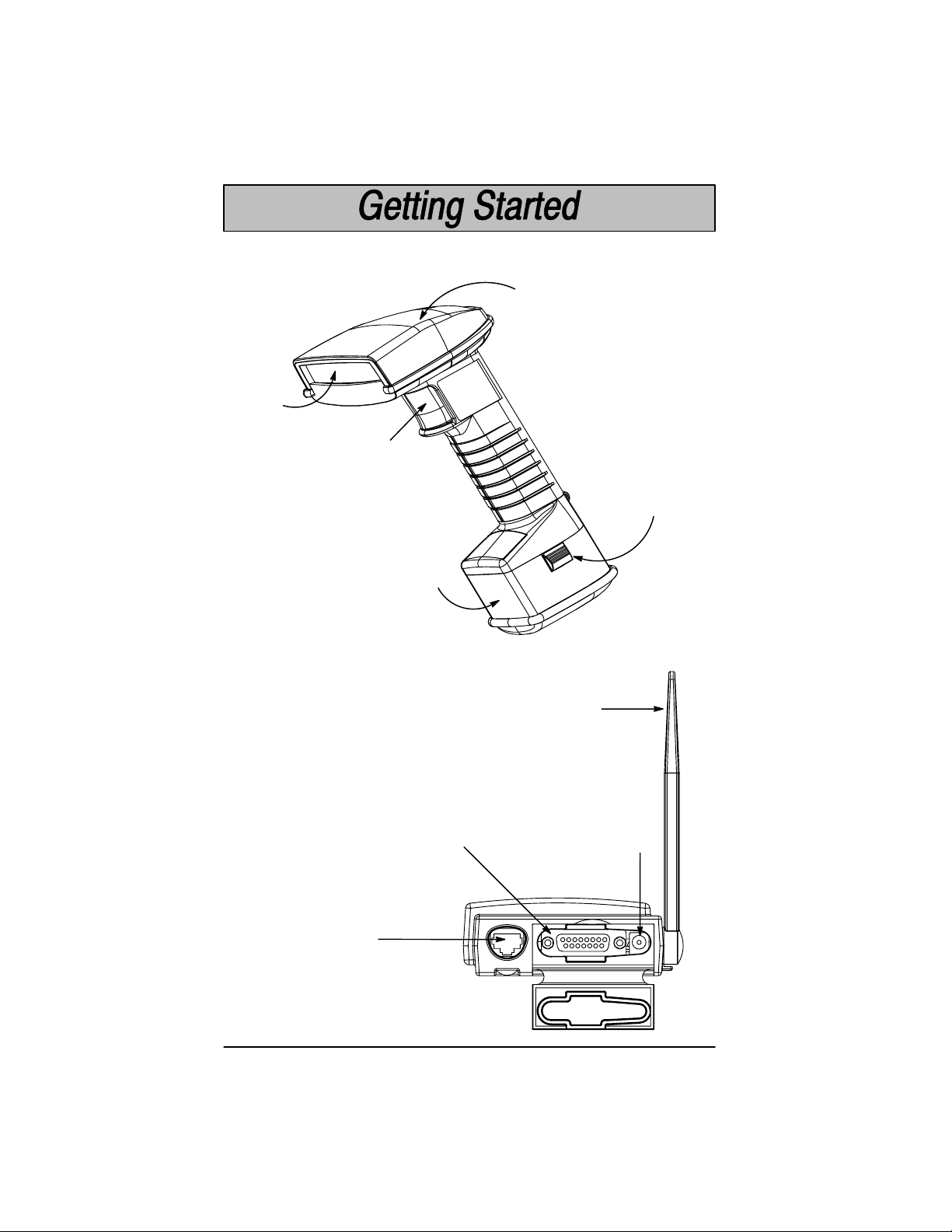
Cordless System: Main Components
Scan
Window
Trigger
Battery
Pack
Indicator
LEDs
Cordless Scanner
Left Side View
(with battery pack)
Battery
Pack Clip
(2 Places)
Cordless Base
Back View
Aux RS-232, Service Port,
and Wand Emulation
Output Connector
1–2
Keyboard/Terminal
and RS-232 Connector
(Host Port)
Cordless System Manual
Antenna
External Power
Connector
Page 13

About the Battery Pack
Power is supplied to the Cordless Scanner by a rechargeable
battery pack that snaps onto the bottom of the scanner. Each
scanner is shipped with a battery pack.
Specifications, page 7–4, for technical specifications.)
Order backup battery pack(s) or replacement
batteries from your distributor.
North American Charging Information
The battery pack is designed to plug into any two prong North American AC
power outlet (1 10/120 Volt) for direct charging. You need no additional
equipment and you can recharge the pack virtually anywhere.
Worldwide Charging Information
Since the battery pack is rated for both 1 10/120 volt 60 Hz and 230/240 volt 50
Hz applications, it may be charged worldwide. To accommodate the wide
variety of electrical outlets internationally , a custom charge strip is required to
charge the batteries.
WARNING: When the charge strip is used in 240V applications, only use battery
34/5770/NIMH/S. Do not attempt to charge battery part numbers:
34/5770/NICAD, 34/5770/NIMH, 34/5770/NIMH/F, or 34/5770/NICAD/F.
Battery Pack Recommendations
• Batteries are shipped uncharged and need to be fully charged and
discharged two or more times to be fully conditioned.
• Charge the battery for 24 hours for at least the first two times to fully
condition the battery.
• Charge the battery pack immediately before use or at least within a
couple of days of use.
• Remove the battery pack from the power outlet or charge strip within 24
hours after charging is completed. Avoid extended overcharging; do not
leave the battery charging for more than two days.
• Fully discharge the battery pack on a periodic basis by leaving the battery
pack attached to the scanner overnight. (Make sure all idle modes are
disabled for this procedure.)
• Avoid using the battery pack in extreme temperatures.
• Do not disassemble the battery pack. There are no user-serviceable
parts in the battery pack.
(See Battery
Cordless System Manual
1–3
Page 14
Char
Proper Disposal of the Battery Pack
When the battery pack has reached the end of its useful life,
the batteries should be disposed of by a qualified recycler or
hazardous materials handler. Do not incinerate the battery
pack or dispose of the battery pack with general waste
materials. Contact the Product Service Department (see
page 9–1) for recycling or disposal information.
ging Your Battery Pack
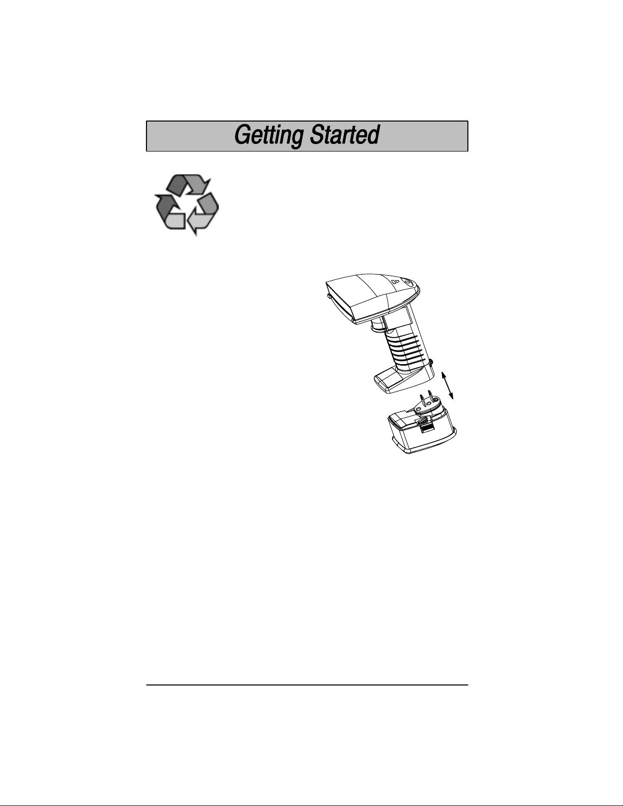
Charge the Battery Pack by following the steps shown below:
➊ Fully charge the battery (see page
1–3). Plug the battery pack directly
into any common 120 Volt AC outlet
in North America. If outside North
America, use the custom charge
strip.
Cordless
Scanner
➋ The LED on the bottom of the battery pack lights
red when the unit is charging; it shows green
when it is fully charged and ready to use.
Note: It is important that you charge the battery for
24 hours prior to the first use. No damage
occurs if this is not done, but the battery
capacity will not be 100%.
Recharge Time
4 hours at any voltage at 20C (68F).
:
Rechargeable
Battery Pack
➌ After the battery pack is fully charged, attach it to the Cordless Scanner by
pressing the pack firmly (align the prongs on the pack with the mating
receptacles) in the base of the scanner until the release buttons click, holding
the pack firmly in place.
Cordless Scanner, you will hear a single beep.)
(When you attach a charged battery pack to the
➍ If you haven’t set up your Cordless System, turn to the next page for
instructions.
When the battery pack needs recharging, the yellow LED on top of the scanner
pulses in short, continuous blinks and the scanner won’t beep when you pull
the trigger. If the LED stops flashing when the temperature lowers or you do
not use the battery pack for some time, you still need to charge the battery
pack to avoid damaging the battery pack or causing scanner memory loss.
1–4
Cordless System Manual
Page 15

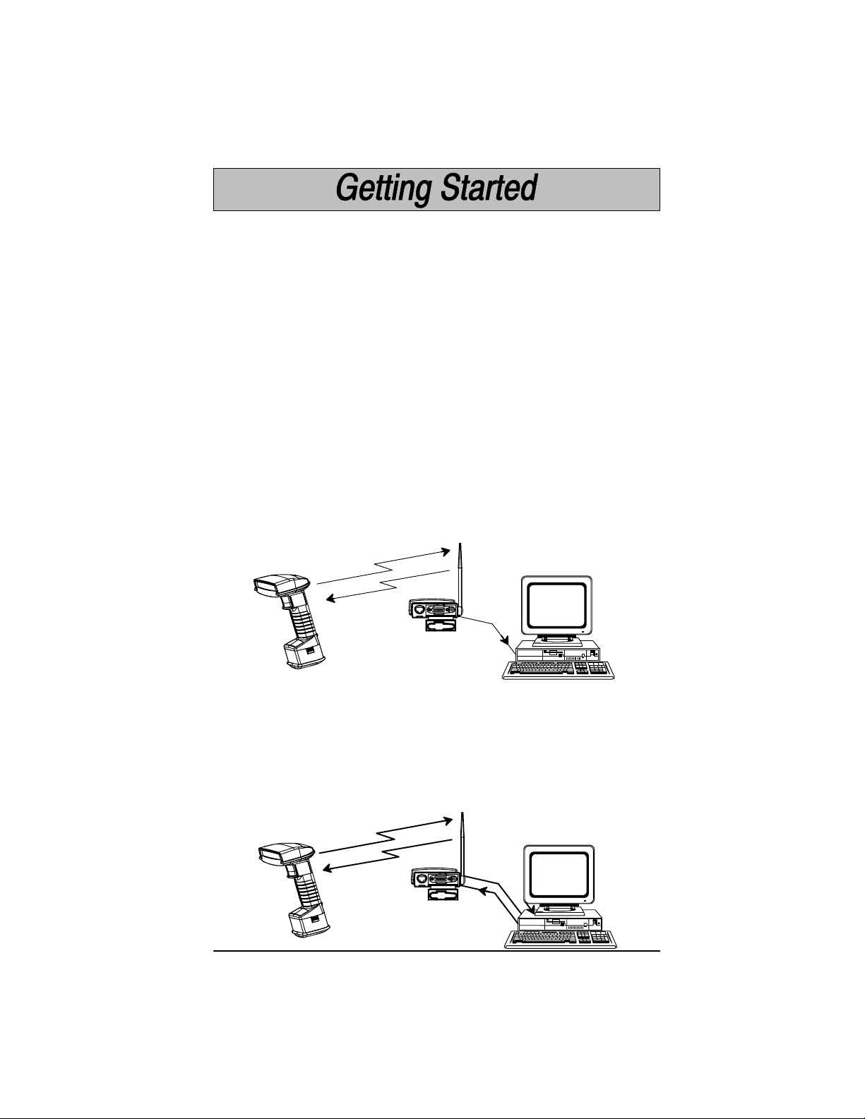
Setting Up and Connecting the Cordless System
Install the base and Cordless Scanner by following the steps shown below:
Important: Make sure the Cordless Scanner’s battery pack has been fully
charged. See page 1–4 for charging instructions.
➊ Turn off the power to the host system.
➋ Connect the interface cable to the base and to the terminal/computer (steps
1–3, shown in the illustration below). Depending on your application, the
interface cable you need may be different than the one shown below .
Keyboard Wedge Interface
Example
Terminal
(host system)
3
Cordless
Base
1
Disconnect
2
(Cable, Keyboard, and Terminal may vary.)
Note: For optimal coverage, place the base and its antenna as far away from
other sources of RF interference, with a clear transmitting path to the scanner(s).
The base can be mounted on a wall or a ceiling. Try to place the base so that
the antenna is in a vertical (straight up and down) position whenever possible.
An extra Base Association Bar Code is provided in case the base is mounted
where the label might be difficult to scan (step 4 on the next page describes the
Association process).
In an RS-232 configuration (see the illustration on the next page), connect your
interface cable between the base unit (step 1 in the illustration) and the host
system (2). You also need to use an external power supply (3). Contact your
distributor for more information on ordering power supplies or RS-232 cables,
including a “Y” extension power cable to mount the base for best RF coverage.
Cordless System Manual
1–5
Page 16
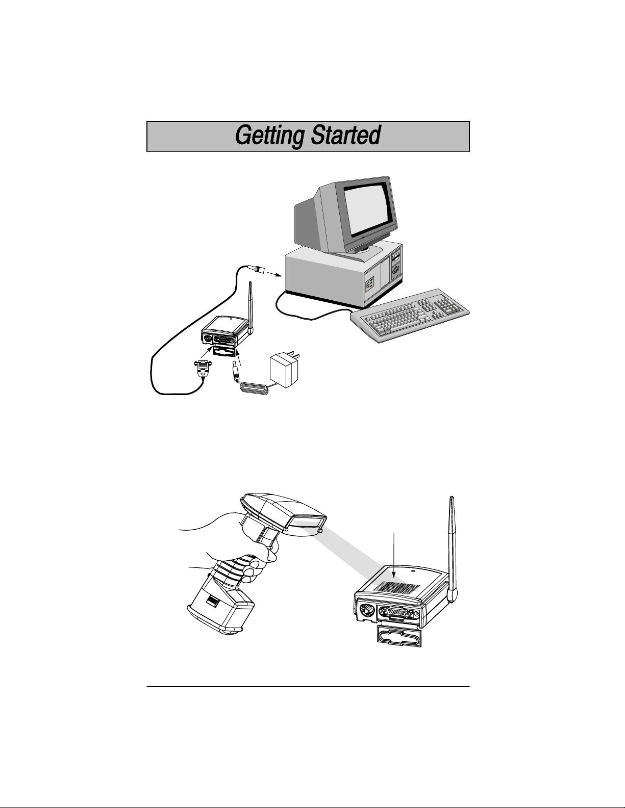
Setting Up and Connecting the Cordless System, continued
RS-232 Interface Example
2
Cordless
Base
1
3
Power
Supply
Terminal
(host system)
(Cable, Keyboard, and Terminal may vary.)
➌ Turn on the power to the host system. Verify that the base is on; the green
LED on top of the unit should blink. (The base does not have a beeper.)
➍ Using the Cordless Scanner, scan the Association Bar Code (the bar code
label on the top of the base) to link that scanner to the base (see the
illustration shown below).
Cordless CCD or
Laser Scanner
Association
Bar Code
Cordless
Base
Two quick beeps followed by clicking, then a single beep. This indicates a “good”
association. The scanner is in communication with the base.
1–6
Cordless System Manual
Page 17

Setting Up and Connecting the Cordless System, continued
Note: After association, if the battery pack is removed from the scanner and
replaced, the scanner automatically reassociates to the base if the base has
remained powered up. In this case, the scanner beeps when a charged battery
pack is installed, then beeps a second time after full association, about five to ten
seconds later.
After your Cordless Scanner has been associated with its base unit:
➎ Program your Cordless System to work with your terminal or computer by
scanning the Terminal Setup Codes. Use the Supported Terminal list
(Pages 2–5 to 2–6) to scan your terminal’s Terminal ID.
With Plug and Play programming, you scan
Cordless System to work with a designated interface, including any required
prefixes and suffixes.
only
one bar code to program the
➏ To determine if your Cordless System is set up correctly, scan one of the
sample bar codes on the back cover of this manual.
Connecting More Scanners to the System
Up to nine Cordless Scanners may be associated with one base unit . Add more
Cordless Scanners to a base unit by following the steps shown below:
➊ Make sure the Cordless Scanner’s battery pack has been fully charged.
➋ Scan the Association Bar Code (the bar code label on the top of the base)
to link each scanner to the base.
The base stores a unique I.D. for each scanner (up to nine) to identify the scanner
during data communication. Two beeps followed by clicking, then a single beep
from the scanner indicates a “good” association. The base rejects a tenth
Cordless Scanner trying to link to its network, sending the scanner an error
command. (A rejected scanner beeps three times, indicating an unsuccessful
association.)
Note: When you associate more scanners with the base, you don’t have to
program your Cordless System to communicate with your terminal or computer
if you’ve already completed step 5, above.
within a 50 foot (15.24 meter) radius of the base, in an open air environment
Cordless System Manual
1–7
Page 18

Beeper and LED Sequences and Meaning
on
on
on
The base contains a green LED that indicates the status of the unit and verification
of its communication with the host system. The Cordless Scanner contains a
beeper and two LEDs on the top of the unit (green and yellow) to indicate its power
up, communication, and battery pack status. The tables below list the indication
and meaning of the beeps and LED illumination for the base and Cordless
Scanner.
Base LED Indicati
Sequence Meaning
LED on continuously Power on, system idle
LED blinks, long duration Power on, diagnostic error
LED blinks, short duration Receiving data from scanner, host, or aux port
LED blinks, four long pulses Communication error detected
Scanner LED Indicati
Sequence Meaning
Green LED on Trigger pulled, out of range
Green LED on, 2 seconds Successful decode and communication
Green LED blinks, Successful decode with unsuccessful
2 seconds communication, or unsuccessful clear to scanner
Green LED on, 5 seconds Enter/exit programming mode, successful
Green LED blinks, Unsuccessful parameter change in programming
5 seconds mode
Yellow LED on Scanning, trigger pulled (in or out of range)
Yellow LED blinks Low battery (trigger pulled)
parameter change in programming mode
Scanner Beep Indicati
Sequence Meaning
No beep No scanning, scanning, or low battery (trigger pulled)
1 beep Successful decode and communication
Clicking, then
1 beep Successful reassociation
Clicking only Unsuccessful reassociation
2 beeps, clicks,
then1 beep Successful association to base
3 beeps – Unsuccessful association to base (10th scanner), out of
same tone range, or no network
3 beeps – Enter/exit programming mode or successful association
2 high and to base. Successful or unsuccessful parameter change
1 low tone in programming mode.
4 beeps – Communication error: successful decode with possible
low, high, unsuccessful communication to base. Check host to
low, high tones determine if data arrived properly .
1–8
Cordless System Manual
Page 19
Basic Operation of the Cordless System
The following system block diagrams (on this and the following page) illustrate
the basic operating components of the Cordless System.
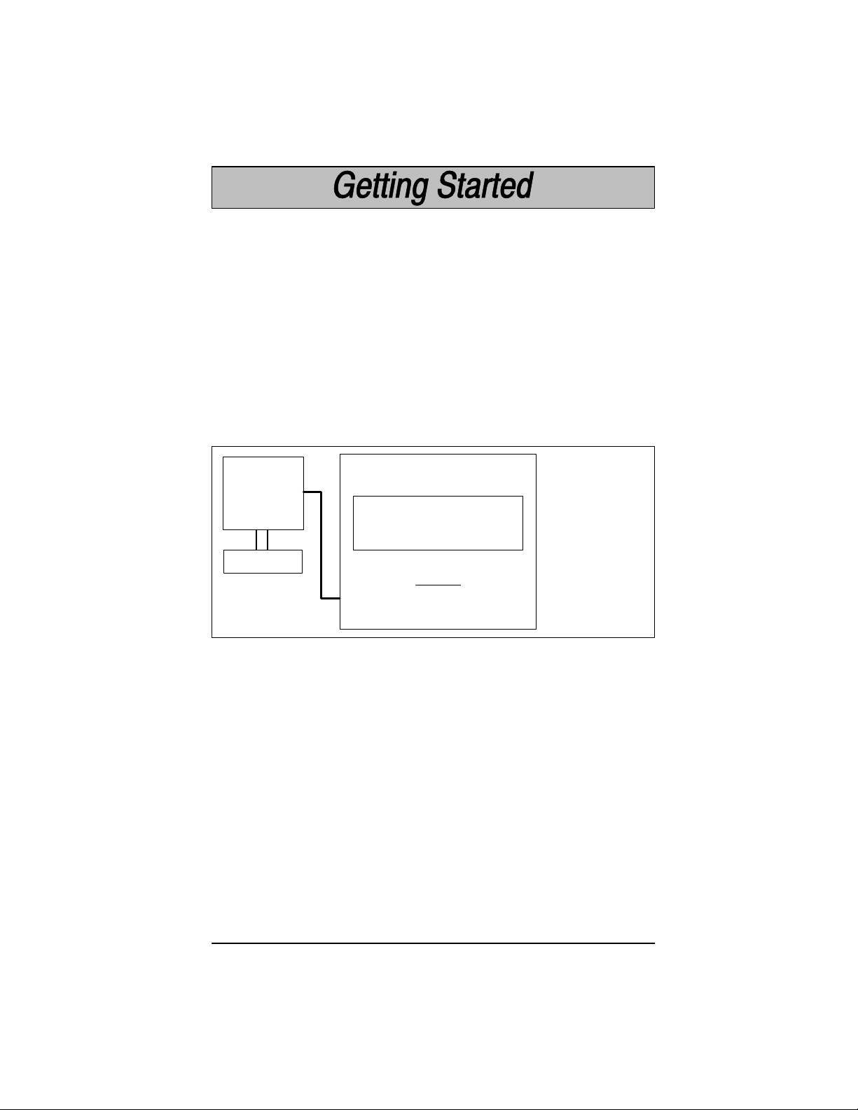
Cordless Base
The Cordless Base provides the link between the Cordless Scanner and the host
system. The base contains a control/interface assembly and an RF
communication module. The RF communication module performs the data
exchange between the Cordless Scanner and the control/interface assembly.
The control assembly coordinates the central interface activities including:
transmitting/receiving commands and data to/from the host system, performing
software activities (parameter menuing, visual indicator support, power-on
diagnostics), and data translation required for the host system.
Cordless Base
Control/Interface Assembly
RF Module
international
(Base Circuit Board)
Control
User I/O
Host I/O
Base Housing
Menu I/O
Multipoint
Antenna
LED
I/O Ports
RF Host
Power Aux
RF (Radio Frequency) Module Operation
The Cordless System uses a state of the art radio to transmit and receive data
between the scanner and the base. Designed for point-to-point and multipoint
to single point applications, the radio transmits data at a rate of 1 megabit per
second (MBPS) in a half duplex (2 way) communications mode. The radio
operates using a license free, low power, 2.4 GHz spread spectrum (frequency
hopping) technique. This transmission technique, which sends relatively small
data packets at a fast data rate over a radio signal with randomly changing
frequencies, makes the Cordless System highly responsive to a wide variety of
data collection applications and resistant to noisy RF environments.
The RF radio used in the Cordless System has been tested and approved as
complying with the two leading standards-setting organizations that serve as
regulatory models for compliance in most countries. In North America, the radio
is approved under the standards in FCC B Part 15.249 regulations and, in
Europe, under the standards in ETS 300 328 regulations.
(See page 7–5 for a
chart of regulatory and safety agency approvals.)
Cordless System Manual
1–9
Page 20
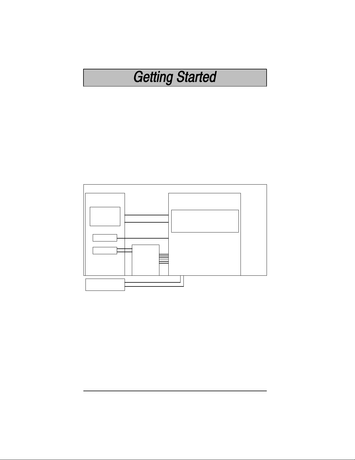
Cordless Scanner
The Cordless Scanner enables bar code scanning with non-contact CCD or
Laser input devices, real time decoding, and host connectivity within a 50 foot
(15.24 meter) radius of the base unit. It provides the initial bar code data
acquisition function and communicates to the base. The scanner is comprised
of a CCD or laser scan engine, a decode/control assembly, and an RF
communication module.
The scan engine performs the bar code image illumination and detection. The
decode/control assembly coordinates the central communication activities
including: capturing and decoding the bar code image data, performing software
activities (parameter menuing, visual indicator support, low battery indication),
and data translation required for the host system. The RF communication
module performs the data exchange between the scanner and the base.
Cordless Scanner
Scanner Assembly
Engine
Assembly
Scan
Engine
(CCD or Laser)
HHLC I/O
Decode/Control Assembly
(Handle Board)
Engine Port
Control
Trig/Decode
Menu I/O
Power Mgmt
Trigger
Handle
Housing
Beeper
Antenna
Engine Hsg
Window/Lt Pipe
Battery Pack
(1.2 mAh)
A 50 foot (minimum) radius is maintained in most environments. For optimal
performance, signals between the base and its scanners need a clear path to
communicate, free from RF interference.
1–10
RF Module
Cordless System Manual
Beeper Port
RF Port
Download Port
Battery Port
Page 21

System Conditions
The components of the Cordless System interact in specific ways as you
associate one or more scanners to a base, as you move a scanner out of range,
bring a scanner back in range, replace a scanner battery pack, or swap scanners
between two Cordless Systems. The following information explains the
Cordless System operating conditions.
Association Process
After you scan the association label, the base synchronizes radio parameters
and the work group parameter table in the scanner. The work group table is
uploaded during the clicking sequence. Two beeps, clicking, then a single beep
indicates the process is complete. The base blinks while it is sending the table
to the scanner. Until the table is uploaded, scanning and data transmission is
interrupted. If the base is off or not working properly , the scanner emits an error
(triple) beep after trying for 30 seconds to associate to the base.
The work group table is also uploaded any time the base believes a previously
associated scanner wishes to join the network. A scanner always tries to join the
last base it was associated to, even if the scanner has been without power for
several days. The base allows a scanner to associate as long as there are fewer
than nine scanners actively associated to the base.
Scanner is Out of Range
The Cordless Scanner is always in communication with its base, even when it
is not transmitting bar code data. Whenever the scanner can’t communicate with
the base for a three second interval, it is out of range. If the trigger is pulled while
the scanner is out of range, the green and yellow LEDs illuminate. When you
scan a bar code, the scanner issues 3 beeps and does not try to send data to the
base.
Note: While the scanner is out of range, it consumes more power searching for
the base continuously. To conserve battery power, store the scanner with the
battery pack removed, or program it for Battery Conservation mode (see page
2–12).
Scanner is Moved Back Into Range
The scanner silently rejoins (no beep after connecting and synchronizing with the
base) if the scanner has not been reset (battery pack disconnected and
reconnected), no menu codes have been scanned by other scanners in the work
group, or the base has not been reset (see Base Reset Conditions, next page).
Any one of these three conditions can cause the scanner to go through a
reassociation process (definition on the next page) when it is moved back in
range. If the scanner reassociates, you will hear a single beep when the
reassociation process (uploading of the parameter table) is complete.
If you believe you are in range and are still hearing a triple (error) beep, you may
have been removed from off the base’s network. Try scanning the association
label or reset scanner by removing and reinserting the battery .
Cordless System Manual
1–11
Page 22

Replacing Battery Pack While Associated
When you insert the battery pack, the scanner beeps, followed by clicking.
During this period the work group parameter table is uploaded to the scanner
from the base. Scanning and data transmission is interrupted. When the
scanner emits a second beep, you may scan again. If you don’t receive a second
beep, the table was not transferred successfully either because the scanner was
out of range or all of the data was not received. Scan the association label again.
Moving Scanners From One Base to Another
You may transfer a scanner between base networks by scanning a new base
association label. Scanners can only be associated to one base at a time. Once
a scanner has been associated to a base, it tries to stay associated to that base
until a new base association label has been scanned. The new base adds a
scanner to its association list as long as fewer than nine scanners are in its
network. If a base has nine scanners in its network, you need to disassociate
one scanner before adding another (see next section).
Swapping Scanners Between Two Systems with Nine Scanners on Each
You may use the Remove Scanner Selection (page 4–3) to disassociate any
scanner and then add a new scanner by scanning the association label with the
new scanner. If you cannot scan the disassociation label because the scanner
you are trying to disassociate was damaged, remove power from that scanner
and it automatically disassociates in approximately three seconds.
Glossary
Base Reset Conditions
The base resets when base power is lost or when a diagnostic problem is
sensed. In either case, the scanners automatically reassociate, if they are within
range.
Reassociation
The process of uploading the work group parameter table from the base is called
“reassociation.” During reassociation, the scanner clicks, then beeps once.
Reassociation is done automatically , without having to scan an association label.
Association List
The base keeps an association list of up to nine entries. This list maintains the
associated scanners’ radio serial numbers and dynamic addresses. New
dynamic addresses are assigned to the scanners each time a Base Reset
occurs. This helps the Cordless System track the status of the different scanners
in its network during the association and reassociation process.
1–12
Cordless System Manual
Page 23
Communication Between the Cordless System and the Host
The Cordless Scanner provides immediate feedback in the form of a “good read”
indication (a green LED on the scanner and an audible beep) after a bar code
is scanned correctly and the base has acknowledged receiving the data. The
Cordless System also provides two way communication between the Scanner
and the base or host system.
When data is scanned, the data is sent to the host system via the base unit.
Confirmation from the host system or the base indicates that the data sent was
received by the host. The Cordless Scanner recognizes two forms of host
confirmation: data acknowledgement (ACK) from the base unit or an “ACK” from
the host system. If it can’t be determined that the data has been properly sent
to the host system, the scanner issues 4 beeps (low, high, low , high tones). You
must then check to see if the scanned data was received by the host system.
Acknowledgement from the Base
If the Cordless System is configured for a keyboard wedge host interface, a
signal (ACK) is sent from the base confirming that the data was received and is
being sent on to the host system. (Since keyboard wedge interfaces cannot
provide bi-directional communications, they do not permit host confirmation.)
1) Good Read
2) ACK
from
Base
3)
*
* Base sends data to Host after ACK is sent to Scanner
Acknowledgement from the Host System
Host system confirmation may be implemented with a bi-directional interface like
Host RS-232. In this configuration, when the base unit receives the scanned
data from the scanner and forwards it to the host, the Cordless System waits for
a signal from the host that it received the data. (For information on enabling this
feature and using Host Escape commands, see Host Ack Selection, page 3–5).
1) Good Read
2) Data
4) ACK
from
Host
(via base)
Cordless System Manual
to Host
3) ACK
1–13
Page 24

Accessories for the Cordless System
Several accessories are available for the Cordless System. Contact your
distributor for more information or to order accessories.
Battery Packs
The battery pack for the cordless scanner is a rechargeable Nickel Metal Hydride
(NiMH) pack that, when fully charged, provides up to 18,000 scans or 28 hours
of continuous use. The unique design of the battery allows the battery pack to
be directly charged in a two prong 120 volt wall outlet commonly used in North
America.
For other parts of the world with different voltages and frequencies, the universal
charge strip is needed. While the battery pack may be charged directly with 240
volts, the universal charge strips provide the method to physically adapt to the
various power plug and socket configurations.
Each scanner is shipped with one battery pack. Order back up batteries or
replacement batteries separately.
Charge Strips
To charge more than one battery pack at one time, charge strips are available.
The charge strips are offered in two or six outlet configurations and may be
conveniently wall mounted or placed on flat surfaces. The charge strip uses a
standard PC (IEC 320) grounded power cord between the charge strip and the
electrical AC outlet.
Note: International versions of the power cords are provided by Welch
Allyn’s country partners or may be purchased from your local PC supplier.
Welch Allyn does not supply these power cords.
Belt Holster
The belt holster holds the Cordless Scanner when not in use. The belt holster
consists of a foam covered wire frame clasped to an adjustable nylon web belt
designed to be worn around the waist.
Wall Mount Kit (Standard)
The standard wall mount holder stores the Cordless Scanner on a vertical
surface for convenient access. The scanner easily slides between two
rubberized fingers that hold the scanner when it is not in use.
Wall Mount Kit (Industrial)
Similar to the standard wall mount holder, the rubberized fingers on the industrial
wall mount holder are smaller to maintain a firm grasp on the scanner under
jolting and jarring conditions, such as those expected in fork lift applications.
Head Cover
The head cover features a “D” ring to attach to a tool balancer to suspend the
scanner rather than putting it down.
Base Wall Mount Bracket
For applications where ST2070 base needs to be firmly mounted to a wall. The
bracket slides into the molded feature on the back side of the base.
Visual Menu
Visual Menu is a software configuration tool that provides the ability to configure
the Cordless System by connecting the base unit to the COM port of a PC. Visual
Menu allows you to download firmware upgrades, change programmed
parameters, and create and print programming bar codes.
1–14
Cordless System Manual
Page 25

Section 2 Quick Start & Interface Menu
Introduction
Use this section to program the Cordless System to work with your terminal or
computer (host system).
This programming section contains the following menu selections:
• Plug and Play
• Terminal Interface
• Country Code
• Keyboard
• Output Delays
• Wand Emulation
• Power Settings
• Reset Factory Settings and Status Check
All operating parameters are stored in non-volatile memory resident in the
Cordless System, where they are permanently retained in the event of a power
interruption. When you receive your Cordless System, certain operating
parameters have already been set. These are the factory defaults, indicated by
the symbol “✱” on the programming pages (beneath the default programming bar
code). Default Charts that list all the factory settings may be found near the end
of this System Manual.
A Programming Chart (found on the inside back cover of this manual) contains
alphanumeric bar codes for setting additional programming options, such as the
digits representing Symbology Message Length. The chart explains how and
when to use the alphanumeric bar codes.
Note: After scanning the following menu selections, there will be a pause (up
to 20 seconds) while the Base unit processes and uploads the new menuing
information to its parameter tables:
Plug and Play Selections (on the next two pages)
Factory Default Settings: ALL Application Groups (last page, Section 2)
Application Work Group Selections (Section 4)
A Sample Bar Codes page (located on the back cover of this manual) provides
bar code symbols you may scan to verify that your Cordless System has been
programmed correctly and is communicating with your host system.
Cordless System Manual
2–1
Page 26
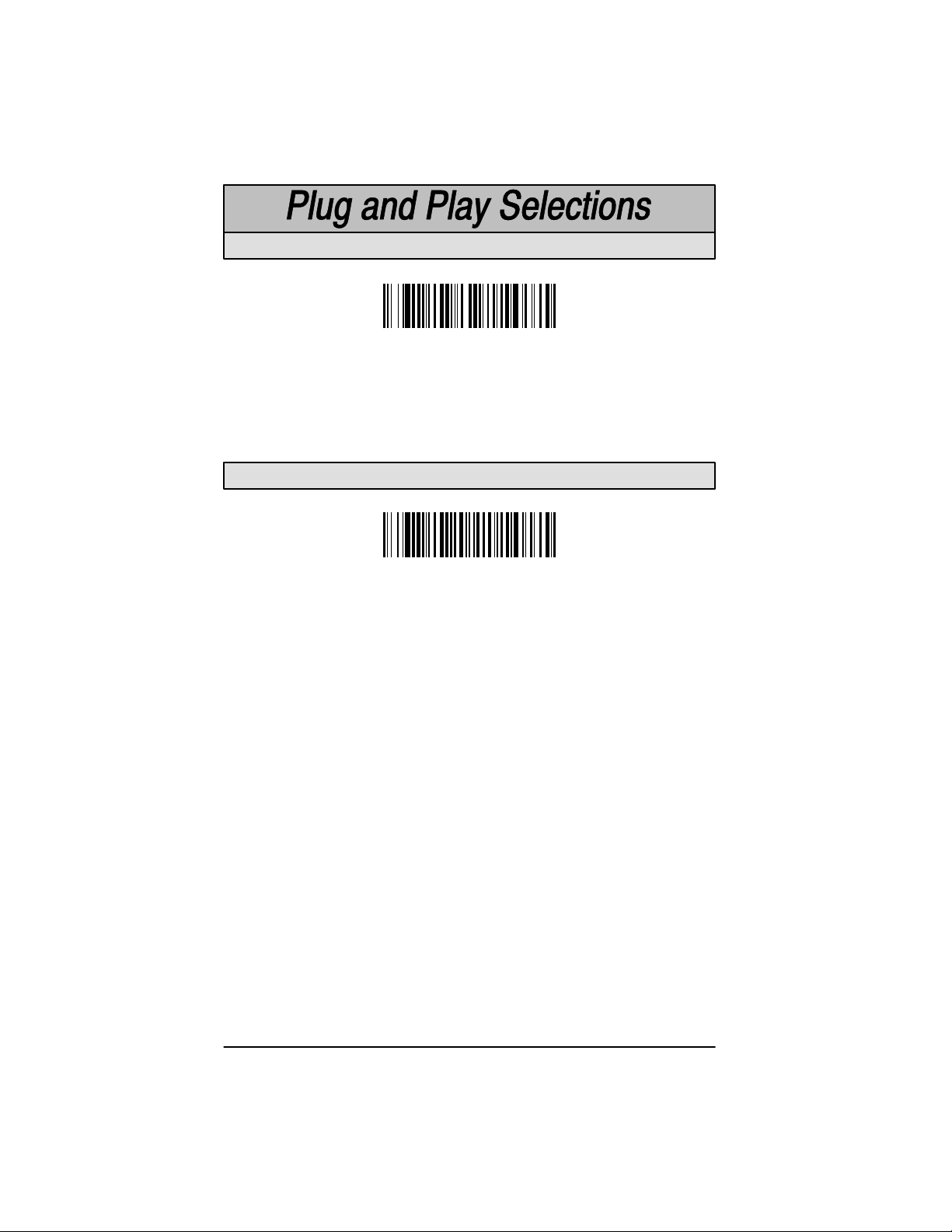
Industrial Inter face: IBM PC
IBM PC AT and Compatibles Interface
(also PS/2 30-286, 50, 55SX, 60, 70, 70-061, 70-121, 80)
(Factory Default)
The bar code above also programs a carriage return (CR) suffix.
Industrial Interface, Aux Port: RS-232
RS-232 Interface
The bar code above also programs the following parameters:
Programmable Option Setting
Baud Rate 38,400 bits per second
Parity None
Data Format 8 data bits, 1 stop bit
Prefix None
Suffix Carriage Return (CR)
Note: Plug and Play menu codes will default all settings before programming
the interface.
2–2
Cordless System Manual
Page 27

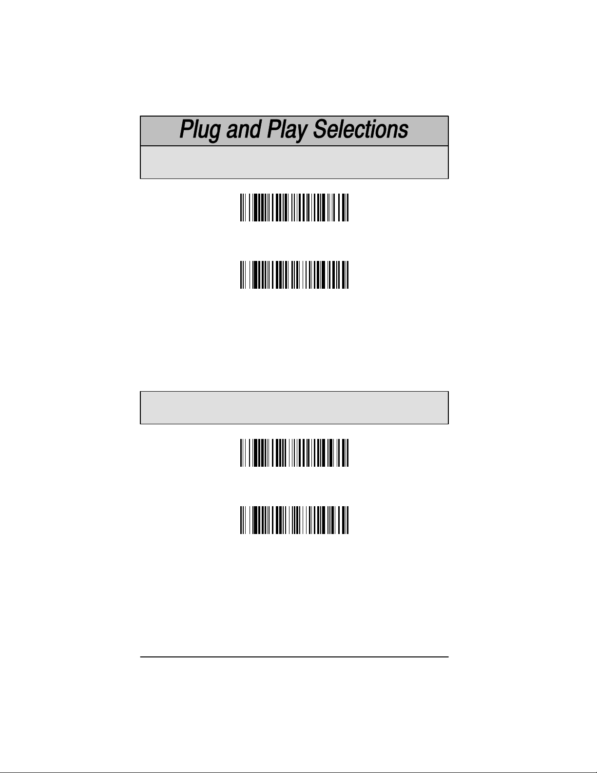
IBM 468X/9X Ports 5B, 9B, and 17 Interface
Scan one of the following “Plug and Play” codes to program the interface for
IBM 4683 Port 5B, 9B, or 17.
Note:When using any of the IBM 4683 interfaces, the maximum allowable
data rate into the base aux port is 9600 baud.
IBM 468X/9X Port 5B Interface
IBM 468X/9X Port 9B
HHBCR-1 Interface
IBM 468X/9X Port 9B
HHBCR-2 Interface
IBM 468X/9X Port 17 Interface
Cordless System Manual
2–3
Page 28
Industrial Interface, Aux Port: Wand Emulation
Black High
Wand Emulation (Code 39 Format) Interface
Wand Emulation (Same Code Format) Interface
These bar codes also program the following parameters:
Programmable Option Setting
Transmission Rate 25 inches per second
Output Polarity Black High
Industrial Interface, Aux Port: Wand Emulation
White High
Wand Emulation (Code 39 Format) Interface
Wand Emulation (Same Code Format) Interface
These bar codes also program the following parameters:
Programmable Option Setting
Transmission Rate 25 inches per second
Output Polarity White High
Supports Code 39, UPC, EAN, Code 128, Interleaved 2 of 5, and Codabar.
All other codes output as Code 39.
2–4
Cordless System Manual
Page 29
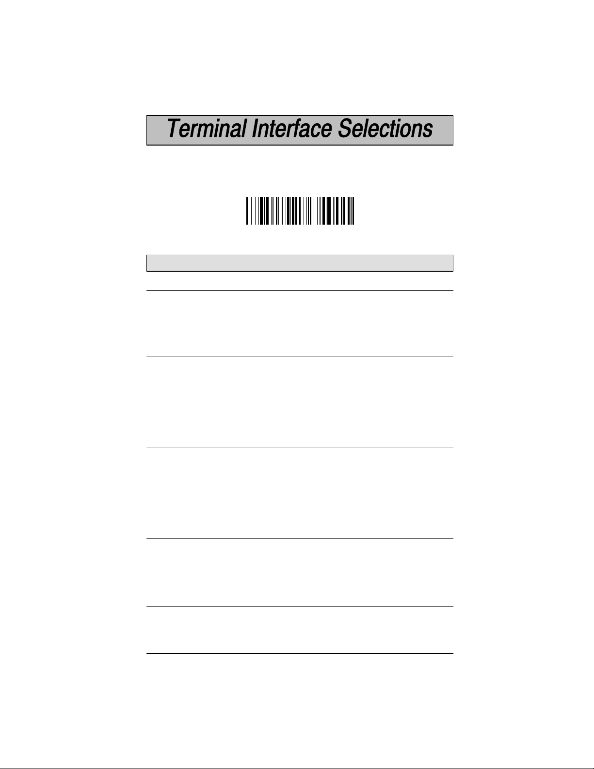
If your terminal is not one of the Plug and Play options, you must program one
of the terminals listed below. To program the terminal interface, scan the
Program T erminal Interface bar code below , then scan the appropriate Terminal
I.D. code and Save from the Programming Chart on the inside back cover of this
manual.
Program Terminal Interface
(Factory Default = ID 003)
Supported T erminals
Terminal Model(s) Terminal I.D.
Bull BDS–7 Honeywell (HDS–7) 035
DEC PC433 SE (Portable PC) 003
DEC VT–220, 320, 330, 340, 420 004
DELL Latitude (Portable PC) 003
DTK 486 SLC (Portable PC) 003
Fujitsu Stylistic (Portable PC) 003
IBM PC XT 001
IBM PS/2 25, 30, 77DX2 002
IBM AT, PS/2 30–286, 50, 55SX, 60, 70, 003
70–061, 70–121, 80
IBM AT Compatibles Keyboard Emulation 003
(Non-wedge)
IBM Thinkpad 365, 755 CV (Portable PC) 003
IBM 102 Key 3151, 3161, 3162, 3163, 3179, 3191, 006
3192, 3194, 3196, 3197, 3471, 3472,
3476, 3477, 3482, 3486, 3488
IBM 122 Key 3179–1, 3191, 3192, 3471, 3472, 3194 007
IBM 122 Key 3196, 3197, 3476, 3477, 3482, 3486, 008
3488
Lee Data IIS 007
Link ANSI MC–3+, MC–5 015
Link ASCII MC–3+, MC–5 014
Link Enhanced PC MC–3+, MC–5 018
Midwest Micro Elite TS 30 PS (Portable PC) 003
Cordless System Manual
2–5
Page 30

Supported T erminals
(Factory Default = ID 003)
Terminal Model(s) Terminal I.D.
Mitak 4022 (Portable PC) 003 [
Olivetti M19, M24, M28, M200 001
Olivetti M240, M250, M290, M380, P500 003
Relisys TR 175 003
RS-232 Host Port 050
RS-232 Aux Port 000
Serial Wedge 050
Televideo 990, 995, 9060 002
Texas Instruments Extensa 560CD (Portable PC) 003 [
Toshiba 2600 (Portable PC) 003 [
Toshiba Satelite T1960, T2130, CS (Portable PC) 003 [
Wand Emulation Code 39 output (via Aux Port) ]
Wand Emulation Same Code output (via Aux Port) ]
WYSE WY–30 013
WYSE WY–85/185 016
WYSE ANSI WY 60, 120, 150, 160, 325, 370, 99GT 015
WYSE ASCII WY 60, 120, 150, 160, 325, 370, 99GT 014
WYSE Enhanced PC WY 60, 120, 150, 160 018
Zenith Z–note (Portable PC) 003 [
[
Emulate External Keyboard and Automatic Direct Connect Mode may also
need to be turned on (see pages 2–8 and 2–9).
]
Use Plug and Play Selections on page 2–4.
2–6
Cordless System Manual
Page 31

Keyboard Country Selection
This programming selection allows you to re-map the keyboard layout for the
selected country. As a general rule, the following characters are not supported
by the Cordless System for countries other than the United States:
✱ United States
Denmark, Finland, Norway , Sweden
Germany, Austria
@ | $ # { } [ ] = / ‘ \ < > ~
Belgium
France
Switzerland
Cordless System Manual
United Kingdom
Italy
2–7
Page 32

Keyboard Style Selections
Keyboard Style Selections
This programming selection allows you to program special keyboard features,
such as Caps Lock and Shift Lock.
Regular
Caps Lock
Shift Lock
to U.S. keyboards.)
Automatic Caps Lock
software tracks and reflects if you have Caps Lock on or off (A T and PS/2 only).
This selection can only be used with systems that have an LED that notes the
Caps Lock status.
Emulate External Keyboard
keyboard (IBM A T or equivalent).
is used when you normally have the Caps Lock key off.
is used when you normally have the Caps Lock key on.
is used when you normally have the Shift Lock key on. (Not common
is used if you change the Caps Lock key on and off. The
should be scanned if you do not have an external
✱ Regular
Caps Lock
Shift Lock
Emulate External Keyboard
2–8
Automatic Caps Lock
Cordless System Manual
Page 33

Keyboard Style Modifiers
Keyboard Style Modifiers
This programming selection allows you to program special keyboard features,
such as CTRL+ codes and Turbo Mode.
Control + ASCII Mode On
sends key combinations for ASCII control characters for values 00–1F . Refer to
page 6–1 for CTRL+ Values.
Turbo Mode
Cordless System to send characters to the terminal faster.
Numeric Keypad Mode
characters as if entered from a numeric keypad.
Automatic Direct Connect
selected (above), Automatic Direct Connect Mode keeps the integrated
keyboard from becoming permanently disabled. (This selection disables the
keyboard for the duration of the bar code transmission.)
Control + ASCII Mode On
– Selecting Turbo Mode On, (for the IBM AT only), programs the
– If you scan this selection, the Cordless System
– Selecting Numeric Keypad Mode On sends numeric
– When Emulate External Keyboard has been
✱ Control + ASCII Mode Off
Turbo Mode On
Numeric Keypad Mode On
Automatic Direct Connect Mode On
Cordless System Manual
✱ Turbo Mode Off
✱ Numeric Keypad Mode Off
✱ Automatic Direct Connect Mode Off
2–9
Page 34

Output Delays Selection
This selection provides control of the time delays between data output by the
Cordless System to the host terminal. The actual delay is 5 milliseconds
multiplied by the programmed value (00 – 99).
Intercharacter Delay
Cordless System to the host terminal.
Interfunction Delay
the Cordless System to the host terminal.
Intermessage Delay
output by the Cordless System to the host terminal.
Example: Y ou need a 45 millisecond delay . Scan the
code. Scan “0,” “9,” and Save on the Programming Chart (09 x 5ms = 45ms).
Intercharacter Delay (x5mS)
Intermessage Delay (x5mS)
is the time delay between data characters output by the
is the time delay between function (key) codes output by
is the time delay between data messages or records
Default = 00.
Intercharacter Delay
Interfunction Delay (x5mS)
bar
A two-digit number and Save are required after scanning this programming
bar code. Refer to the Programming Chart (inside back cover).
2–10
Cordless System Manual
Page 35

Transmission Rate Selection
This programming selection sets the transmission rate from 10 ips (inches per
second) to 300 ips if the Cordless System is in Wand Emulation mode.
Programming the transmission rate causes the data to be sent at the specified
rate. The programmed transmission rate must be compatible with the device
receiving the bar code data.
10
✱ 25
40
80
120
150
200
300
Output Polarity Selection
This selection allows you to set the output logic convention for the digital output.
The choices are White High (“Laser” output) and Black High.
White High
✱ Black High
Cordless System Manual
2–11
Page 36

Base Low Power Mode
You may want the base unit to draw less power when it is being powered by a
portable data terminal or laptop. Use Base Low Power mode to tell the base to
draw less power.
✱ Off
On
Note:Using Base Low Power Mode slows decode time.
Battery Conservation Mode
In order to preserve scanner battery power, you can set the scanner to “go to
sleep” after the scanner or its base has been idle for a certain length of time. A
cordless scanner “checks in” with its base unit on a periodic basis. If the base
unit has been turned off, you can set the scanner to turn itself off as well (sleep
mode). If you prefer, you can set the scanner to turn itself of f regardless of the
base unit state (nap mode). Once a scanner is off, or asleep, a single trigger
pull wakes it up and begins the reassociation process, see page 1–12. A
second trigger pull is required to scan a code.
If you want the scanner to turn off after a period of inactivity, regardless of the
state of the base, scan Don’t Check for Network Base Before Timeout (nap
mode), then scan the desired timeout length code (page 2–13). When the
scanner has been idle for the timeout length, it turns itself off. If the scanner
has shown no activity for 1 hour, it will automatically shut of f by default.
2–12
Don’t Check for Network
Base Before Timeout
Cordless System Manual
Page 37

Battery Conservation Mode (continued)
If you want the scanner to turn off when the base is powered down, scan Check
for Network Before Timeout (sleep mode), then scan the desired timeout length
code (page 2–13). If the scanner gets no response from the base after the
timeout length, the scanner powers down.
Check for Network Base
Before Timeout
No Timeout indicates the scanner always remains on, which drains the battery
faster than the other settings.
✱ No Timeout
Timeout Selections
Timeout after 15 minutes
Timeout after 45 minutes
Cordless System Manual
Timeout after 30 minutes
✱ Timeout after 1 hour
2–13
Page 38

Reset Factory Settings
Scanning the
to the original factory settings, clearing any programming changes you may have
made. Y ou may reset the factory default settings for the current application group
or for all application groups.
The Current Application Group Default defaults only the settings described in
Section 4 of this manual.
The ALL Application Groups Default sets the terminal ID to 003, then changes
all settings to factory default values. (See the Defaults section in the back of this
manual for a listing of all the factory defaults.)
Factory Default Settings
Factory Default Settings: Current Application Group
Factory Default Settings: ALL Application Groups
bar code resets the Cordless System
Status Check
Scan the
Base software revision level to the host terminal. The Base software revision will
be printed out as “
“X’s” and “K’s” will vary according to the firmware revision.)
Show Base Software Revision
Base software revision: X.XX, Radio: K.KK.” (The
bar code to transmit the Cordless
Show Base Software Revision
Scan the
Scanner software revision level to the host terminal. The scanner software
revision will be printed out as “
K.KK
2–14
Show Scanner Software Revision
Scanner software revision: Y.YY, Radio:
.” (The “Y’s” and “K’s” will vary according to the firmware revision.)
Show Scanner Software Revision
Cordless System Manual
bar code to transmit the Cordless
Page 39

Section 3 Communications Menu
Introduction
Use this section to program the communications parameters for the Cordless
System.
This programming section contains the following menu selections:
• Host Port Communications (RS-232)
• Auxiliary Port Communications (RS-232)
Cordless System Manual
3–1
Page 40

✱ Default All Host Port Communications ✱
Baud Rate Selection
This selection sets the baud rate from 300 bits per second to 38,400 bits per
second. Programming baud rate causes the data to be sent at the specified rate.
The host terminal must be set up for the same baud rate as the Cordless System
to ensure reliable communication.
300
600
1200
2400
3–2
4800
9600
19200
✱ 38400
Cordless System Manual
Page 41

Parity Selection
This selection provides a means of checking character bit patterns for validity.
The Cordless System can be configured to operate under Even, Odd,
Mark, None, or Space parity options. The host terminal must be set up for the
same parity as the Cordless System to ensure reliable communication.
✱ None
Space
Mark
Even
Odd
Word Length Data Bits Selection
This selection sets the Word Length at
If an application requires only ASCII Hex characters 0 through 7F decimal (text,
digits, and punctuation), select 7 data bits. For applications requiring use of the
full ASCII set, select 8 data bits per character.
7 Data Bits
Cordless System Manual
seven or eight bits of data
✱ 8 Data Bits
per character.
3–3
Page 42

Word Length Stop Bits Selection
This selection sets the Word Length at
one or two stop bits
.
✱ 1 Stop Bit
2 Stop Bits
Serial Wedge Output Selection
This selection selects the serial output direction required by your application. P1
and P2 are serial wedge designations printed on the serial wedge cable. Usually ,
one goes to the host and one goes to the terminal, depending on your specific
application and the serial wedge cable.
To P1
To P1 and P2
To P2
✱ None (Host Port RS-232)
Hardware Flow Control Selection
This selection turns on hardware flow control that checks for a CTS signal before
sending data. This option is useful when your application supports the CTS
signal.
Selection.
3–4
Note: This selection cannot be used with Serial Wedge Output
On
✱ Off
Cordless System Manual
Page 43

Host ACK Selection
This selection programs the Cordless System to wait for a confirmation signal
(ACK) from the host after bar code data has been sent. When Host ACK is turned
on, the host system must be programmed to generate Escape Commands (see
section below) for user feedback. Page 1–13 in the Getting Started Section
explains how Host ACK works and provides an illustration of the feature.
Host ACK mode is designed to respond to a specific Application Work Group
(see Section 4 for more information on Work Groups); the host system issues an
Escape sequence to
commands may be strung together to create custom beep/blink sequences.
An example of an Escape string to create a “low, medium, high” beep sequence
for scanners in Application Work Group 2 would be: “
character indicates the Work Group and the comma is used as the delimiter . If
it can’t be determined that the data has been properly sent to the host system,
the scanner issues 4 beeps (low, high, low, high tones). You must then check
to see if the scanned data was received by the host system.
Note: Host ACK mode will only work with a host system that supports RTS/CTS
flow control. If your host system does not support RTS/CTS handshaking,
turning on Host ACK selection will cause some or all of your data to be lost.
On
all
scanners in the Work Group. Up to twenty Escape
2esc4esc5esc6,
”. The first
Escape Commands
The Cordless System will respond to beep and blink commands from the host
system. The format for these commands is:
y Esc x ,
of the Escape commands listed below. A comma must be used to terminate the
command. The table below lists the Escape commands that must be generated
from the host system and the resulting action(s).
Command Action
Esc a
Esc b
Esc 1
Esc 2
Esc 3
Esc 4
Esc 5
Esc 6
Esc 7
Esc 8
where “y” is the Application Work Group number and “x” is one
Beep (two high tones), illuminate green LED for two seconds
Beep (three low tones), illuminate green LED nine times
Illuminate green LED for 135 milliseconds
Illuminate green LED for two seconds
Illuminate green LED for five seconds
One beep at low volume
One beep at medium volume
One beep at high volume
Beep (one medium tone), illuminate green LED two seconds
Beep (three low tones), illuminate green LED nine times
✱ Off
Note: Host ACK may be used with Decode Beep Selection (see page 4–4).
Cordless System Manual
3–5
Page 44

✱ Default All Auxiliary Port Communications ✱
Baud Rate Selection
This selection sets the baud rate from 300 bits per second to 38,400 bits per
second. Programming baud rate causes the data to be sent at the specified rate.
The device connected to the Auxiliary Port must be set up for the same baud rate
as the Aux Port to ensure reliable communication.
300
600
1200
2400
3–6
4800
9600
19200
✱ 38400
Cordless System Manual
Page 45

Parity Selection
This selection provides a means of checking character bit patterns for validity.
The Auxiliary Port can be configured to operate under Even, Odd, Mark, None,
or Space parity options. The device connected to the Auxiliary Port must be set
up for the same parity as the Aux Port to ensure reliable communication.
✱ None
Space
Mark
Even
Odd
Word Length Data Bits Selection
This selection sets the Word Length at
If an application requires only ASCII Hex characters 0 through 7F decimal (text,
digits, and punctuation), select 7 data bits. For applications requiring use of the
full ASCII set, select 8 data bits per character.
7 Data Bits
seven or eight bits of data
per character.
✱ 8 Data Bits
Cordless System Manual
3–7
Page 46

Word Length Stop Bits Selection
This selection sets the Word Length at
one or two stop bits
.
✱ 1 Stop Bit
2 Stop Bits
Protocol Selection
This selection programs the Auxiliary Port for the protocol required by the input
device to the Auxiliary Port. The protocol is a set of rules concerning the
exchange of data between serially communicating devices. The Auxiliary Port
supports Record, Burst, and Ack / Nak protocols when receiving data from an
RS-232 device.
✱ Record
Burst
Record Ack / Nak
Block Ack / Nak
Aux Port I.D. Transmit Selection
This will attach the Aux Port identifier (which is the letter “r”) to the incoming data
at the Auxiliary Port and will send it along with the data to the host device.
On
✱ Off
3–8
Cordless System Manual
Page 47

IBM 4683 Async Address Selections
If you are going to program the interface for IBM 4683 Async Addresses, you
must first program the Terminal ID as 51 (see page 2–5). Then, scan one of
the programming codes below for your 4683 Async Address selection.
Note:When using any of the IBM 4683 interfaces, the maximum allowable
data rate into the base aux port is 9600 baud.
Address $68
(Socket 23: 2A Left)
Address $69
(Socket 23: 2B Right)
Address $64
(Socket 25: 2A Left)
Address $65
(Socket 25: 2B Right)
Aux Port Disable
Cordless System Manual
3–9
Page 48

Hardware Flow Control Selection
This selection turns on hardware flow control that checks for a CTS signal before
sending data. This option is useful when your application supports the CTS
signal.
On
✱ Off
Note: The Auxiliary Port receive function will only work properly if RTS/CTS or
ACK/NAK flow control is used. If your host system does not support RTS/CTS
or ACK/NAK handshaking, some or all of your data will be lost.
Data Character Selection
This selection selects the serial output data characters that may be sent from the
RS-232 device connected to the Auxiliary Port.
Default SOR Character = none (NUL: 00).
Default EOR Character = Carriage Return (CR: 0D).
Default SOB Character = none (NUL: 00).
Default EOB Character = End of Text (EOT: 04).
SOR (Start of Record)
EOR (End of Record)
SOB (Start of Block)
EOB (End of Block)
A two-digit number and Save are required after scanning this programming
bar code. Refer to the Programming Chart (inside back cover).
3–10
Cordless System Manual
Page 49

Aux Prefix and Suffix
Aux Prefix and Suffix characters are data characters you may assign to incoming
Auxiliary Port data.
Data frame –>
Characters for the Prefix and Suffix are selected by their hexadecimal ASCII
value, up to 12 characters each. Prefix and Suffix characters may be assigned
to all incoming data.
Default Prefix (incoming data) = none.
Default Suffix (incoming data) = none.
Default Prefix (outgoing data) = none.
Default Suffix (outgoing data) = Carriage Return (CR).
Programming Steps to Add an Aux Prefix / Suffix to Incoming Data:
➊ To add a Prefix, scan the
To add a Suffix, scan the
➋ Scan two bar codes for the Hex Value “72” (“r,” which represents the
identifier for the Aux Port). Scan the two digits on the Programming
Chart (on the inside back cover of this manual).
➌ Refer to the Hex ASCII Chart (page 3–12) to find the Hex value that
represents the ASCII characters you wish to attach to the data. Use the
Programming Chart (inside back cover) to scan the alphanumeric
combination that represents the ASCII characters.
➍ To complete Aux Prefix / Suffix programming, scan either:
Prefix SuffixMessage
Add Aux Prefix
Add Aux Suffix
Save
– This exits, saving the Prefix / Suffix selections you just
assigned.
Discard –
This exits without changing the Prefix / Suffix.
programming bar code.
programming bar code.
Other Programming Selections: Scanning the
bar code sets the default Prefix or Suffix (shown above).
Suffix
Scanning the
or Suffix selections.
If you want to turn off the prefix or suffix formatting for a period of time, scan
Disable Aux Prefix/Suffix
Clear All Prefixes
. To turn back on, scan
or
Clear All Suffixes
Default Prefix
bar code deletes all Prefix
or
Default
Enable Aux Prefix/Suffix
Note: Aux Prefix / Suffix programming examples may be found on page 3–12.
Cordless System Manual
3–11
.
Page 50

Aux Prefix and Suffix Examples
Example 1: Add a Prefix
To add an HT (tab) Prefix to incoming data:
Scan the
Scan 7 and 2 on the Programming Chart (inside back cover).
An “HT” is equivalent to “09” (see the Hex ASCII Chart). Scan 0 and 9
on the Programming Chart.
Scan
Example 2: Add a Suffix
To add a CR (carriage return) Suffix to incoming data:
Scan the
Scan 7 and 2 on the Programming Chart (inside back cover).
A “CR” is equivalent to “0D” (see the Hex ASCII Chart). Scan 0 and D
on the Programming Chart.
Scan
Add Aux Prefix
Save
.
Add Aux Suffix
Save
.
Prefix Selection bar code.
Suffix Selection bar code.
Hex to ASCII Conversion Chart
ASCII Hex ASCII Hex ASCII HexASCII Hex ASCII Hex ASCII Hex ASCII Hex ASCII Hex
p
60
‘
50
P
40
@
30
0
20
SP
10
DLE
00
NUL
SOH
STX
ETX
EOT
ENQ
ACK
BEL
BS
HT
LF
VT
FF
CR
SO
SI
01
02
03
04
05
06
07
08
09
0A
0B
0C
0D
0E
0F
DC1
DC2
DC3
DC4
NAK
SYN
ETB
CAN
EM
SUB
ESC
FS
GS
RS
US
11
12
13
14
15
16
17
18
19
1A
1B
1C
1D
1E
1F
!
”
#
$
%
&
’
(
)
*
+
,
–
.
/
21
22
23
24
25
26
27
28
29
2A
2B
2C
2D
2E
2F
1
2
3
4
5
6
7
8
9
:
;
<
=
>
?
32
33
34
35
36
37
38
39
3A
3B
3C
3D
3E
3F
B
C
D
E
F
G
H
I
J
K
L
M
N
O
42
43
44
45
46
47
48
49
4A
4B
4C
4D
4E
4F
R
S
T
U
V
W
X
Y
Z
[
\
]
^
_
52
53
54
55
56
57
58
59
5A
5B
5C
5D
5E
5F
b
c
d
e
f
g
h
i
j
k
l
m
n
o
a
51
Q
41
A
31
61
62
63
64
65
66
67
68
69
6A
6B
6C
6D
6E
6F
q
r
s
t
u
v
w
x
y
z
{
|
}
~
DEL
70
71
72
73
74
75
76
77
78
79
7A
7B
7C
7D
7E
7F
3–12
Cordless System Manual
Page 51

Add Aux Prefix
Aux Prefix Selection
Clear All Aux Prefixes
Add Aux Suffix
Clear All Aux Suffixes
Exit Selection for Aux Prefix / Suffix
Save
Default Aux Prefix
Aux Suffix Selection
Default Aux Suffix
(none)
(CR)
Discard
One or more two-digit numbers and Save are required after scanning this
programming bar code. Refer to the Programming Chart (inside back cover).
Cordless System Manual
3–13
Page 52

Aux Prefix Enable/Disable
The following selections allow you to Enable and Disable Aux Prefix and
Suffix formatting. These codes are used when you want to toggle between
turning on and off the prefix and/or suffix formatting.
Enable Aux Prefix
Disable Aux Prefix
Aux Suffix Enable/Disable
Enable Aux Suffix
Disable Aux Suffix
3–14
Cordless System Manual
Page 53

Aux Data Format Editor
The Aux Data Format Editor selections are used to edit incoming data to the
aux port. For example, you can use the Aux Data Format Editor to insert
characters at certain points in bar code data as it is scanned.
It is not necessary to use the Aux Data Format Editor. A set of defaults for the
aux data format is already programmed in the base. The selections in the
following pages are used only if you wish to alter the default settings.
Aux Data Format setting = none.
If you have changed aux data format settings, and wish to clear all formats and
return to the defaults, scan the Default Aux Data Format code.
To Add an Aux Data Format
STEP 1. Scan the Enter Aux Data Format symbol (pg. 3–19).
STEP 2. Primary/Alternate Format
STEP 3. Terminal Type
STEP 4. Code I.D.
STEP 5. Length
STEP 6. Editor Commands
STEP 7. Scan Save to save your entries.
Determine if this will be your primary aux data format, or one of 3
alternate formats. (Alternate formats allow you “single shot”
capability to scan one bar code using a different aux data format.
After the one bar code has been read, the scanner reverts to the
primary aux data format. See page 3–21.) If you are programming
the primary format, scan 0. If you are programming an alternate
format, scan 1, 2, or 3, depending on the alternate format you are
programming.
Refer to the Supported Terminals Chart (page 2–5) and locate the
Terminal ID number for your PC. Scan three numeric bar codes on
the inside back cover to program the scanner for your terminal ID
(you must enter 3 digits). For example, scan 0 0 3 for an IBM AT.
Scan 7 then 2 from the Programming Chart. (This is the hex
value for “r,” the aux port I.D.)
Specify what length (up to 9999 characters) of data will be
acceptable for this symbology . Scan the four digit data length from
the Programming Chart. (Note: 50 characters is entered as 0050.
9999 is a universal number, indicating all lengths.)
Refer to the Format Editor Commands (page 3–17). Scan the
symbols that represent the command you want to enter. 94
alphanumeric characters may be entered for each symbology data
format.
Default
Cordless System Manual
3–15
Page 54

Other Programming Selections
Clear One Aux Data Format
This deletes one aux data format for one symbology . If you are clearing
the primary aux format, scan 0. If you are clearing an alternate format,
scan 1, 2, or 3, depending on the alternate format you are clearing.
Scan the Terminal Type (refer to the Supported Terminals Chart on page
2–5), then 7, 2 (for the aux port I.D.), and the length of the format you
want to delete. That length aux data format for that symbology is
deleted and all other formats are unaffected.
Save
This exits, saving any Aux Data Format changes.
Discard
This exits without saving any Aux Data Format changes.
Aux Data Formatter Example
Five digit data is sent to the Auxiliary Port, however the host system can only
accept eight digit data. Three zeroes must be added to the beginning of the
Aux Port data.
Received
12345 00012345
Refer to the Aux Format Editor Commands on page 3–17 to format the
following example. The programming bar codes on page 3–19 and the
alphanumeric bar codes on the inside back cover are used to program the aux
data formatter.
Scan the Enter Aux Data Format bar code (page 3–19).
Scan 0 9 9 (all terminal types).
Scan 7 2 (the hex value for the aux port).
Scan 0 0 0 5 (the data length).
The Aux Data Editor Commands are:
Scan F 4 (see page 3–17 for a description).
Scan 3 0 (hex value for 0).
Scan 0 3 (indicating the 0 should be sent 3 times).
Scan F 1 to send the data, then 0 0 (the hex value for NUL).
Scan Save to end the Aux Data Formatting.
Must send
3–16
Cordless System Manual
Page 55

Aux Format Editor Commands
Send Commands
F1 Send all characters followed by “xx” key or function code, starting from current
cursor position.
see Hex to ASCII Conversion chart, page 3–12.)
F2 Send “nn” characters followed by “xx” key or function code, starting from
current cursor position.
(00-99) for the number of characters and xx stands for the hex value for an
ASCII code. See Hex to ASCII Conversion chart, page 3–12.)
F3 Send up to but not including “ss” character (Search and Send) starting from
current cursor position, leaving cursor pointing to “ss” character followed by
“xx” key or function code.
values for ASCII codes, see Hex to ASCII Conversion chart, page 3–12.)
F4 Send “xx” character “nn” times (Insert) leaving cursor in current cursor
position.
see Hex to ASCII Conversion chart, page 3–12, and nn is the numeric value
(00-99) for the number of times it should be sent.)
E9 Send all but the last “nn” characters, starting from the current cursor position.
Syntax = E9nn
that will not be sent at the end of the message.)
Syntax = F1xx
Syntax = F4xxnn
(nn is the numeric value (00-99) for the number of characters
(xx stands for the hex value for an ASCII code,
Syntax = F2nnxx
Syntax = F3ssxx
(xx stands for the hex value for an ASCII code,
(nn stands for the numeric value
(ss and xx both stand for the hex
Move Commands
F5 Move the cursor ahead “nn” characters from current cursor position.
Syntax = F5nn
characters the cursor should be moved ahead.)
F6 Move the cursor back “nn” characters from current cursor position.
Syntax = F6nn
characters the cursor should be moved back.)
F7 Move the cursor to the beginning of the data string.
EA Move the cursor to the end of the data string.
(nn stands for the numeric value (00-99) for the number of
(nn stands for the numeric value (00-99) for the number of
Syntax = F7.
Syntax = EA
Search Commands
F8 Search ahead for “xx” character from current cursor position, leaving cursor
pointing to “xx” character .
ASCII code, see Hex to ASCII Conversion chart, page 3–12.)
F9 Search back for “xx” character from current cursor position, leaving cursor
pointing to “xx” character .
ASCII code, see Hex to ASCII Conversion chart, page 3–12.)
E6 Search ahead for the last instance of “xx” character from the current cursor
position, then increment cursor.
for an ASCII code, see Hex to ASCII Conversion chart, page 3–12.)
E7 Search back for the last instance of “xx” character from the current cursor
position, then increment cursor.
for an ASCII code, see Hex to ASCII Conversion chart, page 3–12.)
Syntax = F8xx
Syntax = F9xx
Syntax = E6xx
Syntax = E7xx
(xx stands for the hex value for an
(xx stands for the hex value for an
(xx stands for the hex value
(xx stands for the hex value
Cordless System Manual
3–17
Page 56

Miscellaneous Commands
FB Suppress all occurrences of up to 15 different characters, starting at the
current cursor position, as the cursor is advanced by other commands. When
the FC command is encountered, the suppress function is terminated. The
cursor is not moved by the FB command. Syntax = FBnnxxyy . .zz where
nn is a count of the number suppress characters in the list and xxyy .. zz is
the list of characters to be suppressed. (xx stands for the hex value for an
ASCII code, see Hex to ASCII Conversion chart, page 3–12.)
FC Disable suppress filter and clear all suppressed characters.
EB Toggles the auxiliary port on and off. This command is used when data is
normally transmitted out the main port, and needs to be temporarily sent out
the aux port. The first EB in a format string opens the aux port, temporarily
re-directing data transmission out the aux port. Send commands (F1, F2, F3,
F4) are then used to transmit data. A second EB command closes the aux
port and resumes normal data transmission through the main port.
= EB
.
E4 Replaces up to 15 characters in the data string with user specified characters.
Replacement continues until the E5 command is encountered.
E4nnxx
be replaced plus replacement characters; xx
1xx2yy1yy2
replaced and xx
zz
.
2
...zz1zz
defines replacement characters, continuing through zz1 and
2
E5 Terminates character replacement.
where nn is the total count of both characters to
2
defines characters to be
1
Syntax = E5.
FE Compare character in current cursor position to the character “xx.” If
characters are equal, increment cursor. If characters are not equal, no format
match.
Syntax = FExx
(xx stands for the hex value for an ASCII code, see
Hex to ASCII Conversion chart, page 3–12.)
EC Check to make sure there is a numeric character at the current cursor position.
If character is not numeric, format is aborted.
Syntax = EC
ED Check to make sure there is a non-numeric character at the current cursor
position. If character is numeric, format is aborted.
Syntax = ED
EF Inserts a delay of up to 49,995 milliseconds (in multiples of 5).
where nn is a count of the number 5 ms delays, up to 9,999.
Syntax = FC.
Syntax
Syntax =
.
.
Syntax = EFnn
3–18
Cordless System Manual
Page 57

Aux Data Format Editor
C
See pages 3–15 through 3–18 for a description of Aux Data Format selections
and commands.
Enter Aux Data Format
Default Aux Data Format
lear One Aux Data Format
Clear All Aux Data Formats
Save
Discard
Cordless System Manual
3–19
Page 58

Aux Data Formatter
When Aux Data Formatter is turned off, the data coming in to the aux port is
output to the host as received (including prefixes and suffixes).
✱ Aux Data Formatter On
Aux Data Formatter Off
Require Aux Data Format
When Aux Data Formatter is required, all incoming data must conform to an
edited format or the base does not transmit the input data to the host device. If
this occurs, the data is discarded.
Aux Data Format Required
Default = Not Required.
✱ Aux Data Format
Not Required
3–20
Cordless System Manual
Page 59

Alternate Aux Data Formats
Alternate formats allow you “single shot” capability to edit incoming data using a
different aux data format than your primary aux format. When aux data formats
are programmed (see page 3–15), you must input whether you are
programming the primary aux format, or an alternate format numbered 1, 2, or
3.
An alternate aux format is initiated by scanning one of the 3 alternate aux
format bar codes below. The base will edit the incoming data, formatting the
data with the selected alternate aux format, then revert immediately to the
primary aux format.
Alternate Aux Data Format 1
Alternate Aux Data Format 2
Alternate Aux Data Format 3
Cordless System Manual
3–21
Page 60

3–22
Cordless System Manual
Page 61

Section 4 Application Work Groups Menu
Introduction
Use this section to program parameters for application work groups for the
Cordless System.
This programming section contains the following menu selections:
• Output Selections (User Feedback)
• Prefix and Suffix
• Data Formatter
When you set up and connect the Cordless System to your host system, you
associate the Cordless Scanner to its Base unit. If you are using more than one
Cordless Scanner, you may also set up application work groups. (Instructions
for associating more scanners – up to nine – to the Base are on page 1–7.)
Application work groups may be set up in different configurations using the
programming selections found in this section of the manual. For example, one
group may need the beeper turned off, will only scan Code 39 bar codes, and
needs a carriage return suffix added to the data being sent to the host system
via the Base. Another group may require that scanner voting be turned on, will
scan UPC A, and needs a space added to the transmitted data, between the main
UPC bar code data and the five digit addenda.
The Application Work Groups Selection (on the next page) sets up the
application work group(s). After you’ve scanned the association bar code on the
Base, scan one of the work group numbers to assign the Cordless Scanner to
a specific group. Y ou may then program whatever parameters your application
requires from the Output (User Feedback), Prefix and Suffix, and Data Formatter
Selections menu pages.
T o add a new Cordless Scanner to an established group, associate the scanner
to the Base and scan the application work group number. The scanner will
operate and send data to the host system according to that group’s programmed
selections. Any programming selections you change or make with one Cordless
Scanner will affect all the scanners in a work group.
Note: T o program a group’ s parameters, you must first scan the group number
and then the programming selections (prefix, suffix, data formatter, etc.). The
parameters can’t be programmed first and then “made” a group by scanning an
application work group number.
To remove a scanner associated with a Base unit, use the Remove Scanner
Selection on page 4–3. For instance, if nine scanners are associated with a
Base (the maximum number) and you want to add a new scanner, you will need
to remove one scanner from the established work groups. After removing one
scanner by using the Remove Scanner programming bar code, add the new
scanner by scanning the association bar code on the Base unit.
Cordless System Manual
4–1
Page 62

Application Work Group Selection
This programming selection sets up application work groups sharing specific
programming settings (such as Beeper Volume, Scanner V oting, Prefix/ Suffix,
and Data Formatter). Scan the group number and then program the selections
your application requires. (Refer to the introduction, page 4–1, for more
information on application work groups.)
✱ Group 0
Group 1
Group 2
Group 3
4–2
Group 4
Group 5
Group 6
Group 7
Group 8
Cordless System Manual
Page 63

Remove Scanner Selection
This programming selection removes a scanner from an associated Base unit.
Remove Scanner
Beeper Volume Selection
Off
Low
Medium
✱ High
Cordless System Manual
4–3
Page 64

Beeper Pitch
You may wish to set your beeper to a higher or lower pitch. This feature is
helpful if there are several scanners being used in close proximity . Different
pitches make it easier to distinguish which scanner is beeping.
Low
✱ Medium
Medium High
High
Decode Beep Selection
Note: Decode Beep mode is active only when the programming selections
Host ACK (page 3–5) or Data Format Required (page 4–16) are turned on.
When Host Ack Selection is on, the scanner will only beep/blink in response to
the Escape commands generated by the host. Should you also want the
scanner to beep when a bar code has been successfully decoded, turn on the
Decode Beep Selection.
When Data Format Required is on, the scanner will only beep if the input data
conforms to the edited format or triple beep if it does not meet the format
requirements. Should you also want the scanner to beep when a bar code has
been successfully read and sent to the host from the base, turn on the Decode
Beep Selection.
4–4
On
✱ Off
Cordless System Manual
Page 65

Scanner Voting Selection
When Scanner Voting is turned on, the Cordless System requires three (3)
identical, consecutive scans before the bar code data will be accepted and
transmitted to the terminal. When this selection is turned off, the bar code data
will be transmitted following one (1) valid scan.
On
✱ Off
Laser Marker Beam
When this selection is turned on (short or long duration), the Cordless Scanner
shows a marker or locator beam before the red scan line opens across a bar code
and the scanning process begins. The marker beam, emitted by centering the
optical scan mirror, appears as a bright spot of illumination that serves as an
aiming guide when bar code targets are at a distance from the scanner.
Note: If this selection is turned on in the 5770 Standard or 5770 HD products,
the scan rate is diminished.
✱ Off
Long Duration (1.2 seconds)
Cordless System Manual
Short Duration (.5 seconds)
4–5
Page 66

AIM I.D. Prefix
This selection allows you to turn on or off the transmission of an AIM I.D. before
the decoded symbology. (See the Symbology Chart below for the single AIM
character code that identifies each symbology.) When you scan the On code,
all current prefixes are cleared, then an AIM I.D. for all symbologies is
programmed.
On
✱ Off
Code I.D. Prefix
This selection allows you to turn on or off the transmission of a Code I.D. before
the decoded symbology. (See the Symbology Chart below for the single
character code that identifies each symbology.) When you scan the On code,
all current prefixes are cleared, then a Code I.D. for all symbologies is
programmed.
On
Symbology Chart
Symbology Symbology
Codabar ]F0 a
Code 39 ]A0 b
UPC ]E0 c
EAN ]E0 d
Interleaved 2 of 5 ]I0 e
AIM
ID
4–6
Code
ID
Code 2 of 5 ]S0 f
Code 1 1 ]H0 h
Code 93 ]G0 i
Code 128 ]C0 j
Matrix 2 of 5 ]X0 m
Telepen ]B0 t
Cordless System Manual
✱ Off
AIM
ID
Code
ID
Page 67

Prefix/Suffix Description and Examples
When a bar code is scanned, additional information is sent to the host
computer along with the bar code data. This group of bar code data and
additional, user-defined data is called a “message string.” The selections in this
section are used to build the user-defined data into the message string.
Prefix and Suffix characters are data characters that can be sent before and
after scanned data. You can specify if they should be sent with all
symbologies, or only with specific symbologies. The following illustration
shows the breakdown of a message string:
Prefix Scanned Data Suffix
1-12
alpha
numeric
characters
variable
length
1-12
alpha
numeric
characters
Points to Keep In Mind
It is not necessary to build a message string. The selections in this
chapter are only used if you wish to alter the default settings.
prefix = None. Default suffix = Carriage Return
A prefix or suffix may be added or cleared from one symbology or all
symbologies.
You can add any prefix or suffix from the ASCII chart (pg. 4–11), plus
Code I.D. and Aim I.D.
You can string together several entries for several symbologies at one
time.
Enter prefixes and suffixes in the order in which you want them to
appear on the output.
.
Default
Cordless System Manual
4–7
Page 68

To Add a Prefix or Suffix:
STEP 1. Scan the Add Prefix (pg. 4–10) or Add Suffix symbol (pg. 4–10).
STEP 2. Determine the 2 digit Hex value from the Symbology Chart (pg.
STEP 3. Scan the 2 hex digits from the Programming Chart inside the back
STEP 4. Determine the hex value from the Hex to ASCII Conversion Chart
STEP 5. Scan the 2 digit hex value from the Programming Chart inside the
Note:
4–11) for the symbology to which you want to apply the prefix or
suffix.
cover or scan 9, 9 for all symbologies.
(pg. 4–11) for the prefix or suffix you wish to enter.
back cover.
Repeat Steps 4 and 5 for every prefix or suffix character.
STEP 6. Scan Save to exit and save, or scan Discard to exit without
Repeat Steps 1–6 to add a prefix or suffix for another symbology.
saving.
To Clear One or All Prefixes or Suffixes:
You can clear a single prefix or suffix, or clear all prefixes/suffixes for a
symbology. When you Clear One Prefix (Suffix), the specific character you
select is deleted from the symbology you want. When you Clear All Prefixes
(Suffixes), all the prefixes or suffixes for a symbology are deleted.
STEP 1. Scan the Clear One Prefix or Clear One Suffix symbol.
STEP 2. Determine the 2 digit Hex value from the Symbology Chart (pg.
STEP 3. Scan the 2 digit hex value from the Programming Chart inside the
STEP 4. Scan Save to exit and save, or scan Discard to exit without
4–11) for the symbology from which you want to clear the prefix or
suffix.
back cover or scan 9, 9 for all symbologies.
saving.
4–8
Cordless System Manual
Page 69

Prefix and Suffix Examples
Example 1: Add Suffix for Specific Symbology
To send a CR (carriage return) Suffix for UPC only.
Scan
The Symbology Chart indicates that the Hex value of UPC is “63.” Scan
A “CR” is equivalent to “0D” (see the Hex ASCII Chart). Scan 0 and D
Scan
Example 2: Add Suffix for
Add Suffix
6 and 3 on the Programming Chart (inside back cover).
on the Programming Chart.
Save
.
.
ALL
Symbologies
To send a CR (carriage return) Suffix for all symbologies.
Scan
The Symbology Chart indicates that the Hex value for All Symbologies
A “CR” is equivalent to “0D”. Scan 0 and D on the Programming Chart.
Scan
Example 3: Add Prefix for Specific Symbology / Suffix for
Symbologies
Add Suffix
is “99”. Scan 9 and 9 on the Programming Chart.
Save
.
.
ALL
To send an HT (tab) Prefix for UPC only and a CR / LF (carriage return / line
feed) Suffix for all symbologies.
Scan
The Symbology Chart indicates that the Hex value of UPC is “63”. Scan
An “HT” is equivalent to “09”. Scan 0 and 9 on the Programming Chart.
Scan
The Symbology Chart indicates that the Hex value for All Symbologies
A “CR” is equivalent to “0D” and an “LF” is “0A”. Scan 0, D, 0, and A
Scan
Example 4: T o Clear a Specific Prefix Entry
The Cordless System is programmed to send a CR / LF (carriage return / line
feed) Prefix for all symbologies (Hex value, 99). This is one Prefix entry .
You’ve also programmed a “#” Prefix for UPC (Hex, 63). To clear the UPC
entry , but not the Prefix entry for all symbologies.
Scan the
The Symbology Chart indicates that the Hex value for UPC is “63”.
Scan the
Add Prefix
6 and 3 on the Programming Chart.
Add Suffix
is “99”. Scan 9 and 9 on the Programming Chart.
on the Programming Chart.
Save
Clear Specific Prefix
Scan 6 and 3 on the Programming Chart.
Save Current Changes
.
.
.
Prefix Selection bar code.
Exit Selection bar code.
Cordless System Manual
4–9
Page 70

Add Prefix
Prefix Selection
Clear One Prefix
Add Suffix
Clear One Suffix
Suffix Selection
Default Prefix
Clear All Prefixes
Default Suffix
Clear All Suffixes
(none)
(CR)
Exit Selection for Prefix / Suffix
Save
Discard
One or more two-digit numbers and Save are required after scanning this
programming bar code. Refer to the Programming Chart (inside back cover).
4–10
Cordless System Manual
Page 71

Symbology Chart
ID
Hex
Value
Symbology
Code 1 1 ]H0 h 68
Code 93 ]G0 i 69
Code 128 ]C0 j 6A
Matrix 2 of 5 ]X0 m 6D
Telepen ]B0 t 74
AIM
ID
All Symbologies 99
(Prefix/Suffix Programming only.)
Code
Symbology
Codabar ]F0 a 61
Code 39 ]A0 b 62
UPC ]E0 c 63
EAN ]E0 d 64
Interleaved 2 of 5 ]I0 e 65
Code 2 of 5 ]S0 f 66
AIM
ID
Hex to ASCII Conversion Chart
ASCII Hex ASCII Hex ASCII HexASCII Hex ASCII Hex ASCII Hex ASCII Hex ASCII Hex
‘
50
P
40
@
30
0
20
SP
10
DLE
00
NUL
SOH
STX
ETX
EOT
ENQ
ACK
BEL
BS
HT
LF
VT
FF
CR
SO
SI
01
02
03
04
05
06
07
08
09
0A
0B
0C
0D
0E
0F
DC1
DC2
DC3
DC4
NAK
SYN
ETB
CAN
EM
SUB
ESC
FS
GS
RS
US
11
12
13
14
15
16
17
18
19
1A
1B
1C
1D
1E
1F
!
”
#
$
%
&
’
(
)
*
+
,
–
.
/
21
22
23
24
25
26
27
28
29
2A
2B
2C
2D
2E
2F
1
2
3
4
5
6
7
8
9
:
;
<
=
>
?
32
33
34
35
36
37
38
39
3A
3B
3C
3D
3E
3F
B
C
D
E
F
G
H
I
J
K
L
M
N
O
42
43
44
45
46
47
48
49
4A
4B
4C
4D
4E
4F
R
S
T
U
V
W
X
Y
Z
[
\
]
^
_
Q
41
A
31
51
52
53
54
55
56
57
58
59
5A
5B
5C
5D
5E
5F
a
b
c
d
e
f
g
h
i
j
k
l
m
n
o
Code
ID
60
61
62
63
64
65
66
67
68
69
6A
6B
6C
6D
6E
6F
p
q
r
s
t
u
v
w
x
y
z
{
|
}
~
DEL
Hex
Value
70
71
72
73
74
75
76
77
78
79
7A
7B
7C
7D
7E
7F
Note: Prefix / Suffix entries for specific symbologies override the universal (All
Symbologies, 99) entry.
Cordless System Manual
4–11
Page 72

Data Format Editor
The Data Format Editor selections are used to edit scanned data. For
example, you can use the Data Format Editor to insert characters at certain
points in bar code data as it is scanned.
It is not necessary to use the Data Format Editor. A set of defaults for the data
format is already programmed in the scanner. The selections in the following
pages are used only if you wish to alter the default settings.
Format setting = none.
If you have changed data format settings, and wish to clear all formats and
return to the defaults, scan the Default Data Format code.
To Add a Data Format
STEP 1. Scan the Enter Data Format symbol (pg. 4–15).
STEP 2. Primary/Alternate Format
STEP 3. Terminal Type
STEP 4. Code I.D.
STEP 5. Length
STEP 6. Editor Commands
STEP 7. Scan Save to save your entries.
Determine if this will be your primary data format, or one of 3
alternate formats. (Alternate formats allow you “single shot”
capability to scan one bar code using a different data format. After
the one bar code has been read, the scanner reverts to the primary
data format. See page 4–17.) If you are programming the primary
format, scan 0. If you are programming an alternate format, scan
1, 2, or 3, depending on the alternate format you are programming.
Refer to the Supported Terminals Chart (page 2–5) and locate the
Terminal ID number for your PC. Scan three numeric bar codes on
the inside back cover to program the scanner for your terminal ID
(you must enter 3 digits). For example, scan 0 0 3 for an AT
wedge.
On pg. 4–1 1, find the symbology to which you want to apply the
data format. Locate the Hex value for that symbology and scan the
2 digit hex value from the Programming Chart.
Specify what length (up to 9999 characters) of data will be
acceptable for this symbology . Scan the four digit data length from
the Programming Chart. (Note: 50 characters is entered as 0050.
9999 is a universal number, indicating all lengths.)
Refer to the Format Editor Commands (page 4–13). Scan the
symbols that represent the command you want to enter. 94
alphanumeric characters may be entered for each symbology data
format.
Default Data
4–12
Cordless System Manual
Page 73

Other Programming Selections
Clear One Data Format
This deletes one data format for one symbology . If you are clearing the
primary format, scan 0. If you are clearing an alternate format, scan 1,
2, or 3, depending on the alternate format you are clearing. Scan the
Terminal Type (refer to the Supported Terminals Chart on page 2–5),
Code I.D. and the length of the format you want to delete. That length
data format for that symbology is deleted and all other formats are
unaffected.
Save
This exits, saving any Data Format changes.
Discard
This exits without saving any Data Format changes.
Format Editor Commands
Send Commands
F1 Send all characters followed by “xx” key or function code, starting from current
cursor position.
see Hex to ASCII Conversion chart, page 4–1 1.)
F2 Send “nn” characters followed by “xx” key or function code, starting from
current cursor position.
(00-99) for the number of characters and xx stands for the hex value for an
ASCII code. See Hex to ASCII Conversion chart, page 4–1 1.)
F3 Send up to but not including “ss” character (Search and Send) starting from
current cursor position, leaving cursor pointing to “ss” character followed by
“xx” key or function code.
values for ASCII codes, see Hex to ASCII Conversion chart, page 4–11.)
F4 Send “xx” character “nn” times (Insert) leaving cursor in current cursor
position.
see Hex to ASCII Conversion chart, page 4–1 1, and nn is the numeric value
(00-99) for the number of times it should be sent.)
E9 Send all but the last “nn” characters, starting from the current cursor position.
Syntax = E9nn
that will not be sent at the end of the message.)
Syntax = F1xx
Syntax = F4xxnn
(nn is the numeric value (00-99) for the number of characters
(xx stands for the hex value for an ASCII code,
Syntax = F2nnxx
Syntax = F3ssxx
(xx stands for the hex value for an ASCII code,
(nn stands for the numeric value
(ss and xx both stand for the hex
Move Commands
F5 Move the cursor ahead “nn” characters from current cursor position.
Syntax = F5nn
characters the cursor should be moved ahead.)
F6 Move the cursor back “nn” characters from current cursor position.
Syntax = F6nn
characters the cursor should be moved back.)
F7 Move the cursor to the beginning of the data string.
EA Move the cursor to the end of the data string.
(nn stands for the numeric value (00-99) for the number of
(nn stands for the numeric value (00-99) for the number of
Syntax = F7.
Syntax = EA
Cordless System Manual
4–13
Page 74

Search Commands
F8 Search ahead for “xx” character from current cursor position, leaving cursor
pointing to “xx” character .
ASCII code, see Hex to ASCII Conversion chart, page 4–1 1.)
F9 Search back for “xx” character from current cursor position, leaving cursor
pointing to “xx” character .
ASCII code, see Hex to ASCII Conversion chart, page 4–1 1.)
E6 Search ahead for the last instance of “xx” character from the current cursor
position, then increment cursor.
for an ASCII code, see Hex to ASCII Conversion chart, page 4–1 1.)
E7 Search back for the last instance of “xx” character from the current cursor
position, then increment cursor.
for an ASCII code, see Hex to ASCII Conversion chart, page 4–1 1.)
Syntax = F8xx
Syntax = F9xx
Syntax = E6xx
Syntax = E7xx
(xx stands for the hex value for an
(xx stands for the hex value for an
(xx stands for the hex value
(xx stands for the hex value
Miscellaneous Commands
FB Suppress all occurrences of up to 15 different characters, starting at the
current cursor position, as the cursor is advanced by other commands. When
the FC command is encountered, the suppress function is terminated. The
cursor is not moved by the FB command. Syntax = FBnnxxyy . .zz where
nn is a count of the number suppress characters in the list and xxyy .. zz is
the list of characters to be suppressed. (xx stands for the hex value for an
ASCII code, see Hex to ASCII Conversion chart, page 4–1 1.)
FC Disable suppress filter and clear all suppressed characters.
EB Toggles the auxiliary port on and off. This command is used when data is
normally transmitted out the main port, and needs to be temporarily sent out
the aux port. The first EB in a format string opens the aux port, temporarily
re-directing data transmission out the aux port. Send commands (F1, F2, F3,
F4) are then used to transmit data. A second EB command closes the aux
port and resumes normal data transmission through the main port.
= EB
.
E4 Replaces up to 15 characters in the data string with user specified characters.
Replacement continues until the E5 command is encountered.
E4nnxx
be replaced plus replacement characters; xx
1xx2yy1yy2
replaced and xx
.
zz
2
E5 Terminates character replacement.
...zz1zz
defines replacement characters, continuing through zz1 and
2
where nn is the total count of both characters to
2
defines characters to be
1
Syntax = E5.
FE Compare character in current cursor position to the character “xx.” If
characters are equal, increment cursor. If characters are not equal, no format
match.
Syntax = FExx
(xx stands for the hex value for an ASCII code, see
Hex to ASCII Conversion chart, page 4–1 1.)
EC Check to make sure there is a numeric character at the current cursor position.
If character is not numeric, format is aborted.
Syntax = EC
ED Check to make sure there is a non-numeric character at the current cursor
position. If character is numeric, format is aborted.
Syntax = ED
EF Inserts a delay of up to 49,995 milliseconds (in multiples of 5).
where nn is a count of the number 5 ms delays, up to 9,999.
Syntax = FC.
Syntax
Syntax =
.
.
Syntax = EFnn
4–14
Cordless System Manual
Page 75

Data Format Editor
See pages 4–12 through 4–14 for a description of Data Format selections and
commands.
Enter Data Format
Default Data Format
Clear One Data Format
Clear All Data Formats
Save
Cordless System Manual
Discard
4–15
Page 76

Data Formatter
When Data Formatter is turned off, the bar code data is output to the host as
read (including prefixes and suffixes).
✱ Data Formatter On
Data Formatter Off
Require Data Format
When Data Formatter is required, all input data must conform to an edited
format or the base does not transmit the input data to the host device. If this
occurs, the scanner triple beeps and the data is discarded.
Data Format Required
✱ Data Format Not Required
Show Data Formats
Read the Show Data Formats bar code to transmit the existing data formats.
One format per line is printed out.
Show Data Formats
4–16
Cordless System Manual
Page 77

Alternate Data Formats
Alternate formats allow you “single shot” capability to scan one bar code using
a different data format than your primary format. When data formats are
programmed (see page 4–12), you must input whether you are programming
the primary format, or an alternate format numbered 1, 2, or 3.
An alternate format is initiated by scanning one of the 3 alternate format bar
codes below. The scanner will scan the next bar code, formatting the data with
the selected alternate format, then revert immediately to the primary format.
Alternate Data Format 1
Alternate Data Format 2
Alternate Data Format 3
Cordless System Manual
4–17
Page 78

4–18
Cordless System Manual
Page 79

Section 5 Symbology Menu
Introduction
Use this section to program the Cordless System for Industrial and Retail
Symbology selections.
This programming section contains the following menu selections:
• Codabar
• Code 39
• Code 93
• Interleaved 2 of 5
• Code 2 of 5
• Matrix 2 of 5
• Code 11
• Code128
• Telepen
• EAN
• UPC
Programming Tip: If a symbology will not be used, we recommend turning it
off to maximize the Cordless System’s decoding speed.
Cordless System Manual
5–1
Page 80

✱ Default All Codabar Settings ✱
Codabar Selection
✱ On
Transmit
Codabar
Start / Stop
Characters
Message
Length
Off
✱ Don’t Transmit
Maximum Minimum
A two-digit number and Save are required after scanning this programming
bar code. Refer to the Programming Chart (inside back cover).
5–2
Cordless System Manual
Page 81

Codabar Selection, continued
V alidate
Transmit
Concatenation
Codabar supports symbol concatenation. When you turn concatenation on, the
reader will look for a Codabar symbol having a “D” start character, adjacent to
a symbol having a “D” stop character. In this case the two messages are
concatenated into one with the “D” characters omitted.
Check Character
Check Character
StartCharacter: Stop Start Stop
✱ Don’t Validate
✱ Don’t Transmit
Codabar
A12D D34A
Select
Require
to prevent the reader from decoding a lone Codabar symbol.
✱ On
Require
Concatenation
Concatenation
Cordless System Manual
Off
✱ Don’t Require
5–3
Page 82

✱ Default All Code 39 Settings ✱
Code 39 Selection
✱ On
Transmit
Validate
Code 39
Start / Stop
Characters
Message
Length
Check
Character
Off
✱ Don’t Transmit
Maximum Minimum
✱ Don’t Validate
Transmit
A two-digit number and Save are required after scanning this programming
bar code. Refer to the Programming Chart (inside back cover).
5–4
Cordless System Manual
Check
Character
✱ Don’t Transmit
Page 83

Code 39 Selection, continued
NUL
SOH
STX
ETX
EOT
ENQ
ACK
BEL
BS
HT
LF
VT
FF
CR
SO
SI
%U
$A
$B
$C
$D
$E
$F
$G
$H
$I
$J
$K
$L
$M
$N
$O
✱ On
On
DLE
DC1
DC2
DC3
DC4
NAK
SYN
ETB
CAN
EM
SUB
ESC
FS
GS
RS
US
Full ASCII
Append
FULL ASCII CHART [
SPACE
$P
$Q
$R
$S
$T
$U
$V
$W
$X
$Y
$Z
%A
%B
%C
%D
%E
SP
!
”
#
$
%
&
’
(
)
*
+
,
–
.
/
/A
/B
/C
/D
/E
/F
/G
/H
/I
/J
/K
/L
–
.
/O
0
1
2
3
4
5
6
7
8
9
:
;
<
=
>
?
0
1
2
3
4
5
6
7
8
9
/Z
%F
%G
%H
%I
%J
Off
✱ Off
@
%V
P
P
‘
%W
p
A
A
Q
Q
a
B
B
R
C
C
D
D
E
E
F
F
G
G
H
H
I
I
J
J
K
K
L
L
M
M
N
N
O
O
R
S
S
T
T
U
U
V
V
W
W
X
X
Y
Y
Z
Z
[
%K
\
%L
]
%M
^
%N
_
%O
+A
b
+B
c
+C
d
+D
e
+E
f
+F
g
+G
h
+H
i
+I
j
+J
k
+K
l
+L
m
+M
n
+N
o
+O
q
r
s
t
u
v
w
x
y
z
{
|
}
~
DEL
+P
+Q
+R
+S
+T
+U
+V
+W
+X
+Y
+Z
%P
%Q
%R
%S
%T
[ This chart is used for encoding the above characters in Full ASCII when using Code
39 bar codes. For example, to get a “<”, encode %G into the bar code symbol.
Cordless System Manual
5–5
Page 84

✱ Default All Code 93 Settings ✱
Code 93 Selection
✱ On
Code 93
Message
Length
Off
Maximum Minimum
A two-digit number and Save are required after scanning this programming
bar code. Refer to the Programming Chart (inside back cover).
5–6
Cordless System Manual
Page 85

✱ Default All Interleaved 2 of 5 Settings ✱
Interleaved 2 of 5 Selection
✱ On
Validate
Transmit
Interleaved
2 of 5
Message
Length
Check Digit
Check Digit
Off
Maximum Minimum
✱ Don’t Validate
✱ Don’t Transmit
On
A two-digit number and Save are required after scanning this programming
bar code. Refer to the Programming Chart (inside back cover).
Lengths of
6, 14 or 16
Cordless System Manual
✱ Off
5–7
Page 86

✱ Default All Code 2 of 5 /Matrix Settings ✱
Code 2 of 5 Selection
✱ On
✱ On
Code
2 of 5
Message
Length
Matrix 2 of 5 Selection
Matrix
2 of 5
Message
Length
Off
Maximum Minimum
Off
Maximum Minimum
A two-digit number and Save are required after scanning this programming
bar code. Refer to the Programming Chart (inside back cover).
5–8
Cordless System Manual
Page 87

✱ Default All Code 11 / Code 128 Settings ✱
Code 11 Selection
✱ On
✱ 2 Check Digits
Code 11
Check Digits
Required
Message
Length
Off
1 Check Digit
Maximum Minimum
A two-digit number and Save are required after scanning this programming
bar code. Refer to the Programming Chart (inside back cover).
Cordless System Manual
5–9
Page 88

Code 128 Selection
✱ On
Code 128
Message
Length
When enabled, the scanner substitutes a <GS> for Function Character 1
when decoding EAN 128.
On
<GS>
Off
Maximum Minimum
✱ Off
Substitution
5–10
Cordless System Manual
Page 89

Telepen Selection
✱ Default All Telepen Settings ✱
✱ On
Telepen
Message
Length
Telepen has two modes of output: Alphanumeric or Numeric Only.
Alphanumeric output complies with AIM guidelines, while Numeric Only is the
older, non–compliant version of Telepen symbology.
Telepen
Output
Off
Maximum Minimum
✱
A two-digit number and Save are required after scanning this programming
bar code. Refer to the Programming Chart (inside back cover).
Cordless System Manual
5–11
Page 90

✱ Default All EAN / JAN 8 Settings ✱
✱ Default All EAN / JAN 13 Settings ✱
EAN / JAN 8 / 13 Selection
✱ On
✱ On
✱ Transmit
This symbology allows the scanner to read ISBN codes on books.
On
EAN /
JAN 8
EAN /
JAN 13
Check
Digit
ISBN
Off
Off
Don’t Transmit
✱ Off
5–12
Cordless System Manual
Page 91

✱ Default All UPC A Settings ✱
UPC A Selection
✱ On
✱ Transmit
✱ Transmit
UPC A
Check
Digit
Number
System
Off
Don’t Transmit
Don’t Transmit
Cordless System Manual
5–13
Page 92

✱ Default All UPC E0 Settings ✱
UPC E0 Selection
✱ On
✱ Transmit
✱ Transmit
Expand
UPC E0
Check
Digit
Number
System
Version E
Expand
Off
Don’t Transmit
Don’t Transmit
✱ Don’t Expand
5–14
On
UPC E1 Selection
UPC E1
Cordless System Manual
✱ Off
Page 93

EAN / UPC Addenda Selection
Require
On
On
EAN/UPC
Addenda
✱ Don’t Require
EAN Addenda Selection
Two Digit
Addenda
Five Digit
Addenda
UPC Addenda Selection
✱ Off
✱ Off
On
On
Two Digit
Addenda
Five Digit
Addenda
Cordless System Manual
✱ Off
✱ Off
5–15
Page 94

5–16
Cordless System Manual
Page 95

Section 6 Supported Interface Keys
Keyboard Function Relationships
The following Keyboard Function Code, Hex/ASCII Value, and Full ASCII
“CTRL”+ relationships apply to all terminals that can be used with the Cordless
System.
Function Code HEX/ASCII Value Full ASCII “CTRL” +
NUL 00 2
SOH 01 A
STX 02 B
ETX 03 C
EOT 04 D
ENQ 05 E
ACK 06 F
BEL 07 G
BS 08 H
HT 09 I
LF 0A J
VT 0B K
FF 0C L
CR 0D M
SO 0E N
SI 0F O
DLE 10 P
DC1 11 Q
DC2 12 R
DC3 13 S
DC4 14 T
NAK 15 U
SYN 16 V
ETB 17 W
CAN 18 X
EM 19 Y
SUB 1A Z
ESC 1B [
FS 1C \
GS 1D ]
RS 1E 6
US 1F -
The last five characters in the Full ASCII “CTRL”+ column ( [ \ ] 6 - ), apply to US
only. The following chart indicates the equivalents of these five characters for
different countries.
Country
United States
Belgium
Scandinavia
France
Germany
Italy
Swiss
United Kingdom
Denmark
Norway
Spain
[
[
8
^
[
8
8
[
\
<
<
8
Ã
\
<
\
\
\
Codes
]
]
9
$
+
+
. .
]
9
9
]
6
6
6
6
6
6
6
6
6
6
6
-
-
=
-
-
-
-
-
-
-
Cordless System Manual
6–1
Page 96

Supported Interface Keys
IBM AT/XT and
Supported
Interface Keys
NUL 00
SOH 01
STX 02
ETX 03
EOT 04
ENQ 05
ACK 06
BEL 07
BS 08
HT 09
LF 0A
VT 0B
FF 0C
CR 0D
SO 0E
SI 0F
DLE 10
DC1 11
DC2 12
DC3 13
DC4 14
NAK 15
SYN 16
ETB 17
CAN 18
EM 19
SUB 1A
ESC 1B
FS 1C
GS 1D
RS 1E
US 1F
PS/2 Compatibles,
WYSE PC/AT
Reserved
Enter (KP)
Cap Lock
ALT make
ALT break
CTRL make
CTRL break
CR/Enter
Reserved
Tab
Reserved
Tab
Delete
CR/Enter
Insert
Escape
F11
Home
Print
Back Space
Back Tab
F12
F1
F2
F3
F4
F5
F6
F7
F8
F9
F10
IBM XT s and
Compatibles
Reserved
CR/Enter
Caps Lock
Reserved
Reserved
Reserved
Reserved
CR/Enter
Reserved
Tab
Reserved
Tab
Delete
CR/Enter
Insert
Escape
Reserved
Home
Print
Back Space
Back Tab
Reserved
F1
F2
F3
F4
F5
F6
F7
F8
F9
F10
IBM, Telex (122)*
Reserved
Enter
F11
F12
F13
F14
F15
New Line
F16
F17
F18
Tab/Field Forward
Delete
Field Exit/New Line
Insert
F19
Error Reset
Home
F20
Back Space
Backfield/Back Tab
F21
F1
F2
F3
F4
F5
F6
F7
F8
F9
F10
* Terminal IDs 06, 07, 08 and Telex (models with 122 key keyboards)
6–2
Cordless System Manual
Page 97

Supported Interface Keys
Supported
Interface Keys
NUL 00
SOH 01
STX 02
ETX 03
EOT 04
ENQ 05
ACK 06
BEL 07
BS 08
HT 09
LF 0A
VT 0B
FF 0C
CR 0D
SO 0E
SI 0F
DLE 10
DC1 11
DC2 12
DC3 13
DC4 14
NAK 15
SYN 16
ETB 17
CAN 18
EM 19
SUB 1A
ESC 1B
FS 1C
GS 1D
RS 1E
US 1F
IBM, T elex (102)* Telex (88)**
Reserved
Enter
F11
F12
F13
F14
F15
New Line
F16
F17
F18
Tab/Field Forward
Delete
Field Exit
Insert
Clear
Error Reset
Home
Print
Back Space
Back Tab
F19
F1
F2
F3
F4
F5
F6
F7
F8
F9
F10
Reserved
Enter
PF10
PF11
PF12
Reserved
Reserved
New Line
Field Forward
Field Forward
Reserved
Field Forward
Delete
New Line
Insert
Erase
Error Reset
Reserved
Print
Back Space
Back Field
Reserved
PF1
PF2
PF3
PF4
PF5
PF6
PF7
PF8
PF9
Home
WYSE 85/185
DEC VT
Reserved
Enter
PF1
PF2
PF3
PF1 1
PF12
New Line
PF4
TAB
F13
F14
Remove
New Line
Insert Here
Cursor Up
Cursor Left
Cursor Down
Cursor Right
Delete
Print
F15
F1
F2
F3
F4
F5
F6
F7
F8
F9
F10
* Terminal IDs 06, 07, and 08, Telex (all models) with 102 key keyboards
** Memorex Telex with 88 key keyboards
*** DEC VT 220/320/340/420
Cordless System Manual
6–3
Page 98

Supported Interface Keys
Supported
Interface Keys
NUL 00
SOH 01
STX 02
ETX 03
EOT 04
ENQ 05
ACK 06
BEL 07
BS 08
HT 09
LF 0A
VT 0B
FF 0C
CR 0D
SO 0E
SI 0F
DLE 10
DC1 11
DC2 12
DC3 13
DC4 14
NAK 15
SYN 16
ETB 17
CAN 18
EM 19
SUB 1A
ESC 1B
FS 1C
GS 1D
RS 1E
US 1F
Esprit 200, 400
ANSI
Reserved
New Line
N/A
N/A
N/A
N/A
N/A
New Line
N/A
Tab
N/A
Tab
N/A
New Line
N/A
Escape
F1 1
Insert
F13
Back Space
Back Tab
F12
F1
F2
F3
F4
F5
F6
F7
F8
F9
F10
Esprit 200, 400
ASCII
Reserved
New Line
N/A
N/A
N/A
N/A
N/A
New Line
N/A
Tab
N/A
Tab
N/A
New Line
N/A
Escape
F1 1
Insert
F13
Back Space
Back Tab
F12
F1
F2
F3
F4
F5
F6
F7
F8
F9
F10
Esprit 200, 400
PC
Reserved
New Line
N/A
N/A
N/A
N/A
N/A
New Line
N/A
Tab
N/A
Tab
Delete
New Line
Insert
Escape
F1 1
Home
Print
Back Space
Back Tab
F12
F1
F2
F3
F4
F5
F6
F7
F8
F9
F10
6–4
Cordless System Manual
Page 99

Supported Interface Keys
Bull BDS–7
Supported
Interface Keys
NUL 00
SOH 01
STX 02
ETX 03
EOT 04
ENQ 05
ACK 06
BEL 07
BS 08
HT 09
LF 0A
VT 0B
FF 0C
CR 0D
SO 0E
SI 0F
DLE 10
DC1 11
DC2 12
DC3 13
DC4 14
NAK 15
SYN 16
ETB 17
CAN 18
EM 19
SUB 1A
ESC 1B
FS 1C
GS 1D
RS 1E
US 1F
(Honeywell
HDS–7)
Reserved
Transmit
Reserved
Reserved
Reserved
Backtab
Reserved
Carriage Return
Back Space
Tab
F11
F12
Delete Character
Carriage Return
Insert
Clear
Error Reset
Home
Delete Line
Erase EOP
Erase EOF
Insert Line
F1
F2
F3
F4
F5
F6
F7
F8
F9
F10
WYSE
WY–60/150
Reserved
New Line
Insert/PF1
Delete/PF2
Clear/PF3
F1 1
F12
New Line
Replace/PF4
Tab Forward
F13
F14
F15
New Line
Insert
Cursor Up
Cursor Left
Cursor Down
Cursor Right
Backspace
Print
F16
F1
F2
F3
F4
F5
F6
F7
F8
F9
F10
WYSE
WY–30
Reserved
Enter
Reserved
Reserved
Reserved
Reserved
Reserved
Return
Reserved
Tab
Line Feed
Reserved
Reserved
Carriage Return
Reserved
Cursor Up
Cursor Left
Cursor Down
Cursor Right
Backspace
Reserved
Reserved
F1
F2
F3
F4
F5 (CRTL F1)
F6 (CRTL F2)
F7 (CRTL F3)
F8 (CRTL F4)
F9 (SHIFT F2)
F10 (SHIFT F3)
Cordless System Manual
6–5
Page 100

6–6
Cordless System Manual
 Loading...