

Page 1
Quick Check® 200 Series
User’s Guide
Page 2

Disclaimer
Hand Held Products, Inc. (“Hand HeldProducts”) reserves the right to make
changes in specifications and other information contained in this document
without prior notice, and the reader should in all cases consult Hand Held
Products to determine whether any such changes have been made. The
information in this publication does not represent a commitment on the part of
Hand Held Products.
Hand Held Products shall not be liable for technical or editorial errors or
omissions contained herein; nor for incidental or consequential damages
resulting from the furnishing, performance, or use of this material.
This document contains proprietary information that is protected by copyright. All
rights are reserved. No part of this document may be photocopied, reproduced,
or translated into another language without the prior written consent of Hand
Held Products.
© 2001-2005 Hand Held Products, Inc. All rights reserved.
Web Address: www.handheld.com
®
Microsoft
CE
Visual C++®, Windows® 95, Windows® 98, Windows® 2000, Windows
®
, and Windows NT® are either registered trademarks or trademarks of
Microsoft Corporation in the United States and/or other countries.
Other product names mentioned in this document may be trademarks or
registered trademarks of other companies and are the property of their respective
owners.
The CE mark on the product indicates that the system has been tested
to and conforms with the provisions noted within the 89/336/EEC
Electromagnetic Compatibility Directive and the 73/23/EEC Low Voltage
Directive.
For further information please contact:
Hand Held Products, Inc.
Nijverheidsweg 9
5627 BT Eindhoven
The Netherlands
Hand Held Products shall not be liable for use of our product with equipment (i.e.,
power supplies, personal computers, etc.) that is not CE marked and does not
comply with the Low Voltage Directive.
Page 3

Statement of Agency Compliance
This device complies with part 15 of the FCC Rules. Operation is subject to the
following two conditions: (1) this device may not cause harmful interference, and
(2) this device must accept any interference received, including interference that
may cause undesired operation.
FCC Class A Compliance Statement
This equipment has been tested and found to comply with the limits for a Class A
digital device, pursuant to part 15 of the FCC Rules. These limits are designed
to provide reasonable protection against harmful interference when the
equipment is operated in a commercial environment. This equipment generates,
uses, and can radiate radio frequency energy and, if not installed and used in
accordance with the instruction manual, may cause harmful interference to radio
communications. Operation of this equipment in a residential area is likely to
cause harmful interference, in which case the user will be required to correct the
interference at his own expense.
Caution: Any changes or modifications made to this device that are not
expressly approved by Hand Held Products may void the user's authority to
operate the equipment.
Note: To maintain compliance with FCC Rules and Regulations, cables
connected to this device must be shielded cables, in which the cable shield
wire(s) have been grounded (tied) to the connector shell.
Canadian Notice
This equipment does not exceed the Class A limits for radio noise emissions as
described in the Radio Interference Regulations of the Canadian Department of
Communications. (ICES-003)
Le present appareil numerique n'emet pas de bruits radioelectriques depassant
les limites applicables aux appareils numeriques de la classe A prescrites dans
le Reglement sur le brouillage radioelectrique edicte par le ministere des
Communications du Canada. (ICES-003)
Page 4

Page 5

Table of Contents
1. About This Manual..................................................................... 1
Conventions........................................................................................................ 1
QC200 “Low Battery” Warning ........................................................................ 1
2. Overview...................................................................................... 3
Unpacking .......................................................................................................... 4
Charging the Battery.......................................................................................... 4
Command Code “Quick Start” .......................................................................... 5
3. Detailed Operation...................................................................... 7
Using the QC200................................................................................................ 9
Power ON/OFF.................................................................................................. 9
Reflectance Scale Calibration.......................................................................... 10
Initial Power Up Default Settings .................................................................... 10
4. Configuration/Programming.................................................... 13
Codes/Symbology Options................................................................................ 13
“Application”/Model Options.......................................................................... 16
Model Selections: ..................................................................................... 17
“Tests” Options................................................................................................ 17
“Config.” Options............................................................................................ 19
5. Symbol Testing & Scan Results................................................ 21
Test Result Details............................................................................................ 23
Dimensional Parameters.......................................................................... 23
Reflectance Parameters............................................................................ 25
Format Parameters .................................................................................. 26
6. Printer Printout Samples.......................................................... 29
7. Special Functions ..................................................................... 33
Reflectometer Mode.......................................................................................... 33
Command Code Programming......................................................................... 33
8. Quick Check Maintenance....................................................... 37
Battery Charging..............................................................................................37
Scanner Tip Cleaning.......................................................................................37
Reflectance Calibration Page Replacement..................................................... 37
Troubleshooting................................................................................................ 38
i
Page 6

9. Single Scan To Result (SSTR).................................................. 39
10. Printer Information .................................................................. 41
Saving Data...................................................................................................... 41
Reviewing printouts.......................................................................................... 41
Using a printer ................................................................................................. 44
Print your work ................................................................................................ 44
Save data when a printer is not connected....................................................... 45
Review data from the last scan:........................................................................ 45
Print or delete stored data: .............................................................................. 45
Stop printing..................................................................................................... 46
Using the QCP and QCHSP............................................................................. 46
Setup the QCP or QCHSP:............................................................................... 47
Install or replace the QCP or QCHSP paper roll:........................................... 47
Remove ribbon cartridge from the QCP or QCHSP........................................ 49
Connect the QCP or QCHSP to the Quick Check............................................ 50
Perform a QCP or QCHSP self-test:................................................................ 50
Troubleshooting the QCP or QCHSP .............................................................. 50
Turn on and off the QCSSP.............................................................................. 52
Setup the QCSSP.............................................................................................. 52
Install or replace the QCSSP paper roll:......................................................... 52
Perform a QCSSP self-test ............................................................................... 53
Troubleshooting the QCSSP............................................................................. 53
11. Customer Support ..................................................................... 57
Obtaining Factory Service ............................................................................... 57
Online Product Service and Repair Assistance........................................ 58
Technical Assistance ........................................................................................ 58
Online Technical Assistance..................................................................... 59
Limited Warranty ............................................................................................. 59
ii
Page 7
1. About This Manual
This manual contains information on the Quick Check® 200 Series.
• Quick Start Command Code
• Detailed Operation
• Configuration / Programming
• Symbol Testing / Scan Results
• Printer Printouts
• Special Functions
• Quick Check Maintenance
• Single Scan to Result (SSTR)
Conventions
This manual uses several special symbols to refer to the controls on the
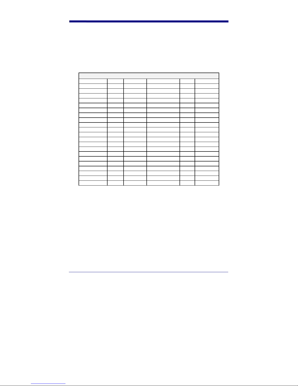
instrument. The following table shows the symbols and their descriptions.
Symbol Description
POWER or Scroll [<>] or
Select
Represents a button on the Quick Check
unit
-Specs- or OK-to-Scan Shows the LED display on the Quick
♦
Check unit
Indicates steps to follow to perform a
procedure
QC200 “Low Battery” Warning
The Quick Check® 200 Series dynamically checks the condition of its battery
when turned on and during menu cycles. If any test falls below a specified limit,
the LCD will show “Low Battery” (and the unit “beeps” five times) as a warning
that the battery’s charge may be deteriorating. The QC200’s microprocessor
“sets” a system “flag” or “pointer” that indicates a degraded condition was
measured for that particular test. With this “flag” set, further cycling of the menu
1
Page 8

or attempts to scan will automatically bring about additional “Low Battery”
indications.
This testing sequence has a power drain than normal scan or single menu
functions. This protects the user by insuring a low battery indication before total
unit power failure occurs, thus preserving proper unit operation. It is possible for
an intermittent “false” low to be detected and reported due to variations in battery
condition, temperature, component efficiency and rapid cycle time. When “Low
Battery” is indicated, the operator should turn their QC200 off, allow one or two
minutes for the battery to recover and then turn it back on. This sequence clears
the Low Battery “flag” or “pointer”. If the “Low Battery” indication returns
immediately on power up, then the unit should be recharged. If not, the QC200
can continue to be used.
The QC200 can be recharged before the warning is seen. Alternately, it can be
left connected to the charger when not in use. To extend battery life, battery
manufacturers recommend you fully charge the unit, use it till the “Low Battery”
indication is seen repeatedly, and then fully recharge before continued use.
2
Page 9

2. Overview
The Quick Check® 200 Series is one of the Hand Held Products family of Quick
Check bar code quality assurance devices. The Quick Check
®
200 Series is fully
portable and compatible with all major bar code symbologies. It is effectively two
instruments in one, both an easy-to-use Pass/Fail quick tester and a powerful
measuring tool for detailed testing and analysis of those same symbols.
®
Testing criteria within the Quick Check
200 Series is based on the American
National Standard X3.182-1990 “Bar Code Print Quality Guideline.” The Quick
Check family of bar code verifiers was designed specifically to fully implement
this guideline guaranteeing symbol compliance to the standard. They provide a
baseline in measurement accuracy against which all verifiers, new and old,
should be judged.
The QC200 series determines print quality, wide to narrow ratios, print contrast
and reflectance parameters, decodes and verifies character format as called for
by application specifications. The quality information from the Quick Check
®
200
Series is presented through an easy to read liquid crystal display (LCD), light
emitting diodes (LEDs), audible tones and through its optional accessory printer.
The knowledge gained using the Quick Check
®
200 Series measurement modes
is invaluable in educating the user about the critical optical characteristics of bar
code symbols.
®
The Quick Check
200 Series can verify the quality of:
• EAN/UPC family of symbols with or without addendum
• Code 39 with or without check character
• Interleaved 2 of 5 with or without check character
• Codabar/USS Codabar with or without check character
• Code 128 with all modes and characters displayed
• MSI Code
• Code 16K
• IATA 2 of 5
• Regular 2 of 5
3
Page 10

Unpacking
When you first receive your Quick Check® 200 Series unit, you should carefully
unpack it. Before attempting to use the instrument, inspect the contents of the
package for any shipping damage. If there is evidence of shipping damage,
please keep ALL packing materials and contact the delivery carrier AS SOON AS
POSSIBLE for claim procedure. Confirm that you have the following items:
QC200 Series model number ordered.
AC Charger
User’s Guide
Manual Pack with:
Test Symbols
Warranty Card
Gauge Ruler
“X” Dimension Ruler
Please fill out the Warranty Card immediately. Also make a note of the serial
number of the unit and the date purchased.
Charging the Battery
NOTE: The battery you received with your Quick Check® 200 unit may be
discharged. Prior to initial use, the batteries should be charged for at least six (6)
hours. The Quick Check
NiCad rechargeable battery pack. It is not intended to be powered directly from
an adapter or AC outlet. The Quick Check
make maximum use of its battery power. As a result, the unit will operate for a
minimum of one (1) hour on a properly charged battery pack.
®
200 unit is designed to operate only using the supplied
®
200 Series verifier is designed to
!!! WARNING!!!
DO NOT CONNECT YOUR QUICK CHECK TO ITS CHARGER OR PRINTER
UNLESS A BATTERY PACK IS INSTALLED. TO DO SO WILL DAMAGE THE
UNIT AND VOID ITS WARRANTY!! ALL UNITS HAVE HAD A PACK
INSTALLED AT THE TIME OF MANUFACTURE.
USE ONLY A HAND HELD PRODUCTS SUPPLIED NICAD TYPE
RECHARGEABLE BATTERY PACK. USE OF OTHER PACKS OR BATTERIES
AND ATTEMPTS TO RECHARGE THESE BATTERIES COULD CAUSE THE
BATTERIES TO EXPLODE, CAUSING DAMAGE TO THE UNIT AND
POSSIBLE PERSONAL INJURY!! DAMAGE CAUSED BY ATTEMPTS TO
RECHARGE OTHER THAN THE SPECIFIED HAND HELD PRODUCTS QC200
4
Page 11

SERIES BATTERY PACK WILL VOID ANY AND ALL QUICK CHECK® 200
SERIES WARRANTIES.
To charge the batteries:
1. Plug the AC charger into the power jack on the end of the Quick Check unit.
2. Plug the AC charger power unit into an appropriate VAC wall outlet.
3. Charge the batteries for a minimum of six (6) hours.
After allowing the proper battery charge time, your Quick Check will be ready for
operation.
If you experience any problems during this set up procedure, carefully review the
above steps and try again. If you still have problems, contact your dealer or
Hand Held Products for assistance.
Command Code “Quick Start”
The Quick Check® 200 Series is a complete, self-contained handheld bar code
verifier. Though we recommend you become thoroughly familiar with the device
and this manual before use, those familiar with bar code verification can easily
set-up and use the QC200 within a matter of minutes (after it has been unpacked
and initially charged) following the next steps:
1. Carefully unpack and inspect the unit. (See section titled UNPACKING for
details)
2. Plug the QCAC charger into the QC200 and an AC wall outlet and charge
the unit for a minimum of six hours. (See sectional titled CHARGING THE
BATTERY for details)
3. After charging, turn the unit on by pressing and releasing the POWER
button. You should hear four beeps indicating the unit is ready.
4. Next, select one of the following pre-printed “Quick Start” Command Codes
appropriate for your use of the QC200, carefully place the tip of the QC200
on the Command Code of choice and scan the code.
5. The unit will respond with four beeps and return to the start up, ready to
scan state.
6. You have now totally programmed your QC200 and are ready to scan your
sample codes. After each scan, the custom LCD display will show decode,
symbology type, PCS or ANSI grade, bar growth/shrinkage indication and
any parameter areas where errors exist. If the code has passed all tests,
one beep will be heard and the green LED will flash. If errors have been
found, three beeps will be heard, the red LED will flash and one or more of
the parameter areas will be lit on the LCD (DIM, REF and /or FMT) to show
in what test criteria area(s) the fault exists.
Detailed information on proper scanning techniques and unit use can be found
throughout this manual. If you have any problems during your “Quick Start,”
5
Page 12

please refer to the rest of this manual or call Hand Held Products’ Customer
Support.
NOTE: Display Orientation (Right Handed vs. Left Handed) and Printer Interface
selection ARE NOT set using the Command Code. Factory default settings for
these are “Right Handed” and “QCHSP”.
.
6
Page 13
3. Detailed Operation
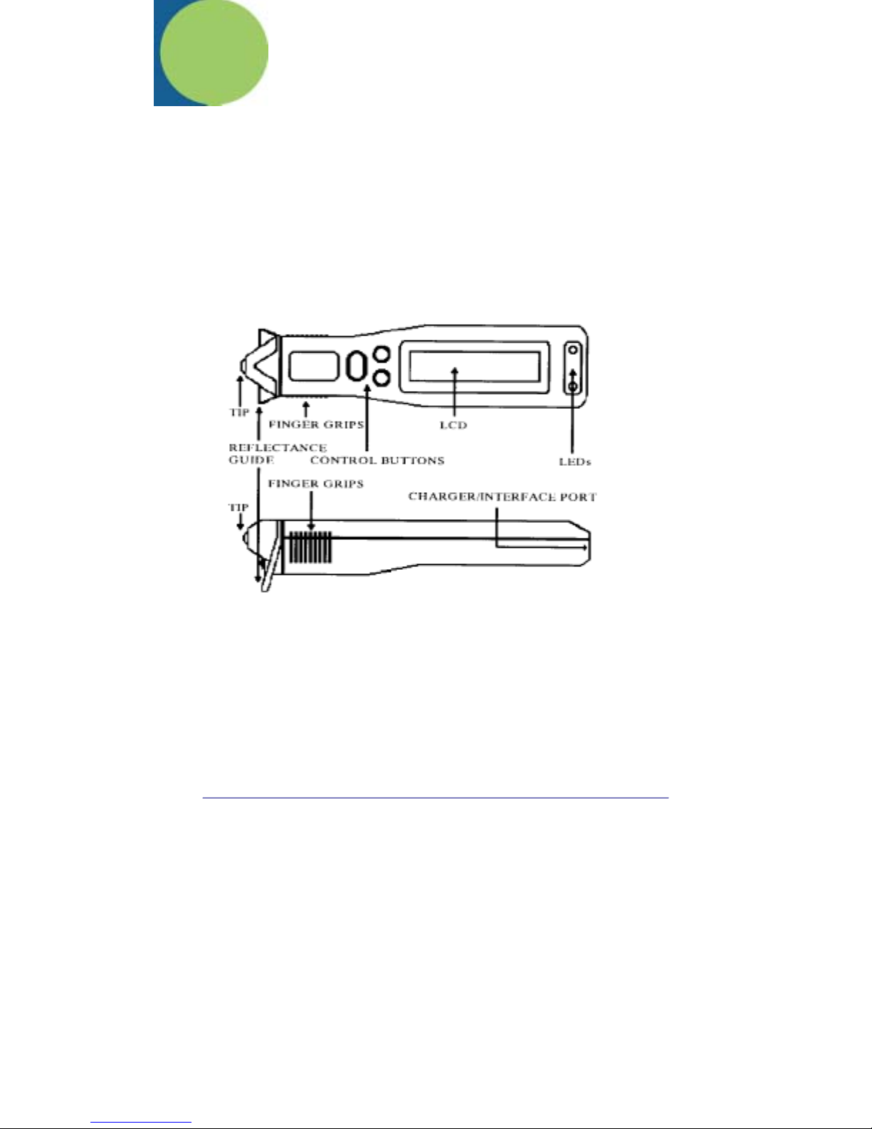
The Quick Check® 200 Series is a complete, self-contained handheld bar code
verifier. The top panel features include a “POWER” button a “SELECT” button
[0], a “SCROLL” [<>] button, a red and a green colored LED and a custom, multifunction, liquid crystal display (LCD). On the bottom of the instrument is the
Serial Number label as well as two of the three case screws that must be
removed for access to the internal battery. (WARNING: DO NOT attempt to
replace the battery pack without first contacting Hand Held Products’ Service
Department!) A port on the end allows connection to a recharger or optional
printer. The following figures show the unit’s layout.
Figure A
7
Page 14
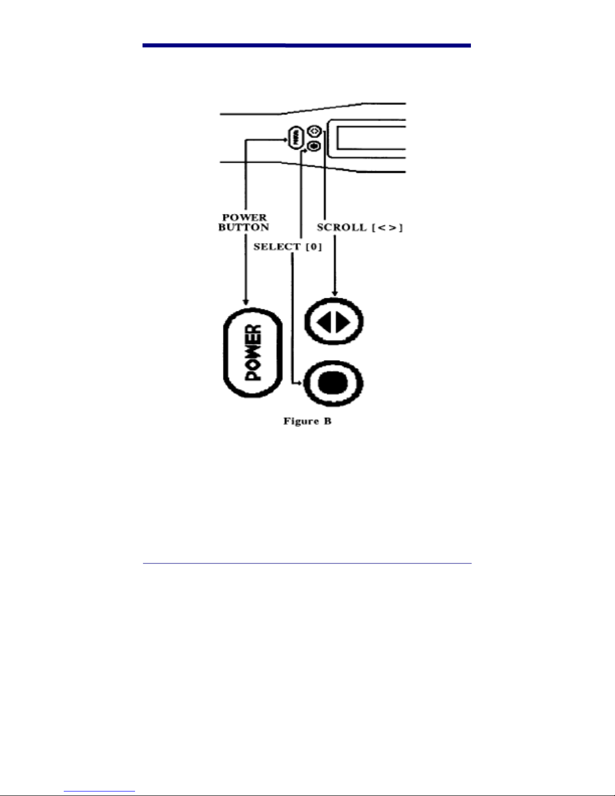
Quick Check® 200 Control Buttons
8
Page 15

Using the QC200
Before you turn the unit on and select a mode of operation, you should review
the following to learn how to properly scan a bar code with it.
To scan a bar code:
1. Hold the QC200 as you would a pen or pencil. The raised “finger grip
ridges” on each side of the case near the optics/scanning tip are guides for
finger placement.
2. Press the optics tip lightly against the surface to be scanned in the clear
area (quiet zone) on either side of the bar code symbol. To maintain a
proper scanning angle, be sure both the optics tip and the “reflectance
guide” are flat on the surface to be scanned.
3. At about the same speed with which you would quickly underline one of the
sentences in this text, and without interruption, move the QC200 evenly
across the center (or approximate center) of the bar code.
4. Listen for a long beep tone quickly followed by a short beep tone signifying a
good read. Note that a long beep followed by three short beeps indicates an
error condition exists in the symbol scanned.
NOTE: Practice your scanning technique until you can successfully scan each of
the supplied test symbols on each attempt. Some of the supplied test symbols
have “intentional errors” in them to show the user how error conditions are
reported.
Power ON/OFF
The Quick Check® 200 Series is turned on by pressing the POWER button, to
which it responds by emitting four quick beeps and first displays:
[QC2xx aa/lll]
where “xx” identifies the model number, “aa” is the aperture size designation in
“mils” (one thousandths of an inch) and “lll” is the spectral response or
wavelength of illumination in nanometers. If there are stored print records (and
the unit is connected to a Quick Check
the display then changes to:
[BUF xx% Ful>]
or it may read “LOW BATTERY!” or “RECALIBRATE!” if charging or reflectance
calibration is needed.
®
AC Charger or Printer interface cable),
9
Page 16

The Quick Check® 200 Series shuts itself off after about a minute of inactivity.
Alternately, the operator can shut the instrument off by pressing the button for
about two seconds, until it beeps and clears the display.
Reflectance Scale Calibration
The first time you use the unit or charge the battery pack and periodically during
normal operation, the Quick Check
calibrated. Remove the QC200 Reflection Calibration Page (QCRFPG) from the
manual and, with the unit at the proper scanning angle (so it rests on its
“reflectance guide”), CAREFULLY scan the reference target symbol 10 times.
Note that your first scan will yield a “triple” beep (one long, two short) as well as
your tenth scan.
®
200 Series reflectance scale should be
NOTE: TO INSURE MAXIMUM REFLECTANCE-SCALE ACCURACY FOR THE
HIGHEST ACCURACY IN DATA COLLECTION, YOUR QUICK CHECK
PERFORMS A CONSISTENCY TEST WHILE THE TEN CALIBRATION SCANS
ARE MADE. IF, DURING THOSE SCANS, IT DETECTS REFLECTANCE
READINGS SIGNIFICANTLY DIFFERENT FROM THE PREVIOUS ONES
RECORDED, IT WILL AGAIN “BEEP” THREE (3) TIMES AND THE LCD WILL
PROMPT YOU TO AGAIN BEGIN THE REFLECTANCE CALIBRATION
PROCEDURE. IF DURING THE MEASUREMENT OF A SAMPLE SYMBOL AN
“XX” or “- -“ IS DISPLAYED OR PRINTED A REFLECTANCE VALUE, AND
OUT OF RANGE READING HAS BEEN MADE. THE UNIT SHOULD BE
RECALIBRATED AND THE SAMPLE SHOULD BE RESCANNED.
Initial Power Up Default Settings
The Quick Check® 200 Series powers up in whatever operating mode it was last
left in. To facilitate “getting started”, we have programmed the QC200 so that it
will default, the first time it is powered up and calibrated, to the settings listed.
The many possible variations available to the QC200 user will be outlined in later
sections of this guide.
All codes Active (Auto-discrimination)
Those Codes are:
Code 39
Interleaved 2 of 5
EAN/UPC 100% Magnification
Codabar
Code 128
MSI
16K
10
Page 17

Other Configuration Settings:
“NormalAccur” – Normal Accuracy
“Trad’l P/F” – Traditional Tolerance Testing
“Avg DMargin” – Hand Held Products Averaged Decodability Margin
“Ltr. Grades” – If ANSI is invoked, Letter Grades used
“Right Handed” – LCD Right Hand Orientation
“HS Printer” – Printer Interface set for Hand Held Products QCHSP
An explanation of each of the above default settings can be found in the
CONFIGURATION/PROGRAMMING section.
11
Page 18

12
Page 19

4. Configuration/Programming
The Quick Check® 200 Series auto-recognizes or “autodiscriminates” seven bar
code symbologies - - Codabar, Code 39, Interleaved 2/5, EAN/UPC, Code 128,
MSI Code and Code 16K - - or alternately can check that symbols conform under
any or all of several applications specifications; AIAG, BOOKLAND, CCBBA,
Comp Tia/CTIA, SCC, SISAC, U.P.C.-COUPON CODE, dependent upon the
QC200 Model. The QC200 also has a number of operator selectable test and
configuration options. The QC200 user can program their unit for all of these
options in two distinct ways. One is by simply scanning a specialized Code 128
called a Command Code. Predetermined Command Codes were used in the
QC200 Quick Start section of this manual and are explained in a later section.
The QC200’s options can also be programmed manually.
®
The “heart” of the operation and manual programming of the Quick Check
Series is centered around its “Select” and “Scroll” buttons. All functions with the
QC200 are controlled by their use. Generally, pressing the Select [0] Button
moves the user from menu “level” to menu “level”. Pressing of the Scroll [<>]
Button allows the user to pick an option within these levels. At the end of the
manual are menu “flow charts” of the QC200 menu sequences. An explanation
of what programmable selections are available follows.
200
Codes/Symbology Options
The Quick Check® 200 Series symbology selection configuration is set and
controlled from within the QC200’s programming menu structure, this is entered
after power up by pressing the Select [0] Button two times as demonstrated
through the next steps:
On power up, [Qc2xx aa/lll] is displayed.
If you press the Scroll [<>] Button the results of the last scan is displayed (the
QC200 always stores the last sample scan). If you press the Select [0] Button
the following is displayed:
[Reflectom’r>]
This is the QC200’s static Reflectometer option, which is described later in this
manual. Pressing the Select [0] Button again bypasses this and changes the
LCD to:
13
Page 20

[- Specs - >]
The “>” indicates to the user that pressing the Scroll [<>] Button will allow them to
select between the different code “specifications” (generic symbologies vs.
applications) preprogrammed into the QC200. If you press Scroll [<>] here, you
are put into the “Codes” (generic symbologies) mode with a resulting LCD of:
[ - Codes - >]
Here you will be allowed to make certain modifications in the testing criteria used
for the generic symbologies. These choices are also accepted or by-passed
using the Select [0] and Scroll [<>] buttons. Pressing Select [0] will bring up the
first set of options:
Codabar Options displayed on the LCD are:
[USS – Codabr>] or [Trad Codabr>]
This choice is between the original constant character width Codabar font (with
Monarch’s original print tolerances applied) and the compatible “rationalized” font
described in AIM’s USS – Codabar specification (with the appropriate USS
tolerances applied). NOTE: An “x” shown during Codabar decoding indicates a
missing stop/start character.
Code 39 Options displayed on the LCD are:
[Cod39 no Ck>] or [Code39 w/Ck>]
This choice is whether to test for Code 39’s optional Mod 43 Check Character
(see AIM USS for Code 39).
Interleaved 2/5 Options displayed on the LCD are:
[Int25 no Ck>] or [Int25 w/Ck>]
This choice is again whether to test for an optional Interleaved 2/5 Mod Check
Character.
UPC/EAN/JAN Options displayed on the LCD are:
[UPC/EAN x.x>] where “x.x” represents a UPC/EAN magnification factor.
The possible choices are .80, .85, .90, .95, 1.0, 1.2, 1.4, 1.6, 1.8 or 2.0 and are
cycled through by repeatedly pressing the Scroll [<>] Button. The default setting
is 1.0 or 100%.
Code 128 Options displayed on the LCD are:
[Cd128 Modes>] or [Cd128 Messg>]
This choice is whether or not to have Special Extra Characters displayed and
printed within the encoded message that show Code 128’s Starting Mode, Mode
14
Page 21
Changes and Shifts. Normally this information is totally transparent to the user
but it may assist in analyzing reading or printing problems.
When scanning Code 128 in the “Show Modes” setup, the LCD display and the
printer “show” Code 128’s “Special Extra Characters” as well as information on
the symbol’s check digit. Because of the nature of some of these characters,
they are represented by special character “strings” as shown in the following
table.
CODE 128 CHARACTER TRANSLATION TABLE
CHARACTER LCD PRINTER CHARACTER LCD PRINTER
00(NUL) 0 <NL> 15(NAK) 15 <NK>
01(SOH) 1 <SH> 16(SYN) 16 <SY>
02(STX) 2 <SX> 17(ETB) 17 <EB>
03(ETX) 3 <EX> 18(CAN) 18 <CN>
04(EOQ) 4 <ET> 19(EM) 19 <EM>
05(ENQ) 5 <EQ> 1A(SUB) 1A <SB>
06(ACK) 6 <AK> 1B(ESC) 1B <ES>
07(BEL) 7 <BL> 1C(FS) 1C <FS>
08(BS) 8 <SC> 1D(GS) 1D <GS>
09(HT) 9 <HT> 1E(RS) 1E <RS>
0A(LF) A <LF> 1F(US) 1F <US>
0B(VT) B <VT> 7F(DEL) * <DL>
0C(FF) C <FF>
0D(CR) D <CR> FCN1 F1 <F1>
0E(SO) E <SO> FCN2 F2 <F2>
0F(SI) F <SI> FCN3 F3 <F3>
10(DLE) 10 <DE> FCN4 F4 <F4>
11(DC1) 11 <D1> Mode A A <A:>
12(DC2) 12 <D2> ModeB B <B:>
13(DC3) 13 <D3> ModeC C <C:>
14(DC4) 14 <D4> Shift Sh <Xh>
* - No “special” displayed character for <DEL>
Code 16K Options displayed on the LCD are:
[Cd16K Modes>] or [Cd16K Messg>]
Selection here is similar to that described under Code 128. When scanning a
Code 16K symbol, the QC200 reports quality information on each individual row
of the code. After the appropriate number of rows has been decoded, the QC200
will also output the complete Code 16K encoded message. Note that Code 16K
uses many of the same special character “strings” as those listed for Code 128.
An additional character, the “Pad” character is shown as Pd on the LCD and
printouts.
15
Page 22

MSI Code Options displayed on the LCD are:
[MSI NoUsrCk>] or [MSI Mod10Ck>] or [MSI Mod11CK>]
which allows the selection of no user specified second check digit or a user
specified second check digit of either the Modulo 10 or Modulo 11 type.
NOTE: The MSI “System” Check Digit, which is inherent to the code, is displayed
on the Quick Check’s LCD line after decode. In some cases it may not be shown
as a “human readable” digit on printed samples.
If, after the initial LCD output of “- Codes - >”, the Scroll [<>] Button is pressed
twice, the operator is then prompted to select an application specification.
“Application”/Model Options
A QC200 is preprogrammed with Industry Applications according to the Model
selected. These application tests not only test the codes for generic print quality
parameters, as applied by the applications, but also test for application specific
formats, check characters and data identifiers. The selection of an application is
accomplished by turning on the QC200.
[QC2xx aa/lll] where “xx” identifies the model number.
Continue by pressing the Select [0]button two (2) times.
[ - Specs - >] is displayed.
Press the Scroll [<>] button
[ - Codes - >] is the next display.
Continue by pressing the Scroll [<>] button until the Industry Application of choice
is display. (message displays for each application are listed below.) Then press
the Select [0] button to accept this Industry Application. NOTE: Only one (1)
Industry Application may be selected at a time.
The available Industry Applications to select from include;
AIAG [ - - AIAG - - >] – Automotive applications
BOOKLAND [ - Bookland - >] – Book applications
CCBBA [ - CCBBA - >] – Blood Bank applications
Comp Tia/CTIA/ABCD [ - - ABCD - - >] – Computer applications
HIBCC [ - HIBCC - >] – Health Care applications
LOGMARS [ - LOGMARS - >] – Government applications
SCC[ - - - SCC - - - >] – Retail (SCS/ITF, EAN-128, UCC 128 Serial)
16
Page 23

SISAC [ - SISAC - >] – Serial Coding applications
U.P.C. [ Coupon Code >] – Coupon Coding applications
If additional user information must be input when an application is selected, the
user will be prompted to do so after the Select button [0] has been pressed.
Those applications need additional input follow:
AIAG the user must indicate whether they are the “supplier” of the bar code or
the “customer” receiving the bar code (the AIAG application specification adjusts
acceptance criteria accordingly).
[AIAG Custmr >] or [AIAG Supplr >]
Pressing the Select [0] Button accepts the choice, the Scroll [<>] Button
bypasses.
SCC This application requires the entry of a magnification factor for the
Interleaved 2/5 symbols to be tested (thereby setting appropriate tolerances!).
The user steps through the choices (>75%, 74%, 70%, 66%, 62%, 58%, 54%,
50%) using the Scroll [<>] Button. Selection is made using the Select [0] Button.
BOOKLAND As with the UPC/EAN/JAN codes mentioned earlier, the Bookland
codes (which are based on those symbols) require input of a magnification factor.
Again, the possible choices are .80, .85, .90, .95, 1.0, 1.2, 1.4, 1.6, 1.8 or 2.0 and
are cycled through by repeatedly pressing the Scroll [<>] Button. Default is 1.0
or 100%.
Model Selections:
QC200 – Symbologies only
QC210 – Retail Model. Symbologies plus retail/book industry applications.
(SCC;BOOKLAND;SISAC)
QC220 – Health Model. Symbologies plus health industry applications.
(SCC;HIBSS;CCBBA)
QC230 – Industrial/Government Model. Symbologies plus
industrial/government.(LOGMARS;AIAG;ABDC/CTIA;SCC)
QC250 – All Industry Applications plus Symbologies
“Tests” Options
After Power up and pressing the Select [0] Button three times, you are brought to
the “Test” Programming Sections:
17
Page 24

[ - Tests - >]
Pressing the Scroll [<>]Button once at this point will access the area of the
QC200’s programming where test procedures are determined. Use of the Select
[0] and Scroll [<>] buttons here will allow you to select the unit's pass/fail level
criteria (Traditional vs. ANSI), use of a higher level of statistical accuracy for
measurement of each scan path (NormalAccur vs. ExtendAccur), type of
Decodability calculation to use (Avg DMargin vs. Decodability) and whether,
when ANSI is the pass/fail criteria, letter or number grading is used (Ltr. Grades
vs. Num. Grades). An explanation of these possible selections follow.
“Trad’l P/F” vs. “ANSI PrQual> A” / “ANSI PrQual> B”/ “ANSI PrQual?
C”/”ANSI PrQual> D” The Quick Check
®
200 Series can apply Pass/Fail
criteria based on either the “Traditional” bar code print tolerances and PCS
measurements or the “Graded” methodology specified in the ANSI Standard “Bar
Code Print Quality – Guideline” X3.182. Upon any measurement scan, the
QC200 beeps either once to indicate a passing symbol or three (3) times to
indicate failure of one or more tests. Choose here whether to apply Traditional
Pass/Fail criteria -- PCS value and Print Tolerances – or the graded <A> through
<F> criteria and scales from ANSI’s Print Quality Guideline.
®
“NormalAccur” vs. “ExtendAccur” The Quick Check
200 Series is capable of
scanning in a “Normal Accuracy” mode as well as in “Extended Accuracy”. In the
“Extended Accuracy” Mode, ALL individual parameter measurements and results
are averaged over eight (8) successive scans of a given scan path of the symbol
under test, greatly reducing reading variability due to variations in scanning
motion and minor scan path variations. This is not to be confused with ANSI’s
recommended ten (10) scan symbol average, where ten (10) individual symbol
scans have their final scan grade averaged.
“Avg DMargin” vs. “Decodability” “Decodability” is an ANSI graded measure
of how close a given scan comes to a reference decode failure due to variations
in the bar and/or space widths. The Quick Check
®
200 Series has the ability to
analyze a symbol using “Decodability Margin” (Avg DMargin in the QC200) as
well as true “ANSI” Decodability (Decodability in the QC200). “Decodability
Margin” is the character-averaged value of Decodability. Decodability is what
percentage of the symbology’s safe decoding margin is left for the scanner after
printing errors. Lower margin values and corresponding lower grades indicate an
increased susceptibility to decoding failure due to scanning errors such as, for
example, acceleration or bar or space size deviations. NOTE: Variations in scan
speed affects ANSI Decodability. When hand scanning set this option to “Avg
DMargin”. “Decodability” (ANSI Decodability) should only be used by those
who have a very consistent and smooth scanning action or with automated
scanning. The QC200 will “measure” your scanning and prompt you to “Scan
Faster”, “Scan Slower” or “Scan Evenly” if it detects gross variations in your scan
rates.
18
Page 25

“Ltr. Grades” vs. “Num. Grades” When the QC200 has been set to an ANSI
grade for its test criteria, the user can have that ANSI grade reported as a letter
or as a number ( 4.0=A, 3.0=B, 2.0=C, 1.0=D and 0.0=F) by selection either “Ltr.
Grades” or “Num. Grades” here.
“Config.” Options
After Power up and pressing the Select [0] Button four times, you are brought to
the “Config.” Programming Section:
[ - Config. - >]
Pressing the Scroll [<>] Button once at this point will access the area of the
QC200’s programming where reporting configuration is determined. Use of the
Select [0] and Scroll[<>] Buttons here will allow you to select the unit’s LCD
orientation (Left Handed vs. Right Handed), raise or lower the beeper pitch or
effect volume (Raise Pitch in single steps or Lower Pitch in single steps), select
the Hand Held Products QC printer (HS Printer, VHS Printer or Std Printer) and
finally save the settings in non-volatile RAM for future use. An explanation of
these possible selections follows:
“Left Handed” vs. “Right Handed” The QC200’s custom LCD display can have
its text and read-outs oriented for either a left handed or right handed user. This
automatic “flipping” of the LCD image makes the unit easy to use and read by all
operators. Selection of either orientation is done here by pressing the Scroll [<>]
Button.
“Raise Pitch” Repeated pressing of the Scroll[<>] Button increases the
pitch/volume of the QC200 beeper.
“Lower Pitch” Repeated pressing of the Scroll[<>] Button increases the
pitch/volume of the QC200 beeper.
®
“Std Printer” vs. “HS Printer” vs. “VHS Printer” . The Quick Check
Series supports all three of Hand Held Products’ accessory printers. The QCP,
QCHSP and QCSSP printer interface software is selected here by pressing the
Scroll [<>] Button until the desired setting is shown on the LCD.
To save these settings and the other previous selected options, the user again
presses the Select [0] Button after leaving the desired accessory printer selection
on the LCD. This brings the following message to the LCD:
[SaveSetngs?>]
Pressing the Select [0] Button will by-pass this (effectively answering “NO”), but
pressing the Scroll [<>] Button will accept it, changing the LCD to:
200
19
Page 26

[**Confirm**>]
This gives the user a last chance to change their minds and abort the changes.
Again, pressing Select [0] will by-pass it, but pressing Scroll[<>] will accept it
changing the LCD to:
[ - Busy! - ] then to [Version yyyy] and finally to [QC2xx aa/lll]
as the non-volatile memory is updated. The “yyyy” represents the base
software’s “checksum”. This number can be used by Hand Held Products’
Service Department when identifying a QC200. (If the Select [0] Button is
pressed after “SaveSetngs?>” or “**Confirm**>”, the LCD changes automatically
to the “Version yyyy” message.
20
Page 27
5. Symbol Testing & Scan Results
The Quick Check® 200 Series acquires data during a measurement scan utilizing
the new software-intensive “ScanProfile” methodology as specified in ANSI’s
“Bar Code Print Quality Guideline” (ANSI x3.182). (NOTE: In all cases, the
more smooth and slow the scan, the more accurate the results.) the user may be
prompted with a series of beeps (one long and three short) and one of the
following displays:
[Scan Slower!] or [Scan Evenly!] or [Scan Faster!]
indicating that the scan was either too fast, too uneven/erratic or too slow for
proper data collection. A practiced, more deliberate and smooth rescan should
be made to insure accurate results.
Both pass/fail testing and detailed measurements on a given symbol are
obtained simply by scanning across it with the QC200. The most accurate
results will be obtained by starting just outside the quiet zone and scanning in a
single, smooth motion with the optics tips and reflectance guide “foot” lightly
touching the symbol surface. Practice helps! A successful measurement will be
signaled by beeping, a blinking green (pass) or red (fail) LED and the display
showing results such as:
21
Page 28

If in Traditional P/F Test Mode. When in ANSI Grading Test Mode, the PCS
value shown is replaced with an ANSI letter grade or its numerical equivalent.
A symbol that consistently produces no beeping is either fatally out-of-spec or of
an unknown or unprogrammed bar code symbology.
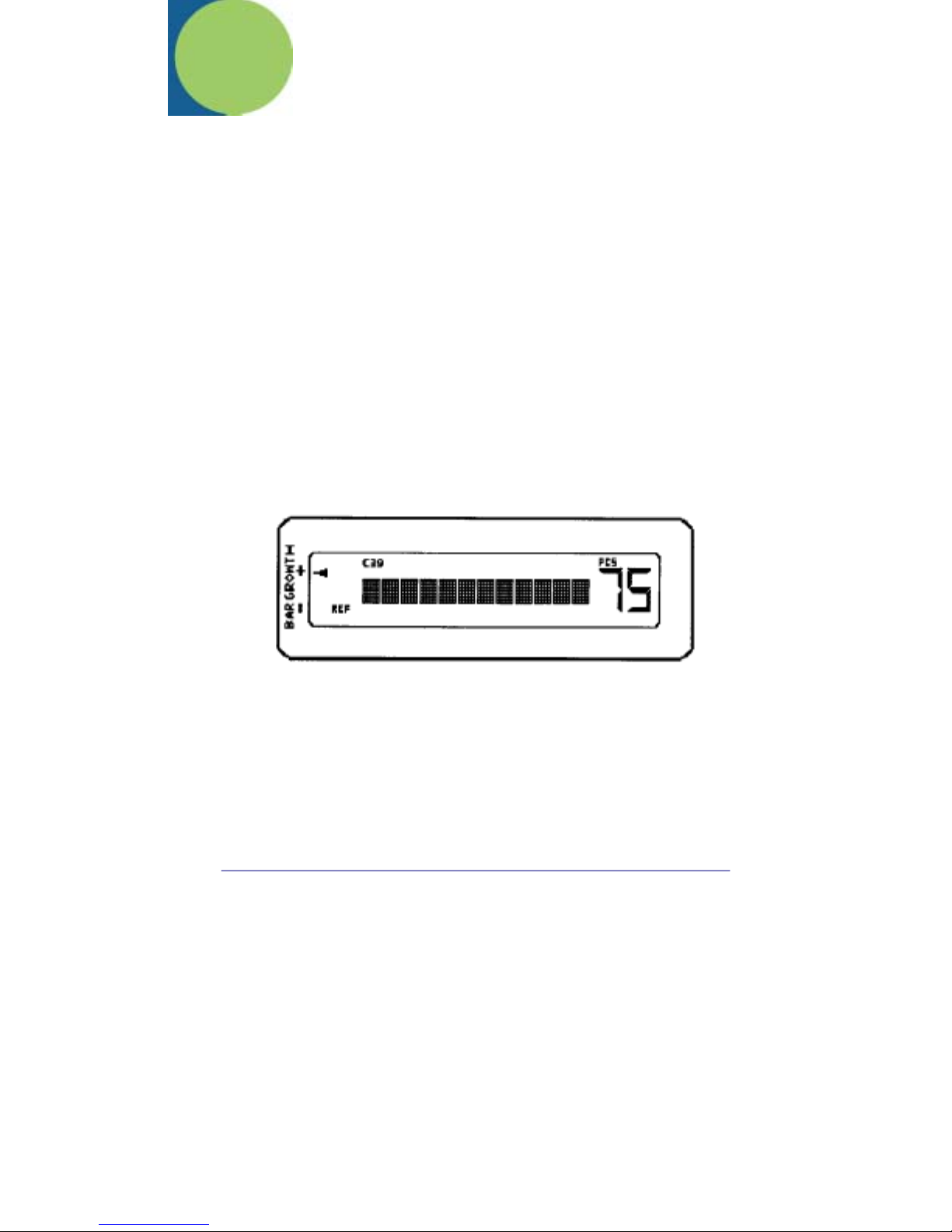
The QC200’s customer LCD display shows the user a complete synopsis of the
scan results. The information shown includes the decode of the symbol’s
encoded characters (dot matrix characters in the middle of the LCD), the
symbology type (across the LCD top), the PCS or ANSI Grade (on the right when
in the Right Handed viewing orientation), an indication of bar growth/shrinkage
(small arrows to the extreme left of the LCD when in the Right Handed viewing
orientation) and in what parameter any error may have occurred (the key words
DIM, REF and/or FMT will light just to the left of the symbol decode, when in the
Right Handed viewing orientation).
If the encoded message in a bar code symbol exceeds 12 characters, the right
most character of the display will be a “right arrow” (>). In that case, pressing the
Scroll[<>] Button will “scroll” the encoded message and allow the remainder of
the message, in 11 character portion, to be viewed.
As mentioned above, uniform bar growth or shrinkage is displayed by a vertical
series of “arrows” on the LCD. One “arrow” will remain lit to indicate the average
bar width error in relation to traditional print tolerance allowances. When
centered between the “+” and “-“ on the label, the bar growth/shrinkage is at a
minimum. As the arrow position moves toward the “-”, increasing amount of
shrinkage is seen. Conversely, a move toward the “+” indicates bar growth.
When the arrow directly across from either the “+” or “-“ is lit, traditional bar width
tolerances have been exceeded. There are seven arrows in the scale.
With each test scan of a symbol, the QC200 also indicates the sample’s pass/fail
status with a characteristic “beep” pattern. One long beep with ONE short
indicates that the symbol passes the appropriate battery of tests. One long beep
with THREE short beeps indicates that it fails in some regard. Thus pass/fail
testing proceeds by simply scanning symbols and listening for a triple beep.
Upon any failure, the LCD indicates the parameter area where the failure
occurred. These areas are indicated by a three-letter abbreviation.
DIM = a DIMENSIONAL parameter error
REF = a REFLECTANCE (contrast) parameter error
FMT = a FORMAT parameter error
In a symbol with multiple errors, you will have more than one of the above
indicators lit. Exact details of the failure can be obtained by following the
procedures in the section that follows.
22
Page 29

When in the ANSI Grading mode, every tenth measurement of a given symbol
(or every eightieth measurement if also in Extended Accuracy mode) will
cause the results message for the last scan to be replaced with:
[**g/aa/lll**] x.x
reflecting the ANSI Symbol Grade (average of the ten Scan Grades per ANSI
procedures). In this display, “g” is the ANSI Grade (A,B,C,D or F), “aa” is the
verifier’s aperture size, “lll” is the verifier’s spectral response and “x.x” is the
numerical value the ANSI letter grade was derived from.
Test Result Details
Dimensional Parameters
After a successful scan is made, detailed results in the Dimensional Parameters
area are accessed by first pressing the Select [0] Button once. This will produce
the display:
[Dim’l Data>] P (or F)
Either the “P” or “F” will be shown to indicate if the symbol under test passed or
failed the Dimensional Parameters. Pressing the Scroll [<>] Button will move you
into the Dimensional Parameters details. The order the displays are shown
changes dependent upon whether the QC200 is set for “Traditional” or “ ANSI”
testing criteria (though in each case all the same displays are shown). For this
document, the order used with “Traditional” test criteria is illustrated, with the first
display showing:
[AvgBar x.xxX] P (or F)
AvgBar is the average bar print error. It is the value or amount of average bar
growth or shrinkage in the measured symbol relative to its X dimension. This
value is compared against Traditional print tolerance criteria with the “P” of “F”
showing compliance or non-compliance. Pressing the Scroll [<>] Button again
changes the display to:
[W/N Ratio x.xx] P (or F)
W/N Ratio is the wide-to-narrow ratio and is measured for those symbologies
where it is meaningful, namely Code 39, Interleaved 2/5 and USS-Codabar;
otherwise, it is not displayed. This value is compared against either generic limit
(1.8 to 3.2) or a target fixed value (e.g., 2.5 + 0.2) to determine if it passes or
fails. An out-of-range W/N ratio is considered a dimensional error under BOTH
Traditional and Graded testing criteria.
23
Page 30

Another press of the Scroll [<>] Button will display (ONLY IF applicable errors
have been found) certain Global Threshold, Reference Decode or Reference
Algorithm failure messages such as:
[GloThrsFAILS] F or [RefDcod FAIL] F or [RefAlgoFAILS] F
Global Threshold ANSI’s Symbol Grading methodology requires foremost that
a global reflectance threshold set simply at the halfway point between R(min) and
R(max) should “find” every bar and space in the symbol. The Quick Check
®
200
Series uses the ANSI prescribed methodology for precise edge location and
indicates when the global threshold requirement has not been met. “Reference
Decode or Algorithm” ANSI’s Graded symbol testing criteria requires that a
given scan be decodable using certain “reference” algorithms, else the scan fails.
Similarly, certain application specifications call for specific formats, checks or
characters that must be in the symbol. The Quick Check
®
200 Series employs
advanced decoding schemes to test the necessary reference decoding and
algorithms. If any errors are encountered, a failure is indicated appropriately.
If errors were not found in these areas, the next display would read:
[D Margin xx%] Grade or [Decod’ty xx%]Grade
Decodability/Decodability “Margin” Decodability is a Graded measure of how
close a given scan comes to a reference decode failure due to variations in bar
and space widths. The Quick Check
®
200’s “Avg DMargin” is the characteraveraged value of Decodability. Decodability is what percentage of the
symbology’s safe decoding margin is left for the scanner after printing errors.
Lower margin values and corresponding lower grades indicate an increased
susceptibility to decoding failure due to scanning errors such as, for example,
acceleration or bar or space size deviation. Decodability “Margin” is stated as “D
Margin” in the QC200’s LCD Dimensional Details display and ANSI decodability
is listed as “Decod’ty”.
If the Scroll [<>] Button is again pressed, various other Dimensional Parameter
errors might be displayed next. Examples of these follow:
[BAD QuietZon] F -- Indicates insufficient Quiet Zone width
[WIDE IC Gap] F -- Indicates the InterCharacter Gap is too wide
[BAD StrtStop] F -- Indicates either the Start or Stop Characters are bad
[BAD GuardPat] F – Indicates that the Guard Bar Pattern in a UPC/EAN/JAN
symbol is bad
[BAD Separatr] F – Indicates a bad Separator Pattern
Pressing the Scroll [<>] Button again produces the display:
24
Page 31

[Total xxx”X”]
Total xxx”X” indicates the total symbol width expressed in “X” dimensions.
“Formally” a bar code symbol’s width includes the quiet zones, however the value
presented here is a calculated count of the number of “X” dimensions from the
starting bar through the ending bar of the scanned symbol. The operator can use
this value and the symbol’s actual measured width to calculate X. By pressing
Scroll [<>] again, the display becomes:
[Calc “X”? 0]
The “X” DIMENSION can now be calculated by first pressing the Select [0]
Button (pressing Scroll [<>] will by-pass this operation) giving the following
display:
[SymLen=0.--“]
By then entering the symbol’s width as measured with the supplied ruler in
decimal inches (e.g., 1.24), the operator provides the key parameter for
calculating X. To change the value of “0.--“, press the Scroll [<>] Button. This
increments the first digit from “0” to “9”. When the desired digit is shown, press
Select [0] to accept and move to the next digit. After all three are filled in, the
Quick Check® 200 series then calculates the X Dimension and displays it in the
following manner:
[X is x.xxxx”]
If 0.00 is entered, the X remains uncalculated. The “total” width of any EAN/UPC
symbol is that of the main symbol, ignoring a possible addendum.
Reflectance Parameters
After a successful scan is made, detailed results in the Reflectance Parameters
area are accessed either by first stepping through the Dimensional Details as
shown above or by pressing the Select [0] Button twice. This will produce the
display:
[Refl Data >] P (or F)
Again, either the “P” or “F” will be shown to indicate if the symbol under test
passed or failed the Reflectance Parameters. Pressing the Scroll [<>] Button will
move you into the Reflectance Parameters details. The order of the displays are
shown changes dependent upon whether the QC200 is set for “Traditional” or
“ANSI” testing criteria (though in each case all the same displays are shown).
For this document, the order used with “Traditional” test criteria is illustrated, with
the first display showing:
[PCS xx%] P (or F)
and then pressing the Scroll [<>] Button again will give:
25
Page 32

[Rl:Rd xx:xx%] P (or F)
Print Contrast Signal (PCS), Light Reflectance (Rl) and Dark Reflectance
(Rd) are all “Traditional” measures of symbol contrast. PCS is based on the
reflectance of light areas, Rl and dark areas, Rd. These values are determined
using a definition of Rl and Rd as the Peak Light and Peak Dark points seen
during the scan. Thus Rl = R(max) and Rd = R(min) in current terminology. The
Traditional pass/fail criteria are PCS > 75% with Rl > 25% and Rd <30%. NOTE:
IF DURING THE MEASUREMENT OF A SAMPLE SYMBOL AN “XX” IS
DISPLAYED OR PRINTED AS A Rl, Rd or PCS REFLECTANCE VALUE, AND
“OUT OF RANGE” READING HAS BEEN MADE.THE QC200 SHOULD BE
RE-CALIBRATED AND THE SAMPLE SHOULD BE RESCANNED. Again
pressing the Scroll [<>] Button will change the display to:
[SymContr xx%] Grade
Symbol Contrast (SC) is a Graded measure of the difference between the
highest reflectance value R(max) and lowest reflectance value R (min) seen
during a measurement scan. Another press of the Scroll [<>] Button changes the
display to show:
[Rmin/Rmx xx%] Grade
Rmin/Rmx has an additional Pass/Fail (Grade “A” or “F”) requirement that it be
at or below 50%. Press the Scroll [<>] Button again to get:
[Modul’n xx%] Grade
Modulation (MOD) is an ANSI graded criterion equal to Edge Contrast (min)
divided by Symbol Contrast.
[Edge(mn) xx%] Grade
Edge Contrast Minimum (Ecmin or Edge(mn)) is the minimum value of Edge
Contrast (EC) seen during a measurement scan. Edge Contrast (EC) is the
reflectance difference between an adjacent bar and space. The Pass/Fail
requirement (Grade “A” or “F” here is that the EC(min) be >15%. Another press
of the Scroll [<>] Button brings us to the final Reflectance parameter detail of:
[Defects xx%] Grade
Defects is the Graded measure of the maximum Element Reflectance Non-
uniformity (noise WITHIN any element due to spots, voids, etc.) normalized to
symbol Contrast.
Format Parameters
After a successful scan is made, detailed results in the Format Parameters area
are accessed either by first stepping through the Dimensional and Reflectance
Details as shown above or by pressing the Select [0] Button three (3) times.
26
Page 33

[Msg Format >] P (or F)
Either the “P” or “F” will be shown to indicate if the symbol under test passed or
failed the Format Parameters. Pressing the Scroll [<>] Button will move you into
the Format Parameters details. The order the displays are shown changes
dependent upon whether the QC200 is set for “Traditional” or “ANSI” testing
criteria (though in each case all the same displays are shown). For this
document, the order used with “Traditional” test criteria is illustrated. If an
Application Specification has been activated, the normal sequence will be
superseded by the following display:
[APPL *Type*]
where APPL will be the appropriate Application and Type will be any possible
sub-identifier within that application. Repeated pressing of the Scroll [<>] Button
will then show any other application specific errors such as:
[BAD Source]
and will finally come to:
[MsgLength xx] P (or F)
Message Length is the length of an encoded message. The length may need to
be checked against an application-specified length restriction. Another press of
the Scroll [<>] Button displays:
[No Check Chr] P or
[ChkChr Checks] P or
[ChkChr Fails] F
Check Characters may be mandatory under a bar code symbology
specification, required by the user or by an application specification: either,
neither, or both! The display screen will reflect the requirement and the result.
Repeated pressing of the Scroll [<>] Button will reveal any additional error
situations such as:
[BAD Symbology] F if a wrong code type is found.
At this point (or any other point during the scrolling of results), pressing the
Select [0] Button will cycle the QC200 into its “Store” (if not hooked to a printer)
or “Print” (if hooked to a printer) sequence. The print sequence is explained in
Section 6.
27
Page 34

28
Page 35

6. Printer Printout Samples
[Store Data?>]
When a printer is not attached or is turned off, you are asked if you wish to store
the measured results in a 20-scan print buffer. Pressing the
Scroll [<>] Button will store the scan. The buffer’s contents can later be dumped
to the printer. When a QC200, that has stored data, is hooked to a printer and
the QC200 is then turned on, the first display will be a query on whether or not to
dump the stored information. NOTE: The QC200 will also “see” the QCAC
Charger as a “printer” when it is connected.
[Print Data?>]
When a printer is attached to the Quick Check® 200, you are asked if you wish to
print the most recent scan. Pressing the Scroll [<>] Button will cause the current
testing results to be printed and the following display will show:
[ - Busy ! - ]
NOTE: Printing can be halted after starting by momentarily pressing the POWER
button on the QC200. Printing will stop as soon as the printer’s internal buffer is
clear.
29
Page 36

Printout Samples
All of the measurements obtained during a measurement scan are saved in a
temporary buffer. When a printer is not connected those measurements can be
transferred to a 20-scan print buffer as described above. When a printer is
attached and powered, it produces a listing of full measurement details. From a
QCP or QCHSP, the printout would look similar to the following
\\\Quick Check® 200\\\
660 nm, 06 mil Scanner
UPC-A: 100% Mag. Factor
021200074424
Avg Bar Err = +.04X OK!
DecodeMargin = 92% <A>
Symbol Total = 095 “X”
Prnt Contr Sig = 94% OK!
Reflect (Light) = 75% OK!
Reflect (Dark) = 03% OK!
Symbol Contrst = 72% <A>
R(min)/R(max) = 04% <A>
Modulation = 79% <A>
EdgeContr(min) = 57% <A>
“Defects” = 05% <A>
Message Length = 11 OK!
Check Charctr Passes OK!
Traditional Tests <PASS>
Bar Growth: IN TOL (+)
“P C S” – OK
Traditional Tests - PASS -
Format Tests - PASS -
ANSI Parameters <A>
Dimension Checks <P>
Format Checks <P>
Profile QualityGrade <A>
30
Page 37

From a QCSSP, a typical printout would look more like the following:
Quick Check® 200 –
660 nm, 06 mil Scanner
Code 39
*+A123B4C5D6E711*
AvgBar = +.05 X OK! W/N Ratio = 2.9 OK!
DecodMargn = 88% <A> Symbol Totals 264X
PCS = 90% OK! R(L) = 79% OK! R(D) = 07% OK!
SymbolContr = 72% <A> R(mn)/R(mx) = 09% <A>
Modulation = 61% <B> EdgeCtr(mn) = 44% <A>
“Defects” = 04% <A>
Msg Length = 15 OK! -No-Check Character
Bar Growth: IN TOL
“P C S” : OK
Traditional Tests -PASS-
Format Tests -PASS-
ANSI Parameters: <B>
Dimension Checks: <P>
Format Checks: <P>
Profile Quality Grade is <B>
For all printers, on the tenth scan of a given symbol (or eightieth scan if in
“Extended Accuracy” mode), a message similar to the following will be appended
to the normal printout.
31
Page 38

For the QCP and QCHSP:
***************************
* Symbol Quality Grade *
* Avg 4.0 = > A/06/660*
***************************
And from the QCSSP:
*****************************************************
****
Symbol Quality Grade: Avg 3.0 = > B/06/660
*****************************************************
****
Each result shown in the printout is information also available on the display as
previously described. Having the wrong printer setting, if encountered, may
cause printing difficulties. This is set within the “Config.” Menu as explained
previously.
Printing can also be initiated in either a single (“on demand”) or continuous
(“auto-print”) print mode by use of the Printer Control Command Codes found
later in this manual.
NOTE: Printing can be halted after starting by momentarily pressing the
POWER button on the QC200. Printing will stop as soon as the printer’s internal
buffer is clear.
32
Page 39

7. Special Functions
The Quick Check® 200 series can be set to a special “static” reflectance
measurement function (Reflectometer Mode). This mode is especially useful in
investigating the underlying optical characteristics of bar code symbols. The
Reflectometer Mode, along with the Command Code mode is covered below.
Reflectometer Mode
This menu selectable Special Function is entered by pressing the Scroll [<>]
Button when [Reflectom’r>] is present on the LCD. Then in this special
reflectometer mode, the reflectance “seen” by the QC200’s optics is continuously
displays as both a two digit reflectance percentage and on a graphic bar graph
as soon as the mode is invoked.
Here the xx% and the graphic bar graph (or “gas gauge”) represent a reflectance
value of 00% to 100% from the static reflectometer. This mode is not
“memorized” when the unit is shut off. When turning the unit back on after power
down, it will be necessary to re-establish the Reflectometer Mode if needed. For
these values to be meaningful and consistent, it is critical first that reflectance
calibration have been performed recently and second that the QC200 be held
with its “reflectance foot” and optics tip both touching the sample to maintain the
proper angle.
Command Code Programming
The Quick Check® 200 series has the unique ability to be “pre-programmed” by
the user by scanning a specially encoded code 128 symbol. This symbol will
automatically make all the selections normally made by the user stepping
through the normal menu sequence. This is particularly useful if the user has
one or two particular setups that they are constantly switching between.
Samples of Command Codes, such as the Command Code to “reset” the QC200
back to all generic default settings, are included with each unit.
NOTE: Display orientation (Right Handed vs. Left Handed) and Printer Interface
selection ARE NOT set using the Command Code. Factory default settings for
these are “Right handed” and “QCHSP”.
Users with one of the accessory Quick Check® Printers can produce a Command
Code of their QC200’s present set-up by following the next steps;
First be sure your Quick Check
the proper interface selection has been made and both are turned on. Next,
®
200 is connected to a Quick Check® Printer, that
33
Page 40

locate the Special Features Bar Code Menu in the back of this manual. On this
Menu sheet are two codes, Command Code “Unlocked” and Command Code
“Locked”. Scanning either will result in the Quick Check
®
Printer printing the
specialized code 128 you can use for rapid one step programming of your
QC200.
The Command Code “Locked” code allows the user to add a feature to the
Command Code that will “lock” the menu programming after that code is scanned
the first time. This prevents access to reprogramming of the unit by the casual
user. The “lock” can not be removed unless the user scans another, previously
prepared, Command Code that does not have the “lock” function in it, such as
the “reset” Command Code supplied in this manual. (NOTE: Before actually
using this code, label it along the line provided with a description and make a
copy of it on your office copier. This helps improve the bar code quality. Making
a “reduced size” copy will help also.)
These codes are also produced by Hand Held Products. Contact Customer
Administration at Hand Held Products about this service. It will be necessary to
make the following selections;
OPERATING MODE
Extended Accuracy (8-Scan/Scan path average)
ON(ExtendAccur) or OFF(NormalAccur)
Decodability (choose one)
Hand Held Products’ Decodability Margin (Avg DMargin)
ANSI’s (Decodability)
Pass/Fail Criteria (choose one)
“Traditional” P/F (Trad’l P/F) or
ANSI Grades – D, C, B, or A
ANSI Grading by LETTER or NUMBER (choose one)
Letter Grades (Ltr.Grades)
Number Grades (Num. Grades)
Program Menu Lock
On or Off
Reflectometer Mode
On or Off
34
Page 41

SPECIFICATION
Generic Codes vs. Application Spec (choose one)
Generic Codes (if selected an Application cannot also be selected)
Code 39 Yes or No and Mod Check? Yes or No
Interleaved 2 of 5 Yes or No and Mod Check? Yes or No
UPC/EAN/JAN Yes or No
Magnification Factor?_ _ _ (Default is 100)
Choices – 080/085/090/095/100/120/140/160/180/200
Codabar Yes or No
Traditional Codabar? Yes or No
USS Codabar? Yes or No
Code 128 Yes or No and Modes or Messages (choose one)
MSI Code Yes or No
User Check Digit? Yes or No
Mod 10 or Mod 11? (choose one)
Code 16K Yes or No and Modes or Messages? (choose one)
Application Specification
CCBBA Yes or No
HIBCC Yes or No
AIAG Yes or No
Bookland Yes or No
SISAC Yes or No
Logmars Yes or No
CompTia/CITA(ABCD) Yes or No
SCC Yes or No
I 2/5 mag factor? _ _ _ (default 075)
35
Page 42

36
Page 43

8. Quick Check Maintenance
Battery Charging
Charging the battery pack > > when the batteries require recharging, the LOW
BATTERY!! Prompt will flash on the LCD. The unit will not allow further scans
until it has been turned off and the batteries recharge to a level above the
operational minimum. The batteries will only recharge when the Quick Check is
not in use.
To charge the batteries in the unit:
1. Plug the QC charger into the power jack on the end of the Quick Check.
2. Plug the AC charger power cube into an appropriate VAC wall outlet.
3. Charge the batteries for a minimum of six (6) hours.
After following the proper battery charging time, your Quick Check will be ready
for operation.
Scanner Tip Cleaning
Occasionally the scanner tip and its optically clear window may become partially
obstructed by ink, paper fibers or other deposits. To insure reliable scanning,
you should check the tip periodically and clean it if dirty.
To clean the scanner tip:
1. With the Quick Check turned off, lightly dust the tip with a soft camel’s
hairbrush or equally soft device.
2. If ink or deposits are still evident, using a mild cleaning solution and soft
applicator (cotton swab), wipe the tip to clean.
NOTE: Damaged wand tips may be replaced. Contact the Customer
Administration or Service Department for details.
Reflectance Calibration Page Replacement
The Reflectance Calibration Page that comes with your Quick Check® 200 is
used for setting the unit’s reflection calibration point. This page is a precision
made standard. If it should become physically damaged or dirty, it should be
replaced in order to insure proper operation of the unit. Contact Customer
Administration at Hand Held Products to order replacements.
37
Page 44

Troubleshooting
If your Quick Check fails to operate properly after following all operation
instructions carefully, do not open the case or attempt to repair. This will void the
warranty. Contact Hand Held Products for assistance.
38
Page 45

9. Single Scan To Result (SSTR)
Hand Held Products’ Single Scan To Result (SSTR) feature allows the user to
quickly and easily access test results using the following SSTR bar codes,
without having to step through each of the QC200’s individual result menu steps.
After a test scan is completed, the user can find the result they are interested in
by simply scanning the appropriate SSTR Code. If another result is required,
simply scan that SSTR code.
You can set the QC200 to display a particular parameter as the default “first
message” after each test scan by scanning the “INSTALL” SSTR Code, then the
SSTR Code that you desire as your default and finally scanning the “SAVE
SETTINGS” SSTR Code twice.
By installing the “First Failure” SSTR Code as the default, your QC200 will
display as its default first message, whichever parameter fails “first” on a test
scan. The order of test/failure is the same order as that of the parameters listed
in a QC200 printout. See the “PRINTOUTS” section of this manual.
Installing the “Decode” SSTR Code will reset the QC200 to factory default report
settings.
NOTE: All parameter test results are still accessible by using the QC200’s
Select [0] and Scroll [<>] buttons as outline in the “TEST RESULT
DETAILS” section of this manual.
39
Page 46

40
Page 47

10. Printer Information
Saving Data
When you scan a bar code symbol, and you do not have a printer connected to
the Quick Check, or it is connected by not turned on, the Quick Check can save
the measured data in its temporary buffer. You can send scan results to this
temporary buffer by using special Print/Store Codes or stepping through the
menus. Later you can send this data to a printer.
When a printer is attached to the Quick check and turned on, you can print the
results stored in the buffer or, if the buffer is empty, the current results, using the
special Print/Store Codes or stepping through the menus.
When you turn on the Quick Check and the buffer has stored data or you fill the
buffer during use, the display will tell you. You can print or delete the stored
records. Instructions are provided later in this section.
Reviewing printouts
The Quick Check can print to three Quick Check printers. The printouts from the
QCP and QCHSP look similar while the printout from the QCSSP looks different.
Both types are shown in the Figure 10-1.
Figure 10-1 QCP and QCHSP Printers
41
Page 48

Figure 10-2, QCP and QCHSP printout
\\\Quick Check® 200\\\
660 nm, 06 mil Scanner
UPC-A: 100% Mag. Factor
Avg Bar Err = +.04X OK!
DecodeMargin = 92% <A>
Symbol Total = 095 “X”
Prnt Contr Sig = 94% OK!
Reflect (Light) = 75% OK!
Reflect (Dark) = 03% OK!
Symbol Contrst = 72% <A>
R(min)/R(max) = 04% <A>
Modulation = 79% <A>
EdgeContr(min) = 57% <A>
“Defects” = 05% <A>
Message Length = 11 OK!
Check Charctr Passes OK!
Traditional Tests <PASS>
Bar Growth: IN TOL (+)
Traditional Tests - PASS -
Format Tests - PASS –
ANSI Parameters <A>
Dimension Checks <P>
Format Checks <P>
Profile Quality Grade <A>
021200074424
“P C S” – OK
42
Page 49

Figure 10-3. QCSSP printout
AvgBar = +.05 X OK! W/N Ratio = 2.9 OK!
DecodMargn = 88% <A> Symbol Totals 264X
PCS = 90% OK! R(L) = 79% OK! R(D) = 07% OK!
SymbolContr = 72% <A> R(mn)/R(mx) = 09% <A>
Modulation = 61% <B> EdgeCtr(mn) = 44% <A>
Msg Length = 15 OK! -No-Check Character
Quick Check® 200 –
660 nm, 06 mil Scanner
Code 39
*+A123B4C5D6E711*
“Defects” = 04% <A>
Bar Growth: IN TOL
“P C S” : OK
Traditional Tests -PASS-
Format Tests -PASS-
ANSI Parameters: <B>
Dimension Checks: <P>
Format Checks: <P>
Profile Quality Grade is <B>
43
Page 50

Using a printer
The Quick Check supports three different Hand Held Products serial printers:
• Quick Check Printer (QCP)
• Quick Check High Speed Printer (QCHSP)
• Quick Check Super Speed Printer (QCSSP)
The QC and QCHSP are both impact printers. The QCSSP is a thermal printer
with high quality output.
When you first receive your printer, you should carefully unpack it. Before
attempting to use it, inspect the contents of the package for any shipping
damage. If there is evidence of damage, please keep ALL packing materials and
contact the delivery carrier as soon as possible for claim procedure.
Confirm that you have the following items:
• printer
• QCSSP, one roll of thermal paper
• QCP and QCHSP, one roll of paper
• QCSSP, AC power cord
QCP and QCHPS, Power Supply
For maximum printer performance, follow these general precautions for any type
of printer:
• Never place the printer where it is exposed to direct sunlight.
• Never apply power while you are plugging or unplugging an input
connector.
• Do not print without paper or a ribbon as this may damage the print head.
• Do not subject the printer to temperatures below 5°C or above 40°C
during operations, or to a sudden change in temperature.
• Insert the connectors so that a slight pressure seats the cable properly.
Never force the connectors as this could damage the cable.
Print your work
1. Connect your printer to the Quick Check and turn both units on.
2. Scan a bar code symbol.
3. Scan the appropriate special Print/Store Code. The Codes are located at the
back of this manual. There are four codes, one for each type of Quick Check
printer and one for a PC printer. The Quick Check sends your data to the
printer and begins printing.
44
Page 51

Save data when a printer is not connected
1. Scan a bar code symbol.
2. Scan the appropriate special Print/Store Code. The Codes are located at the
back of this manual. There are four codes, one for each type of Quick Check
printer and one for a PC printer. You can save results from up to 25 scans in
this buffer and then connect the printer and print your results.
OR
3. Press Select [0] four times or until Store Data? appears. Press Select [0]
again to store the data. The data is stored in the temporary buffer. You can
save results from up to 25 scans in this buffer. When you connect a printer
and turn it on, you can print the data.
Review data from the last scan:
1. If the Quick Check is turned off, turn it on.
The message, BUF XX% Ful appears.
2. Press Scroll [<>]
The message, Print Bufr? appears.
3. Review the data, press Scroll [<>]
Information from the last bar code scanned appears.
Print or delete stored data:
1. Connect your printer to the Quick Check and turn on both units.
2. Turn on Quick Check.
The message, Buf XX% Ful appears.
3. Press Scroll [<>].
The message, Print Bufr? appears.
4. To print the stored data, press Scroll [<>] twice. After you press Scroll [<>]
once, the message, **Confimr** appears. The Quick Check sends the data
to the printer. After you press Scroll [<>] a second time, the message –
Busy!- appears.
OR
5. To delete the stored data, press Select [0] twice. After you press Select [0]
once, the message, Dump Buffr? appears. After you press Select [0] a
second time, the message, **Confimr** appears.
45
Page 52

Stop printing
1. During printing, press and momentarily hold the power switch on the Quick
Check. Printing stops when the printer’s internal buffer is clear.
OR
2. Wait until the printer stops automatically.
Using the QCP and QCHSP
The QCP and QCHSP are shown in Figure 10-4.
Figure 10-4. QCP and QCHSP
A three-position power switch on the printer’s front panel determines its function
as described in the following table.
46
Page 53

Switch Position Function
Down Left Off
Center On
Down Right Paper Feed
A red light-emitting diode (LED) to the right of the power switch lights to indicate
to On and Paper Feed states.
The printer has a VAC wall-outlet-mounted transformer with an 8-foot cord. The
power transformer cord has a transformer on one end and has a mating
connector to the printer on the other end.
An interface cable connects the printer directly to the Quick Check to provide
easy exchange of scanning results. The connectors on each end of the cable are
keyed so that they cannot be plugged in the wrong way.
Setup the QCP or QCHSP:
1. Place the printer on a hard, flat surface such as a table or desktop.
2. Press the power switch into the Off (down left) position.
3. Plug the power connector from the transformer into the printer.
4. Plug the transformer into a wall outlet.
Install or replace the QCP or QCHSP paper roll:
1. Press the printer power switch to the Off (down left) position.
2. Remove the printer cover by locating the four small grooves embossed on
each side of the printer cover and tilting the cover open by pushing down
gently on both sets of these grooves.
3. If necessary, remove the empty roll. Press and hold the power switch in the
Paper Feed (down right) position to advance the paper about one inch
beyond the paper cutter.
Warning: Do not pull paper out of the back of the printer. This will damage the
mechanism.
47
Page 54

4. Unroll several inches of paper from a new roll and cut a straight edge on the
paper if its is jagged or wrinkled. A straight edge helps guide the paper into
the printer.
5. Slide the paper’s straight edge into the slot between the paper compartment
and the printer compartment until about one-quarter of an inch is inserted as
shown in Figure 10-5.
6. Press the power switch to the center On positions and wait a few seconds
7. While holding the paper in place, press and hold the power switch in the
Paper Feed (down right) position until an inch of paper emerges from the
printer and then release the switch.
8. Pull the paper through the printer until several inches are exposed.
9. Put the paper spindle into the paper roll and place the roll and spindle onto
the grooves near the back of the printer as shown in Figure 10-5.
10. Roll the paper to take up any slack inside the printer.
11. Ensure the roll turns freely. If the paper roll does not turn freely, the paper
may jam and damage the printer mechanism.
12. Slide the paper’s straight edge through the slot in the printer cover.
13. Replace the printer cover by pushing the back of it down into place and
pressing the front down to lock it in place.
48
Page 55
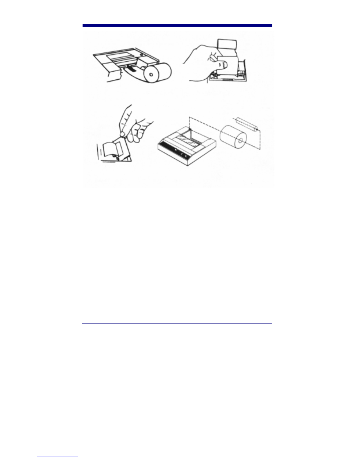
Figure 10-5. Replacing the QCP or QCHSP paper roll
Remove ribbon cartridge from the QCP or QCHSP
1. Press the printer power switch to the Off (down left) position.
2. Remove the printer cover by locating the four small grooves embossed on
each side of the printer cover and tilting the cover open by pushing down
gently on both sets of these grooves. The ribbon cartridge should be visible.
3. Push down on the right side of the ribbon cartridge (marked PUSH) and
remove the cartridge from the printer compartment.
4. Slide the paper through the gap between the inked ribbon and the frame of
the new ribbon cartridge.
5. Set the new cartridge into the printer compartment and press both sides to
secure it in place. The cartridge must be properly seated and aligned for the
best print quality. If you get ribbon ink on the printer’s plastic case, wipe it off
immediately. Once the ink dries it is difficult to remove.
6. Replace the printer cover by pushing the back of it down into place and
pressing the front down to lock it in place.
49
Page 56

7. Turn the cartridge ribbon advance knob (marked by an arrow on the
cartridge) clockwise to remove slack from the ribbon.
8. Replace the printer cover.
Connect the QCP or QCHSP to the Quick Check
1. Press the printer power switch to the Off (down left) position.
2. Plug the transformer into an outlet.
3. Plug the interface cable into the socket on the side of the Quick Check.
4. Connect the 12-pin connector of the interface cable into the rear of the
printer. Secure the connector by tightening the screws on each side of the
connector.
Press the power switch to the On (center) position. The red LED lights and a
Ready message appear which indicates the printer’s build-in microprocessor has
verified its internal operation prints.
Perform a QCP or QCHSP self-test:
The self-test tests the print head and ribbon.
1. Ensure the power switch is in the Off (down left) position and there is paper
in the printer.
2. Plug the power source into the printer.
3. Press and hold the power switch in the Paper Feed (down right) position
until the LED lights and the printer starts to operate.
4. Release the power switch, The printer performs the self-test and prints its full
set of character.
Troubleshooting the QCP or QCHSP
Having the incorrect printer interface configuration setting for the type of printer
you are using may cause printing difficulties. Set the QCP to Std and the QCHSP
to HSP.
If you use the printer infrequently, the print impression sometimes becomes weak
because the ribbon dries out. If the printed material is difficult to read and you
suspect this is the cause of the problem, advance to a properly inked portion of
the ribbon by pressing the power switch into the Paper Feed position.
The QCSSP is shown in Figure 10-6.
50
Page 57

Figure 10-6. QCSSP
The power switch is located on the printer’s rear panel. It toggles between on and
off. A red light-emitting diode (LED) to the front of the printer indicates the on and
off status. If this light is lit, the printer is turned on. If this light is not lit, the printer
is turned off. If this light flashes, a printer error exists. Refer to Troubleshooting
later in this section for a list of the possible errors.
The Paper Feed button on the front panel has two functions. It feeds paper into
the printer and is used for the printer self-test. The Paper Empty LED lights when
the paper roll is empty.
The printer head lever is located on the front of the printer. This lever raises and
lowers the printer head. You will need to raise the printer head to load paper.
When this lever is raised, the Power LED flashes and the printer will not operate.
You will need to lower the printer head to use the printer.
A panel of DIPswitches is located on the rear of the printer. These switches are
set at the factory for proper operation with the Quick Check.
An interface cable connects the printer directly to the Quick Check to provide
easy exchange of scanning results. The connectors on each end of the cable are
keyed so that they cannot be plugged in the wrong way.
Hand Held Products recommends you use the thermal paper they supply for
correct operation of the QCSSP. The order number is QCTP. Contact Hand Held
Products Customer Administration at the numbers listed on the front cover of the
manual.
51
Page 58

Turn on and off the QCSSP
1. To turn on the printer, press the power switch to the On position. The Power
LED lights.
2. To turn off the printer, press the power switch to the Off position. The Power
LED turns off.
After you turn off the printer, wait at least three seconds to turn on the power for
the proper initialization procedure.
Setup the QCSSP
1. Place the printer on a hard, flat surface such as a table or desktop.
2. Press the power switch into the Off position.
3. Plug the power cable into the printer
4. Plug the other end of the power cable into a wall outlet.
Install or replace the QCSSP paper roll:
1. Press the printer power switch to the Off position.
2. Lift the paper roll cover.
3. Raise the print head by moving the printer head lever toward you until it
stops.
4. If necessary, remove the empty roll. If there is any paper on the roll, gently
pull it out the front of the printer.
Warning: Do not pull paper out of the back of the printer, as this will damage the
mechanism.
5. Unroll several inches of paper from a new roll and cut a straight edge on the
paper if it is jagged or wrinkled. A straight edge helps guide the paper into
the printer.
6. Hold the paper roll so the paper will feed from the bottom of the roll into the
printer and place the roll in the paper trough.
7. Using your fingers feed the end of the paper into the space below the round
platen.
8. Lower the printer head by moving the printer head lever away from you until
it stops.
9. Press Paper Feed to feed the paper until it extends out of the top about an
inch.
10. Close the paper cover. Be sure the paper is above the lid.
52
Page 59

Perform a QCSSP self-test
The self-test tests the print head.
1. Ensure the power switch is in the Off position and there is paper in the
printer.
2. Plug the power source into the printer.
3. Press and hold down Paper Feed while you press the power switch on. The
printer begins to print the self-test. The printer will continue printing the selftest until you stop it. You can stop printing by pressing Paper Feed.
The first line printed is the printer identification line.
The second line tells you the type of communications interface that the printer is
using (SERIAL) and the baud rate setting (VHS).
With serial communication set, the third line tells you the handshake mode with
which the printer is working. The standard handshake for RS232 communications
is the BUSY handshake setting.
The fourth line tells you the amount of RAM (Random Access Memory) buffer
installed in the printer. The QCSSP is shipped with a 1K (kilobyte) buffer.
Troubleshooting the QCSSP
Printing difficulties may be caused by:
• the wrong printer interface configuration option for the type of printer you
are using. The QCSSP should be set to VHS.
• the wrong communications interface. The QCSSP should use the serial
communications interface. If this is incorrect, you should contact Hand
Held Products.
Table 10-1 lists the types of problems that might occur during QCSSP operation
and gives you information about resolving the error.
53
Page 60

Table 10-1. QCSSP troubleshooting chart
Indication
Printing slowed power
Cause/Corrective Action
May be high temperature, when
unit cools printing resumes at
LED flashes
standard speed
Printing stopped May be loss of power, check
supply. Data will be lost.
Printing stopped and Paper
Empty LED on
Printing stopped and Power
LED flashes
Replace paper. Be sure to lower
print head
1. If print head is raised, lower
it.
2. May be an overvoltage or
undervoltage, check line,
wait for voltage to return to
acceptable level.
3. May be high temperature,
when unit cools, printing
resumes at standard speed.
54
Page 61

Indication
Printing special characters while
using RS-232 connection
“?” is framing error
Cause/Corrective Action
May be interface connection
error.
1. Check connections; ensure
serial communications is
“@” is overrun error
selected.
2. Check cable integrity.
3. Check baud rate (VHS) with
QC
Paper Jam Remove jammed paper
Non Power Surge
55
Page 62

.
56
Page 63

11. Customer Support
Obtaining Factory Service
Hand Held Products provides service for all its products through service centers
throughout the world. To obtain warranty or non-warranty service, return the unit
to Hand Held Products (postage paid) with a copy of the dated purchase record
attached. Contact the appropriate location below to obtain a Return Material
Authorization number (RMA #) before returning the product.
North America
Hand Held Products Corporate Offices
Telephone: (800) 782-4263, Option 3
Fax: (704) 566-6015
E-mail: naservice@handheld.com
America Latina
Hand Held Products America Latina
Teléfono: (239) 263-7600
Fax: (239) 263-9689
E-mail: laservice@handheld.com
Brazil
Hand Held Products Brazil
Telephone: +55 (21) 2176-0250
Fax: +55 (21) 2176-0249
E-mail: suporte@handheld.com
Europe, Middle East, and Africa
Hand Held Products Europe
Telephone: + 31 (0) 40 29 01 633
Fax: + 31 (0) 40 2901631
E-mail: euservice@handheld.com
Asia Pacific
Hand Held Products Asia/Pacific
Telephone: + 852-2511-3050
Fax: +852-2511-3557
E-mail: apservice@handheld.com
57
Page 64

Japan
Hand Held Products Japan
Telephone: +81-3-5770-6312
Fax: +81-3-5770-6313
E-mail: apservice@handheld.com
Online Product Service and Repair Assistance
You can also access product service and repair assistance online at
www.handheld.com
.
Technical Assistance
If you need assistance installing or troubleshooting your scanner, please call your
Distributor or the nearest Hand Held Products technical support office:
North America/Canada:
Telephone: (800) 782-4263, option 4 (8 a.m. to 6 p.m. EST)
Fax: (315) 685-4960
E-mail: natechsupport@handheld.com
America Latina:
Teléfono: (704) 998-3998, opción 8
E-mail: latechsupport@handheld.com
Brazil
Telephone: +55 (21) 2176-0250
Fax: +55 (21) 2176-0249
E-mail: suporte@handheld.com
Europe, Middle East, and Africa:
TelephoneEuropean Ofc: Int+31 (0) 40 79 99 393
U.K. Ofc: Int+44 1925 240055
E-mail: eutechsupport@handheld.com
Asia Pacific:
Telephone: Int+852-3188-3485 or 2511-3050
E-mail: aptechsupport@handheld.com
58
Page 65

Online Technical Assistance
You can also access technical assistance online at www.handheld.com.
Limited Warranty
Hand Held Products, Inc., ("Hand Held Products") warrants its products to be
free from defects in materials and workmanship and to conform to Hand Held
Products' published specifications applicable to the products purchased at the
time of shipment. This warranty does not cover any Hand Held Products product
which is (i) improperly installed or used; (ii) damaged by accident or negligence,
including failure to follow the proper maintenance, service, and cleaning
schedule; or (iii) damaged as a result of (A) modification or alteration by the
purchaser or other party, (B) excessive voltage or current supplied to or drawn
from the interface connections, (C) static electricity or electro-static discharge,
(D) operation under conditions beyond the specified operating parameters, or (E)
repair or service of the product by anyone other than Hand Held Products or its
authorized representatives.
This warranty shall extend from the time of shipment for the duration published
by Hand Held Products for the product at the time of purchase ("Warranty
Period"). Any defective product must be returned (at purchaser’s expense)
during the Warranty Period to Hand Held Products' factory or authorized service
center for inspection. No product will be accepted by Hand Held Products
without a Return Materials Authorization, which may be obtained by contacting
Hand Held Products. In the event that the product is returned to Hand Held
Products or its authorized service center within the Warranty Period and Hand
Held Products determines to its satisfaction that the product is defective due to
defects in materials or workmanship, Hand Held Products, at its sole option, will
either repair or replace the product without charge, except for return shipping to
Hand Held Products.
EXCEPT AS MAY BE OTHERWISE PROVIDED BY APPLICABLE LAW, THE
FOREGOING WARRANTY IS IN LIEU OF ALL OTHER COVENANTS OR
WARRANTIES, EITHER EXPRESSED OR IMPLIED, ORAL OR WRITTEN,
INCLUDING, WITHOUT LIMITATION, ANY IMPLIED WARRANTIES OF
MERCHANTABILITY OR FITNESS FOR A PARTICULAR PURPOSE.
HAND HELD PRODUCTS’ RESPONSIBILITY AND PURCHASER’S
EXCLUSIVE REMEDY UNDER THIS WARRANTY IS LIMITED TO THE REPAIR
OR REPLACEMENT OF THE DEFECTIVE PRODUCT. IN NO EVENT SHALL
HAND HELD PRODUCTS BE LIABLE FOR INDIRECT, INCIDENTAL, OR
CONSEQUENTIAL DAMAGES, AND, IN NO EVENT, SHALL ANY LIABILITY
OF HAND HELD PRODUCTS ARISING IN CONNECTION WITH ANY
PRODUCT SOLD HEREUNDER (WHETHER SUCH LIABILITY ARISES FROM
A CLAIM BASED ON CONTRACT, WARRANTY, TORT, OR OTHERWISE)
59
Page 66

EXCEED THE ACTUAL AMOUNT PAID TO HAND HELD PRODUCTS FOR
THE PRODUCT. THESE LIMITATIONS ON LIABILITY SHALL REMAIN IN
FULL FORCE AND EFFECT EVEN WHEN HAND HELD PRODUCTS MAY
HAVE BEEN ADVISED OF THE POSSIBILITY OF SUCH INJURIES, LOSSES,
OR DAMAGES. SOME STATES, PROVINCES, OR COUNTRIES DO NOT
ALLOW THE EXCLUSION OR LIMITATIONS OF INCIDENTAL OR
CONSEQUENTIAL DAMAGES, SO THE ABOVE LIMITATION OR EXCLUSION
MAY NOT APPLY TO YOU.
All provisions of this Limited Warranty are separate and severable, which means
that if any provision is held invalid and unenforceable, such determination shall
not affect the validity of enforceability of the other provisions hereof. Use of any
peripherals not manufactured/sold by Hand Held Products voids the warranty.
This includes but is not limited to: cables, power supplies, cradles, and docking
stations. Hand Held Products, Inc. extends these warranties only to the first endusers of the products. These warranties are nontransferable.
The limited duration of the warranty for the Quick Check 200 Series is for two (2)
years.
60
Page 67

61
Page 68

Page 69

Page 70

Page 71

Page 72

Hand Held Products, Inc.
700 Visions Drive
P.O. Box 208
Skaneateles Falls, NY 13153-0208
QC200-UG Rev C
7/05
 Loading...