

Page 1
IT3800/3900
Handheld Linear Imager
™
User’s Guide
Page 2

Disclaimer
Hand Held Products, Inc. (“Hand Held Products”) reserves the right to make
changes in specifications and other information contained in this document
without prior notice, and the reader should in all cases consult Hand Held
Products to determine whether any such changes have been made. The
information in this publication does not represent a commitment on the part of
Hand Held Products.
Hand Held Products shall not be liable for technical or editorial errors or
omissions contained herein; nor for incidental or consequential damages
resulting from the furnishing, performance, or use of this material.
This document contains proprietary information that is protected by copyright. All
rights are reserved. No part of this document may be photocopied, reproduced,
or translated into another language without the prior written consent of Hand
Held Products.
© 2000-2005 Hand Held Products, Inc. All rights reserved.
Web Address: www.handheld.com
Page 3

Statement of Agency Compliance
This device complies with part 15 of the FCC Rules. Operation is subject to the
following two conditions: (1) this device may not cause harmful interference, and
(2) this device must accept any interference received, including interference that
may cause undesired operation.
FCC Class B Compliance Statement
This equipment has been tested and found to comply with the limits for a Class
B digital device pursuant to part 15 of the FCC Rules. These limits are designed
to provide reasonable protection against harmful interference in a residential
installation. This equipment generates, uses, and can radiate radio frequency
energy and, if not installed and used in accordance with the instructions, may
cause harmful interference to radio communications. However, there is no
guarantee that interference will not occur in a particular installation. If this
equipment does cause harmful interference to radio or television reception,
which can be determined by turning the equipment off and on, the user is
encouraged to try to correct the interference by one or more of the following
measures:
• Reorient or relocate the receiving antenna.
• Increase the separation between the equipment and receiver.
• Connect the equipment into an outlet on a circuit different from that to which
the receiver is connected.
• Consult the dealer or an experienced radio or television technician for help.
Caution: Any changes or modifications made to this device that are not
expressly approved by Hand Held Products, Inc. may void the user’s authority
to operate the equipment.
Note: To maintain compliance with FCC Rules and Regulations, cables
connected to this device must be shielded cables, in which the cable shield
wire(s) have been grounded (tied) to the connector shell.
Canadian Notice
This equipment does not exceed the Class B limits for radio noise emissions as
described in the Radio Interference Regulations of the Canadian Department of
Communications.
Le present appareil numerique n’emet pas de bruits radioelectriques depassant
les limites applicables aux appareils numeriques de la classe B prescrites dans
le Reglement sur le brouillage radioelectrique edicte par le ministere des
Communications du Canada.
Page 4

The CE mark on the product indicates that the system has been
tested to and conforms with the provisions noted within the 89/336/
EEC Electromagnetic Compatibility Directive and the 73/23/EEC
Low Voltage Directive.
For further information please contact:
Hand Held Products, Inc.
Nijverheidsweg 9
5627 BT Eindhoven
The Netherlands
Hand Held Products shall not be liable for use of our product with equipment
(i.e., power supplies, personal computers, etc.) that is not CE marked and does
not comply with the Low Voltage Directive.
UL and cUL Statement
UL listed UL1950 and CSA 22.2 No.950. cUL listed UL1950 and CSA 22.2 No
950.
LED Safety Statement
This device has been tested in accordance with EN60825-1 LED safety, and has
been certified to be under the limits of a Class 1 LED device.
TÜV Statement
TÜV or GS marked to EN60950 and EN60825-1.
C-TIC Statement
Conforms to AS/NZS 3548. C-Tick number: N10410.
Patents
Please refer to the IT3800/3900 packaging for patent information.
Page 5

Table of Contents
Chapter 1 - Getting Started
Typical Applications for the IT3900 .................................... 1-1
About This Manual............................................................... 1-1
Unpacking the Scanner......................................................... 1-2
IT3800 Scanner Identification.............................................. 1-3
IT3900 Scanner Identification.............................................. 1-3
Connecting the Scanner When Powered by Host
(Keyboard Wedge) ............................................................ 1-4
Mounting Information for the IT3900 ................................. 1-5
Specular Zone................................................................. 1-6
Plug and Play........................................................................ 1-6
IBM 4683 Ports 5B, 9B, and 17 Interface............................ 1-8
USB Interface ....................................................................... 1-9
USB Converter.................................................................... 1-11
OCIA Interface ................................................................... 1-11
NCR OCIA Short Format (8 Bit) Interface ........................ 1-12
NCR OCIA Long Format (9 Bit) Interface......................... 1-12
Nixdorf OCIA Interface...................................................... 1-13
Serial Wedge....................................................................... 1-13
Chapter 2 - Terminal Interfaces
Keyboard Wedge Connection............................................... 2-1
Terminal ID ......................................................................... 2-2
Supported Terminals............................................................. 2-3
Keyboard Country ................................................................ 2-5
Keyboard Style ..................................................................... 2-5
Keyboard Modifiers.............................................................. 2-6
i
Page 6

Serial Port Connection.......................................................... 2-8
Baud Rate....................................................................... 2-9
RS-232 Word Length: Data Bits, Stop Bits, and Parity2-10
RS-232 Handshaking ................................................... 2-12
Wand Emulation Connection....................................... 2-12
Wand Emulation Transmission Rate............................ 2-13
Wand Emulation Polarity............................................. 2-14
Wand Emulation Idle ................................................... 2-14
PDF417 Wand Emulation................................................... 2-15
Data Block Size............................................................ 2-15
Delay Between Blocks................................................. 2-15
Overall Checksum........................................................ 2-16
Chapter 3 - Output
Scan Rate.............................................................................. 3-1
Beeper Volume..................................................................... 3-1
Beeper Tone.......................................................................... 3-2
Scan Voting .......................................................................... 3-2
Reduce Quiet Zone............................................................... 3-2
Reread Delay ........................................................................ 3-3
Good Read Delay.................................................................. 3-4
Trigger Mode........................................................................ 3-4
Chapter 4 - Data Editing
Prefix/Suffix Overview......................................................... 4-1
To Add a Prefix or Suffix: ............................................. 4-1
To Clear One or All Prefixes or Suffixes:...................... 4-2
To Add a Carriage Return Suffix to all Symbologies.... 4-3
Prefix Selections............................................................. 4-4
Suffix Selections ............................................................ 4-4
Symbology Chart.................................................................. 4-5
ASCII Conversion Chart (Code Page 1252)......................... 4-6
Function Code Transmit................................................. 4-8
ii
Page 7

Intercharacter, Interfunction, and Intermessage Delays ....... 4-8
Intercharacter Delay .......................................................4-8
User Specified Intercharacter Delay...............................4-9
Interfunction Delay.......................................................4-10
Intermessage Delay ......................................................4-10
Chapter 5 - Data Formatting
Data Format Editor Introduction........................................... 5-1
To Add a Data Format....................................................5-1
Other Programming Selections ...................................... 5-2
Data Format Editor Commands...................................... 5-2
Data Format Editor......................................................... 5-4
Data Formatter................................................................ 5-5
Alternate Data Formats .................................................. 5-5
Chapter 6 - Secondary Interface
Secondary Code 39 Wand Emulation...................................6-1
Secondary RS-232 Connection.............................................6-1
Secondary Non Decoded Output Laser Emulation............... 6-2
Non Decoded Output Laser Emulation Transmission Rate.. 6-2
Non Decoded Output Laser Emulation Polarity................... 6-2
Non Decoded Laser Emulation Idle...................................... 6-3
Disabling the Secondary Interface........................................6-3
Secondary Trigger Mode ......................................................6-3
Chapter 7 - Symbologies
Introduction...........................................................................7-1
All Symbologies....................................................................7-1
Message Length Description ................................................7-2
Codabar.................................................................................7-3
Start/Stop Characters ..................................................... 7-3
Check Character .............................................................7-4
Concatenation................................................................. 7-5
Codabar Message Length............................................... 7-5
iii
Page 8

Code 39................................................................................. 7-6
Start/Stop Characters..................................................... 7-6
Check Character............................................................. 7-7
Code 39 Message Length............................................... 7-7
Code 39 Append............................................................. 7-8
Base 32........................................................................... 7-8
Full ASCII...................................................................... 7-9
Interleaved 2 of 5................................................................ 7-10
Check Digit .................................................................. 7-10
Interleaved 2 of 5 Message Length.............................. 7-11
Strict Decoding............................................................. 7-11
Code 93............................................................................... 7-12
Code 93 Message Length............................................. 7-12
Code 2 of 5.......................................................................... 7-13
Code 2 of 5 Message Length........................................ 7-13
IATA Code 2 of 5............................................................... 7-14
IATA Code 2 of 5 Message Length............................. 7-14
Matrix 2 of 5....................................................................... 7-15
Matrix 2 of 5 Message Length..................................... 7-15
Code 11............................................................................... 7-16
Check Digits Required................................................. 7-16
Code 11 Message Length............................................. 7-17
Code 128............................................................................. 7-18
<GS> Substitution........................................................ 7-18
Code 128 Message Length 19
Telepen .............................................................................. 7-20
Telepen Output............................................................. 7-20
Telepen Message Length.............................................. 7-20
UPC A................................................................................. 7-21
Check Digit .................................................................. 7-21
Number System............................................................ 7-21
UPC A, continued ........................................................ 7-22
Addenda ....................................................................... 7-22
Addenda Required........................................................ 7-22
Addenda Separator....................................................... 7-23
UPC Strict Decoding.................................................... 7-23
iv
Page 9

UPC E0 and UPC E1 ..........................................................7-24
UPC E Expand..............................................................7-24
Check Digit...................................................................7-25
Number System............................................................ 7-25
Addenda........................................................................7-26
Addenda Required........................................................ 7-26
Addenda Separator .......................................................7-27
EAN/JAN 13....................................................................... 7-28
Check Digit...................................................................7-28
Addenda........................................................................7-29
Addenda Required........................................................ 7-29
Addenda Separator .......................................................7-30
ISBN Enable.................................................................7-30
EAN/JAN 8......................................................................... 7-31
Check Digit...................................................................7-31
Addenda........................................................................7-32
Addenda Required........................................................ 7-32
Addenda Separator .......................................................7-33
MSI ..................................................................................... 7-34
MSI, continued............................................................. 7-34
Check Character ...........................................................7-34
MSI Message Length....................................................7-35
Plessey.................................................................................7-36
Plessey Message Length............................................... 7-36
RSS-14................................................................................ 7-37
RSS Limited........................................................................7-37
RSS Expanded .................................................................... 7-38
RSS Expanded Message Length...................................7-38
China Post Code.................................................................. 7-39
China Post Message Length.........................................7-39
PDF417...............................................................................7-40
PDF417 Message Length .............................................7-40
Show GLI Blocks........................................................ 7-41
Scan Diagnostics ..........................................................7-41
PDF Learn Mode..........................................................7-42
v
Page 10

MicroPDF417 .................................................................... 7-43
MicroPDF417............................................................... 7-43
MicroPDF417 Message Length ................................... 7-43
EAN•UCC Composite Symbology .................................... 7-44
EAN•UCC Composite........................................................ 7-44
Enable UPC/EAN Version ................................................. 7-44
EAN•UCC Composite Code Message Length............. 7-45
Chapter 8 - Cloning
Procedure.............................................................................. 8-1
Chapter 9 - Visual Menu
Visual Menu Introduction..................................................... 9-1
Temporary Visual Menu Configuration......................... 9-1
Installing Visual Menu from the Web............................ 9-1
Upgrading USB Firmware ............................................. 9-2
Chapter 10 - Interface Keys
Keyboard Function Relationships....................................... 10-1
Supported Interface Keys .................................................. 10-3
Chapter 11 - Utilities
To Add a Test Code I.D. Prefix to All Symbologies.......... 11-1
Show Software Revision..................................................... 11-1
Show Data Format.............................................................. 11-1
Specular Effect Reduction.................................................. 11-2
Chapter 12 - Serial Programming Commands
Conventions........................................................................ 12-1
Menu Command Syntax..................................................... 12-1
Query Commands......................................................... 12-2
Concatenation of Multiple Commands ........................ 12-2
Trigger Commands............................................................. 12-4
Resetting the Factory Settings............................................ 12-4
vi
Page 11

Menu Commands ...............................................................12-5
PDF417 Wand Emulation ............................................ 12-7
Chapter 13 - Product Specifications
IT3800 Product Specifications............................................ 13-1
IT3900 Product Specifications............................................ 13-2
Standard Cable Pinouts.......................................................13-3
Chapter 14 - Maintenance
Repairs ................................................................................14-1
Maintenance........................................................................ 14-1
Replacing the Interface Cable ......................................14-2
Troubleshooting.................................................................. 14-2
Chapter 15 - Customer Support
Product Service and Repair................................................. 15-1
Online Product Service and Repair Assistance............ 15-2
Technical Assistance........................................................... 15-2
Online Technical Assistance ........................................15-2
Limited Warranty ...............................................................15-3
vii
Page 12

viii
Page 13
1
Getting Started
The IT3800 is a high performance linear imaging scanner from Hand Held
Products. The IT3800 marks a new performance level for handheld scanners.
Linear imaging technology is defined by a bright and sharply focused aiming line,
high resolution imaging, and fast reading speed. The IT3800 is comfortable to
hold, easy to use, rugged, and excellent for all general scanning applications.
The IT3900 is a fixed mount bar code scanner designed for retail kiosks,
manufacturing WIP tracking, document processing, or other OEM applications.
It is a complete decoded output scanner that is easy to integrate. It
communicates with PCs or host terminals via keyboard wedge or a serial RS-232
interface. The IT3900 can be used internally or externally. The housing provides
protection from dust, dirt, and electrostatic discharge.
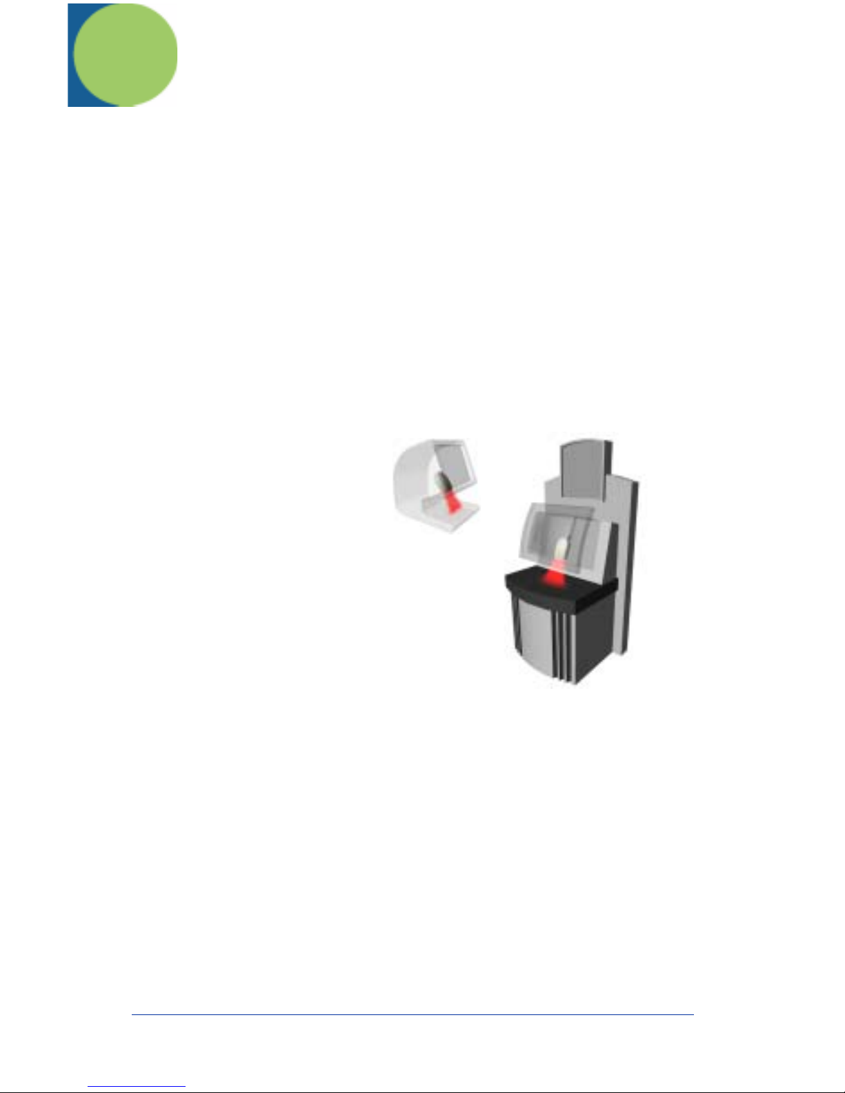
Typical Applications for the IT3900
The IT3900 is an ideal scanner
for retail kiosks. The bright
aiming line and large working
range make scanning easy for
untrained users.
The IT3900 mounted in a stand
makes an efficient bar code
document reader; it takes up a
minimum of counter space and
reads and transmits data
quickly.
About This Manual
This User’s Guide provides installation and programming instructions for the
IT3800/3900. Product specifications, dimensions, warranty, and customer
support information are also included.
Hand Held Products bar code scanners are factory programmed for the most
common terminal and communications settings. If you need to change these
settings, programming is accomplished by scanning the bar codes in this guide.
An asterisk (*) next to an option indicates the default setting.
IT3800/3900 User’s Guide 1 - 1
Page 14
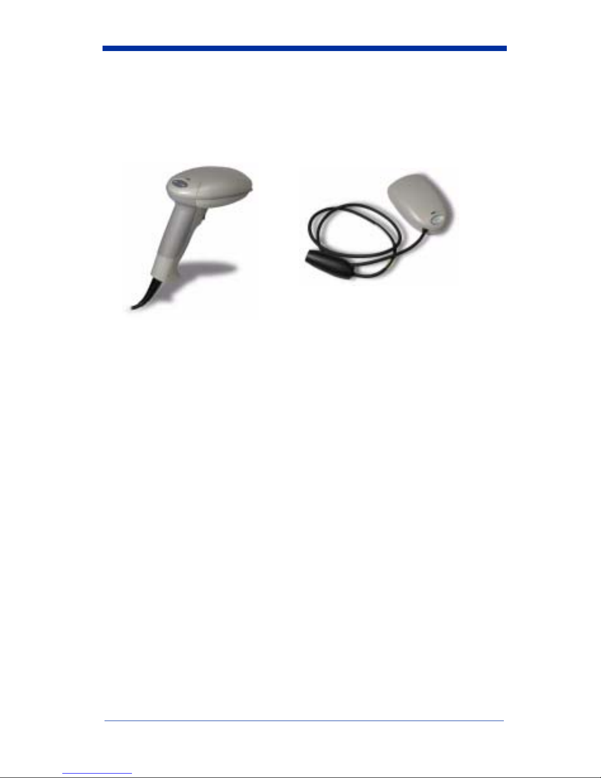
Unpacking the Scanner
Open the carton. The shipping carton or container should contain:
An IT3800:
• Check to make sure everything you ordered is present.
• Save the shipping container for later storage or shipping.
• Check for damage during shipment. Report damage immediately to the
carrier who delivered the carton.
or an IT3900:
1 - 2 IT3800/3900 User’s Guide
Page 15
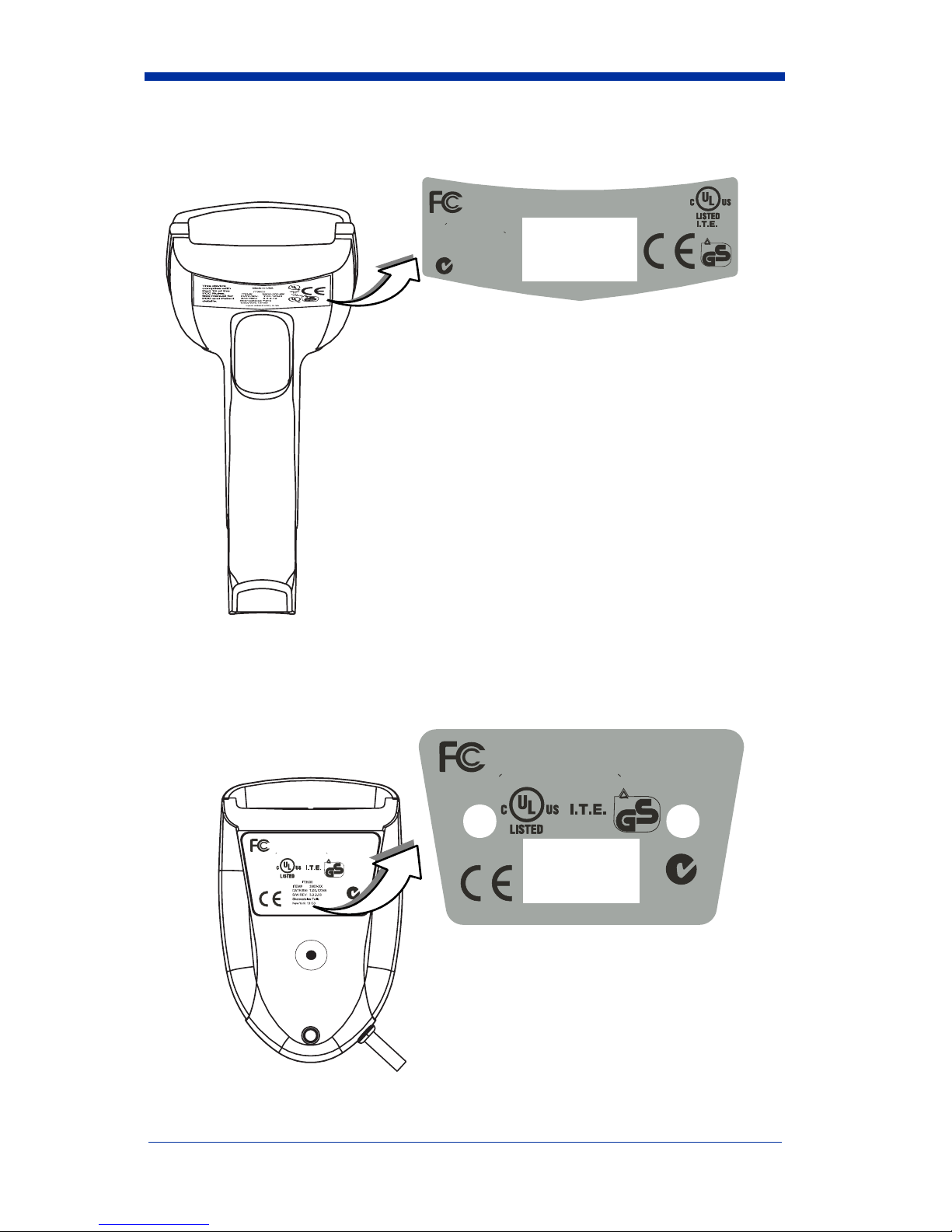
IT3800 Scanner Identification
Tes te d to C omp ly W ith FC C S ta nda rds
This Class B digital apparatus complies with Canadian
ICES-003. Cet appareil
numerique de la
Classe B est conforme a la
norme NMB-003 du Canada.
FOR HOME OR OFFICE USE
N10410
Seemanualfor
Patentdetails.
Hand Held Products, Inc.
www.handheld.com
E153740
Input:
4.5-5.5VDC,
0-.3A
Made in USA
7D21
.
TUV
Rheinland
ProductSafety
...
geprufte
Sicherheit
IT3900 Scanner Identification
IT3900 Scanner
Bottom View
Cet appareil numerique de la Classe B est conforme a la norme NMB-003 du Canada.
E 153740
FOR HOME OR OFFICE USE
Tested toComplyWithFCC Standards
This Class B digital apparatus complies with Canadian ICES-003.
Cet appareil numerique de la Classe B est conforme a la norme NMB-003 du Canada.
E153740
Seemanual for
Patentdetails.
Hand Held Products, Inc.
7D21
.
TUV
Rheinland
Product Safety
...
geprufte
Sicherheit
Made in USA
www.handheld.com
Input:
4.5-5.5VDC, 0-.3A
N10410
Seemanualfor
Pa tent de tails .
FOR HOME OR OFFICE USE
Tes ted to C om ply W ith F C C S tand ar ds
This Class B digital apparatus complies with Canadian ICES-003.
Made in USA
.
www.handheld.com
TUV
Rheinland
Product Safety
...
7D21
geprufte
Sicherheit
Input:
4.5-5.5 VDC, 0-.3A
N10410
Hand Held Products, Inc.
IT3800/3900 User’s Guide 1 - 3
Page 16
Connecting the Scanner When Powered by Host
Disconnect
(Keyboard Wedge)
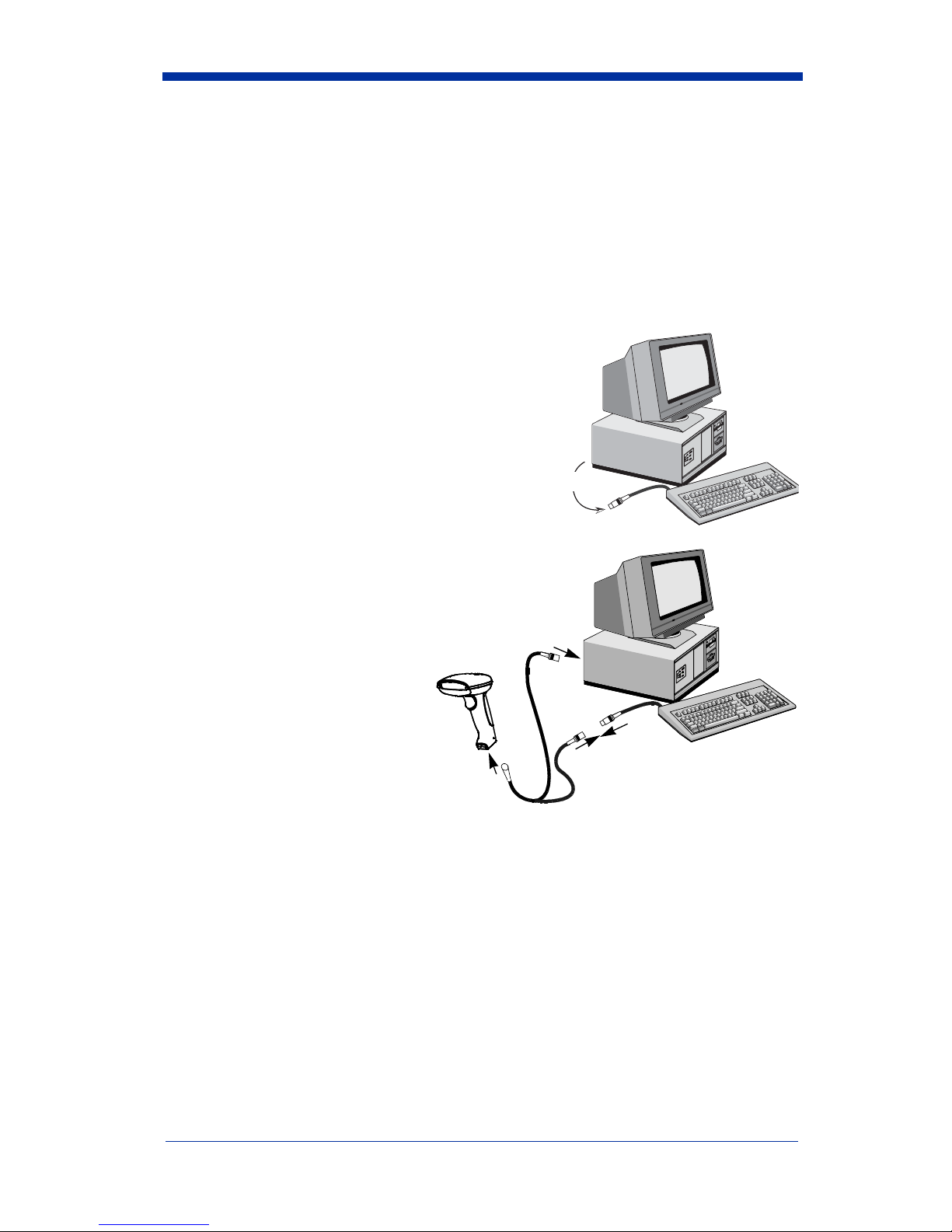
A scanner can be connected between the keyboard and PC as a “keyboard
wedge,” plugged into the serial port, or connected to a portable data terminal in
wand emulation or non decoded output mode. The following is an example of a
keyboard wedge connection:
1. Turn off power to the terminal/computer.
2. Disconnect the keyboard cable from the
back of the terminal/computer.
Disconnect
3. Connect the appropriate
interface cable to the
scanner and to the terminal/
computer.
3
1
4. Turn the terminal/computer
power back on. The scanner will beep twice.
5. Verify the scanner operation by scanning a bar code from the back cover of
this manual. The scanner will beep once.
2
1 - 4 IT3800/3900 User’s Guide
Page 17
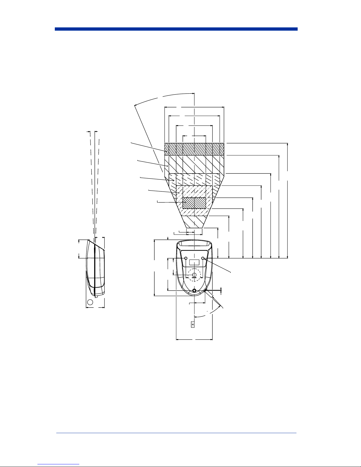
Mounting Information for the IT3900
23˚ typ
4.9
4.2
3
2˚ Ref typ
1.52
Aperture plane
15 mil
13 mil
7.5 mil
5 mil
3 mil
Optical center is ± 2" from horizontal.
(Angle begins at aperture plane.)
.8
1.52 Ref
4.64
2.67
B
1.52
1.9
9.5
8.5
7
6
5
.65
1.3
2.5
(13 mil and 15 mil)
.700
.700
.04
.89
47.5˚
4.1
3.5
(5 mil and 7.5 mil)
M4 Inserts typ 3
Thread depth
4.7 mm (.185")
TYPICAL PERFORMANCE ON HIGH QUALITY SYMBOLS.
Note: Measurements are in inches.
IT3800/3900 User’s Guide 1 - 5
Cable Exit
2.99
Page 18
Mounting Information, continued
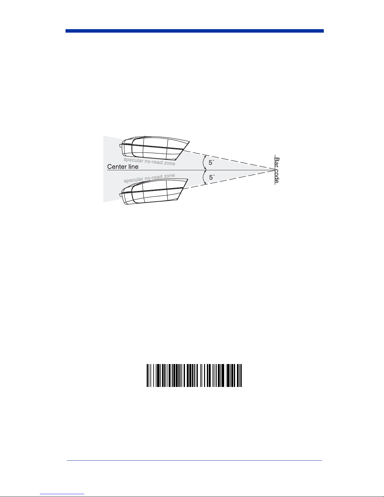
Specular Zone
The IT3900 must be mounted at a 5 degree, or greater, angle to the bar code in
order to scan properly:
The scanner is now connected and ready to communicate with your terminal/PC.
You must program the scanner for your interface before bar code data can be
transmitted to your terminal/PC. If you are using the scanner as a keyboard
wedge, turn to page 2-1. If the scanner is connected via a serial port, turn to
page 2-8. If this is a wand emulation application, turn to page 2-15, and for a non
decoded output connection, turn to page 6-2.
Plug and Play
Plug and Play bar codes provide instant scanner set up for commonly used
interfaces.
Note: After you scan one of the codes, power cycle the host terminal to have the
interface in effect.
The most common interface is Keyboard Wedge. The following Keyboard
Wedge bar code also programs a carriage return (CR) suffix.
Keyboard Wedge Interface for IBM PC AT and
Compatibles
1 - 6 IT3800/3900 User’s Guide
Page 19

The following Plug and Play bar code for IBM XT and Compatibles also
programs a carriage return (CR) suffix.
IBM XT and Compatibles
The following Plug and Play bar code for IBM PS-2 and Compatibles also
programs a carriage return (CR) suffix.
IBM PS-2 and Compatibles
Use Non Decoded Output Laser Emulation when connecting to a secondary
terminal with integral decoding. This also sets the transmission rate to 36 scans
per second and the polarity to white high.
Non Decoded Output
Laser Emulation
For most laptops, scanning the Laptop Direct Connect bar code allows
operation of the integral keyboard. The following Laptop Direct Connect bar
code also programs a carriage return (CR) suffix.
Laptop Direct Connect
The RS-232 Interface bar code is used when connecting to the serial port of a
PC or terminal. The following RS-232 Interface bar code adds a suffix of a CR
and LF, and also programs the parameters:
Option
Setting
Baud Rate 9600 bps
Parity Even
IT3800/3900 User’s Guide 1 - 7
Page 20

Option
Setting
Data Format 7 data bits, parity bit, 1 stop bit (8 bit data)
RS-232 Interface
In Wand Emulation mode, the scanner decodes the bar code then sends data in
the same format as a wand scanner. The Same Code format transmits UPC,
EAN, Code 128 and Interleaved 2 of 5 bar codes without any changes, but
converts all other symbologies to Code 39.
Wand Emulation Same Code
The following Wand Emulation bar code sets the interface to Wand Emulation
mode and translates bar code data as Code 39 symbology. It also programs the
Transmission Rate to 25 inches per second, and Output Polarity to black high.
Wand Emulation (Code 39 Format)
Note: For the 3800PDF model: When the 3800PDF interface is set to wand
emulation, all PDF417 bar code data is transmitted as Code 128. Data
from other symbologies follow the rules described above.
IBM 4683 Ports 5B, 9B, and 17 Interface
Note: The following Retail “Plug and Play” codes are for use with the 3800LR-
11 and 3800LR-15 models only.
Scan one of the following “Plug and Play” codes to program the IT3800 for IBM
4683 Port 5B, 9B, or 17.
1 - 8 IT3800/3900 User’s Guide
Page 21

Note: After scanning one of these codes, you must re-boot the cash register.
IBM 4683 Port 5B Interface
(Default for -11 Models)
IBM 4683 Port 9B HHBCR-1 Interface
IBM 4683 Port 9B HHBCR-2 Interface
IBM 4683 Port 17 Interface
Each bar code above also programs the following suffixes for each symbology:
Symbology
Suffix
EAN 8 0C
EAN 13 16
UPC A 0D
UPC E 0A
Code 39 00 0A 0B
Interleaved 2 of 5 00 0D 0B
Code 128 00 18 0B
USB Interface
Note: The following USB “Plug and Play” codes (IBM SurePOS handheld and
tabletop scanners) are for use with the 3800LX-15 model only.
Scan one of the following “Plug and Play” codes to program the IT3800 for IBM
SurePos (USB Handheld scanner) or IBM SurePos (USB Tabletop scanner).
IT3800/3900 User’s Guide 1 - 9
Page 22

Note: After scanning one of these codes, you must re-boot the cash register.
IBM SurePos (USB Handheld Scanner) Interface
IBM SurePos (USB Tabletop Scanner) Interface
Each bar code above also programs the following suffixes for each symbology:
Symbology
Suffix
EAN 8 0C
EAN 13 16
UPC A 0D
UPC E 0A
Code 39 00 0A 0B
Interleaved 2 of 5 00 0D 0B
Code 128 00 18 0B
Scan one of the following codes to program the IT3800 for USB PC Keyboard or
USB Macintosh Keyboard. Default = USB Keyboard (PC).
* USB Keyboard (PC)
USB Keyboard (Mac)
Scan the following code to program the IT3800 for USB HID bar code scanners.
1 - 10 IT3800/3900 User’s Guide
USB HID Bar Code Scanner
Page 23

USB Converter
Note: The USB converter is for use with the 3800-11 and 3800/3900-12 models
only.
The IT3800-11, -12 and IT3900-12 models use a USB converter to simulate a
USB keyboard. Data flows into applications as if entered from the keyboard. The
USB converter is compatible with Apple iMac Series and Windows®98 and later
PCs. Use cable set 42206062-01 to make the USB port connection.
OCIA Interface
Note: The OCIA interfaces are only available on the 3800LR-11 model.
Scan one of the following “Plug and Play” codes to program the IT3800 for
Generic OCIA, NCR OCIA Short Format (8 bit), NCR OCIA Long Format (9 bit),
and Nixdorf OCIA.
Note: After scanning one of these codes, you must re-boot the cash register.
Generic OCIA Interface
The Generic OCIA bar code also programs the following prefixes for each
symbology:
Symbology
EAN 8 06 06
EAN 13 06
UPC A 01
UPC E 05
Prefix
IT3800/3900 User’s Guide 1 - 11
Page 24

NCR OCIA Short Format (8 Bit) Interface
NCR OCIA Short Format (8 Bit) Interface
The NCR OCIA Short Format (8 Bit) bar code also programs the following
prefixes for each symbology:
Symbology
EAN 8 0F 0F
EAN 13 0F
UPC A 0A
UPC E 0E
Prefix
NCR OCIA Long Format (9 Bit) Interface
NCR OCIA Long Format (9 Bit) Interface
The NCR OCIA Long Format (9 Bit) bar code also programs the following
prefixes for each symbology:
Symbology
EAN 8 46 46
EAN 13 46
UPC A 41
UPC E 45
Code 39 42 31
Interleaved 2 of 5 42 32
Code 128 42 33
Prefix
1 - 12 IT3800/3900 User’s Guide
Page 25

Nixdorf OCIA Interface
Nixdorf OCIA Interface
The Nixdorf OCIA bar code also programs the following prefixes for each
symbology:
Symbology
EAN/UPC with Addenda 44 4B
Code 39 44 49
Interleaved 2 of 5 44 48
2 of 5 44 47
Code 128 44 4A
Prefix
Serial Wedge
The IT3800/3900 uses true and TTL signal levels to wedge into an RS-232 serial
network. Use IT3800/3900 serial wedge cables only to prevent damage to the
scanner. Refer to the serial interface programming (pages 2-8 to 2-12) to set the
baud rate and communications protocol.
To set up the serial wedge terminal ID, find the terminal ID in the Supported
Terminal Chart and follow the instructions on page 2-2. Set the port to which you
want the scanned data to transmit. Port 1 corresponds to P1 on the output cable
and Port 2 corresponds to P2 on the output cable. Choosing Both sends
scanned data to P1 and P2. Default = P1.
IT3800/3900 User’s Guide 1 - 13
* P1
P2
Both P1 and P2
Page 26

1 - 14 IT3800/3900 User’s Guide
Page 27

2
Terminal Interfaces
Keyboard Wedge Connection
IT3800/3900 scanners are factory programmed for a keyboard wedge interface
to an IBM PC AT with a USA keyboard. If this is your interface and you do not
need to modify the settings, skip to Chapter 3 - Output.
If you programmed the scanner for a different terminal interface and/or you want
to change to an IBM PC AT and Compatibles Keyboard Wedge interface, scan
the bar code below.
IBM PC AT and Compatibles
with CR suffix
IT3800/3900 User’s Guide 2 - 1
Page 28

Terminal ID
If your interface is not a standard PC AT, refer to "Supported Terminals" on page
2-3 through page 2-4, and locate the Terminal ID number for your PC. Scan the
Terminal ID bar code below, then scan the numeric bar code(s) on the inside
back cover of this manual to program the scanner for your terminal ID. Scan
Save to save your selection.
For example, an IBM AT terminal has a Terminal ID of 003. You would scan the
T erminal ID bar code, then 0, 0, 3 from the inside back cover, then Save. If you
make an error while scanning the digits (before scanning Save), scan the
Discard code on the back cover, scan the T erminal ID bar code, scan the digits,
and the Save code again.
Terminal ID
Save
Note: After scanning one of these codes, you must power cycle your computer.
2 - 2 IT3800/3900 User’s Guide
Page 29

Supported Terminals
Terminal Model(s) Terminal ID
Apple Mac Mac Classic, SE SE30, II (All) 049 **
Apple Mac Powerbook 5300 Series (Portable PC) 049 **
DEC VT510, 520, 525 (PC style) 005
DEC VT510, 520, 525 (DEC style
LK411)
Esprit 200, 400 005
Heath Zenith PC, AT 090
HP Vectra 003
HP Vectra ES 023
IBM XT 001
IBM PS/2 25, 30, 77DX2 002
IBM AT , PS/2 30–286, 50, 55SX, 60,
70, 70–061, 70–121, 80
IBM 102 key 3151, 3161, 3162, 3163, 3191,
3192, 3194, 3196, 3197, 3471,
3472, 3476, 3477
IBM 122 key 3191, 3192, 3471, 3472 007
IBM 122 key 3196, 3197, 3476, 3477, 3486,
3482, 3488
IBM 122 key 3180 024
IBM 122 key 3180 data entry keyboard 114
IBM DOS/V 106 key PC & Workstation 102
IBM SurePOS USB Handheld Scanner 128****
IBM SurePOS USB Tabletop Scanner 129****
IBM Thinkpad 360 CSE, 340, 750 097
IBM Thinkpad 106
IBM Thinkpad 365, 755CV 003
I/O 122 key 2676D, 2677C, 2677D 008
ITT 9271 007
Lee Data IIS 007
NEC 98XX Series 103
Olivetti M19, M200 001
Olivetti M240, M250, M290, M380,
P500
RS-232 True 000***
RS-232 TTL 000
Serial Wedge 050
Silicon Graphics Indy, Indigoll 005
104
003 *
006
008
003
IT3800/3900 User’s Guide 2 - 3
Page 30

Supported Terminals (Continued)
Terminal Model(s) Terminal ID
078, 078A, 79, 80, 191, 196,
Telex 88 key
Telex 88 key Data Entry Keyboard 112
Telex 102 key
Telex 122 key
USB converter 124
USB PC Keyboard 124
USB Mac Keyboard 125
Wand Emulation 061
* Default for -12 model
** Applies to -12 models only
*** Default for -13 model (applies to -13 models only)
**** Applies to 3800LX-15 model only. Because special suffixes are required b y
the IBM SurePOS terminal, it is best to use the Plug and Play bar codes on
page 1-8 to program these interfaces, rather than scanning the terminal ID listed
in this table.
See page 1-9 for -11 model default.
1191,1192, 1471, 1472, 1476,
1477, 1483
078, 078A, 79, 80, 191, 196,
1191,1192, 1471, 1472, 1476,
1477, 1483
078, 078A, 79, 80, 191, 196,
1191,1192, 1471, 1472, 1476,
1477, 1482, 1483
025
045
046
2 - 4 IT3800/3900 User’s Guide
Page 31

Keyboard Country
Scan the Program Keyboard Country bar code below, then scan the numeric
bar code(s) from the inside back cover, then the Save bar code to program the
keyboard for your country. As a general rule, the following characters are not
supported by the scanner for countries other than the United States:
@ | $ # { } [ ] = / ‘ \ < > ~
Program Keyboard Country
Country Code Scan Country Code Scan
Belgium 1 Italy 5
Denmark 8 Norway 9
Finland 2 Spain 10
France 3 Switzerland 6
Germany/Austria 4 USA (Default) 0
Great Britain 7
Save
Keyboard Style
This programs keyboard styles, such as Caps Lock and Shift Lock. Default =
Regular.
Regular
Caps Lock
is used when you normally have the Caps Lock key off.
* Regular
is used when you normally have the Caps Lock key on.
Caps Lock
IT3800/3900 User’s Guide 2 - 5
Page 32

Shift Lock
to U.S. keyboards).
is used when you normally have the Shift Lock key on (not common
Shift Lock
Automatic Caps Lock
software tracks and reflects if you have Caps Lock on or off (AT and PS/2 only).
This selection can only be used with systems that have an LED which notes the
Caps Lock status.
Emulate External Keyboard
keyboard (IBM AT or equivalent). To connect the scanner to a laptop, it may be
necessary to use the Automatic Direct Connect selection on page 2-7 in
conjunction with the bar code below.
Emulate External Keyboard
Note: After scanning the Emulate External Keyboard bar code, you must power
cycle your computer.
is used if you change the Caps Lock key on and off. The
Automatic Caps Lock
should be scanned if you do not have an external
Keyboard Modifiers
This modifies special keyboard features, such as CTRL+ ASCII codes and Turbo
Mode.
Control + ASCII Mode On:
control characters for values 00-1F. Refer to page 10-1 for CTRL+ ASCII
Values. Default = Off
Control + ASCII Mode On
2 - 6 IT3800/3900 User’s Guide
The scanner sends key combinations for ASCII
* Control + ASCII Mode Off
Page 33

Turbo Mode:
The scanner sends characters to an IBM AT terminal faster. (For
use with IBM AT only.) If the terminal drops characters, do not use Turbo Mode.
Default = Off
Turbo Mode On
* Turbo Mode Off
Numeric Keypad Mode:
Sends numeric characters as if entered from a
numeric keypad. Default = Off
Numeric Keypad Mode On
* Numeric Keypad Mode Off
Automatic Direct Connect:
Use this selection if you are using a laptop whose
keyboard is disabled when you plug in the scanner. This selection can also be
used if you have an IBM AT style terminal and the system is dropping characters.
Default = Off
Automatic Direct
Connect Mode On
IT3800/3900 User’s Guide 2 - 7
* Automatic Direct Connect
Mode Off
Page 34
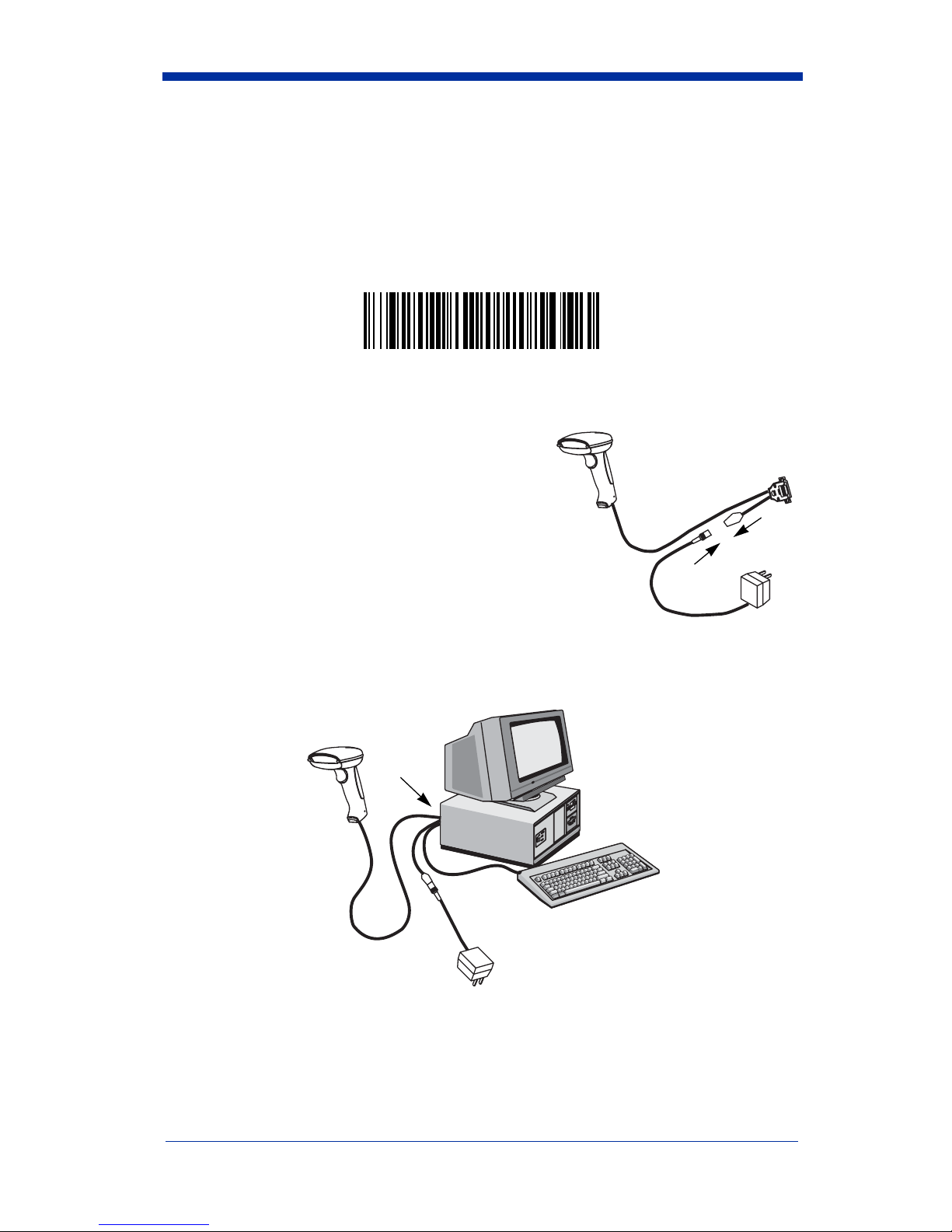
Serial Port Connection
All communication parameters between the scanner and terminal must match for
correct data transfer through the serial port using RS-232 protocol. Scanning the
RS-232 interface bar code, programs the scanner for an RS-232 interface at
9600 baud, even parity, 7 data bits, 1 stop bit (8 bit data), and adds a suffix of a
CR LF.
RS-232 Interface
1. Turn off power to the terminal/computer.
2. Connect the appropriate interface cable to
the scanner.
Note: For the scanner to work properly, you
must have the correct cable for your type
of terminal/computer.
2
3. Plug the serial connector into the serial port
on the back of your computer/terminal, as shown below. Tighten the two
screws to secure the connector to the port.
3
4. Plug the power pack into a power source.
5. Once the scanner has been fully connected, power up the terminal/
computer.
2 - 8 IT3800/3900 User’s Guide
Page 35

Baud Rate
Baud Rate sends the data from the scanner to the terminal at the specified rate.
The host terminal must be set for the same baud rate as the scanner.
Default = 9600.
300
600
1200
2400
4800
19200
* 9600
38400
IT3800/3900 User’s Guide 2 - 9
Page 36

RS-232 Word Length: Data Bits, Stop Bits, and Parity
Data Bits
application requires only ASCII Hex characters 0 through 7F decimal (text, digits,
and punctuation), select 7 data bits. For applications which require use of the full
ASCII set, select 8 data bits per character. Default = 7.
Stop Bits
Parity
Default = Even.
sets the word length at 7 or 8 bits of data per character. If an
sets the stop bits at 1 or 2. Default = 1.
provides a means of checking character bit patterns for validity.
* 7 Data, 1 Stop, Parity Even
7 Data, 1 Stop, Parity None
7 Data, 1 Stop, Parity Odd
7 Data, 1 Stop, Parity Space
7 Data, 2 Stop Parity None
7 Data, 2 Stop, Parity Mark
7 Data, 1 Stop, Parity Mark
7 Data, 2 Stop, Parity Even
7 Data, 2 Stop, Parity Odd
2 - 10 IT3800/3900 User’s Guide
Page 37

RS-232 Word Length: Data Bits, Stop Bits, and Parity
(continued)
7 Data, 2 Stop, Parity Space
8 Data, 1 Stop, Parity Even
8 Data, 1 Stop, Parity None
8 Data, 1 Stop, Parity Odd
8 Data, 1 Stop, Parity Mark
8 Data, 1 Stop, Parity Space
IT3800/3900 User’s Guide 2 - 11
Page 38

RS-232 Handshaking
RS-232 handshaking is a set of rules concerning the exchange of data between
serially communicating devices. Default = RTS/CTS, XON/XOFF and ACK/
NAK Off
RTS/CTS On
* RTS/CTS Off
XON/XOFF On
* XON/OFF Off
ACK/NAK On
* ACK/NAK Off
Wand Emulation Connection
In Wand Emulation mode, the scanner decodes the bar code then sends data in
the same format as a wand scanner. The Code 39 Format converts all
symbologies to Code 39. The Same Code Format transmits UPC, EAN, Code
128 and Interleaved 2 of 5 without any changes, but converts all other
symbologies to Code 39. These codes set the transmission rate to 25 inches per
second and the output polarity to black, high. Default = Code 39 Format.
* Code 39 Format
Same Code Format
2 - 12 IT3800/3900 User’s Guide
Page 39

Note: For the 3800PDF model: When the 3800PDF interface is set to wand
emulation, all PDF417 bar code data is transmitted as Code 128. Data
from other symbologies follow the rules described above.
Wand Emulation Transmission Rate
The Transmission Rate is limited by the terminal’s ability to receive data without
dropping characters. Default = 25 inches/second.
10
* 25
40
120
200
80
150
IT3800/3900 User’s Guide 2 - 13
Page 40

Wand Emulation Polarity
The Polarity can be sent as standard with black bars high, or reversed with white
bars high. Default = Black High.
* Black High
White High
Wand Emulation Idle
The idle describes the state of the scanner when no data is being transmitted.
When in Wand Emulation mode, you must set the scanner’s idle state to match
the idle state for the device to which the scanner is connected. Default = Idle
High.
* Idle High
Idle Low
2 - 14 IT3800/3900 User’s Guide
Page 41

PDF417 Wand Emulation
Note: The following Wand Emulation functions are for use with the 3800PDF-12
scanner only.
Data Block Size
This transmits the PDF417 data in smaller blocks to prevent buffer overflow.
Default = 60.
20
40
* 60
80
Delay Between Blocks
This sets the delay time between data blocks. Default = 50ms.
5ms
* 50ms
150ms
500ms
IT3800/3900 User’s Guide 2 - 15
Page 42

Overall Checksum
When this option is turned on, a computed check character is added at the end
of the entire message. The check character is the character which when
Exclusive-OR’d with every preceding character of the message yields a result of
0x00 (00H). Default = Off.
On
* Off
2 - 16 IT3800/3900 User’s Guide
Page 43

3
Output
Scan Rate
Adjusting the scan rate changes the current draw when scanning. The slower
the scan rate, the lower the current draw. (The standby current remains the
same.) Scan speeds are 270 s/s, 135 s/s, and 67 s/s. A scan speed of 270
draws the highest power and has the best performance. A scan speed of 135
has a medium draw with medium performance. A scan speed of 67 draws the
lowest power and has the lowest performance. Default = 270 s/s.
* 270 s/s
135 s/s
67 s/s
Beeper Volume
Default = High.
* High
Low
Medium
Off
IT3800/3900 User’s Guide 3 - 1
Page 44

Beeper Tone
Default = Normal.
* Normal Beep
Short Beep
Scan Voting
This sets the number of times the same bar code has to be read before it is
transmitted to the terminal. Normal uses the default values listed for the
symbologies in the Default Charts beginning on page 12-5. High doubles the
votes used below the threshold. Default = Voting Normal.
* Voting Normal
Voting High
Reduce Quiet Zone
Reducing the quiet zone requirements below AIM guidelines makes it possible to
read off-spec bar codes. This feature is effective with all symbologies. Default
= Don’t Reduce Quite Zone.
* Don’t Reduce Quiet Zone
Reduce Quiet Zone
3 - 2 IT3800/3900 User’s Guide
Page 45

Reread Delay
This sets the time period before the scanner can read the same bar code a
second time. Setting a reread delay protects against accidental rereads of the
same bar code. Longer delays are effective in minimizing accidental rereads at
POS (point of sale). Use shorter delays in applications where repetitive bar code
scanning is required. Default = Short.
Reread Delay only works when in automatic trigger mode (see page 3-4).
* Short
Medium
Long
Extra Long
IT3800/3900 User’s Guide 3 - 3
Page 46

Good Read Delay
This sets the minimum amount of time before the scanner can read another bar
code. Default = No Delay.
* No Delay
Short Delay
Medium Delay
Long Delay
Trigger Mode
Manual/Serial Trigger:
trigger, or using a serial trigger command (see "Trigger Commands" on page 12-
4). When in manual trigger mode, the scanner scans until a bar code is read, or
until the trigger is released.
When in serial mode, the scanner scans until a bar code has been read or until
the deactivate command is sent. In serial mode, the scanner can also be set to
turn itself off after a specified time has elapsed (see Serial Trigger Time Out,
which follows). Default for IT3800.
Manual/Serial Trigger
You can activate the scanner either by pressing the
3 - 4 IT3800/3900 User’s Guide
Page 47

Serial Trigger Time Out:
Use this selection to set a time out (in quarter
seconds) of the scanner’s trigger when using serial commands to trigger the
scanner. Once the scanner has timed out, it must be triggered again either
serially or manually. After scanning the Serial Trigger Time Out bar code, set the
time out duration (from 0-1200 quarter seconds) by scanning digits from the
inside back cover, then scanning Save. Default = 0 (infinite, or no time out).
Serial Trigger Time Out
Manual Trigger, Low Power:
The scanner “sleeps,” using only 30 milliamps,
until the trigger is pulled. When the trigger is pulled, the scanner wakes up and
operates at reduced power until there is no triggering for the time set with the Low
Power Time Out bar code. There is a short delay in operation when the scanner
is first triggered, but there is no delay when operating in low power mode.
Manual Trigger, Low Power
Note: Manual Trigger, Low Power cannot be used with keyboard wedge
applications.
Low Power Time Out:
Scan the Low Power Time Out bar code to change the
time out duration. Then scan the time out duration (from 0-300 seconds) from
the inside back cover, and Save. Default = 2 minutes.
Note: If you make an error while scanning the digits (before scanning Save),
scan Discard on the back cover, scan the Lower Power Time Out bar
code, scan the correct digits, then Save again.
Low Power Time Out
Automatic Trigger:
The scanner scans continuously at full power. Default for
IT3900.
IT3800/3900 User’s Guide 3 - 5
Automatic Trigger
Page 48

Presentation Mode:
The LEDs are off until a bar code is presented to the
scanner. Then the LEDs turn on automatically to read the code. Presentation
Mode uses normal office or store ambient light to detect the bar codes.
Presentation Mode
Note: Do not use Presentation Mode with a 3800/3900PDF. Normal office or
store ambient light does not provide enough illumination for the IT3800/
3900PDF to work properly in Presentation Mode.
3 - 6 IT3800/3900 User’s Guide
Page 49

4
Data Editing
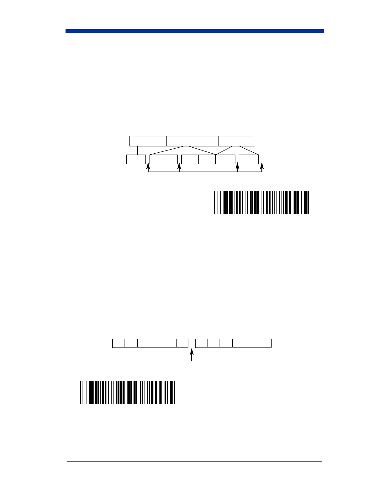
Prefix/Suffix Overview
When a bar code is scanned, additional information is sent to the host computer
along with the bar code data. This group of bar code data and additional,
user-defined data is called a “message string.” The selections in this section are
used to build the user-defined data into the message string.
Prefix and Suffix characters are data characters that can be sent before and after
scanned data. You can specify if they should be sent with all symbologies, or
only with specific symbologies. The following illustration shows the breakdown
of a message string:
Prefix
alpha numeric
characters
Scanned Data
variable length1-10
Suffix
1-10
alpha numeric
characters
Points to Keep In Mind
• It is not necessary to build a message string. The selections in this chapter
are only used if you wish to alter the default settings. Default prefix = None.
Default suffix = None.
• A prefix or suffix may be added or cleared from one symbology or all
symbologies.
• You can add any prefix or suffix from the ASCII chart (page 4-6 ), plus Code
I.D. and Aim I.D.
• You can string together several entries for several symbologies at one time.
• Enter prefixes and suffixes in the order in which you want them to appear on
the output.
To Add a Prefix or Suffix:
Step 1. Scan the Add Prefix or Add Suffix symbol (page 4-4).
Step 2. Determine the 2 digit Hex value from the Symbology Chart (page 4-5)
for the symbology to which you want to apply the prefix or suffix.
IT3800/3900 User’s Guide 4 - 1
Page 50

Step 3. Scan the 2 hex digits from the Programming Chart inside the back
cover or scan 9, 9 for all symbologies.
Step 4. Determine the hex value from the Decimal to Hex to ASCII Conversion
Chart (page 4-6) for the prefix or suffix you wish to enter.
Step 5. Scan the 2 digit hex value from the Programming Chart inside the back
cover.
Step 6. Repeat Steps 4 and 5 for every prefix or suffix character.
Step 7. To add the Code I.D., scan 5, C, 8, 0.
To add AIM I.D., scan 5, C, 8, 1.
To add a backslash (\), scan 5, C, 5, C.
Step 8. Scan Save to exit and save, or scan Discard to exit without saving.
Repeat Steps 1-6 to add a prefix or suffix for another symbology.
Example: Add a Suffix to a specific symbology
To send a CR (carriage return)Suffix for UPC only:
Step 1. Scan Add Suffix.
Step 2. Determine the 2 digit hex value from the Symbology Chart (page 4-5)
for UPC.
Step 3. Scan 6, 3 from the Programming Chart (inside back cover).
Step 4. Determine the hex value from the Decimal to Hex to ASCII Conversion
Chart (page 4-6) for the CR (carriage return).
Step 5. Scan 0, D from the Programming Chart (inside back cover).
Step 6. Scan Save, or scan Discard to exit without saving.
To Clear One or All Prefixes or Suffixes:
You can clear a single prefix or suffix, or clear all prefixes/suffixes for a
symbology. When you Clear One Prefix (Suffix), the specific character you
select is deleted from the symbology you want. When you Clear All Prefixes
(Suffixes), all the prefixes or suffixes for a symbology are deleted.
Step 1. Scan the Clear One Prefix or Clear One Suffix symbol.
Step 2. Determine the 2 digit Hex value from the Symbology Chart (page 4-5)
for the symbology from which you want to clear the prefix or suffix.
Step 3. Scan the 2 digit hex value from the Programming Chart inside the back
cover or scan 9, 9 for all symbologies.
Your change is automatically saved.
4 - 2 IT3800/3900 User’s Guide
Page 51

To Add a Carriage Return Suffix to all Symbologies
Scan the following bar code if you wish to add a Carriage Return Suffix to all
symbologies at once. This action first clears all current suffixes, then programs
a carriage return suffix for all symbologies.
Add CR Suffix
All Symbologies
IT3800/3900 User’s Guide 4 - 3
Page 52

Prefix Selections
Add Prefix
Clear All Prefixes
Suffix Selections
Add Suffix
Clear One Prefix
Clear All Suffixes
Discard
Clear One Suffix
Save
4 - 4 IT3800/3900 User’s Guide
Page 53

Symbology Chart
Symbology
China Postal
Codabar
Code 2 of 5
Code 11
Code 39
Code 32 PARAF
Code 93
Code 128
EAN/JAN
•UCC
EAN
Composite
IATA 2 of 5
Note:
Prefix/Suffix entries for specific symbologies override the universal (All
CodeIDAIMIDHex
ID
q]X071
a]F061
f]S066
h]H068
b]A062
w]X077
i]G069
j]C06A
d]E064
y ]e0 79
f]R066
Symbology
Interleaved 2 of 5
Matrix 2 of 5
MicroPDF417
MSI
PDF417
Plessey
RSS-14
Telepen
UPC
All Symbologies
CodeIDAIMIDHex
e]l065
m]X06D
R ]L0 52
g]M067
r ]L0 72
n]P06E
y ]e0 79
t]B074
c]E063
Symbologies, 99) entry.
ID
99
IT3800/3900 User’s Guide 4 - 5
Page 54

ASCII Conversion Chart (Code Page 1252)
Note: This table applies to U.S. style keyboards. Certain characters may differ
depending on your Country Code/PC regional settings.
Dec Hex Char Dec Hex Char Dec Hex Char Dec Hex Char
0 00 NUL 32 20 64 40 @ 96 60 ‘
1 01 SOH 33 21 ! 65 41 A 97 61 a
2 02 STX 34 22 “ 66 42 B 98 62 b
3 03 ETX 35 23 # 67 43 C 99 63 c
4 04 EOT 36 24 $ 68 44 D 100 64 d
5 05 ENQ 37 25 % 69 45 E 101 65 e
6 06 ACK 38 26 & 70 46 F 102 66 f
7 07 BEL 39 27 ‘ 71 47 G 103 67 g
8 08 BS 40 28 ( 72 48 H 104 68 h
9 09 HT 41 29 ) 73 49 l 105 69 i
10 0A LF 42 2A * 74 4A J 106 6A j
11 0B VT 43 2B + 75 4B K 107 6B k
12 0C FF 44 2C , 76 4C L 108 6C l
13 0D CR 45 2D - 77 4D M 109 6D m
14 0E SO 46 2E . 78 4E N 110 6E n
15 0F SI 47 2F / 79 4F O 111 6F o
16 10 DLE 48 30 0 80 50 P 112 70 p
17 11 DC1 49 31 1 81 51 Q 113 71 q
18 12 DC2 50 32 2 82 52 R 114 72 r
19 13 DC3 51 33 3 83 53 S 115 73 s
20 14 DC4 52 34 4 84 54 T 116 74 t
21 15 NAK 53 35 5 85 55 U 117 75 u
22 16 SYN 54 36 6 86 56 V 118 76 v
23 17 ETB 55 37 7 87 57 W 119 77 w
24 18 CAN 56 38 8 88 58 X 120 78 x
25 19 EM 57 39 9 89 59 Y 121 79 y
26 1A SUB 58 3A : 90 5A Z 122 7A z
27 1B ESC 59 3B ; 91 5B [ 123 7B {
28 1C FS 60 3C < 92 5C \ 124 7C |
29 1D GS 61 3D = 93 5D ] 125 7D }
30 1E RS 62 3E > 94 5E ^ 126 7E ~
31 1F US 63 3F ? 95 5F _ 127 7F
4 - 6 IT3800/3900 User’s Guide
Page 55

Dec Hex Char Dec Hex Char Dec Hex Char Dec Hex Char
128 80
€
€
160 A0 192 C0 À 224 E0 à
129 81 161 A1 ¡ 193 C1 Á 225 E1 á
130 82 ‚ 162 A2 ¢ 194 C2 Â 226 E2 â
131 83 ƒ 163 A3 £ 195 C3 Ã 227 E3 ã
132 84 „ 164 A4 ¤ 196 C4 Ä 228 E4 ä
133 85 … 165 A5 ¥ 197 C5 Å 229 E5 å
134 86 † 166 A6 ¦ 198 C6 Æ 230 E6 æ
135 87 ‡ 167 A7 § 199 C7 Ç 231 E7 ç
136 88 ˆ 168 A8 ¨ 200 C8 È 232 E8 è
137 89 ‰ 169 A9 © 201 C9 É 233 E9 é
138 8A Š 170 AA 202 CA Ê 234 EA ê
ª
139 8B ‹ 171 AB « 203 CB Ë 235 EB ë
140 8C Œ 172 AC ¬ 204 CC Ì 236 EC ì
141 8D 173 AD - 205 CD Í 237 ED í
142 8E Ž 174 AE ® 206 CE Î 238 EE î
143 8F 175 AF ¯ 207 CF Ï 239 EF ï
144 90 176 B0 ° 208 D0 Ð 240 F0 ð
145 91 ‘ 177 B1 ± 209 D1 Ñ 241 F1 ñ
146 92 ’ 178 B2 ² 210 D2 Ò 242 F2 ò
147 93 “ 179 B3 ³ 211 D3 Ó 243 F3 ó
148 94 ” 180 B4 ´ 212 D4 Ô 244 F4 ô
149 95 • 181 B5 µ 213 D5 Õ 245 F5 õ
150 96 – 182 B6 ¶ 214 D6 Ö 246 F6 ö
151 97 — 183 B7 · 215 D7 × 247 F7 ÷
152 98 ˜ 184 B8 ¸ 216 D8 Ø 248 F8 ø
153 99 ™ 185 B9 ¹ 217 D9 Ù 249 F9 ù
154 9A š 186 BA 218 DA Ú 250 FA ú
155 9B › 187 BB » 219 DB Û 251 FB û
156 9C œ 188 BC ¼ 220 DC Ü 252 FC ü
157 9D 189 BD ½ 221 DD Ý 253 FD ý
158 9E ž 190 BE ¾ 222 DE Þ 254 FE þ
159 9F Ÿ 191 BF ¿ 223 DF ß 255 FF ÿ
IT3800/3900 User’s Guide 4 - 7
Page 56

Function Code Transmit
When this selection is enabled and function codes are contained within the
scanned data, the scanner transmits the function code to the terminal. Charts of
these function codes are provided in Section 10, Supported Interface Keys.
When the scanner is in keyboard wedge mode, the scan code is converted to a
key code before it is transmitted. Default = Enable.
* Enable
Disable
Intercharacter, Interfunction, and Intermessage Delays
Some terminals drop information (characters) if data comes through too quickly.
Intercharacter, interfunction, and intermessage delays slow the transmission of
data, increasing data integrity.
Each delay is composed of a 5 millisecond step. You can program up to 99 steps
(of 5 ms each).
Intercharacter Delay
This is a delay of up to 495 milliseconds (in multiples of 5) placed between the
transmission of each character of scanned data. You can program up to 99 steps
(of 5 ms each). Scan the Intercharacter Delay bar code below, then scan the
number of steps, and the SAVE bar code from the inside back cover.
4 - 8 IT3800/3900 User’s Guide
Page 57

Note: If you make an error while scanning the digits (before scanning Save),
Discard
scan
scan the correct digits, and
To remove this delay, scan the Intercharacter Delay bar code, then set the
number of steps to 00. Scan the SAVE bar code from the inside back cover.
on the back cover, scan the Intercharacter Delay bar code,
Save
Prefix Scanned Data Suffix
1 2345
Intercharacter Delay
again.
Intercharacter Delay
User Specified Intercharacter Delay
This is a delay of up to 495 milliseconds (in multiples of 5) placed after the
transmission of a particular character of scanned data. You can program up to
99 steps (of 5 ms each) to follow the character you specify. Scan the Delay
Length bar code below, then the number of steps for the delay, and the SAVE
bar code from the inside back cover.
Next, scan the Character to Trigger Delay bar code, then the 2 digit hex value for
the ASCII character that will trigger the delay (refer to the Decimal to Hex to
ASCII conversion chart on page 4-5).
Note: If you make an error while scanning the digits (before scanning Save),
scan Discard on the inside back cover, scan the Character to Trigger
Delay bar code, scan the correct digits, and Save again.
Delay Length
Character to Trigger Delay
To remove this delay, scan the Delay Length bar code, and set the number of
steps to 00. Scan the SAVE bar code from the inside back cover.
IT3800/3900 User’s Guide 4 - 9
Page 58
Interfunction Delay
This is a delay of up to 495 milliseconds (in multiples of 5) placed between the
transmission of each segment of the message string. You can program up to 99
steps (of 5 ms each). Scan the Interfunction Delay bar code below, then scan
the number of steps, and the SAVE bar code from the inside back cover.
Note: If you make an error while scanning the
digits (before scanning Save), scan Discard on the inside back cover,
scan the Interfunction Delay bar code, scan the correct digits, and Save
again.
Prefix Scanned Data Suffix
1 2345STX HT CR LF
Interfunction Delays
Interfunction Delay
To remove this delay, scan the Interfunction Delay bar code, then set the number
of steps to 00. Scan the SAVE bar code from the inside back cover.
Intermessage Delay
This is a delay of up to 495 milliseconds (in multiples of 5) placed between each
scan transmission. You can program up to 99 steps (of 5 ms each). Scan the
Intermessage Delay bar code below, then scan the number of steps, and the
SAVE bar code from the inside back cover.
Note: If you make an error while scanning the digits (before scanning Save),
scan Discard on the inside back cover, scan the Intermessage Delay bar
code, scan the correct digits, and Save again.
2nd Scan Transmission1st Scan Transmission
Intermessage Delay
Intermessage Delay
To remove this delay, scan the Intermessage Delay bar code, then set the
number of steps to 00. Scan the SAVE bar code from the inside back cover.
4 - 10 IT3800/3900 User’s Guide
Page 59

5
Data Formatting
Data Format Editor Introduction
The Data Format Editor selections are used to edit scanned data. For example,
you can use the Data Format Editor to insert characters at certain points in bar
code data as it is scanned. It is not necessary to use the Data Format Editor. A
set of defaults for the data format is already programmed in the scanner. The
selections in the following pages are used only if you wish to alter the default
settings. Default Data Format setting = None.
Normally, when you scan a bar code, it gets outputted automatically; however
when you do a format, you must use a “send” command (see Send Commands
on page 5-2) within the format program to output data.
Multiple formats may be programmed into the imager. They are stacked in the
order in which they are entered. However, the following list presents the order
in which formats are applied:
1. Specific Term ID, Actual Code ID, Actual Length
2. Specific Term ID, Actual Code ID, Universal Length
3. Specific Term ID, Universal Code ID, Actual Length
4. Specific Term ID, Universal Code ID, Universal Length
5. Universal Term ID, Actual Code ID, Actual Length
6. Universal Term ID, Actual Code ID, Universal Length
7. Universal Term ID, Universal Code ID, Actual Length
8. Universal Term ID, Universal Code ID, Universal Length
If you have changed data format settings, and wish to clear all formats and return
to the defaults, scan the Default Data Format code on page 5-4.
To Add a Data Format
Step 1. Scan the Enter Data Format symbol (page 5-4).
Step 2. Primary/Alternate Format
Determine if this will be your primary data format, or one of 3 alternate
formats. (Alternate formats allow you “single shot” capability to scan
one bar code using a different data format. After the one bar code has
been read, the scanner reverts to the primary data format. See page 5-
5.) If you are programming the primary format, scan 0. If you are pro-
gramming an alternate format, scan 1, 2, or 3, depending on the alternate format you are programming.
Step 3. Terminal Type
Refer to the Supported Terminals Chart (page 2-3) and locate the Terminal ID number for your PC. Scan three numeric bar codes on the
inside back cover to program the scanner for your terminal ID (you must
enter 3 digits). For example, scan 0 0 3 for an AT wedge.
IT3800/3900 User’s Guide 5 - 1
Page 60

Note: The wildcard for all terminal types is 099.
Step 4. Code I.D.
On page 4-5, find the symbology to which you want to apply the data
format. Locate the Hex value for that symbology and scan the 2 digit
hex value from the Programming Chart.
Step 5. Length
Specify what length (up to 9999 characters) of data will be acceptable
for this symbology. Scan the four digit data length from the Programming Chart. (Note: 50 characters is entered as 0050. 9999 is a universal number, indicating all lengths.)
Step 6. Editor Commands
Refer to the Format Editor Commands Chart (page 5-2). Scan the sym-
bols that represent the command you want to enter. 94 alphanumeric
characters may be entered for each symbology data format.
Step 7. Scan Save to save your entries.
Other Programming Selections
• Clear One Data Format
This deletes one data format for one symbology. If you are clearing the
primary format, scan 0. If you are clearing an alternate format, scan 1, 2, or
3, depending on the alternate format you are clearing. Scan the Terminal
Type (refer to the Supported Terminals Chart on page 2-3), Code I.D. and the
length of the format you want to delete. That length data format for that
symbology is deleted and all other formats are unaffected.
• Save
This exits, saving any Data Format changes.
• Discard
This exits without saving any Data Format changes.
Data Format Editor Commands
Send Commands
F1 Send all characters followed by “xx” key or function code, starting from cur-
rent cursor position.
ASCII code, see Decimal to Hex to ASCII Conversion chart, page 4-6.)
F2 Send “nn” characters followed by “xx” key or function code, starting from
current cursor position.
(00-99) for the number of characters and xx stands for the hex value for an
ASCII code. See Decimal to Hex to ASCII Conversion chart, page 4-6.)
F3 Send up to but not including “ss” character (Search and Send) starting from
current cursor position, leaving cursor pointing to “ss” character followed by
“xx” key or function code.
hex values for ASCII codes, see Decimal to Hex to ASCII Conversion chart,
page 4-6.)
5 - 2 IT3800/3900 User’s Guide
Syntax = F1xx
Syntax = F2nnxx
Syntax = F3ssxx
(xx stands for the hex value for an
(nn stands for the numeric value
(ss and xx both stand for the
Page 61

F4 Send “xx” character “nn” times (Insert) leaving cursor in current cursor posi-
Syntax = F4xxnn
tion.
Decimal to Hex to ASCII Conversion chart, page 4-6, and nn is the numeric
value (00-99) for the number of times it should be sent.)
E9 Send all but the last “nn” characters, starting from the current cursor posi-
Syntax = E9nn
tion.
characters that will not be sent at the end of the message.)
(xx stands for the hex value for an ASCII code, see
(nn is the numeric value (00-99) for the number of
Move Commands
F5 Move the cursor ahead “nn” characters from current cursor position.
Syntax = F5nn
characters the cursor should be moved ahead.)
F6 Move the cursor back “nn” characters from current cursor position.
Syntax = F6nn
characters the cursor should be moved back.)
F7 Move the cursor to the beginning of the data string.
EA Move the cursor to the end of the data string.
(nn stands for the numeric value (00-99) for the number of
(nn stands for the numeric value (00-99) for the number of
Syntax = F7
.
Syntax = EA
Search Commands
F8 Search ahead for “xx” character from current cursor position, leaving cursor
pointing to “xx” character.
an ASCII code, see Decimal to Hex to ASCII Conversion chart, page 4-6.)
F9 Search back for “xx” character from current cursor position, leaving cursor
pointing to “xx” character.
an ASCII code, see Decimal to Hex to ASCII Conversion chart, page 4-6.)
E6 Search ahead for the first non “xx” character from the current cursor posi-
tion, leaving cursor pointing to non “xx” character.
stands for the hex value for an ASCII code, see Decimal to Hex to ASCII
Conversion chart, page 4-6.)
E7 Search back for the first non “xx” character from the current cursor position,
leaving cursor pointing to non “xx” character.
the hex value for an ASCII code, see Decimal to Hex to ASCII Conversion
chart, page 4-6.)
Syntax = F8xx
Syntax = F9xx
(xx stands for the hex value for
(xx stands for the hex value for
Syntax = E6xx
Syntax = E7xx
(xx
(xx stands for
Miscellaneous Commands
FB Suppress all occurrences of up to 15 different characters, starting at the cur-
rent cursor position, as the cursor is advanced by other commands. When
the FC command is encountered, the suppress function is terminated. The
cursor is not moved by the FB command. Syntax = FBnnxxyy . .zz where
nn is a count of the number of suppressed characters in the list and xxyy ..
zz is the list of characters to be suppressed. (xx stands for the hex value for
an ASCII code, see Decimal to Hex to ASCII Conversion chart, page 4-6.)
FC Disables suppress filter and clear all suppressed characters.
E4 Replaces up to 15 characters in the data string with user specified charac-
ters. Replacement continues until the E5 command is encountered.
tax = E4nnxx1xx2yy1yy2...zz1zz
characters to be replaced plus replacement characters; xx
IT3800/3900 User’s Guide 5 - 3
Syntax = FC
where nn is the total count of both
2
defines charac-
1
.
Syn-
Page 62

ters to be replaced and xx2 defines replacement characters, continuing
through zz
E5 Terminates character replacement.
FE Compare character in current cursor position to the character “xx.” If char-
acters are equal, increment cursor. If characters are not equal, no format
match.
Decimal to Hex to ASCII Conversion chart, page 4-6.)
EC Check to make sure there is an ASCII number at the current cursor position.
If character is not numeric, format is aborted.
ED Check to make sure there is a non-numeric ASCII character at the current
cursor position. If character is numeric, format is aborted.
and zz2.
1
Syntax = FExx
Syntax = E5
(xx stands for the hex value for an ASCII code, see
.
Syntax = EC
.
Syntax = ED
.
Data Format Editor
Enter Data Format
Default Data Format
Clear One Data Format
Save
Clear All Data Formats
Discard
5 - 4 IT3800/3900 User’s Guide
Page 63

Data Formatter
When Data Formatter is turned off, the bar code data is output to the host as read
(including prefixes and suffixes). Choose one of the following options. Default =
Data Formatter On.
* Data Formatter On,
but Not Required
Data Formatter Off
When Data Formatter is required, all input data must conform to an edited format
or the scanner does not transmit the input data to the host device.
Data Format On, Format Required
Alternate Data Formats
Alternate formats allow you “single shot” capability to scan one bar code using a
different data format than your primary format. When data formats are
programmed (see page 5-1), you must input whether you are programming the
primary format, or an alternate format numbered 1, 2, or 3.
An alternate format is initiated by scanning one of the 3 alternate format bar
codes below. The scanner will scan the next bar code, formatting the data with
the selected alternate format, then revert immediately to the primary format.
Alternate Data Format 1
Alternate Data Format 2
Alternate Data Format 3
IT3800/3900 User’s Guide 5 - 5
Page 64

5 - 6 IT3800/3900 User’s Guide
Page 65

6
Secondary Interface
By switching interface cables, the IT3800/3900 scanner can communicate with
a portable data terminal (secondary interface), in addition to the host terminal
(primary interface).
Note: Secondary interfaces do not apply to the IT3800LX-15.
The secondary interface can be programmed at any time.
Secondary Code 39 Wand Emulation
In Wand Emulation mode, the scanner decodes the bar code then sends data in
the same format as a wand scanner. The Code 39 Format converts all
symbologies to Code 39. The Same Code Format transmits UPC, EAN, Code
128 and Interleaved 2 of 5 without any changes, but converts all other
symbologies to Code 39. These codes set the transmission rate to 25 inches per
second and the output polarity to black, high. Default = Code 39 Format.
* Wand Emulation
Code 39 Format
Wand Emulation
Same Code Format
Note for the 3800PDF model: When the 3800PDF interface is set to wand
emulation, all PDF417 bar code data is transmitted as Code 128. Data from
other symbologies follow the rules described above.
Secondary RS-232 Connection
All communication parameters between the scanner and terminal must match for
correct data transfer through the serial port using RS-232 protocol.
RS-232 programmable selections are used by both the primary and secondary
interfaces. Changing an RS-232 parameter (e.g., baud rate or parity), while in
primary or secondary mode will affect both interfaces.
RS-232 Interface
IT3800/3900 User’s Guide 6 - 1
Page 66

Secondary Non Decoded Output Laser Emulation
Use this selection when connecting to a secondary terminal with integral
decoding. This also sets the transmission rate to 36 scans per second and the
polarity to white high.
Non Decoded Output
Non Decoded Output Laser Emulation Transmission
Rate
The Transmission Rate is limited by the terminal’s ability to receive data without
dropping characters. Default = 36 scans/second.
* 36
100
Non Decoded Output Laser Emulation Polarity
The Polarity can be sent as standard with white bars high, or reversed with black
bars high. Default = White High.
* White High
Black High
6 - 2 IT3800/3900 User’s Guide
Page 67

Non Decoded Laser Emulation Idle
The idle describes the state of the scanner when no data is being transmitted.
When in Non Decoded mode, you must set the scanner’s idle state to match the
idle state for the device to which the scanner is connected. Default = High.
Low
* High
Disabling the Secondary Interface
You can temporarily disable the secondary interface, but still retain the
secondary interface settings in the scanner’s memory by scanning the Disable
bar code below. To re-enable the secondary interface, scan the Enable bar
code. Default =Disable.
* Disable
Enable
Secondary Trigger Mode
Manual Trigger:
scanning, idle power is maintained. Default = Manual Trigger.
* Manual Trigger
You must press the scanner trigger to scan. When not
IT3800/3900 User’s Guide 6 - 3
Page 68

Automatic Trigger:
The scanner scans continuously at full power.
Automatic Trigger
Manual Trigger, Low Power:
The scanner “sleeps,” using only 30 milliamps,
until the trigger is pulled. When the trigger is pulled, the scanner wakes up and
operates at normal power until there is no triggering for the time set with the Low
Power Time Out bar code. Then, the scanner goes to “sleep” again.
Low Power Time Out:
Scan the Low Power Time Out bar code to change the
time out duration. Then scan the time out duration (from 0-300 seconds) from
the inside back cover and Save. Default = 2 minutes.
Note: If you make an error while scanning the digits (before scanning Save),
scan Discard on the back cover, scan the Low Power Time Out bar code,
scan the correct digits, and Save again.
Manual Trigger, Low Power
Low Power Time Out
Note: The Secondary Manual Trigger, Lower Power option is not available on
the 3800LR-11 in Secondary Non-Decoded Out Laser Emulation Mode.
6 - 4 IT3800/3900 User’s Guide
Page 69

7
Symbologies
Introduction
Use this section to program the scanner for Industrial, Retail, and PDF417
Symbology selections.
This programming section contains the following menu selections:
• All Symbologies • IATA Code 2 of 5
• China Post Code • Interleaved 2 of 5
• Codabar • Matrix 2 of 5
• Code 2 of 5 • MicroPDF417
• Code 11 • MSI
• Code 39 • PDF417
• Code 32 PARAF • Plessey
• Code 93 • RSS-14
• Code 128 • Telepen
• EAN/JAN • UPC
• EAN•UCC Composite
All Symbologies
If you want to decode all the symbologies allowable for your scanner, scan the
All Symbologies On
All Symbologies On
code.
All Symbologies Off
IT3800/3900 User’s Guide 7 - 1
Page 70

Message Length Description
You are able to set the valid reading length of some of the bar code symbologies.
If the data length of the scanned bar code doesn’t match the valid reading length,
the imager will issue an error beep. You may wish to set the same value for
minimum and maximum length to force the imager to read fixed length bar code
data. This helps reduce the chances of a misread.
EXAMPLE:Decode only those bar codes with a count of 9-20 characters.
Min. length = 09 Max. length = 20
EXAMPLE:Decode only those bar codes with a count of 15 characters.
Min. length = 15 Max. length = 15
For a value other than the minimum and maximum message length defaults,
scan the bar codes included in the explanation of the symbology, then scan the
digit value of the message length and Save bar codes on the Programming Chart
inside the back cover of this manual. The minimum and maximum lengths and
the defaults are included with the respective symbologies.
7 - 2 IT3800/3900 User’s Guide
Page 71

Codabar
Codabar
<Default All Codabar Settings>
* On
Off
Start/Stop Characters
Start/Stop characters identify the leading and trailing ends of the bar code. You
may either transmit, or not transmit Start/Stop characters.
Default = Don’t Transmit.
Transmit
* Don’t Transmit
IT3800/3900 User’s Guide 7 - 3
Page 72

Codabar (continued)
Check Character
Codabar check characters are created using different “modulos.” You can
program the scanner to read only Codabar bar codes with Modulo 16 check
characters. Default = No Check Character.
No Check Character
data with or without a check character.
When Check Character is set to
read Codabar bar codes printed with a check character, and will transmit this
character at the end of the scanned data.
When Check Character is set to
read Codabar bar codes printed
check character with the scanned data.
* No Check Character
Validate Modulo 16 and Transmit
indicates that the scanner reads and transmits bar code
Validate and Transmit
V alidate, but Don’t Transmit
with
a check character, but will not transmit the
Validate Modulo 16, but
, the scanner will only
, the unit will only
Don’t Transmit
7 - 4 IT3800/3900 User’s Guide
Page 73

Concatenation
Codabar supports symbol concatenation. When you
Enable
concatenation, the
scanner looks for a Codabar symbol having a “D” start character, adjacent to a
symbol having a “D” stop character. In this case the two messages are
concatenated into one with the “D” characters omitted. Default = On.
Character
Stop Start StopStart
Codabar
A12D D34A
Select
Require
to prevent the scanner from decoding a lone Codabar symbol.
* On
Off
Require
Codabar Message Length
Scan the bar codes below to change the message length. Refer to Message
Length Description (page 7-2) for additional information. Minimum and
Maximum lengths = 2-60. Minimum Default = 4, Maximum Default = 60.
Minimum Message Length
Maximum Message Length
IT3800/3900 User’s Guide 7 - 5
Page 74
Code 39
Code 39
< Default All Code 39 Settings >
* On
Off
Start/S top Characters
Start/Stop characters identify the leading and trailing ends of the bar code. You
may either transmit, or not transmit Start/Stop characters. Default = Don’t
Transmit.
Transmit
* Don’t Transmit
7 - 6 IT3800/3900 User’s Guide
Page 75

Code 39, continued
Check Character
No Check Character indicates that the scanner reads and transmits bar code
data with or without a check character.
When Check Character is set to V alidate, but Don’t Transmit, the unit will only
with
read Code 39 bar codes printed
check character with the scanned data.
When Check Character is set to Validate and Transmit, the scanner will only
read Code 39 bar codes printed with a check character, and will transmit this
character at the end of the scanned data. Default = No Check Character.
* No Check Character
a check character, but will not transmit the
Validate, but Don’t Transmit
Validate and Transmit
Code 39 Message Length
Scan the bar codes below to change the message length. Refer to Message
Length Description (page 7-2) for additional information. Minimum and
Maximum lengths = 0-48. Minimum Default = 0, Maximum Default = 48.
Minimum Message Length
Maximum Message Length
IT3800/3900 User’s Guide 7 - 7
Page 76

Code 39 Append
This function allows the scanner to append the data from several Code 39 bar
codes together before transmitting them to the host computer. When this
function is enabled, the scanner stores those Code 39 bar codes that start with
a space (excluding the start and stop symbols), and does not immediately
transmit the data. The scanner stores the data in the order in which the bar
codes are read, deleting the first space from each. The scanner transmits the
appended data when it reads a Code 39 bar code that starts with a character
other than a space. Default = Off.
On
* Off
Base 32
Base 32 is a form of the Code 39 symbology used by Italian pharmacies. This is
also known as PARAF.
On
* Off
7 - 8 IT3800/3900 User’s Guide
Page 77

Code 39, continued
Full ASCII
If Full ASCII Code 39 decoding is enabled, certain character pairs within the bar
code symbol will be interpreted as a single character. For example: $V will be
decoded as the ASCII character SYN, and /C will be decoded as the ASCII
character #. Default = On.
NUL %U DLE $P
SOH $A DC1 $Q !/A 11AAQQa+Aq+Q
STX $B
ETX $C DC3 $S #/C 33CCSSc+Cs+S
EOT $D DC4 $T $/D 44DDTTd+Dt+T
ENQ $E
ACK $F SYN $V &/F 66FFVVf+Fv+V
BEL $G ETB $W ‘/G77GGWWg+Gw+W
BS $H
HT $I EM $Y )/I 99IIYYi+Iy+Y
LF $J SUB $Z */J :/ZJJZZj+Jz+Z
VT $K
FF $L
CR $M GS %C -- =%HMM]%Mm+M}%R
SO $N RS %D .. >%INN^%Nn+N~%S
SI $O
DC2 $R “/B 22BBRRb+Br+R
NAK $U %/E 55EEUUe+Eu+U
CAN $X (/H 88HHXXh+Hx+X
ESC %A +/K ;%FKK[%Kk+K{%P
FS %B ,/L <%GLL\%Ll+L|%Q
US %E //O?%JOO_%Oo+ODEL %T
SP SPA CE
00@%VPP‘%Wp+P
Character pairs /M and /N decode as a minus sign and period respectively.
Character pairs /P through /Y decode as 0 through 9.
* Full ASCII On
IT3800/3900 User’s Guide 7 - 9
Full ASCII Off
Page 78

Interleaved 2 of 5
< Default All Interleaved 2 of 5 Settings >
Interleaved 2 of 5
* On
Off
Check Digit
No Check Digit indicates that the scanner reads and transmits bar code data with
or without a check digit.
When Check Digit is set to V alidate, but Don’t Transmit, the unit will only read
with
Interleaved 2 of 5 bar codes printed
check digit with the scanned data.
When Check Digit is set to Validate and Transmit, the scanner will only read
Interleaved 2 of 5 bar codes printed with a check digit, and will transmit this digit
at the end of the scanned data. Default = No Check Digit.
* No Check Digit
Validate and Transmit
a check digit, but will not transmit the
Validate, but Don’t Transmit
7 - 10 IT3800/3900 User’s Guide
Page 79

Interleaved 2 of 5, continued
Interleaved 2 of 5 Message Length
Note: Scan the bar codes below to change the message length. Refer to
Message Length Description (page 7-2) for additional information.
Minimum and Maximum lengths = 2-80. Minimum Default = 4, Maximum
Default = 80.
Minimum Message Length
Maximum Message Length
Strict Decoding
When Strict Decoding is used, the scanner only reads bar codes that are close
to spec. This reduces the number of misreads, but also reduces the tolerance
for bar codes that are slightly out of spec.
On
* Off
IT3800/3900 User’s Guide 7 - 11
Page 80
Code 93
Code 93
< Default All Code 93 Settings >
* On
Off
Code 93 Message Length
Note: Scan the bar codes below to change the message length. Refer to
Message Length Description (page 7-2) for additional information.
Minimum and Maximum lengths = 0-80. Minimum Default = 0, Maximum
Default = 80.
Minimum Message Length
Maximum Message Length
7 - 12 IT3800/3900 User’s Guide
Page 81
Code 2 of 5
<Default All Code 2 of 5 Settings>
Code 2 of 5
* On
Code 2 of 5 Message Length
Off
Note: Scan the bar codes below to change the message length. Refer to
Message Length Description (page 7-2) for additional information.
Minimum and Maximum lengths = 1-48. Minimum Default = 4, Maximum
Default = 48.
Minimum Message Length
Maximum Message Length
IATA Code 2 of 5
<Default All Code IATA 2 of 5 Settings>
IT3800/3900 User’s Guide 7 - 13
Page 82

IATA Code 2 of 5
* On
Off
IATA Code 2 of 5 Message Length
Note: Scan the bar codes below to change the message length. Refer to
Message Length Description (page 7-2) for additional information.
Minimum and Maximum lengths = 1-48. Minimum Default = 4, Maximum
Default = 48.
Minimum Message Length
Matrix 2 of 5
Maximum Message Length
<Default All Matrix 2 of 5 Settings>
7 - 14 IT3800/3900 User’s Guide
Page 83

Matrix 2 of 5
* On
Off
Matrix 2 of 5 Message Length
Note: Scan the bar codes below to change the message length. Refer to
Message Length Description (page 7-2) for additional information.
Minimum and Maximum lengths = 1-80. Minimum Default = 4, Maximum
Default = 80.
Minimum Message Length
Maximum Message Length
IT3800/3900 User’s Guide 7 - 15
Page 84

Code 11
Code 11
<Default All Code 11 Settings>
* On
Off
Check Digits Required
This option sets whether 1 or 2 check digits are required with Code 11 bar codes.
Default = Two Check Digits.
One Check Digit
* Two Check Digits
7 - 16 IT3800/3900 User’s Guide
Page 85

Code 11 Message Length
Note: Scan the bar codes below to change the message length. Refer to
Message Length Description (page 7-2) for additional information.
Minimum and Maximum lengths = 1-80. Minimum Default = 4, Maximum
Default = 80.
Minimum Message Length
Maximum Message Length
IT3800/3900 User’s Guide 7 - 17
Page 86

Code 128
Code 128
<Default All Code 128 Settings>
* On
Off
<GS> Substitution
When enabled, the scanner substitutes a <GS> for Function Character 1 when
decoding EAN 128. Default =Off.
On
* Off
7 - 18 IT3800/3900 User’s Guide
Page 87

Code 128 Message Length
Note: Scan the bar codes below to change the message length. Refer to
Message Length Description (page 7-2) for additional information.
Minimum and Maximum lengths = 0-80. Minimum Default = 0, Maximum
Default = 80.
Minimum Message Length
Maximum Message Length
Telepen
<Default All Telepen Settings>
IT3800/3900 User’s Guide 7 - 19
Page 88

Telepen
* On
Off
Telepen Output
Using AIM Telepen Output, the scanner reads symbols with start/stop pattern 1
and decodes them as standard full ASCII (start/stop pattern 1). When Original
Telepen Output is selected, the scanner reads symbols with start/stop pattern 1
and decodes them as compressed numeric with optional full ASCII (start/stop
pattern 2). Default = AIM Telepen Output.
* AIM Telepen Output
Original Telepen Output
Telepen Message Length
Note: Scan the bar codes below to change the message length. Refer to
Message Length Description (page 7-2) for additional information.
Minimum and Maximum lengths = 1-60. Minimum Default = 1, Maximum
Default = 60.
Minimum Message Length
Maximum Message Length
7 - 20 IT3800/3900 User’s Guide
Page 89

UPC A
UPC A
<Default All UPC A Settings>
* On
Off
Check Digit
This selection allows you to specify whether the check digit should be transmitted
at the end of the scanned data or not. Default = On.
* On
Off
Number System
The numeric system digit of a UPC symbol is normally transmitted, but the unit
can be programmed so it will not transmit it. Default = On.
* On
IT3800/3900 User’s Guide 7 - 21
Off
Page 90

UPC A, continued
Addenda
This selection adds 2 or 5 digits to the end of all scanned UPC A data.
Default = Off for both 2 Digit and 5 Digit Addenda.
2 Digit Addenda On
* 2 Digit Addenda Off
5 Digit Addenda On
* 5 Digit Addenda Off
Addenda Required
When Addenda Required is set to on, the scanner will only read UPC A bar
codes that have addenda. Default = Off.
Required
* Not Required
7 - 22 IT3800/3900 User’s Guide
Page 91

UPC A, continued
Addenda Separator
When this feature is on, there is a space between the data from the bar code and
the data from the addenda. When turned off, there is no space.
Default = On.
* On
Off
UPC Strict Decoding
When UPC Strict Decoding is used, the scanner only reads bar codes that are
close to spec. This reduces the number of misreads, but also reduces the
tolerance for bar codes that are slightly out of spec.
On
* Off
IT3800/3900 User’s Guide 7 - 23
Page 92

UPC E
<Default All UPC E Settings>
UPC E0 and UPC E1
Most UPC bar codes lead with the 0 number system. For these codes, use the
UPC E0 selection. If you need to read codes that lead with the 1 number system,
use the UPC E1 selection. Default = On (UPC E0) and Off (UPC E1).
* UPC E0 On
UPC E0 Off
UPC E1 On
* UPC E1 Off
UPC E Expand
UPC E Expand expands the UPC E code to the 12 digit, UPC A format.
Default = Off.
On
* Off
7 - 24 IT3800/3900 User’s Guide
Page 93

UPC E, continued
Check Digit
Check Digit specifies whether the check digit should be transmitted at the end of
the scanned data or not. Default = On.
* On
Off
Number System
The numeric system digit of a UPC symbol is normally transmitted, but the unit
can be programmed so it will not transmit it. Default = On.
* On
Off
IT3800/3900 User’s Guide 7 - 25
Page 94

UPC E, continued
Addenda
This selection adds 2 or 5 digits to the end of all scanned UPC E data.
Default = Off for both 2 Digit and 5 Digit Addenda.
2 Digit Addenda On
* 2 Digit Addenda Off
5 Digit Addenda On
* 5 Digit Addenda Off
Addenda Required
When Addenda Required is set to on, the scanner will only read UPC E bar
codes that have addenda. Default = Off.
Required
* Not Required
7 - 26 IT3800/3900 User’s Guide
Page 95

UPC E, continued
Addenda Separator
When this feature is on, there is a space between the data from the bar code and
the data from the addenda. When turned off, there is no space.
Default = On.
* On
Off
IT3800/3900 User’s Guide 7 - 27
Page 96

EAN/JAN 13
EAN/JAN 13
<Default All EAN/JAN Settings>
* On
Off
Check Digit
This selection allows you to specify whether the check digit should be transmitted
at the end of the scanned data or not. Default = On.
* On
Off
7 - 28 IT3800/3900 User’s Guide
Page 97

EAN/JAN 13, continued
Addenda
This selection adds 2 or 5 digits to the end of all scanned EAN/JAN 13 data.
Default = Off for both 2 Digit and 5 Digit Addenda.
2 Digit Addenda On
* 2 Digit Addenda Off
5 Digit Addenda On
* 5 Digit Addenda Off
Addenda Required
When Addenda Required is set to on, the scanner will only read EAN/JAN 13 bar
codes that have addenda. Default = Off.
Required
* Not Required
IT3800/3900 User’s Guide 7 - 29
Page 98

EAN/JAN 13, continued
Addenda Separator
When this feature is on, there is a space between the data from the bar code and
the data from the addenda. When turned off, there is no space.
Default = On.
* On
Off
ISBN Enable
This symbology allows the scanner to read ISBN codes on books. Default = Off.
On
* Off
7 - 30 IT3800/3900 User’s Guide
Page 99

EAN/JAN 8
EAN/JAN 8
<Default All EAN/JAN 8 Settings>
* On
Off
Check Digit
This selection allows you to specify whether the check digit should be transmitted
at the end of the scanned data or not. Default = On.
* On
Off
IT3800/3900 User’s Guide 7 - 31
Page 100

EAN/JAN 8, continued
Addenda
This selection adds 2 or 5 digits to the end of all scanned EAN/JAN 8 data.
Default = Off for both 2 Digit and 5 Digit Addenda.
2 Digit Addenda On
* 2 Digit Addenda Off
5 Digit Addenda On
* 5 Digit Addenda Off
Addenda Required
When Addenda Required is set to on, the scanner will only read EAN/JAN 8 bar
codes that have addenda. Default = Off.
Required
* Not Required
7 - 32 IT3800/3900 User’s Guide
 Loading...