

Page 1
IMAGETEAM™ 4410/4710
2D Series Hand Held Imager
™
User’s Guide
Page 2

Statement of Agency Compliance for the IT4410/4710
This devic e com pl ies w i th part 15 of the FCC R ul es . Op era tion is subject to the
following two conditions: (1) thi s device ma y not cause harm ful interferenc e, and
(2) this device must accept any interference re ceived, inc luding interfe rence that
may cause undesired operation.
FCC Class B Compliance Statement
This equipment has been tested and found to comply with the limits for a Class
B digital de vice pu rsuant to part 15 of th e FCC Rul es. The se lim its are designed
to provide reasonable protection against harmful interference in a residential
installation. This equipment generates, uses, and can radiate radio frequency
energy and, if not installed and used in accordance with the instructions, may
cause harmful interference to radio communications. However, there is no
guarantee that interference will not occur in a particular installation. If this
equipment does cause harmful interference to radio or television reception,
which can be determined by turning the equipment off and on, the user is
encouraged to try to correct the interference by one or more of the following
measures:
• Reorient or relocate the receiving antenna.
• Increase the separation between the equipment and receiver.
• Connect the equipment into an outlet on a circuit different from that to
which the receiver is connected.
• Consult the dealer or an experienced radio or television technician for
help.
Caution: Any changes or modifications made to this device that are not
expressly a pproved by Hand Held Product s, Inc. ma y void the user’s authority to
operate t he equipment.
Note: To maintain compliance with FCC Rules and Regulations, cables
connected to this device must be shielded cables, in which the cable shield
wire(s) have been grounded (tied) to the connector shell.
Canadian Notice
This equipm ent do es no t ex c eed th e C la ss B limits for radio n ois e e mi ss io ns as
described in the Radio I nte rfere nce Regulations of the Canadian Department of
Communications.
Le present appar eil num erique n’emet pas de bruits radioe lectriq ues de passa nt
les limites applicables aux appareils numeriques de la c lasse B prescrites dans
le Reglement sur le brouillage radioelectrique edicte par le ministere des
Communications du Canada.
EN 60825-1 LED Safety Statement
This product is cla ssified per EN 60825-1 : 1994 , Issue 2, June 1 997 as a Class
1 LED Product.
Page 3

The CE mark on the produc t indicates that the system has been tested
to and conforms with the provisions noted within the 89/336/EEC
Electromagnetic Compatibility Directive and the 73/23/EEC Low
Voltage Directive.
For further information please contact:
Hand Held Products, Inc.
Nijverheidsweg 9
5627 BT Eindhoven
The Netherlands
HHP shall not be liable for use of our product with equipment (i.e., power
supplies, personal computers, etc.) that is not CE marked and does not comply
with the Low Voltage Directive.
Patents
The IMAGETEAM 4400/4700 products are covered by one or more of the
following U.S. Patents: 3,991,299; 4,5 70, 057; 5,021,642; 5, 038,024; 5,081,343;
5,095,197; 5,144,119; 5,144,121; 5,182,441; 5,187,355; 5,187,356; 5,218,191;
5,233,172; 5,258,606; 5,286,960; 5,288,985; 5,420,409; 5,463,214; 5,541,419;
5,569,902; 5,591,956; 5,723,853; 5,723,868; 5,773,806; 5,773,810; 5,780,834;
5,784,102; 5,786,586; 5,825,006; 5,837,985; 5,838,495; 5,900,613; 5,914,476;
D400,199; 5,929,418; 5,932,862; 5,942,741; 5,949,052; 5,965,863; 5,992,744;
6,045,047; 6,060,722.
Other U.S. and foreign patents pending.
Disclaimer
Hand Held Product s, Inc. d/b/a HHP (“HHP”) reserves the right to make changes
in specifications and other information contained in this document without prior
notice, and the reader should in all cases consult HHP to determine wh ether any
such changes have been made. The information in this publication does not
represent a commitment on the part of HHP.
HHP shall not be liable for technical or editorial errors or omissions contained
herein; nor fo r incidental o r consequential d amages resulting from the furni shing,
performance, or use of this material.
This document contains propriet ary information wh ich is protected by copyright.
All rights are reserved. No part of this document may be photocopied,
reproduced, or tran slated into another l anguage without the prio r written consent
of HHP.
2000-2002 Hand Held Products, Inc. All rights reserved.
Web Address: www.HHP.com
Page 4

Page 5

Table of Contents
Chapter 1 - Introduction and Installation
About the Hand-Held and Fixed Mount 2D Imager............. 1-1
Unpacking the Imager........................................................... 1-2
IT4410 Imager Identification................................................ 1-4
IT4710 Imager Identification................................................ 1-5
Connecting the Scanner in Keyboard Wedge Mode............. 1-6
Connecting the Scanner to a Serial Port ............................... 1-7
Reading Techniques.............................................................. 1-8
Chapter 2 - Programming
Introduction........................................................................... 2-1
Reset Factory Settings .......................................................... 2-2
Status Check ......................................................................... 2-2
All Symbologies ................................................................... 2-2
Revision Selections............................................................... 2-3
Terminal Interface ................................................................ 2-4
Supported Terminals Chart................................................... 2-5
Keyboard Country ................................................................ 2-6
Keyboard Style ..................................................................... 2-7
Keyboard Modifiers.............................................................. 2-8
Keyboard Function Relationships......................................... 2-9
Communication Settings..................................................... 2-10
Parity ............................................................................ 2-10
Baud Rate..................................................................... 2-11
Word Length Data Bits ................................................ 2-12
Word Length Stop Bits................................................. 2-12
Hardware Flow Control................................................ 2-13
Software Flow Control................................................. 2-13
Serial Triggering .......................................................... 2-14
Trigger Timeout.................................................................. 2-15
Power Saving Mode............................................................ 2-16
Power Hold Mode............................................................... 2-17
LED Power Level ............................................................... 2-17
LED Flashing...................................................................... 2-18
i
Page 6

Aimer Delay........................................................................2-18
Aimer Interval ..................................................................... 2-19
Centering.............................................................................2-20
AutoTrigger......................................................................... 2-23
Scan Stand...........................................................................2-24
Scan Stand Symbol....................................................... 2-24
Presentation Mode...............................................................2-24
Presentation Re-trigger Delay ......................................2-24
Presentation Lights .......................................................2-25
Presentation Default .....................................................2-25
Fast Omni Mode.................................................................. 2-26
Beeper Volume....................................................................2-26
Power Up Beeper ................................................................2-27
Output Sequence Beeper.....................................................2-27
Beep On Decode ................................................................. 2-27
Beeper Default.............................................................. 2-27
Intercharacter, Interfunction,
and Intermessage Delays .................................................. 2-28
Intercharacter Delay ....................................................2-28
User Specified Intercharacter Delay ............................ 2-28
Interfunction Delay ...................................................... 2-29
Intermessage Delay ......................................................2-29
Prefix/Suffix Overview.......................................................2-31
Adding a Prefix or Suffix .............................................2-32
Add a Carriage Return Suffix to All Symbologies ...... 2-33
Add a Code I.D. Prefix to All Symbologies ................2-33
Add an AIM I.D. Prefix to All Symbologies ............... 2-33
Prefix Entries ................................................................ 2-34
Suffix Entries................................................................ 2-34
Symbology Chart ................................................................2-35
Decimal to Hex to ASCII Conversion Chart.......................2-36
ii
Page 7

Data Format Editor Overview .............................................2-37
Format Editor Commands.............................................2-38
Data Format Editor .......................................................2-40
Data Formatter ..............................................................2-41
Require Data Format.....................................................2-41
Show Data Formats.......................................................2-41
Alternate Data Formats.................................................2-42
Output Sequence Overview.................................................2-43
Require Output Sequence .............................................2-45
Output Sequence Editor................................................2-46
Multiple Symbols ................................................................2-47
No Read...............................................................................2-47
Print Weight ........................................................................2-48
Function Code Transmit......................................................2-48
Video Reverse .....................................................................2-49
Chapter 3 - Symbologies
Introduction ...........................................................................3-1
Codabar .................................................................................3-2
Start/Stop Characters ......................................................3-2
Message Length ..............................................................3-2
Check Character..............................................................3-3
Code 39..................................................................................3-4
Start/Stop Characters ......................................................3-4
Message Length ..............................................................3-4
Full ASCII.......................................................................3-5
Check Character..............................................................3-6
Code 11..................................................................................3-7
Message Length ..............................................................3-7
Check Digits Required....................................................3-8
Interleaved 2 of 5...................................................................3-9
Message Length ..............................................................3-9
Check Digit ...................................................................3-10
IATA 2 of 5 .........................................................................3-11
Message Length ............................................................3-11
iii
Page 8

MSI......................................................................................3-12
Message Length............................................................ 3-12
Check Digit...................................................................3-13
Code 93 ...............................................................................3-14
Message Length............................................................ 3-14
Code 128 .............................................................................3-15
Message Length............................................................ 3-15
ISBT ....................................................................................3-16
EAN/JAN 8 .........................................................................3-17
Check Digit...................................................................3-17
EAN/JAN 8 Addenda ...................................................3-18
EAN/JAN 8 Addenda Required ................................... 3-18
EAN/JAN 8 Addenda Separator...................................3-18
EAN/JAN 13 .......................................................................3-19
Check Digit...................................................................3-19
EAN/JAN 13 Addenda .................................................3-20
EAN/JAN 13 Addenda Required .................................3-20
EAN/JAN 13 Addenda Separator.................................3-20
UPC A ................................................................................. 3-21
Check Digit...................................................................3-21
Number System ............................................................3-21
UPC A Addenda ...........................................................3-22
UPC A Addenda Required ........................................... 3-22
UPC A Addenda Separator...........................................3-22
UPC E0................................................................................3-23
Check Digit...................................................................3-23
Number System ............................................................3-23
Version E Expand.........................................................3-24
UPC E1................................................................................3-24
UPC E0/E1 Addenda....................................................3-24
UPC E0/E1 Addenda Required ....................................3-25
UPC E0/E1 Addenda Separator.................................... 3-25
RSS-14 ................................................................................3-26
RSS-14 Limited...................................................................3-26
RSS-14 Expanded ...............................................................3-27
Message Length............................................................ 3-27
iv
Page 9

Codablock............................................................................3-28
Message Length ............................................................3-28
PDF417................................................................................3-29
Message Length ............................................................3-29
MicroPDF417......................................................................3-30
Message Length ............................................................3-30
Code 49................................................................................3-31
Message Length ............................................................3-31
EAN•UCC Composite Codes..............................................3-32
Message Length ............................................................3-32
TLC39 .................................................................................3-33
U.S. Postal Service POSTNET Code ..................................3-34
Check Digit ...................................................................3-34
Planet Code..........................................................................3-34
Check Digit ...................................................................3-34
British Post Office 4 State Code .........................................3-35
Canadian 4 State Code ........................................................3-35
Dutch Postal Code...............................................................3-35
Australian 4 State Code.......................................................3-35
Japanese Postal Service.......................................................3-35
QR Code ..............................................................................3-36
Message Length ............................................................3-36
Data Matrix..........................................................................3-37
Message Length ............................................................3-37
MaxiCode ............................................................................3-38
Message Length ............................................................3-38
Structured Carrier Message Only .................................3-39
Aztec Code ..........................................................................3-40
Message Length ............................................................3-40
Test Menu............................................................................3-41
2D PQA (Print Quality Assessment)...................................3-41
Chapter 4 - OCR Programming
Introduction ...........................................................................4-1
OCR.......................................................................................4-2
OCR Direction ................................................................4-4
v
Page 10

Creating OCR Templates ......................................................4-4
Creating an OCR Template ............................................4-5
Stringing Together Multiple Formats
(Creating “Or” Statements) ............................................4-7
Creating a User-Defined Variable..................................4-7
Adding an OCR Check Character ..................................4-8
OCR Template Codes...................................................4-10
Chapter 5 - Default Charts
Communication (RS-232) Selections ............................. 5-1
Imager Selections ...........................................................5-1
Prefix/Suffix Selections .................................................5-2
Data Formatter Selections ..............................................5-2
Output Sequence Selections ...........................................5-3
Linear Symbologies........................................................ 5-3
Postal Symbology Selections..........................................5-6
2D Matrix Selections......................................................5-6
OCR Selections...............................................................5-6
Chapter 6 - Software Development Kit
Software Development Kit (SDK)........................................6-1
Features of the SDK..............................................................6-1
Chapter 7 - Quick*View
Quick*View Demonstration Software Instructions ..............7-1
Setting Up the Imager and the Quick*View Software ...7-1
Installing Quick*View from the Web ...................................7-1
Using the Quick*View Software .......................................... 7-3
Electronic Parts Manufacturing Demonstration .............7-6
Load New Imager Software.......................................... 7-14
Serial Programming Commands...................................7-15
Query Commands................................................................7-17
Trigger Commands..............................................................7-18
Serial Programming Commands ......................................... 7-20
vi
Page 11

Imaging Commands ............................................................7-33
Image Commands Help File .........................................7-33
Image Ship ....................................................................7-33
Image Capture/Ship and Image Get Commands...........7-34
Image Cropping/Shipping Example..............................7-35
Intelligent Signature Capture Commands.....................7-35
Chapter 8 - Visual Menu
Visual Menu Introduction .....................................................8-1
Installing Visual Menu from the Web ............................8-2
Chapter 9 - Interface Keys
Chapter 10 - Product Specifications & Pinouts
Product Specifications - IT4410..........................................10-1
Product Specifications - IT4710..........................................10-2
Depth of Field Charts (4410 & 4710) .................................10-4
Cable Pinouts.......................................................................10-6
Connector Part Numbers...............................................10-7
Scan Maps ...........................................................................10-8
IT4410 Dimensions ...........................................................10-15
IT4710 Dimensions ...........................................................10-16
Chapter 11 - Maintenance & Troubleshooting
Repairs.................................................................................11-1
Maintenance ........................................................................11-1
Replacing the Interface Cable.......................................11-2
Troubleshooting...................................................................11-3
Chapter 12 - Customer Support
Obtaining Factory Service...................................................12-1
Help Desk ............................................................................12-3
Limited Warranty..........................................................12-4
vii
Page 12

viii
Page 13

1
Introduction and Installation
About the Hand-Held and Fixed Mount 2D Imager
The hand-held and fix ed mount 2D Imager is an econo mical, durable solutio n for
a wide variet y of da ta col lection a pplic ations . The I mager feat ures th e follo wing:
• A tough, ergonomic thermoplastic housing for comfort and durability.
• Omni-directional reading of a variety of printed symbols, including the
most popular linear and 2D matrix symbologies.
• RS-232, keyboard wedge, and laser emulation communication outputs.
• The ability to capture and downlo ad image s to a PC fo r signatu re capture
software applications, and PC-based decoding.
• The ability to read OCR fonts.
About this Manual
This user’s guide provides installation instructions for the h and-held Imager. The
chapter s contain the following information:
Chapter 1 Unpacking and installing the Imager
Chapter 2 Programming selections
Chapter 3 Symbology programming selections
Chapter 4 OCR programming
Chapter 5 Default settings
Chapter 6 Software Developers Kit
Chapter 7 Quick*View software information and serial programming
commands
Chapter 8 Visual Me nu softwar e
Chapter 9 Interface Keys
Chapter 10 Product Specifications & Pinouts
Chapter 11 Maintenance and troubleshooting
Chapter 12 Customer support, service information, and warranty
1 - 1
Page 14

Unpacking the Imager
Open the carton. The shipping carton or container should contain:
IMAGETEAM 4410 Convenien ce K it:
IMAGETEAM 4410
Hand Held Imager
Cable
Universal Power Supply
and Power Cable
1 - 2
Page 15

IMAGETEAM 4710 Convenien ce K it:
IMAGETEAM 4710
Hand Held/Fixed
Mount Imager
Cable
Universal Power Supply
and Power Cable
• Check to make sure everything you ordered is present.
• Save the shipping container for later storage or shipping.
• Check for damage during shipment. Report damage immediately to the
carrier who delivered the carton.
1 - 3
Page 16
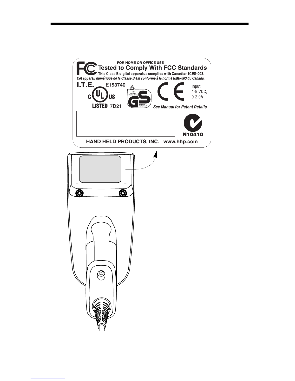
IT4410 Imager Identification
Model # - 4410XX-XX
Manufactured - August 2002
Serial # = P-12-34567
S/W = 34567001/4410
Enlarged View of Label
1 - 4
Hand Held IT4410 Imager
Bottom View
Page 17
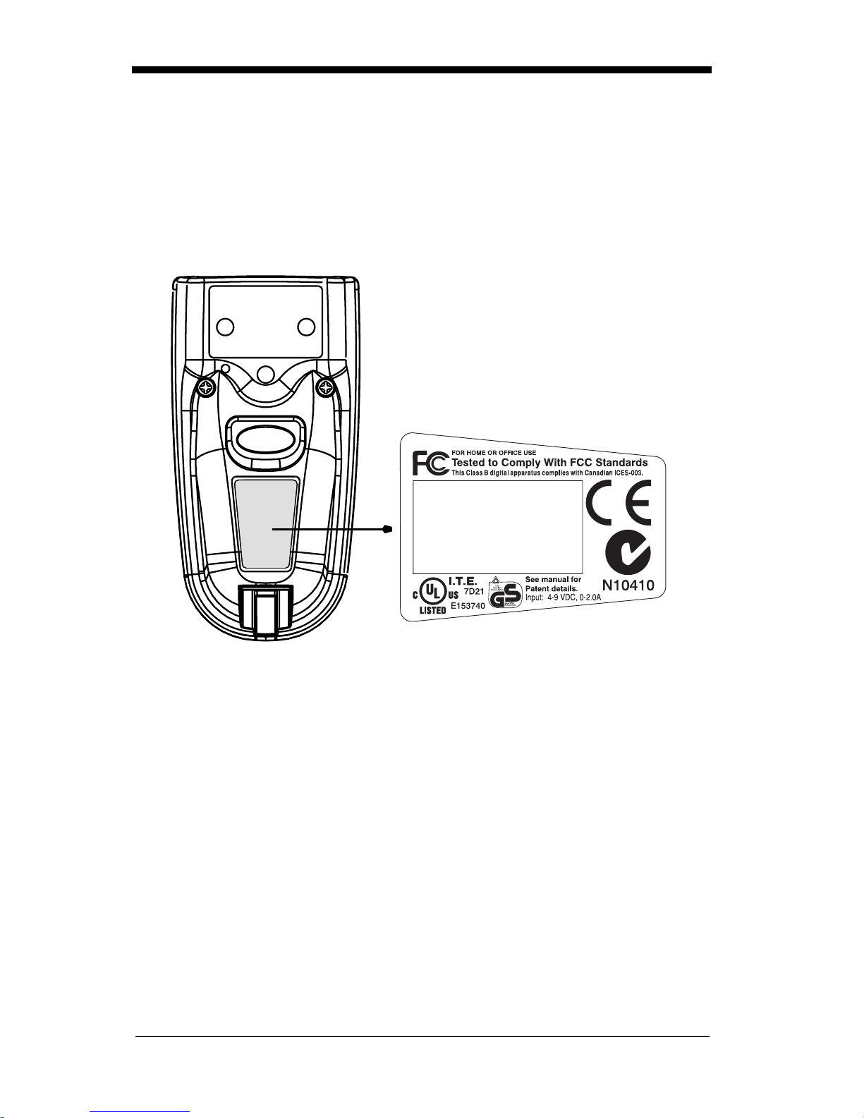
IT4710 Imager Identification
ITEM # IT4710
DATE / SN:
S / W Rev:
HHP, Skaneateles Falls
NEW YORK 13153
Hand Held IT4710 Imager
Bottom View
1 - 5
Page 18
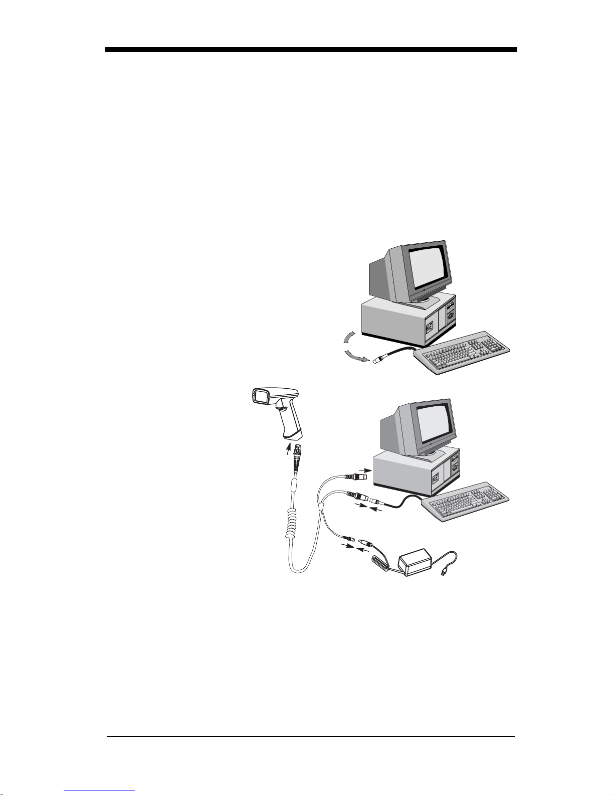
Connecting the Scanner in Keyboard Wedge Mode
A scanner can be connected between the keyboard and PC as a “keyboard
wedge,” plugged into the serial port, or connected to a porta ble data termin al in
non decoded output mo de.
Note: The IMAGETEAM 4410 and 4710 scanners are fac tory programmed for a
keyboard wedge interface to an IBM PC AT with a USA keyboard.
The following is an example of a keyboard wedge connection:
1. Turn off power to the terminal/computer.
2. Disconnect the keyboard cable from
the back of the terminal/computer.
Disconnect
3. Connect the appropriate interface cable to
the scanner and to the
terminal/
computer. The scanner will beep twice.
4. Connect the power
1
supply (4 to 9V).
3
5. Turn the terminal/computer power back on.
6. Verify the scanner
2
operation by sc anning
a bar code. The scanner will beep once.
4
The scanner is now co nnected and ready to communi cate with your terminal/PC.
You must program the scanner for your interface before bar code data can be
transmitted to your terminal/PC. If you are using the scanner as a keyboard
wedge, see"Terminal Interface" on page 2-4. If the scanner is connected via a
serial port, turn to "Connecting the Scanner to a Serial Port" on page 1-7.
1 - 6
Page 19

Connecting the Scanner to a Serial Port
Turn off power to the terminal/computer.
1. Connect the interface cable to the scann er
2. Connect the interface cable to the 4 to 9 volt power supply and plug in the
power supply. The scanner will beep twice.
3. Connect the interface cable to the terminal/c om pu ter.
2
Power Supply
3
Interface Cable
1
4. Turn the terminal/computer power back on.
5. Verify the scanner operation by scanning a bar code from the sample bar
code section in the back of this manual. The scanner will beep once.
The scanner is now co nnected and ready to communi cate with your terminal/PC.
Turn to "Communi cation Settings" on page 2-10 to pr ogra m th e co mm un ic ati on
parameters for a serial interface.
1 - 7
Page 20
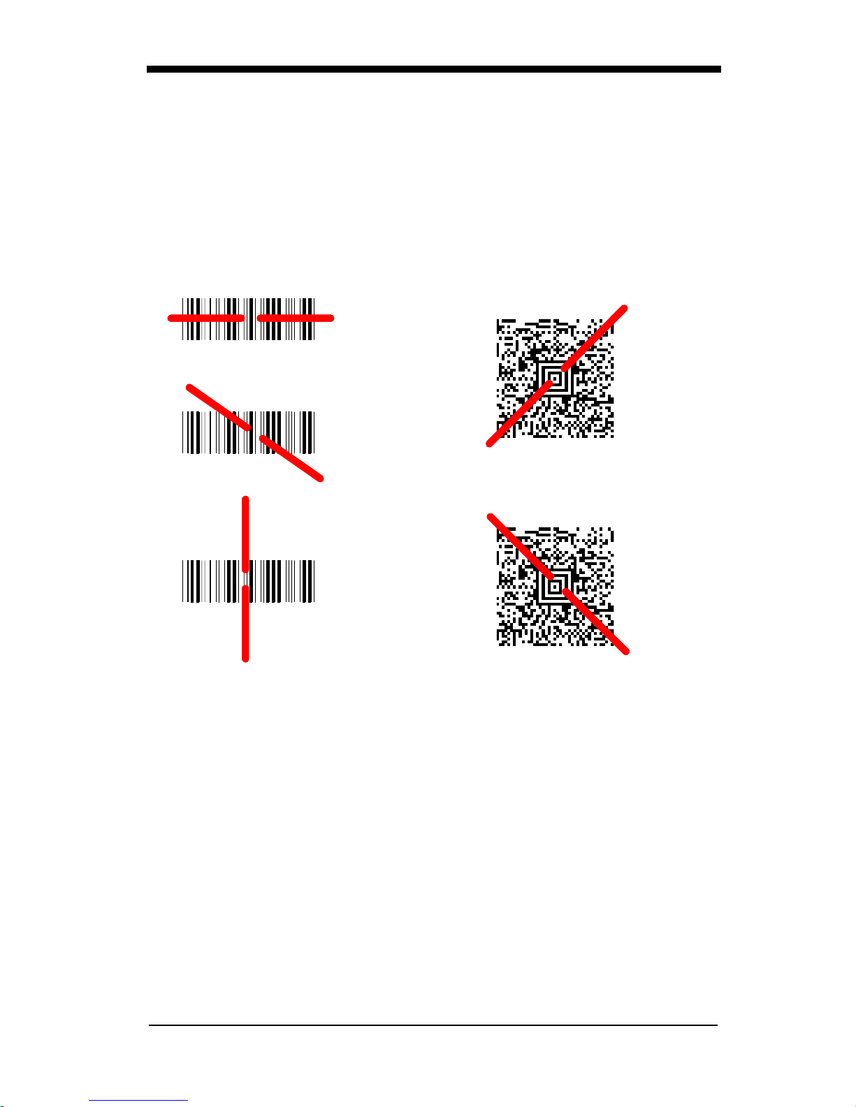
Reading Techniques
The hand-held Imager has a view finder that projects a bright red aiming beam
that corresponds to the Imager’s horizontal field of view. The aiming beam
should be cent ered over the bar code, bu t it can be position ed in any direction for
a good read.
Linear bar code 2D Matrix symbol
The aiming beam is smaller when the Imager is closer to the code and larger
when it is farth er from the code. Sym bologie s with sma ller bars or e lements (mil
size) should be rea d closer to the unit. Symbol ogies with larger bars or elements
(mil size) should be read farther from the uni t. (see "Depth of Field Cha rts (4410
& 4710)" on page 10-4.) To r ead s ingle or mu ltiple sym bols (on a page or on an
object), hold the Imager at an appropriate distance from the target, pull the
trigger, and center the aiming beam on the symbol.
1 - 8
Page 21

2
Programming
Introduction
Use this section to program the hand-held or fixed mount Imager.
This programming section contains the following menuing selections:
• General Selections
• Terminal Interf ace Select ions
• Keyboard Selections
• Communication Settings
• Imager Selections
• Output Selections
• Prefix/Suffix Selections
• Data Formatter Selections
• Output Sequence Sele cti ons
2 - 1
Page 22

Reset Factory Settings
All operating parameters are stored in nonvolatile memory resident in the
Imager, wher e they are permanently re tained in the event of a power interruption.
When you receive your Imag er, certain operating param eters have already been
set. These are the factory defaults, indicated by the symbol “✱” on the
programming menu pages (beneath the default programming symbol). Default
charts begin on page 5-1.
Default
Status Check
Read the
level to the host terminal. The software revision will be printed out as
“REV_SW:$ProjectRevision:1.xx$;REV_WA:31204960-xxx.”
Read the
Editor formats. One format per line will be printed out.
Show Software
Show Software Revision
Show Data Formats
Revision
symbol to transmit the software revision
symbol to transmit the existing Data Format
Show Data Formats
All Symbologies
If you want to decode all the symbologies allowable for your scanner, scan the
All Symbologies On
code.
All Symbologies
On
2 - 2
All Symbologies
Off
Page 23

Revision Selections
Both the follo wing programm ing codes woul d not normally be needed unl ess you
have a problem with the unit. An Application Support Representative may
request the boot c ode or powe r PC revisi on in format ion i n orde r to tro uble shoot
a problem.
Boot Code RevisionPower PC Revision
2 - 3
Page 24

Terminal Interface
IMAGETEAM 4410 and IMAGETEAM 4710 scanners are factory programmed
for a keyboard wedge interface to an IBM PC AT with a USA keyboard. If this is
your interface and you do not need to modify t he setting s, skip to "Po wer Saving
Mode" on page 2-16 to begin programming the scanner.
If your interface is not a standard PC AT, refer to the "Supported Terminals
Chart" on page 2-5 and locate the Terminal ID number for your PC. Scan the
Terminal ID bar code below, then scan the numeric bar code(s) on the inside
back cover of this manual to program the scanner for your terminal ID> Scan
Save to save your selection.
For example, an IBM PS/2 terminal has a Terminal ID of 002. You would scan
the Termin al ID b ar code, th en 0, 0, 2 from the insi de bac k cover, th en Save. If
you make an error while scanning the digits (before scanning Save), scan the
Discard code on the back cover and scan the digits and the Save code again.
Note: Factory Default for Keyboard Wedge units = 003
Note: Factory Default for True RS-232 units = 000
Terminal ID Save
2 - 4
Page 25

Supported Terminals Chart
Terminal Model(s)
DEC PC433 SE (Portable PC) 003
DELL Latitude (Portable PC) 003
DTK 486 SLC (Portable PC) 003
Fujitsu Stylistic (Portable PC) 003
HHLC (Code 128 Emulation) 089
IBM PC XT 001
IBM PS/2 25, 30, 77DX2 002
IBM
IBM
IBM
IBM
IBM AT Thinkpad 106
Midwest Micro Elite TS 30 PS (Porta ble PC) 003
AT, PS/2 30-286, 50, 55SX, 60, 70,
70-061, 70-121, 80
AT Compatibles Keyboard Emulation
(Non-wedge)
Thinkpad 360 CSE, 34, 750
(Portable PC)
Thinkpad 365, 755 CV
(Portable PC)
Terminal
I.D.
003
003
097
003
Mitak 4022 (Portable PC) 003
Olivetti M19, M24, M28, M200 001
Olivetti M240, M250, M290, M380, P500 003
Reliasys TR 175 003
RS-232 TTL 000
Televideo 990, 995, 9060 002
Texas Instruments Extensa 560CD (Portable PC) 003
Toshiba 2600 (Portable PC) 003
Toshiba Satellite T1960, T2130, CS (Portable PC) 003
Zenith Z-note (Portable PC) 003
2 - 5
Page 26

Keyboard Country
Scan the Program Keyboard Country bar code below, then scan the numeric
bar code(s) from the inside back cover, then the Save bar code to program the
keyboard for your country. As a general rule, the following characters are not
supported by the scanner for cou ntri es othe r than the U nite d States:
@ | $ # { } [ ] = / ‘ \ < > ~
Keyboard Country
Country Code Scan Country Code Scan
Belgium..................... 1 Latin America.........14
Czechoslovakia........ 15 Norway...................9
Denmark...................8 Poland....................20
Finland...................... 2 Portugal .................13
France ...................... 3 Romania ................25
French Canadian...... 18 Russia....................26
Germany/Austria.......4 Slovakia.................22
Great Britain ............. 7 Spain......................10
Greece...................... 17 Sweden..................23
Netherlands.............. 11 Switzerland............6
Hungary.................... 19 Turkey Q................24
Israel......................... 12 Turkey F.................27
Italy........................... 5 USA
(Default)
.........0
2 - 6
Save
Page 27

Keyboard Style
This programs keyboard styles, such as Caps Lock and Shift Lock.
Default =
Regular.
Regular
Caps Lock
Shift Lock
to U.S. keyboards.)
Automatic Caps Lock
software trac ks and reflects i f you ha ve Caps Loc k on or off (AT and PS/2 only ).
This selecti on can o nly be u sed with s ystem s that h ave an L ED whic h notes the
Caps Lock status.
is used when you normally have the Caps Lock key off.
is used when you normally have the Caps Lock key on.
is used when y ou normally have the Sh ift Lock ke y on. (Not c ommon
is used if you change the Caps Lock key on and off. The
* Regular
Caps Lock
Shift Lock
Emulate External Keyboard
keyboard (IBM AT or equivalent). To connect to a laptop, you must scan the
Emulate External Keyboard bar code below, then scan "Automatic Direct
Connect Mo de On " on page 2-8 . After scanning th es e c ode s, you must re-boot
your laptop.
should be s c ann ed if you do not have an ex ternal
Emulate External
Keyboard
Automatic
Caps Lock
2 - 7
Page 28

Keyboard Modifiers
This modifi es special ke yboard features, such as CTR L+ ASCII codes and Turbo
Mode.
Control + ASCII Mode On
control characters for values 00-1F. Refer to "Keyboard Function
Relationships" on page 2-9 for CTRL+ ASCII Values.
Control + ASCII
Mode On
Turbo Mode
use with IBM AT only.) If the term inal drops cha racters, do not use Turbo Mode.
- The scanner send s charac ters to an IBM AT termi nal faster . (For
- The scanner sends key combinations for ASCII
Default = Off
* Control + ASCII
Mode Off
Default = Off
Turbo Mode On
Numeric Keypad Mode
numeric keypad.
Default = Off
- Sends numeric characters as if entered from a
Turbo Mode Off
*
Numeric Ke ypad
Mode On
Automatic Direct Connect
keyboard is disabled when you plug in the scanner. This selection can also be
used if you have an IBM AT styl e terminal and th e system is droppi ng characters.
After scanning these codes, you must re-boot your computer.
Automatic Direct
Connect Mode On
2 - 8
* Numeric
Keypad Mode Off
- Use this se lec tion if you are us in g a la ptop whose
Default = Off
* Automatic Direct
Connect Mode Off
Page 29

Keyboard Function Relationships
The following Keyboard Function Code, Hex/ASCII Value, and Full ASCII
“CTRL”+ relationships apply to all terminals that can be used with the scanner.
Function Code HEX/ASCII Value Full ASCII “CTRL” +
NUL 00 2
SOH 01 A
STX 02 B
ETX 03 C
EOT 04 D
ENQ 05 E
ACK 06 F
BEL 07 G
BS 08 H
HT 09 I
LF 0A J
VT 0B K
FF 0C L
CR 0D M
SO 0E N
SI 0F O
DLE 10 P
DC1 11 Q
DC2 12 R
DC3 13 S
DC4 14 T
NAK 15 U
SYN 16 V
ETB 17 W
CAN 18 X
EM 19 Y
SUB 1A Z
ESC 1B [
FS 1C \
GS 1D ]
RS 1E 6
US 1F -
2 - 9
Page 30

Communication Settings
<Default All RS-232 Communication Settings>
Parity
Parity provides a means of checking character bit patterns for validity. The
Imager can be configured to operate under
(
the Imager, to ensure reliab le com m uni ca tio n.
) parity options. The host terminal must be set up for the same parity as
None
Mark, Space, Odd, Even
, or No
SpaceMark
Odd
2 - 10
Even
* None
Page 31

Baud Rate
This sets the baud rate from 300 bits p er second to 11 5,200 bits per second ( see
next page). Pr ogra mm in g b aud rat e c aus es th e d ata to be se nt a t th e s pe cified
rate. The host terminal must be set to the same baud rate as the Imager to
ensure reliable communication.
300 600
1200
19200
2400
96004800
* 38400
2 - 11
Page 32

Baud Rate,
57600 115200
continued
Word Length Data Bits
You can set the W ord Length at 7 or 8 bi ts of data per character. If an a pplication
requires only ASCII Hex characters 0 through 7F decimal (text, digits, and
punctuation), select 7 data bits. For applications requiring use of the full ASCII
set, select 8 data bits per character.
7 Data Bits
Word Length Stop Bits
Word Length can be set to one or two stop bits.
* 1 Stop Bit
* 8 Data Bits
2 Stop Bits
2 - 12
Page 33

Hardware Flow Control
When hardware flo w con trol is On, the software chec ks for a CTS signal before
sending data. This option is useful when your application supports the CTS
signal.
On
* Off
Software Flow Control
This allows control of data transmission from the Imager using software
commands from the host device. When this feature is turned
control is used. When Data Flow Control is turned On, the host dev ice suspends
transmission by sending the XOFF character (DC3, hex 13) to the Imager. To
resume transmission, the host sends the XON character (DC1, hex 11). Data
transmission continues where it left off when XOFF was sent.
On
, no data flow
Off
* Off
2 - 13
Page 34

Serial Triggering
This provides a means of sending a serial trigger command to start and stop
decoding. When this feature is turned
trigger commands. When serial triggering is turned On, the Imager requires a
serial trigger ch aracter to activate sc anning and dec oding. The unit co ntinues to
scan and dec ode until the
occurs, or a bar code is decoded.
On the "Decimal to Hex to ASCII Conversion Chart" on page 2-36, find the hex
characters you want to use to turn the trigger on and off. Locate the decimal
values for those characters and scan the 2 digits for each one from the
Programming Chart in the back of this manual.
Trigger Off
When Serial Trigge ring is On, the default Trigge r On decimal charact er is 18 (hex
12, DC2), and the default Trigger Off decimal character is 20 (hex 14, DC4).
, the Imager will not respond to se rial
Off
character turns off the scanner, a time out
* OffOn
Trigger On ‡
Note: ‡ A one to three digit decimal numb er and Save are r equired after rea ding
this programming symbol. See "Decimal to Hex to ASCII Conversion
Chart" on page 2-36, and the Programming Chart (inside back cover).
2 - 14
Trigger Off ‡
* Trigger Defaults
Page 35

Trigger Timeout
Use this selection to set a timeout (in quarter seconds) of the Imager’s trigger.
Once the imager has timed out, it must be triggered again either serially (see
"Serial Triggerin g" on page 2-14), or manua lly. Set the Trigger Ti meout to 00 if
you don’t want a Trigger Timeout.
Note: ‡ A one- to three digit number and Save are required after reading this
programming symbol. Refer to the Programming Chart (inside back
cover).
Default setting = 120 seconds
Set Timeout ‡
2 - 15
Page 36

Power Saving Mode
This provides control of the Imager’s power consumption, as follows:
Low Power
read attempt
movement durin g the rea d attempt , an d powe rs down aft er t he image capt ure is
complete.
Medium Powe r
enhances motion tolerance.
trigger is pulle d, going into a “doze” (low power) st ate after each read attempt.
The Imager powers down ten seconds after the image capture is complete.
Normal Power
trigger is pulled or a decode is in process. The Imager doesn’t go into a “doze”
state after each read attempt, but will power down after two minutes if Power
Hold Mode is turned Off .
Low Power Medium Power
draws low (50%) LED current during image capture, allowing one
only
for each trigger pull. The Imager is less tolerant of hand
draws a normal LED current during image capture which
Medium Power
draws a normal LED current, attempting to read as long as the
attempts to read as long as the
2 - 16
* Normal Power
Page 37

Power Hold Mode
Power Hold On keeps the Imager in a read y to read s tate . To con se rve pow er,
this sel ection may be turned
two minutes. When you are ready to use the Imager again, restore power by
pressing the trigger.
On * Off
and the unit will power down if not used within
Off
LED Power Level
This selection allows you to adjust LED brightness.
is used when no illumination is needed.
Off
sufficient.
Off
(the default) is the brightest setting.
High
* High
is used if low illumination is
Low
Low
2 - 17
Page 38

LED Flashing
When LED Flashing is On, the LEDs and aiming light alternately flash until a
symbol is decoded or the trigger is released.
If LED Flashing is turned
aiming light won’t illuminate while the scanner reads a bar code. The LEDs
remain on while the scanner is reading.
Off * On
, the average current draw is increased and the
Off
Aimer Delay
The aimer delay allows a delay time for the operator to aim the scanner before
the picture is taken. Use these codes to set the time between when the trigger
is pulled and when the picture is taken. During the delay time, the aiming light
will appear, but the LEDs won’t turn on until the delay time is over.
200 milliseconds
400 milliseconds
2 - 18
* Off
(no delay)
Page 39

Aimer Interval
Aimer Interval turns off the aiming light, or programs the aimer to come on at
certain interv als when rea din g sy mbols w ith the sc anner. You m ay p rogr am the
scanner to use the aimer
. You may also program the scanner to use the aimer every “x” reads, by
Read
entering a number from 0 to 999 to indicate “x.”
Every Read, Every Second Read
, or
Every Third
* Every ReadOff
Every Second Read
Every “x” Reads
‡
Every Third Read
Note: ‡ A one- to three digit number and Save are required after reading this
programming symbol. Refer to the Programming Chart (inside back
cover).
2 - 19
Page 40

Centering
Use the centering feature to narrow the imager’s field of view to ma ke su re that
the imager reads only those bar codes intended by the user. For instance, if
multiple codes are placed closely together, centering will insure that only the
desired codes are read. When centering is turned on, the imager only reads
codes that intersect the centering window set up by the user. The centering
window must intersect the center of the image. If a bar code is not within the
predefined window, it will not be decoded or output by the scanner.
If centering is turned on by scanning th e On bar code below, th e default centering
window is a 60 pixel squ are area in th e center of the imager’ s field of view . The
position of the window may be changed by scanning the top, bottom, left, and
right centering bar codes tha t follow and the appropriate pixel value, if other than
the default, fro m the Programming C hart in the back of this manual. Th e defaults
are listed in the table below.
Window Position Default Minimum Maximum Serial Command
Top of centering
window
Bottom of centering window
Left of centering
window
Right of centering
window
210 000 239 DECTPYxxx
270 240 479 DECBTYxxx
290 0 319 DECTPXxxx
350 320 639 DECBTXxxx
The centering function can be used in conjunction with the Aimer Delay feature
(page 2-18) for the most error-free operation in applications where multiple
codes are spaced closely together. Using the Aimer Delay and Centering
features, the i ma ger c an em ula te the operation of ol der systems, such as l ine ar
laser bar code scanners.
* OffOn
2 - 20
Page 41

The figure belo w illustrates th e default top, b ottom, left, an d right pixel pos itions.
The position of the pixels is measured from the top and the left side of the
imager’s field of view with the field of view being 640 by 480 pixels.
290 350
0
640
Top
210
270
480
Left
Right
Bottom
Default
Center
2 - 21
Page 42

Top of Centering
Window
Top of Centering Window
Default (210)
Bottom of Center ing
Window
Left of Centering
Window
Bottom of Centering
Window Default (270)
Left of Centering
Window Default (290)
Right of Centering
Window
2 - 22
Right of Centering
Window Default (350)
Page 43

In the example bel ow, the gray area is the full imag er field of view and the white
area is the centering window. Bar Code 1 will not be read, while Bar Co de 2 will
be.
Bar Code 1
Bar Code 2
AutoTrigger
Two AutoTrigger Modes are available: Scan Stand and Presentation Mode.
When a unit is in Scan Stand mode, it remains idle as long as it sees the Scan
Stand symbol. (See Sc an Stan d Sym bol th at foll ows.) When a diffe rent co de is
presented, the Imager is triggered to read the new code.
Note: The scanner a utomatically adjusts the illu mination LEDs to the lowest light
level possible to mai nta in a good loc k on the Sca n Stand sy mb ol.
Presentatio n mode is for those app lications where a sc an stand will not w ork, i.e.,
when large packages m ust be scanned. To p rogram the device for pre sentation
mode, refer to "Presentation Mode" on page 2-24.
2 - 23
Page 44

Scan Stand
This selection programs the Imager to work in a Scan Stand.
On* Off
Scan Stand Symbol
Note: Scan Stand mode does not work when scanner is programmed for the
HHLC interface.
When a unit is in Scan Stand mode, the LEDs shine at the Scan Stand symbol
on the base of the stand which tells it to remain idle. When the Scan Stand
symbol is covered, the imager turns the LEDs on at the configured power level
(Default High) and attempts to find and decode bar codes in its field of view.
Scan Stand
Symbol
Presentation Mode
Note: Presentation Mode does not work when scanner is programmed for the
HHLC interface.
This programs the scanner to work in Presentation Mode.
On* Off
Presentation Re-trigger Delay
This sets the time period before the scanner can re-trigger for another read
attempt. Setting a re-trigger delay protects against accidental rereads of the
same bar code. Longer de lays are ef fective in mi nimiz ing acc ident al rereads at
POS (point of sale ). Use shorter delays in applications w here repetitive ba r code
2 - 24
Page 45

scanning is required. Entries are in milliseconds, from 1 to 10,000. Scan the
Presentation Re-trigger Delay bar code below, then scan the number of
milliseconds and the Save bar code from the inside back cover.
Default = 200.
Presentation Re-trigger Delay
Presentation Lights
When using the scanner in presentation mode, the illuminating LEDs can be
programmed on or off . If there is sufficient ambien t light, the LEDs can be turned
off by scanning the Li ghts O ff bar c ode be low. Whe n a bar code i s pres ented t o
the scanner, th e illumi nating LEDs turn on to sc an the bar cod e and then t urn off
when the bar code has been read.
Default = Presentation Mode Lights On
.
* On
Presentation Default
Defaults all presentation mode settings.
Presentation Reread Delay 200 ms.
Presentation Defaul t
Defaults
Off
=
Presentation Mode Off,
2 - 25
Page 46

Fast Omni Mode
Normally, the imager searches throughout its whole field of view to determine if
a bar code is present. Fast omni-directional mode provides a reduced search
pattern that increases the scan rate of the imager. When fast omni mode is
enabled, the imager only tries to locate bar codes in the center are a of the image.
Consequently , the user is requir ed to center the aimin g line over the bar c ode he
wants to read. When a portion of the ba r code i s in the center area of th e image,
the imager lo cates and decodes the bar code. The e ntire bar code does n ot need
to be in the c ente r a rea, on ly a portion of it. Bar co des that are not in the center
area of the image will not be found.
Note: Fast Omni Mod e is no t recomm ended w hen sc anning Data Matrix codes .
* Normal, Full
Search Mode
Beeper Volume
Off
Medium
Reduced Omni-
directional Mode
Low
* High
2 - 26
Page 47

Power Up Beeper
* On
Off
Output Sequence Beeper
If you are using an Output Sequenc e (see "Output Sequen ce Overview" on page
2-43), you may want to hear a beep after each bar code as it is read. Scan
Output Sequence Beeper On to enable this feature, or
* On
to disable it.
Off
Off
Beep On Decode
If you want th e s canner to beep each ti me it reads a bar c ode , l eav e this s ett ing
. If you don’t want it to beep on each read, but do want it to beep for other
On
events, such as error conditions, set this selection to
Off
.
* On
Beeper Default
Defaults all beep er setting s.
On, Output Sequence Beeper On, Beep On Read On.
Defaults
=
Beeper Default
Off
Beeper Volume High , Power Up Beep er
2 - 27
Page 48

Intercharacter, Interfunction,
and Intermessage Delays
Some terminal s drop inform ation (chara cters) if data comes through too quickl y.
Intercharacter, interfunction, and intermessage delays slow the transmission of
data increasing data integrity.
Each delay is composed of a 5 millisecond step. You can program up to 99 steps
(of 5 ms each).
Intercharacter Delay
Note: This selection is valid for keyboard wedge interfaces only.
This is a delay of up to 495 milliseconds (in multiples of 5) placed between the
transmission o f each character o f scanned data. Yo u can program up to 99 steps
(of 5 ms each). Scan the
number of steps, and the
Intercharacter Delay
bar code from the inside back cover.
Save
bar code below, then scan the
Note:
To remove this delay, scan the
number of steps to 00 . Scan the
If you make an error while scanning the digits (before scanning Save),
scan
again.
Discard
on the back cover and scan the correct digits and
Prefix Scanned Data Suffix
1 2345
Intercharacter Delay
Intercharacter Delay
Intercharacter Delay
bar code from the inside back cover.
Save
User Specified Intercharacter Delay
Save
bar code, then set the
Note: This selection is valid for keyboard wedge interfaces only.
This is a delay of up to 495 milliseconds (in multiples of 5) placed after the
transmission of a particular character of scanned data. You can program up to
99 steps (of 5 ms each) to follow the character you specify. Scan the
Length
Save
bar code below, then scan the number of steps for the delay, and the
bar code from the inside back cover.
2 - 28
Delay
Page 49

Next, scan t he
ASCII character that trigger the delay (refer to the "Decimal to Hex to
ASCII Conversion Chart" on page 2-36).
scanning the digits (before scanning Save), scan
cover and scan the correct digits and
Character to Trigger
bar code, then the 2 digit hex va lue for th e
Note:
If you make an error while
on the back
Save
Discard
again.
Delay Length
To remove this delay, scan the
steps to 00. Scan the
bar code from the inside back cover.
Save
Delay Length
Character to Trigger Delay
bar code, then set the numbe r of
Interfunction Delay
Note: This selection is valid for keyboard wedge interfaces only.
This is a delay of up to 495 milliseconds (in multiples of 5) placed between the
transmissio n of e ach s egmen t of the mess age s tring. You can progra m up t o 99
steps (of 5 m s eac h). Scan the
the number of steps, and the
Interfunction Delay
bar code from the inside back cover.
Save
Note: If you make an error while scanning the digits (before scanning Save),
scan Discard on the back cover and scan the correct digits and Save
again.
Prefix Scanned Data Suffix
1 2345STX HT CR LF
bar code below, then sc an
To remove this delay, scan the
number of steps to 00 . Scan the
Intermessage Delay
Note: This selection is valid for keyboard wedge interfaces only.
Interfunction Delays
Interfunction Delay
Interfunction Delay
bar code from the inside back cover.
Save
bar code, then set the
2 - 29
Page 50

This is a de lay o f up to 495 m illis econd s (in m ultip les o f 5) pla ced b etwee n each
scan transmission. You can program up to 99 steps (of 5 ms each). Scan the
Intermessage Delay
bar code from the inside back cover.
Save
bar code below, then scan the number of steps, and the
Note:
If you make an error while scanning the digits (before scanning Save),
scan
Discard
on the back cover and scan the correct digits and
again.
Intermessage Dela y
Intermessage Delay
To remove this delay, scan the
Intermessage Delay
number of steps to 00 . Scan the
2nd Scan Transmission1st Scan Transmission
bar code, then set the
bar code from the inside back cover.
Save
Save
2 - 30
Page 51

Prefix/Suffix Overview
When a bar code is sca nned, additi onal informati on is sent to the ho st compute r
along with the bar code data. This group of bar code data and additional,
user-defined d ata is called a “m essage strin g.” The selec tions in this section are
used to build the user-defined data into the message string.
Prefix and Suffix cha racters are data characters that ca n be sent before and after
scanned data. You can specify if they should be sent with all symbologies, or
only with specific symbologies. The following illustration shows the breakdown
of a message string:
Prefix Scanned Data Suffix
1-10
alpha
numeric
characters
variable
length
1-10
alpha
numeric
characters
Points to Keep In Mind
• It is not necessary to build a message string. The selections in this
chapter are only used if you wish to alter the default settings.
prefix = None. Default suffix = CR/LF
• A prefix or suffix may be added or cleared from one symbology or all
symbologies.
• You can add any prefix or suffix from the "Decimal to Hex to ASCII
Conversion Chart" on page 2-36, plus Code I.D. and Aim I.D.
• You can string together several entries for several symbologies at one
time.
• Enter prefixes and s uffixes in the order in whic h you want them to appea r
on the output.
.
Default
2 - 31
Page 52

Adding a Prefix or Suffix
1. Scan the
2. Determine the 2 digit Hex value from the "Symbology Chart" on page 2-35
for the symbology to which you want to apply the prefix or suffix.
3. Scan the 2 hex digits from the Programming Chart inside the back cover or
scan 9, 9 for all symbologies.
4. Determine the hex value from the "Decimal to Hex to ASCII Conversion
Chart" on page 2-36 for the prefix or suffix you wish to enter.
5. Scan the 2 digit hex value from the Programming Chart inside the back
cover.
Note:
Note:
6. Scan Save to exit and save, or scan Discard to exit without saving.
Repeat Steps 1-6 to add a prefix or suffix for another symbology.
Example: Add a Suffix to a specific symbology
To send a CR (carriage return)Suffix for UPC only:
1. Scan
Repeat Steps 4 and 5 for every prefix or suffix character.
To add the Code I.D., scan
To add AIM I.D., scan
To add a backslash (\), scan
Add Prefix
Add Suffix
(page 2-34) or
5, C, 8, 1
.
Add Suffix
5, C, 8, 0
.
5, C, 5, C.
symbol (page 2-34).
.
2. Determine the 2 digit hex value fro m the "S ymbology C hart" on page 2-35 for
UPC.
3. Scan
4. Determine the hex value from the "Decimal to Hex to ASCII Conversion
Chart" on page 2-36 for the CR (carriage return).
5. Scan
6. Scan
from the Programming Chart (inside back cover ).
6, 3
from the Programming Chart (inside back cover).
0, D
Save
, or scan
Discard
to exit without saving.
Clearing One or All Prefixes or Suffixes
You can clear a single prefix or suffix, or clear all prefixes/suffixes for a
symbology. When you Clear One Prefix (Suffix), the specific character you
select is deleted from the symbology you want. When you Clear All Prefixes
(Suffixes), all the prefixes or suffixes for a symbology are deleted.
1. Scan the
2. Determine the 2 digit Hex value from the "Symbology Chart" on page 2-35
for the symbology from which you want to clear the prefix or suffix.
3. Scan the 2 digit hex value from the Programming Chart inside the back cover
or scan
Your change is automatically saved.
Clear One Prefix
for all symbologies.
9, 9
symbol.
2 - 32
Page 53

Add a Carriage Return Suffix to All Symbologies
Scan the followi ng bar code if you wish to add a Carriage Return /Line Feed Suffix
to all symbologies at once. This action first clears all current suffixes, then
programs a carriage return suffix for all symbologies.
Add CR/LF Suffix
All Symbologies
Add a Code I.D. Prefix to All Symbologies
This selection allows you to turn on (or off) transmis sion of a Code I.D. b efore the
decoded symbology. (See the "Symbology Chart" on page 2-35 for the single
character code that identifies each symbol ogy.) This action first clears al l current
prefixes, then programs a Code I.D. prefix fo r all symbologies.
Add Code ID Prefix
All Symbologies
Add an AIM I.D. Prefix to All Symbologies
This selecti on allows you to turn on (or off) transmissi on of an AIM I.D. before the
decoded symbology. (See the "Symbology Chart" on page 2-35 for the single
character code that identifies each symbol ogy.) This action first clears al l current
prefixes, then programs an AIM I.D. prefix for all symbologies.
Add AIM ID Prefix
All Symbologies
(See AIM Guidelines on Symbology Identifiers for more information on the AIM
symbology ID characters.)
2 - 33
Page 54

Prefix Entries
Add Prefix †
Suffix Entries
Add Suffix †
Clear One P refix †
Clear All Prefixes
Clear One
Suffix †
† One or more two digit numbers and
programming symbol. Refer to the Programming Chart (inside back cover).
Exit Selections
Save Discard
2 - 34
Clear All Suffixes
are required after reading this
Save
Page 55

Symbology Chart
Symbology
Australian 4 State
Aztec Code
BC412**
BPO 4 State
Canadian 4 State
Codabar
Codablock-F
Code 11
Code 39
Code 49
Code 93
Code 128
Code Z**
Data Matrix
EAN
IATA 2 of 5
CodeIDAIMIDHex
ID
A]X41
z]z7A
g]X67
B]X42
C]X43
a]F61
q]O71
h]H068
b]A62
l]T6C
i]G69
j]C6A
u]X75
w]d77
d]E64
f]R66
Symbology
Interleaved 2 of 5
Japanese Postal
Kix (Dutch) Postal
Maxicode
Micro PDF417
MSI
No Read
OCR
PDF417
Planet Code
Postnet
QR Code
RSS/Composites
UPC
Vericode**
All Symbologies
CodeIDAIMIDHex
e]l65
J]X4A
K]X4B
x]U78
R]L52
g]M067
o]Y6F
r]L72
L]X4C
P]X50
s]Q73
y]e79
c]E63
v]V76
†
ID
9C
99
Note: Prefix/Suffix entries for specific symbologies override the universal (All
Symbologies, 99) entr y.
Note:† All Symbologies: Prefix/Suffix programming only!
Note: ** Not available in standard product. Only available when ordered in
custom firmware
2 - 35
Page 56

Decimal to Hex to ASCII Conversion Chart
Dec. Hex ASCII Dec. Hex ASCII Dec. Hex ASCII Dec. Hex ASCII
0 00 NUL 32 20 SP 64 40 @ 96 60 ‘
1 01 SOH 33 21 ! 65 41 A 97 61 a
2 02 STX 34 22 “ 66 42 B 98 62 b
3 03 ETX 35 23 # 67 43 C 99 63 c
4 04EOT3624$ 6844D 10064d
5 05ENQ3725% 6945E 10165e
6 06ACK3826& 7046F 10266f
7 07BEL3927‘ 7147G 10367g
8 08BS 4028( 7248H 10468h
9 09HT 4129) 7349l 10569i
10 0A LF 42 2A * 74 4A J 106 6A j
11 0B VT 43 2B + 75 4B K 107 6B k
12 0C FF 44 2C , 76 4C L 108 6C l
13 0D CR 45 2D - 77 4D M 109 6D m
14 0E SO 46 2E . 78 4E N 110 6E n
15 0F SI 47 2F / 79 4F O 111 6F o
16 10 DLE 48 30 0 80 50 P 112 70 p
17 11 DC1 49 31 1 81 51 Q 113 71 q
18 12 DC2 50 32 2 82 52 R 114 72 r
19 13 DC3 51 33 3 83 53 S 115 73 s
20 14 DC4 52 34 4 84 54 T 116 74 t
21 15 NAK 53 35 5 85 55 U 117 75 u
22 16 SYN 54 36 6 86 56 V 118 76 v
23 17 ETB 55 37 7 87 57 W 119 77 w
24 18 CAN 56 38 8 88 58 X 120 78 x
25 19 EM 57 39 9 89 59 Y 121 79 y
26 1A SUB 58 3A : 90 5A Z 122 7A z
27 1B ESC 59 3B ; 91 5B [ 123 7B {
28 1C FS 60 3C < 92 5C \ 124 7C |
29 1D GS 61 3D = 93 5D ] 125 7D }
30 1E RS 62 3E > 94 5E ^ 126 7E ~
31 1F US 63 3F ? 95 5F _ 127 7F DEL
2 - 36
Page 57

Data Format Editor Overview
The Data Format Editor sel ections are used to edit scanned da ta. For example,
you can use the Data Format Editor to insert characters at certain points in bar
code data as it is scanned.
It is not necessary to use the Data Format Editor. A set of defaults for the data
format is already programmed in the scanner. The selections in the following
pages are used onl y if you wish to alter the defau lt settings.
setting = none.
If you have c hanged data format s ettings, and w ish to clear all for mats and return
to the defaults, scan the Default Data Format code.
To Add a Data Format
Default Data Format
1. Scan the
2. Primary/Alternate Format
Determine if this will be your primary data format, or one of 3 alternate formats. (Alternate formats allow you “single shot” capability to scan one bar
code using a different data format. After the one bar code has been read,
the scanner reverts to the primary data format. See "Alternate Data
Formats" on page 2-42.) If you ar e programming the primary format, sc an 0.
If you are programming an alternate format, scan
the alternate format you are programming.
3. Terminal Type
Refer to the "Supported Terminals Chart" on page 2-5 and locate the Terminal ID number for your P C. Scan three nu meric ba r codes on the i nside ba ck
cover to program the scanner for your terminal ID (you must enter 3 digits).
For example, scan
Enter Data Format
0 0 3
symbol (page 2-40).
for an AT wedge.
, or 3, depending on
1, 2
Note: The wildcard for all terminal types is 099.
4. Code I.D.
On page 2-35, find the symbology to which you want to apply the data format. Locate th e Hex value fo r tha t symbol ogy a nd sc an the 2 digit hex v alue
from the Programming Chart.
5. Length
Specify what length (up to 9999 characters) of da ta will be acceptab le for this
symbology. Scan the four digit data length from the Programming Chart.
(Note: 50 characters is entered as 0050. 9999 is a universal number, indicating all lengths. )
6. Editor Commands
Refer to the "Format Editor Commands" on page 2-38. Scan the symbols
that represent the command you w an t t o e nter. 94 alphanum eric c ha rac ters
may be entered for each symbology data format.
7. Scan
to save your entries.
Save
2 - 37
Page 58

Other Programming Selections
• Clear One Data Format
This deletes one data format for one symbology. If you are clearing the
primary forma t, sc an 0. If you are cle aring an alternate form at, scan 1, 2,
or 3, depending on the alternate format you are clearing. Scan the
Terminal Type (refer to the "Supported Terminals Chart" on page 2-5),
Code I.D. and the length of the format you want to delete. That length
data format for that symbology is deleted and all other formats are
unaffected.
• Save
This exits, saving any Data Format changes.
• Discard
This exits without saving any Data Format changes.
Format Editor Commands
Send Commands
F1 Send all characters followed by “xx” key or function code, starting from
current cursor position.
ASCII code, see "Decimal to Hex to ASCII Conversion Chart" on page 2-
36.)
F2 Send “nn” characters followed by “xx” key or function code, starting from
current cursor position.
value (00-99) f or the numb er of characters and xx s tands for the h ex value
for an ASCII code. See "Decimal to Hex to ASCII Conversion Chart" on
page 2-36.)
F3 Send up to but not including “ss” character (Search and Send) starting
from current cursor position, leaving cursor pointing to “ss” character
followed by “xx” key or function code.
stand for the hex values for ASCII codes, see "Decimal to Hex to ASCII
Conversion Chart" on page 2-36.)
F4 Send “xx” character “nn” times (Insert) leaving cursor in current cursor
position.
see "Decimal to He x to ASC II Conv ers ion C ha rt" on page 2-36, a nd nn is
the numeric value (00-99) for the number of times it should be sent.)
E9 Send all but the last “nn” characters, starting from the current cursor
position.
of characters that will not be sent at the end of the message.)
Syntax = F4xxnn
Syntax = E9nn
Syntax = F1xx
Syntax = F2nnxx
(xx stands for the hex value for an ASCII code,
(nn is the numeric value (00 -99 ) for the numb er
(xx stands for the he x value for an
(nn stands for the numeric
Syntax = F3ssxx
(ss and xx both
Move Commands
F5 Move the cursor ahead “nn” characters from current cursor position.
Syntax = F5nn
of characters the cursor should be moved ahead.)
F6 Move the cursor back “nn” characters from current cursor position.
Syntax = F6nn
of characters the cursor should be moved back.)
F7 Move the cursor to the beginning of the data string.
EA Move the cursor to the end of the data string.
2 - 38
(nn stands for the numeric value (00-99) for the number
(nn stands for the numeric value (00-99) for the number
Syntax = F7.
Syntax = EA
Page 59

Search Commands
F8 Search ahead for “xx” character from current cursor position, leaving
cursor pointing to “xx” character.
Syntax = F8xx
(xx stands for the hex
value for an ASCII code, see "Decimal to Hex to ASCII Conversion
Chart" on page 2-36.)
F9 Searc h back for “xx ” character from current curso r position, l eaving cursor
pointing to “xx” characte r.
Syntax = F9xx
(xx stands for the hex value for
an ASCII code, see "D ecima l to Hex to ASCII Con versio n Char t" on page
2-36.)
E6 Search ahead for the first non “xx” character from the current cursor
position, leaving cursor pointing to non ”xx” character.
Syntax = E6xx
stands for the hex v alue for an ASCII co de, see "Decim al to Hex to ASCII
Conversion Chart" on page 2-36.)
E7 Search back for the first non “xx” character from the current cursor
position, leaving cursor pointing to non ”xx” character.
Syntax = E7xx
stands for the hex v alue for an ASCII co de, see "Decim al to Hex to ASCII
Conversion Chart" on page 2-36.)
Miscellaneous Comm ands
FB Suppress all occurrences of up to 15 different characters, starting at the
current cursor position, as the cursor is advanced by other commands.
When the FC command is encountered, the suppress function is
terminated. The cursor is not moved by the FB command. Syntax =
FBnnxxyy . .zz w here nn is a cou nt of the n umber suppre ss chara cters in
the list and x xyy .. zz i s the list of cha racters to be suppres sed. (x x st ands
for the hex value for an ASCII code, see "Decimal to Hex to ASCII
Conversion Chart" on page 2-36.)
FC Disable suppres s filter a nd clea r all sup pressed ch aracters.
Syntax = FC.
E4 Replaces up to 15 characters in the data string with user specified
characters. Replacement continues until the E5 command is
encountered.
Syntax = E4nnxx1xx2yy1yy2...zz1zz
where nn is the to tal
2
count of both ch aracters to be replaced p lu s repla ce me nt c hara ct ers ; xx
defines characters to be replaced and xx
characters, continuing through zz
and zz2.
1
E5 Terminates character replacement.
defines replacement
2
Syntax = E5.
FE Compare character in current cursor position to the character “xx.” If
characters are equal, increment cursor. If characters are not equal, no
format match.
Syntax = FExx
(xx stands for the hex value for an ASCII
code, see "Decimal to Hex to ASCII Conversion Chart" on page 2-36.)
EC Check to make sure there is an ASCII number at the current cursor
position. If character is not numeric, format is aborted.
Syntax = EC
ED Ch eck to make sure the re is a non-numeric ASCII ch aracter at the curren t
cursor position. If character is numeric, format is aborted.
Syntax = ED
(xx
(xx
.
1
.
2 - 39
Page 60

Data Format Editor
See page 2-37 throug h page 2-39 for a description of Data Format select ions and
commands.
Enter Data Format † Default
Data Format
(none)
Clear One
Data Format †
Exit Selections
Clear All
Data Formats
Save Current
Data Format Changes
Discard Current
Data Format Changes
† One or more two digit numbers and
programming symbol. Refer to the Programming Chart (inside back cover).
2 - 40
are required after reading this
Save
Page 61

Data Formatter
When Data Formatter is turned off, the bar code data is output to the ho st as read
(including prefixes and suffixes).
* On/Not Required Off
Require Data Format
When Data Formatter is
format or the scanner does not transmit the input data to the host device.
Required
, all input data must conform to an edited
Required
Show Data Formats
Read the
One format per line is printed out.
Show Data Formats
bar code to transmit the existing data formats.
Show Data Formats
2 - 41
Page 62

Alternate Data Formats
Alternate formats allow you “s ingle shot ” capabili ty to scan o ne bar code us ing a
different data format than your primary format. When data formats are
programmed (see page 2-37 ), you mu st input w hether you are program ming the
primary format, or an alternate format numbered 1, 2, or 3.
An alternate format is initiated by scanning one of the 3 alternate format bar
codes below. The s can ne r will s ca n the n ext bar co de, formatting the data with
the selected alternate format, then revert immediately to the primary format.
Alternate
Data Format 1
Alternate
Data Format 2
Alternate Data Format 3
2 - 42
Page 63

Output Sequence Overview
Output Sequence Editor
This programming selection allows you to program the Imager to output data
(when scanning more than one symbol) in whatever order your application
requires, regardless of the order in which the bar codes are scanned. Reading
the
Default Sequence
shown below. Th ese are the defau lts. Be certain you want to delete or clear all
formats before you read the
Note: To make Output Sequ ence Editor selecti ons, you’ll need to kno w the code
I.D., code len gth, and char acter matc h(es) you r applicat ion requires . Use
the Alphanumeric symbols (inside back cover) to read these options.
To Add an Output Sequence
symbol programs the Imager to the Universal values,
Default Sequence
symbol.
1. Scan the
2-46).
2. Code I.D.
On the "Symbology Chart" on page 2-35, find the symbology to whic h you
want to apply the output sequence format. Locate the Hex value for that
symbology and scan the 2 digit hex value from the Programming Chart
(inside back cover).
3. Length
Specify what length (up to 9999 charac ters) of data outp ut will be acceptab le
for this symbology. Scan the four digit data length from the Programming
Chart. (Note: 50 characters is entered as 0050. 9999 is a universal number, ind icating all lengths.)
4. Character Match Sequences
On the "Decimal to Hex to ASCII Conversion Chart" on page 2-36, find the
Hex value that represents the character(s) you want to match. Use the Programming Chart to read the alphanumeric combination that represents the
ASCII characters. (99 is the Universal number, indicating all characters.)
5. End Output Sequence Editor
Scan
Enter Sequence
to enter an Output Sequenc e for an addit ional sy mbol ogy, or
F F
Current Output Sequence Changes
symbol (see "Output Sequence Editor"on page
to save your entries.
Other Prog ramming Selections
•
Discard Current Output Sequence Changes
This exits without saving any Output Sequence changes.
Save
Output Sequence Example
In this exam pl e, y ou are s ca nni ng Code 93, Code 128, an d Cod e 3 9 b ar codes,
but you want the scanner to output Code 39 1st, Code 128 2nd, and Code 93
3rd, as shown below.
2 - 43
Page 64

Note: Code 93 must be enabled to use this example.
A - Code 39
B - Code 128
C - Code 93
You would set up the sequence editor with the following command line:
SEQBLK62999941FF6A999942FF69999943FF
The breakdown of the command line is shown below:
SEQBLKsequence editor start command
62 code identifier for Code 39
9999code length that must match for Code 39, 9999 = all lengths
41 start character match for Code 39, 41h = “A”
FF termination string for first code
6A code identifier for Code 128
9999code length that must match for Code 128, 9999 = all lengths
42 start character match for Code 128, 42h = “B”
FF termination string for second code
69 code identifier for Code 93
9999code length that must match for Code 93, 9999 = all lengths
43 start character match for Code 93, 43h = “C”
FF termination string for third code
2 - 44
Page 65

Require Output Sequence
When an output sequence is
sequence or the scanner will not transmit the output data to the host device.
When it’s
conform to an edi ted s equ en ce, but if it cannot, the scann er tran sm its all outp ut
data to the host device as is.
When the output s eq uen ce is
scanner decodes it.
On/Not Required
Required
, the scanner will attempt to get the output data to
Off
, all output da ta must conform to a n edited
, the bar code data i s o utpu t to the host as the
Note: This selection is unavailable when the Multiple Symbols Selection is
turned on.
Requir ed On/Not Required
Off
2 - 45
Page 66

Output Sequence Editor
Enter Sequence † Default Sequence
Exit Selections
Save Current
Output Sequen ce Changes
Discard Current
Output Sequence Changes
Note: If you want the scanner to beep after each bar code is read, please see
"Output Sequence Beep er" on page 2-27.
† One or more two digit numbers and Save are required after reading this
programming symbol. Refer to the Programming Chart (inside back cover).
2 - 46
Page 67

Multiple Symbols
Note: This feature does not work when the Imager is in Low Power mode.
When this programming selection is turned On, it allows you to read multiple
symbols with a single pull of the Imager’s trigger. If you press and hold the
trigger, aiming the Imager a t a serie s of symb ols, it read s unique s ymbols once,
beeping (if turned on) for each read. Data is output as the imager finds and
decodes the sym bols . Th e ima ger at tempts to find and decod e new sy mbol s as
long as the trigg er is pulle d. When this programming selectio n is turned
Imager will only read the symbol closest to the aiming beam.
Off
, the
On
* Off
No Read
With No Read turned On, the Imager notifies you if a code cannot be read. In
the Quick*View Scan Data Window (see "Scan Data Window" on page 7-4), an
“NR” appears when a code cannot be read. If No Read is turned
will not appear.
On
If you want a different notation than “NR,” for example, “Error,” or “Bad Code,”
you can edi t the output me ssage usin g the Data Formatter (see page 2-37). The
hex code for the No Read symbol is 9C.
, the “NR”
Off
* Off
2 - 47
Page 68

Print Weight
Print Weight is used to adjust the way the scanner reads Matrix symbols. If a
scanner will be seeing consistently heavily printed matrix symbols, then a print
weight of 6 may impro ve the reading performa nce. For consistently light printi ng,
a print weight o f 2 may help. A valu e fr om 0 to 7 may be used to adju st the print
weight. The default print weight is 4.
† Set Print Weight
† A one digit number f rom 1 to 7 i s required after reading this programming
symbol. Refer to the Programming Chart (inside back cover).
* Default
Function Code Transmit
When this selection is enabled and function codes are contained within the
scanned data, the scanner transmi ts the function code to the terminal. C harts of
these function codes are provided in Chapter 9, Supported Interface Keys.
When the scanne r is in key bo ard we dge mod e, the scan c ode is c onv erte d to a
key code before it is transmitted.
* On
Off
2 - 48
Page 69

Video Reverse
Video Reverse is used to allow the imager to read bar codes that are inverted.
The “Off” bar code below is an example of this type of bar code. If additional
menuing is required, Video Reverse must be disabled to read the menu bar
codes and then re-enabled after menuing is completed.
Note: Images downlo aded from the unit will not be reversed. This is a setti ng for
decoding only.
On
* Off
2 - 49
Page 70

2 - 50
Page 71

3
Symbologies
Introduction
Use this section to program the hand-held Imager.
This programming section contains the following menuing selections:
• Linear Symbology Selections
• Stacked Symbology Selectio ns
• Postal Symbology Selections
• 2D Matrix Symbology Selections
• Diagnostics
3 - 1
Page 72

Linear Symbologies
Codabar
<Default All Codabar Settings>
Codabar
* On Off
Start/Stop Characters
Start/Stop characters identify the leading and trailing ends of the bar code. You
may either transmit, or not transmit Start/Stop characters.
Start/Stop Transm it
* Don’t Transmit
Start/Stop
Message Length
The message length selection is used to set the valid reading length of the bar
code. If the d ata length of the sc anned bar code does n’t match th e valid reading
length, the sc anner will not rea d the symbol. You may wish to set the same value
for minimum and maximum length to force the scanner to read fixed length bar
code data. This helps reduce the chances of a misread.
EXAMPLE:Decode only those bar codes with a count of 9-20 characters.
Min. length = 09 Max. length = 20
EXAMPLE:Decode only those bar codes with a count of 15 characters.
Min. length = 15 Max. length = 15
Minimum
Message Length
The desired message len gth and
programming symbol. Refer to the Programming Chart (inside back cover).
must be input after reading this
Save
Maximum
Message Length
3 - 2
Page 73

Linear Symbologies
Codabar, continued
Check Character
No Check Character
data with or without a check character.
When Check Char acter is set to
read Codabar bar code s printed w ith a check cha racter, but wil l not transmit the
check character with the scanned data.
When Check Ch arac te r is set to
read Codabar bar codes printed with a check character, and will transmit this
character at the end of the scanned data.
indicates that the scanner reads and transmits bar code
Validate, But Don’t Trans mit
Validate, And Transmit
* No Check Character
, the unit will o nly
, the scanner will onl y
Validate,
But Don’t Transmit
Validate,
And Transmit
3 - 3
Page 74

Linear Symbologies
Code 39
< Default All Code 39 Settings >
Code 39
* On Off
Start/Stop Characters
Start/Stop characters identify the leading and trailing ends of the bar code. You
may either transmit, or not transmit Start/Stop characters.
Transmit
* Don’t Transmit
Message Length
The message length selection is used to set the valid reading length of the bar
code. If the d ata length of the sc anned bar code does n’t match th e valid reading
length, the sc anner will not rea d the symbol. You may wish to set the same value
for minimum and maximum length to force the scanner to read fixed length bar
code data. This helps reduce the chances of a misread.
EXAMPLE:Decode only those bar codes with a count of 9-20 characters.
Min. length = 09 Max. length = 20
EXAMPLE:Decode only those bar codes with a count of 15 characters.
Min. length = 15 Max. length = 15
Minimum
Message Length
The desired message len gth and
programming symbol. Refer to the Programming Chart (inside back cover).
must be input after reading this
Save
Maximum
Message Length
3 - 4
Page 75

Linear Symbologies
Code 39, continued
Full ASCII
If Full ASCII Code 39 decoding is turned on, certain character pairs within the
bar code symbol will be interp reted as a si ngle chara cter. F or exam ple: $V will
be decoded as the ASCII character SYN, and /C will be decoded as the ASCII
characte r #.
NUL %U DLE $P
SOH $A
STX $B
ETX $C
EOT $D
ENQ $E
ACK $F
BEL $G
BS $H
HT $I
LF $J
VT $K
FF $L
CR $M
SO $N
SI $O
DC1 $Q !/A 11AAQQa+Aq+Q
DC2 $R “/B 22BBRRb+Br+R
DC3 $S #/C 33CCSSc+Cs+S
DC4 $T $/D 44DDTTd+Dt+T
NAK $U %/E 55EEUUe+Eu+U
SYN $V &/F 66FFVVf+Fv+V
ETB $W ‘/G77GGWWg+Gw+W
CAN $X (/H 88HHXXh+Hx+X
EM $Y )/I 99IIYYi+Iy+Y
SUB $Z */J :/ZJJZZj+Jz+Z
ESC %A +/K ;%FKK[%Kk+K{%P
FS %B ,/L <%GLL\%Ll+L|%Q
GS %C -- =%HMM]%Mm+M}%R
RS %D .. >%INN^%Nn+N~%S
US %E //O ?%JOO_%Oo+ODEL %T
SP SPA CE
00@%VPP‘Wp+P
Character pairs /M and /N decode as a minus sign and period respect i vely.
Character pairs /P through /Y decode as 0 through 9.
* Full ASCII OffFull ASCII On
3 - 5
Page 76

Linear Symbologies
Code 39, continued
Check Character
No Check Character
data with or without a check character.
When Check Cha racter is set to
read Code 39 b ar code s printe d
check character with the scanned data.
When Check Character is set to
read Code 39 bar codes printed with a check character, and will transmit this
character at the end o f the sca nned data .will trans mit this charact er at the end of
the scanned data.
indicates that the scanner reads and transmits bar code
Validate, But Don’t Transmi t
a check characte r, but w ill not t ransm it the
with
Validate, And Transmit
* No Check Character
, the unit will only
, the scanner will only
Validate,
But Don’t Transmit
3 - 6
Validate,
And Transmit
Page 77

Linear Symbologies
Code 11
< Default All Code 11 Settings >
Code 11
On * Off
Message Length
The message length selection is used to set the valid reading length of the bar
code. If the data length of the scanned bar code doesn’t match the valid reading
length, the scanner will not read the symbol. You may wish to set the same
value for mi nimum and maxi mum length to force the scanne r to read fixed length
bar code data. This helps reduce the chances of a misread.
EXAMPLE:Decode only those bar codes with a count of 9-20 characters.
Min. length = 09 Max. length = 20
EXAMPLE:Decode only those bar codes with a count of 15 characters.
Min. length = 15 Max. length = 15
Minimum
Message Length
The desired message length and
programming symbol. Refer to the Programming Chart (inside back cover).
must be input after reading this
Save
Maximum
Message Length
3 - 7
Page 78

Linear Symbologies
Code 11, continued
Check Digits Required
This option sets whether 1 or 2 check digits are required with Code 11 bar codes.
One Check Digit
* Two Check Digits
3 - 8
Page 79

Linear Symbologies
Interleaved 2 of 5
< Default All Interleaved 2 of 5 Settings >
Interleaved 2 of 5
* On Off
Message Length
The message length selection is used to set the valid reading length of the bar
code. If the data length of the scanned bar code doesn’t match the valid reading
length, the scanner will not read the symbol. You may wish to set the same
value for mi nimum and maxi mum length to force the scanne r to read fixed length
bar code data. This helps reduce the chances of a misread.
EXAMPLE:Decode only those bar codes with a count of 9-20 characters.
Min. length = 09 Max. length = 20
EXAMPLE:Decode only those bar codes with a count of 15 characters.
Min. length = 15 Max. length = 15
Minimum
Message Length
The desired message length and
programming symbol. Refer to the Programming Chart (inside back cover).
must be input after reading this
Save
Maximum
Message Length
3 - 9
Page 80

Linear Symbologies
Interleaved 2 of 5, continued
Check Digit
When Check Digit is s et to
Interleaved 2 of 5 bar codes printed with a check digit, but will not transmit the
check digit with the scanned data.
When Check Digit is set to
Interleaved 2 of 5 bar code s p rinted w ith a ch eck d igit, an d will tran smit th is digi t
at the end of the scanned data.
Validate,
But Don’t Transmit
Validate, But Don’t Transmit
Validate, And Transmit
* No Check Digit
, the unit will only read
, the scanner will only read
Validate,
And Transmit
3 - 10
Page 81

Linear Symbologies
IATA 2 of 5
< Default All IATA 2 of 5 Settings >
IATA 2 of 5
On * Off
Message Length
The message length selection is used to set the valid reading length of the bar
code. If the data length of the scanned bar code doesn’t match the valid reading
length, the scanner will not read the symbol. You may wish to set the same
value for mi nimum and maxi mum length to force the scanne r to read fixed length
bar code data. This helps reduce the chances of a misread.
EXAMPLE:Decode only those bar codes with a count of 9-20 characters.
Min. length = 09 Max. length = 20
EXAMPLE:Decode only those bar codes with a count of 15 characters.
Min. length = 15 Max. length = 15
Minimum
Message Length
The desired message length and
programming symbol. Refer to the Programming Chart (inside back cover).
must be input after reading this
Save
Maximum
Message Length
3 - 11
Page 82

Linear Symbologies
MSI
< Default All MSI Sett ings >
MSI
On * Off
Message Length
The message length selection is used to set the valid reading length of the bar
code. If the d ata length of the sc anned bar code does n’t match th e valid reading
length, the sc anner will not rea d the symbol. You may wish to set the same value
for minimum and maximum length to force the scanner to read fixed length bar
code data. This helps reduce the chances of a misread.
EXAMPLE:Decode only those bar codes with a count of 9-20 characters.
Min. length = 09 Max. length = 20
EXAMPLE:Decode only those bar codes with a count of 15 characters.
Min. length = 15 Max. length = 15
Minimum
Message Length
The desired message len gth and
programming symbol. Refer to the Programming Chart (inside back cover).
must be input after reading this
Save
Maximum
Message Length
3 - 12
Page 83

Linear Symbologies
MSI, continued
Check Digit
This selection allows you to specify whether the check digit should be
transmitted at the end of the scanned data.
Transmit
Check Digit
* Don’t Transmit
Check Digit
3 - 13
Page 84

Linear Symbologies
Code 93
< Default All Code 93 Settings >
Code 93
On * Off
Message Length
The messag e len gth selecti on is used t o set th e valid reading length of the b ar code .
If the da ta lengt h of the scanne d ba r code doe sn’t match t he valid readin g length , the
scanner will not read the symbol. You may wish to set the same value for minimum
and maximum length to force the scanner to read fixed length bar code data. This
helps reduce the chances of a misread.
EXAMPLE:
EXAMPLE:
Minimum
Message Length
The desired message len gth and
programming symbol. Refer to the Programming Chart (inside back cover).
Decode on ly those ba r codes with a count of 9-20 characters.
Min. length = 09 Max. length = 20
Decode only those bar codes with a count of 15 characters.
Min. length = 15 Max. length = 15
Maximum
Message Length
must be input after reading this
Save
3 - 14
Page 85

Linear Symbologies
Code 128
< Default All Code 128 Settings >
Code 128
* On Off
Message Length
The message length selection is used to set the valid reading length of the bar
code. If the data length of the scanned bar code doesn’t match the valid reading
length, the scanner will not read the symbol. You may wish to set the same
value for mi nimum and maxi mum length to force the scanne r to read fixed length
bar code data. This helps reduce the chances of a misread.
EXAMPLE:Decode only those bar codes with a count of 9-20 characters.
Min. length = 09 Max. length = 20
EXAMPLE:Decode only those bar codes with a count of 15 characters.
Min. length = 15 Max. length = 15
Minimum
Message Length
The desired message length and
programming symbol. Refer to the Programming Chart (inside back cover).
must be input after reading this
Save
Maximum
Message Length
3 - 15
Page 86

Linear Symbologies
ISBT
Scan the On code below if you w ish to decode ISBT bar codes. (ISBT c odes are
a combination of multiple linear symbols used to mark blood bags.)
On * Off
3 - 16
Page 87

Linear Symbologies
EAN/JAN 8
< Default All EAN/JAN 8 Settings >
EAN/JAN 8
On * Off
Check Digit
This selection allows you to specify whether the check digit should be
transmitted at the end of the scanned data.
Transmit
Check Digit
* Don’t Transmit
Check Digit
3 - 17
Page 88

Linear Symbologies
EAN/JAN 8 Addenda
You can add 2 or 5 digits to the end of all scanned EAN/JAN 8 data.
2 Digit Addenda On
Addenda Off
5 Digit Addenda On
Addenda Off
EAN/JAN 8 Addenda Required
When
codes that have addenda.
Addenda Required
Required * Not Required
is used, the scanner will only read EAN/JAN 8 bar
* 2 Digit
* 5 Digit
EAN/JAN 8 Addenda Separator
When this fe ature is On, there is a s pace between the d ata from the ba r code and
the data from the addenda. When turned
Space * No Space
3 - 18
, there is no space.
Off
Page 89

Linear Symbologies
EAN/JAN 13
< Default all EAN/JAN 13 Settings >
EAN/JAN 13
* On Off
Check Digit
This selection allows you to specify whether the check digit should be
transmitted at the end of the scanned data.
Transmit
Check Digit
* Don’t Transmit
Check Digit
3 - 19
Page 90

Linear Symbologies
EAN/JAN 13 Addenda
You can add 2 or 5 digits to the end of all scanned EAN/JAN 13 data.
2 Digit Addenda On
Addenda Off
5 Digit Addenda On
Addenda Off
EAN/JAN 13 Addenda Required
When
codes that have addenda.
Addenda Required
Required * Not Required
is used, the scanner will only read EAN/JAN 13 bar
* 2 Digit
* 5 Digit
EAN/JAN 13 Addenda Separator
When this fe ature is On, there is a s pace between the d ata from the ba r code and
the data from the addenda. When turned
Space * No Space
3 - 20
, there is no space.
Off
Page 91

Linear Symbologies
UPC A
< Default All UPC A Settings >
UPC A
* On Off
Check Digit
This selection allows you to specify whether the check digit should be
transmitted at the end of the scanned data.
Transmit
Check Digit
* Don’t Transmit
Check Digit
Number System
The numeric system dig it of a UPC sy mb ol is no rma lly trans mi tted , but the uni t
can be programmed so it will not transmit it.
* Transmit
Number System
Don’t Transmit
Number System
3 - 21
Page 92

Linear Symbologies
UPC A Addenda
You can add 2 or 5 digits to the end of all scanned UPC A data.
2 Digit Addenda On
Addenda Off
5 Digit Addenda On
Addenda Off
UPC A Addenda Required
When
that have addenda.
Addenda Required
Required * Not Required
is used, the scanner w il l on ly read UPC A bar codes
* 2 Digit
* 5 Digit
UPC A Addenda Separator
When this fe ature is On, there is a s pace between the d ata from the ba r code and
the data from the addenda. When turned
Space * No Space
3 - 22
, there is no space.
Off
Page 93

Linear Symbologies
UPC E0
< Default All UPC E0 Settings >
UPC E0
Most UPC bar co des l ead with the 0 n um ber sy st em . F or these codes, u se th e
UPC E0 selecti on. If you need to r ead codes that lea d with the 1 number s ystem,
use the UPC E1 selection (see "UPC E1" on page 3-24).
UPC E0
On
* UPC E0
Off
Check Digit
This selection allows you to specify whether the check digit should be
transmitted at the end of the scanned data.
Transmit
Check Digit
* Don’t Transmit
Check Digit
Number System
The numeric system dig it of a UPC sy mb ol is no rma lly trans mi tted , but the uni t
can be programmed so it will not transmit it.
Transmit
Number System
* Don’t Transmit
Number System
3 - 23
Page 94

Linear Symbologies
UPC E0, continued
Version E Expand
Version E Expand, expands the UPC-E code to the 12 digit, UPC-A format.
Expand
* Don’t Expand
UPC E1
Most UPC bar codes lead with the 0 number system. For these codes, use the
UPC E0 selection (se e "UPC E0" on page 3-23). If you need to rea d codes that
lead with the 1 number system, use the UPC E1 selection.
UPC E1
On
UPC E0/E1 Addenda
You can add 2 or 5 digits to the end of all scanned UPC E0 and E1 data.
* UPC E1
Off
2 Digit Addenda On
5 Digit Addenda On
3 - 24
* 2 Digit
Addenda Off
* 5 Digit
Addenda Off
Page 95

Linear Symbologies
UPC E0/E1 Addenda Required
When
bar codes that have addenda.
Addenda Required
Required * Not Required
is used, the scanner will only read UPC E0 and E1
UPC E0/E1 Addenda Separator
When this feature is On, there is a space between the data from the bar code
and the data from the addenda. When turned
Space * No Space
, there is no space.
Off
3 - 25
Page 96

Linear Symbologies
RSS-14
< Default All RSS-14 Settings >
RSS-14
Reduced Space Symbology (RSS) is a family of linear bar codes which meets
restricted space requirements, while still providing full product identification.
RSS-14 On * RSS-14
Off
RSS-14 Limited
< Default All RSS-14 Limited Settings >
RSS-14 Limited
RSS-14 Limited On
* RSS-14 Limited
Off
3 - 26
Page 97

Linear Symbologies
RSS-14 Expanded
< Default All RSS-14 Expanded Settings >
RSS-14 Expanded
RSS Expanded On * RSS Expanded
Off
Message Length
The message length selection is used to set the valid reading length of the bar
code. If the data length of the scanned bar code doesn’t match the valid reading
length, the scanner will not read the symbol. You may wish to set the same
value for mi nimum and maxi mum length to force the scanne r to read fixed length
bar code data. This helps reduce the chances of a misread.
EXAMPLE:Decode only those bar codes with a count of 9-20 characters.
Min. length = 09 Max. length = 20
EXAMPLE:Decode only those bar codes with a count of 15 characters.
Min. length = 15 Max. length = 15
Minimum
Message Length
The desired message length and
programming symbol. Refer to the Programming Chart (inside back cover).
must be input after reading this
Save
Maximum
Message Length
3 - 27
Page 98

Stacked Symbologies
Codablock
< Default All Codablock Settings >
Codablock
On
* Off
Message Length
The message length selection is used to set the valid reading length of the bar
code. If the d ata length of the sc anned bar code does n’t match th e valid reading
length, the sc anner will not rea d the symbol. You may wish to set the same value
for minimum and maximum length to force the scanner to read fixed length bar
code data. This helps reduce the chances of a misread.
EXAMPLE:Decode only those bar codes with a count of 9-20 characters.
Min. length = 09 Max. length = 20
EXAMPLE:Decode only those bar codes with a count of 15 characters.
Min. length = 15 Max. length = 15
Minimum
Message Length
The desired message len gth and
programming symbol. Refer to the Programming Chart (inside back cover).
must be input after reading this
Save
Maximum
Message Length
3 - 28
Page 99

Stacked Symbologies
PDF417
< Default All PDF417 Settings >
PDF417
* On
Off
Message Length
The message length selection is used to set the valid reading length of the bar
code. If the data length of the scanned bar code doesn’t match the valid reading
length, the scanner will not read the symbol. You may wish to set the same
value for mi nimum and maxi mum length to force the scanne r to read fixed length
bar code data. This helps reduce the chances of a misread.
EXAMPLE:Decode only those bar codes with a count of 9-20 characters.
Min. length = 09 Max. length = 20
EXAMPLE:Decode only those bar codes with a count of 15 characters.
Min. length = 15 Max. length = 15
Minimum
Message Length
The desired message length and
programming symbol. Refer to the Programming Chart (inside back cover).
must be input after reading this
Save
Maximum
Message Length
3 - 29
Page 100

Stacked Symbologies
MicroPDF417
< Default All MicroPDF417 Settings >
MicroPDF417
* On
Off
Message Length
The message length selection is used to set the valid reading length of the bar
code. If the d ata length of the sc anned bar code does n’t match th e valid reading
length, the sc anner will not rea d the symbol. You may wish to set the same value
for minimum and maximum length to force the scanner to read fixed length bar
code data. This helps reduce the chances of a misread.
EXAMPLE:Decode only those bar codes with a count of 9-20 characters.
Min. length = 09 Max. length = 20
EXAMPLE:Decode only those bar codes with a count of 15 characters.
Min. length = 15 Max. length = 15
Minimum
Message Length
The desired message len gth and
programming symbol. Refer to the Programming Chart (inside back cover).
must be input after reading this
Save
Maximum
Message Length
3 - 30
 Loading...