

Page 1
User’s Guide
User’s Guide
User’s Guide
User’s Guide
User’s Guide
User’s Gu ide
™
IMAGETEAM™ 4400/4700
2D Series
Hand Held Imager
User’s Guide
Page 2

Statement of Agency Compliance
This device complies with part 15 of the FCC Rule s. Operation is subject to the
following two conditi ons: (1) this device may not cause harm ful interference, and
(2) this device must accep t any interference rec eived, including interfere nce that
may cause undesired operation.
FCC Class B Compliance State ment
This equipment h as been teste d and f ound t o comp ly with the li mits for a Class
B digital device p ursuant to par t 15 of the FCC Rules. These lim its are design ed
to provide reasonable protection against harmful interference in a residential
installation. This equipment generates, uses, and can radiate radio frequency
energy and, if not installed and used in accordance with the instructions, may
cause harmful interference to radio communications. However, there is no
guarantee that interference will not occur in a particular installation. If this
equipment does cause harmful interference to radio or television reception,
which can be determ ined by turning the equip ment off and on, the user is
encouraged to try to correct the interference by one or more of the following
measures:
• Reorient or relocate the receiving ante nna.
• Increase the separation between the equipment and receiver.
• Connect the equipment into an outlet on a circuit different from that to
which the receiver is connected.
• Consult the dealer or an experienced radio or television technician for
help.
Caution: Any changes or modifications made to this device that are not
expressly approved by Welch Allyn Data Collection, Inc. may void the user’s
authority to operate the equipment.
Note: To maintain compliance with FCC Rules and Regulations, cables
connected to this device must be
wire(s) have been grounded (tied) to the connector shell.
shielded
cables, in which the cable shield
Canadian Notice
This equipment does not exce ed the Class B limits for radio noise emissions as
described in th e Radio Interference Regula tions o f the Canad ian Departm ent of
Communications.
Le present appareil num erique n’emet pas de bruits radioelectriques depassant
les limites applicables aux app areils num eriques de la classe B pre scrites dans
le Reglement sur le brouillage radioelectrique edicte par le ministere des
Communications du Canada.
CDRH Laser Safety Statement
This product complies with US DHHS 21 CFR J Part 1040.10. This product is a
CLASS II LASER PRODUCT with a maximum output of 1.0 mW at 670
nanometers and continuous wave.
EN 60825-1 Laser Safety Statement
This product is classified as a CLASS 2 LASER PRODUCT with a maximum
output of 1.0 mW at 670 nanome ters per EN 608 25-1:1994 , Issue 2, June 1 997.
Page 3

The CE mark on the product indicates that the system has be en tested
to and conforms with the provisions noted within the 89/336/EEC
Electromagnetic Compatibility Directive and the 73/23/EEC Low
Voltage Directive.
For further information please contact:
Welch Allyn Ltd.
Block 1, Bracken Business Park
Sandyford, C o. Dublin
Ireland
or
Welch Allyn Ltd.
1st Floor
Dallam Court Dallam Lane
Warrington, Cheshire WA2 7LT
England
Welch Allyn Data Collection, Inc. shall not be liable for use of our product with
equipment (i.e ., power supplies, p ersonal computers, et c.) that is not CE mar ked
and does not comply with the Low Voltage Directive.
Patents
The IMAGETEAM 4400/4700 products are covered by one or more of the
following U.S. P atents: 5,420,409 , 5,780,834, 5,723, 853; 5,723,868; 5,8 25,006;
5,900,613; 5,929,418. Other U.S. and foreign patents pending.
Scan on Demand is covered by the following patent: 5,463,214.
Image Sensor Containment System is covered by the following patent:
5,838,495.
Disclaimer
Welch Allyn Data Collection, Inc. reserves the right to make changes in
specifications and other information contained in this document without prior
notice, and the reader should in all cases consult Welch Allyn Data Collection,
Inc. to determine whether any such changes have been made. The information
in this publication does not represent a commitment on the part of Welch Allyn
Data Collection, Inc.
Welch Allyn Data Collection, Inc. shall not be liable for technical or editorial
errors or omissions contained herein; nor for incidental or consequential
damages resulting from the furnishing, performance, or use of this material.
This docume nt contains pr oprietary information wh ich is pro tected by copyr ight.
All rights are reserved. No part of this document may be photocopied,
reproduced , or translated into another language w ithout the prior written consent
of Welch Allyn Data Collection, Incorporated.
1999-2000 Welch Allyn Data Collection, Inc. All rights reserved.
Welch Allyn Data Collection, Inc. Web Address: http://dcd.welchallyn.com
Page 4

Page 5

Chapter 1 - Introduction and Installation
About the Hand-Held 2D Imager ......................................... 1-1
Unpacking the Imager....... ...................................... .............. 1-2
IT4400 Imager Identification................................................ 1-3
IT4700 Imager Identification................................................ 1-4
Laser and LED Safety........................................................... 1-5
Connecting the Scanner When Powered by Host
(Keyboard W edg e)......... ........................... ......................... 1-6
Reading Techniques.............................................................. 1-7
Depth of Field Charts.... ........................... ............................. 1-8
Chapter 2 - Programming
Introduction........................................................................... 2-1
Reset Factory Settings .......................................................... 2-2
Status Check ......... ................................................................ 2-2
All Symbologies ............................................................. ...... 2-3
Revision Selections... ....................................... ..................... 2-3
Terminal Interface ................................................................ 2-4
Supported Termin als Chart.................. ................ ................. 2-5
Keyboard Country ................................................................ 2-6
Keyboard Style ..................................................................... 2-7
Keyboard Modifiers.............................................................. 2-8
Keyboard Function Relationships......................................... 2-9
Connecting the Scanner to a Serial Port ............................. 2-10
Communication Settings..................................................... 2-11
Parity ............................................................................ 2-11
Baud Rate.................................................. ................... 2-12
Word Length Data Bits ........................................ ........ 2-13
Word Length St o p Bits... ............... ............................... 2-13
Hardware Flow Control................................................ 2-14
Software Flow Control................................................. 2-14
Serial Triggering .......................................................... 2-15
Power Saving Mode.. .... ...................................................... 2-16
Power Hold Mode. ........................... ........................... ........ 2-16
i
Page 6

LED Power Level................................................................2-17
LED Flashing......................................................................2-17
Aimer Delay........................................................................2-18
Aimer Timeout....................................................................2-18
Aimer Interval.....................................................................2-19
AutoTrigger.........................................................................2-20
Scan Stand...........................................................................2-20
Scan Stand LE D In ten sity...... .......................................2-20
Scan Stand Lig hts....... ..................................................2-21
Presentation Mo de...............................................................2-21
Presentation Reread Delay......................... ...................2-21
Presentation Default .....................................................2-21
Presentation Aimer......... ..............................................2-22
Zoom ...................................................................................2-22
Zoom Placement........ ............... ....................................... ....2-23
Beeper Volum e.................. ...................................... ............2-24
Power Up Beeper ................................................................2-24
Output Sequence Beeper .....................................................2-24
Beep On Decode .................................................................2-25
Beeper Default................... .... ................ .......................2-25
Intercharacter, Interfunction,
and Intermessage Delays ..................................................2-26
Intercharacter Delay ......................... ...........................2-26
Interfunction Delay ......................................................2-27
Intermessage Delay ......................................................2-28
Prefix/Suffix Ov erview............ ........................... ................2-29
Adding a Prefix or Suffix .............................................2-30
Add a Carriage Return Suffix to All Symbologies ......2-31
Add a Code I.D. Prefix to All Symbologies ................2-31
Add an AIM I.D. Prefix to All Symbologies ...............2-31
Prefix Entries................................................................2-32
Suffix Entries.................. ........................... ...................2-32
Symbology Chart ................................................................2-33
Decimal to Hex to ASCII Conversion Chart.......................2-34
ii
Page 7

Data Format Editor Overview.............................................2-35
Format Editor Commands.............................................2-36
Data Format Editor .......................................................2-38
Data Formatter..............................................................2-39
Require Data Format.....................................................2-39
Show Data Formats.......................................................2-39
Alternate Data Formats.................................................2-40
Output Sequence Overview.................................................2-41
Require Output Sequence .............................................2-43
Output Sequence Editor ................................................2-44
Multiple Symbols ................................................................2-45
No Read......... ...................................... ................................2-45
Print Weight ........................................................................2-46
Chapter 3 - Symbologies
Introduction ...........................................................................3-1
Codabar .................................................................................3-2
Start/Stop Characters ......................................................3-2
Message Len gth..... .... .... .... ... .... ................ .... ............... ...3 -2
Check Character..... ........................... .............................. 3-3
Code 39..................................................................................3-4
Start/Stop Characters ......................................................3-4
Message Len gth..... .... .... .... ... .... ................ .... ............... ...3 -4
Full ASCII..................................... ..................................3-5
Check Character..... ........................... .............................. 3-6
Interleaved 2 of 5...................................................................3-7
Message Len gth..... .... .... .... ... .... ................ .... ............... ...3 -7
Check Digit............ ....................................... ..................3-8
Iata 2 of 5...............................................................................3-9
Message Len gth..... .... .... .... ... ................ .... ............... .... ...3 -9
Code 93................................................................................3-10
Message Len gth..... .... .... .... ... ................ .... ............... .... .3-10
Code 128..............................................................................3-11
Message Len gth..... .... .... .... ... ................ .... ............... .... .3-11
ISBT ....................................................................................3-12
iii
Page 8

EAN/JAN 8.........................................................................3-13
Check Digit............................ .......................................3-13
EAN/JAN 13.......................................................................3-14
Check Digit............................ .......................................3-14
EAN Addenda.....................................................................3-15
UPC A...................................... ...........................................3-16
Check Digit............................ .......................................3-16
Number System ............................................................3-16
UPC E0....... ............................................................. ............3-17
Check Digit............................ .......................................3-17
Number System ............................................................3-17
Version E Expand.........................................................3-18
UPC E1....... ............................................................. ............3-18
UPC Addenda......................................................................3- 18
RSS-14 ................................................................................3-19
RSS-14 Limited....................................................... ............3-19
RSS-14 Expanded ................. ...................................... ........3-20
Message Len gth.......... .... ... .... .... ................ ............... ....3-20
Codablock ...........................................................................3-21
Message Len gth.......... .... ... .... .... ................ ............... ....3-21
PDF417 ...............................................................................3-22
Message Len gth.......... .... ... .... .... ................ ............... ....3-22
Micro PDF417.....................................................................3-23
Message Len gth.......... .... ... .... .... ................ ............... ....3-23
Code 49 ...............................................................................3-24
Message Len gth.......... .... ... .... .... ................ ............... ....3-24
Composite Codes ................................................................3-25
Message Len gth.......... .... ... .... .... ................ ............... ....3-25
U.S. Postal Service POSTNET Code..................................3-26
Planet Code.........................................................................3-26
British Post Office 4 State Code ........................................3-26
Canadian 4 State Code ........................................................3-26
Dutch Postal Code...............................................................3-26
Australian 4 State Code.......................................................3-27
Japanese Postal Service.......................................................3-27
QR Code................ ..............................................................3-28
Message Len gth.......... .... ... .... .... ................ ............... ....3-28
iv
Page 9

Data Matrix..........................................................................3-29
Message Len gth..... .... .... .... ... .... ................ .... ............... .3-29
MaxiCode ............................................................................3-30
Message Len gth..... .... .... .... ... .... ................ .... ............... .3-30
Structured Carrier Message Only .................................3-31
Aztec Code ..........................................................................3-32
Message Len gth..... .... .... .... ... .... ................ .... ............... .3-32
VeriCode .............................................................................3-33
VeriCode Size...............................................................3-34
Test Menu........................................................ ....................3-35
2D Scan Diagnostics ............ .... ... .... .... ................ ... .............3- 35
Chapter 4 - OCR P r ogramming
Introduction ...........................................................................4-1
OCR.......................................................................................4-2
Creating OCR Templates ......................................................4-3
Creating an OCR Template.............................................4-3
Stringing Together Multiple Formats
(Creating “Or” Statements).............................................4-5
Creating a User-Defined Variable ..................................4-6
Adding an OCR Chec k Character. ..................................4-6
OCR Template Codes .....................................................4-7
Chapter 5 - Default Charts
Communication (RS-232) Selections .............................5-1
Imager Selectio ns.................. ........................... ...............5 -1
Prefix/Suffix Selections ........... ........................... ...........5 -2
Data Formatter Selections...............................................5-2
Output Sequence Selections............................................5-2
Linear Symbologies........................................................5-3
Postal Symbology Selections..........................................5-5
2D Matrix Selections .................... .... .... .... .... ... .... .... .... ...5 -5
v
Page 10

Chapter 6 - Quick*View
Quick*View Demonstration Software Instructions ..............6-1
Setting Up the Imager and the Quick*View Software...6-1
Installing Quick *View from the Web................. ..................6-2
Using the Quick* View Sof tware ................................ ..........6 -3
Electronic Parts Manufacturing Demonstration .............6-6
Patient Registration Demonstration................................6-8
Bills of Lading Demonstration .......................................6-9
Load New Imager Software..........................................6-14
Serial Programming Commands...................................6-15
Status Check ..........................................................6-17
Output Selections ..................................................6-17
Communication Settings .......................................6-18
Imager Selectio ns ........................... .......................6-19
Output Selections ..................................................6-20
Prefix/Suffix Se lectio ns ................. ............... ........6-20
Data Formatter Selections .....................................6-21
Output Sequence Selections ..................................6-21
Linear Symbology Selections ...............................6-21
Stacked Symbology Selections .............................6-25
Postal Symbology Selections ................................6-25
2D Matrix Symbology Selections ...... ...................6-26
Chapter 7 - Visual Menu
Visual Menu Introduction.....................................................7-1
Installing Visual Menu fr om the Web.......... ................ ..7-2
Chapter 8 - Interface Keys
Chapter 9 - Product Specifications & Pinouts
Product Specifications.......................... .................................9-1
Cable Pinouts ........................................................................9-3
RS-232 Output, external power (IT4400 and IT4700)...9-3
IT4400 Dimensions...............................................................9 -4
IT4700 Dimensions...............................................................9 -5
vi
Page 11

Chapter 10 - Maintenance & Troubleshooting
Repairs.................................................................................10-1
Maintenance ........................................................................10-1
Replacing the Interface Cable.......................................10-2
Troubleshooting...................................................................10-4
Application Support......................................................10-5
Chapter 11 - Customer Support
Obtaining Factory Service...................................................11-1
Limited Warranty ................................................................11-3
Sample Symbols
Programming Chart
vii
Page 12

viii
Page 13

1
Introduction an d In sta llation
About the Hand - He ld 2D Imager
The hand-held 2D Imager is an economical, durable solution for a wide variety
of data collection appl ications. The Imager features the following:
• A tough, ergonomic thermoplastic housing for comfort and durability.
• Omni-directional reading of a variety of printed symbols, including the
most popular linear and 2D matrix symbologi es.
• Advanced binary optics for ease of aiming and framing labels.
• RS-232, keyboard wedge, and laser emulation communication outputs.
• The ability to captur e and do wnload image s to a PC for signatu re captur e
software applications, and PC-based decoding.
• The ability to read single line OCR-A and OCR-B fonts.
About this Manual
This user’s guide p rovides installation instr uctions for the hand-held Image r. The
chapters contain the following information:
Chapter 1 Unpacking and installing the Imager
Chapter 2 Programming selections
Chapter 3 Symbology programming selection s
Chapter 4 OCR programming
Chapter 5 Default settings
Chapter 6 Quick*View software infor mation and serial program ming
commands
Chapter 7 Visual Menu softwar e
Chapter 8 Interface Keys
Chapter 9 Product specification s and conne ctor pi nout li stings
Chapter 10 Maintenance and troub leshooting
Chapter 11 Customer support, service information, and warranty
1 - 1
Page 14
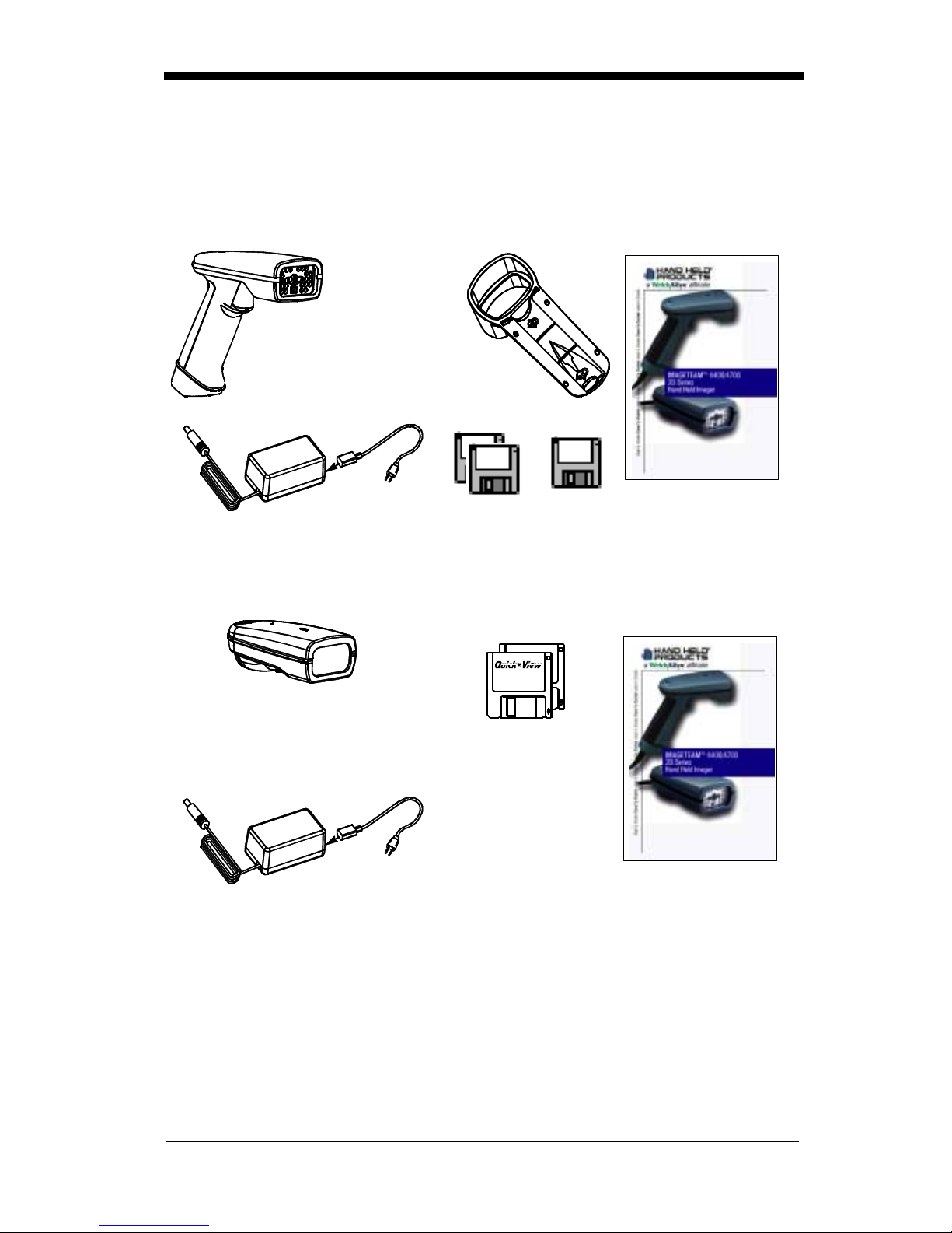
Unpacking the Imager
Open the carton. The shipping carton or container should contain:
IMAGETEAM 4400:
IMAGETEAM 4400
Hand Held Imager
Holder
Universal Power Supply
and Power Cable
IMAGETEAM 4700:
IMAGETEAM 4700
Hand Held/Fixed
Mount Imager
Quick*View
Visual Menu
User’s Guide
Demonstration
Diskettes
Demonstration
Diskettes
User’s Guide
Universal Power Supply
and Power Cable
• Check to make sure everything you ordered is present.
• Save the shipping container for later storage or shipping.
• Check for damage during shipment. Report damage immediately to the
carrier who delivered the carton.
1 - 2
Page 15
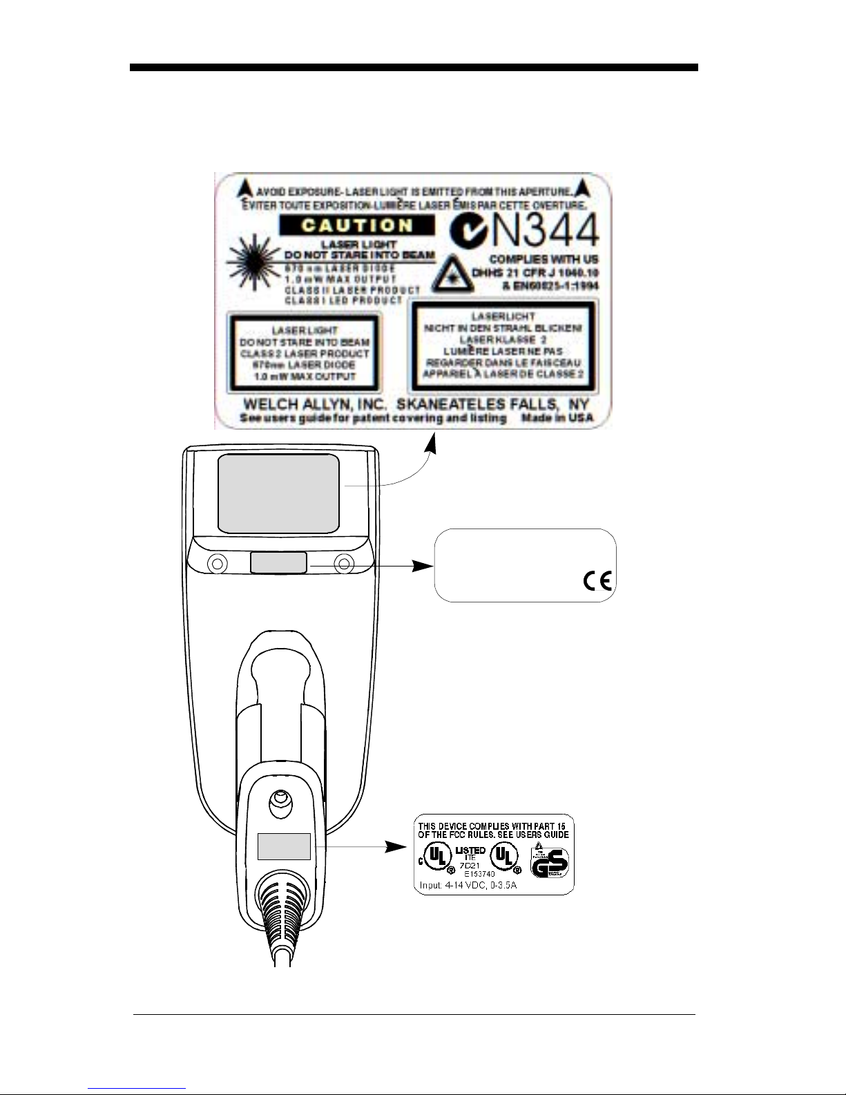
IT4400 Imager Ide ntifi cation
Enlarged View of Label
Model# = 4400XX-XX
Manufactured = July 1999
Seria l # = P-12- 34567
S/W = 34567001/4400
Hand Held IT4 400 I mag er
Bottom View
1 - 3
Page 16
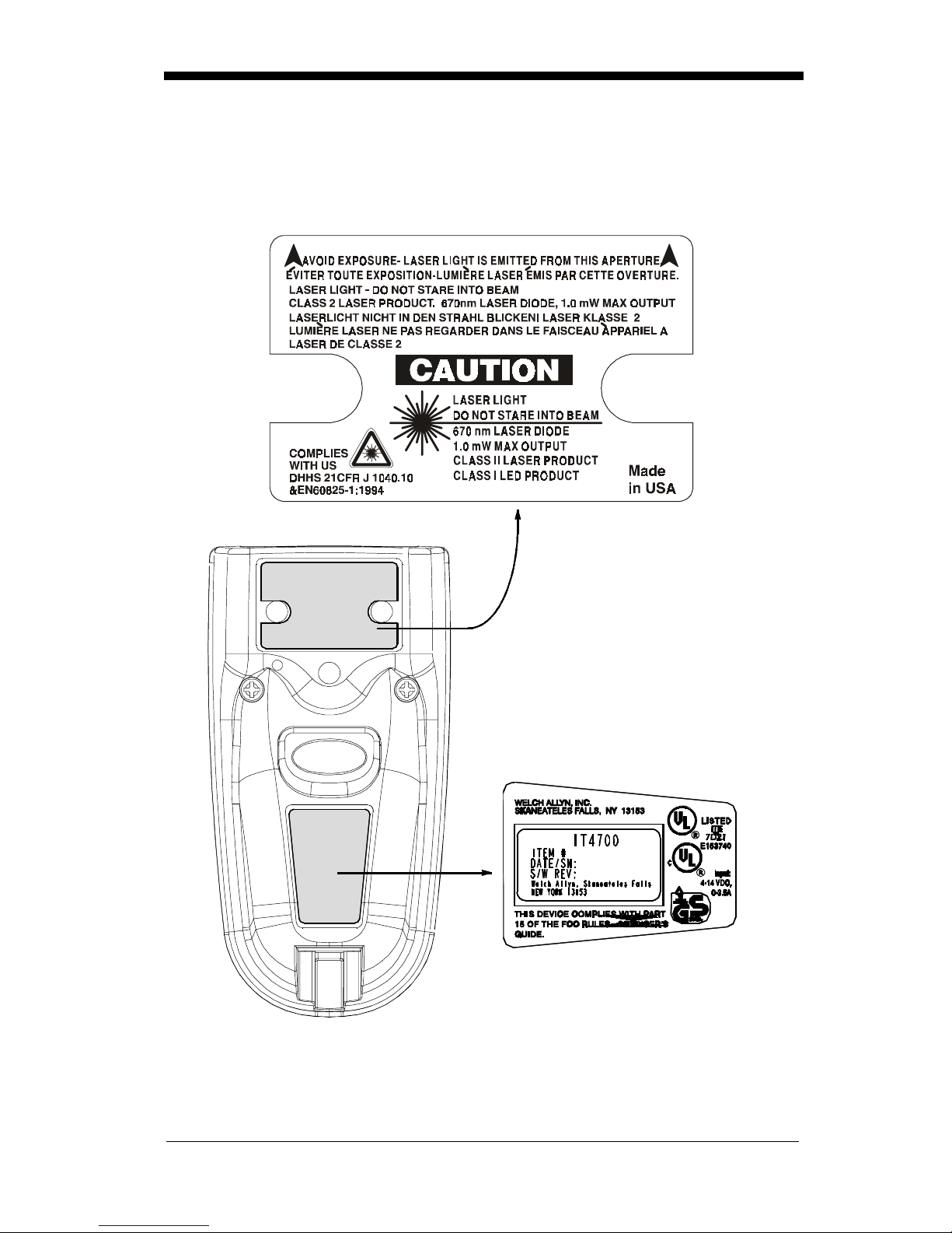
IT4700 Imager Ide ntifi cation
Enlarged View of Label
Hand Held IT4700 Imager
Bottom View
1 - 4
Page 17

Laser and LED Safety
The Laser A iming subsystem p rojects 670 nm laser light onto the bar code target
to define the optical field of view. The projected pattern consists of a central
cross and four 90 de gree corner sections. T his pattern is gener ated by a lens and
diffractive component positioned at the output of the enclosed laser diode. This
projected pattern assists the operator to frame the bar code being scanned.
The Good Read Indicator and the LED Illumination Array have been tested in
accordance with the spe ci ficati on “Safety of Laser Products” EN 60825-1:1994,
Issue 2, June 1997 and found to satisfy the requirements of Class 1. Class 1
optical systems are consi dered safe under r easonably foreseeab le cond itions of
operation. The Aiming Laser has been tested in accordance with the
specification “Safety of Laser Products” EN 60825-1:1994, Issue 2, June 1997
and found to satisfy the requirements of Class 2. Class 2 systems are
considered to emit visible radiation in the wavelen gth range from 400 nm to 700
nm. Eye protection is normally afforded by aversion responses including the
blink reflex. It is recommended that you do not stare into the beam or cause
others to stare into the beam.
1 - 5
Page 18
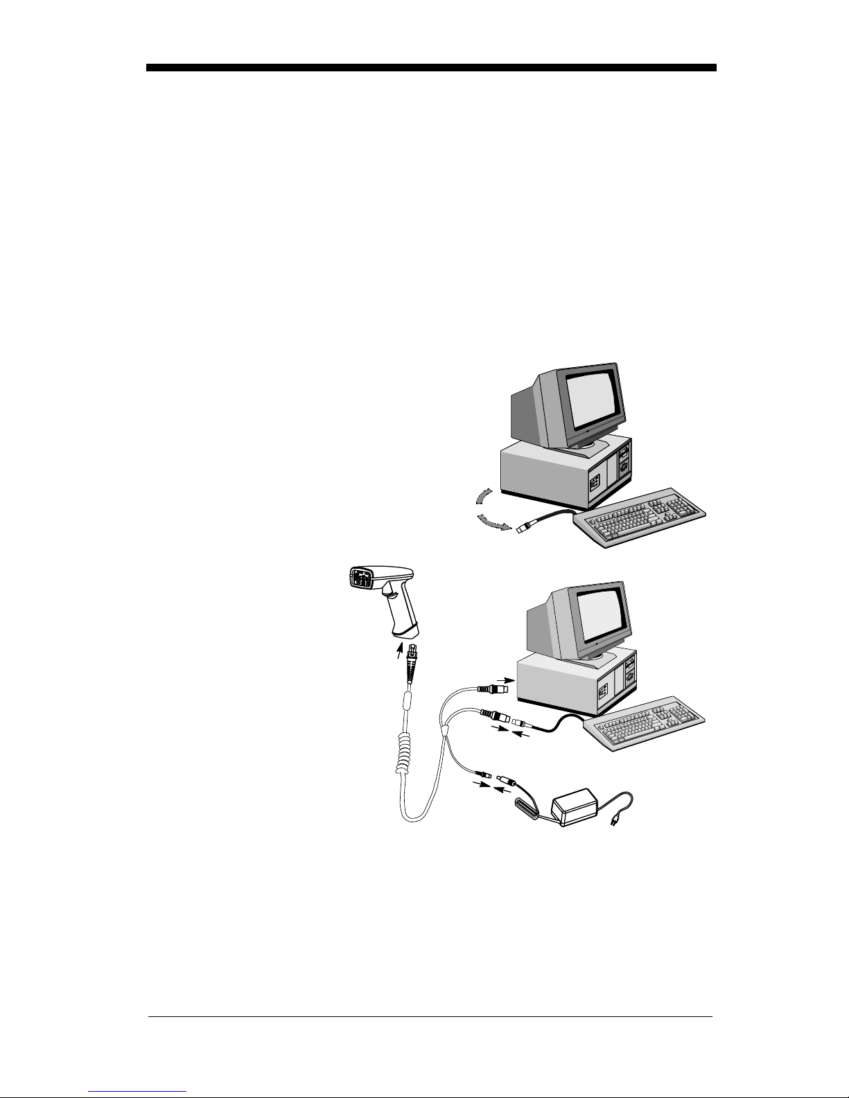
Connecting the Scanner When Powered by Host
(Keyboard Wedge)
A scanner can be connected between the keyboard and PC as a “keyboard
wedge,” plug ged into the s erial p ort, or conn ected to a por table data terminal in
wand emulation or non decoded output mode.
Note: Only un its ordered from the factory with keyboar d wedge capability can be
connected as keyboard wedge units.
The following is an example of a keyboard wedge connection:
1. Turn off power to the terminal/computer.
2. Disconnect the keyboard cable from
the back of the terminal/computer.
Disconnect
3. Connect the appropriate interface cable to
the scanner and to the
terminal/
computer. The scanner will beep twice.
4. Turn the terminal/computer power back on.
5. Verify the scanner
operation by scanni ng
a bar code from the
back cover of this
manual. The scanner
will beep once.
The scanner is now connected and read y to communicate with your terminal/PC.
You must program the scanne r for your inter face befor e bar code data can be
transmitted to your terminal/PC. If you are using the scanner as a keyboard
wedge, see"Terminal Interface" on page 2-4. If the scanner is connected via a
serial port, turn to "Connecting the Scanner to a Serial Port" on page 2-10.
1
3
2
4
1 - 6
Page 19
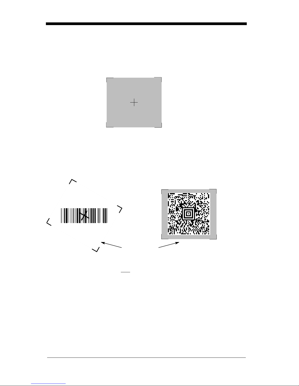
Reading Techniques
The hand-held Ima ger has a view finder (shown be low) wh ich is similar to those
on cameras. The view finder allows you to position the code within the field of
view.
The illustration below shows where to aim the red illuminated beam over the
symbol for a good read. Center the symbology in the view finder. The entire
symbology must be within the view finder (aiming beam). The view finder
changes size as you move the Imager closer to or farther away from a code.
Linear bar code 2D Matrix symbol
Note: The symbols can be in any orientation for the Imager to read.
The view finder is smaller when the Imager is closer to the code and larger when
it is farther from the code. Symbologies with smaller bars or elements (mil size)
should be read closer to the unit. Symbologies with la rger bars or elements (m il
size) should be read f arthe r from th e unit. (see "Depth of Field Charts "on page
1-8.) To read single or multiple symbols (on a page or on an object), hold the
Imager at an appropr iate distance fro m the target, pull the trigger , and center the
view finder cross hairs on the symbol.
View Finder
(Aiming Beam)
1 - 7
Page 20

Depth of Field Charts
Depth of Fiel d for High Densi ty Imager (2" No mina l Focus)
Code Size Near Distance Far Distance
QR 6.6 mil (0.017 cm) 1.7 inches (4.3 cm) 2.4 inches (6.1 cm)
Data Matrix 6.6 mil (0.017 cm) 1.7 inches (4.3 cm) 2.4 inches (6.1 cm)
Linear 4 mil (0.01 cm) 1.6 inches (4.1 cm) 2.5 inches (6.4 cm)
OCR 6 pt. (20 cpi) 2 inches (5.1 cm) 3.5 inches (8.9 cm )
Depth of Field for High Density10 Imager (3" Nominal Focus)
Code Size Near Distance Far Distance
QR 10 mil (0.025 cm) 2.0 inches (5.1 cm) 4.0 inches (10.2 cm)
Data Matrix 10 mil (0.025 cm) 2.0 inches (5.1 cm) 3.5 inches (8.9 cm)
Linear 5 mil (0.013 cm) 2.75 inches (7.0 cm) 3.75 inches (9.5 cm)
OCR 12 pt. (12 cpi) 2 inches (5.1 cm) 5 inches (12.7 cm)
Depth of Fiel d for Long Range Imager (5" Nominal Focus)
Code Size Near Distance Far Distance
Linear 7.5 mil (0.019 cm) 3.0 inches (7.6 cm) 5.0 inches (12.7 cm)
Linear 10 mil (0.025 cm) 2.5 inches (6.4 cm) 4.75 inches (12.1 cm)
Linear 15 mil (0.038 cm) 2.0 inches (5.1 cm) 7.5 inches (19.1 cm)
Data Matrix 15 mil (0.038 cm) 2.5 inches (6.4 cm) 4.0 inches (10.2 cm)
Aztec or QR 15 mil (0.038 cm) 3.5 inches (8.9 cm) 5.0 inches (12.7 cm)
Maxicode 35 mil (0.089 cm) 2.0 inches (5.1 cm) 9.0 inches (22.9 cm)
1 - 8
Page 21

2
Programming
Introduction
Use this section to progra m the hand-held Imager.
This programming section contains the following menuing selections:
• General Sel ections
• Terminal Interface Selections
• Keyboard Selections
• Communication Set tings
• Imager Selection s
• Output Selections
• Prefix/Suffix Selections
• Data Formatter Selections
• Output Sequence Selections
2 - 1
Page 22

Reset Factory Settings
All operating parameters are stored in nonvolatile memory resident in the
Imager, wher e they are permanently retai ned in the event of a power inte rruption.
When you receive you r Imager, certa in operating param eters have already b een
set. These are the factory defaults, indicated by the symbol “✱” on the
programming menu pages (beneath the default program ming symbo l). Default
charts begin on page 5-1.
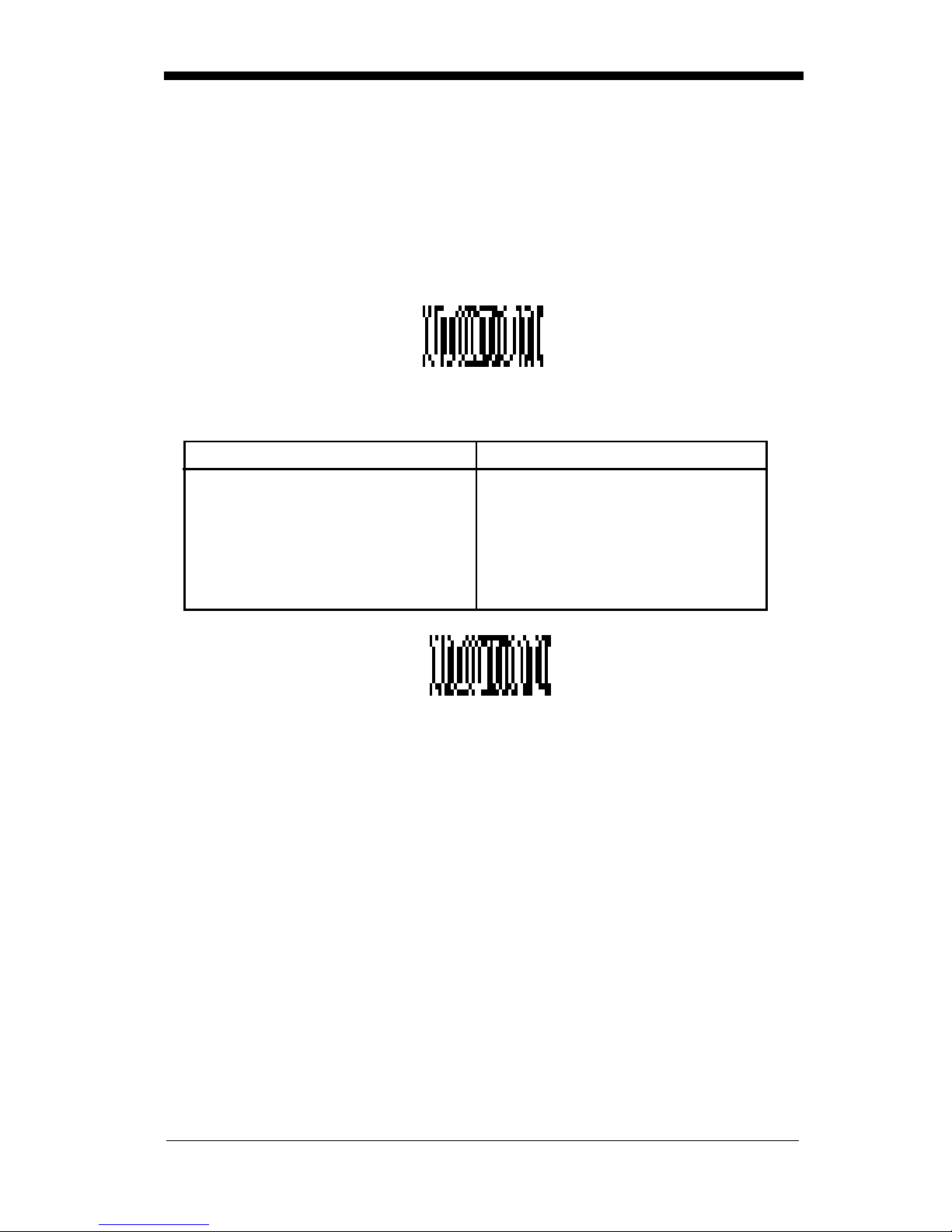
Depending on yo ur model, sca n one of the fo llowing ba r codes to set th e imag er
to the o riginal factory settings, cle aring any p rogramming changes you may have
made.
HD
LR
HD10
Status Check
Read the Show S oftware Re vision symbol to tran smit the soft ware revisi on level
to the host terminal. The software revision will be printed out as
“REV_SW:$ProjectRevision: 1.xx$;REV _WA:31204734-xxx.”
Read the Show Data Formats symbol to transmit t he existing D ata Format Edito r
formats. One format per line will be printed out.
Show Software
Revision
2 - 2
Show Data Formats
Page 23

All Symbologies
If you want to decode all the symbologies allowable for your scanner, scan the
All Symbologies On code.
All Symbologies
On
All Symbologies
Off
Revision Select i ons
Both the following pro gramming codes would not nor mally be needed unless you
have a problem with the unit. An Application Support Representative may
request the boot code or power P C revision information in orde r to trouble shoot
a problem.
Boot Code RevisionPower PC Revision
2 - 3
Page 24

Terminal Interface
IMAGETEAM 44 00 and 4700 scann ers are factory progr amm ed for a keyboar d
wedge interface to an IBM PC AT with a USA keyboard. If this is your interface
and you do not need to modify the settings, skip to page 2-16 for Imager
Selections.
If your interface is not a standard PC AT, refer to the "Supported Terminals
Chart" on page 2-5 and locate the Terminal ID number for your PC. Scan the
Terminal ID bar code below, then scan the numeric bar code(s) on the inside
back cover of this manual to program the scanner for your terminal ID. Scan
Save to save your selection.
For example, an IBM PS/2 terminal has a Terminal ID of 002. You would scan
the Ter minal ID bar code, then 0, 0, 2 from the inside back cover, then Save. If
you m ake an error wh ile scanning the digits (before scanning Save), scan the
Discard code on the back cover and scan the digits and the Save code again.
Factory Default = 03
Terminal ID
Save
2 - 4
Page 25

Supported Terminals Chart
Terminal Model(s)
Terminal
DEC PC433 SE (Portable PC) 003
DELL Latitude (Portable PC) 003
DTK 486 SLC (Portable PC) 003
Fujitsu Stylistic (Portable PC) 003
HHLC (Code 128 Emulation)
089
IBM PC X 001
IBM PS/2 25, 30, 77DX2 002
IBM
IBM
IBM
IBM
AT, PS/2 30-286, 50, 55SX, 60, 70, 003,
70-061, 70-121, 80
AT Compatibles Keyboard Emulation
(Non-wedge)
Thinkpad 360 CSE, 34, 750
(P ortable PC)
Thinkpad 365 , 755 CV
(P ortable PC)
003
097
003
IBM AT Thinkpad 106
Midwest Micro Elite TS 30 PS (Portable PC) 003
Mitak 4022 (Portable PC) 003
Olivetti M19, M24, M28, M200 001
I.D.
*
Olivetti M240, M250, M290, M380, P500 003
Reliasys TR 175 003
RS-232 TTL 000
Televideo 990, 995, 9060 002
Texas Instruments Extensa 560CD (Portable PC) 003
Toshiba 2600 (Portable PC) 003
Toshiba Satellite T1960, T2130, CS (Portable PC) 003
Zenith Z-note (Portable PC) 003
* This capability is not available for the IT4700. Contact the factory if this capability is
needed for the IT4700.
Note: These interfaces are available only for units that have 1 megabyte of
program me mory. The software revision indicate s the memory s ize. If you
are not certain of your unit’s memory, please contact Welch Allyn’s
Application Support (see page 10-5).
2 - 5
Page 26
Keyboard Country
Scan the Program Keyboard Country bar code below, then scan the numeric
bar code(s) from the inside back cover, then the Save bar code to program the
keyboard for your country. As a general rule, the following characters are not
supported by the scanner for countries other than the United States:
@ | $ # { } [ ] = / ‘ \ < > ~
Keyboard Country
Country Code Scan Country Code Sc an
Belgium.....................1 Italy........................5
Denmark...................8 Norway...................9
Finland......................2 Spain......................10
France ......................3 Switzerland............6
Germany/Austria....... 4 USA
Great Britain .............7
(Default)
.........0
2 - 6
Save
Page 27

Keyboard Style
This programs keyboard styles, such as Caps Lock and Shift Lock.
Default =
Regular.
Regular
Caps Lock
Shift Loc k
to U.S. keyboards.)
Automa tic Caps Lo ck
software tracks and r eflects if you have Caps Lock on or of f (AT and PS/2 only).
This selection can only be used with systems that have an LED which notes the
Caps Lock status.
Emulate E xte rnal Keyb oa rd
keyboard (IBM AT or equivalen t), but sh ould not be use d for laptops. To connect
the scanner to a laptop, use "Automatic Direct Connect Mode On"on page 2-8.
is used when you normally have the Caps Lock key off.
is used when you normally have the Caps Lock key on.
is used when you normall y have the Shift Lock key on. ( Not common
is used if you cha nge the Caps Lo ck key on and off. T he
should be scanned if you do no t have an exter nal
* Regular Caps Lock
Shift Lock
Automatic
Caps Lock
Emulate External
Keyboard
2 - 7
Page 28

Keyboard Modifiers
This modifies special keyboard features, such as CTRL+ A SCII codes and Turbo
Mode.
Control + ASCII Mode On
control characters for values 00-1F. Refer to "Keyboard Function
Relationship s" on page 2-9 for CTRL+ ASCII Values.
Control + ASCII
Mode On
Turbo Mode
use with IB M AT onl y.) If th e terminal drops character s, do not u se Turbo M ode.
- The scanner send s character s to an IB M AT term inal faster. (Fo r
- The scanner sends key combinations for ASCII
Default = Off
* Control + ASCII
Mode Off
Default = Off
Turbo Mode On
Numeric Keyp ad Mod e
numeric keypad.
Default = Off
- Sends numeric characters as if entered from a
* Turbo Mode Off
Numeric Keypad
Mode On
Automatic D ir ect Conn ect
keyboard is disabled when you plug in the scanner. This selection can also be
used if you h ave an IBM AT style terminal a nd the system is drop ping characters.
Default = Off
Automatic Direct
Connect Mode On
2 - 8
* Numeric
Keypad Mode Off
- Use this selection if you are using a laptop whose
* Automatic Direct
Connect Mode Off
Page 29

Keyboard Func tion Re lationships
The following Keyboard Function Code, Hex/ASCII Value, and Full ASCII
“CTRL”+ relationships apply to all terminals that can be used with the scanner.
Function Code HEX/ASCII Value Full ASCII “CTRL” +
NUL 00 2
SOH 01 A
STX 02 B
ETX 03 C
EOT 04 D
ENQ 05 E
ACK 06 F
BEL 07 G
BS 08 H
HT 09 I
LF 0A J
VT 0B K
FF 0C L
CR 0D M
SO 0E N
SI 0F O
DLE 10 P
DC1 11 Q
DC2 12 R
DC3 13 S
DC4 14 T
NAK 15 U
SYN 16 V
ETB 17 W
CAN 18 X
EM 19 Y
SUB 1A Z
ESC 1B [
FS 1C \
GS 1D ]
RS 1E 6
US 1F -
2 - 9
Page 30
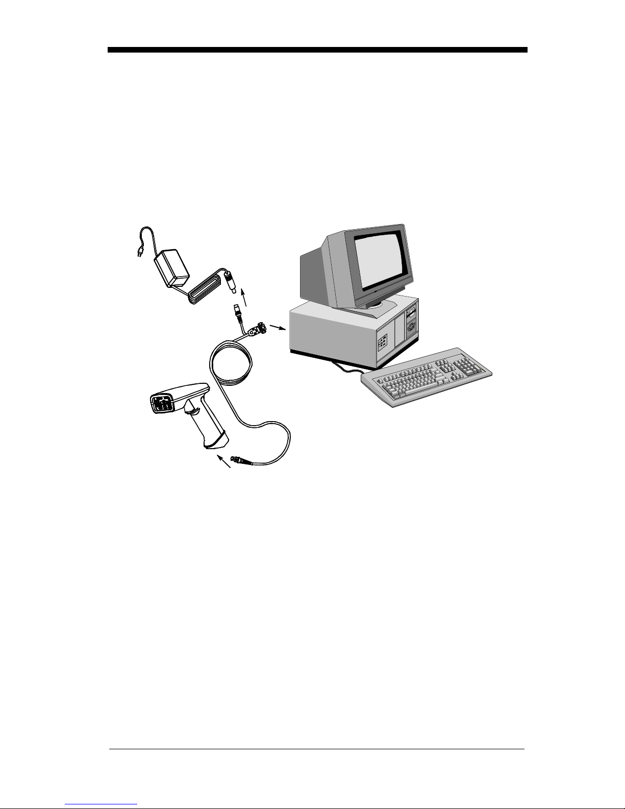
Connecting the Scanner to a Serial Port
6. Turn off power to the terminal/computer.
7. Connect the interface cable to the scanner.
8. Connect the interface cable to the 5 or 14 VDC power supply and plug in the
power supply. The scanner will beep twice.
9. Connect the interface cable to the terminal/computer.
Power Supply
1
10. Turn the terminal/computer power back on.
11. Verify the scanner operation by scanning a bar code from the back cover of
this manual. The scanner will beep once.
The scanner is now connected and read y to communicate with your terminal/PC.
Turn to "Communication Settings" on page 2-11 to program the communication
parameters for a serial inter face.
2
3
Interface Cable
2 - 10
Page 31

Communicat ion Settings
<Default All RS-232 Communication Settings>
Parity
Parity provides a means of checking character bit patterns for validity. The
Imager can be configured to operate under Mark, Space, Odd, Even, or No
(None) parity options. The host terminal must be set up for the same parity as
the Imager, to ensure reliable communication.
Mark
Odd
Space
Even
* None
2 - 11
Page 32

Baud Rate
This sets the baud rate from 300 bits pe r second to 115,200 bits per second (see
next page). Programming baud rate causes the data to be sent at the specified
rate. The host terminal must be set to the same baud rate as the Imager to
ensure reliable communication.
300 600
1200
19200
2400
96004800
* 38400
2 - 12
Page 33

Baud Rate,
57600 115200
continued
Word Le ngth Data Bits
You can set t he Word Lengt h at 7 or 8 bits of da ta per character. If an applicatio n
requires only ASCII Hex characters 0 through 7F decimal (text, digits, and
punctuation), select 7 data bits. For applications requiring use of the full ASCII
set, select 8 data bits per character.
7 Data Bits
Wo rd Le ngth Stop Bits
Word Length can be set to one or two stop bits.
* 1 Stop Bit
* 8 Data Bits
2 Stop Bits
2 - 13
Page 34

Hardware Flow Control
When hardware flow control is on, the software checks for a CTS signal before
sending data. This option is useful when your application supports the CTS
signal.
On
* Off
Software Flow Control
This allows control of data transmission from the Imager using software
commands from the host device. When this feature is turned off, no data flow
control is used. When Data Flow Control is turned on, the host device suspen ds
transmission by sending the XOFF character (DC3, hex 13) to the Imager. To
resume transmission, the host sends the XON character (DC1, hex 11). Data
transmission continues where it left off when XOFF was sent.
On
* Off
2 - 14
Page 35

Serial Triggering
This provides a means of sending a serial trigger command to s tart and stop
decoding. When this feature is turned off, the Imager will not respond to serial
trigger commands. When serial triggering is turned on, the Imager requires a
serial trigger chara cter to activate scanning and deco ding. The unit continues to
scan and decode bar codes unt il the Trigger Off character turn s off the scanner,
or a time out occurs.
On th e " Deci mal to Hex to ASCII Conversion Chart" on page 2-34, find the hex
characters you want to use to turn the trigger on and off. Locate the decimal
values for those characters and scan the 2 digits for each one from the
Programming Chart in the back of this manual.
When Serial T riggering is On, the defa ult Trigger On decim al character is 18 (hex
12, DC2), and the default Trigger Off decimal character is 20 (hex 14, DC4).
* OffOn
Trigger On ‡ Trigger Off ‡
‡ A one to three digit decimal number and Save are required after reading
this programming symbol. See "Decimal to Hex to ASCII Conversion
Chart" on page 2-34, and the Programming Chart (inside back cover).
* Trigger Defaults
2 - 15
Page 36

Power Sav i ng Mode
This provides control of the Imager’s power consumption, as follows:
Low Power
attempt
during the read attempt, and powers down after the image capture is complete.
Medium Power
enhances motion tolerance.
trigger is pulled, going into a “doze” (low power) state after each read attempt.
The Imager powers down ten seconds after the image capture is complete.
Normal Power
trigger is pulled. The Imager doesn’t go into a “doze” state after each read
attempt, but m ay power down a fter two minutes if Power Hold Mode is turned Off.
Low Power Medium Power
draws low LED current during image capture, allowing one read
only
for each tri gger pull. The Ima ger is less tolerant of ha nd movement
draws a normal LED current during image capture which
Medi um Power
draws a normal LED current, attempting to read as long as the
attempts to read as long as the
Power Hold Mode
Power Hold On keeps the Imager in a ready to read state. To conserve power,
this selection may be turned
two minutes. When you are ready to use the Imager again, restore power by
pressing the trigge r.
On * Off
2 - 16
* Normal Power
Off
and the unit will power down if not used within
Page 37

LED Power Level
This selection allows you to adjust LED brightness.
Off
is used when no illumination is needed.
sufficient.
High
(the default) is the brightest setting.
Low
is used if low illumination is
Off
* High
Low
LED Flashing
If LED Flashing is turned off, the average current draw is increased and the
aiming light won’t illuminate while the scanner reads a bar code.
Off † * On
† If LED Flashing is turned off, the average current draw is increased and
the view finder won’t illuminate duri ng the rea ding phase.
2 - 17
Page 38

Aimer Delay
The aimer delay allows a delay time for the operator to aim the scanner before
the picture is taken. Use these codes to set the time between when the trigger
is pulled and when th e picture is taken. During t he delay time, the aiming light
will appear, but the LEDs won’t turn on until the delay time is over.
200 milliseconds
* Off
(no delay)
400 milliseconds
Aimer Timeout
Use this selection to set a timeout (in second s) of the Imager’s aiming light when
the device is not reading a bar code.
Default setting = 60 seconds
‡ A one- to three digit number and Save are required after reading this
programming symbo l. Refer to the Programming Chart (inside back
cover).
2 - 18
Set Timeou t ‡
Page 39

Aimer Interval
Aimer Interval turns off the aiming light, or programs the aimer to come on at
certain intervals when re ading symbols with the scanner. You may program the
scanner to use t he aimer Every Read, Ever y Second Read, or Every Thir d Read.
You may also pr ogram th e scanner to use the a imer ever y “x” reads, by e ntering
a number from 0 to 999 to indica te “x.”
Off
Every Second Read
* Every Read
Every Third Read
‡ A one- to three digit number and Save are required after reading this
programming symbo l. Refer to the Programming Chart (inside back
cover).
Every “x” Reads
‡
2 - 19
Page 40

AutoTrigger
Two AutoTrigger Modes are available: Scan Stand and Presentation Mode.
When a unit is in Scan Stand mode, the LED shines at the symbol on the base
of the stand which te lls it to rem ain idle. When a different cod e is pre sented, the
Imager is triggered to read the new code.
Presentation mode is fo r those applications where a scan stand will not work, i.e.,
when large packages mu st be scann ed. To program the devi ce for presentat ion
mode, refer to "Prese ntation Mod e" on page 2-21.
Scan S tand
This selection programs the Imager to work in a Scan Stand.
On* Off
Scan Stand LED Intensity
This sets the idle LED intensity when the Imager is in Scan Stand mode. When
a unit is in Scan Stand mode, the LED shines at the symbol on the base of the
stand which tel ls it to remain idle. Wh en a different code is present ed, the Imager
is triggered to read the new code. If the Imager has difficulty going back to
reading the Scan St and’s fixed cod e, for instance, in a low lig hting situation, you
may want to adjust the Scan Stand LED Intensity. A two digit number between
15 and 75 must be input after the Scan Stand LED Intensity prog rammi ng code
is scanned. A 15 corresponds to the lowest intensity level, and a 75 corre sponds
to the highest intensity level. 15 is the default setting.
Note that when the unit is triggered to read a code, the unit uses the LED power
level specified through "LED Power Level" on page 2-17.
Set Scan Stand LED Intensity
2 - 20
Page 41

Scan Stand Lights
You can turn off the scanner li ght when the imager is in idle mode in a scan stand.
* OnOff
Presentation Mode
This programs the scanner to work in Presentation Mode.
Default = Off.
On* Off
Presentation Reread Delay
This sets the time period before the scanner can read the
second time. Setting a reread delay protects against accidental rereads of the
same bar code. Longer delays are effective in minimizing accidental rereads at
POS (point of sale). Us e shorter delays i n applicatio ns where repet itive bar code
scanning is required. Entries are in milliseconds, up to 10,000.
Default = 500.
Presentation R ere ad Delay
same
bar code a
Presentation Def ault
Defaults all presentation mode settings.
Presentation Reread Delay 500 ms (1/2 sec.), Presentation Aimer On.
Defaults
Presentation Default
=
Presentation Mode Off,
2 - 21
Page 42

Presentation A imer
You can turn on or off the scanner’s aiming light when the device is not reading
a bar code.
Off
* On
Zoom
Use Zoom to zoom in and read smaller m atr ix codes. The zoom selection does
not affect reading of linear bar codes. The factory default setting is Off. (High
Density scanners are programmed with the zoom turned on when shipped from
the factory. If you scan the LR Factory Default Settings code on page 2-2, the
zoom will be turned off.)
On
* Off
2 - 22
Page 43

Zoom P l acement
This lets you positi on the r ead area (crosshairs ) of the Ima ger wh en it is in zo om
mode. The Zoom Vertical moves the crosshairs vertically, and the Zoom
Horizontal move them hor izonta lly, as illustr ated below :
Note: When zoom is turn ed on, the field of view of the Imag er is reduced, making
it more difficult for the Imager to read large matrix symbols.
Zoom Horizon tal
3 4 5 6
3
4
5
6
Zoom Vertical
After the Zoom Placement code below is scanned, you must scan a 1 digit code
(inside ba ck cover) to enter the zoom positi on you want. The default for both
vertical and horizon tal placement is 4, wh ich centers the crosshairs in the fi eld of
view.
Zoom Vertical
Zoom Horizontal
Note: The default setting for the H D Imager is a Zo om Verti cal of 6 and, for the
HD10, the default setting is a Zoom Vertical of 5.
2 - 23
Page 44

Beeper Volume
Off
Medium
Power Up Beeper
Low
* High
* On
Off
Output Sequence Bee per
If you are using an Outpu t Sequence (see "Output Seq uence Overview" on page
2-41), you may want to hear a beep after each bar code as it is read. Scan
Output Sequence Beeper On to enable this feature, or Off to disable it.
* On
Off
2 - 24
Page 45

Beep On Decode
If you want the scanner to beep each time it reads a bar code, le a v e t h is setting
On. If you don’t want it to beep on each read, but do want it to beep for other
events, set this selection to Off.
* On
Beeper Default
Defaults all beep er setti ngs.
On, Output Sequence Beeper On, Beep On Read On.
Defaults
=
Beeper Defaul t
Beeper Volume High, Pow er Up B eeper
Off
2 - 25
Page 46

Intercharacter, Interfunction,
and Intermessage Delays
Some terminals dr op information (ch aracters) if data comes thr ough too quickly.
Intercharacter, interfunction, and intermessage delays slow the transmission of
data, which increases data integrity.
Each delay is composed of a 5 millisecond step. You can program up to 99 steps
(of 5 ms each).
Intercharacter Delay
This is a delay of up to 495 milliseconds (in multiples of 5) placed between the
transmission o f each character of scanned data. You can pr ogram up to 99 steps
(of 5 ms each). Scan the Intercharacter Delay bar code below, then scan the
number of steps, and the SAVE bar code from the inside back cover.
Note:
To remove this delay, scan the Intercharacter Delay bar code, then set the
number of steps to 00. Scan the SAVE bar code from the inside back cover.
If you make an error while scanning the digits (before scanning Save),
scan Discard on the back cover and scan the correct digits and Save
again.
Prefix Scanned Data Suffix
1 2345
Interchara cter Delay
Intercharacter Delay
2 - 26
Page 47

Interfunction Delay
This is a delay of up to 495 milliseconds (in multiples of 5) placed between the
transmission of each segm ent of the message string . You can program up to 99
steps (of 5 ms each). Scan the Interfunction Delay bar code below, then scan
the number of steps, and the SAVE bar code from the inside back cover.
Note: If you make an error while scanning the digits (before scanning Save),
scan Discard on the back cover and scan the correct digits and Save
again.
Prefix Scanned Data Suffix
1 2345STX HT CR LF
Interfunction D elays
Interfunction Delay
To remove this dela y, scan the Interfunction Delay bar code, the n set the number
of steps to 00. Scan the SAVE bar code from the inside back cover.
2 - 27
Page 48

Intermessage Delay
This is a delay of up to 495 milliseconds (in multiples of 5) placed between each
scan transmission. You can program up to 99 steps (of 5 ms each). Scan the
Intermessage Delay bar code below, then scan the number of steps, and the
SAVE bar code from the inside back cover.
Note:
To remove this delay, scan the Intermessage Delay bar code, then set the
number of steps to 00. Scan the SAVE bar code from the inside back cover.
If you make an error while scanning the digits (before scanning Save),
scan Discard on the back cover and scan the correct digits and Save
again.
2nd Scan Transmission1st Scan Transmission
Intermessage Delay
Intermessage Delay
2 - 28
Page 49

Prefix/Suffix Overview
When a bar code is scanned, additional information is sent to the host computer
along with the bar code data. This group of bar code data and additional,
user-define d data is called a “message str ing.” The selection s in this section are
used to build the user-def ined data into the message string.
Prefix and Suffix char acters are data characters that can be sent before and after
scanned data. You can specify if they should be sent with all symbologies, or
only with specific symbologies. The following illustration shows the breakdown
of a message string:
Prefix Scanned Data Suffix
1-10
alpha
numeric
characters
variable
length
1-10
alpha
numeric
characters
Points to Keep In Mind
• It is not necessary to build a message string. The selections in this
chapter are only used if you wish to alter the default settings.
prefix = None. Default suffix = None
• A prefix or suffix may be added or cleared from one symbology or all
symbologies.
• You can add any prefix or suffix from the "Decimal to Hex to ASCII
Conversion Chart" on page 2-34, plus Code I.D. and Aim I.D.
• You can string together several entries for several symbologies at one
time.
• Enter prefix es and suffixes in the orde r in which you want th em to appear
on th e output.
.
Default
2 - 29
Page 50

Adding a Prefix or Suffix
1. Scan the Add Prefix (page 2-32) or Add Suffix symbol (page 2-32).
2. Determine the 2 digit Hex value from the "Symbology Chart "on page 2-33
for the symbology to which you want to apply the prefix or suffix.
3. Scan the 2 hex digits from the Programming Chart inside the back cover or
scan 9, 9 for all symbologies.
4. Determine the hex value from the "Symbology Chart "on page 2-33 for the
prefix or suffix you wish to enter.
5. Scan the 2 digit hex value from the Programming Chart inside the back
cover.
Note:
Note:
6. Scan Save to exit and save, or scan Discard to exit without saving.
Repeat Steps 1-6 to add a prefix or suffix for another symbology.
Example: Add a Suff ix to a specific symbolo gy
To send a CR (carriage return )Suffix for UPC only:
1. Scan Add Suffix.
2. Determine the 2 digit hex value from the "Symbology Chart" on page 2-33 for
3. Scan 6, 3 from the Programming Chart (inside back cover).
4. Determine the hex value from the "Decimal to Hex to ASCII Conversion
5. Scan 0, D from the Programming Chart (inside back cover).
6. Scan Save, or scan Discard to exit without saving.
Repeat Steps 4 and 5 for every prefix or suffix character.
To add the Code I.D., scan 5, C, 8, 0.
To add AIM I.D., scan 5, C, 8, 1.
To add a backslash (\), scan 5, C, 5, C
UPC.
Chart" on page 2-34 for the CR (carriage return).
.
Clearing One or All Prefixes or Suffixes
You can clear a single prefix or suffix, or clear all prefixes/suffixes for a
symbology. When you Clear One Prefix (Suffix), the specific character you
select is deleted from the symbology you want. When you Clear All Prefixes
(Suffixes), all the prefixes or suffixes for a symbology are deleted.
1. Scan the Clear One Prefix or symbol.
2. Determine the 2 digit Hex value from the "Symbology Chart "on page 2-33
for the symbology from which you want to clear the prefix or suffix.
3. Scan the 2 digit hex va lue from the Prog ramming Chart inside the back cover
or scan 9, 9 for all symbologies.
Your change is automatically saved.
2 - 30
Page 51

Add a Car riage Ret ur n Suffi x to A l l Symbologies
Scan the following bar code if you wish to add a Carriage Return Suffix to all
symbologies at once. This action first clears all current suffixes, then programs
a carriage retur n suffix for al l symbol ogies.
Add CR Suffix
All Symbologies
Add a Code I .D. Prefix to All Symb ologies
This selection allows you t o turn on ( or off) tr ansmission of a Code I.D. b efore the
decoded symbology. (See the "Symbology Chart"on page 2-33 for the single
character cod e that identifies each symbology.) This acti on first clears all current
prefixes, then programs a Code I.D. prefix for all symbologies.
Add Code ID Prefix
All Symbologies
Add an AIM I.D. Prefix to All Symbologies
This selection a llows you to tu rn on (or o ff) transmission o f an AIM I.D. before the
decoded symbology. (See the "Symbology Chart"on page 2-33 for the single
character cod e that identifies each symbology.) This acti on first clears all current
prefixes, then pro gram s an AIM I.D . prefix f or all symbolo gi es.
Add AIM ID Prefix
All Symbologies
(See AIM Guidelines on Symbology Identifiers for more information on the AIM
symbology ID characters.)
2 - 31
Page 52

Prefix Ent rie s
Add Prefix †
Suffix Entrie s
Add Su f fi x †
Clear One Prefix †
Clear All Prefixes
Clear One
Suffix †
† One or more two digit numbers and Save are required after reading this
programming symbol. Refer to the Programming Chart (inside back cover).
Exit Selections
Save Discard
2 - 32
Clear All Suffixes
Page 53

Symbology Char t
Symbology
Australian 4 State
Aztec Code
BC412**
BPO 4 State
Canadian 4 State
Codabar
Codablock-F
Code 39
Code 49
Code 93/93i
Code 128
Code Z**
Data Ma trix
EAN
Iata 2 of 5
CodeIDAIMIDHex
ID
A[X41
z[z7A
g[X67
B[X42
C[X43
a[F61
q[O71
b[A62
l[T6C
i[G69
j[C6A
u[X75
w[d77
d[E64
f[R66
Symbology
Interleaved 2 of 5
Japanese Postal
Kix (Dutch) Postal
Maxicode
Micro PDF417
No Read
OCR
PDF417
Planet Code
Postnet
QR C ode
RSS/Composites
UPC
Vericode**
All Symbologies
CodeIDAIMIDHex
e[l65
J[X4A
K[X4B
x[U78
R[L52
o[Y6F
r[L72
L[X4C
P[X50
s[Q73
y[e79
c[E63
v[V76
†
ID
9C
99
Note: Prefix/Suffix entries for specific symbologies override the universal (All
Symbologies, 99) entry.
†
All Symbologies: Prefix/Suffix programming only!
** Not available in standard product. Only available when ordered in custom
firmware
2 - 33
Page 54

Decimal to Hex to ASCII Conversion Chart
Dec. Hex ASCII Dec. Hex ASCII Dec. Hex ASCII Dec. Hex ASCII
0 00 NUL 32 20 SP 64 40 @ 96 60 ‘
1 01 SOH 33 21 ! 65 41 A 97 61 a
2 02 STX 34 22 “ 66 42 b 98 62 b
3 03 ETX 35 23 # 67 43 C 99 63 c
4 04 EOT 36 24 $ 68 44 D 100 64 d
5 05 ENQ 37 25 % 69 45 E 101 65 e
6 06 ACK 38 26 & 70 46 F 102 66 f
7 07 BEL 39 27 ‘ 71 47 G 103 67 g
8 08 BS 40 28 ( 72 48 H 104 68 h
9 09 HT 41 29 ) 73 49 l 105 69 i
10 0A LF 42 2A * 74 4A J 106 6A j
11 0B VT 43 2B + 75 4B K 107 6B k
12 0C FF 44 2C , 76 4C L 108 6C l
13 0D CR 45 2D - 77 4D M 109 6D m
14 0E SO 46 2E . 78 4E N 110 6E n
15 0F SI 47 2F / 79 4F O 111 6F o
16 10 DLE 48 30 0 80 50 P 112 70 p
17 11 DC1 49 31 1 81 51 Q 113 71 q
18 12 DC2 50 32 2 82 52 R 114 72 r
19 13 DC3 51 33 3 83 53 S 115 73 s
20 14 DC4 52 34 4 84 54 T 116 74 t
21 15 NAK 53 35 5 85 55 U 117 75 u
22 16 SYN 54 36 6 86 56 V 118 76 v
23 17 ETB 55 37 7 87 57 W 119 77 w
24 18 CAN 56 38 8 88 58 X 120 78 x
25 19 EM 57 39 9 89 59 Y 121 79 y
26 1A SUB 58 3A : 90 5A Z 122 7A z
27 1B ESC 59 3B ; 91 5B [ 123 7B {
28 1C FS 60 3C < 92 5C \ 124 7C |
29 1D GS 61 3D = 93 5D ] 125 7D }
30 1E RS 62 3E > 94 5E ^ 126 7E ~
31 1F US 63 3F ? 95 5F _ 127 7F DEL
2 - 34
Page 55

Data Format Editor Overview
The Data Format Edi tor selections are used to edit scanned data. For example,
you can use the Data Format Editor to insert characters at certain points in bar
code data as it is scanned.
It is not necessary to use the Data Format Editor. A set of defaults for the data
format is already programmed in the scanner. The selections in the following
pages are used on ly if you wish t o alter the defau lt settings.
setting = none.
If you ha ve changed da ta format setti ngs, and wish to clear all formats and return
to the defaults, scan the Default Data Format code.
To Add a Data Format
1. Scan the Enter Data Format symbol (page 2-38).
2. Primary/Alternate Fo rmat
Determine if this will be your primary data format, or one of 3 alternate formats. (Alternate formats allow you “single shot” capability to scan one bar
code using a different data format. After the one bar code has been read,
the scanner reverts to the primary data format. See "Alternate Data
Formats" on page 2-40.) If you are progra mming the primary for mat, scan 0.
If you are programming an alternate format, scan 1, 2, or 3, depending on
the alternate format you are programming.
Default Data Format
3. Terminal Type
Refer to the "Supported Terminals Chart"on page 2-5 and locate the Terminal ID number for your PC. Scan three numeric bar codes on the inside back
cover to program the scanner for your terminal ID (you must enter 3 digits).
For example, scan 0 0 3 for an AT wedge.
4. Code I.D.
On page 2-33, find the symbology to which you want to apply the data format. Locate the Hex value for that symbology and scan the 2 digit hex value
from the Programm ing Chart.
5. Length
Specify what length (up to 9999 character s) of d ata will be a cceptable fo r this
symbology. Scan the four digit data length from the Programming Chart.
(Note: 50 characters is entered as 0050. 9999 is a universal number, indicating all lengths.)
6. Editor Commands
Refer to the "Format Editor Commands" on page 2-36. Scan the symbols
that represent the command you want to enter. 94 alphanumer ic characters
may be entered for each symbology data format.
7. Scan Save to save your entries.
2 - 35
Page 56

Other Programming Selections
• Clear One Data Format
This deletes one data format for one symbology. If you are clearing the
primary format, scan 0. If you are clearing an alternate format, scan 1, 2,
or 3, depending on the alternate format you are clearing. Scan the
Terminal Type (refer to the "Supported Terminals Chart"on page 2-5),
Code I.D. and the length of the format you want to delete. That length
data format for that symbology is deleted and all other formats are
unaffected.
• Save
This exits, saving any Data Format changes.
• Discard
This exits without saving any Data Format changes.
Format Editor Comma nds
Send Commands
F1 Send all characters followed by “xx” key or function code, starting from
current cursor position .
ASCII code, see "Decimal to Hex to ASCII Conversion Chart" on page 2-
34.)
F2 Send “nn” character s followe d by “xx” key or function code, starting from
current cursor position.
value (00-99) f or the number of char acters and xx stands for the hex value
for an ASCII code. See "Decimal to Hex to ASCII Conversion Chart" on
page 2-34.)
F3 Send up to but not including “ss” character (Search and Send) starting
from current curso r positi on, leavi ng cursor pointing to “ss” character
followed by “xx” key or function code.
stand for the hex values for ASCII codes, see "Decimal to Hex to ASCII
Conversion Chart" on page 2-34.)
F4 Send “xx” character “nn” time s (Inse rt) leaving cursor in current cursor
position.
see "Decimal to Hex to ASCII Conversio n Char t" on page 2-34, and nn is
the numeric value (00-99) for the number of times it should be sent.)
E9 Send all but the last “nn” characters, starting from the current curs or
position.
of characters that will not be sent at the end of the message.)
Syntax = F4xxnn
Syntax = E9nn
Syntax = F1 xx
Syntax = F2nnxx
(xx stands for the hex valu e for an ASCII code,
(nn is the numeric value ( 00- 99) f or the number
(xx stands for the he x value fo r an
(nn stands for the numeri c
Syntax = F3ssxx
(ss and xx both
Move Commands
F5 Move the cursor ahead “nn” characters from current cursor position.
Syntax = F5nn
of characters the c ursor should be move d ahead.)
F6 Move the cursor back “nn” characters from current cursor position.
Syntax = F6nn
of characters the cursor should be moved back.)
F7 Move the cursor to the beginning of the data string.
EA Move the cursor to the end of the data string.
2 - 36
(nn stands for the numeric value (00-99) for the number
(nn stands for the numeric value (00-99) for the number
Syntax = F7.
Syntax = EA
Page 57

Search Commands
F8 Search ahead for “xx” character from current cursor position, leaving
cursor pointing to “xx” character.
Syntax = F8xx
(xx stands for the hex
value for an ASCII code, see "Decimal to Hex to ASCII Conversion
Chart" on page 2-34.)
F9 Search back for “xx” chara cter from current curso r position, leaving cu rsor
pointing to “xx” cha racter.
Syntax = F9x x
(xx stands for the hex value for
an ASCII code, see " Decimal to H ex to AS CII Conversion Chart" on page
2-34.)
E6 Search ahead for the l ast instance of “xx” characte r from the curre nt cursor
positio n, then inc rement cursor.
Syntax = E6xx
(xx stands for the hex
value for an ASCII code, see "Decimal to Hex to ASCII Conversion
Chart" on page 2-34.)
E7 Search back for the last instance of “xx” character from the current curso r
positio n, then inc rement cursor.
Syntax = E7xx
(xx stands for the hex
value for an ASCII code, see "Decimal to Hex to ASCII Conversion
Chart" on page 2-34.)
Miscellaneous Commands
FB Suppress all occurrences of up to 15 different characters, starting at the
current cursor position, as the cursor is advanced by other commands.
When the FC command is encountered, the suppress function is
terminated. The cursor is not moved by the FB command. Syntax =
FBnnxxyy . .zz where nn is a count o f the number suppress characte rs in
the list and xxyy .. zz is the list of characters to be suppressed. (xx stands
for the hex value for an ASCII code, see "Decimal to Hex to ASCII
Conversion Chart" on page 2-34.)
FC Disable suppress f ilter a nd clear a ll suppr essed character s.
Syntax = FC.
E4 Replaces up to 15 characters in the data string with user specified
characters. Replacement continues until the E5 command is
encountered.
Syntax = E4nnxx1xx2yy1yy2...zz1zz
where nn is the tota l
2
count of both character s to be repl aced plus replacem ent characte rs; xx1
defines characters to be replaced and xx2 defines replacement
characters, continuing through zz1 and zz2.
E5 Terminates character replacement.
Syntax = E5.
FE Compare character in current cursor position to the character “xx.” If
characters are equal, increment cursor. If characters are not equal, no
format match.
Syntax = FExx
(xx stands for the hex value for an ASCII
code, see "Decimal to Hex to ASCII Conversion Chart" on page 2-34.)
EC Check to make sure there is a numeric character at the current cursor
position. If character is not numeric, format is aborted.
Syntax = EC
ED Check to make sure there is a non-numeric ch aracter at the cu rrent cursor
position. If character is numeric, format is aborted.
Syntax = ED
.
.
2 - 37
Page 58

Data Format Editor
See page 2- 35 through page 2-37 for a descrip tion of Data Fo rmat selections an d
commands.
Enter Data Format † Default
Data Format
(none)
Clear One
Data Format †
Exit Selections
Clear All
Data Formats
Save Current
Data Format Changes
Discard Current
Data Format Changes
† One or more two digit numbers and Save are required after reading this
programming symbol. Refer to the Programming Chart (inside back cover).
2 - 38
Page 59

Data Formatter
When Data Forma tter is turned off, the bar cod e data is output to the host as read
(including prefixes and suffixes).
* On Off
Require Data Format
When Data F ormatter is r equired, al l input data must conform to a n edited f ormat
or the scanner does not transmit the input data to the host device.
Required
Show Data Formats
Read the Show Data Formats bar c ode to transmit the existing data formats.
One format per line is printed out.
Show Data Formats
2 - 39
Page 60

Alternate Data Formats
Alternate form ats allow you “single shot” capability to scan one bar code using a
different data format than your primary format. When data formats are
programmed (see page 2-35), y ou m ust input whet her you a re progr amming t he
primary format, or an alternate format numbered 1, 2, or 3.
An alternate format is initiated by scanning one of the 3 alternate format bar
codes below. The scanner will scan the next bar code, formatting the d ata with
the selected alternate format, then revert immediately to the primary format.
Alternate
Data Format 1
Alternate
Data Format 2
Alternate Data Format 3
2 - 40
Page 61

Output Sequence Ov erview
Require Output Sequence
When turned off, the bar code data will be o utput to the host as the Imager
decodes it. When turned on , all output data must conf orm to an ed ited sequence
or the Imager will not transmit the output data to the host device.
Note: This selection is unavailable when the Multiple Symbols Selection is
turned on.
Output S equ ence Editor
This programming selection allows you to program the Imager to output data
(when scanning more than one symbol) in whatever order your application
requires. Reading the
Universal v alues, shown b elow. These are the defaults. Be certain you want to
delete or clear all formats before you read the
Note: To make Outpu t Sequence Editor selections, you’ll n eed to know the co de
I.D., code length, a nd characte r match(es) yo ur appl ication req uires. Use
the Alphanumeric symbols (inside back cover) to read these options.
To Add an Output Sequence
1. Scan the Enter Sequence symbol (see "Output Sequence Editor "on page
2-44).
Default Sequence
symbol programs the Imager to the
Default Sequence
symbol.
2. Code I.D.
On the "Symbology Chart"on page 2-33, find the symbology to which you
want to apply the output sequence form at. Locate the Hex value for that
symbology and scan the 2 digit hex value from the Programming Chart
(inside back cover).
3. Length
Specify what length (up to 99 99 character s) of data output will be acceptable
for this symbology. Scan the four digit data length from the Programming
Chart. (Note: 50 characters is entered as 0050. 9999 is a universal number, indicating all lengths.)
4. Character Match Seque nce s
On the "Decimal to Hex to ASCII Conversion Chart" on page 2-34, find the
Hex value that represents the character(s) you want to match. Use the Programming Chart to read the alphanumeric combination that represents the
ASCII characters. (99 is the Universal number, indicating all characters.)
5. End Output Sequence Editor
Scan F F to enter an Output Sequence for an addi tiona l symbo logy, or Save
Current Sequence Changes to save your entries.
Other Progr amm i ng Selections
• Discard Current Sequence Changes
This exits without saving any Output Sequence changes.
2 - 41
Page 62

Output Sequence Example
In this example , you are sca nning Codabar, Code 128, and Code 39 ba r cod es,
but you want the scanner to output Code 39 1st, Code 128 2nd, and Codabar
3rd, as shown below.
A - Code 39
B - Code 128
C-123456789B
Note: To use this example, you must tur n on Codabar start/stop cha racters (see
page 3-2).
You would set up the sequence editor with the following command line:
SEQBLK62999941FF6A999942FF61999943FF
The breakdown of the command line is shown below:
SEQBLKsequence editor start command
62 code identifier for Code 39
9999code length that must match for Code 39, 9999 = all lengths
41 start character match for Code 39, 41h = “A”
FF t erm ination stri ng for first code
6A code identifier for Code 128
9999code length that must match for Code 128, 9999 = all lengths
42 start character match for Code 128, 42h = “B”
FF t ermin ation string for second code
61 code identifier for Codabar
9999code length that must match for Codabar, 9999 = all lengths
43 start character match for Codabar, 43h = “C”
FF t erm ination stri ng for third code
2 - 42
Page 63

Require Output Sequence
When an outpu t sequence is Re quired, all o utput data must confor m to an edit ed
sequence or the scanner will not transmit the output data to the host device.
When it’s On/Not Required, the scanner will attempt to get the output data to
conform to an edited sequ ence, but if it cannot, the scanner transmits all outp ut
data to the host device as is.
When the output sequence is Off, the bar code data is output to the host as the
scanner decodes it.
Note: This selection is unavailable when the Multiple Symbols Selection is
turned on.
Required On/Not Required
Off
2 - 43
Page 64

Output Sequence Editor
Enter Sequence † Default Sequence
Exit Selections
Save Current
Output Sequence Cha nges
Discard Current
Output Sequence Changes
Note: If you want the scanner to beep after each bar code is read, please see
"Output Sequence Beeper " on page 2-24.
† One or more two digit numbers and Save are required after reading this
programming symbol. Refer to the Programming Chart (inside back cover).
2 - 44
Page 65

Multiple Symbols
Note: This feature does not work when the Imager is in Low Power mode.
When this programming selection is turned on, it allows you to read multiple
symbols with a single pull of the Image r’s trigger. If you press and hold the
trigger, aim ing the Image r at a series of symbols, it reads unique symbol s once,
beeping (if turned o n) for each read. Whe n this programming selectio n is turne d
off, the Imager will only read the symbol closest to the aiming beam.
On
* Off
No Read
With No Read turned on, the Imager notifies you if a code cannot be rea d. In the
Quick*View Scan Data Window (see "Scan D ata Window " on page 6-4), an “NR”
appears when a code cannot be read. If No Rea d is turn ed o ff, the “NR” will not
appear.
On
If you want a different notation than “NR,” for example, “Error,” or “Bad Code,”
you can edit the ou tput message using the Data Forma tter (see page 2- 35). The
hex code for the No Read symbol is 9C.
* Off
2 - 45
Page 66

Print Weight
Print Weight is used to adjust the way the scanner reads Matrix symbols. If a
scanner will be seeing consistently heavily printed matrix symbols, then a print
weight of 6 may improve the reading performance . For consistently light pri nting,
a print weight of 2 may help. A value from 0 to 8 may be used to adjust the print
weight. The default print weight is 4.
† Set Print Weight
† A one digit number from 0 to 8 is required after reading this programming
symbol. Refer to the Programming Chart (inside back cover).
* Default
2 - 46
Page 67

3
Symbologies
Introduction
Use this section to progra m the hand-held Imager.
This programming section contains the following menuing selections:
• Linear Symbolog y Selections
• Stacked Symbology Selections
• Postal Symbology Selections
• 2D Matrix Symbology Selections
• Diagnostics
3 - 1
Page 68

Linear Symbologies
Codabar
<Default All Codabar Settings>
Codabar
* On Off
Start/Stop Characters
Start/Stop characters identify the leading and trailing ends of the bar code. You
may either transmit, or not transmit Start/Stop characters.
Start/Stop Tr ansmit * Don’t Transmit
Start/Stop
Message Length
The message length selection is used to set the valid reading length of the bar
code. If the data length of the scann ed bar cod e doesn’t m atch the vali d readin g
length, the scanner will issue an error beep. You may wish to set the same value
for minimum and maximum length to force the scanner to read fixed length bar
code data. This helps reduce the chances of a misread.
EXAMPLE:Decode only those bar codes with a count of 9-20 characters.
Min. length = 09 Max. length = 20
EXAMPLE:Decode only those bar codes with a count of 15 characters.
Min. length = 15 Max. length = 15
Minimum
Message Length
A one- to two-digit nu mber and Save are requi red after re ading this programming
symbol. Refer to the Programming Chart (inside back cover).
Maximum
Message Leng th
3 - 2
Page 69

Linear Symbologies
Codabar, continued
Check Character
No Check Character indicates that the scanner reads and transmits bar code
data with or without a check character.
When Check Character is set to Validate, But Don’t Transmit, the unit will only
read Codaba r bar codes p rinted
check character with the scanned data.
When Check Character is set to Validate, And Transmit, the scanner will only
read Codabar bar codes printed with a check character, and will transmit this
character at the end of the scanned data.
with
a check character, but will not transmit the
* No Check Character
Validate,
But Don’t Transmit
Validate,
And Transmit
3 - 3
Page 70

Linear Symbologies
Code 39
< Default All Code 39 Settings >
Code 39
* On Off
Start/Stop Characters
Start/Stop characters identify the leading and trailing ends of the bar code. You
may either transmit, or not transmit Start/Stop characters.
Transmit
* Don’t Transmit
Message Length
The message length selection is used to set the valid reading length of the bar
code. If the data length of the scann ed bar cod e doesn’t m atch the vali d readin g
length, the scanner will issue an error beep. You may wish to set the same value
for minimum and maximum length to force the scanner to read fixed length bar
code data. This helps reduce the chances of a misread.
EXAMPLE:Decode only those bar codes with a count of 9-20 characters.
Min. length = 09 Max. length = 20
EXAMPLE:Decode only those bar codes with a count of 15 characters.
Min. length = 15 Max. length = 15
Minimum
Message Length
A one- to two-digit nu mber and Save are requi red after re ading this programming
symbol. Refer to the Programming Chart (inside back cover).
Maximum
Message Length
3 - 4
Page 71

Linear Symbologies
Code 39, continued
Full ASCII
If Full ASCII Code 39 decoding is turned on, certain character pairs within the
bar code symbol will be interpreted as a single character. For example: $V will
be decoded as the ASCII character SYN, and /C will be decoded as the ASCII
character #.
NUL % U DL E $P
SOH $A
STX $B
ETX $C
EOT $D
ENQ $E
ACK $F
BEL $G
BS $H
HT $I
LF $J
VT $K
FF $L
CR $M
SO $N
SI $O
DC1 $Q !/A 11AAQQa+Aq+Q
DC2 $R “ /B 22BBRRb+Br+R
DC3 $S #/C 33CCSSc+Cs+S
DC4 $T $/D 44DDTTd+Dt+T
NAK $U %/E 55EEUUe+Eu+U
SYN $V &/F 66FFVVf+Fv+V
ETB $W ‘ /G 77GGWWg+Gw+W
CAN $X (/H 88HHXXh+Hx+X
EM $Y )/I 99IIYYi+Iy+Y
SUB $Z */J :/ZJJZZj+Jz+Z
ESC %A +/K ;%FKK[%Kk+K{%P
FS %B ,/L <%GLL\%Ll+L|%Q
GS %C -- =%HMM]%Mm+M}%R
RS %D .. >%INN^%Nn+N~%S
US %E //O?%JOO_%0o+ODEL %T
SP SPACE
00@%VPP‘ W p+P
Character pairs /M and /N decode as a minus sign and period respectively.
Character pairs /P through /Y decode as 0 through 9.
* Full ASCII OffFull ASCII On
3 - 5
Page 72

Linear Symbologies
Code 39, continued
Check Character
No Check Character indicates that the scanner reads and transmits bar code
data with or without a check char acter.
When Check Character is set to Validate, But Don’t Transmit, the unit will only
read Code 39 bar codes printed
check character with the scanned data.
When Check Character is set to Validate, And Transmit, the scanner will only
read Code 39 bar codes printed with a check character, and will transmit this
character at the end of t he scanned data.will tran smit this character at the e nd of
the scanned data.
with
a check character, but will not transmit the
* No Check Character
Validate,
But Don’t Transmit
3 - 6
Validate,
And Transmi t
Page 73

Linear Symbologies
Interleaved 2 of 5
< Default All Interleaved 2 of 5 Settings >
Interleaved 2 of 5
* On Off
Message Length
The message length selection is used to set the valid reading length of the bar
code. If the data len gth of the scanned b ar code doesn’t ma tch the valid re ading
length, the scanner will issue an error beep . You may wish to set the same value
for minimum and maximum length to force the scanner to read fixed length bar
code data. This helps reduce the chances of a misread.
EXAMPLE:Decode only those bar codes with a count of 9-20 characters.
Min. length = 09 Max. length = 20
EXAMPLE:Decode only those bar codes with a count of 15 characters.
Min. length = 15 Max. length = 15
Minimum
Message Length
A one- to two-digit number and Save are required after reading this
programming symbol. Refer to the Programming Chart (inside back cover).
Maximum
Message Length
3 - 7
Page 74

Linear Symbologies
Interleaved 2 of 5, continued
Check Digit
When Check Digit is set to Validate, But Don’t Transmit, the unit will only read
Interleaved 2 of 5 bar codes printed
check digit with the scanned data.
When Check Digit is set to Validate, And Transmit, the scanner will only read
Interleaved 2 of 5 bar codes printed with a check digit, and will transmit this digit
at the end of the scanned data.
with
a check digit, but will not transmit the
* No Check Digit
Validate,
But Don’t Transmit
Validate,
And Transmit
3 - 8
Page 75

Linear Symbologies
Iata 2 of 5
< Default All Iata 2 of 5 Settings >
Iata 2 of 5
* On Off
Message Length
The message length selection is used to set the valid reading length of the bar
code. If the data len gth of the scanned b ar code doesn’t ma tch the valid re ading
length, the scanner will issue an error beep . You may wish to set the same value
for minimum and maximum length to force the scanner to read fixed length bar
code data. This helps reduce the chances of a misread.
EXAMPLE:Decode only those bar codes with a count of 9-20 characters.
Min. length = 09 Max. length = 20
EXAMPLE:Decode only those bar codes with a count of 15 characters.
Min. length = 15 Max. length = 15
Minimum
Message Length
A one- to two-digit number and Save are required after reading this
programming symbol. Refer to the Programming Chart (inside back cover).
Maximum
Message Length
3 - 9
Page 76

Linear Symbologies
Code 93
< Default All Code 93 Settings >
Code 93
* On Off
Message Length
The message length selection is used to set the valid reading length of the bar code.
If the data length of the scanned bar code doesn’t match the valid reading length, the
scanner will issue an error beep. You may wish to set the same value for minimum
and maximum length to forc e the scanner to re ad fixed length ba r co de data. This
helps reduce the chances of a misread.
EXAM PLE: Decode only those bar codes with a count of 9-20 character s.
Min. length = 09 M a x. leng th = 20
EXAM PLE: Decode only those bar codes with a count of 15 characters.
Min. length = 15 M a x. leng th = 15
Minimum
Message Length
A one- to two-digit nu mber and Save are requi red after re ading this programming
symbol. Refer to the Programming Chart (inside back cover).
Maximum
Message Length
3 - 10
Page 77

Linear Symbologies
Code 128
< Default All Code 128 Settings >
Code 128
* On Off
Message Length
The message length selection is used to set the valid reading length of the bar
code. If the data len gth of the scanned b ar code doesn’t ma tch the valid re ading
length, the scanner will issue an error beep . You may wish to set the same value
for minimum and maximum length to force the scanner to read fixed length bar
code data. This helps reduce the chances of a misread.
EXAMPLE:Decode only those bar codes with a count of 9-20 characters.
Min. length = 09 Max. length = 20
EXAMPLE:Decode only those bar codes with a count of 15 characters.
Min. length = 15 Max. length = 15
Minimum
Message Length
A one- to two-digit number and Save are required after reading this
programming symbol. Refer to the Programming Chart (inside back cover).
Maximum
Message Length
3 - 11
Page 78

Linear Symbologies
ISBT
Scan the On code be low if you wi sh to de code IS BT bar codes. (ISBT co des are
a combination of multi ple line ar symbols used to mar k blood bag s.)
On * Off
3 - 12
Page 79

Linear Symbologies
EAN/JAN 8
< Default All EAN/JAN 8 Settings >
EAN/JAN 8
* On Off
Check Digit
This selection allows you to specify whether the check digit should be
transmitted at the end of the scanned data or not.
Transmit
Check Digit
* Don’t Transmit
Check Digit
3 - 13
Page 80

Linear Symbologies
EAN/JAN 13
< Default all EAN/JAN 13 Settings >
EAN/JAN 13
* On Off
Check Digit
This selection allow s you to specify whether the check digit sho uld be transmitted
at the end of the scanned data or not.
Transmit
Check Digit
* Don’t Transmit
Check Digit
3 - 14
Page 81

Linear Symbologies
EAN Addenda
You can add 2 or 5 digits to the end of all scanned EAN data (EAN 8 and EAN
13).
2 Digit Addenda On
5 Digit Addenda On
* 2 Digit
Addenda Off
* 5 Digit
Addenda Off
3 - 15
Page 82

Linear Symbologies
UPC A
< Default All UPC A Settings >
UPC A
* On Off
Check Digit
This selection allow s you to specify whether the check digit sho uld be transmitted
at the end of the scanned data or not.
Transmit
Check Digit
* Don’t Transmit
Check Digit
Number System
The numeric system digit of a UPC symbol is normally transmitted, but the unit
can be programmed so it will not transmit it.
* Transmit
Number System
Don’t Transmit
Number System
3 - 16
Page 83

Linear Symbologies
UPC E0
< Default All UPC E0 Settings >
UPC E0
Most UPC bar codes lead with the 0 number system. For these codes, use the
UPC E0 selection. If you need to read codes which lead with the 1 number
system, use the UPC E1 selection.
* On Off
Check Digit
This selection allows you to specify whether the check digit should be
transmitted at the end of the scanned data or not.
Transmit
Check Digit
* Don’t Transmit
Check Digit
Number System
The numeric system digit of a UPC symbol is normally transmitted, but the unit
can be programmed so it will not tran smit it.
Transmit
Number System
* Don’t Transmit
Number System
3 - 17
Page 84

Linear Symbologies
UPC E0, continued
Version E Expand
Version E Expand, expands the UPC-E code to the 12 digit, UPC-A format.
Expand
* Don’t Expand
UPC E1
Most UPC bar codes lead with the 0 number system. For these codes, use the
UPC E0 selection. If you need to read codes which lead with the 1 number
system, use the UPC E1 selection.
* On Off
UPC Addenda
You can add 2 or 5 digits to the end of all scanned UPC data (UPC A, UPC E0,
and UPC E1).
2 Digit
Addenda On
5 Digit
Addenda On
3 - 18
* 2 Digit
Addenda Off
* 5 Digit
Addenda Off
Page 85

Linear Symbologies
f
RSS-14
< Default All RSS-14 Settings >
RSS-14
Reduced Space Symbology (RSS) is a family of linear bar codes which meets
restricted space requirements, while still providing full product identification.
* RSS-14 On RSS-14 Off
RSS-14 Limited
< Default All RSS-14 Limited Settings >
RSS-14 Limited
RSS-14 Limited On
RSS-14 Limited O f
3 - 19
Page 86

Linear Symbologies
RSS-14 Expanded
< Default All RSS-14 Expanded Settings >
RSS-14 Expanded
* RSS Expanded On RSS Expanded Off
Message Length
The message length selection is used to set the valid reading length of the bar
code. If the data length of the scann ed bar cod e doesn’t m atch the vali d readin g
length, the scanner will issue an error beep. You may wish to set the same value
for minimum and maximum length to force the scanner to read fixed length bar
code data. This helps reduce the chances of a misread.
EXAMPLE:Decode only those bar codes with a count of 9-20 characters.
Min. length = 09 Max. length = 20
EXAMPLE:Decode only those bar codes with a count of 15 characters.
Min. length = 15 Max. length = 15
Minimum
Message Length
A one- to two-digit nu mber and Save are requi red after re ading this programming
symbol. Refer to the Programming Chart (inside back cover).
Maximum
Message Length
3 - 20
Page 87

Stacked Symbolog ies
Codablock
< Default All Codablock Settings >
Codablock
Message Length
* OffOn
The message length selection is used to set the valid reading length of the bar
code. If the data len gth of the scanned b ar code doesn’t ma tch the valid re ading
length, the scanner will issue an error beep . You may wish to set the same value
for minimum and maximum length to force the scanner to read fixed length bar
code data. This helps reduce the chances of a misread.
EXAMPLE:Decode only those bar codes with a count of 9-20 characters.
Min. length = 09 Max. length = 20
EXAMPLE:Decode only those bar codes with a count of 15 characters.
Min. length = 15 Max. length = 15
Minimum
Message Length
A one- to two-digit number and Save are required after reading this
programming symbol. Refer to the Programming Chart (inside back cover).
Maximum
Message Length
3 - 21
Page 88

Stacked Symbologies
PDF417
< Default All PDF417 Settings >
PDF417
Message Length
Off* On
The message length selection is used to set the valid reading length of the bar
code. If the data length of the scann ed bar cod e doesn’t m atch the vali d readin g
length, the scanner will issue an error beep. You may wish to set the same value
for minimum and maximum length to force the scanner to read fixed length bar
code data. This helps reduce the chances of a misread.
EXAMPLE:Decode only those bar codes with a count of 9-20 characters.
Min. length = 09 Max. length = 20
EXAMPLE:Decode only those bar codes with a count of 15 characters.
Min. length = 15 Max. length = 15
Minimum
Message Length
A one- to two-digit nu mber and Save are requi red after re ading this programming
symbol. Refer to the Programming Chart (inside back cover).
Maximum
Message Length
3 - 22
Page 89

Stacked Symbolog ies
Micro PDF417
< Default All Micro PDF417 Settings >
Micro PDF417
Message Length
* OffOn
The message length selection is used to set the valid reading length of the bar
code. If the data len gth of the scanned b ar code doesn’t ma tch the valid re ading
length, the scanner will issue an error beep . You may wish to set the same value
for minimum and maximum length to force the scanner to read fixed length bar
code data. This helps reduce the chances of a misread.
EXAMPLE:Decode only those bar codes with a count of 9-20 characters.
Min. length = 09 Max. length = 20
EXAMPLE:Decode only those bar codes with a count of 15 characters.
Min. length = 15 Max. length = 15
Minimum
Message Length
A one- to two-digit number and Save are required after reading this
programming symbol. Refer to the Programming Chart (inside back cover).
Maximum
Message Length
3 - 23
Page 90

Stacked Symbologies
Code 49
< Default All Code 49 Settings >
Code 49
Message Length
* OffOn
The message length selection is used to set the valid reading length of the bar
code. If the data length of the scann ed bar cod e doesn’t m atch the vali d readin g
length, the scanner will issue an error beep. You may wish to set the same value
for minimum and maximum length to force the scanner to read fixed length bar
code data. This helps reduce the chances of a misread.
EXAMPLE:Decode only those bar codes with a count of 9-20 characters.
Min. length = 09 Max. length = 20
EXAMPLE:Decode only those bar codes with a count of 15 characters.
Min. length = 15 Max. length = 15
Minimum
Message Length
A one- to two-digit nu mber and Save are requi red after re ading this programming
symbol. Refer to the Programming Chart (inside back cover).
Maximum
Message Length
3 - 24
Page 91

Stacked Symbolog ies
Composite Codes
Linear codes are combined with a unique 2D composite component to form a
new class called Composite symbology. Composite symbologies allow for the
co-existence of symbologies already in use.
* On Off
Message Length
The message length selection is used to set the valid reading length of the bar
code. If the data len gth of the scanned b ar code doesn’t ma tch the valid re ading
length, the scanner will issue an error beep . You may wish to set the same value
for minimum and maximum length to force the scanner to read fixed length bar
code data. This helps reduce the chances of a misread.
EXAMPLE:Decode only those bar codes with a count of 9-20 characters.
Min. length = 09 Max. length = 20
EXAMPLE:Decode only those bar codes with a count of 15 characters.
Min. length = 15 Max. length = 15
Minimum
Message Length
A one- to two-digit number and Save are required after reading this
programming symbol. Refer to the Programming Chart (inside back cover).
Maximum
Message Length
3 - 25
Page 92

Postal Symbologies
U.S. Postal Service POSTNET Code
Planet Code
British Post Office 4 State Code
* OffOn
* OffOn
Canadian 4 State Code
Dutch Postal Code
* OffOn
* OffOn
* OffOn
3 - 26
Page 93

Postal Sy m bo log ie s
Australian 4 State Code
Note: Australian 4 State Code symbology is not available in the standard
IMAGETEAM 4400/ 4700 products, and may only be or der ed by lice nsed
users as a custom 6-digit part number.
* OffOn
Japanese Postal Service
* OffOn
3 - 27
Page 94

2D Matrix Symbologies
QR Code
< Default All QR Code Settings >
QR Code
Message Length
Off* On
The message length selection is used to set the valid reading length of the bar
code. If the data length of the scann ed bar cod e doesn’t m atch the vali d readin g
length, the scanner will issue an error beep. You may wish to set the same value
for minimum and maximum length to force the scanner to read fixed length bar
code data. This helps reduce the chances of a misread.
EXAMPLE:Decode only those bar codes with a count of 9-20 characters.
Min. length = 09 Max. length = 20
EXAMPLE:Decode only those bar codes with a count of 15 characters.
Min. length = 15 Max. length = 15
Minimum
Message Length
A one- to two-digit nu mber and Save are requi red after re ading this programming
symbol. Refer to the Programming Chart (inside back cover).
Maximum
Message Length
3 - 28
Page 95

2D Matrix Symbologies
Data Matrix
< Default All Data Matrix Settings >
Data Matrix
Off* On
Message Length
The message length selection is used to set the valid reading length of the bar
code. If the data len gth of the scanned b ar code doesn’t ma tch the valid re ading
length, the scanner will issue an error beep . You may wish to set the same value
for minimum and maximum length to force the scanner to read fixed length bar
code data. This helps reduce the chances of a misread.
EXAMPLE:Decode only those bar codes with a count of 9-20 characters.
Min. length = 09 Max. length = 20
EXAMPLE:Decode only those bar codes with a count of 15 characters.
Min. length = 15 Max. length = 15
Minimum
Message Length
A one- to two-digit number and Save are required after reading this
programming symbol. Refer to the Programming Chart (inside back cover).
Maximum
Message Length
3 - 29
Page 96

2D Matrix Symbologies
MaxiCode
< Default All MaxiCode Settings >
MaxiCode
Message Length
Off* On
The message length selection is used to set the valid reading length of the bar
code. If the data length of the scann ed bar cod e doesn’t m atch the vali d readin g
length, the scanner will issue an error beep. You may wish to set the same value
for minimum and maximum length to force the scanner to read fixed length bar
code data. This helps reduce the chances of a misread.
EXAMPLE:Decode only those bar codes with a count of 9-20 characters.
Min. length = 09 Max. length = 20
EXAMPLE:Decode only those bar codes with a count of 15 characters.
Min. length = 15 Max. length = 15
Minimum
Message Length
A one- to two-digit nu mber and Save are requi red after re ading this programming
symbol. Refer to the Programming Chart (inside back cover).
Maximum
Message Length
3 - 30
Page 97

2D Matrix Symbologies
MaxiCode, continued
Structured Carrier Message Only
A MaxiCode is made up of a primary and secondary message. The primary
portion, also known a s the “structu red carrier message ,” contains i nforma tion of
primary importance, such as package destination. The secondary portion
contains less important data, such as package weight. If your application
requires only the primary dat a from MaxiCodes, turn Structured Carrie r Message
Only on. Turn this feature on if you are trying to read a dama ged Maxicode. The
scanner may be able to extract just the structur ed carrier message if the center
portion of the code is intact.
* OffOn
3 - 31
Page 98

2D Matrix Symbologies
Aztec Code
< Default All Aztec Code Settings >
Aztec Code
Off* On
Message Length
The message length selection is used to set the valid reading length of the bar
code. If the data length of the scann ed bar cod e doesn’t m atch the vali d readin g
length, the scanner will issue an error beep. You may wish to set the same value
for minimum and maximum length to force the scanner to read fixed length bar
code data. This helps reduce the chances of a misread.
EXAMPLE:Decode only those bar codes with a count of 9-20 characters.
Min. length = 09 Max. length = 20
EXAMPLE:Decode only those bar codes with a count of 15 characters.
Min. length = 15 Max. length = 15
Minimum
Message Length
A one- to two-digit nu mber and Save are requi red after re ading this programming
symbol. Refer to the Programming Chart (inside back cover).
Maximum
Message Length
3 - 32
Page 99

2D Matrix Symbologies
VeriCode
Note: VeriCode is a proprietary sym bology, license d to its users by Veritec, Inc.
This symbology is not available in standard IMAGETEAM 4400/4700
products and may only be ordered by licensed users as a custom 6-digit
part number.
< Default All VeriCode Settings >
VeriCode
Off* On
3 - 33
Page 100

2D Matrix Symbologies
VeriCod e, continued
VeriCode Size
This selection allows you to program the Imager to read fixed VeriCode symbol
sizes. If your application require s that the Imager read one fixed size, scan one
of the Size menu symbo ls and the size (from 10 to 48 , even number s only). The
size you set will be the only one turned on. If you need m ore sizes tur ned on (up
to 3), scan another Size menu symbol and the required size(s).
Off (all sizes turned on).
Size A
Default = 0 or
Size B
A one- to two-digit nu mber and Save are requi red after re ading this programming
symbol. Refer to the Programming Chart (inside back cover).
Size C
Size ESize D
3 - 34
 Loading...