

Page 1

HAND HELD PRODUCTS
Dolphin 7200 Handheld Computer and
HomeBase™ User’s Guide
7200/UG Rev. E
Page 2

Copyright
Copyright © October 2002 Hand Held Products. All rights reserved.
Portions of the software described in this document copyright © Microsoft Corporation. All Rights Reserved.
Information in this document is subject to change without notice. The software described in this document is
furnished under a license agreement. The software may be used or copied only in accordance with the terms
of this agreement. No part of this publication may be reproduced, stored in a retrieval system, or transmitted
in any form or any means electronic or mechanical, including photocopying and recording for any purpose
other than the purchaser's personal use without written permission of Hand Held Products.
Trademarks
Microsoft, Windows 3.11, Windows 95, Windows 2000, and Windows NT and Excel are trademarks or
registered trademarks of Microsoft Corporation. RF Simplicity, Dolphin, Dolphin RF and HomeBase are
trademarks or registered trademarks of Hand Held Products. iButton is a trademark of Dallas Semiconductor.
Other product names mentioned in this document may be trademarks or registered trademarks of their
respective companies and are hereby acknowledged.
Printed in U.S.A
Contacting Hand Held Products
Offices Serving North America
Skaneateles Falls, NY
Tel: (800) 782-4263
Fax: (315) 685-3172
Charlotte, NC
Tel: (800) 782-4263
Fax: (704) 998-3997
Offices Serving Europe,
Middle East, and Africa
Europe
Tel: Int+31 (0) 40 29 01 600
Fax: Int+31 (0) 40 24 25 672
United Kingdom
Tel: Int +44 (0) 1 925 240055
Fax: Int +44 (0) 1 925 631280
France
Tel: Int +33(0) 1 461 04111
Fax: Int +33(0) 1 461 04120
Germany
Tel: Int +49 (0) 7 447 151377
Fax: Int +49 (0) 7 447 151378
Offices Serving Asia
and the Pacific Rim
Hong Kong
Tel: Int +852 2511 3050/2511 3132
Fax: Int +852 2511 3557
Japan
Tel: Int +813 52127392
Fax: Int +813 32617372
Offices Serving Latin America
Naples, Florida
Tel: (239) 263-7600
Fax: (239) 263-9689
Page 3

Table of Contents
Before You Begin................................................................................ 7
Welcome................................................................................................................7
Safety.....................................................................................................................8
Required Safety Labels .............................................................................................................. 8
RF Energy ................................................................................................................................ 10
Statement of Agency Compliance ............................................................................................ 10
FCC Class A Compliance Statement........................................................................................ 10
Canadian Notice....................................................................................................................... 11
CDRH Laser Safety Statement: 7200 Batch and RF Laser Models.......................................... 11
EN 60825-1 Laser Safety Statement ........................................................................................ 11
R&TTE Directive: 7200 802.11 Model ................................................................................... 11
Interference .............................................................................................................................. 13
Batteries ................................................................................................................................... 14
Care and Cleaning of the Dolphin ............................................................................................ 14
Chapter 1 Getting Started .............................................................. 15
About the Dolphin 7200 Handheld Computer ....................................................16
Accessories for the Dolphin .....................................................................................................16
Dolphin 7200 Models and Options .......................................................................................... 17
Bar Code Symbologies Supported............................................................................................ 18
Using Dolphin for the First Time........................................................................19
1 Checking Your Package....................................................................................................... 19
2 Charging the Battery ............................................................................................................ 21
3 Turning the Dolphin On And Off......................................................................................... 23
4 Setting the Date and Time....................................................................................................23
Chapter 2 Dolphin Basics ............................................................... 25
System Features...................................................................................................26
CPU.......................................................................................................................................... 26
Disk Drives............................................................................................................................... 26
Front Panel Physical Features .............................................................................26
Light Emitting Diodes (LED)................................................................................................... 26
Liquid Crystal Display (LCD).................................................................................................. 27
Speaker..................................................................................................................................... 27
RF Antenna .............................................................................................................................. 27
Using the Alphanumeric Keypad ........................................................................28
Key Combinations For Keypad Functions and Special Characters .......................................... 29
Using the Numeric Keypad .................................................................................30
Key Combinations For Keypad Functions and Special Characters .......................................... 31
Entering Alpha and Special Characters .................................................................................... 31
Display Symbols..................................................................................................32
Battery Charge.......................................................................................................................... 32
Keyboard Mode........................................................................................................................ 32
Back Panel Features ............................................................................................34
Laser Engine............................................................................................................................. 35
Image Engine............................................................................................................................ 35
Lanyard Eyelet for Optional Wrist Strap.................................................................................. 35
Page 4

Battery Well ............................................................................................................................. 35
Reset Switch............................................................................................................................. 35
Maintaining the Dolphin’s Batteries ...................................................................36
Internal NiMH Backup Battery ................................................................................................ 36
NiMH Battery Pack................................................................................................................. 37
Storing Batteries....................................................................................................................... 38
Chapter 3 Dolphin® 7200 RF Handheld Computer................... 39
About the Dolphin 7200 RF Handheld Computer ..............................................40
802.11b-Compliant Dolphin 7200 RF Terminal ...................................................................... 40
Configuring Your 802.11b- Compliant Dolphin 7200 RF Terminal........................................ 41
WLIF™-Compliant Dolphin 7200 RF Terminal...................................................................... 53
Dolphin 7200 RF Peripherals................................................................................................... 56
Host Connectivity..................................................................................................................... 56
Terminal Emulation Keyboard Overlays.................................................................................. 59
Chapter 4 Dolphin® 7200 with iButton Reader Handheld
Computer........................................................................................... 61
About Dolphin with iButton Reader Handheld Computer..................................62
What is an iButton?.............................................................................................62
Working with iButtons........................................................................................63
IButtons supported by Dolphin with iButton Reader ............................................................... 63
Developing Applications with Dolphin with iButton Reader ................................................... 64
Chapter 5 Dolphin® 7200 RS-232 Handheld Computer..... 65
About Dolphin 7200 RS-232 Hand Held Computer ...........................................66
Charging The Battery Through The RS-232 Port ...............................................68
Sending and Receiving Data ...............................................................................68
Chapter 6 Dolphin® 7200 2D Terminal........................................ 69
About the Dolphin 7200 2D Hand Held Computer.............................................70
Supported Symbologies............................................................................................................ 70
Capturing Images ................................................................................................72
Lighting Conditions.................................................................................................................. 72
Dolphin 7200 2D Demo Software.......................................................................73
Installing the Dolphin 7200 Demo Applications.................................................73
Chapter 7 Using the Dolphin® 7200 HomeBase .......................... 80
Hub of the System...............................................................................................81
Dolphin 7200 HomeBase Parts and Functions....................................................82
Charging Batteries In The Dolphin 7200 HomeBase............................................................... 85
Setting Up For Communications.........................................................................87
Setting up the Dolphin HomeBase......................................................................87
Configuring a Single Dolphin 7200 HomeBase ....................................................................... 90
Creating a Dolphin 7200 HomeBase Network......................................................................... 91
Communicating with the Dolphin Terminal .......................................................95
Page 5

Chapter 8 Using the Dolphin® 7200 Compact HomeBase.......... 96
Hub of the System...............................................................................................97
Dolphin 7200 Compact HomeBase Parts and Functions ....................................98
Powering the Dolphin Terminal ............................................................................................. 100
Mounting the Dolphin 7200 Compact HomeBase.................................................................. 102
Setting Up For Communications.......................................................................104
Setting up the Dolphin Compact HomeBase.....................................................104
Communicating with the Dolphin Terminal .....................................................106
Chapter 9 Learning About the Dolphin OS and Development
System Software ............................................................................. 107
Dolphin OS and Development System..............................................................108
Installation.............................................................................................................................. 108
Help File, Document and Utility Icons................................................................................... 110
Dolphin HHP Demo Program ...........................................................................111
Scanning A Barcode............................................................................................................... 117
Dolphin Utilities................................................................................................118
Dolphin Application Development ...................................................................123
Compiling Applications for the Dolphin ................................................................................ 123
Sample Applications............................................................................................................... 124
Building the Samples.............................................................................................................. 124
Compiling the Sample Programs............................................................................................ 125
Transferring Files to or from Dolphin...............................................................126
Using the YX.EXE Utility...................................................................................................... 126
Using the Dolphin File Transfer Program.............................................................................. 126
Dolphin EVS Engine.........................................................................................129
Dolphin ROM Image and Boot Loader .............................................................130
Upgrading the Dolphin ROM Image...................................................................................... 130
Upgrading the Dolphin Boot Loader...................................................................................... 131
Chapter 10 Troubleshooting and Warranty Information
Dolphin® 7200 Terminal ............................................................... 132
Just In Case........................................................................................................133
Before Calling For Application Support ...........................................................133
Troubleshooting the Dolphin Terminal and HomeBase....................................133
Warranty Information........................................................................................140
Who Is Covered By The Warranty......................................................................................... 140
Limited Warranty................................................................................................................... 140
How Problems Should Be Handled........................................................................................ 142
Return Information................................................................................................................. 142
How To Extend Your Warranty............................................................................................. 144
Application Support ..........................................................................................144
Appendix A Dolphin 7200 Terminal Specifications.......................................145
Appendix B Bar Code Samples.......................................................................158
Appendix C Dolphin 7200 2D Decoding Demo Menu Layout.......................159
Page 6

Appendix D Dolphin 7200 Scan Maps ...........................................................164
Appendix E IQ Imaging Test Target ...............................................................166
Appendix F GS-DOS Commands ...................................................................167
Appendix G Declarations of Conformity .......................................................176
Page 7

Before You Begin
Welcome
ongratulations on the purchase of your new Dolphin 7200 handheld
computer. You have made a wise choice in selecting the Dolphin 7200, a
C
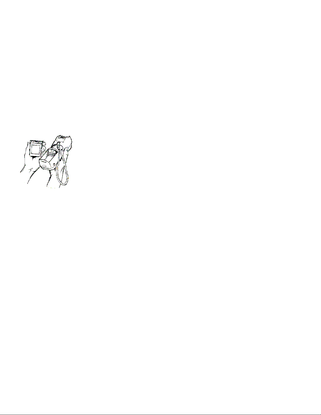
The patented shape allows true, one-handed operation and fits either hand
comfortably. Built to last, the Dolphin’s ruggedly built case houses a 386
microprocessor and DOS operating system that is easily programmable with standard
programming tools like Microsoft Visual C/C++, Borland C/C++, Visual Basic or
RF Simplicity.
device known worldwide for its ergonomic shape, light weight, versatility and
single-handed data collection features.
Dolphin is one of the most durable devices available, and is designed to withstand
repeated five-foot drops onto a concrete floor. It also resists extreme temperatures,
humidity levels and dust conditions.
The Dolphin’s basic features include long-lasting Nickel Metal Hydride (NiMH)
batteries, a large, easy-to-read 8 line x 20 character backlit display that can display text
or graphics, a natural scan and viewing angle, and two keypad options. The multiple
configurations available for the Dolphin 7200 make it one of the most versatile
terminals in the automatic data collection industry. The terminal may be equipped with
a scan engine capable of reading all standard bar code symbologies. Dolphin 7200 is
also available with the IMAGETEAM ™ 4250 Image Engine, a low power, highresolution digital image engine for omni-directional and auto-discrimination reading
and decoding of linear barcodes, stacked linear (PDF417) and 2D matrix codes. The
image engine functions like a digital camera and also provides OCR (Optical Character
Recognition) functionality. Dolphin hand held computer also is available with an
Button reader. The Dolphin 7200 RS-232 terminal features a micro-DB9 RS-232 for
i
serial data input/output and charging in addition to the infrared port. The Dolphin
Wand product package is a non-scan Dolphin 7200 RS-232 and a SCANTEAM 6180
bar code wand reader/decoder. The Dolphin 7200 RF terminal may be equipped with
an 802.11b or WLIF 2.4 GHz radio for real-time data collection applications.
Load up the Dolphin with your custom software application and the ultimate data
collection solution for your business fits in the palm of your hand.
7
Page 8

Safety
The Dolphin 7200 handheld computer/bar code scanner meets or exceeds the
requirements of all applicable standards organizations for safe operation. However, as
with any electrical equipment, the best way to ensure safe operation is to know the
possible risks.
The following safety guidelines are designed to protect both you and others around
you. Please read them carefully before using your Dolphin.
Required Safety Labels
Dolphin 7200 hand held computers use a low power Visible Laser to scan bar codes.
Short-term exposure to CDRH Class II laser light is not known to be harmful. As with
any bright light source, such as the sun, you should avoid direct eye exposure. The
following are required safety labels, as they should appear on the back panel of the
Dolphin:
Figure 1 Required Safety Labels for Dolphin 7200 laser-
8
equipped batch terminals
Page 9

Label for WLIF radio-equipped terminals
Label for 802.11b radio-equipped terminals
Figure 2 Safety Labels for Dolphin 7200 RF terminals
Figure 3 Safety Labels for Dolphin 7200 2D terminals
9
Page 10

RF Energy
The Dolphin 7200 RF™ terminal is designed to comply with the most current
applicable standards on safe levels of RF energy developed by the Institute of
Electrical and Electronics Engineers (IEEE) and the American National Standards
Institute (ANSI) and has been recommended for adoption by the Federal
Communications Commission (FCC). In addition, the Dolphin RF complies with the
specifications for an intentional radiator in Subpart C of Part 15 of the FCC’s code of
federal regulations. The Dolphin RF also complies with the European specifications
ETS 300328 (Type Test of Radio LAN to European standards) and ETS 300826
(EMC Testing of radio equipment).
Statement of Agency Compliance
The Dolphin Batch and Dolphin RF terminals both comply with part 15 of the FCC
Rules. Operation is subject to the following two conditions:
1. Devices may not cause harmful interference.
2. Devices must accept any interference received, including interference that may
cause undesired operation.
FCC Class A Compliance Statement
This equipment has been tested and found to comply with the limits for a Class A
digital device pursuant to part 15 of the FCC Rules. These limits are designed to
provide reasonable protection against harmful interference in a residential installation.
This equipment generates, uses, and can radiate radio frequency energy and, if not
installed and used in accordance with the instructions, may cause harmful interference
to radio communications. However, there is no guarantee that interference will not
occur in a particular installation. If this equipment does cause harmful interference to
radio or television reception, which can be determined by turning the equipment off
and on, the user is encouraged to try to correct the interference by one or more of the
following measures:
• Reorient or relocate the receiving antenna.
• Increase the separation between the equipment and receiver.
• Connect the equipment into an outlet on a circuit different from that to which
the receiver is connected.
• Consult the dealer or an experienced radio or television technician for help.
Caution: Any changes or modifications made to this device that are not expressly approved by Hand Held Products may
void the user’s authority to operate the equipment.
10
Page 11

Canadian Notice
This equipment does not exceed the Class A limits for radio noise emissions as
described in the Radio Interference Regulations of the Canadian Department of
Communications.
Le present appareil numerique n’emet pas de bruits radioelectriques depassant les
limites applicables aux appareils numeriques de la classe A prescrites dans le Reglement
sur le brouillage radioelectrique edicte par le ministere des Communications du
Canada.
CDRH Laser Safety Statement: 7200 Batch and RF
Laser Models
This product complies with US DHHS 21 CFR J Part 1040.10. This product is a
CLASS II LASER PRODUCT with a maximum output of 1.0 mW at 670 nanometers
and continuous wave.
EN 60825-1 Laser Safety Statement
This product is classified as a CLASS 2 LASER PRODUCT with a maximum output
of 9.0 mW at 670 nanometers per EN 60825-1:1994, Issue 2, June 1997.
R&TTE Directive: 7200 802.11 Model
The Dolphin 7200 RF is in conformity with all essential requirements of the R&TTE
Directive (1999/5/EC). This equipment has been assessed to the following standards:
ETS 300 328 ETS 300 826 (November, 1997); EN 60950: 1992, Incl Amdt 1-4, 11.
This product is marked with signifying conformity with Class II
product requirements specified in the R&TTE Directive.
The equipment is intended for use throughout the European Community, but its
authorization for use in France is restricted as follows: PAN European Frequency
Range: 2.402 - 2.480 GHz; Restricted Frequency Range for use in France: 2.448 -
2.480 GHz.
11
Page 12

R&TTE Directive: 7200 Proxim Model
The Dolphin 7200 RF is in conformity with all essential requirements of the R&TTE
Directive (1999/5/EC). This equipment has been assessed to the following standards:
ETS 300 328 ETS 300 826 (November, 1997); EN 60950: 1992, Incl Amdt 1-4, 11.
This product is marked with signifying conformity with Class II product
requirements specified in the R&TTE Directive.
The equipment is intended for use throughout the European Community, but its
authorization for use in France is restricted as follows: PAN European Frequency
Range: 2.402 - 2.480 GHz; Restricted Frequency Range for use in France: 2.448 -
2.480 GHz.
12
Page 13

Regulatory and Safety Agency Approvals
Parameter Specification
U.S.A.
Canada
Europe
Others
RF Approvals
U.S.A.
Canada
Europe
FCC Part 15, Class A
IEC 0003
EN 55022 (CISPR22) Class A
ETS 300 826 Type Certified
EMC 89/336/EEC
EN 50082-1:1997, EN55024
FCC Part 15.247 Certified
RSS 210 Certified
ETS 300 328 Certified
The CE mark on the product indicates that the system has been tested to and
conforms with the provisions noted within the 89/336/EEC Electromagnetic
Compatibility Directive and the 73/23/EEC Low Voltage Directive.
For further information please contact,
Hand Held Products (UK) Ltd.
1st Floor
Dallam Court Dallam Lane
Warrington, Cheshire WA2 7LT
England
Hand Held Products shall not be liable for use of our product with equipment (i.e.,
power supplies, personal computers, etc.) that is not CE marked and does not
comply with the Low Voltage Directive.
Interference
Pacemakers, Hearing Aids and Other Electrically Powered
Devices
Most manufacturers of medical devices adhere to the IEC 601-1-2 standard. This
standard requires devices to operate properly in an EM Field with a strength of 3V/m
over a frequency range of 26 to 1000MHz.
The maximum allowable field strength emitted by the Dolphin is 0.3V/m according to
Subpart B of Part 1 of the FCC rules. Therefore, the Dolphin RF will have no effect
on medical devices that meet the IEC specification.
13
Page 14
Microwaves
The radio in the Dolphin RF terminal operates on the same frequency band as a
microwave oven. Therefore, if you use a microwave within range of the Dolphin RF
terminal you may notice performance degradation in your wireless network. However,
both your microwave and your wireless network will continue to function.
The Dolphin Batch terminal does not contain a radio, and therefore, is not affected by
microwave ovens.
Batteries
•
Use only the battery supplied with your Dolphin or a replacement battery
supplied, recommended, or approved by HHP.
• Replace a defective battery immediately as it could damage the Dolphin
terminal.
• Never throw a used battery in the trash. It contains heavy metals and should
be recycled according to local guidelines.
• Don’t short-circuit a battery or throw it into a fire. It can explode and cause
severe personal injury.
• Excessive discharge damages a battery. Recharge the battery when your
Dolphin indicates low battery power.
• Although your battery can be recharged many times, it will eventually be
depleted. Replace it after the recommended usage period (about 500 charge
cycles for the 1500 mAh NiMH battery) or if the battery does not hold a
charge.
• If you are not sure the battery or charger is working properly, please send it to
HHP or an authorized HHP service center, for inspection.
The Dolphin handheld computer/bar code scanner meets or exceeds all applicable
standards and has been manufactured to the highest level of quality.
Care and Cleaning of the Dolphin
When needed, clean the laser engine window and the LCD display with a clean nonabrasive, lint-free cloth.
14
Page 15

Chapter 1 Getting Started
Summarizes the Dolphin’s features, functions and accessories and getting it
started for the first time.
15
Page 16

CHAPTER 1 GETTING STARTED
About the Dolphin 7200 Handheld Computer
The Dolphin is a handheld computer and imager/bar code scanner designed for easy,
single-handed data collection. It has a 386 33 MHz microprocessor that runs with GSDOS and is PC-compatible.
Accessories for the Dolphin
The Dolphin 7200 is part of a data collection system that includes accessories
specifically designed for vehicle, desktop and hub operations. Accessories available
include serial and networkable communications/charging cradles, serial
communications/charging cables, desktop “gang chargers” and vehicle mounted
charging/communication cradles.
You can use these accessories with the Dolphin:
Dolphin HomeBase Dolphin terminal charging, one-slot auxiliary battery charging and
communication station, includes power adapter.
Dolphin HomeBase power adapter Replacement power adapter for
Dolphin HomeBase. Note: Use only power adapters approved for use
by Hand Held Products. Failure to do so may result in improper
operation or damage to the unit.
10 Slot Battery Charger for Dolphin Charges and reconditions 10 batteries in under
four hours. Supports 90-264V.
VehicleBase Vehicle Kit for Dolphin Battery charging
and communications cradle providing connectivity to
any serial device including printers, radio modems,
GPS, on-board computers and vehicle monitoring
systems.
Wrist Strap for Dolphin A convenient way to carry
the Dolphin. (Note: Lanyard ring for attaching strap not
available with Dolphin 7200 RF or Dolphin 7200 RS-232.)
Holster Another convenient way to carry the Dolphin. Available in leather or
cordura, a rugged synthetic fabric.
NiMH Battery Pack Nickel Metal Hydride (NiMH) 3.6V rechargeable
battery for the Dolphin.
Communication/Charging Cable for Dolphin 7200 RS-232 Connects the
Dolphin 7200 RS-232 terminal directly to host computer using micro-DB9 to DB9
serial cable, and recharges the battery using the Universal Power Adapter PS9U-11.
16
Page 17

CHAPTER 1 GETTING STARTED
SCANTEAM 6180 Bar Code Wand Reader/Decoder connects to the Dolphin 7200
through the terminal’s Micro-DB9 RS-232 port. For use only with non-scan Dolphin
7200 RS-232 terminal as part of Dolphin 7200 Wand product package.
6’ RS-232 Serial Cable Connects HomeBase to your desktop PC.
NOTE
Use your Dolphin only
with accessories supplied,
recommended or
approved by Hand Held
Products, Inc. Use of
non-approved accessories
can be dangerous and will
invalidate any warranty or
liability claims.
Contact your Value-Added Reseller for more information. For details about how to
install or use any of these accessories, refer to the documentation provided with the
product.
Dolphin 7200 Models and Options
Hand Held Product’s family of Dolphin 7200 handheld portable data collection
terminals includes these models:
The Dolphin® 7200 Batch terminal is a DOS programmable handheld computer/bar
code scanner with a unique, ergonomic shape designed for single-handed use. The
basic terminal has 2MB RAM and 8MB FLASH EEPROM memory. It also features
an IrDA infrared transceiver for data communications.
The Dolphin® 7200 with iButton Reader handheld computer integrates the basic
functionality of the Dolphin Batch terminal with iButton™ technology that allows the
terminal to read and write data from and to iButtons. The iButton reader is a function
and feature extension of the Batch terminal.
The Dolphin® 7200 RF terminal integrates the basic functionality of
the Batch terminal with a 2.4GHz RF interface that allows the
terminal to communicate with a host computer via a wireless local
area network (WLAN). There are two options for this terminal: an
802.11b direct sequence spread spectrum radio or a WLIF frequency
hopping spread spectrum radio.
Dolphin® 7200 RS-232 terminal is identical to the Dolphin 7200 Batch terminal
The
except that it features a micro-DB9 RS-232 port for serial data input/output and
charging.
The
Dolphin® 7200 Wand is a product package consisting of a non-scan Dolphin 7200
RS-232 terminal loaded with factory-installed drivers and a SCANTEAM® 6180 bar
code wand reader/decoder.
Dolphin® 7200 2D terminal uses IQ Imaging™, a suite of features that offer
The
increased productivity when reading all major linear, stacked linear (PDF417), and
matrix bar code symbologies, OCR fonts, and performing image capture. It features
the IMAGETEAM™ 4250 Image Engine, a low power, high-resolution digital image
engine for omni-directional and auto-discrimination reading and decoding.
17
Page 18

CHAPTER 1 GETTING STARTED
These following options are available for the Dolphin 7200 terminal:
.
Dolphin Batch Dolphin RF
36-key alphanumeric keypad or 20-key
numeric keypad with shifted alpha
characters
Standard High Performance, Long-Range
or High Density scan engines
2 MB RAM with 8 MB non-volatile
FLASH memory (expandable to 16 MB
36-key alphanumeric keypad or 20-key
numeric keypad with shifted alpha
characters
Standard High Performance, Long-Range
or High Density scan engines
2 MB RAM with 8 MB non-volatile
FLASH memory
on Dolphin 7200 Batch only)
No scan engine (manual entry only) No scan engine (manual entry only)
iButton reader Terminal emulation software and keypad
overlays for IBM 3270, IBM 5250 and
DEC VT220 emulation.
Integrated image engine 802.11b direct sequence spread spectrum
radio or WLIF frequency hopping spread
spectrum radio
Micro-DB9 RS-232 serial port
Bar Code Symbologies Supported
The Dolphin 7200 series of terminals supports the following 1D linear codes:
Code 3 of 9, Interleaved 2 of 5, Code 11, MSI, UPC A, UPC EO, UPC EI,
EAN/EAN13, Codabar, Code 128, Code 93, UPC
The Dolphin 7200 Wand (Non-scan Dolphin 7200 RS-232 and a SCANTEAM 6180
bar code wand reader/decoder) product package supports the following 1D linear
codes:
Code 39, Interleaved 2 of 5, Code 2 of 5, UPC-E/A, MSI, EAN/JAN, Codabar, Code
128, Code 11 and Code 93.
In addition, the Dolphin 7200 2D terminal supports the following:
2D codes:
PDF417, microPDF, Maxicode, Datamatrix, Aztec, QR Code, Code 49
Composite codes:
RSS-14, CODABLOCK, AZTEC MESA
18
Page 19

NOTE
NOTE
Be sure to keep the
Be sure to keep the
original carton and
original carton and
packaging in the event
packaging in the event
that the Dolphin
that the Dolphin
terminal or Dolphin
terminal or Dolphin
HomeBase™ should
HomeBase™ should
need to be returned for
need to be returned for
service.
service.
CHAPTER 1 GETTING STARTED
OCR codes (Optical Character Recognition):
OCR A and OCR B
Postal Codes:
Postnet and most international 4 state codes, PLANET CODE, BPO 4 STATE,
CANADIAN 4 STATE, DUTCH POSTAL, AUSTRALIAN 4 STATE, JAPANESE
POSTAL
Using Dolphin for the First Time
This section will show you how to:
1. Be sure that you’ve received all items included with your Dolphin order
2. Charge the battery
3. Turn the Dolphin on and off
4. Set the date and time
1 Checking Your Package
If you ordered a Dolphin 7200 Batch, iButton, 2D or RF terminal, inspect the package
to see that the following standard items and accessories (if ordered) are included:
• Dolphin 7200 hand held computer
• Battery (1500 mAh, Nickel Metal Hydride (NiMH)
• Dolphin 7200 HomeBase
• AC-DC Power Adapter for Dolphin HomeBase
If you ordered a Dolphin 7200 RS-232 terminal, inspect the package to see that the
following standard items and accessories (if ordered) are included:
• Dolphin 7200 RS-232 hand held computer
• Battery (1500 mAh, Nickel Metal Hydride (NiMH)
• Dolphin 7200 RS-232 Communication/Charging Cable
• AC-DC Universal Power Adapter
19
Page 20

NOTE
Be sure to keep the
original carton and
packaging in the event
that the Dolphin
terminal or Dolphin
HomeBase™ should
need to be returned for
service.
CHAPTER 1 GETTING STARTED
If you ordered a Dolphin 7200 Wand (non-scan Dolphin 7200 RS-232 terminal and
SCANTEAM 6180 bar code wand reader/decoder), inspect the package to see that
the following standard items and accessories (if ordered) are included:
• Dolphin 7200 RS-232 non-scan hand held computer
• SCANTEAM 6180 bar code wand reader/decoder
• Battery (1500 mAh, Nickel Metal Hydride (NiMH)
• Dolphin 7200 RS-232 Communication/Charging Cable
• AC-DC Universal Power Adapter
20
Page 21

CHAPTER 1 GETTING STARTED
NOTE
For maximum
battery life, Hand
Held Products
recommends that
you deep-cycle
(service) the battery
twice before initial
use and then, once a
month thereafter.
2 Charging the Battery
CAUTION: Use only 3.6V battery packs provided by Hand Held Products.
The use of any other battery pack in the Dolphin terminal will void your
warranty and may result in damage to the Dolphin terminal or battery.
The terminal’s NiMH battery is not conditioned at the factory and is shipped
discharged of all power and inserted in the Dolphin terminal. For maximum battery
life, Hand Held Products recommends that you deep-cycle the battery twice before
initial use.
WARNING: Although the Dolphin 7200 terminal is received with the battery inserted, it is
NOT ready for charging and/or deep-cycling. Remove the plastic insulator located between the
terminal and battery connectors. Failure to remove the insulator may result in damages to the terminal.
To deep-cycle, insert the battery into the HomeBase auxiliary battery well. Then, push
and hold the Service Aux Batt button for at least four seconds.
You may also use the CycleBat software utility to deep-cycle the battery. This utility is
available for download from the Partners Area of http://www.hhp.com/
.
If you have a Dolphin 7200 RS-232 terminal and are using the
communication/charging cable instead of a HomeBase to charge the battery, charge
the terminal for 24 hours before initial use.
After deep cycling the battery, you may charge the battery using one of these methods:
• Place the battery in the auxiliary battery well on the Dolphin HomeBase™.
Time to Charge: 3 hours
• Place the battery in the 10-slot Dolphin multiple battery charger. Time to
Charge: 3 hours
• Install the battery in the Dolphin, place the Dolphin in the HomeBase and
connect the HomeBase to an external power source. Time to Charge: 5 ½
hours
• Plug the micro-DB9 end of the communication/charging cable into Dolphin
7200 RS-232 terminal’s RS-232 port and connect to an external power source.
Time to Charge: 5 ½ hours
21
Page 22

CHAPTER 1 GETTING STARTED
For help, see the chapter on the Dolphin. To learn more about managing the
terminal’s battery power, see “Maintaining the Dolphin’s Batteries” in Chapter 2.
Inserting the Battery Pack
1. Hold the Dolphin with the front panel (keypad) facing down.
2. Insert the end without the locking tab into the bottom of the battery opening and
snap the battery into place with a hinging motion. The battery case serves as the
back cover of the Dolphin.
Removing the Battery Pack
1. Hold the Dolphin with the front panel (keypad) facing down.
Ð
Ð
2. Push the locking tab on the battery pack down and pull the battery out from the
Dolphin terminal with a hinging motion.
Ó
Ó
Figure 2 Inserting and Removing the Battery
22
Page 23

CHAPTER 1 GETTING STARTED
3 Turning the Dolphin On And Off
Turning On the Dolphin
1. Install the charged battery pack in the Dolphin.
2. Hold the Dolphin in the palm of your hand so that you can press the ON/SCAN
key easily with your thumb.
3. Press the ON/SCAN key to turn the Dolphin on. Your Dolphin will boot up just
like a desktop PC and the title screen for the HHP Demo Application will appear
on the display.
If the title screen does not appear on the display of your Dolphin, the HHP Demo
Application has been removed from your terminal. Therefore, you will see a DOS
prompt on the screen. Example: C:\ or A:\ .
Note: If using the Dolphin for first time or if the terminal has been without a battery pack for more
than 30 minutes and you are now inserting a battery, you may receive a CMOS error when the
terminal boots up. Don’t worry, the terminal is OK. This simply means that the internal back-up
battery needs to be recharged and the date and time need to be reset. To recharge the internal backup
battery and reset the date and time, insert a fully charged battery in the Dolphin and then use the DOS
date and time function to set the correct date and time. The internal back-up battery requires a
minimum of 5 hours of charging time in order to perform and maintain the system as described on page
30.
Turning the Dolphin Off
The Dolphin is never actually turned off. To conserve power, the Dolphin goes into
“sleep mode” when it is inactive for a programmed period of time as defined by your
application. The screen is blank when the Dolphin is in “sleep mode.”
4 Setting the Date and Time
Use the DOS date and time function to set the correct date and time for your Dolphin
terminal.
To set the date on an alphanumeric Dolphin:
1. Enter <DATE> at the Dolphin’s DOS prompt.
2. Press NUM LOCK to put the Dolphin in numeric mode.
3. Enter the new date <mm-dd-yyyy>.
4. Press <ENTER>.
23
Page 24

CHAPTER 1 GETTING STARTED
To set the date on a numeric Dolphin:
1. Press <SHIFT> to put the Dolphin in alpha mode.
2. Enter <DATE> at the Dolphin’s DOS prompt. See the section called Using the
Numeric Keypad in Chapter 2 for more information.
3. Press <SHIFT> to put the Dolphin back in numeric mode.
4. Enter the new date <mm-dd-yy>.
5. Press <ENTER>.
To enter the new time, enter <TIME> at the Dolphin’s DOS prompt instead of
<DATE> and follow the directions for the Dolphin model you are using.
24
Page 25

Chapter 2 Dolphin Basics
Describes system features and explains how to use the Dolphin’s keypad,
display, batteries, drives and scanner.
25
Page 26

NOTE
Drive C is an image of
the A drive and not a
physical drive.
CHAPTER 2 DOLPHIN BASICS
System Features
CPU
The Dolphin’s computing power is provided by a highly integrated AMD ELAN
SC310 386SX 33 MHz microprocessor.
Disk Drives
The Dolphin contains two disk drives that provide storage for system files,
applications, and data. A third drive is also present if you purchase the FLASH
expansion option.
Drive A
Drive A contains a 120K executable FLASH EEPROM to store system utilities and to
initialize the boot process. This drive is read-only and is not usable by the
developer/end-user.
Drive C
Drive C is an 8MB FLASH virtual hard drive used for program and data storage.
Drive D
If you add the expanded memory module to your Dolphin Batch terminal, it will
appear as Drive D. Eight (8)MB of additional FLASH memory can be added via the
FLASH expansion module. Note: This option is only available for the Dolphin batch and
Dolphn iButton terminals.
Front Panel Physical Features
This section describes features on the Dolphin’s front panel. The alphanumeric and
numeric Dolphins have identical back panels.
Light Emitting Diodes (LED)
The red LED located at the upper right corner of the LCD display is labeled ‘SCAN’.
This LED illuminates when the user presses the ON/KEY key and activates the scan
engine.
The green LED located at the upper left corner of the LCD display is labeled
‘DECODE.’ This LED illuminates when the bar code software successfully decodes a
bar code. Both LEDs are software programmable.
26
Page 27

CHAPTER 2 DOLPHIN BASICS
Liquid Crystal Display (LCD)
The alphanumeric, scrollable LCD consists of nine rows with 20 character positions
per row and 119 x 73 graphics pixels, which are software addressable. The
electroluminescent backlight allows you to view the display in low light conditions. To
conserve power, the backlight is automatically turned off after 30 seconds. The on/off
function and contrast is software programmable.
Note: The ninth row is used for system icons and application-defined icons.
Speaker
The Dolphin Batch terminal’s internal speaker emits a sound level of 80dB at 10 cm.
The sound level for the Dolphin RF terminal’s external speaker is 90dB at 10 cm.
RF Antenna
The Dolphin RF terminal’s 1.36 inch (34.5 mm) antenna is a unity gain, helicallyloaded, monopole antenna.
27
Page 28

CHAPTER 2 DOLPHIN BASICS
y
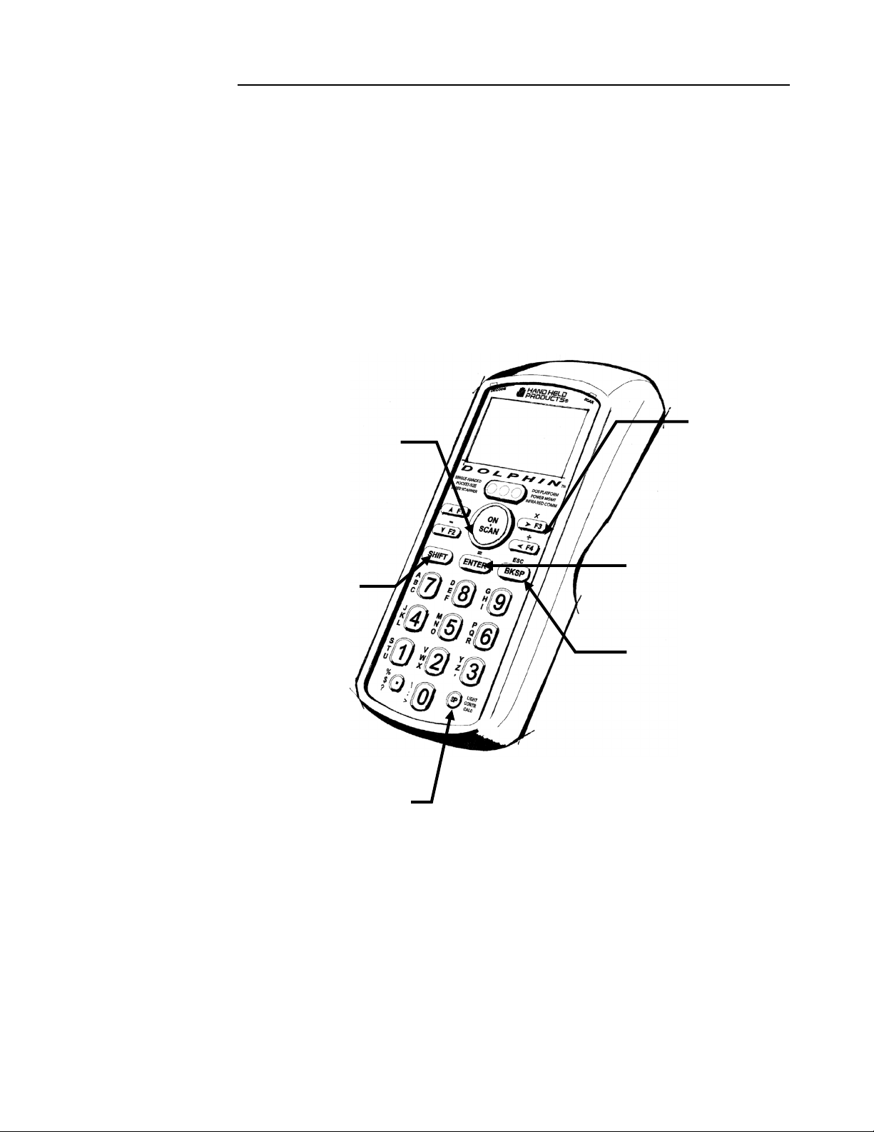
Using the Alphanumeric Keypad
The Dolphin’s alphanumeric, splash-resistant keypad has 36 epoxy coated keys. The
keyboard’s yellow background enhances the readability of the numeric and special
character keys.
The Dolphin’s ON/SCAN key “wakes” the
terminal from sleep mode. Its position also
allows convenient one-handed bar code
scanning.
The SHIFT key
toggles the Dolphin
from alpha to
numeric mode and
back and, in
combination with
other keys, allows
you to enter special
characters.
The F1, F2, F3 and
F4 keys are userdefinable function
keys and may be
programmed for a
variety of functions.
The ENTER key
confirms data
entry.
The NUM LOCK
key toggles between
the alphabetic and
numeric modes.
Figure 3 Dolphin Alphanumeric Keypad
The LIGHT key
toggles the LCD
backlight on
and off.
The BKSP key moves you
to move the cursor back
one space each time the
ke
is pressed.
28
Page 29

CHAPTER 2 DOLPHIN BASICS
Key Combinations For Keypad Functions and Special
Characters
Use the key combinations listed below to access certain keypad functions or to use
special characters that are not defined on the Dolphin keypad.
Key Combination
Function/Special
ESC (SHIFT + BKSP)
The ESC function
performs a cancel action.
SPC (SHIFT + U)
The SPC function
moves the cursor
forward one space at a
time.
CLR (SHIFT + A)
The CLR function erases
the line of data just
entered, if the ENTER
key has not yet been
pressed.
SHIFT + F
SHIFT + K
SHIFT + P
SHIFT + V
SHIFT + W
SHIFT + X
SHIFT + Y
SHIFT + Z
SHIFT + E
SHIFT + J
SHIFT + LIGHT
Figure 4 Key Combinations for Alphanumeric Keypad
Changes Contrast
Character
#
@
&
$
%
!
\
:
*
/
29
Page 30
CHAPTER 2 DOLPHIN BASICS
Using the Numeric Keypad
The Dolphin’s numeric, splash-resistant keypad has 20 epoxy coated keys. The large,
amber-color keys are large, easy-to-read, and comfortably spaced to help prevent errors
in data entry. Digits can be entered without using the shift key.
Though designed primarily for numeric data entry, you can use the SHIFT key to
switch between numeric and alpha modes or to use special characters.
The Dolphin’s
ON/SCAN key
“wakes” the
terminal from sleep
mode. Its position
also allows
convenient onehanded bar code
scanning.
The SHIFT key
toggles the Dolphin
from numeric to
alpha mode and
back. You can also
enter special
characters.
The F1, F2, F3 and
F4 keys are userdefinable function
keys. These keys
may be
programmed for a
variety of functions.
The ENTER key
confirms data
entry.
The BKSP key
moves the cursor
back one space each
time the key is
pressed.
The SP key moves
the cursor forward
one space at a time.
Figure 5 Dolphin Numeric Keypad
30
Page 31

CHAPTER 2 DOLPHIN BASICS
Key Combinations For Keypad Functions and Special
Characters
Key Combination
ESC (SHIFT + BKSP)
LIGHT (SHIFT + SP)
CONTR (SHIFT + SP+SP)
CALC
Function
The ESC function performs a cancel
action.
This action toggles the LCD backlight
on and off. Press the SHIFT key to
put the Dolphin in alpha mode and
press the SP key once.
The CONTR function adjusts the
LCD contrast. Press the SHIFT key
to put the Dolphin in alpha mode and
press the SP key twice. Use the F1
and F2 keys to adjust the contrast up
or down. When finished, press the
BKSP key.
This function is undefined. However,
it can be programmed by a custom
application to load a calculator utility.
Figure 6 Key Combinations and What They Do
Numeric Keypad
Entering Alpha and Special Characters
1. Press the SHIFT key to switch the numeric keypad to alpha mode. This is
indicated by the <ABC> symbol indicated on the LCD. Each numeric key, as
well as the “.” Key has three letters or symbols listed beside it.
2. To display the first letter or symbol next to a key, press the numeric key once.
3. To display the second letter/symbol, press the key next to the desired
letter/symbol twice within one second.
31
Page 32

CHAPTER 2 DOLPHIN BASICS
4. To display the third letter/symbol, press the key next to the desired letter/symbol
three times within one second.
For example, to enter a letter “G” into the Dolphin terminal, press the SHIFT key to
put the Dolphin in alpha mode. Press the “9” key once and the letter “G” will be
entered.
To enter a “T” into the Dolphin terminal, press the SHIFT key to put the Dolphin in
alpha mode. Press the “1” key twice and the letter “T” will be entered.
Display Symbols
Here is a list of the symbols that can appear on the LCD display of your Dolphin and
their meanings.
Battery Charge
Battery charging symbol blinks while main battery in the Dolphin
terminal is charging in the Dolphin 7200 HomeBase. Located in
lower left-hand corner of the LCD.
NOTE
The battery charge
level symbol is only
an estimate of the
remaining battery
life.
Battery charging symbol blinks while the main battery in the Dolphin
terminal is discharging when using the battery deep-cycling utility
program
Battery charging symbol shown above switches from a blinking arrow
to a blinking check when the unit has completed charging in the
HomeBase.
Indicates charge level of the Dolphin terminal’s main battery when
the terminal is in use. The charge symbol decreases in size as the
charge level drops. Located in lower left-hand corner of the LCD.
When this symbol is blinking, the battery’s charge is critically low and you should
recharge it as soon as possible.
For information on battery capacity and charging, see the section on Maintaining the
Dolphin’s Batteries later in this chapter.
Keyboard Mode
These symbols indicate which mode is operational on the keyboard and are located
next to the battery charge indicator. Use the SHIFT key to toggle between numeric to
alpha mode on Dolphin.
32
Page 33

CHAPTER 2 DOLPHIN BASICS
Alpha mode -- alphabetic characters are active
Numeric mode -- numeric characters are active
33
Page 34

CHAPTER 2 DOLPHIN BASICS
D
D
Back Panel Features
This section describes features on the Dolphin’s back panel. The alphanumeric and
numeric Dolphins have identical back panels.
Laser/Image
EngineWindow
Battery Well
Micro-DB9 RS-232
(Dolphin 7200 RS-
232) or Lanyard
Eyelet
(not available on
olphin RF or
olphin 2D)
Reset Switch
Battery Charging
Contacts
Infrared
Communications
Port
Figure 7 Dolphin Back Panel
34
Page 35

CHAPTER 2 DOLPHIN BASICS
Laser Engine
The Dolphin 7200 is currently available with four scanning options:
• Standard range
• Long range
• High density scanning
• No scan engine
The laser engine converts reflected light into a digital pattern that represents the bar
code data. A clear window covers the laser engine to protect it from dust and dirt.
Image Engine
The Dolphin 7200 2D terminal is available with the following imaging options:
• Standard image engine: scans 2 to 9 in. (5 to 23 cm)
• High-Density: scans 2 to 4 in. (5 to 12 cm)
• LX image engine: scans 2 to 15 in. (5 to 38 cm) on low density bar codes
NOTE
Under normal
circumstances, you
should never need to
reset your Dolphin
terminal.
Lanyard Eyelet for Optional Wrist Strap
This feature allows a strap to be attached to the Dolphin terminal so that it can be
conveniently secured around the wrist or hooked on to a belt. Not available on the
Dolphin 7200 RF, the Dolphin 7200 2D or the Dolphin
7200 RS-232 terminals.
Battery Well
The Battery Well is a recessed area on the back of the
Dolphin that holds the 3.6V battery pack.
Reset Switch
The Reset Switch is located inside the Dolphin terminal and is accessible through a
small opening within the battery well. To reset the Dolphin, remove the label covering
the opening and press the reset switch with a small blunt object such as a paper clip.
Infrared Communications Port
The Infrared Communications Port allows the Dolphin to communicate through the
Dolphin HomeBase to a host serial device.
Battery Charging Contacts
When the Dolphin is placed in the main well of the Dolphin HomeBase, the
Dolphin’s battery pack is charged through these contacts.
35
Page 36

NOTE
Never insert the
Dolphin into the
HomeBase without the
NiMH main battery pack
inserted.
CHAPTER 2 DOLPHIN BASICS
Maintaining the Dolphin’s Batteries
CAUTION: Use only the 3.6V battery packs provided by Hand Held Products.
The use of any other battery pack in the Dolphin 7200 terminal will void your
warranty and may result in damage to the Dolphin terminal or battery.
There are two batteries in the Dolphin:
Internal NiMH Backup Battery
Located inside the Dolphin, this battery backs up the RAM and clock when the NiMH
main battery is discharged or removed from the terminal.
NiMH Battery Pack
The battery pack is the primary power source for operating the Dolphin.
Internal NiMH Backup Battery
The Dolphin’s internal backup battery prevents the terminal from being reset if you
need to remove and replace the main battery pack. The battery retains RAM data and
allows the real-time clock to remain operational for up to 30 minutes when the battery
pack is removed. If the internal back-up battery becomes discharged of power, it
requires a minimum of 5 hours of charging time in order to perform and maintain the
system as described above.
NOTE
Return the Dolphin to
an authorized service
center when the
internal battery needs
to be replaced.
The internal backup battery is charged by the Dolphin’s main battery pack. If the
terminal is left without the main battery pack for more than 30 minutes, the internal
backup battery needs to be recharged.
Note: Data and programs on Drives C and D remain safe even if the internal backup battery fails.
However, you must reset the real-time clock using the DOS Time and Date function.
Follow these guidelines to maximize the life of the Dolphin’s backup battery:
• Keep a charged NiMH battery pack in the Dolphin. The internal battery
will prematurely discharge if there is not at least a partially charged battery
in the terminal.
• Put the Dolphin in the HomeBase when the terminal is not in use.
36
Page 37

NOTE
Keep a charged
battery pack in the
Dolphin at all times to
conserve the internal
back-up battery.
CHAPTER 2 DOLPHIN BASICS
NiMH Battery Pack
The 3.6V, 1500 mAh Nickel-Metal-Hydride (NiMH) battery pack is the
primary power source for the Dolphin. Other Nickel-Metal-Hydride
batteries may be approved by Hand Held Products, Inc. to work with your
Dolphin. Contact Hand Held for more information.
The 1500 mAh NiMH battery is designed to operate in temperature range
of –10 to 50 °C (14 to 122° F). For maximum performance, charge the batteries
between 10 and 35 °C (50 and 95° F).
WARNING: Although the Dolphin 7200 terminal is received with the battery inserted, it is
NOT ready for charging and/or deep-cycling. Remove the plastic insulator located between the
terminal and battery connectors. Failure to remove the insulator may result in damages to the terminal.
Performance specifications for a fully charged 1500 mAh NiMH battery (using power
management function calls within application):
Up to 20 hours of usage in a Dolphin Batch terminal with a full battery charge
NOTE
For maximum battery
life, Hand Held
Products recommends
that you deep-cycle
(service) the battery
twice before initial use
and then, once a month
thereafter.
Up to 10 hours of usage in a Dolphin RF terminal with a full battery charge
Up to 20 hours of usage in a Dolphin 2D terminal with a full battery charge
Keep a charged battery pack in the Dolphin at all times to conserve the internal backup battery. When you remove a battery pack, insert another battery pack in the
Dolphin. The internal battery will prematurely discharge if there is not at least a
partially charged battery in the terminal.
Servicing the Battery Pack
For maximum battery life, Hand Held Products recommends that you deep-cycle the
battery twice before initial use. It is also recommended that you service, or calibrate
the battery once per month. To deep cycle, insert the battery into the HomeBase
auxiliary battery well. Then, push and hold the Service Aux Batt button for at least 4
seconds. For more information, see the section on the Service Aux Batt feature of the
HomeBase in Chapter 7.
You may also deep cycle the battery using the CycleBat battery utility conditioning
software which is available from the Partners area of the Hand Held Products website,
http://www.hhp.com/
. More information on this utility is available from the help file
that comes with the software.
37
Page 38

CHAPTER 2 DOLPHIN BASICS
Charging the Battery Pack
You can recharge an individual battery pack using the auxiliary battery well of the
Dolphin HomeBase, or the Dolphin 10-Slot Multiple Battery Charger. Both
accessories use a charging method that senses when the battery
pack is fully charged and then drops to a trickle charge to keep
the battery pack at full capacity.
For more details, see the section on Charging Batteries in the
HomeBase in Chapter 7.
Storing Batteries
To maintain top performance from batteries, follow the guidelines below when storing
them:
• Avoid storing batteries outside of the specified range of -4 to 104° F
(-20 to 40°C) or in extremely high humidity.
• For prolonged storage, do not keep batteries stored in the terminal.
• During long-term storage, battery deactivation may tend to occur which
may cause charging to stop early during recharging after storage.
Charging and discharging the battery several times can handle this issue.
Also, the first charging after prolonged storage may yield a lower than
normal capacity. While this will vary depending on the storage
conditions, charging and discharging the battery several times will
almost completely restore capacity.
38
Page 39

Chapter 3 Dolphin® 7200 RF
Handheld Computer
39
Page 40

CHAPTER 3 DOLPHIN 7200 RF HANDHELD COMPUTER
About the Dolphin 7200 RF Handheld Computer
The Dolphin 7200 RF® terminal integrates the basic functionality of the Batch terminal
with an 802.11b or a WLIF™ interface that allows the terminal to communicate with a
host computer via a wireless local area network (WLAN). Both radio options operate
in the 2.4 GHz frequency band. Terminal emulation software and keypad overlays for
IBM 3270, IBM 5250 and DEC VT100/220 emulation are available for both radio
options. The terminal’s DOS compatible 386 microprocessor is easy to program and
developers can create wireless applications linked to a host PC, using RF Simplicity®
and MS Visual Basic™.
Refer to Chapters 1 and 2 in this manual for more on basic operation of the Dolphin
terminal and accessories available.
802.11b-Compliant Dolphin 7200 RF Terminal
The 802.11b-compliant Dolphin 7200 RF incorporates a Cisco® 802.11b Micro-ISA
radio. The radio uses direct sequence spread spectrum (DSSS) technology, which
spreads its signal continuously over a wide frequency band, and provides an Ethernetlike data rate of up to 11 megabits per second. The radio may also provide up to 128bit Wired Equivalent Privacy (WEP) encryption. WEP is used to encrypt and decrypt
data signals transmitted between Wireless LAN (WLAN) devices. It is an optional
security encryption mechanism defined within the 802.11 standard that makes a
wireless LAN link as secure as a traditional wired link. The optional WEP security
mechanism is available with 128-bit or 40-bit encryption.
Dolphin 7200 RF is interoperable with other 802.11b compliant products to allow
network expansion as needed. It can be connected to other devices, such as printers
and PCs via PC-card adapters.
40
Page 41

CHAPTER 3 DOLPHIN 7200 RF HANDHELD COMPUTER
Configuring Your 802.11b- Compliant Dolphin 7200
RF Terminal
The Dolphin 7200 RF Utilities program provides basic functions required to prepare
your terminals for use. The program also includes a Scan Demo, Help, and an
Inventory Control demo.
When you cold-boot or reset the terminal, the title screen shown below appears. Press
the <ENTER> key to continue.
Dolphin 7200 RF Title Screen
Main Menu
The Dolphin 7200 RF Main Menu shown appears after the title screen:
Dolphin 7200 RF Main Menu
41
Page 42

CHAPTER 3 DOLPHIN 7200 RF HANDHELD COMPUTER
F1-Scan
F1-Scan Menu
This option demonstrates how the Dolphin 7200 RF terminal scans bar codes. Press
F1 to configure the terminal to read linear barcodes. Follow the directions on the
screen to set-up which bar codes you want the terminal to read. Once the terminal is
configured, press <ESC> and then the <ON/SCAN> Button to scan a bar code.
F2-Help
F2-Help Menu
This option is an online help file with general information about using the Dolphin
7200 RF terminal, battery maintenance, contacting Hand Held Products, specifications
and navigating through the help file.
42
Page 43

CHAPTER 3 DOLPHIN 7200 RF HANDHELD COMPUTER
F3-HHP Demo
F3-HHP Demo
The HHP Demo is a sample inventory control program.
F4-Utilities Menu
F4-Utility Menu
43
Page 44

CHAPTER 3 DOLPHIN 7200 RF HANDHELD COMPUTER
F1-COM Menu
F1-COM Menu
Use this menu to send and receive files when transmitting data via HomeBase or
VehicleBase to the local area network. Press <F1> to send a file. Press <F2> to
receive a file. For more information on sending or receiving files with the Dolphin
7200 HomeBase, see the section on Setting Up For Communications in Chapter 7. See
Chapter 8 for more information on communications with the Dolphin 7200 Compact
HomeBase.
F2-System Menu
F2-System Menu
This option allows you to view system information such as version and serial numbers
about specific Dolphin 7200 RF terminals. You may also enable or disable the reboot
setting and turn the display status line on or off.
44
Page 45

CHAPTER 3 DOLPHIN 7200 RF HANDHELD COMPUTER
F3-DOS Prompt
Press <F3> to exit to the DOS prompt.
F4-RF Menu
Press <F4> and the menu below will appear. Use options from this menu to
configure the Dolphin 7200 RF for use in your wireless local area network.
F4-RF Menu
45
Page 46

CHAPTER 3 DOLPHIN 7200 RF HANDHELD COMPUTER
F1 RF Setup
To configure the terminal for use in a local area network, press <F1> and enter the
data for each of the options on the screen shown below:
RF Setup Menu
NOTE
The SSID and Subnet
Mask on the Dolphin
terminal must match the
settings on the access
point.
You cannot change the MAC address on the Dolphin terminal. Each terminal has its
own unique factory-set MAC address. The MAC address is a standardized data link
layer address that is required for every port or device that connects to a LAN. Other
devices in the network use this address to locate specific ports in the network and to
create and update routing tables and data structures.
F1 SET SSID
Press <F1> to set the SSID. This value is case sensitive. Enter a value for the SSID
option and press <ENTER>. Once the SSID is written, the Dolphin 7200 RF
terminal must be reset to activate the new SSID.
The SSID (Service Set Identifier) is a unique, case-sensitive identifier that is attached to
selected packets sent out over the radio network. Nodes associating to the access point
must use the same SSID or their association requests will be ignored. The SSID can
have up to 32 characters.
46
Page 47

CHAPTER 3 DOLPHIN 7200 RF HANDHELD COMPUTER
F2 SET NODE
NOTE
Reset the Dolphin
terminal by pressing
and releasing the
<SHIFT>,
<ON/SCAN>
and <BKSP> keys.
All three keys must be
held down and released
at the same time.
NOTE
The Dolphin need not
be reset after each
configuration change,
but can be done once
all configurations
changes have been
made.
Press F2 to set a system name for the Dolphin 7200 RF terminal. Enter a value for the
NODE option and press <ENTER>. Once the NODE is written, the Dolphin 7200
RF terminal must be reset to activate the new NODE. The name should describe the
location or principal users of the Access Point.
F3 R/W IP ADDRESS
Press F3 to enter the IP address. Enter a value for the IP Address option and press
<ENTER>. Once the IP Address is written, the Dolphin 7200 RF terminal must be
reset to activate the new IP Address.
The IP address is a 32-bit address assigned to hosts using TCP/IP. An IP address
belongs to one of five classes (A, B, C, D, or E) and is written as four octets separated
by periods (dotted decimal format). Each address consists of a network number, an
optional sub network number, and a host number.
F4 R/W SUBNET MASK
Press F4 to enter the Subnet Mask. Enter a value for the Subnet Mask option and
press <ENTER>. Once the Subnet Mask Address is written, the Dolphin 7200 RF
terminal must be reset to activate the new Subnet Mask.
The Subnet Mask is the portion of an IP address that is specified as the sub network by
the subnet mask.
47
Page 48

CHAPTER 3 DOLPHIN 7200 RF HANDHELD COMPUTER
Setting WEP Modes And Keys On The 802.11b Radio Card
This section describes how to set WEP (Wired Equivalent Privacy) modes and keys on
the Cisco® 802.11b radio card.
WEP is used to encrypt and decrypt data signals transmitted between Wireless LAN
(WLAN) devices. WEP is an optional IEEE 802.11 feature used to provide data
confidentiality that is equivalent to the confidentiality of a wired LAN that does not
employ crypto techniques to enhance privacy. WEP makes a wireless LAN link as
secure as a wired link.
The wep.bat utility is used to set WEP modes and keys for the Cisco® 802.11b radio
card. The wep.bat file uses three files:
wepdos.exe – an executable file that configures WEP values for the Cisco radio
keys.exe – an executable file that calls the functions for setting WEP values
cscpkt.ini – a configuration file for the Cisco radio
All four files are located in the Dolphin c:\rf directory that is part of the
stackcsc.exe file.
If the user will be setting WEP keys using the batch mode, the user must create a
keys.txt file using a text editor such as Notepad and then copy it to the c:\rf directory.
This file will contain the encryption keys used when operating in WEP mode. For
obvious security reasons, this file will be automatically deleted upon running the
wep.bat utility. HHP recommends that you verify that the keys.txt file has been
deleted.
Refer to the Cisco documentation for complete descriptions of the various WEP
modes. The current radio card may not support some modes.
48
Page 49

CHAPTER 3 DOLPHIN 7200 RF HANDHELD COMPUTER
Running the WEP.BAT Utility
This section describes usage and command line options for the WEP.BAT utility.
NOTE
Reset the Dolphin terminal
by pressing and releasing the
<SHIFT>, <ON/SCAN>
and <BKSP> keys.
All three keys must be held
down and released
at the same time.
Note: The WEP.BAT file must be run with the radio driver NOT loaded. Reboot the
Dolphin 7200 RF terminal with the ON/SCAN key depressed so that the driver will
not load.
WEP [BATCH] [HEX] [ASCII] [STATUS] [SELECTKEY#] [CLEARKEY#]
[OPEN] [WEPSHARED] [WEPOPEN]
WEP OPTIONS
BATCH Sets radio WEP keys using the file keys.txt .
HEX Sets radio WEP keys using a hex string
entered via the keyboard.
ASCII Sets radio WEP keys using ASCII characters
entered via the keyboard.
STATUS Displays encryption level and key lengths.
SELECTKEY # Selects operating key used during operation
with access point.
CLEARKEY # Clears operating key.
OPEN Disables WEP operation even if keys have
been set (no encryption) .
WEPSHARED Sets WEP mode to WEPSHARED. In this
mode, the Access Point sends a plain-text,
shared-key query to any device attempting
to communicate with the Access Point.
WEPOPEN (default) Sets WEP mode to WEPOPEN which
allows any device, regardless of its WEP
settings, to authenticate and then attempt to
communicate with the Access Point.
49
Page 50

CHAPTER 3 DOLPHIN 7200 RF HANDHELD COMPUTER
Example 1: To configure WEP using the batch mode, create the keys.txt file
using a text editor as shown:
Sample ASCII keys.txt file for 40-bit encryption where x is the key code:
ASCII
xxxxx
xxxxx
xxxxx
xxxxx
xxxxx
Sample HEX keys.txt file for 128-bit encryption where x is the key code:
HEX
xxxxxxxxxxxxxxxxxxxxxxxxxx
xxxxxxxxxxxxxxxxxxxxxxxxxx
xxxxxxxxxxxxxxxxxxxxxxxxxx
xxxxxxxxxxxxxxxxxxxxxxxxxx
xxxxxxxxxxxxxxxxxxxxxxxxxx
After creating the keys.txt file, copy it to the c:\rf directory and enter:
C:>\WEP BATCH
Result: The WEPOPEN operating mode is automatically set (the WEP mode can be
changed using commands shown later in this document). One of the following
messages will display on the terminal:
Need keys.exe and keys.txt (if both files are not present)
or
Error(s): Retry (if error occurred writing to radio card)
or
Done (if keys successfully set)
50
Page 51

CHAPTER 3 DOLPHIN 7200 RF HANDHELD COMPUTER
Example 2: To set the WEP keys using an ASCII character string via the
Dolphin terminal keyboard, enter
C:\> WEP ASCII 11111 X 33333 X
There are four WEP keys to set. To skip a key code, enter <X> for each blank entry.
In the example above, only keys 1 and 3 have a value; 2 and 4 have no value. An
ASCII character string of 5 characters sets 40-bit encryption and 13 characters sets
128-bit encryption on the terminal.
Result: This will set key1 to 11111 and key3 to 33333. Keys 2 and 4 are not set. 40 bit
WEP will be used. The terminal will display one of the following screens:
Error(s): Retry (if an error occurred writing to radio card)
or
Done (if keys successfully set)
Example 3: To configure WEP using a HEX string via the Dolphin terminal
keyboard, enter:
C:\> WEP HEX 11111111111111111111111111 X X X
There are four WEP keys to set. To skip a key code, enter <X> for each blank entry.
In the example above, only key 1 has a value; 2, 3 and 4 have no value. A HEX string
of 10 characters sets 40-bit encryption and 26 characters sets 128-bit encryption.
Result: Sets key1 to 11111111111111111111111111. Keys 2, 3 and 4 are not set. 128
bit WEP will be used. The terminal will display one of the following screens:
Error(s): Retry (if error occurred writing to radio card)
or
Done (if keys successfully set)
51
Page 52

CHAPTER 3 DOLPHIN 7200 RF HANDHELD COMPUTER
Example 4: To display the radio’s WEP settings, enter
C:\>WEP STATUS
Result: The terminal will displays the settings as shown below:
WEP128 encryption
Key 1 Len:13
Key 2 Len:13
Key 3 Len:13
Key 4 Len:13
key index is 1
(i.e. the active key)
Note: The first line indicates the capability of the radio; not the encryption level.
Example 5: To select the key to be used during operation with the access point,
enter
C:\>WEP SELECTKEY 2
Result: The terminal will display the following:
Setting transmit key index to 2.
Key2 Selected.
Example 6: To clear the active key, enter
C:\>WEP CLEARKEY 2
Result: The terminal will display the following:
Clearing DefaultKey 2.
Key2 Cleared.
Example 7: To enable the WEP WEPSHARED mode, enter
C:\>WEP WEPSHARED
Result: Sets the AuthType parameter in the cscpkt.ini file to “WEPSHARED”. The
terminal will displays the following:
WEP mode WEPSHARED
52
Page 53

CHAPTER 3 DOLPHIN 7200 RF HANDHELD COMPUTER
WLIF™-Compliant Dolphin 7200 RF Terminal
The WLIF-compliant Dolphin 7200 RF™ terminal incorporates a high performance
radio that uses frequency hopping spread spectrum technology compliant to the
Proxim ® WLI Forum/OpenAir™ specification. The radio operates at a data rate of
up to 1.6 megabits per second, with 15 independent channels available.
Frequency hopping technology is inherently secure in that the signal hops among a
variety of frequencies and, at any instant in time, the signal is broadcast on only one
frequency. The transmission remains on each frequency for only a short period (up to
0.4 second) before moving to the next frequency.
Dolphin 7200 RF is interoperable with all WLIF-compliant products to allow network
expansion as needed. It can be connected to other devices, such as printers and PCs
via PC-card adapters.
Configuring Your WLIF-Compliant Dolphin 7200 RF Terminal
The Dolphin 7200 RF Utilities program provides basic functions required to prepare
your terminals for use. The F1 Scan Demo, F2 Help, and F3 HHP Demo programs
on the main menu shown below function the same as they do for the 802.11bcompliant Dolphin 7200 RF unit. For more information, refer to the section on the
main menu for the 802.11b terminal.
Dolphin 7200 RF Main Menu
53
Page 54

CHAPTER 3 DOLPHIN 7200 RF HANDHELD COMPUTER
F4 Utilities Menu
Press <F4>, the following screen will appear:
F4-Utility Menu
The F1, F2 and F3 functions on the Utility menu for WLIF-compliant terminals are
the same as the 802.11b-compliant terminals. For more information, refer to the
section on the Utility Menu in the configuring 802.11b terminals section.
F4 RF Menu
Press <F4> and the menu shown below will appear:
F4-RF Menu
54
Page 55

CHAPTER 3 DOLPHIN 7200 RF HANDHELD COMPUTER
F1 RF Setup
To configure the terminal for use in a local area network, press <F1> and enter the
data for each of the options on the screen shown below.
F1-RF Setup
NOTE
Reset the Dolphin
terminal by pressing
and releasing the
<SHIFT>,
<ON/SCAN>
and <BKSP> keys.
All three keys must be
held down and released
at the same time.
NOTE
The Dolphin need
not be reset after
each configuration
change, but can be
done once all
configurations
changes have been
made.
F1 SET SECURITY ID
Press <F1> to set the Security ID. Enter a value for the Security ID option and press
<ENTER>.
The Security ID is a unique, 20 character alphanumeric string defined and configured
by the user. It must be identically configured in every radio intended to communicate
with others in the same network.
F2 R/W RADIO DOMAIN
Press <F2> to enter the Radio Domain. Once the Radio Domain is written, the
Dolphin 7200 RF terminal must be reset to activate the new Radio Domain.
The Domain is the area within a LAN that defines a region administered by an
access point. It is a software filter that does not affect the actual radio frequency
or the frequency hopping sequence. The Domain is a number between 0 and
15. It is the equivalent of a wireless subnet.
F3 R/W IP ADDRESS
Press <F3> to enter the IP address. Once the IP Address is written, the Dolphin 7200
RF terminal must be reset to activate the new IP Address.
The IP address is a 32-bit address assigned to hosts using TCP/IP. An IP address
belongs to one of five classes (A, B, C, D, or E) and is written as four octets separated
55
Page 56

CHAPTER 3 DOLPHIN 7200 RF HANDHELD COMPUTER
NOTE
The Security ID, Radio
Domain and Subnet Mask
on the Dolphin terminal
must match the settings on
the access point.
by periods (dotted decimal format). Each address consists of a network number, an
optional sub network number, and a host number.
F4 R/W SUBNET MASK
Press <F4> to enter the Subnet Mask. Once the Subnet Mask is written, the Dolphin
7200 RF terminal must be reset to activate the new Subnet Mask.
The Subnet Mask is the portion of an IP address that is specified as the sub network by
the subnet mask.
Dolphin 7200 RF Peripherals
Peripherals for building wireless networks using Dolphin 7200 RF terminals include
PC cards, access points, and antennas. Peripherals available for 802.11b Direct
Sequence radio networks are Wi-Fi™ certified; peripherals for Frequency Hopping
radio networks are OpenAir® compliant.
PC Cards
PC cards provide devices such has laptop and desktop computers with wireless
connectivity to the RF network.
Access Points
Access Points link a wired network to a wireless Dolphin 7200 RF handheld computer
network.
There are a wide range of mounting brackets and antenna cabling options available to
provide wireless coverage for a customer’s entire facility. Access points can be easily
configured and managed from a server or using a web browser or telnet session.
See your Access Point user’s guide for more information.
Antennas
Various antenna options are available to extend the range of access points in your
802.11b or WLIF wireless network. Antennas available include:
• Omnidirectional
• Patch
• Yagi
Host Connectivity
HHP offers several host connectivity options for Dolphin 7200 RF wireless LAN
solutions. Direct Connect TN Client software is a thick-client solution that connects
Dolphin 7200 RF™ computers directly to host applications via TN3270, TN5250 or
TNVT terminal emulation using industry-standard TCP/IP protocol. Another option
56
Page 57

CHAPTER 3 DOLPHIN 7200 RF HANDHELD COMPUTER
Host
Access Point
Dolphin RF™
is a three-tier client server solution, or thin-client implementation, for 3270, 5250 and
VT100/220 terminal emulation that uses a Universal Gateway. The Gateway
establishes communication to a host such as an AS400 and maintains communication
to both the Dolphin 7200 RF terminal and the host.
Thick-Client Terminal Emulation
PowerNet TN Client (telnet client) software allows the Dolphin 7200 RF terminal to
communicate directly with applications running on AS/400, ES/9000, HP/6000 or
other hosts connected to an Ethernet backbone and that support TCP/IP. The
TNVT, TN3270, and TN5250 emulations use TCP/IP to communicate from the
Dolphin 7200 RF™ terminal through the access point to the host. There is no
network controller or server.
AS 400
ES/9000
RS/8000
HP9000
Ethernet
Telnet VT220, TN3270, or TN5250 Terminal Emulation with Direct Connect TN Client
For more information on thick-client terminal emulation, see the PowerNet TN for
Dolphin 7200 RF User’s Guide.
57
Page 58

CHAPTER 3 DOLPHIN 7200 RF HANDHELD COMPUTER
Host
Universal Gateway
Controller
Ethernet
Access Point
Dolphin RF™
Host
Controller
Ethernet
Access Point
Dolphin RF™
Thin-Client Terminal Emulation
Hand Held Products’ thin-client terminal emulation solution uses a Universal Gateway
to provide host connectivity. The Universal Gateway connects to the hosts such as
AS/400, ES/9000 and HP/6000 via Ethernet and communicates to the application via
Ethernet for 3270, 5250 or telnet for DEC VT220 terminal emulation environments.
Universal Gateway
v.23/v.35
400
AS
ES/9000
RS/8000
HP9000
3270 or 5250 Terminal Emulation
AS
400
ES/9000
RS/8000
HP9000
Telnet VT220, TN3270, or TN5250 Terminal Emulation with Universal Gateway Controller
58
Page 59

CHAPTER 3 DOLPHIN 7200 RF HANDHELD COMPUTER
Terminal Emulation Keyboard Overlays
There are host-specific keyboard overlays supporting all necessary program keys,
character sets, and control and display functions.
Alphanumeric 3270
Alphanumeric 5250
Alphanumeric VT220
59
Page 60

CHAPTER 3 DOLPHIN 7200 RF HANDHELD COMPUTER
Numeric 3270
Numeric 5250
Numeric VT220
60
Page 61

Chapter 4 Dolphin® 7200 with
iButton Reader Handheld
Computer
Describes the iButton reader and how to use it.
61
Page 62

CHAPTER 4 ABOUT THE DOLPHIN 7200 WITH IBUTTON
READER HANDHELD COMPUTER
About Dolphin with iButton Reader Handheld
Computer
The Dolphin with iButton Reader handheld computer integrates the basic functionality
of the Dolphin Batch terminal with iButton™ technology that allows the terminal to
read and write data from and to iButtons.
The iButton reader is a function and feature extension of the Batch terminal. Like the
batch versions, Dolphin iB can be equipped with up to 8 Mb of flash memory and will
support all scan engine versions available for the Dolphin platform. Refer to Chapters
1 and 2 in this manual for more on basic operation of the Dolphin terminal and
accessories available.
What is an iButton?
iButton technology was developed by Dallas Semiconductor. The iButton is a 16mm
computer chip housed in a stainless steel can. The iButton can be worn by a person or
attached to an object for up-to-date information at the point of use.
There are a variety of buttons with different features. Each starts with a guaranteedunique registration number engraved in the silicon. Some buttons add computer
memory to store typed text; information can be updated as often as needed with a
simple, momentary contact.
62
Page 63

CHAPTER 4 ABOUT THE DOLPHIN 7200 WITH IBUTTON
READER HANDHELD COMPUTER
Working with iButtons
In order to communicate with an iButton, the Dolphin iButton reader must make
proper contact with the i
Intermittent contact can result in slow data communication or the need for reattempts.
Button during the time frame of the communication session.
iButton Reader
To transfer data between iButtons and Dolphin iButton reader:
Make sure that both the i
Button and the iButton reader are clean and dry.
Touch the iButton reader against the iButton you want to communicate with. The
reader and the iButton must have full surface-to-surface contact for data transfer to be
completed.
Keep the iButton reader touched against the i
Button until the application generates a
beep or displays a message on the Dolphin’s screen indicating the data transfer is
completed.
IButtons supported by Dolphin with iButton Reader
The types of iButtons that Dolphin iButton reader may read and write data to depends
on the software development tools used.
63
Page 64

CHAPTER 4 ABOUT THE DOLPHIN 7200 WITH IBUTTON
READER HANDHELD COMPUTER
Read/write iButton types that Dolphin iButton reader can read/write to include:
• DS 197X range EEPROM Devices
• DS 199X range NVRAM devices (with the exception of
DS1990A, which is read only)
• DS 1954 Crypto i
Button
• DS 1963 Monetary iButton
• DS 1921 Thermochron iButton
Compatible read-only iButton types that Dolphin iButton reader can read include:
• DS 1990A Serial number iButton
• DS 1920 Temperature iButton
Compatible read/write iButtons that the Dolphin iButton reader can read include:
• DS 198X EPROM devices
Developing Applications with Dolphin with iButton
Reader
Hand Held Products has a Software Developer’s Kit (SDK) that includes the
following:
1. API for iButton functions that support the most commonly used iButton types
and concern file handling and data manipulation of i
be used in conjunction with Dolphin Development System.
Button specific features. May
2. Demo software and source code examples
Note: In addition, developers need the MicroSoft C/C++ or Borland C/C++ compiler.
64
Page 65

Chapter 5 Dolphin® 7200
RS-232 Handheld Computer
65
Page 66

CHAPTER 5 DOLPHIN 7200 RS-232 HANDHELD COMPUTER
About Dolphin 7200 RS-232 Hand Held Computer
The Dolphin® 7200 hand held computer with a Micro-DB9 RS-232 port is a compact,
high performance data collection terminal with standard connectivity at a low cost.
Capable of reading all popular linear barcodes, the Dolphin 7200 terminal fits into an
array of environments.
Through the terminal’s micro-DB9 RS-232 port, the Dolphin 7200 can be connected
to a host computer to send and receive data. The terminal’s battery can be recharged
through the RS-232 port using the Dolphin 7200 communication/charging cable and a
power adapter or the Dolphin HomeBase™ charging/communications cradle.
The Dolphin 7200 can connect to self-powered, RS-232-compliant peripherals, such as
external modems and printers, GPS receivers, electronic scales, and various input
devices via the micro-DB9 RS-232 port. Wireless IrDA connectivity remains available,
allowing users to connect with IrDA-compliant printers through the IR port.
Dolphin 7200 Wand
The Dolphin 7200 Wand is two-product package featuring a special configuration of
the Dolphin 7200 RS-232 and a SCANTEAM 6180 bar code wand reader/decoder.
The Dolphin 7200 RS-232 terminal featured in the wand package is a non-scan unit
and has a special micro-DB-9 connector that provides power for the wand scanner.
Therefore, the wand scanner will only work with this configuration of the Dolphin
7200 RS-232 terminal.
For programming/configuring the wand, refer to the SCANTEAM® 6180
Programming Menu and SCANTEAM Technical Menu.
66
Page 67

CHAPTER 5 DOLPHIN 7200 RS-232 HANDHELD COMPUTER
Cables
The following table shows pinout for the Dolphin 7200 terminal’s micro-DB9 RS-232
port. Note: The " RF_card" function call will turn off the 5V supplied on pin 9 of the
7200 RS-232 non-scan units.
This already exists in OS4.1 API.
The pin-out configuration is as follows:
Pin # Signal Description Direction
1 VCHG 9V charging voltage Input
2 TXD Transmit Data Output
3 RXD Receive Data Input
4 DSR Data Set Ready Input; looped to
Pin 6
5 GND Ground
6 DTR Data Terminal Ready Output; looped to
Pin 4
7 CTS Clear To Send Input
8 RTS Request To Send Output
9 / No Connect
add +5VDC
Non scanning (blind)
models only
67
Page 68

CHAPTER 5 DOLPHIN 7200 RS-232 HANDHELD COMPUTER
Charging The Battery Through The RS-232 Port
Before initial use, the Dolphin 7200 RS-232 terminal should be charged for 24 hours.
Follow these steps to charge the Dolphin 7200 RS-232 terminal using the RS-232 port:
1. Plug the adapter into electrical outlet.
2. Insert a battery pack into the battery well of the terminal.
3. Insert the micro-DB-9 RS-232 connector on the communication/charging
cable into the micro-DB-9 port on the back of the Dolphin 7200 RS-232
terminal.
4. Connect the Universal Power Charging Adapter (Part #PS9U-11) into the
adapter end of the communication/charging cable. Note: The charging
adapter is a regulated 9V power supply and, due to the different connector, cannot be
used with the HomeBase.
For more on maintaining the batteries, see the section on Maintaining Batteries in
Chapter 2.
Sending and Receiving Data
The Dolphin 7200 RS-232 terminal can be connected to a host computer to send and
receive data via the micro-DB9 RS-232 port using the YX.EXE Utility or the Dolphin
File Transfer Program.
Follow these steps to set up the terminal for sending and receiving data:
1. Insert a battery pack into the battery well of the terminal.
2. Insert the micro-DB-9 RS-232 connector to the Dolphin communication
(only) cable into the micro-DB-9 port on the back of the Dolphin 7200
RS-232 terminal.
3. Connect the DB-9 connector to your PC’s serial port.
4. Run the YX.EXE utility or the Dolphin File Transfer Program.
For more on sending and receiving data using YX.EXE and the Dolphin File Transfer
Program, see the section on Transferring Files to or From Dolphin in Chapter 9.
68
Page 69

Chapter 6 Dolphin® 7200 2D
Terminal
222567-22
69
Page 70

CHAPTER 6 DOLPHIN 7200 2D HANDHELD COMPUTER
About the Dolphin 7200 2D Hand Held Computer
The Dolphin® 7200 2D hand held computer features the IMAGETEAM ™ 4250
Image Engine, a low power, high-resolution digital image engine for omni-directional
and auto-discrimination reading and decoding of linear barcodes, stacked linear
(PDF417) and 2D matrix codes. The image engine functions like a digital camera and
also provides OCR (Optical Character Recognition) functionality.
The terminal is available in several configurations with alphanumeric and numeric
keyboard options. These configurations include the standard range (LR), long range
(LX), and high-density (HD) engines with 2MB RAM and 8MB non-volatile FLASH
memory.
The 2D terminal has image lift capabilities for signature capture and proof of delivery
applications. Images taken with the unit can be compressed and stored using industrystandard data compression technologies. The device provides the flexibility to store
either images that contain grayscale information or black and white only information.
Images can be downloaded via HomeBase™ or VehicleBase™ communication
cradles and then transmitted via one of many wired or wireless options.
The terminal is also able to decode barcode symbologies and capture images in dim
lighting conditions or complete darkness.
Supported Symbologies
1D linear codes:
Code 3 of 9, Interleaved 2 of 5, TLC Code 39, Code 11, MSI, UPC A, UPC EO, UPC
EI, EAN/EAN13, Codabar, Code 128, Code 93, UPC
2D codes:
PDF417, microPDF, Maxicode, Datamatrix, Aztec, QR Code, Code 49
Composite codes:
RSS-14, CODABLOCK, AZTEC MESA
OCR codes (Optical Character Recognition):
OCR A and OCR B
Postal Codes:
Postnet and most international 4 state codes, PLANET CODE, BPO 4 STATE,
CANADIAN 4 STATE, DUTCH POSTAL, AUSTRALIAN 4 STATE, JAPANESE
POSTAL
For other supported symbologies, please see the IMAGETEAM ™ 4250 User’s
Guide.
70
Page 71

CHAPTER 6 DOLPHIN 7200 2D HANDHELD COMPUTER
Reading Barcodes
The omni-directional scanning capabilities of the Dolphin 7200 2D terminal greatly
simplify operation and training and increase productivity. To read a bar code:
1. Press the ON/SCAN button to project the scanner’s bright red aiming beam
2. Center the aiming beam over the barcode. The red SCAN LED illuminates
when the user presses the ON/KEY key and the green DECODE LED
illuminates when a bar code is successfully decoded. The aiming beam can
be positioned in any direction for a good read.
Linear bar code 2D Matrix symbol
The aiming beam is smaller when the terminal is held closer to the code and larger
when it is farther from the code. Symbologies with smaller bars or elements (mil size)
should be read closer to the unit. Symbologies with larger bars or elements (mil size)
should be read farther from the unit.
71
Page 72

CHAPTER 6 DOLPHIN 7200 2D HANDHELD COMPUTER
Capturing Images
The image-capture process is a split-second operation for experienced users. By
following the basic guidelines, new users can easily develop their own technique and,
with practice, quickly learn to adapt it to different circumstances. The basic steps for
acquiring images using the Dolphin 7200 2D terminal are:
1. To aim, hold the Dolphin terminal horizontally at a 45° angle approximately 2 to 9
inches (5 to 20 cm) away from the target. You may have to adjust the angle at
which you hold the Dolphin if there is glare on the screen.
2. Press the ON/SCAN button to take an image. Use the live video image on the
terminal screen as a guide for positioning and aiming the terminal at the target.
You may find it helpful to start by moving the terminal further away and then in
closer to the target. The active screen image will have a slightly degraded
appearance compared to the captured image. This is normal.
3. Release the ON/SCAN button to capture the image when the desired image is
displayed on the terminal screen. Hold the Dolphin terminal as still as possible
when capturing the image.
The image quality and related file size is determined by the data compression method
used by your software application. For highest quality, take grayscale images. When
saved, the image will be saved in JPEG file format. The size of the file depends on the
information content of the image and will be approximately 4-8 K.
Lighting Conditions
The Dolphin 7200 2D terminal is designed to read bar codes and take images in dim
light conditions. It is suggested that you turn on the unit’s electroluminescent display
backlight when taking images in extreme low light conditions to help with aiming.
72
Page 73

CHAPTER 6 DOLPHIN 7200 2D HANDHELD COMPUTER
Dolphin 7200 2D Demo Software
The Dolphin 7200 2D terminal demonstration software allows you to show terminal’s
ability to do omni-directional decoding, image capture and I.Q. Imaging.
The Image Capture demo requires that you have a PC available with a program such as
the Dolphin File Transfer utility that is capable of receiving files via Ymodem protocol,
and a Dolphin home base connected to that PC.
For more information on using the Dolphin File Transfer Utility, see the section on
Transferring Files To or From Dolphin in Chapter 9.
Installing the Dolphin 7200 Demo Applications
The Dolphin 7200 2D terminal is shipped loaded with the demonstration software.
If the demo software has been removed from your terminal, follow these steps to reinstall it:
1. Download the demonstration installation programs from the HHP website.
www.handheld.com. The program is called DEMOS.EXE.
2. Use the Dolphin File Transfer utility to load DEMOS.EXE onto the Dolphin
unit.
3. Run DEMOS.EXE once the program is loaded onto the Dolphin. It is a self-
extracting Zip file that installs the demonstration applications. It will also offer
to replace the Dolphin terminal’s AUTOEXEC.BAT file.
4. Start the demo program by typing DEMOSTART at the C:> prompt and
then pressing <ENTER>. If you chose to let DEMOS.EXE overwrite the
AUTOEXEC.BAT, perform a three-key reset (pressing and releasing the
“SHIFT”, “ON/SCAN” and “BKSP” keys at the same time.) and the
program will start.
73
Page 74

CHAPTER 6 DOLPHIN 7200 2D HANDHELD COMPUTER
Main Menu
Dolphin Demo Main Screen
When you start the program, this menu screen will be the first one you see. This
screen allows you to access the demonstration programs listed or exit to DOS. All the
Demo programs will return to this menu screen when exited.
If there is no keyboard activity over a short period of time, the leaping dolphin screen
will appear. Press any key to go to the Dolphin Demo Main Screen.
74
Page 75

CHAPTER 6 DOLPHIN 7200 2D HANDHELD COMPUTER
F1 - Decoding Demo
Press F1 and the “Scan a Target” screen shown below will display:
Scan a Target Screen
For optimal scanning performance for your application, the 2D imager has three
scanning modes: standard omni, reduced omni and ALD (Advanced Linear
Decoding) To change the scan mode, see Appendix C and follow diagram for
configuring the decode mode.
To scan a bar code:
1. Press and hold the ON/SCAN button. You will see the scanner alternate
between a thin green aiming line, and a general red flash. The flash is when
the imager is actually taking an image and attempting to decode any barcodes
in the image.
2. After the Dolphin successfully decodes a barcode, the Decoded Message
screen shown below will display.
75
Page 76

CHAPTER 6 DOLPHIN 7200 2D HANDHELD COMPUTER
Decoded Message Screen
The top of the screen tells the name of the symbology decoded, the bottom of the
screen tells the length of the data decoded, and the middle section shows the message.
If the message is long, you can scroll up and down using the F1 & F2 keys to read the
data. To scan again, just press the ON/SCAN button again.
3. To exit demo, press F4 and you will return to the Dolphin Demo Screen.
F2 - Imaging Demo
Press F2 and the screen shown below will display:
Imaging Demo Screen
76
Page 77

CHAPTER 6 DOLPHIN 7200 2D HANDHELD COMPUTER
To setup the imager, press F3.
To take an image:
Press and hold the ON/SCAN button. Release the ON/SCAN button to capture
the image when the desired image is displayed on the terminal screen. When you
release the ON/SCAN button, the terminal will save the image taken. You will hear a
confirming set of beeps and the screen shown below will display.
Place the unit in the Home Base, start the Dolphin File Transfer utility on your PC and
set it to receive a file.
Press <ENTER> on the Dolphin terminal to transfer the image to your PC. Go to
the directory to the file was transferred and you should see a file titled Gray.jpg.
Double click on the file to launch the viewer to see the image. Browsers like Netscape
or Internet Explorer are good tools for looking at jpg images. (Note: If you changed
any file format settings in the setup window for the program, the name of the file will
be different).
You can skip sending the file by pressing enter, then pressing esc when the Dolphin
attempts to transmit the file. F4 on the “Press ON/SCAN” screen will allow you to
exit the application.
77
Page 78

CHAPTER 6 DOLPHIN 7200 2D HANDHELD COMPUTER
F3 - I.Q. Imaging Demo
Press F3 and the screen shown below will display:
“Scan the Test Target” Screen
For this demo, you must use the test target shown below. See Appendix E for a copy
of the test target to make copies for multiple uses in the future.
To use the demo:
Enter a signature in the box below.
78
Page 79
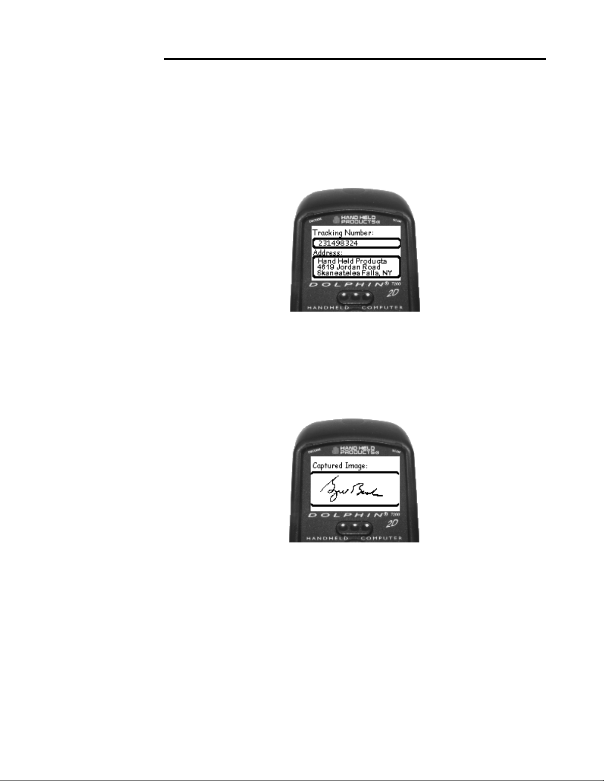
CHAPTER 6 DOLPHIN 7200 2D HANDHELD COMPUTER
Press and hold the ON/SCAN button and aim at the barcode. When the engine
successfully decodes, you will hear a short beep. The image engine will then take an
image of the signature. When the signature is captured, the terminal will beep and the
screen shown below will appear on the screen.
The data shown is information contained in the barcode. Press the <ENTER> key
and the signature captured screen will be displayed as shown below:
Press <ENTER> to return to the “Scan the Test Target” screen. Press F4 to exit the
demo and return to the demo main menu.
79
Page 80

Chapter 7 Using the Dolphin®
7200 HomeBase
Summarizes the features of the Dolphin 7200 HomeBase and explains how
to use it.
80
Page 81

CHAPTER 7 USING THE DOLPHIN 7200 HOMEBASE
Hub of the System
As the hub of your Dolphin system, the Dolphin 7200 HomeBase performs three
important functions – battery management, communications and storage.
Battery Management
The Dolphin 7200 HomeBase uses a charging method that senses when the battery
pack is fully charged and then drops to a trickle charge to keep the battery pack at full
capacity. The battery pack does not need to be discharged before recharging because
this method protects the battery from damage caused by overcharging.
IrDA Optical Communications
The IR communications port on the HomeBase connects with the IrDA port on the
Dolphin. Reliable data communications at speeds of up to 115 baud can be
transmitted by the HomeBase. With no pins or contacts to break, IrDA will work
reliably for years.
The Dolphin 7200 HomeBase can be networked together for mass programming and
charging. Units are individually addressable, allowing each HomeBase to be
automatically loaded with the right information and files for its user.
Convenient Storage
The Dolphin 7200 HomeBase is a safe and convenient storage receptacle for the
Dolphin terminal. The HomeBase also holds a spare charged battery pack.
81
Page 82

NOTE
The Charging Main
Batt LED does not
indicate the battery
status of the Dolphin
terminal.
CHAPTER 7 USING THE DOLPHIN 7200 HOMEBASE
Dolphin 7200 HomeBase Parts and Functions
Dolphin Terminal
Main Serial
Charging Main
Batt LED
Multi Serial
Port
COMM LED Charging Aux
Figure 8 HomeBase Front Panel
Front Panel
The Dolphin’s front panel has one slot:
Batt LED
Port
Dolphin Terminal Well You put the Dolphin in this well to communicate with a host
device and to charge the Dolphin’s batteries.
LEDs There are three LEDs that you can use to monitor the status of battery charging
and communications status:
1. Charging Main Batt LED Turns solid green when the Dolphin Terminal is
properly seated into the Dolphin HomeBase.
2. COMM LED Indicates the status of data transfer between the Host Device and the
Dolphin Terminal as described below:
Comm LED Description
Red LED Data is being sent from the Host Device
to the Dolphin HomeBase.
Green LED Data is being sent from the Dolphin
HomeBase to the Host Device.
Orange LED Data is being sent at high data rates.
Figure 9 Data Transfer States
Charging Aux Batt LED Indicates the status of the auxiliary battery pack in the
3.
Dolphin HomeBase as described in the table below:
82
Page 83

CHAPTER 7 USING THE DOLPHIN 7200 HOMEBASE
Charging Aux Batt LED Description
OFF Battery pack not properly inserted into
the auxiliary battery well, or the
HomeBase has no power
Red Battery discharging
Blinking red LED Charge cycle initializing
Blinking orange LED Battery charging at the maximum rate
Solid green LED Trickle charging; battery pack is ready for
use
Figure 10 Battery Charging States
NOTE
The configuration
switches are checked at
power up. Changes in
the switch settings will
not be recognized until
power is turned off and
then back on.
Back Panel
Aux Battery Well
Service Aux
Batt Switch
Power Supply
Connector
Figure 11 Back Panel of HomeBase
Configuration
Switches
There is an auxiliary battery well, two configuration switches, a discharge button, and a
power supply connector:
Auxiliary battery well Insert a battery into the well to charge a second battery and you
will always have a spare. The auxiliary battery well can also service your battery pack.
83
Page 84

CHAPTER 7 USING THE DOLPHIN 7200 HOMEBASE
M
Configuration switches Use these switches to select the network and communications
modes for your Dolphin. See Chapter 8 for more on the configuration switch settings.
Service Aux Batt switch Press and hold this button for four seconds to service the
battery in the auxiliary battery well. For maximum battery life, the battery should be
serviced, or calibrated once a month. The Charging AUX BATT LED is red while the
battery is discharging and changes to blinking red when the charging cycle begins. The
battery is ready to use when the light turns green.
Power supply connector Use this connector to attach a power supply to the
HomeBase. The power supply provides 12V DC input for communications and
battery charging.
Side Panels
There is a main communications port on one side and a multi-HomeBase-port on the
other side:
Main Communications Port Use a standard serial cable
to connect this port to a host RS-232 device if the
Dolphin HomeBase is the first unit of HomeBase
network. Otherwise, the main communications port
connects to another Dolphin HomeBase MultiHomeBase Port to form a daisy-chained network. See
pinout definitions in the section on Setting Up the Dolphin
HomeBase later in this
chapter.
Figure 12 HomeBase Side Panel
ain Communications Port
Multi-HomeBase Port
Use this port to form a Dolphin
HomeBase Network. This port mates with the next
HomeBase’s main communications port to form an
addressable network. Note: The Multi-HomeBase Port
cannot be used for communications to
standard serial devices.
Figure 13 HomeBase Side Panel MultiHomeBase Port
84
Page 85

CHAPTER 7 USING THE DOLPHIN 7200 HOMEBASE
Charging Batteries In The Dolphin 7200 HomeBase
CAUTION: Use only the 3.6V battery packs provided by Hand Held Products.
The use of any other battery pack in the Dolphin Terminal will void your
warranty and may result in damage to the Dolphin Terminal or battery.
NOTE
For maximum battery life,
Hand Held Products
recommends that you deep-
cycle (service) the battery
twice before initial use
and then, once a month
thereafter.
With the Dolphin HomeBase, you can charge a Dolphin terminal and a spare NiMH
battery pack simultaneously. The HomeBase charges the terminal and the spare battery
pack independently.
When you insert a battery into the Dolphin HomeBase, it charges the battery at the
highest rate possible. The HomeBase uses a charging method that senses when the
battery pack is fully charged and then drops to a trickle charge to keep the battery pack
at full capacity. You do not need to discharge the battery pack before recharging
because this method protects the battery from damage caused by overcharging. A
dead battery will charge to full capacity in approximately three hours.
The Dolphin Terminal can be stored indefinitely in the HomeBase without damage to
the terminal, battery packs, or the HomeBase. Keep the HomeBase plugged in so that
the Dolphin Terminal’s battery pack stays fully charged.
Charging A Dolphin Terminal
1. Insert a battery pack into the Dolphin Terminal.
2. Place the terminal, laser engine window up and the LCD visible, in the Dolphin
Terminal Well of the Dolphin HomeBase.
3. Let it glide down into the well until it stops.
4. Once the Dolphin Terminal is properly seated, the Charging Main Batt LED on
the HomeBase will be solid GREEN.
85
Page 86

CHAPTER 7 USING THE DOLPHIN 7200 HOMEBASE
A
Laser Engine
Window
uxiliary Battery
Well
Charging MAIN
BATT LED
Figure 14 Inserting the Dolphin terminal into the HomeBase
Charging an Additional NiMH Battery Pack
1. Insert an NiMH battery pack with the battery contacts pointing upward into the
Dolphin HomeBase auxiliary battery well.
Charging AUX
BATT LED
Figure 15 Rear View Dolphin HomeBase
Once the battery is inserted into the Dolphin HomeBase you can use the
CHARGING AUXBATT LED to monitor the charging progress. See Figure 10 for a
summary of each charging state.
Deep-cycling the Battery
For maximum battery life, Hand Held Products recommends that you deep- cycle
(service) the battery twice before initial use and then, once a month thereafter. To
deep-cycle, insert the battery into the HomeBase auxiliary battery well. Then, push and
hold the Service Aux Batt button for at least 4 seconds. The deep-cycling process
takes approximately 6.5 hours.
86
Page 87

CHAPTER 7 USING THE DOLPHIN 7200 HOMEBASE
The CHARGING AUXBATT LED is red while the battery is discharging and
changes to blinking red when the charging cycle begins and orange when charging at
the maximum rate. The battery is ready to use when the light turns green. See Figure
10 for more on the LED status.
Setting Up For Communications
The Dolphin Terminal and Dolphin HomeBase support RS-232 communications
through the RS-232 Main Communications Port located on the side of the Dolphin
7200 HomeBase. The HomeBase translates the RS-232 signals from the host
computer into infrared signals to communicate with the Dolphin Terminal.
The HomeBase RS-232 interface allows the Dolphin Terminal to communicate to a
personal computer, modem, or any standard RS-232 device using a standard serial
cable and communications software.
Follow these steps to set up the Dolphin HomeBase and Dolphin Terminal for
communications:
1. Set-up the Dolphin HomeBase.
2. Set-up the Dolphin Terminal.
3. Follow the data transfer sequence as described by your application.
Setting up the Dolphin HomeBase
Set the Dolphin HomeBase on any dry, stable surface such as a desktop. Before
mounting the Dolphin HomeBase, check to ensure that all AC wall transformers have
a nearby electrical outlet. Be sure to provide enough workspace with good lighting for
the user to view and operate the Dolphin Terminal while it is in the HomeBase.
Setting up the HomeBase involves three steps:
1. Connecting the cables
2. Setting the configuration switches
3. Setting the baud rate
Connecting the Cables
Connect the HomeBase to the host computer or other device by plugging an RS-232
serial cable into the RS-232 Communications Port on the rear of the HomeBase. The
87
Page 88

CHAPTER 7 USING THE DOLPHIN 7200 HOMEBASE
wiring of your cable depends on whether the other device is set up as a DCE (Data
Communications Equipment) or DTE (Data Terminal Equipment) device.
The HomeBase RS-232 Port is configured as a DCE device. To communicate with a
DTE device such as a computer, use a standard (or straight-through) RS-232 cable.
To communicate with a DCE device, use either a null modem adapter in line with a
standard RS-232 cable, or a null-modem serial cable.
You can make your own cables by following the pin configuration in the chart below.
To do so, you must determine if your host RS-232 device is 9-pin or 25-pin, and
whether it is configured as a DCE or DTE device.
HomeBase
/Host Port
(DCE)
2 (RD) 2 3 2
3 (TD) 3 2 3
5 (SG) 5 7 7
4 (DTR) 4 20 6
6 (DSR) 6 6 20
7 (RTS) 7 4 5
8 (CTS) 8 5 4
IBM AT DB9
(DTE)
Figure 16 Pin Configuration
IBM XT DB25
(DTE)
Modem DB25
(DCE)
With the Dolphin 7200 HomeBase, use the appropriate cable to connect each device
to the Main Comm Port for a single Dolphin HomeBase or to the Multi-HomeBase
Port if you are creating a Dolphin HomeBase network.
Connect the power supply to the Dolphin HomeBase. Plug the AC transformer into
the Dolphin HomeBase 12 Volt DC power supply connector. The AC wall
transformer provided can power only one Dolphin HomeBase.
Hand Held Products recommends that you leave the Dolphin HomeBase connected
to its power source at all times, so that it is always ready to use.
Setting the Configuration Switches
Use these switches to select the network and communications modes for your
Dolphin HomeBase. If you are configuring the HomeBase for a single Dolphin
Terminal, the switch must be in the ‘Single’ position for proper basic operation. The
switch must be set to ‘Multi’ for proper network operation if you are creating a
HomeBase network. The configuration switch must be in the program position to
change the baud rate.
88
Page 89

CHAPTER 7 USING THE DOLPHIN 7200 HOMEBASE
Setting the Baud Rate
You may use the HomeBase Configuration utility program to select the baud rate. The
program can also be used to change the host system’s COM port and will run a
diagnostic check for optimal communications. After changing the baud rate, you must
power the HomeBase off and then on again. The program is one of the utility
programs that come with the Dolphin OS and Development System. For more on
HomeBase Configuration, see the chapter 9.
Modes of Operation
Through the Command Mode, the host application software provides command
instructions for configuring a single Dolphin HomeBase or a network of HomeBases
for communications. Once configured, the HomeBase(s) is in Transparent Mode and
ready for communications.
Command Mode
You can configure a single Dolphin HomeBase or a whole network and select units
for communications via the host application by entering the Command Mode. Data
transmission is not possible while the Dolphin HomeBase network is in this mode.
Go into Command Mode by entering an escape sequence that informs the HomeBase
network that it will be receiving commands from the host device or application. The
escape string is:
<ESC>HHP [>100ms<1s] Next Command
where <ESC> is an ASCII 27 character. The escape string should be followed by a
>100ms<1second period of line silence. When sending commands, the escape string
must precede the command string. The HomeBase automatically exits Command
Mode after receiving each command.
Programming commands used for configuring single Dolphin HomeBases include
Version Number and Baud Rate Selection. You configure HomeBase networks using
the Baud Rate Selection, Address Assignment and Device Selection programming
commands. See the sections on Configuring A Single Dolphin HomeBase and Creating a
HomeBase Network for details.
Transparent Mode
When the Dolphin HomeBase is selected by the host application and ready for
communications, it is in Transparent Mode. In this mode, the HomeBase facilitates
point-to-point communication between the host device and the Dolphin Terminal.
Data sent through the RS-232 link is passed directly to and from the Dolphin Terminal
via the Infrared Link between the terminal and the HomeBase.
89
Page 90

NOTE
The configuration
switches are checked at
power up. Changes in the
switch settings will not be
recognized until power is
turned off and
then back on.
NOTE
The baud rate is stored
in Non-Volatile Memory
and is retained even if
the power is removed
from the network.
CHAPTER 7 USING THE DOLPHIN 7200 HOMEBASE
Configuring a Single Dolphin 7200 HomeBase
To prepare a single Dolphin HomeBase for communications, you must enter the
Command Mode to configure the version number and select the baud rate.
Version Number
To retrieve the version number for the Dolphin HomeBase:
1. Enter or send the escape and command strings:
<ESC>HHP >100ms< 1s V
This command will return the version number but is not needed for communications.
Baud Rate Selection
The Dolphin HomeBase baud rate is set to 57600 at the factory. Use the configuration
switches on the HomeBase’s back panel to select the network and communications
modes for your Dolphin. The following table outlines the configuration switch
settings:
Switch Setting Function
1 SINGLE (UP) Single HomeBase only
2 FIXED BPS
Baud rate fixed at 9600
(DOWN)
2 PROGRAM (UP) Baud rate can be programmed
Figure 17 Configuration Switch Settings on HomeBase for Single HomeBase
To ensure communications, leave Switch 2 in the ‘FIXED BPS’ position and configure
your communications software for 9600 baud. When Switch 2 is in the ‘PROGRAM’
position, the baud rate can be changed using the following procedure or you may use
the HomeBase Configuration Utility program.
1. Enter or send the escape and command strings:
<ESC>HHP >100ms< 1s B
n
where n is the ASCII number corresponding to the baud rate shown in
the table below. For example, the string <ESC>HHPB6 (which consists
of the escape string and the command B6) would set the baud rate for the
network to 19200. No response will be transmitted back to the host after
executing this function.
90
Page 91

CHAPTER 7 USING THE DOLPHIN 7200 HOMEBASE
ASCII Value
of “n”
Selected
Baud Rate
ASCII Value
of “n”
Selected Baud
Rate
0 38400 6 19200
1 38400 7 38400
2 1200 8 57600
3 2400 9 115200
5 9600
Figure 18 Baud Rate per Value of n
Creating a Dolphin 7200 HomeBase Network
This information applies only to the Dolphin 7200 HomeBase. The Dolphin 7200
Compact HomeBase is not networkable. Each HomeBase must have its own AC
power adapter connected to a standard AC electrical socket. The group can be placed
on a table or desk, or rail-mounted using the mounting holes on the two outside
Dolphin HomeBase units.
How to Daisy Chain the Dolphin HomeBases
To form a HomeBase network, daisy chain the HomeBases together using one of the
following methods:
• Align adjacent units so that the MULTI-HOMEBASE PORT of one unit
will mate with the MAIN COMM PORT of the next unit until all
HomeBases in the network are connected.
OR
• Use a RS-232 cable to connect the Multi-HomeBase Port on one terminal
to the MAIN COMM PORT on the next terminal. Repeat this step to
include each additional terminal in the chain. Connect the last terminal to
the host computer and leave the last MULTI-HOMEBASE PORT open
if it is not needed.
Programming Commands
To configure a Dolphin HomeBase network, these attributes must be programmed:
Address Assignment, Baud Rate Selection and Device Selection.
Address Assignment
Use the Address Assignment command to establish unit IDs for each Dolphin
HomeBase in your network. This must be done before a unit can be selected for
communications. To establish an Address Assignment:
91
Page 92

CHAPTER 7 USING THE DOLPHIN 7200 HOMEBASE
1. Type or send the escape and command strings to set-up the configuration mode
and establish the beginning unit ID number:
NOTE
The configuration
switches are checked at
power up. Changes in the
switch settings will not be
recognized until power is
turned off and
back on.
<ESC>HHP >100 ms< C >100 ms< 1s I
n is the number representing the first unit in the network
For example, the string <ESC>HHPCI0 would instruct the network to set up ID
n
numbers for all the units in the network beginning at zero (0).
2. The first Dolphin HomeBase in the network receiving the command responds to
the host with:
<SYN>
<SYN> indicates that the command was accepted
3. In sequence, each Dolphin HomeBase will determine its own ID number by
adding one to the previous ID number.
4. When ID numbers are established for all HomeBases, the last HomeBase will
return this response to the host:
<ACK>n
<ACK> indicates completion of ID configuration; n represents the ID number
for the last unit in the network.
Programmer’s Note: When sending ID numbers to the Dolphin HomeBase, remember
that numbers typed on the keyboard are ASCII numbers which will be converted to Hex
when sent to the Dolphin HomeBase. For example, typing the command from the
keyboard:
<ESC>HHP >100ms< C >100ms< 1s I1
would instruct the network to set up ID numbers for each Dolphin HomeBase starting
with the ASCII number 1. The first unit in the network would actually receive the
number 31 Hex (since ASCII 1 is equal to 31 Hex) as the starting ID number. Each unit
in the network would sequentially add one to this starting ID number to establish its
own ID. So, for a network of 15 units, the final ID number would be set up as 3F Hex.
When the final unit sends back an <ACK>3F, the host computer (which converts Hex
data back to ASCII) will then display the ID number as “?” instead of 15 as you might
expect.
Baud Rate Selection
The Dolphin HomeBase baud rate is preset to 57600 at the factory. Use the
configuration switches on the back panel of the HomeBase to select the network and
communications modes for your Dolphin. The following table outlines the
configuration switch settings:
92
Page 93

CHAPTER 7 USING THE DOLPHIN 7200 HOMEBASE
Switch Setting Function
2 FIXED BPS
Baud rate fixed at 9600
(DOWN)
2 PROGRAM
Baud rate can be programmed
(UP)
Figure 19 Configuration Switch Settings for a HomeBase Network
When Switch 2 is in the ‘PROGRAM’ position, the baud rate can be changed using
the following procedure or by using the HomeBase Configuration Utility.
Enter or send the escape and command strings:
<ESC>HHP >100ms< 1s Bn
n is the ASCII number corresponding to the baud rate shown in the table below. For
example, the string <ESC>HHPB6 (which consists of the escape string and the
command B6) would set the baud rate for the network to 19200. No response will be
transmitted back to the host after executing this function.
ASCII Value
of “n”
Selected
Baud Rate
ASCII Value
of “n”
Selected Baud
Rate
0 38400 6 19200
1 38400 7 38400
2 1200 8 57600
3 2400 9 115200
5 9600
Figure 20 Baud Rate per Value of n
NOTE
The baud rate is stored in
Non-Volatile Memory and is
retained even if the power is
removed from the network.
Device Selection
Use this command to enable the host device to select a specific Dolphin HomeBase in
the network for communication.
1. Enter or send the escape and command strings:
<ESC>HHP >100ms< 1s S
where n is the unit ID of the Dolphin HomeBase being selected
2. The Dolphin HomeBase with the unit ID corresponding to the ID number in the
n
Device Selection command string will respond with:
<ACK>n
to indicate to the host that it is present. n is the unit ID.
93
Page 94

CHAPTER 7 USING THE DOLPHIN 7200 HOMEBASE
When data transfer begins, the COMM LED on the Dolphin HomeBase will blink red
and green. A unit remains selected until another unit in the network is selected. For
example, the string <ESC>HHPS3 would select the unit with ID number 3 for
communications. That unit would then send back an <ACK>3.
A selected unit in the Dolphin HomeBase network will assert the DSR signal of the
HomeBase when a Dolphin terminal is present. The DSR signal can be used by the
host application to determine if a Dolphin terminal is present and selected.
94
Page 95

CHAPTER 7 USING THE DOLPHIN 7200 HOMEBASE
Communicating with the Dolphin Terminal
To communicate with the Dolphin and any other devices connected to the
HomeBase:
1. Insert the Dolphin into the terminal well of the HomeBase. If the Dolphin is in
sleep mode, it will awaken into active state.
2. The CHARGING MAINBATT LED on the HomeBase will turn on. If the
Dolphin does not turn on, or the LED does not light up, make sure that it is
properly seated in the terminal well and that the power supply is properly
connected to the HomeBase and plugged into a functioning AC outlet.
3. Start your application on the Dolphin terminal or the host computer. Data can
then begin transmitting between the terminal and the devices connected to the
Dolphin HomeBase.
When data transfer begins, the COMM LED on the Dolphin HomeBase will blink red
and green. If the HomeBase will not communicate with the Dolphin, check the port
connections to ensure that the HomeBase is correctly configured. See Chapter 10,
Troubleshooting, for more information.
95
Page 96

Chapter 8 Using the Dolphin®
7200 Compact HomeBase
Summarizes the features of the Dolphin 7200 Compact HomeBase and
explains how to use it.
96
Page 97

CHAPTER 8 USING THE DOLPHIN 7200 COMPACT HOMEBASE
Hub of the System
As the hub of your Dolphin system, the Dolphin 7200 Compact HomeBase performs
three important functions – battery management, communications and storage.
Battery Management
The Dolphin 7200 Compact HomeBase uses a charging method that senses when the
battery pack is fully charged and then drops to a trickle charge to keep the battery pack
at full capacity. The battery pack does not need to be discharged before recharging
because this method protects the battery from damage caused by overcharging.
The Dolphin 7200 Compact HomeBase provides power to the Dolphin terminal to
enable the terminal to charge its battery.
IrDA Optical Communications
The IR communications port on the Compact HomeBase connects with the IrDA
port on the Dolphin. Reliable data communications at speeds of up to 115 baud can
be transmitted by the HomeBase. With no pins or contacts to break, IrDA will work
reliably for years.
The Dolphin 7200 Compact HomeBase is not networkable.
Convenient Storage
The Dolphin 7200 Compact HomeBase is a safe and convenient storage receptacle for
the Dolphin terminal.
97
Page 98

e
DOCK
LED
CHAPTER 8 USING THE DOLPHIN 7200 COMPACT HOMEBASE
Dolphin 7200 Compact HomeBase Parts and
Functions
Front Panel
Figure 16 Front View of HomeBas
The Compact HomeBase’s front panel has one slot:
COMM
LED
Dolphin Terminal Well You put the Dolphin in this well to communicate with a host
device and to charge the Dolphin’s batteries.
LEDs There are two LEDs on the front panel of the HomeBase
1. DOCK LED Turns solid green when the Dolphin Terminal is properly seated into
the Dolphin HomeBase.
2. COMM LED Indicates the status of data transfer between the Host Device and the
Dolphin Terminal as described below:
Comm LED Description
Red LED Data is being sent from the Host Device
to the Dolphin HomeBase.
Green LED Data is being sent from the Dolphin
HomeBase to the Host Device.
Orange LED Data is being sent at high data rates.
98
Page 99

CHAPTER 8 USING THE DOLPHIN 7200 COMPACT HOMEBASE
Back Panel
Power
Supply
Connector
Figure 17 HomeBase Back Panel
RS-232
Connector
There is a power supply connector and an RS232 connector:
Power supply connector Use this connector to attach a power supply to the
HomeBase. The power supply provides 12V DC input for communications and
battery charging.
NOTE
The HomeBase
Configuration program
be used to select the
cannot
baud rate on the Compact
HomeBase.
RS-232 Communications Port Use a standard serial cable to connect this port to a host
RS-232 device.
Bottom Panel
A Baud Rate DIP switch is located on the bottom of the HomeBase. The threeposition DIP switch is used to select the communication baud rate. Switch position
and the corresponding baud rates are shown in the chart below.
Baud Rate
Switch
Figure 18 HomeBase Bottom Panel
99
Page 100

CHAPTER 8 USING THE DOLPHIN 7200 COMPACT HOMEBASE
Baud Rate Switch 1 Switch 2 Switch 3
115200 0 0 0
57600 1 0 0
19200 0 1 0
9600 1 1 0
38400 0 0 1
4800 1 0 1
2400 0 1 1
Note: The HomeBase Configuration program cannot
Compact HomeBase.
be used to select the baud rate on the
Powering the Dolphin Terminal
When seated in the HomeBase, the Dolphin terminal receives the power it needs to
charge the battery and to run its internal circuitry.
The Dolphin terminal can be stored indefinitely in the HomeBase without damage to
the terminal or the HomeBase. Keep the HomeBase plugged in so that the Dolphin
terminal’s battery pack stays fully charged.
Charging A Dolphin Terminal
The HomeBase supplies charging power to the Dolphin terminal so that the terminal
can monitor the charging of its battery pack. This charging method protects the battery
from being damaged by overcharging. Therefore, the Dolphin terminal may be stored
indefinitely in the HomeBase without damage to the terminal, the battery pack, or the
HomeBase.
To charge a Dolphin terminal, follow these steps:
1. Insert a battery pack into the Dolphin terminal.
2. Place the terminal, laser engine window up and the LCD visible, in the Dolphin
Terminal Well of the Dolphin HomeBase.
3. Let it glide down into the well until it stops.
100
 Loading...