

Page 1
4800p
™
User’s Guide
4800p 2D Imager
Page 2

Disclaimer
Hand Held Products, Inc. (“Hand Held Products”) reserves the right to make
changes in specifications and other information contained in this document
without prior notice, and the reader should in all cases consult Hand Held
Products to determine whether any such changes have been made. The
information in this publication does not represent a commitment on the part of
Hand Held Products.
Hand Held Products shall not be liable for technical or editorial errors or
omissions contained herein; nor for incidental or consequential damages
resulting from the furnishing, performance, or use of this material.
This document contains proprietary information that is protected by copyright. All
rights are reserved. No part of this document may be photocopied, reproduced,
or translated into another language without the prior written consent of Hand
Held Products.
2007 Hand Held Products, Inc. All rights reserved.
Web Address:
Microsoft
Corporation in the United States and/or other countries.
Macintosh
other countries.
Other product names or marks mentioned in this document may be trademarks
or registered trademarks of other companies and are the property of their
respective owners.
www.handheld.com
®
Windows® is either a registered trademark or trademarks of Microsoft
®
is a trademark of Apple Computer, Inc., registered in the U.S. and
FCC Compliance Statement
This device complies with part 15 of the FCC Rules. Operation is subject to the
following two conditions: (1) this device may not cause harmful interference, and
(2) this device must accept any interference received, including interference that
may cause undesired operation.
FCC Class B Compliance Statement
This equipment has been tested and found to comply with the limits for a Class
B digital device pursuant to part 15 of the FCC Rules. These limits are designed
to provide reasonable protection against harmful interference in a residential
installation. This equipment generates, uses, and can radiate radio frequency
energy and, if not installed and used in accordance with the instructions, may
cause harmful interference to radio communications. However, there is no
guarantee that interference will not occur in a particular installation. If this
equipment does cause harmful interference to radio or television reception,
which can be determined by turning the equipment off and on, the user is
encouraged to try to correct the interference by one or more of the following
measures:
• Reorient or relocate the receiving antenna.
Page 3

• Increase the separation between the equipment and receiver.
• Connect the equipment into an outlet on a circuit different from that to which
the receiver is connected.
• Consult the dealer or an experienced radio or television technician for help.
Caution: Any changes or modifications made to this equipment not
expressly approved by Hand Held Products, Inc. may void the
FCC authorization to operate this equipment.
Note: To maintain compliance with FCC Rules and Regulations, cables
connected to this device must be Hand Held Products approved shielded
cables, in which the cable shield wire(s) have been grounded (tied) to the
connector shell. Installation of the included ferrite is required to meet
emission requirements.
Canadian Notice
This equipment does not exceed the Class B limits for radio noise emissions as
described in the Radio Interference Regulations of the Canadian Department of
Communications.
Le present appareil numerique n’emet pas de bruits radioelectriques depassant
les limites applicables aux appareils numeriques de la classe B prescrites dans
le Reglement sur le brouillage radioelectrique edicte par le ministere des
Communications du Canada.
Note: To maintain compliance with FCC Rules and Regulations, cables
connected to this device must be shielded cables, in which the cable
shield wire(s) have been grounded (tied) to the connector shell.
Installation of the included ferrite is required to meet emission
requirements.
CE Mark
The CE mark on the product indicates that the system has been
tested to and conforms with the provisions noted within the 2004/108/
EC Electromagnetic Compatibility Directive and the 2006/95/EC Low
Voltage Directive.
Complies with:
EN55022:2006 (for ITE emissions)
EN55024:1998 (for ITE immunity)
EN61000-3-2:2000
EN61000-3-3:1995
For further information please contact:
Hand Held Products
Nijverheidsweg 9-13
5627 BT Eindhoven
The Netherlands
Page 4

Hand Held Products, Inc. shall not be liable for use of our product with equipment
(i.e., power supplies, personal computers, etc.) that is not CE marked and does
not comply with the Low Voltage Directive.
Note: To maintain compliance with FCC Rules and Regulations, cables
connected to this device must be shielded cables, in which the cable
shield wire(s) have been grounded (tied) to the connector shell.
Installation of the included ferrite is required to meet emission
requirements.
UL and cUL Statement
UL and cUL listed: UL60950-1 and CSA C22.2 No.60950-1.
LED Safety Statement
This device has been tested in accordance with EN60825-1:1993+A1+A2 LED
safety, and has been certified as a Class 1 LED device.
GS Mark
This product has been issued a GS certificate.
Patents
Please refer to the product packaging for a list of patents.
Waste Electrical and Electronic Equipment Information
For European Community Users
Note: Hand Held Products complies with Directive 2002/96/EC OF THE
EUROPEAN PARLIAMENT AND OF THE COUNCIL of 27 January 2003
on waste electrical and electronic equipment (WEEE).
This product has required the extraction and use of natural resources for its
production. It may contain hazardous substances that could impact health and
the environment, if not properly disposed.
Page 5

In order to avoid the dissemination of those substances in our environment and
to diminish the pressure on the natural resources, we encourage you to use the
appropriate take-back systems for product disposal. Those systems will reuse or
recycle most of the materials of the product you are disposing in a sound way.
The crossed out wheeled bin symbol informs you that the product should
not be disposed of along with municipal waste and invites you to use the
appropriate separate take-back systems for product disposal.
If you need more information on the collection, reuse, and recycling systems,
please contact your local or regional waste administration.
You may also contact your supplier for more information on the environmental
performances of this product.
Page 6

Page 7

Table of Contents
Chapter 1 - Getting Started
About This Manual ............................................................... 1-1
Unpacking the Imager........................................................... 1-1
Imager Models ...................................................................... 1-2
Imager Identification ............................................................ 1-2
Connecting the Imager with USB ........................................ 1-3
Programming the Interface - Plug and Play.......................... 1-4
USB PC or Macintosh® Keyboard ................................. 1-4
USB HID........................................................................ 1-4
USB COM Port Emulation............................................. 1-5
Reading Techniques.............................................................. 1-5
4800p Stand .......................................................................... 1-6
Chapter 2 - Terminal Interfaces
Terminal ID .......................................................................... 2-1
Supported Terminals............................................................. 2-2
Keyboard Country ................................................................ 2-3
Keyboard Style ..................................................................... 2-5
Keyboard Modifiers ............................................................. 2-7
Chapter 3 - Output
Good Read Indicators ........................................................... 3-1
Beeper – Good Read ...................................................... 3-1
Beeper Volume – Good Read ........................................ 3-1
Beeper Pitch – Good Read ............................................. 3-2
Beeper Duration – Good Read ....................................... 3-2
Number of Beeps – Good Read ..................................... 3-2
Good Read Delay.................................................................. 3-3
User-Specified Good Read Delay......................................... 3-3
Reread Delay ........................................................................ 3-4
User-Specified Reread Delay ............................................... 3-4
LED Power Level ................................................................. 3-5
Centering............................................................................... 3-5
i
Page 8

Decode Search Mode............................................................ 3-7
Output Sequence Overview .................................................. 3-7
Output Sequence Editor ............................................... 3-10
Require Output Sequence............................................. 3-10
Print Weight........................................................................ 3-11
Video Reverse..................................................................... 3-11
Working Orientation........................................................... 3-12
Chapter 4 - Data Editing
Prefix/Suffix Overview......................................................... 4-1
To Add a Prefix or Suffix: ............................................. 4-2
To Clear One or All Prefixes or Suffixes:...................... 4-3
To Add a Carriage Return Suffix to all Symbologies .... 4-3
Prefix Selections............................................................. 4-4
Suffix Selections ............................................................ 4-4
Function Code Transmit................................................. 4-4
Intercharacter, Interfunction, and Intermessage Delays ....... 4-5
Intercharacter Delay ....................................................... 4-5
User Specified Intercharacter Delay .............................. 4-6
Interfunction Delay ........................................................ 4-6
Intermessage Delay ........................................................ 4-7
Chapter 5 - Data Formatting
Data Format Editor Introduction .......................................... 5-1
To Add a Data Format.................................................... 5-1
Other Programming Selections ...................................... 5-2
Data Format Editor Commands ..................................... 5-2
Data Format Editor......................................................... 5-5
Data Formatter ............................................................... 5-5
Alternate Data Formats .................................................. 5-6
ii
Page 9

Chapter 6 - Symbologies
Message Length Description................................................. 6-2
Codabar Start/Stop Characters....................................... 6-3
Codabar Check Character............................................... 6-3
Codabar Concatenation .................................................. 6-4
Codabar Message Length ............................................... 6-5
Code 39 Start/Stop Characters ....................................... 6-6
Code 39 Check Character............................................... 6-6
Code 39 Message Length ............................................... 6-7
Code 39 Append............................................................. 6-8
Code 32 Pharmaceutical (PARAF) ................................ 6-8
Full ASCII ...................................................................... 6-9
Code 39 Code Page ...................................................... 6-10
Check Digit................................................................... 6-10
Interleaved 2 of 5 Message Length .............................. 6-11
Code 93 Message Length ............................................. 6-12
Code 93 Code Page ...................................................... 6-12
Straight 2 of 5 Industrial Message Length ................... 6-13
Straight 2 of 5 IATA Message Length ......................... 6-14
Matrix 2 of 5 Message Length ..................................... 6-15
Check Digits Required ................................................. 6-16
Code 11 Message Length ............................................. 6-16
ISBT 128 Concatenation .............................................. 6-17
Code 128 Message Length ........................................... 6-18
Code 128 Code Page .................................................... 6-18
Telepen Output ............................................................. 6-19
Telepen Message Length.............................................. 6-19
UPC-A Check Digit...................................................... 6-20
UPC-A Number System ............................................... 6-20
UPC-A Addenda........................................................... 6-21
UPC-A Addenda Required........................................... 6-21
UPC-A Addenda Separator .......................................... 6-21
UPC-E0 ........................................................................ 6-22
UPC-E0 Expand ........................................................... 6-22
UPC-E0 Addenda Required ......................................... 6-23
UPC-E0 Addenda Separator......................................... 6-23
iii
Page 10

UPC-E0 Check Digit.................................................... 6-23
UPC-E0 Number System ............................................. 6-24
UPC-E0 Addenda......................................................... 6-24
EAN/JAN-13 Check Digit ........................................... 6-25
EAN/JAN-13 Addenda ................................................ 6-26
EAN/JAN-13 Addenda Required................................. 6-26
EAN/JAN-13 Addenda Separator ................................ 6-26
ISBN Translate............................................................. 6-27
EAN/JAN-8 Check Digit ............................................. 6-27
EAN/JAN-8 Addenda .................................................. 6-28
EAN/JAN-8 Addenda Required................................... 6-28
EAN/JAN-8 Addenda Separator.................................. 6-28
MSI Check Character................................................... 6-29
MSI Message Length ................................................... 6-30
Plessey Message Length .............................................. 6-30
RSS Expanded Message Length .................................. 6-32
PosiCode Message Length ........................................... 6-33
Codablock F Message Length...................................... 6-34
Code 16K Message Length .......................................... 6-35
Code 49 Message Length ............................................. 6-36
PDF417 Message Length ............................................. 6-37
MicroPDF417 Message Length ................................... 6-38
UPC/EAN Version ....................................................... 6-39
EAN•UCC Composite Code Message Length............. 6-39
4-CB (4-State Customer Bar Code) ............................. 6-41
ID-tag (UPU 4-State) ................................................... 6-41
Postnet.......................................................................... 6-41
Planet Code .................................................................. 6-42
British Post................................................................... 6-43
Canadian Post............................................................... 6-43
Kix (Netherlands) Post................................................. 6-43
Australian Post ............................................................. 6-44
Australian Post Interpretation ...................................... 6-44
Japanese Post................................................................ 6-44
China Post Message Length ......................................... 6-45
Korea Post Message Length......................................... 6-46
QR Code Message Length ........................................... 6-47
iv
Page 11

Data Matrix Message Length ....................................... 6-48
MaxiCode Message Length..........................................6-49
Aztec Code Message Length........................................ 6-50
Aztec Runes.................................................................. 6-50
Chapter 7 - Imaging Commands
Image Snap - IMGSNP ......................................................... 7-1
IMGSNP Modifiers ........................................................ 7-1
Image Ship - IMGSHP.......................................................... 7-2
IMGSHP Modifiers ........................................................ 7-3
Image Size Compatibility............................................... 7-6
Intelligent Signature Capture - IMGBOX............................. 7-7
IMGBOX Modifiers ....................................................... 7-7
Chapter 8 - OCR Programming
OCR ...................................................................................... 8-1
OCR Templates..................................................................... 8-3
Creating an OCR Template ............................................ 8-3
Stringing Together Multiple Formats
(Creating “Or” Statements) ............................................ 8-6
OCR User-Defined Variables ............................................... 8-6
Reading Multi-Row OCR............................................... 8-7
OCR Check Character........................................................... 8-8
OCR Modulo 10 Check Character ................................. 8-8
OCR Modulo 36 Check Character ................................. 8-9
OCR User-Defined Check Character.................................... 8-9
Weighting Options ....................................................... 8-10
OCR ISBN Application Example ....................................... 8-12
OCR Template Codes ......................................................... 8-13
Chapter 9 - Interface Keys
Keyboard Function Relationships......................................... 9-1
Supported Interface Keys...................................................... 9-3
v
Page 12

Chapter 10 - Utilities
To Add a Test Code I.D. Prefix to All Symbologies.......... 10-1
Show Decoder Revision ..................................................... 10-1
Show Engine Revision........................................................ 10-1
Show Scan Driver Revision................................................ 10-2
Show Software Revision..................................................... 10-2
Show Data Format .............................................................. 10-2
Resetting the Standard Product Defaults ............................ 10-2
Test Menu ........................................................................... 10-3
2D PQA (Print Quality Assessment) .................................. 10-3
2D PQA Reporting....................................................... 10-3
Visual Xpress™ Introduction .............................................. 10-4
Installing Visual Xpress from the Web........................ 10-5
Chapter 11 - Serial Programming Commands
Conventions ........................................................................ 11-1
Menu Command Syntax ..................................................... 11-1
Query Commands......................................................... 11-2
Concatenation of Multiple Commands ........................ 11-2
Responses..................................................................... 11-2
Examples of Query Commands ................................... 11-3
Resetting the Standard Product Defaults ............................ 11-4
Menu Commands................................................................ 11-5
Chapter 12 - Product Specifications
4800p Specifications........................................................... 12-1
Connector Pinouts ........................................................ 12-2
Chapter 13 - Maintenance
Repairs ................................................................................ 13-1
Maintenance........................................................................ 13-1
Cleaning the Device ..................................................... 13-1
Inspecting Cords and Connectors................................. 13-1
Replacing the Interface Cable ...................................... 13-2
vi
Page 13

Troubleshooting .................................................................. 13-2
Chapter 14 - Customer Support
Technical Assistance........................................................... 14-1
Online Technical Assistance ........................................ 14-2
For Further Information................................................ 14-2
Product Service and Repair................................................. 14-2
Online Product Service and Repair Assistance ............ 14-3
Limited Warranty................................................................ 14-3
Appendix A
Symbology Chart ................................................................. A-1
ASCII Conversion Chart (Code Page 1252)........................ A-4
Code Page Mapping of Printed Bar Codes .......................... A-6
vii
Page 14

viii
Page 15

1
Getting Started
About This Manual
This User’s Guide provides installation and programming instructions for the
4000 Series imagers. Product specifications, dimensions, warranty, and
customer support information are also included.
Hand Held Products bar code imagers are factory programmed for the most
common terminal and communications settings. If you need to change these
settings, programming is accomplished by scanning the bar codes in this guide.
An asterisk (*) next to an option indicates the default setting.
Unpacking the Imager
After you open the shipping carton, take the following steps:
• Check for damage during shipment. Report damage immediately to the
carrier who delivered the carton.
• Make sure the items in the carton match your order.
• Save the shipping container for later storage or shipping.
4800p 2D Imager User’s Guide 1 - 1
Page 16
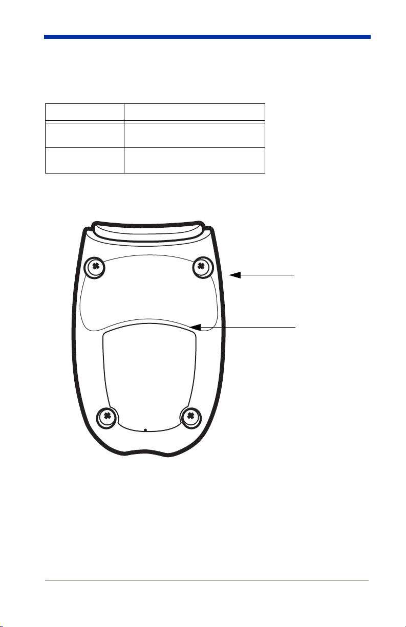
Imager Models
Item Number,
Serial Number
and Revision
Information
location
Compliance
Label location
The chart below lists the interfaces that can be used with your imager.
Models Primary
4800pSF151CE USB keyboard, USB COM port
emulation
4800pSF151C0F00E
USB kit
Imager Identification
1 - 2 4800p 2D Imager User’s Guide
Page 17
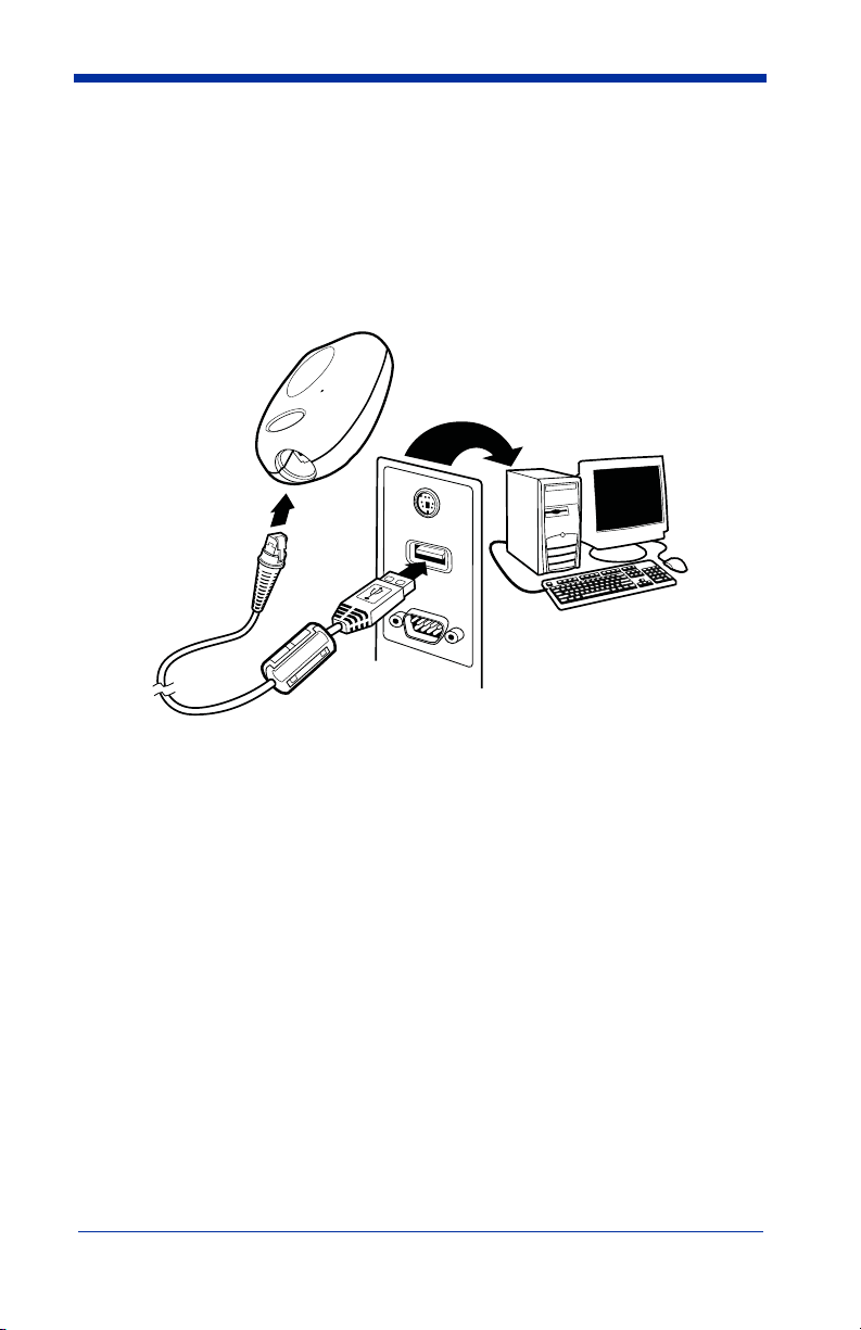
Connecting the Imager with USB
Note: See "Imager Models" on page 1-2 to determine which interfaces apply to
your imager.
An imager can be connected to the USB port of a computer.
1. Connect the appropriate interface cable to the imager first, then to the computer.
2. Program the imager for a USB interface using the Plug and Play bar codes
beginning on
3. The imager beeps.
4. Verify the imager operation by scanning a bar code from the
Symbols
For additional USB programming and technical information, refer to Hand Held
Products “USB Application Note,” available at
page 1-4.
Sample
in the back of this manual.
www.handheld.com.
4800p 2D Imager User’s Guide 1 - 3
Page 18

Programming the Interface - Plug and Play
USB Keyboard (PC)
USB Keyboard (Mac)
USB Japanese Keyboard (PC)
USB HID Bar Code Imager
Plug and Play bar codes provide instant imager set up for commonly used
interfaces.
Note: After you scan one of the codes, power cycle the host terminal to have the
interface in effect.
Note: See
"Imager Models" on page 1-2 to determine which interfaces apply to
your imager.
USB PC or Macintosh® Keyboard
Scan one of the following codes to program the imager for USB PC Keyboard or
USB Macintosh Keyboard. Scanning these codes adds a CR and selects the
terminal ID (USB PC Keyboard - 124, USB Macintosh Keyboard - 125, USB
Japanese Keyboard - 134).
USB HID
Scan the following code to program the imager for USB HID bar code imagers.
Scanning this code changes the terminal ID to 131.
1 - 4 4800p 2D Imager User’s Guide
Page 19

USB COM Port Emulation
USB COM Port Emulation
On
* Off
On
* Off
Scan the following code to program the imager to emulate a regular RS-232based COM port. If you are using a Microsoft® Windows® PC, you will need to
download a driver from the Hand Held Products website (
The driver will use the next available COM port number. Apple® Macintosh
computers recognize the imager as a USB CDC class device and automatically
use a class driver. Scanning the code below changes the terminal ID to 130.
Note: No extra configuration (e.g., baud rate) is necessary.
CTS/RTS Emulation
ACK/NAK Mode
www.handheld.com).
Reading Techniques
The 4800p scans bar codes and also captures images. It can be used with or
without a stand.
4800p 2D Imager User’s Guide 1 - 5
Page 20
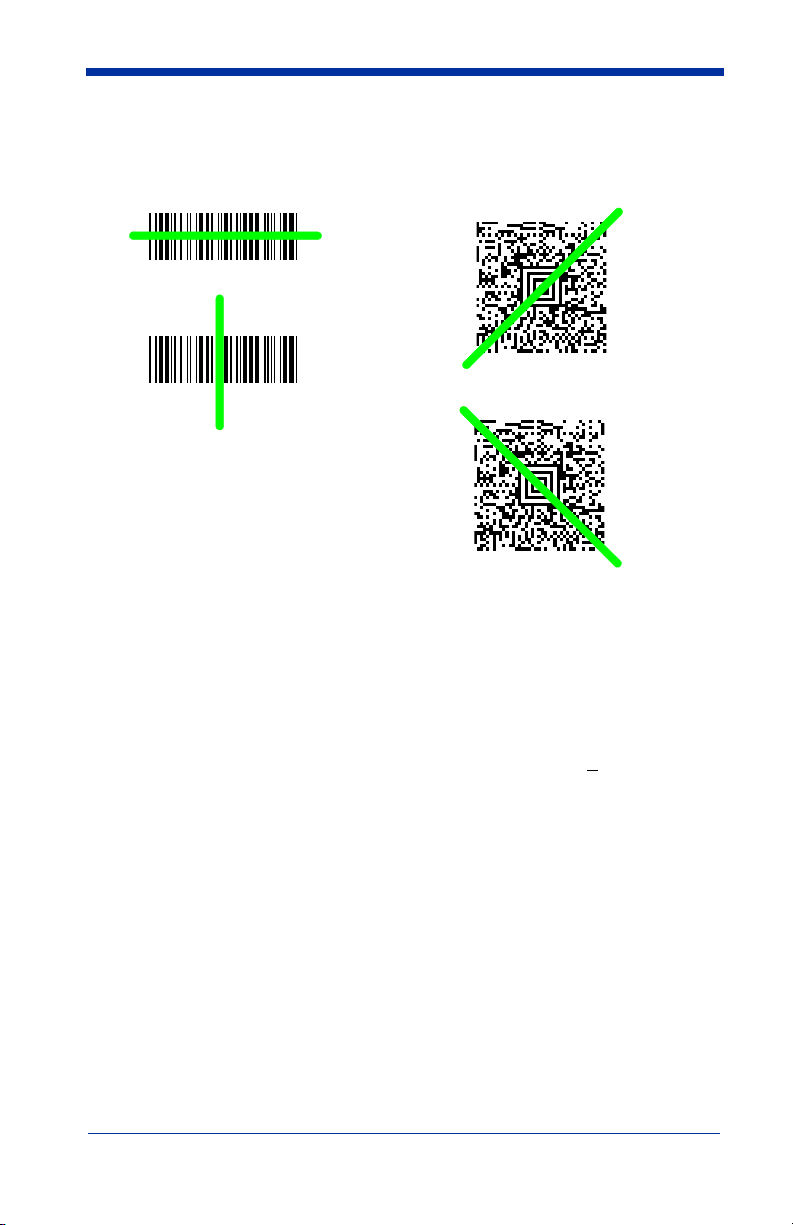
The 4800p’s viewfinder projects a green aiming beam that should be centered
Linear bar code 2D Matrix symbol
over the bar code, but can be positioned in any direction for a good read.
Hold the scanner with the aiming beam centered over the bar code. The 4800p
beeps when it successfully reads a bar code. Do not move the 4800p over
another bar code until it beeps. The optimum distance between the 4800p and
the object being scanned is 2 to 5 inches (5.1 - 12.7 cm). The height from the
4800p to the stand’s tray is the proper distance.
The aiming beam is smaller when the imager is closer to the code and larger
when it is farther from the code. Symbologies with smaller bars or elements (mil
size) should be read closer to the unit. Symbologies with larger bars or elements
(mil size) should be read farther from the unit. If the code being scanned is highly
reflective (e.g., laminated), it may be necessary to tilt the code +
unwanted reflection.
5° to prevent
Stand
4800p
The stand holds the 4800p at a fixed distance for capturing images or reading
bar codes on security/identification cards. The wedge insert supplied with the
stand provides the optimum angle for scanning and capturing images in most
lighting conditions. The card should be placed on the wedge with the bar code
closest to the back of the stand.
1 - 6 4800p 2D Imager User’s Guide
Page 21

2
Terminal ID
Save
Terminal Interfaces
Terminal ID
If your interface is not covered by a Plug and Play bar code from Chapter 1, then
refer to
Supported Terminals on page 2-2, and locate the Terminal ID number for
your PC. Scan the
code(s) from the
program the imager for your terminal ID. Scan
For example, an IBM AT terminal has a Terminal ID of 003. You would scan the
Terminal ID
cover of this manual, then
(before scanning Save), scan the
Terminal ID
the
Note: After scanning one of these codes, you must power cycle your computer.
Terminal ID
Programming Chart inside the back cover of this manual to
bar code, then
bar code, scan the digits, and the
bar code below, then scan the numeric bar
Save
to save your selection.
0, 0, 3
from the Programming Chart inside the back
Save
. If you make an error while scanning the digits
Discard
code on the Programming Chart, scan
Save
code again.
4800p 2D Imager User’s Guide 2 - 1
Page 22

Supported Terminals
Note: See "Imager Models" on page 1-2 to determine which interfaces apply to
your imager.
Ter minal Model(s)
USB PC Keyboard
USB Mac Keyboard
USB HID POS
USB COM Port Emulation
USB Japanese Keyboard
*Default for 4800p model
Terminal
ID
124
125
131
130*
134
2 - 2 4800p 2D Imager User’s Guide
Page 23
Keyboard Country
* United States
Brazil
Czech Republic
Denmark
Finland (Sweden)
France
Germany/Austria
Greece
Hungary
Belgium
Canada (French)
Israel (Hebrew)
Scan the appropriate country code below to program the keyboard for your
country. As a general rule, the following characters are supported, but need
special care for countries other than the United States:
@ | $ # { } [ ] = / ‘ \ < > ~
4800p 2D Imager User’s Guide 2 - 3
Page 24
Keyboard Country (continued)
Latin America
Norway
Poland
Portugal
Romania
Russia
SCS
Slovakia
Italy
Netherlands (Dutch)
Spain
Sweden
Switzerland (German)
2 - 4 4800p 2D Imager User’s Guide
Page 25

Keyboard Country (continued)
Turkey Q
U.K.
Turkey F
Program Keyboard Country
* Regular
Caps Lock
Please refer to the Hand Held Products website (
complete keyboard country support information and applicable interfaces. If you
need to program a keyboard for a country other than one listed above, scan the
Program Keyboard Country bar code below, then scan the numeric bar
code(s) for the appropriate country from the inside back cover, then the Save bar
code.
www.handheld.com) for
Keyboard Style
This programs keyboard styles, such as Caps Lock and Shift Lock.
Regular.
Regular
Caps Lock
is used when you normally have the Caps Lock key off.
is used when you normally have the Caps Lock key on.
Default =
4800p 2D Imager User’s Guide 2 - 5
Page 26

Shift Lock
Shift Lock
Automatic Caps Lock
Autocaps via NumLock
Emulate External Keyboard
to U.S. keyboards).
is used when you normally have the Shift Lock key on (not common
Automatic Caps Lock
software tracks and reflects if you have Caps Lock on or off (AT and PS/2 only).
This selection can only be used with systems that have an LED which notes the
Caps Lock status.
Autocaps via NumLock
Germany, France) where the Caps Lock key cannot be used to toggle Caps
Lock. The NumLock option works similarly to the regular Auotcaps, but uses the
NumLock key to retrieve the current state of the Caps Lock.
Emulate External Keyboard
keyboard (IBM AT or equivalent).
is used if you change the Caps Lock key on and off. The
bar code should be scanned in countries (e.g.,
should be scanned if you do not have an external
Note: After scanning the Emulate External Keyboard bar code, you must power
cycle your computer.
2 - 6 4800p 2D Imager User’s Guide
Page 27

Keyboard Modifiers
Control + ASCII Mode On
* Control + ASCII Mode Off
Turbo Mode On
* Turbo Mode Off
Numeric Keypad Mode On
* Numeric Keypad Mode Off
This modifies special keyboard features, such as CTRL+ ASCII codes and Turbo
Mode.
Control + ASCII Mode On:
control characters for values 00-1F. Refer to
Relationships
Turbo Mode:
drops characters, do not use Turbo Mode.
Numeric Keypad Mode:
numeric keypad.
, page 10-1 for CTRL+ ASCII Values.
The imager sends characters to a terminal faster. If the terminal
Default = Off
The imager sends key combinations for ASCII
Default = Off
Sends numeric characters as if entered from a
Keyboard Function
Default = Off
4800p 2D Imager User’s Guide 2 - 7
Page 28

2 - 8 4800p 2D Imager User’s Guide
Page 29

3
* On
Off
* High
Medium
Off
Low
Output
Good Read Indicators
Beeper – Good Read
On
or
Off
The beeper may be programmed
this option off, only turns off the beeper response to a good read indication. All
error and menu beeps are still audible.
Beeper Volume – Good Read
in response to a good read. Turning
Default = On.
The beeper volume codes modify the volume of the beep the imager emits on a
good read.
4800p 2D Imager User’s Guide 3 - 1
Default = High
Page 30

Beeper Pitch – Good Read
Low (1600 Hz)
* Medium (3250 Hz)
High (4200 Hz)
* Normal Beep
Short Beep
Number of Pulses
The beeper pitch codes modify the pitch (frequency) of the beep the imager emits
on a good read.
Default = Medium.
Beeper Duration – Good Read
The beeper duration codes modify the length of the beep the imager emits on a
good read.
Default = Normal.
Number of Beeps – Good Read
The number of beeps of a good read can be programmed from 1 - 9. To change
the number of beeps, scan the bar code below and then scan a digit (1-9) bar
code and the
this manual.
3 - 2 4800p 2D Imager User’s Guide
Save
bar code on the Programming Chart inside the back cover of
Default = One.
Page 31

Good Read Delay
* No Delay
Short Delay (500 ms)
Medium Delay (1,000 ms)
Long Delay (1,500 ms)
User-Specified Good Read Delay
This sets the minimum amount of time before the imager can read another bar
Default = No Delay.
code.
User-Specified Good Read Delay
If you want to set your own length for the good read delay, scan the bar code
below, then set the delay (from 0-30,000 milliseconds) by scanning digits from
the inside back cover, then scanning
Save
.
4800p 2D Imager User’s Guide 3 - 3
Page 32

Reread Delay
Short (500 ms)
* Medium (750 ms)
Long (1000 ms)
Extra Long (2000 ms)Extra Long (2000 ms)
User-Specified Reread Delay
This sets the time period before the imager can read the
time. Setting a reread delay protects against accidental rereads of the same bar
code. Longer delays are effective in minimizing accidental rereads. Use shorter
delays in applications where repetitive bar code scanning is required.
Medium.
same
bar code a second
Default =
User-Specified Reread Delay
If you want to set your own length for the reread delay, scan the bar code below,
then set the delay (from 0-30,000 milliseconds) by scanning digits from the inside
back cover, then scanning
Save
.
3 - 4 4800p 2D Imager User’s Guide
Page 33

LED Power Level
Off
Low (50%)
* High (100%)
Bar Code 1
Bar Code 2
This selection allows you to adjust LED and aimer brightness.
no illumination is needed.
default) is the brightest setting.
Note: If you scan the Off bar code, both the aimer and illumination lights turn off,
making it impossible to scan bar codes in low light. To turn the LED
Power Level back on, move to a brightly lit area and scan either the Low
or the High bar code below.
Low
is used if low illumination is sufficient.
Off
is used when
High
(the
Centering
Use Centering to narrow the imager’s field of view to make sure the imager reads
only those bar codes intended by the user. For instance, if multiple codes are
placed closely together, centering will insure that only the desired codes are
read.
In the example below, the gray area is the full imager field of view and the white
area is the centering window. Bar Code 1 will not be read, while Bar Code 2 will
be.
4800p 2D Imager User’s Guide 3 - 5
Page 34

The default centering window is a 128x96 pixel area in the center of the imager’s
0
100%
100%
Default
Center
40% 60%
40%
60%
Left
Right
Bottom
Top
Left of Centering Window
Top of Centering Window
Right of Centering Window
Bottom of Centering Window
* Centering Off
Centering On
field of view. The following diagram illustrates the default top, bottom, left, and
right pixel positions, measured from the top and the left side of the imager’s field
of view, which is 640 by 480 pixels.
If a bar code is not within the predefined window, it will not be decoded or output
by the imager. If centering is turned on by scanning
only reads codes that intersect the centering window you specify using the
Bottom, Left
Scan
Centering On
, or
bottom, left, or right of the centering window. Then scan the percent you want to
shift the centering window using digits on the inside back cover of this manual.
Save
.
Scan
Default Centering = 40% for Top and Left, 60% for Bottom and
Right.
3 - 6 4800p 2D Imager User’s Guide
Right
Centering On
bar codes.
, the imager
, then scan one of the following bar codes to change the top,
Top
,
Page 35

Decode Search Mode
*Full Omnidirectional
Quick Omnidirectional
Advanced Linear Decoding
There are three selectable decode (scanning) modes:
Full Omnidirectional
of an image, and searches to the image’s limits. This mode reads all
symbologies (including OCR), in any orientation. The Full Omnidirectional
search is very thorough which may slow performance time.
Note: This search mode is the default setting.
- Searches for bar code features beginning at the center
Quick Omnidirectional
around the center region of an image. This mode quickly reads all symbologies
in any orientation. The Quick Omnidirectional mode may miss some off-center
symbols, as well as larger Data Matrix and QR Code symbols.
Advanced Linear Decoding
band of the image. This mode is
and stacked bar codes. Advanced Linear Decoding cannot read 2D, OCR, or
Postal symbols.
- This is an abbreviated search for bar code features
- Performs quick horizontal linear scans in a center
not
omnidirectional, but does quickly read linear
Output Sequence Overview
Require Output Sequence
When turned off, the bar code data will be output to the host as the Imager
decodes it. When turned on, all output data must conform to an edited sequence
or the imager will not transmit the output data to the host device.
Note: This selection is unavailable when Print Weight (page 3-11) is enabled.
4800p 2D Imager User’s Guide 3 - 7
Page 36

Output Sequence Editor
This programming selection allows you to program the imager to output data
(when scanning more than one symbol) in whatever order your application
requires, regardless of the order in which the bar codes are scanned. Reading
Default Sequence
the
shown below. These are the defaults. Be certain you want to delete or clear all
formats before you read the
symbol programs the imager to the Universal values,
Default Sequence
symbol.
Note: To make Output Sequence Editor selections, you’ll need to know the code
I.D., code length, and character match(es) your application requires. Use
the Alphanumeric symbols (inside back cover) to read these options.
You must hold scan each bar code in the sequence.
To Add an Output Sequence
1. Scan the
10).
2. Code I.D.
On the
to apply the output sequence format. Locate the Hex value for that symbology and scan the 2 digit hex value from the Programming Chart (inside back
cover).
3. Length
Specify what length (up to 9999 characters) of data output will be acceptable
for this symbology. Scan the four digit data length from the Programming
Chart. (Note: 50 characters is entered as 0050. 9999 is a universal number, indicating all lengths.) When calculating the length, you must count any
programmed prefixes, suffixes, or formatted characters as part of the length
(unless using 9999).
4. Character Match Sequences
On the
value that represents the character(s) you want to match. Use the Programming Chart to read the alphanumeric combination that represents the ASCII
characters. (99 is the Universal number, indicating all characters.)
5. End Output Sequence Editor
Scan
to save your entries.
Enter Sequence
Symbology Chart on page A-1, find the symbology to which you want
ASCII Conversion Chart (Code Page 1252), page A-4, find the Hex
F F
to enter an Output Sequence for an additional symbology, or
symbol (see Require Output Sequence, page 3-
Other Programming Selections
•
Discard
This exits without saving any Output Sequence changes.
Output Sequence Examples
Save
In this example, you are scanning Code 93, Code 128, and Code 39 bar codes,
but you want the imager to output Code 39 1st, Code 128 2nd, and Code 93 3rd,
as shown below.
3 - 8 4800p 2D Imager User’s Guide
Page 37

Note: Code 93 must be enabled to use this example.
A - Code 39
B - Code 128
C - Code 93
You would set up the sequence editor with the following command line:
SEQBLK62999941FF6A999942FF69999943FF
The breakdown of the command line is shown below:
SEQBLK sequence editor start command
62 code identifier for Code 39
9999 code length that must match for Code 39, 9999 = all lengths
41 start character match for Code 39, 41h = “A”
FF termination string for first code
6A code identifier for Code 128
9999 code length that must match for Code 128, 9999 = all lengths
42 start character match for Code 128, 42h = “B”
FF termination string for second code
69 code identifier for Code 93
9999 code length that must match for Code 93, 9999 = all lengths
43 start character match for Code 93, 43h = “C”
FF termination string for third code
To program the previous example using specific lengths, you would have to
count any programmed prefixes, suffixes, or formatted characters as part of the
length. If you use the example on
specific code lengths, you would use the following command line:
SEQBLK62001241FF6A001342FF69001243FF
page 3-8, but assume a <CR> suffix and
The breakdown of the command line is shown below:
SEQBLK sequence editor start command
62 code identifier for Code 39
0012 A - Code 39 sample length (11) plus CR suffix (1) = 12
4800p 2D Imager User’s Guide 3 - 9
Page 38

41 start character match for Code 39, 41h = “A”
Enter Sequence
Default Sequence
Required
On/Not Required
*Off
FF termination string for first code
6A code identifier for Code 128
0013 B - Code 128 sample length (12) plus CR suffix (1) = 13
42 start character match for Code 128, 42h = “B”
FF termination string for second code
69 code identifier for Code 93
0012 C - Code 93 sample length (11) plus CR suffix (1) = 12
43 start character match for Code 93, 43h = “C”
FF termination string for third code
Output Sequence Editor
Require Output Sequence
When an output sequence is
sequence or the imager will not transmit the output data to the host device.
When it’s
conform to an edited sequence, but if it cannot, the imager transmits all output
data to the host device as is.
When the output sequence is
imager decodes it.
Note: This selection is unavailable when the Multiple Symbols Selection is
On/Not Required
turned on.
Required
, the imager will attempt to get the output data to
Off
3 - 10 4800p 2D Imager User’s Guide
, all output data must conform to an edited
, the bar code data is output to the host as the
Page 39

Print Weight
Set Print Weight
* Default
On
* Off
Print Weight is used to adjust the way the imager reads Matrix symbols. If an
imager will be seeing consistently heavily printed matrix symbols, then a print
weight of 6 may improve the reading performance. For consistently light printing,
a print weight of 2 may help. After scanning the
the print weight (from 1-7) by scanning digits from the inside back cover, then
scanning
Save
.
Default = 4
.
Set Print Weight
bar code, set
Video Reverse
Video Reverse is used to allow the imager to read bar codes that are inverted.
The “Off” bar code below is an example of this type of bar code. If additional
menuing is required, Video Reverse must be disabled to read the menu bar
codes and then re-enabled after menuing is completed.
Note: Images downloaded from the unit will not be reversed. This is a setting for
decoding only.
4800p 2D Imager User’s Guide 3 - 11
Page 40

Working Orientation
Upright:
Rotate Code Clockwise 90°:
Upside Down:
Rotate Code
Counterclockwise 90°:
* Upright
Rotate Code Clockwise 90°
(Rotate Imager
Counterclockwise)
Upside Down
Rotate Code
Counterclockwise 90°
(Rotate Imager Clockwise)
Some bar codes are direction-sensitive. For example, KIX codes and OCR can
misread when scanned sideways or upside down. Use the working orientation
settings if your direction-sensitive codes will not usually be presented upright to
the imager.
Default = Upright.
3 - 12 4800p 2D Imager User’s Guide
Page 41

4
Data Editing
Prefix/Suffix Overview
When a bar code is scanned, additional information is sent to the host computer
along with the bar code data. This group of bar code data and additional,
user-defined data is called a “message string.” The selections in this section are
used to build the user-defined data into the message string.
Prefix and Suffix characters are data characters that can be sent before and after
scanned data. You can specify if they should be sent with all symbologies, or
only with specific symbologies. The following illustration shows the breakdown
of a message string:
Prefix
alpha numeric
characters
Scanned Data
variable length 1-11
Suffix
1-11
alpha numeric
characters
Points to Keep In Mind
• It is not necessary to build a message string. The selections in this chapter
are only used if you wish to alter the default settings.
Default suffix = None
• A prefix or suffix may be added or cleared from one symbology or all
symbologies.
• You can add any prefix or suffix from the
• You can string together several entries for several symbologies at one time.
• Enter prefixes and suffixes in the order in which you want them to appear on
• When setting up for specific symbologies, instead of All Symbologies, the
, page A-4, plus Code I.D. and AIM I.D.
1252)
the output.
symbology ID value counts as an added prefix or suffix character.
.
ASCII Conversion Chart (Code Page
Default prefix = None.
4800p 2D Imager User’s Guide 4 - 1
Page 42

To Add a Prefix or Suffix:
Step 1. Scan the Add Prefix or Add Suffix symbol (
Step 2. Determine the 2 digit Hex value from the Symbology Chart (included in
Appendix A) for the symbology to which you want to apply the prefix or
suffix. For example, for Code 128, Code ID is “j” and Hex ID is “6A”.
Step 3. Scan the 2 hex digits from the Programming Chart inside the back
cover of this manual or scan 9, 9 for all symbologies.
Step 4. Determine the hex value from the
, page A-4, for the prefix or suffix you wish to enter.
1252)
Step 5. Scan the 2 digit hex value from the
cover of this manual.
Step 6. Repeat Steps 4 and 5 for every prefix or suffix character.
Step 7. To add the Code I.D., scan 5, C, 8, 0.
To add AIM I.D., scan 5, C, 8, 1.
To add a backslash (\), scan 5, C, 5, C.
ASCII Conversion Chart (Code Page
Programming Chart inside the back
page 4-4).
Note: To add a backslash (\) as in Step 7, you must scan 5C twice – once to
create the leading backslash and then to create the backslash itself.
Step 8. Scan Save to exit and save, or scan Discard to exit without saving.
Repeat Steps 1-6 to add a prefix or suffix for another symbology.
Example: Add a Suffix to a specific symbology
To send a CR (carriage return)Suffix for UPC only:
Step 1. Scan Add Suffix.
Step 2. Determine the 2 digit hex value from the Symbology Chart (included in
Appendix A) for UPC.
Step 3. Scan 6, 3 from the
manual.
Step 4. Determine the hex value from the
1252)
, page A-4, for the CR (carriage return).
Step 5. Scan 0, D from the
manual.
Step 6. Scan Save, or scan Discard to exit without saving.
Programming Chart inside the back cover of this
ASCII Conversion Chart (Code Page
Programming Chart inside the back cover of this
4 - 2 4800p 2D Imager User’s Guide
Page 43

To Clear One or All Prefixes or Suffixes:
Add CR Suffix
All Symbologies
You can clear a single prefix or suffix, or clear all prefixes/suffixes for a
symbology. When you Clear One Prefix (Suffix), the specific character you
select is deleted from the symbology you want. When you Clear All Prefixes
(Suffixes), all the prefixes or suffixes for a symbology are deleted.
Step 1. Scan the Clear One Prefix or Clear One Suffix symbol.
Step 2. Determine the 2 digit Hex value from the Symbology Chart (included in
Appendix A) for the symbology from which you want to clear the prefix
or suffix.
Step 3. Scan the 2 digit hex value from the
cover of this manual or scan 9, 9 for all symbologies.
Your change is automatically saved.
Programming Chart inside the back
To Add a Carriage Return Suffix to all Symbologies
Scan the following bar code if you wish to add a carriage return suffix to all
symbologies at once. This action first clears all current suffixes, then programs
a carriage return suffix for all symbologies.
4800p 2D Imager User’s Guide 4 - 3
Page 44

Prefix Selections
Add Prefix
Clear One Prefix
Clear All Prefixes
Add Suffix
Clear One Suffix
Clear All Suffixes
* Enable
Disable
Suffix Selections
Function Code Transmit
When this selection is enabled and function codes are contained within the
scanned data, the imager transmits the function code to the terminal. Charts of
these function codes are provided in
page 9-3. When the imager is in keyboard wedge mode, the scan code is
converted to a key code before it is transmitted.
4 - 4 4800p 2D Imager User’s Guide
Supported Interface Keys starting on
Default = Enable.
Page 45

Intercharacter, Interfunction, and Intermessage Delays
1 2345
Intercharacter Delay
Prefix Scanned Data Suffix
Intercharacter Delay
Some terminals drop information (characters) if data comes through too quickly.
Intercharacter, interfunction, and intermessage delays slow the transmission of
data, increasing data integrity.
Each delay is composed of a 5 millisecond step. You can program up to 99 steps
(of 5 ms each) for a range of 0-495 ms.
Intercharacter Delay
An intercharacter delay of up to 495 milliseconds (in 5 ms steps) may be placed
between the transmission of each character of scanned data. Scan the
Intercharacter Delay
steps (0-99), and the
back cover of this manual.
To remove this delay, scan the
number of steps to 0. Scan the
inside the back cover of this manual.
Note: Intercharacter delays are not supported in USB serial emulation.
bar code below, then scan the number of 5 millisecond
Save
bar code using the Programming Chart inside the
Intercharacter Delay
Save
bar code using the Programming Chart
bar code, then set the
4800p 2D Imager User’s Guide 4 - 5
Page 46

User Specified Intercharacter Delay
Delay Length
Character to Trigger Delay
Interfunction Delays
Prefix Scanned Data Suffix
1 2345STX HT CR LF
Interfunction Delay
An intercharacter delay of up to 495 milliseconds (in 5 ms steps) may be placed
after the transmission of a particular character of scanned data. Scan the
Length
bar code below, then scan the number of 5 millisecond steps (0-99), and
Save
the
manual.
Next, scan the
for the ASCII character that will trigger the delay
Page 1252)
To remove this delay, scan the
steps to 0. Scan the
cover of this manual.
bar code using the Programming Chart inside the back cover of this
Character to Trigger Delay
, page A-4.
Delay Length
Save
bar code using the Programming Chart inside the back
bar code, then the 2-digit hex value
ASCII Conversion Chart (Code
bar code, and set the number of
Delay
Interfunction Delay
An interfunction delay of up to 495 milliseconds (in 5 ms steps) may be placed
between the transmission of each segment of the message string. Scan the
Interfunction Delay
steps (0-99), and the
back cover of this manual.
bar code below, then scan the number of 5 millisecond
Save
bar code using the Programming Chart inside the
To remove this delay, scan the
number of steps to 0. Scan the
inside the back cover of this manual.
Interfunction Delay
Save
bar code using the Programming Chart
bar code, then set the
4 - 6 4800p 2D Imager User’s Guide
Page 47

Intermessage Delay
2nd Scan Transmission1st Scan Transmission
Intermessage Delay
Intermessage Delay
An intermessage delay of up to 495 milliseconds (in 5 ms steps) may be placed
between each scan transmission. Scan the
below, then scan the number of 5 millisecond steps (0-99), and the
code using the
To remove this delay, scan the
number of steps to 0. Scan the
inside the back cover of this manual.
Programming Chart inside the back cover of this manual.
Intermessage Delay
Save
Intermessage Delay
bar code, then set the
bar code using the Programming Chart
bar code
Save
bar
4800p 2D Imager User’s Guide 4 - 7
Page 48

4 - 8 4800p 2D Imager User’s Guide
Page 49

5
Data Formatting
Data Format Editor Introduction
You may use the Data Format Editor to change the imager’s output. For
example, you can use the Data Format Editor to insert characters at certain
points in bar code data as it is scanned. The selections in the following pages
are used only if you wish to alter the output.
Normally, when you scan a bar code, it gets outputted automatically; however
when you do a format, you must use a “send” command (see
on page 5-2) within the format program to output data.
Multiple formats may be programmed into the imager. They are stacked in the
order in which they are entered. However, the following list presents the order
in which formats are applied:
1. Specific Term ID, Actual Code ID, Actual Length
2. Specific Term ID, Actual Code ID, Universal Length
3. Specific Term ID, Universal Code ID, Actual Length
4. Specific Term ID, Universal Code ID, Universal Length
5. Universal Term ID, Actual Code ID, Actual Length
6. Universal Term ID, Actual Code ID, Universal Length
7. Universal Term ID, Universal Code ID, Actual Length
8. Universal Term ID, Universal Code ID, Universal Length
Default Data Format setting = None.
Send Commands
If you have changed data format settings, and wish to clear all formats and return
to the factory defaults, scan the Default Data Format code on
page 5-5.
To Add a Data Format
Step 1. Scan the Enter Data Format symbol (
Step 2. Primary/Alternate Format
Determine if this will be your primary data format, or one of 3 alternate
formats. (Alternate formats allow you “single shot” capability to scan
one bar code using a different data format. After the one bar code has
been read, the imager reverts to the primary data format. See
.) If you are programming the primary format, scan 0 using the Pro-
6
gramming Chart
gramming an alternate format, scan 1, 2, or 3, depending on the
alternate format you are programming.
Step 3. Terminal Type
Note: The wildcard for all terminal types is 099.
Refer to
number for your PC. Scan three numeric bar codes on the inside back
cover to program the imager for your terminal ID (you must enter 3 digits). For example, scan 0 0 3 for an AT wedge.
Supported Terminals (page 2-2) and locate the Terminal ID
inside the back cover of this manual. If you are pro-
4800p 2D Imager User’s Guide 5 - 1
page 5-5).
page 5-
Page 50

Step 4. Code I.D.
In
Appendix A, find the symbology to which you want to apply the data
format. Locate the Hex value for that symbology and scan the 2 digit
hex value from the
manual.
Step 5. Length
Specify what length (up to 9999 characters) of data will be acceptable
for this symbology. Scan the four digit data length from the
ming Chart
entered as 0050. 9999 is a universal number, indicating all lengths.)
Step 6. Editor Commands
Refer to Data Format Editor Commands (page 5-2). Scan the symbols
that represent the command you want to enter. 94 alphanumeric characters may be entered for each symbology data format.
Step 7. Scan Save from the
manual to save your entries.
inside the back cover of this manual. (Note: 50 characters is
Programming Chart inside the back cover of this
Program-
Programming Chart inside the back cover of this
Other Programming Selections
• Clear One Data Format
This deletes one data format for one symbology. If you are clearing the
primary format, scan 0 from the
this manual. If you are clearing an alternate format, scan 1, 2, or 3, depending
on the alternate format you are clearing. Scan the Terminal Type and Code
I.D. (see
the specific data format that you want to delete. All other formats remain
unaffected.
• Save from the
This exits, saving any Data Format changes.
• Discard from the
This exits without saving any Data Format changes.
Supported Terminals on page 2-2), and the bar code data length for
Programming Chart inside the back cover of this manual
Programming Chart inside the back cover of this manual
Programming Chart inside the back cover of
Data Format Editor Commands
Send Commands
F1 Send all characters followed by “xx” key or function code, starting from cur-
rent cursor position.
ASCII code, see
F2 Send “nn” characters followed by “xx” key or function code, starting from
current cursor position.
(00-99) for the number of characters and xx stands for the hex value for an
ASCII code. See
F3 Send up to but not including “ss” character (Search and Send) starting from
current cursor position, leaving cursor pointing to “ss” character followed by
“xx” key or function code.
hex values for ASCII codes, see
, page A-4.)
1252)
5 - 2 4800p 2D Imager User’s Guide
Syntax = F1xx
ASCII Conversion Chart (Code Page 1252), page A-4.)
Syntax = F2nnxx
ASCII Conversion Chart (Code Page 1252), page A-4.)
Syntax = F3ssxx
(xx stands for the hex value for an
(nn stands for the numeric value
(ss and xx both stand for the
ASCII Conversion Chart (Code Page
Page 51

F4 Send “xx” character “nn” times (Insert) leaving cursor in current cursor posi-
E9 Send all but the last “nn” characters, starting from the current cursor posi-
Syntax = F4xxnn
tion.
ASCII Conversion Chart (Code Page 1252), page A-4, and nn is the
numeric value (00-99) for the number of times it should be sent.)
Syntax = E9nn
tion.
characters that will not be sent at the end of the message.)
(xx stands for the hex value for an ASCII code, see
(nn is the numeric value (00-99) for the number of
Move Commands
F5 Move the cursor ahead “nn” characters from current cursor position.
Syntax = F5nn
characters the cursor should be moved ahead.)
F6 Move the cursor back “nn” characters from current cursor position.
Syntax = F6nn
characters the cursor should be moved back.)
F7 Move the cursor to the beginning of the data string.
EA Move the cursor to the end of the data string.
(nn stands for the numeric value (00-99) for the number of
(nn stands for the numeric value (00-99) for the number of
Syntax = F7.
Syntax = EA
Search Commands
F8 Search ahead for “xx” character from current cursor position, leaving cursor
pointing to “xx” character.
an ASCII code, see
F9 Search back for “xx” character from current cursor position, leaving cursor
pointing to “xx” character.
an ASCII code, see
E6 Search ahead for the first non “xx” character from the current cursor posi-
tion, leaving cursor pointing to non “xx” character.
stands for the hex value for an ASCII code, see
(Code Page 1252)
E7 Search back for the first non “xx” character from the current cursor position,
leaving cursor pointing to non “xx” character.
the hex value for an ASCII code, see
1252)
, page A-4.)
, page A-4.
Syntax = F8xx
ASCII Conversion Chart (Code Page 1252), page A-4.)
Syntax = F9xx
ASCII Conversion Chart (Code Page 1252), page A-4.)
(xx stands for the hex value for
(xx stands for the hex value for
Syntax = E6xx
ASCII Conversion Chart
Syntax = E7xx
ASCII Conversion Chart (Code Page
(xx
(xx stands for
Miscellaneous Commands
FB Suppress all occurrences of up to 15 different characters, starting at the cur-
rent cursor position, as the cursor is advanced by other commands. When
the FC command is encountered, the suppress function is terminated. The
cursor is not moved by the FB command. Syntax = FBnnxxyy . .zz where
nn is a count of the number of suppressed characters in the list and xxyy ..
zz is the list of characters to be suppressed. (xx stands for the hex value for
an ASCII code, see
FC Disables suppress filter and clear all suppressed characters.
E4 Replaces up to 15 characters in the data string with user specified charac-
ters. Replacement continues until the E5 command is encountered.
tax = E4nnxx
characters to be replaced plus replacement characters; xx1 defines charac-
ASCII Conversion Chart (Code Page 1252), page A-4.)
1xx2yy1yy2
...zz1zz
where nn is the total count of both
2
Syntax = FC.
Syn-
4800p 2D Imager User’s Guide 5 - 3
Page 52

ters to be replaced and xx2 defines replacement characters, continuing
through zz1 and zz2.
E5 Terminates character replacement.
FE Compare character in current cursor position to the character “xx.” If char-
acters are equal, increment cursor. If characters are not equal, no format
match.
ASCII Conversion Chart (Code Page 1252), page A-4.)
EC Check to make sure there is an ASCII number at the current cursor position.
If character is not numeric, format is aborted.
ED Check to make sure there is a non-numeric ASCII character at the current
cursor position. If character is numeric, format is aborted.
Syntax = FExx
(xx stands for the hex value for an ASCII code, see
Syntax = E5.
Syntax = EC
.
Syntax = ED
.
5 - 4 4800p 2D Imager User’s Guide
Page 53

Data Format Editor
Enter Data Format
* Default Data Format
Clear One Data Format
Save
Discard
Clear All Data Formats
Data Formatter Off
* Data Formatter On,
but Not Required
Data Format On, Format Required
Data Formatter
When Data Formatter is turned off, the bar code data is output to the host as read
(including prefixes and suffixes). Choose one of the following options.
Data Formatter On, but Not Required.
When Data Formatter is required, all input data must conform to an edited format
or the imager does not transmit the input data to the host device.
4800p 2D Imager User’s Guide 5 - 5
Default =
Page 54

Alternate Data Formats
Alternate Data Format 1
Alternate Data Format 2
Alternate Data Format 3
Alternate formats allow you “single shot” capability to scan one bar code using a
different data format than your primary format. When data formats are
programmed (see
primary format, or an alternate format numbered 1, 2, or 3.
An alternate format is initiated by scanning one of the 3 alternate format bar
codes below. The imager will scan the next bar code, formatting the data with
the selected alternate format, then revert immediately to the primary format.
page 5-1), you must input whether you are programming the
5 - 6 4800p 2D Imager User’s Guide
Page 55

6
Symbologies
This programming section contains the following menu selections. Refer to
Chapter 11 for settings and defaults.
•
All Symbologies
• 4-CB (4-State Customer Bar
Code)
• Australian Post • Matrix 2 of 5
• Aztec Code • MaxiCode
• British Post • MicroPDF417
• Canadian Post • MSI
• China Post • PDF417
• Codabar • Planet Code
• Codablock F • Plessey Code
• Code 11 • PosiCode A and B
• Code 128 • Postnet
• Code 16K • QR Code
• Code 39 • RSS Expanded
• Code 49 • RSS Limited
• Code 93 • RSS-14
• Data Matrix • Straight 2 of 5 IATA
• EAN/JAN-13
• EAN/JAN-8
• EAN•UCC Composite Codes • Telepen
• Interleaved 2 of 5 • UPC-A
• ID-tag (UPU 4-State)
• Japanese Post
• Kix (Netherlands)
Post
• Korea Post
• Straight 2 of 5
Industrial
• TCIF Linked Code 39
(TLC39)
• UPC-A/EAN-13 with
Extended Coupon
Code
4800p 2D Imager User’s Guide 6 - 1
Page 56

All Symbologies
All Symbologies On
All Symbologies Off
If you want to decode all the symbologies allowable for your imager, scan the
Symbologies On
particular symbology, scan All Symbologies Off followed by the On symbol for
that particular symbology.
code. If on the other hand, you want to decode only a
All
Message Length Description
You are able to set the valid reading length of some of the bar code symbologies.
If the data length of the scanned bar code doesn’t match the valid reading length,
the imager will issue an error beep. You may wish to set the same value for
minimum and maximum length to force the imager to read fixed length bar code
data. This helps reduce the chances of a misread.
EXAMPLE: Decode only those bar codes with a count of 9-20 characters.
EXAMPLE: Decode only those bar codes with a count of 15 characters.
For a value other than the minimum and maximum message length defaults,
scan the bar codes included in the explanation of the symbology, then scan the
digit value of the message length and Save bar codes on the
inside the back cover of this manual. The minimum and maximum lengths and
the defaults are included with the respective symbologies.
Min. length = 09 Max. length = 20
Min. length = 15 Max. length = 15
Programming Chart
6 - 2 4800p 2D Imager User’s Guide
Page 57

Codabar
* On
Off
Transmit
* Don’t Transmit
<Default All Codabar Settings>
Codabar
Codabar Start/Stop Characters
Start/Stop characters identify the leading and trailing ends of the bar code. You
may either transmit, or not transmit Start/Stop characters.
Default = Don’t Transmit
.
Codabar Check Character
Codabar check characters are created using different “modulos.” You can
program the imager to read only Codabar bar codes with Modulo 16 check
characters.
No Check Character
data with or without a check character.
When Check Character is set to
read Codabar bar codes printed with a check character, and will transmit this
character at the end of the scanned data.
4800p 2D Imager User’s Guide 6 - 3
Default = No Check Character.
indicates that the imager reads and transmits bar code
Validate and Transmit
, the imager will only
Page 58

When Check Character is set to
* No Check Character
Validate Modulo 16
and Transmit
Validate Modulo 16, but
Don’t Transmit
A12D D34A
Codabar
Character
Stop Start StopStart
read Codabar bar codes printed
Validate, but Don’t Transmit
with
a check character, but will not transmit the
, the unit will only
check character with the scanned data.
Codabar Concatenation
Codabar supports symbol concatenation. When you enable concatenation, the
imager looks for a Codabar symbol having a “D” start character, adjacent to a
symbol having a “D” stop character. In this case the two messages are
concatenated into one with the “D” characters omitted.
Default = On.
6 - 4 4800p 2D Imager User’s Guide
Page 59

Select Require to prevent the imager from decoding a single “D” Codabar symbol
On
* Off
Require
Minimum Message Length
Maximum Message Length
without its companion. This selection has no effect on Codabar symbols without
Stop/Start D characters.
Codabar Message Length
Scan the bar codes below to change the message length. Refer to
Length Description
Maximum lengths = 2-60. Minimum Default = 4, Maximum Default = 60.
(page 6-2) for additional information. Minimum and
Message
4800p 2D Imager User’s Guide 6 - 5
Page 60

Code 39
* On
Off
Transmit
* Don’t Transmit
< Default All Code 39 Settings >
Code 39
Code 39 Start / Stop Characters
Start/Stop characters identify the leading and trailing ends of the bar code. You
may either transmit, or not transmit Start/Stop characters.
Transmit.
Default = Don’t
Code 39 Check Character
No Check Character indicates that the imager reads and transmits bar code
data with or without a check character.
6 - 6 4800p 2D Imager User’s Guide
Page 61

When Check Character is set to Validate, but Don’t Transmit, the unit only
Validate, but Don’t Transmit
* No Check Character
Validate and Transmit
Minimum Message Length
Maximum Message Length
reads Code 39 bar codes printed with a check character, but will not transmit the
check character with the scanned data.
When Check Character is set to Validate and Transmit, the imager only reads
Code 39 bar codes printed with a check character, and will transmit this character
at the end of the scanned data.
Default = No Check Character.
Code 39 Message Length
Scan the bar codes below to change the message length. Refer to
Length Description
Maximum lengths = 0-48. Minimum Default = 0, Maximum Default = 48.
(page 6-2) for additional information. Minimum and
Message
4800p 2D Imager User’s Guide 6 - 7
Page 62

Code 39 Append
* Off
On
* Off
On
This function allows the imager to append the data from several Code 39 bar
codes together before transmitting them to the host computer. When this
function is enabled, the imager stores those Code 39 bar codes that start with a
space (excluding the start and stop symbols), and does not immediately transmit
the data. The imager stores the data in the order in which the bar codes are read,
deleting the first space from each. The imager transmits the appended data
when it reads a Code 39 bar code that starts with a character other than a space.
Default = Off.
Code 32 Pharmaceutical (PARAF)
Code 32 Pharmaceutical is a form of the Code 39 symbology used by Italian
pharmacies. This symbology is also known as PARAF.
Note: Trioptic Code (page 6-34) must be turned off while scanning Code 32
Pharmaceutical codes.
6 - 8 4800p 2D Imager User’s Guide
Page 63

Full ASCII
* Full ASCII Off
Full ASCII On
If Full ASCII Code 39 decoding is enabled, certain character pairs within the bar
code symbol will be interpreted as a single character. For example: $V will be
decoded as the ASCII character SYN, and /C will be decoded as the ASCII
character #.
Default = Off
.
NUL %U
SOH $A
STX $B
ETX $C
EOT $D
ENQ $E
ACK $F
BEL $G
BS $H
HT $I
LF $J SUB $Z */J :/ZJJZZ j+Jz+Z
VT $K
FF $L
CR $M
SO $N RS %D .. >%INN ^%Nn+N~%S
SI $O
DLE $P
DC1 $Q !/A 11 AAQQ a+Aq+Q
DC2 $R “/B 22BBRRb+Br+R
DC3 $S #/C 33CC SSc+Cs+S
DC4 $T $/D 44 DDTT d+Dt+T
NAK $U %/E 55 EEUU e+Eu+U
SYN $V &/F 66 FFVV f+Fv+V
ETB $W ‘/G77GGWWg+Gw+W
CAN $X (/H 88HHXXh+Hx+X
EM $Y )/I 99II YYi+Iy+Y
ESC %A +/K ;%FKK[%Kk+K{%P
FS %B ,/L <%GLL \%Ll+L|%Q
GS %C -- =%HMM]%Mm+M}%R
US %E //O ?%JOO_%Oo+ODEL %T
SP SPACE
00@%VPP‘%Wp+P
Character pairs /M and /N decode as a minus sign and period respectively.
Character pairs /P through /Y decode as 0 through 9.
4800p 2D Imager User’s Guide 6 - 9
Page 64

Code 39 Code Page
Code 39 Code Page
* On
Off
Code pages define the mapping of character codes to characters. If the data
received does not display with the proper characters, it may be because the bar
code being scanned was created using a code page that is different from the one
the host program is expecting. If this is the case, scan the bar code below, select
the code page with which the bar codes were created (see
of Printed Bar Codes
from the
data characters should then appear properly.
Programming Chart on the inside the back cover of this manual. The
on page A-6), and scan the value and the Save bar code
Code Page Mapping
Interleaved 2 of 5
< Default All Interleaved 2 of 5 Settings >
Interleaved 2 of 5
Check Digit
No Check Digit indicates that the imager reads and transmits bar code data with
or without a check digit.
When Check Digit is set to Validate, but Don’t Transmit, the unit only reads
Interleaved 2 of 5 bar codes printed with a check digit, but will not transmit the
check digit with the scanned data.
6 - 10 4800p 2D Imager User’s Guide
Page 65

When Check Digit is set to Validate and Transmit, the imager only reads
Validate, but Don’t Transmit
* No Check Digit
Validate and Transmit
Minimum Message Length
Maximum Message Length
Interleaved 2 of 5 bar codes printed with a check digit, and will transmit this digit
at the end of the scanned data.
Default = No Check Digit.
Interleaved 2 of 5 Message Length
Scan the bar codes below to change the message length. Refer to
Length Description
Maximum lengths = 2-80. Minimum Default = 4, Maximum Default = 80.
(page 6-2) for additional information. Minimum and
Message
4800p 2D Imager User’s Guide 6 - 11
Page 66

Code 93
* On
Off
Minimum Message Length
Maximum Message Length
Code 93 Code Page
< Default All Code 93 Settings >
Code 93
Code 93 Message Length
Scan the bar codes below to change the message length. Refer to
Length Description
Maximum lengths = 0-80. Minimum Default = 0, Maximum Default = 80.
(page 6-2) for additional information. Minimum and
Message
Code 93 Code Page
Code pages define the mapping of character codes to characters. If the data
received does not display with the proper characters, it may be because the bar
code being scanned was created using a code page that is different from the one
the host program is expecting. If this is the case, scan the bar code below, select
the code page with which the bar codes were created (see
of Printed Bar Codes
from the
data characters should then appear properly.
6 - 12 4800p 2D Imager User’s Guide
Programming Chart on the inside the back cover of this manual. The
on page A-6), and scan the value and the Save bar code
Code Page Mapping
Page 67

Straight 2 of 5 Industrial
On
* Off
Minimum Message Length
Maximum Message Length
<Default All Straight 2 of 5 Industrial Settings>
Straight 2 of 5 Industrial
Straight 2 of 5 Industrial Message Length
Scan the bar codes below to change the message length. Refer to
Length Description
Maximum lengths = 1-48. Minimum Default = 4, Maximum Default = 48.
(page 6-2) for additional information. Minimum and
Message
4800p 2D Imager User’s Guide 6 - 13
Page 68

Straight 2 of 5 IATA (Two-Bar Start/Stop)
On
* Off
Minimum Message Length
Maximum Message Length
<Default All Straight 2 of 5 IATA Settings>
Straight 2 of 5 IATA
Straight 2 of 5 IATA Message Length
Scan the bar codes below to change the message length. Refer to
Length Description
Maximum lengths = 1-48. Minimum Default = 4, Maximum Default = 48.
(page 6-2) for additional information. Minimum and
Message
6 - 14 4800p 2D Imager User’s Guide
Page 69

Matrix 2 of 5
On
* Off
Minimum Message Length
Maximum Message Length
<Default All Matrix 2 of 5 Settings>
Matrix 2 of 5
Matrix 2 of 5 Message Length
Scan the bar codes below to change the message length. Refer to
Length Description
Maximum lengths = 1-80. Minimum Default = 4, Maximum Default = 80.
(page 6-2) for additional information. Minimum and
Message
Code 11
<Default All Code 11 Settings>
4800p 2D Imager User’s Guide 6 - 15
Page 70

Code 11
On
* Off
One Check Digit
* Two Check Digits
Minimum Message Length
Maximum Message Length
Check Digits Required
This option sets whether 1 or 2 check digits are required with Code 11 bar codes.
Default = Two Check Digits.
Code 11 Message Length
Scan the bar codes below to change the message length. Refer to
Length Description
Maximum lengths = 1-80. Minimum Default = 4, Maximum Default = 80.
(page 6-2) for additional information. Minimum and
Message
6 - 16 4800p 2D Imager User’s Guide
Page 71

Code 128
* On
Off
* Off
On
<Default All Code 128 Settings>
Code 128
ISBT 128 Concatenation
In 1994 the International Society of Blood Transfusion (ISBT) ratified a standard
for communicating critical blood information in a uniform manner. The use of
ISBT formats requires a paid license. The ISBT 128 Application Specification
describes 1) the critical data elements for labeling blood products, 2) the current
recommendation to use Code 128 due to its high degree of security and its
space-efficient design, 3) a variation of Code 128 that supports concatenation of
neighboring symbols, and 4) the standard layout for bar codes on a blood product
label. Use the bar codes below to turn concatenation on or off.
Default =Off.
4800p 2D Imager User’s Guide 6 - 17
Page 72

Code 128 Message Length
Minimum Message Length
Maximum Message Length
Code 128 Code Page
Scan the bar codes below to change the message length. Refer to
Length Description
Maximum lengths = 0-80. Minimum Default = 0, Maximum Default = 80.
(page 6-2) for additional information. Minimum and
Message
Code 128 Code Page
Code pages define the mapping of character codes to characters. If the data
received does not display with the proper characters, it may be because the bar
code being scanned was created using a code page that is different from the one
the host program is expecting. If this is the case, scan the bar code below, select
the code page with which the bar codes were created (see
of Printed Bar Codes
from the
data characters should then appear properly.
Programming Chart on the inside the back cover of this manual. The
on page A-6), and scan the value and the Save bar code
Code Page Mapping
6 - 18 4800p 2D Imager User’s Guide
Page 73

Telepen
On
* Off
Original Telepen Output
* AIM Telepen Output
Minimum Message Length
Maximum Message Length
<Default All Telepen Settings>
Telepen
Telepen Output
Using AIM Telepen Output, the imager reads symbols with start/stop pattern 1
and decodes them as standard full ASCII (start/stop pattern 1). When Original
Telepen Output is selected, the imager reads symbols with start/stop pattern 1
and decodes them as compressed numeric with optional full ASCII (start/stop
pattern 2).
Default = AIM Telepen Output.
Telepen Message Length
Scan the bar codes below to change the message length. Refer to
Length Description
Maximum lengths = 1-60. Minimum Default = 1, Maximum Default = 60.
4800p 2D Imager User’s Guide 6 - 19
(page 6-2) for additional information. Minimum and
Message
Page 74

UPC-A
* On
Off
* On
Off
Off
* On
<Default All UPC-A Settings>
UPC-A
UPC-A Check Digit
This selection allows you to specify whether the check digit should be transmitted
at the end of the scanned data or not.
Default = On
.
UPC-A Number System
The numeric system digit of a U.P.C. symbol is normally transmitted at the
beginning of the scanned data, but the unit can be programmed so it will not
transmit it.
6 - 20 4800p 2D Imager User’s Guide
Default = On.
Page 75

UPC-A Addenda
* 5 Digit Addenda Off
5 Digit Addenda On
* 2 Digit Addenda Off
2 Digit Addenda On
* Not Required
Required
Off
* On
This selection adds 2 or 5 digits to the end of all scanned UPC-A data.
Default = Off for both 2 Digit and 5 Digit Addenda.
UPC-A Addenda Required
When
Required
have addenda. You must then turn on a 2 or 5 digit addenda listed on
.
Default = Not Required.
21
is scanned, the imager will only read UPC-A bar codes that
page 6-
UPC-A Addenda Separator
When this feature is on, there is a space between the data from the bar code and
the data from the addenda. When turned off, there is no space.
Default = On.
4800p 2D Imager User’s Guide 6 - 21
Page 76

UPC-A/EAN-13
* On
Off
* UPC-E0 On
UPC-E0 Off
* Off
On
with Extended Coupon Code
Use the following codes to enable or disable UPC-A and EAN-13 with Extended
Coupon Code.
Default = On.
UPC-E0
<Default All UPC-E Settings>
UPC-E0
Most U.P.C. bar codes lead with the 0 number system. For these codes, use the
UPC-E0 selection. If you need to read codes that lead with the 1 number system,
use
UPC-E1 (page 6-24).
Default = On.
UPC-E0 Expand
UPC-E Expand expands the UPC-E code to the 12 digit, UPC-A format.
Default = Off.
6 - 22 4800p 2D Imager User’s Guide
Page 77

UPC-E0 Addenda Required
* Not Required
Required
Off
* On
Off
* On
When Addenda Required is set to on, the imager will only read UPC-E bar codes
that have addenda.
Default = Not Required.
UPC-E0 Addenda Separator
When this feature is on, there is a space between the data from the bar code and
the data from the addenda. When turned off, there is no space.
Default = On.
UPC-E0 Check Digit
Check Digit specifies whether the check digit should be transmitted at the end of
the scanned data or not.
Default = On.
4800p 2D Imager User’s Guide 6 - 23
Page 78

UPC-E0 Number System
Off
* On
* 5 Digit Addenda Off
5 Digit Addenda On
* 2 Digit Addenda Off
2 Digit Addenda On
UPC-E1 On
* UPC-E1 Off
The numeric system digit of a U.P.C. symbol is normally transmitted at the
beginning of the scanned data, but the unit can be programmed so it will not
transmit it.
Default = On.
UPC-E0 Addenda
This selection adds 2 or 5 digits to the end of all scanned UPC-E data.
Default = Off for both 2 Digit and 5 Digit Addenda.
UPC-E1
Most U.P.C. bar codes lead with the 0 number system. For these codes, use
UPC-E0 (page 6-22). If you need to read codes that lead with the 1 number
system, use the UPC-E1 selection.
6 - 24 4800p 2D Imager User’s Guide
Default = Off.
Page 79

EAN/JAN-13
* On
Off
Off
* On
<Default All EAN/JAN Settings>
EAN/JAN-13
EAN/JAN-13 Check Digit
This selection allows you to specify whether the check digit should be transmitted
at the end of the scanned data or not.
4800p 2D Imager User’s Guide 6 - 25
Default = On.
Page 80

EAN/JAN-13 Addenda
* 5 Digit Addenda Off
5 Digit Addenda On
* 2 Digit Addenda Off
2 Digit Addenda On
* Not Required
Required
Off
* On
This selection adds 2 or 5 digits to the end of all scanned EAN/JAN-13 data.
Default = Off for both 2 Digit and 5 Digit Addenda.
EAN/JAN-13 Addenda Required
When Addenda Required is set to on, the imager will only read EAN/JAN-13 bar
codes that have addenda.
Default = Not Required.
EAN/JAN-13 Addenda Separator
When this feature is on, there is a space between the data from the bar code and
the data from the addenda. When turned off, there is no space.
Default = On.
6 - 26 4800p 2D Imager User’s Guide
Page 81

Note: If you want to enable or disable EAN13 with Extended Coupon Code,
* Off
On
* On
Off
Off
* On
refer to
UPC-A/EAN-13 with Extended Coupon Code (page 6-22).
ISBN Translate
This selection causes EAN-13 Bookland symbols to be translated into their
equivalent ISBN number format.
Default = Off.
EAN/JAN-8
<Default All EAN/JAN-8 Settings>
EAN/JAN-8
EAN/JAN-8 Check Digit
This selection allows you to specify whether the check digit should be transmitted
at the end of the scanned data or not.
4800p 2D Imager User’s Guide 6 - 27
Default = On.
Page 82

EAN/JAN-8 Addenda
* 5 Digit Addenda Off
5 Digit Addenda On
* 2 Digit Addenda Off
2 Digit Addenda On
* Not Required
Required
Off
* On
This selection adds 2 or 5 digits to the end of all scanned EAN/JAN-8 data.
Default = Off for both 2 Digit and 5 Digit Addenda.
EAN/JAN-8 Addenda Required
When Addenda Required is set to on, the imager will only read EAN/JAN-8 bar
codes that have addenda.
Default = Not Required.
EAN/JAN-8 Addenda Separator
When this feature is on, there is a space between the data from the bar code and
the data from the addenda. When turned off, there is no space.
Default = On.
6 - 28 4800p 2D Imager User’s Guide
Page 83

MSI
On
* Off
Validate Type 10 and Transmit
* Validate Type 10, but Don’t
Transmit
<Default All MSI Settings>
MSI
MSI Check Character
Different types of check characters are used with MSI bar codes. You can
program the imager to read MSI bar codes with Type 10 check characters.
Default = Validate Type 10, but Don’t Transmit.
When Check Character is set to
read MSI bar codes printed with the specified type check character, and will
transmit this character at the end of the scanned data.
When Check Character is set to
read MSI bar codes printed with the specified type check character, but will not
transmit the check character with the scanned data.
Validate and Transmit
Validate, but Don’t Transmit
, the imager will only
, the unit will only
4800p 2D Imager User’s Guide 6 - 29
Page 84

MSI Message Length
Minimum Message Length
Maximum Message Length
On
* Off
Minimum Message Length
Maximum Message Length
Scan the bar codes below to change the message length. Refer to
Length Description
Maximum lengths = 4-48. Minimum Default = 4, Maximum Default = 48.
(page 6-2) for additional information. Minimum and
Message
Plessey Code
<Default All Plessey Code Settings>
Plessey Code
Plessey Message Length
Scan the bar codes below to change the message length. Refer to Message
Length Description
Maximum lengths = 4-48. Minimum Default = 4, Maximum Default = 48.
6 - 30 4800p 2D Imager User’s Guide
(page 6-2) for additional information. Minimum and
Page 85

RSS-14
* On
Off
* On
Off
RSS-14
RSS Limited
RSS Limited
< Default All RSS-14 Settings >
< Default All RSS Limited Settings >
RSS Expanded
< Default All RSS Expanded Settings >
4800p 2D Imager User’s Guide 6 - 31
Page 86

RSS Expanded
* On
Off
Minimum Message Length
Maximum Message Length
RSS Expanded Message Length
Scan the bar codes below to change the message length. Refer to
Length Description
Maximum lengths = 4-74. Minimum Default = 4, Maximum Default = 74.
(page 6-2) for additional information. Minimum and
Message
6 - 32 4800p 2D Imager User’s Guide
Page 87

PosiCode
* On
Off
A and B On
(No Limited)
A and B and Limited A On
(Limited B Off)
* A and B and Limited B On
(Limited A Off)
Minimum Message Length
Maximum Message Length
<Default All PosiCode Settings>
PosiCode A and B
You have to have PosiCode A and B on to read any of the PosiCode
symbologies.
PosiCode Message Length
Scan the bar codes below to change the message length. Refer to
Length Description
Maximum lengths = 2-80. Minimum Default = 4, Maximum Default = 48.
4800p 2D Imager User’s Guide 6 - 33
(page 6-2) for additional information. Minimum and
Message
Page 88

Trioptic Code
On
* Off
On
* Off
Minimum Message Length
Maximum Message Length
Note: If you are going to scan Code 32 Pharmaceutical codes (page 6-8),
Trioptic Code must be off.
Trioptic Code is used for labeling magnetic storage media.
Codablock F
<Default All Codablock F Settings>
Codablock F
Codablock F Message Length
Scan the bar codes below to change the message length. Refer to
Length Description
Maximum lengths = 1-2048. Minimum Default = 1, Maximum Default = 2048.
6 - 34 4800p 2D Imager User’s Guide
(page 6-2) for additional information. Minimum and
Message
Page 89

Code 16K
On
* Off
Minimum Message Length
Maximum Message Length
<Default All Code 16K Settings>
Code 16K
Code 16K Message Length
Scan the bar codes below to change the message length. Refer to
Length Description
Maximum lengths = 0-160. Minimum Default = 1, Maximum Default = 160.
(page 6-2) for additional information. Minimum and
Message
4800p 2D Imager User’s Guide 6 - 35
Page 90

Code 49
* On
Off
Minimum Message Length
Maximum Message Length
<Default All Code 49 Settings>
Code 49
Code 49 Message Length
Scan the bar codes below to change the message length. Refer to Message
Length Description
Maximum lengths = 1-81. Minimum Default = 1, Maximum Default = 81.
(page 6-2) for additional information. Minimum and
6 - 36 4800p 2D Imager User’s Guide
Page 91

PDF417
Off
* On
Maximum Message Length
Minimum Message Length
< Default All PDF417 Settings >
PDF417
PDF417 Message Length
Scan the bar codes below to change the message length. Refer to
Length Description
Maximum lengths = 1-2750. Minimum Default = 1, Maximum Default = 2750.
(page 6-2) for additional information. Minimum and
Message
4800p 2D Imager User’s Guide 6 - 37
Page 92

MicroPDF417
* Off
On
Maximum Message Length
Minimum Message Length
On
* Off
< Default All MicroPDF417 Settings >
MicroPDF417
MicroPDF417 Message Length
Scan the bar codes below to change the message length. Refer to
Length Description
Maximum lengths = 1-366. Minimum Default = 1, Maximum Default = 366.
•
EAN
Linear codes are combined with a unique 2D composite component to form a
new class called EAN•UCC Composite symbology. EAN•UCC Composite
symbologies allow for the co-existence of symbologies already in use.
UCC Composite Codes
(page 6-2) for additional information. Minimum and
Message
6 - 38 4800p 2D Imager User’s Guide
Page 93

UPC/EAN Version
UPC/EAN Version On
* UPC/EAN Version Off
Maximum Message Length
Minimum Message Length
Scan the
symbols that have a UPC or EAN linear component. (This does not affect
EAN•UCC Composite symbols with a UCC/EAN-128 or RSS linear component.
If either of these codes are the linear component, either Code 128 or the correct
RSS code must be enabled.)
UPC/EAN Version On
bar code to decode EAN•UCC Composite
EAN•UCC Composite Code Message Length
Scan the bar codes below to change the message length. Refer to
Length Description
Maximum lengths = 1-2435. Minimum Default = 1, Maximum Default = 2435.
(page 6-2) for additional information. Minimum and
Message
4800p 2D Imager User’s Guide 6 - 39
Page 94

EAN•UCC Emulation
RSS Emulation
128 Emulation
* EAN•UCC Emulation Off
On
* Off
The imager can automatically format the output from any EAN•UCC data carrier
to emulate what would be encoded in an equivalent UCC/EAN-128 or RSS and
Composite symbol. EAN•UCC data carriers include UPC-A and UPC-E, EAN13 and EAN-8, ITF-14, UCC/EAN-128, and EAN•UCC RSS and Composites.
Data from 2D symbols such as Aztec Code, Data Matrix, or QR Code, which
encode a leading FNC1, also invoke EAN•UCC emulation. If UCC/EAN-128
Emulation is selected, the AIM Symbology Identifier is reported as “]C1”. If RSS
Emulation is selected, the AIM Symbology Identifier is reported as “]e0.” Any
application that accepts EAN•UCC data can be simplified since it only needs to
recognize one data carrier type.
Default = No Emulation
.
TCIF Linked Code 39 (TLC39)
This code is a composite code since it has a Code 39 linear component and a
MicroPDF417 stacked code component. All bar code readers are capable of
reading the Code 39 linear component. The MicroPDF417 component can only
be decoded if TLC39 On is selected. The linear component may be decoded as
Code 39 even if TLC39 is off.
6 - 40 4800p 2D Imager User’s Guide
Page 95

Postal Codes
* Off
On
* Off
On
* Off
On
Note: For best performance when reading a postal symbology, all other postal
symbologies should be turned off. The following postal codes can only be
read by a 2D Imager.
4-CB (4-State Customer Bar Code)
Note: You may enable the 4-CB (4-State Customer Bar Code) if you have
firmware with a base number of 31205480. Refer to the
Revision
revision in your unit.
on page 10-2 for information on determining the firmware
ID-tag (UPU 4-State)
Note: You may enable the ID-tag (UPU 4-State) if you have firmware with a
base number of 31205480. Refer to the
page 10-2 for information on determining the firmware revision in your
unit.
Show Software Revision on
Show Software
Postnet
4800p 2D Imager User’s Guide 6 - 41
Page 96

Postnet Check Digit
* Don’t Transmit Check Digit
Transmit Check Digit
* Off
On
* Don’t Transmit Check Digit
Transmit Check Digit
This selection allows you to specify whether the check digit should be transmitted
at the end of the scanned data.
Planet Code
Planet Code Check Digit
This selection allows you to specify whether the check digit should be transmitted
at the end of the scanned data.
6 - 42 4800p 2D Imager User’s Guide
Page 97

British Post
* Off
On
* Off
On
* Off
On
Canadian Post
Kix (Netherlands) Post
Note: Kix code can misread when scanned sideways or upside down. Use
Working Orientation, page 3-12, if your Kix codes will not usually be
presented upright to the imager.
4800p 2D Imager User’s Guide 6 - 43
Page 98

Australian Post
* Off
On
Numeric N Table
* Bar Output
Alphanumeric C Table
* Off
On
Australian Post Interpretation
This option controls what interpretation is applied to customer fields in Australian
4-State symbols. Bar Output lists the bar patterns in “0123” format. Numeric N
Table causes that field to be interpreted as numeric data using the N Table.
Alphanumeric C Table causes the field to be interpreted as alphanumeric data
using the C Table. Refer to the Australian Post Specification Tables.
Note: You may enable the Australian Post Interpretation option if you have
firmware with a base number of 31205480. Refer to the
Revision
revision in your unit.
on page 10-2 for information on determining the firmware
Show Software
Japanese Post
6 - 44 4800p 2D Imager User’s Guide
Page 99

China Post
On
* Off
Minimum Message Length
Maximum Message Length
<Default All China Post Settings>
China Post
China Post Message Length
Scan the bar codes below to change the message length. Refer to
Length Description
Maximum lengths = 2-80. Minimum Default = 4, Maximum Default = 80.
(page 6-2) for additional information. Minimum and
Message
4800p 2D Imager User’s Guide 6 - 45
Page 100

Korea Post
On
* Off
Minimum Message Length
Maximum Message Length
<Default All Korea Post Settings>
Korea Post
Korea Post Message Length
Scan the bar codes below to change the message length. Refer to
Length Description
Maximum lengths = 2-80. Minimum Default = 4, Maximum Default = 48.
6 - 46 4800p 2D Imager User’s Guide
(page 6-2) for additional information. Minimum and
Message
 Loading...